

Page 1

PN-G655RE
LCD MONITOR
LCD FARBMONITOR
MONITEUR LCD
ENGLISH DEUTSCH FRANÇAIS
ЖК МОНИТОР
液晶显示器
OPERATION MANUAL
BEDIENUNGSANLEITUNG
MODE D’EMPLOI
РУКОВОДСТВО ПО ЭКСПЛУАТАЦИИ
使用说明书
РУССКИЙ
汉语
ENGLISH ...... E1
DEUTSCH ..... D1
FRANÇAIS .... F1
РУССКИЙ ..... Р1
汉语 ............... C1
Page 2

Authorised representative responsible for the European Union Community Market
Autorisierter Repräsentant in der Europäischen Union
Représentant autorisé pour le marché de la communauté européenne
SHARP ELECTRONICS (Europe) GmbH
Sonninstraße 3, D-20097 Hamburg
Page 3
PN-G655RE
LCD MONITOR
ENGLISH
IMPORTANT INFORMATION
FOR CUSTOMERS IN U.K.
IMPORTANT
The wires in this mains lead are coloured in accordance with the following code:
GREEN-AND-YELLOW : Earth
BLUE : Neutral
BROWN : Live
As the colours of the wires in the mains lead of this apparatus may not correspond with the coloured markings identifying the
terminals in your plug proceed as follows:
• The wire which is coloured GREEN-AND-YELLOW must be connected to the terminal in the plug which is marked by the
letter E or by the safety earth or coloured green or green-and-yellow.
• The wire which is coloured BLUE must be connected to the terminal which is marked with the letter
• The wire which is coloured BROWN must be connected to the terminal which is marked with the letter
Ensure that your equipment is connected correctly. If you are in any doubt consult a qualified electrician.
“WARNING: THIS APPARATUS MUST BE EARTHED.”
N or coloured black.
L or coloured red.
ENGLISH
WARNING:
TO REDUCE THE RISK OF FIRE OR ELECTRIC SHOCK, DO NOT
EXPOSE THIS PRODUCT TO RAIN OR MOISTURE.
CAUTION
RISK OF ELECTRIC
SHOCK
DO NOT OPEN
CAUTION: TO REDUCE THE RISK OF ELECTRIC
SHOCK, DO NOT REMOVE COVER.
NO USER-SERVICEABLE PARTS
INSIDE.
REFER SERVICING TO QUALIFIED
SERVICE PERSONNEL.
CAUTION:
The AC outlet shall be installed near the equipment and shall be easily accessible.
The lightning flash with arrowhead symbol, within
an equilateral triangle, is intended to alert the
user to the presence of uninsulated “dangerous
voltage” within the product’s enclosure that may
be of sufficient magnitude to constitute a risk of
electric shock to persons.
The exclamation point within a triangle is
intended to alert the user to the presence of
important operating and maintenance (servicing)
instructions in the literature accompanying the
product.
1
E
Page 4
IMPORTANT INFORMATION (Continued)
CAUTION:
This product utilises fluorescent tubes containing a small amount of mercury.
Disposal of these materials may be regulated due to environmental considerations. For disposal or recycling information,
please contact your local authorities.
Use the supplied power cord as it is.
Attention: Your product is marked with this symbol. It means that used electrical and electronic products
should not be mixed with general household waste. There is a separate collection system for these products.
A. Information on Disposal for Users (private households)
1. In the European Union
Attention: If you want to dispose of this equipment, please do not use the ordinary dustbin!
Used electrical and electronic equipment must be treated separately and in accordance with legislation that requires proper
treatment, recovery and recycling of used electrical and electronic equipment.
Following the implementation by member states, private households within the EU states may return their used electrical and
electronic equipment to designated collection facilities free of charge*. In some countries* your local retailer may also take
back your old product free of charge if you purchase a similar new one.
*) Please contact your local authority for further details.
If your used electrical or electronic equipment has batteries or accumulators, please dispose of these separately beforehand
according to local requirements.
By disposing of this product correctly you will help ensure that the waste undergoes the necessary treatment, recovery and
recycling and thus prevent potential negative effects on the environment and human health which could otherwise arise due
to inappropriate waste handling.
2. In other Countries outside the EU
If you wish to discard this product, please contact your local authorities and ask for the correct method of disposal.
For Switzerland: Used electrical or electronic equipment can be returned free of charge to the dealer, even if you don’t
purchase a new product. Further collection facilities are listed on the homepage of www.swico.ch or www.sens.ch.
B. Information on Disposal for Business Users
1. In the European Union
If the product is used for business purposes and you want to discard it:
Please contact your SHARP dealer who will inform you about the take-back of the product. You might be charged for the
costs arising from take-back and recycling. Small products (and small amounts) might be taken back by your local collection
facilities.
For Spain: Please contact the established collection system or your local authority for take-back of your used products.
2. In other Countries outside the EU
If you wish to discard of this product, please contact your local authorities and ask for the correct method of disposal.
E
2
Page 5

DEAR SHARP CUSTOMER
Thank you for your purchase of a SHARP LCD product. To ensure safety and many years of trouble-free operation of your
product, please read the Safety Precautions carefully before using this product.
SAFETY PRECAUTIONS
Electricity is used to perform many useful functions, but it can also cause personal injuries and property damage if improperly
handled. This product has been engineered and manufactured with the highest priority on safety. However, improper use can
result in electric shock and/or fire. In order to prevent potential danger, please observe the following instructions when installing,
operating and cleaning the product. To ensure your safety and prolong the service life of your LCD product, please read the
following precautions carefully before using the product.
1. Read instructions — All operating instructions must be read and understood before the product is operated.
2. Keep this manual in a safe place — These safety and operating instructions must be kept in a safe place for future
reference.
3. Observe warnings — All warnings on the product and in the instructions must be observed closely.
4. Follow instructions — All operating instructions must be followed.
5. Cleaning — Unplug the power cord from the AC outlet before cleaning the product. Use a dry cloth to clean the product. Do
not use liquid cleaners or aerosol cleaners.
6. Attachments — Do not use attachments not recommended by the manufacturer. Use of inadequate attachments can result
in accidents.
7. Water and moisture — Do not use the product near water.
8. Ventilation — The vents and other openings in the cabinet are designed for ventilation.
Do not cover or block these vents and openings since insufficient ventilation can cause overheating and/or shorten the life
of the product. Do not place the product on a sofa, rug or other similar surface, since they can block ventilation openings.
Do not place the product in an enclosed place such as a bookcase or rack, unless proper ventilation is provided or the
manufacturer’s instructions are followed.
9. Power cord protection — The power cords must be routed properly to prevent people from stepping on them or objects from
resting on them.
10. The LCD panel used in this product is made of glass. Therefore, it can break when the product is dropped or applied with
impact. Be careful not to be injured by broken glass pieces in case the LCD panel breaks.
11. Overloading — Do not overload AC outlets or extension cords. Overloading can cause fire or electric shock.
12. Entering of objects and liquids — Never insert an object into the product through vents or openings. High voltage flows in
the product, and inserting an object can cause electric shock and/or short internal parts.
For the same reason, do not spill water or liquid on the product.
13. Servicing — Do not attempt to service the product yourself. Removing covers can expose you to high voltage and other
dangerous conditions. Request a qualified service person to perform servicing.
14. Repair — If any of the following conditions occurs, unplug the power cord from the AC outlet, and request a qualified service
person to perform repairs.
a. When the power cord or plug is damaged.
b. When a liquid was spilled on the product or when objects have fallen into the product.
c. When the product has been exposed to rain or water.
d. When the product does not operate properly as described in the operating instructions.
Do not touch the controls other than those described in the operating instructions. Improper adjustment of controls
not described in the instructions can cause damage, which often requires extensive adjustment work by a qualified
technician.
e. When the product has been dropped or damaged.
f. When the product displays an abnormal condition. Any noticeable abnormality in the product indicates that the product
needs servicing.
ENGLISH
3
E
Page 6
SAFETY PRECAUTIONS (Continued)
15. Replacement parts — In case the product needs replacement parts, make sure that the service person uses replacement
parts specified by the manufacturer, or those with the same characteristics and performance as the original parts. Use of
unauthorised parts can result in fire, electric shock and/or other danger.
16. Safety checks — Upon completion of service or repair work, request the service technician to
perform safety checks to ensure that the product is in proper operating condition.
17. Wall mounting — When mounting the product on a wall, be sure to install the product according to the method
recommended by the manufacturer.
18. Heat sources — Keep the product away from heat sources such as radiators, heaters, stoves and other heat-generating
products (including amplifiers).
19. Usage of the monitor must not be accompanied by fatal risks or dangers that, could lead directly to death, personal injury,
severe physical damage or other loss, including nuclear reaction control in nuclear facility, medical life support system, and
missile launch control in a weapon system.
WARNING:
This is a class A product. In a domestic environment this product may cause radio interference in which case the user may be
required to take adequate counter measures.
WARNING:
Do not use the factory-installed temporary stand when installing the LCD monitor.
This stand is for temporary use only until the monitor is properly mounted.
The temporary stand does not support the LCD monitor securely. Using the temporary stand may cause injury.
E
4
Page 7

TIPS AND SAFETY INSTRUCTIONS
- The TFT colour LCD panel used in this monitor is made with
the application of high precision technology. However, there
may be minute points on the screen where pixels never light
or are permanently lit. Also, if the screen is viewed from an
acute angle there may be uneven colours or brightness.
Please note that these are not malfunctions but common
phenomena of LCDs and will not affect the performance of
the monitor.
- Do not display a still picture for a long period, as this could
cause a residual image.
- Never rub or tap the monitor with hard objects.
- Please understand that Sharp Corporation bears no
responsibility for errors made during use by the customer or
a third party, nor for any other malfunctions or damage to this
product arising during use, except where indemnity liability is
recognised under law.
- This monitor and its accessories may be upgraded without
advance notice.
- Do not use the monitor where there is a lot of dust, where
humidity is high, or where the monitor may come into contact
with oil or steam, as this could lead to fire.
- Ensure that the monitor does not come into contact with
water or other fluids. Ensure that no objects such as paper
clips or pins enter the monitor as this could lead to fire or
electric shock.
- Do not place the monitor on top of unstable objects or in
unsafe places. Do not allow the monitor to receive strong
shocks or to strongly vibrate. Causing the monitor to fall or
topple over may damage it.
- Do not use the monitor near heating equipment or in places
where there is likelihood of high temperature, as this may
lead to generation of excessive heat and outbreak of fire.
- The monitor cannot rotate display images for portrait display.
Content must be formatted to be longer vertically from the
display source.
The Power Cord
- Do not damage the power cord nor place heavy objects on
it, stretch it or over bend it. Also, do not add extension cords.
Damage to the cord may result in fire or electric shock.
- Use only the power cord supplied with the monitor.
- Insert the power plug directly into the AC outlet.
Adding an extension cord may lead to fire as a result of
overheating.
- Do not remove or insert the power plug with wet hands.
Doing so could result in electric shock.
- Unplug the power cord if it is not used for a long time.
- Do not attempt to repair the power cord if it is broken
or malfunctioning. Refer the servicing to the service
representative.
Manual Scope
- Microsoft and Windows are registered trademarks of
Microsoft Corporation.
- This product comes with RICOH Bitmap Fonts produced and
sold by RICOH COMPANY, LTD.
- All other brand and product names are trademarks or
registered trademarks of their respective holders.
- Language of OSD menu used in this manual is English by
way of example.
- Illustrations in this manual may not exactly represent the
actual product or display.
Fluorescent Tubes
● The fluorescent tubes in this product have a limited lifetime.
● Because of the property of fluorescent tubes, the screen
may flash during the initial period of use. If this happens,
please turn off the main power switch of the monitor and
turn on again to confirm operation.
ENGLISH
5
E
Page 8

Contents
Introduction
IMPORTANT INFORMATION ............................................1
DEAR SHARP CUSTOMER ..............................................
SAFETY PRECAUTIONS ..................................................
TIPS AND SAFETY INSTRUCTIONS ...............................
Supplied Accessories ......................................................
Part Names .......................................................................7
Front view .....................................................................7
Rear view .....................................................................8
Remote control unit ......................................................8
Connection and Installation
How to Install the Monitor ...............................................9
Mounting precautions ...................................................9
Connecting Peripheral Equipment ...............................10
Connection with a PC .................................................10
Connection with AV equipment ..................................
Other terminals ...........................................................11
Connecting external speakers ....................................11
Connecting multiple monitors .....................................11
Connecting the Power Cord .........................................12
Preparing the Remote Control Unit ..............................12
Installing the batteries ................................................12
Remote control operation range .................................12
Removing the Temporary Stand and the Handles ......
Basic Operation
Turning Power On/Off ....................................................14
3
3
5
7
Turning on the main power ........................................
Turning power on/off ..................................................
Disabling power on/off operations ..............................14
Basic Operation .............................................................15
Menu Items .....................................................................17
Displaying the menu screen .......................................17
Menu item details .......................................................18
Adjustments for PC screen display ............................22
Initialisation (Reset)/
Functional Restriction Setting ..................................23
PC Operation
Controlling the Monitor with a PC ................................24
PC connection ............................................................24
10
Communication conditions .........................................24
Communication procedure .........................................24
RS-232C command table ...........................................28
Troubleshooting and Specifications
Troubleshooting .............................................................32
Specifications ................................................................
13
14
14
33
E
6
Page 9
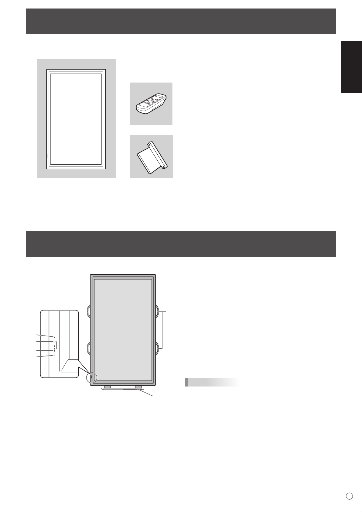
Supplied Accessories
� Liquid Crystal Display: 1
� Remote control unit: 1
� Power cord: 1
� R-6 battery: 2
� CD-ROM (Utility Disk for Windows): 1
� Operation manual: 1
� Stand hole protection cover: 2
INPUT
6
1
2
3
4
5
7
If any component should be missing, please contact your dealer.
* Sharp Corporation holds authorship rights to the Utility Disk programme. Do not reproduce it without permission.
* For environmental protection!
Do not dispose of batteries in household waste. Follow the disposal instructions for your area.
ENGLISH
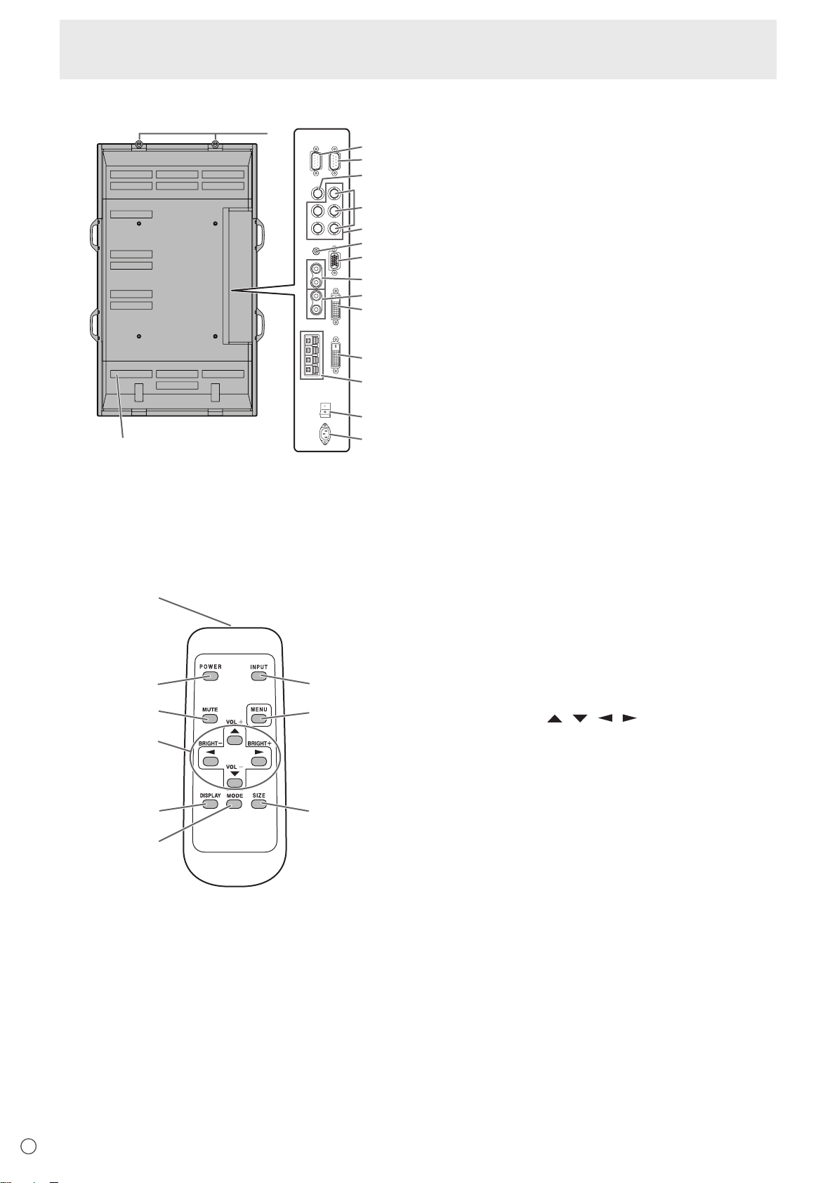
Front view
Part Names
1. LCD panel
2. Remote control sensor (See page 12.)
3. Power LED (See page 14.)
4. Power switch (See page 14.)
5. Input switch (See page 15.)
6. Handles (See page 13.)
7. Temporary Stand
TIPS
• Use a pointed object such as a pen tip to press the
switches at the front of the monitor.
(See page 13.)
7
E
Page 10
Part Names
12
7
5
3
1
8
11
14
16
15
13
10
6
4
2
9
1
2
3
4
5
6
9
8
7
Rear view
1. RS-232C output terminal (D-sub 9 pin) (See page 24.)
2. RS-232C input terminal (D-sub 9 pin) (See page 24.)
3. AV3 input terminal (BNC) (See page 10.)
4. AV2 input terminals (BNC) (See page 10.)
5. PC3 input terminals (BNC) (See page 10.)
6. PC audio input terminal (See page 10.)
7. PC2 input terminal (Mini D-sub 15 pin) (See page 10.)
8. AV audio input terminals (See page 10.)
9. PC/AV audio output terminals (See page 11.)
10
. PC1 input terminal (DVI-D) (See page 10.)
AV1 input terminal
11. PC/AV output terminal (DVI-D) (See page 11.)
12.
External speaker terminals (See page 11.)
13. Main power switch
14. AC input terminal (See page 12.)
15. Vents
16. Hooks
(DVI-D) (See page 10.)
(See page 14.)
Remote control unit
1. Signal transmitter
2. POWER button (See page 14.)
3. MUTE button (See page 15.)
4. VOL +/- buttons (See page 15.)
BRIGHT +/- buttons (See page 15.)
Cursor control ( / / / ) buttons
5. DISPLAY button (See page 15.)
6. MODE button (See page 15.)
7. INPUT button (See page 15.)
8. MENU button (See page 17.)
9. SIZE button (See page 15.)
E
8E8
Page 11
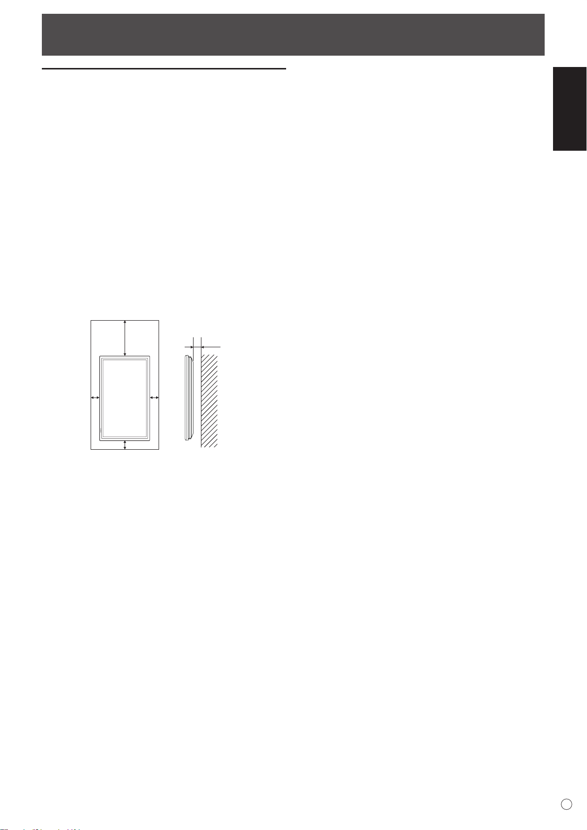
How to Install the Monitor
Unit: cm
5
4.5
30
5 5
Mounting precautions
• Since the monitor is heavy, consult your dealer before
installing, removing or moving the monitor.
• When installing, removing or moving the monitor, ensure
that this is carried out by at least 3 people.
• When moving the monitor, be sure to hold it with the
handles both on the rear and the unit bottom. Do not hold
the LCD panel. This may cause product damage, failure, or
injury.
• Install the monitor with the surface perpendicular to a
level surface. If necessary, limit the tilt between 0 and 20
degrees downward.
• Mounting the monitor on the wall requires special expertise
and the work must be performed by an authorised SHARP
dealer. You should never attempt to perform any of this
work yourself. Our company will bear no responsibility
for accidents or injuries caused by improper mounting or
mishandling.
• This monitor should be used at an ambient temperature
between 0°C and 40°C. Provide enough space around the
monitor to prevent heat from accumulating inside.
ENGLISH
If it is difficult to provide such space because the monitor is
installed inside a housing or for other reasons, take other
measures to keep the ambient temperature between
0°C and 40°C such as installing a fan in the housing.
• This monitor must be installed in a vertical orientation only.
It cannot be installed in a horizontal orientation.
• Do not block any ventilation openings. If the temperature
inside the monitor rises, this could lead to a malfunction.
• After mounting, it is recommended to take some measures
to prevent the monitor from falling down. Secure the
monitor by fastening the hooks at the top of the monitor to a
wall or a pillar with strong cord and brackets (not included).
• Do not place the monitor on a device which generates heat.
• This monitor is fixed to the temporary stand when shipped
from the factory. Please note that this stand is for temporary
use only until the monitor is properly mounted.
• Be sure to use a stand or a wall-mount bracket designed or
designated for mounting the monitor.
• This monitor is designed to be installed on a concrete wall
or pillar. Reinforced work might be necessary for some
materials such as plaster / thin plastic board / wood before
starting installation.
This monitor and bracket must be installed on a wall which
can endure at least 4 times or more the weight of the
monitor. Install by the most suitable method for the material
and the structure.
9
E
Page 12
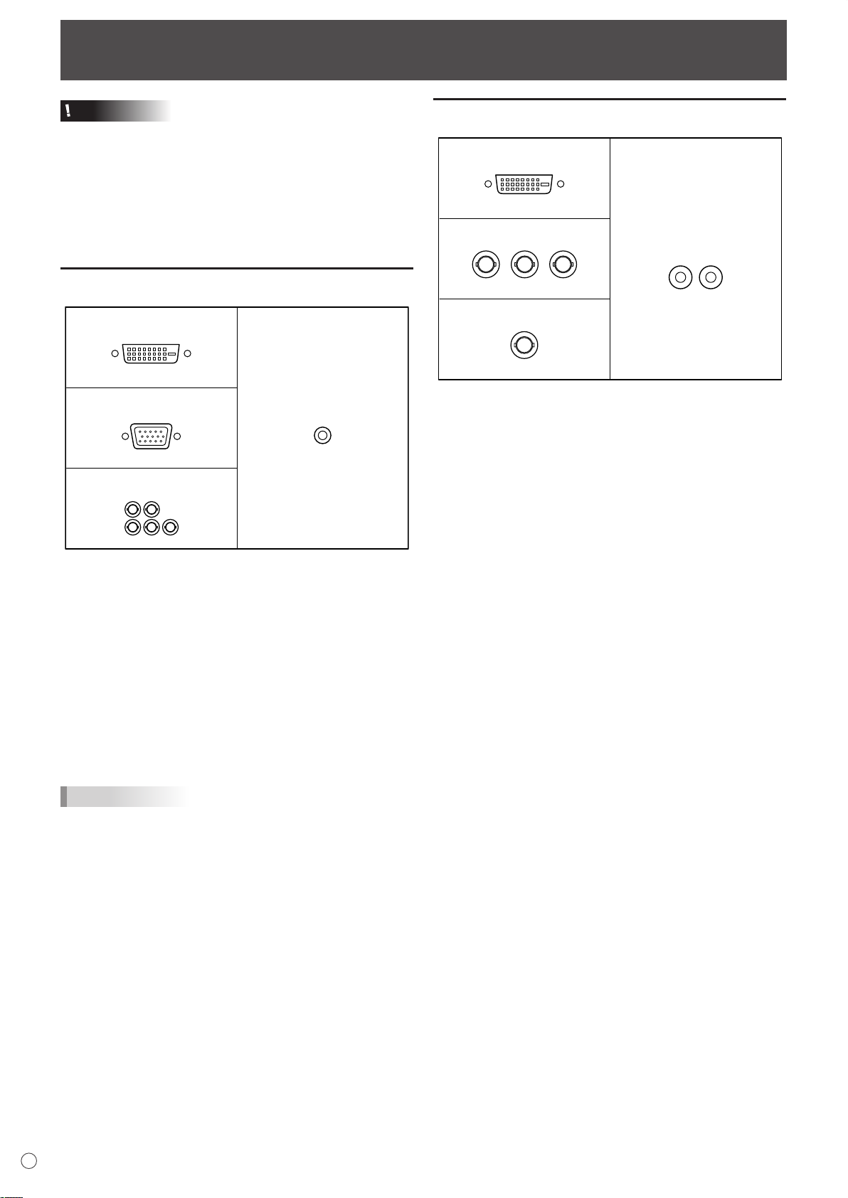
Connecting Peripheral Equipment
PC1 input terminal
PC audio input terminal
PC2 input terminal
PC3 input terminals
HV
R G
B
AV1 input terminal
AV audio input terminals
AV2 input terminals
AV3 input terminal
Cr/Pr Y Cb/Pb
Caution
• Be sure to turn off the main power switch and disconnect
the plug from the power outlet before connecting/
disconnecting cables. Also, read the manual of the
equipment to be connected.
• Be careful not to mix up the input terminal with the output
terminal when connecting cables. Mixing up the input and
output terminals may cause malfunctions and the other
problems.
Connection with a PC
• Use a commercially available signal cable (DVI-D 24
pin) for the PC1 input terminal. Set DVI SELECT on the
OPTION menu to PC (DIGITAL) when using the PC1 input
terminal. (See page 19.)
• Use a commercially available signal cable (Mini D-sub
15 pin) for the PC2 input terminal.
• Use a commercially available signal cable (BNC) for the
PC3 input terminals. Set BNC SELECT on the OPTION
menu to PC (ANALOG) when using the PC3 input
terminals. (See page 19.)
• Use a commercially available audio cable (mini stereo jack)
for the PC audio input terminal. Use an audio cable without
resistance.
TIPS
• Images may not be displayed properly depending on the
computer (graphics board) to be connected.
• A screen with 1920 x 1080 resolution may not be displayed
correctly on PC3 (BNC). In this case, check the settings of
your computer (graphics board) to verify that input signals
conform to specifications of this monitor (Hsync: 66.3 kHz,
Vsync: 60 Hz, and Dot frequency: 148.5 MHz). (See page
34.)
• If there is a check box to disable EDID in display control
panel, check it when using PC3 (BNC).
• Use the automatic screen adjustment when a PC screen is
displayed for the first time using PC2 or PC3, or when the
setting of the PC is changed. (See page 22.)
• The screen is adjusted automatically when SELF ADJUST
in the OPTION menu is set to “ON”. (See page 19.)
Connection with AV equipment
• Use a commercially available signal cable (DVI-D 24 pin)
for the AV1 input terminal. Set DVI SELECT on the OPTION
menu to AV (DIGITAL) when using the AV1 input terminal.
(See page 19.)
• Use a commercially available component cable (BNC) for
the AV2 input terminals. Set BNC SELECT on the OPTION
menu to AV (COMPONENT) when using the AV2 input
terminals. (See page 19.)
• Use a commercially available video cable (BNC) for the
AV3 input terminal.
• Use a commercially available audio cable (RCA) for the AV
audio input terminals.
• The AV1 input terminal is compatible with the video signals
below:
1920 x 1080 p @ 50/59.94/60 Hz
1920 x 1080 i @ 50/59.94/60 Hz
1280 x 720 p @ 50/59.94/60 Hz
720 x 576 p @ 50 Hz
720 x 480 p @ 59.94/60 Hz
640 x 480 p @ 59.94/60 Hz
• The AV2 input terminals are compatible with the video
signals below:
1080i (1125i)/50, 1080i (1125i)/60, 720p (750p)/50,
720p (750p)/60, 576p (625p), 576i (625i), 480p (525p),
480i (525i)
E
10
Page 13
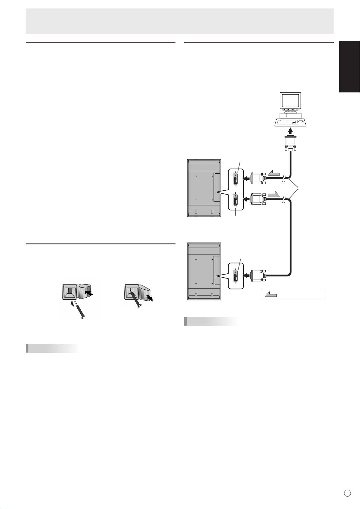
Connecting Peripheral Equipment
(1) (2)
Digital signal
(DVI) cables
(commercially
available)
To
PC
digital RGB
output terminal
shows the signal flow
PC/AV output terminal
PC1/AV1 input terminal
PC1/AV1 input terminal
First monitor
Second monitor
Other terminals
PC/AV audio output terminals
• Audio from the equipment connected to the AV audio input
terminals or PC audio input terminal is output. Connect to
the audio input terminals of the connected equipment using
a commercially available audio cable (RCA).
• The audio output varies depending on the input mode
selection. (See page 15.)
• The volume level can be adjusted using the volume
adjustment. (See page 15.)
• Selecting FIXED of “AUDIO OUTPUT” from the OPTION
menu fixes the volume of sound output from the audio
output terminals. (See page 19.)
• Audio signals output from the PC/AV audio output terminals
cannot be adjusted using the AUDIO menu.
PC/AV output terminals
Video signals from PC1 and AV1 can be output to
HDCP-compatible external device. Use this terminal when
you connect multiple monitors in a daisy chain via DVI cable
(commercially available). (See the description on the right.)
Images cannot be output to device that is not
HDCP-compatible.
RS-232C input/output terminals
You can control the monitor from a PC by connecting a
commercially available RS-232 straight cable between this
terminal and the PC. (See page 24.)
Connecting multiple monitors
You can connect multiple monitors (up to 5 monitors) in a
daisy chain by using the PC1/AV1 input terminals and PC/AV
output terminals of this monitor.
Connection example
ENGLISH
Connecting external speakers
Be sure to use external speakers with an impedance of 6 Ω
and a rated input of at least 7 W.
1. While pushing the tab, insert the tip of the cable.
2. Release the tab.
TIPS
• Be sure to connect the + and - terminals and the left and
right speakers properly.
• Avoid short circuiting the + and - terminals.
TIPS
• The length of the signal cables or surrounding environment
may affect the image quality.
• The screen may not display properly when using terminals
other than PC1/AV1 for the input mode. In this case, turn
off the power to all the monitors connected in a daisy chain
and then turn the power on again.
11
E
Page 14
10°
5
m
5 m
5 m
Remote control
sensor
10°
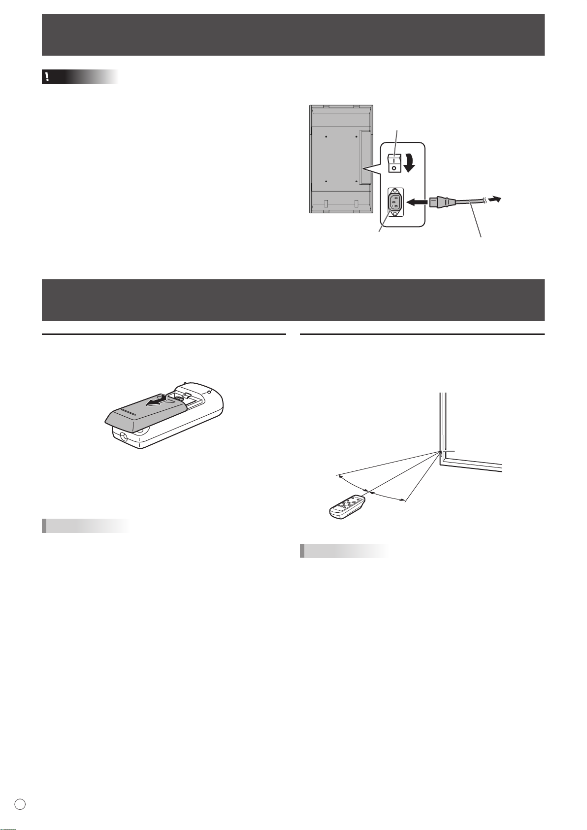
Connecting the Power Cord
2
Power cord (Supplied)
For power
outlet
3
1
Main power switch
AC input terminal
Caution
• Do not use a power cord other than the one supplied with the monitor.
1. Turn off the main power switch.
2. Plug the power cord (supplied) into the AC input terminal.
3. Plug the power cord (supplied) into the AC power outlet.
Preparing the Remote Control Unit
Installing the batteries
1. Press the cover gently and slide it in the direction of the
arrow.
2. See the instructions in the compartment and put in the
supplied batteries (2 R-6 batteries) with their plus (+) and
minus (-) sides oriented correctly.
3. Close the cover.
TIPS
• The supplied batteries (2 R-6 batteries) may become
exhausted faster depending on the storage condition. It is
recommended that you replace them with new batteries
(commercially available) earlier than specified.
• If you will not use the remote control for a long time,
remove the batteries.
• Use manganese or alkaline batteries only.
Remote control operation range
The operation range of the remote control unit is approx. 5 m
at an angle of approx 10° from the centre to the top/bottom/
right/left of the remote control sensor.
TIPS
• Do not expose the remote control unit to shock by dropping
or stepping on it. This could lead to a malfunction.
• Do not expose the remote control unit to liquids, and do not
place it in an area with high humidity.
• The remote control unit may not work properly if the remote
control sensor is under direct sunlight or strong lighting.
• Objects between the remote control unit and the remote
control sensor may prevent proper operation.
• Replace the batteries when they run low as this may
shorten the remote control’s operation range.
• If a fluorescent light is illuminated near the remote control
unit, it may interfere with proper operation.
• Do not use it with the remote control of other equipment
such as air conditioner, stereo components, etc.
E
12
Page 15
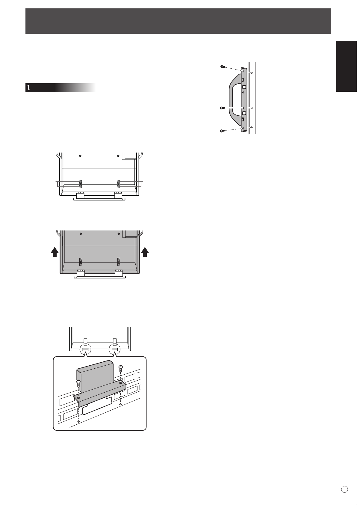
Removing the Temporary Stand and the Handles
Removing the Temporary Stand
Prepare wall-hanging brackets or a stand to mount the monitor
unit. Read the manual for the brackets or stand for the proper
mounting procedure. (The screw holes for mounting brackets
(M10 x 4 holes) are provided on the rear of the monitor.)
Caution
• The monitor is heavy. Make sure to handle the monitor with
at least 3 people.
• This monitor is fixed to the temporary stand when shipped
from the factory. Please note that this stand is for temporary
use only until the monitor is properly mounted.
1. Hold the monitor with the handles to prevent it from falling
down, and remove the stand fixing screws (4).
ScrewsScrews
2. Lift the monitor by holding it with the handles and the
underside of the unit.
Removing the Handles
The handles are detachable.
After you removed the handles, be sure to replace the
removed screws in the original holes.
ENGLISH
3. When the installation is complete, attach the included stand
hole protection covers, using the supplied screws.
(1) Remove the screws from the monitor unit.
(2) Secure the stand hole protection covers with the screws
removed in step (1).
• The temporary stand is specifically designed for this
monitor. Do not use for other devices.
13
E
Page 16
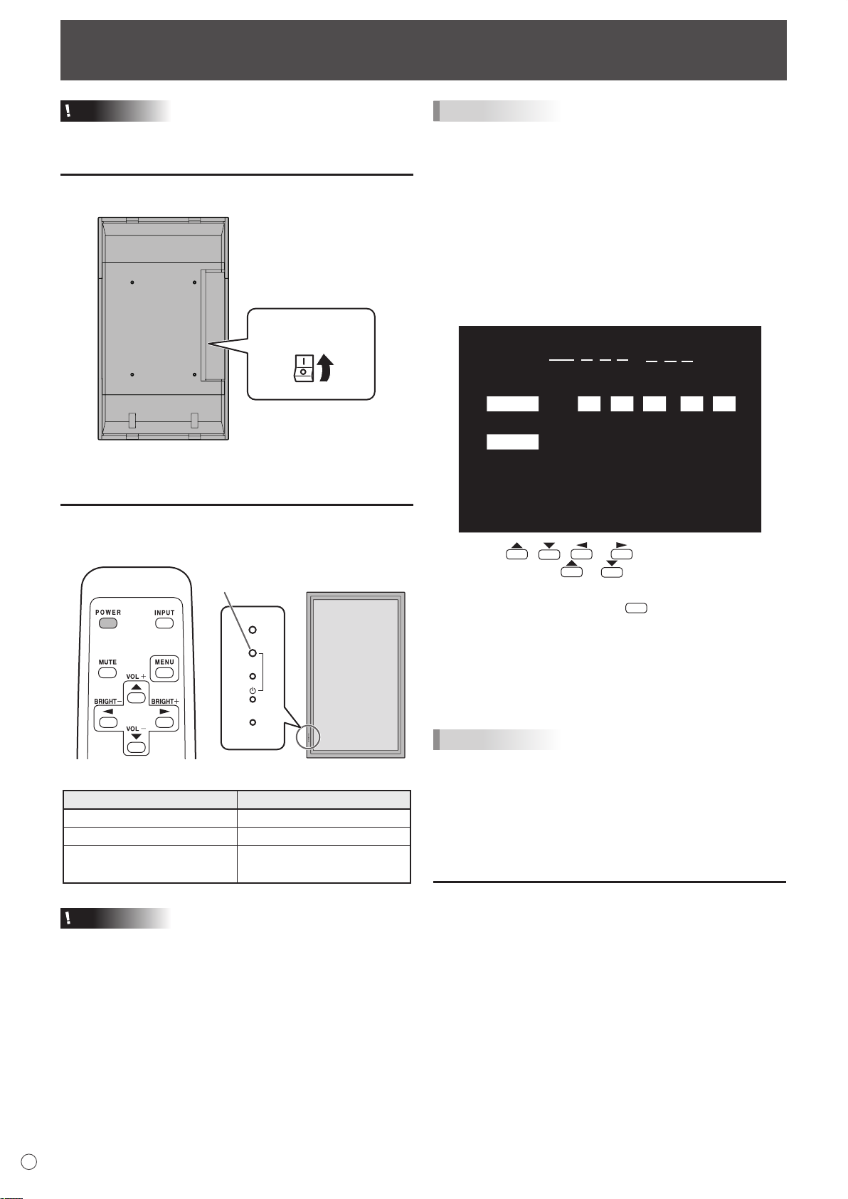
Turning Power On/Off
Main power switch
IN
PU
T
Power LED
DATE/TIME SETTING
SET
CANCEL
07
/ /
OK···[MENU]
20
01/01/00 00
:
: :
MENU
Caution
• Turn on the monitor first before turning on the PC or
playback device.
Turning on the main power
When the main power switch is off, the monitor cannot be
turned on using the POWER button on the remote control unit.
Turning power on/off
TIPS
• If the monitor is in the input signal standby mode and you
press the POWER button on the remote control unit, the
monitor enters standby mode.
• You can turn on/off the monitor by pressing the power
switch of the monitor.
• Setting the SCHEDULE flashes the power LED alternately
in red and orange in standby mode.
Date/time setting
• If the time has yet to be set when the monitor is first turned
on, the date/time setting screen appears. Set the date and
time.
Press the POWER button to turn the power ON/OFF.
Status of a power LED Status of the monitor
Green lighting Power “On”
Orange lighting Power “Off” (Standby mode)
Green flashing
Caution
Input signal standby mode
(input using a PC)
• When switching the main power switch or the POWER
button off and back on, always wait for at least 5 seconds.
A short interval may result in a malfunction.
1. Press , , or to select the date and
time, and press or to change the numerical
values.
2. Select SET and then press
.
• Be sure to set the date and time.
• The date/time setting screen will close automatically if no
operation is performed for about 15 seconds. The date
and time can be set using DATE/TIME SETTING from
the OPTION menu when the date/time setting screen
disappears.
TIPS
• Set the date in “Year/Month/Day” order.
• Set the time on a 24-hour basis.
• The clock stops after the power-off status continues for
approximately 1 week.* The date/time setting screen
appears at power-on. Be sure to set the date and time.
(* This is a guide. The power-off status that stops the clock
depends on the status of the monitor.)
Disabling power on/off operations
Power on/power off operations can be disabled in order to
protect the monitor from an accidental power off. Set the
ADJUSTMENT LOCK in FUNCTION menu to “2”. (See page
23.)
E
14
Page 17
Basic Operation
1
2
3
4
5
6
7
8
V O L U M E 15
B R I G H T 15
INPUT MODE
SIZE
COLOR MOD
E
BRIGHT
VOLUM
E
ID No.
MODE
L
S/N
PC2 ANALOG
WIDE
ST
D
15
15
0
PN-G655RE
:
:
:
:
:
:
:
:
1 0 2 4 x 7 6 8
INFORMATION XXXX/XX/XX XXX XX:XX:X
X
V: 60 Hz H: 48.4 kH
z
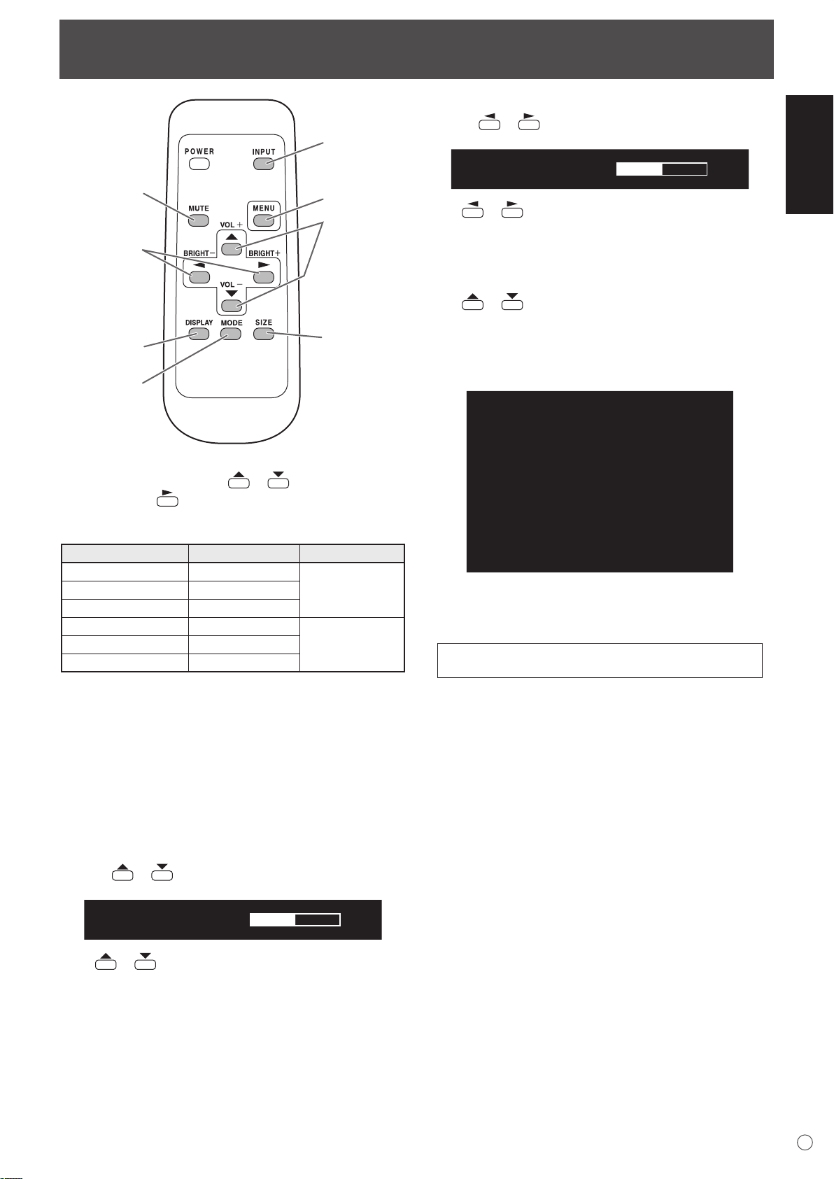
1. INPUT (Input mode selection)
The menu is displayed. Press or to select the input
mode, and press to enter.
* You can select the input terminal by pressing the input
switch of the monitor.
Input mode Video Audio
PC1 DIGITAL
PC2 ANALOG
PC3 ANALOG
AV1 DIGITAL
AV2 COMPONENT
AV3 VIDEO AV3 input terminal
*1
*2
*1
PC1 input terminal
PC2 input terminal
PC3 input terminals
AV1 input terminal
*2
AV2 input terminals
PC audio input
terminal
AV audio input
terminals
5. BRIGHT +/- (Backlight adjustment)
Pressing or displays the BRIGHT menu when the
menu screen is not displayed.
Press or to adjust the brightness.
* If you do not press any buttons for about 4 seconds, the
BRIGHT menu automatically disappears.
6. SIZE (Screen size selection)
The menu is displayed.
Press or to select the screen size. (See page 16.)
7. DISPLAY
Displays monitor information. The display disappears when
this button is pressed again or disappears automatically after
approximately 15 seconds.
8. MODE (Colour mode selection)
Each time you press this button, the colour mode changes in
the following order:
STD (Standard) → VIVID → sRGB → STD...
ENGLISH
*1 Select the terminal for DVI SELECT. (See page 19.)
*2 Select the terminal for BNC SELECT. (See page 19.)
2. MUTE
Turns off the volume temporarily.
Press the MUTE button again to turn the sound back to the
previous level.
3. MENU
Displays and turns off the menu screen (see page 17).
4. VOL +/- (Volume adjustment)
Pressing or displays the VOLUME menu when the
menu screen is not displayed.
Press or to adjust the volume of the sound.
* If you do not press any buttons for about 4 seconds, the
VOLUME menu automatically disappears.
• sRGB applies to PC input only.
sRGB is international standard of colour representation
specified by IEC (International Electrotechnical
Commission). Colour conversion is made in taking account
of liquid crystal’s characteristics and represents colour tone
close to its original image.
E
15
Page 18
Basic Operation
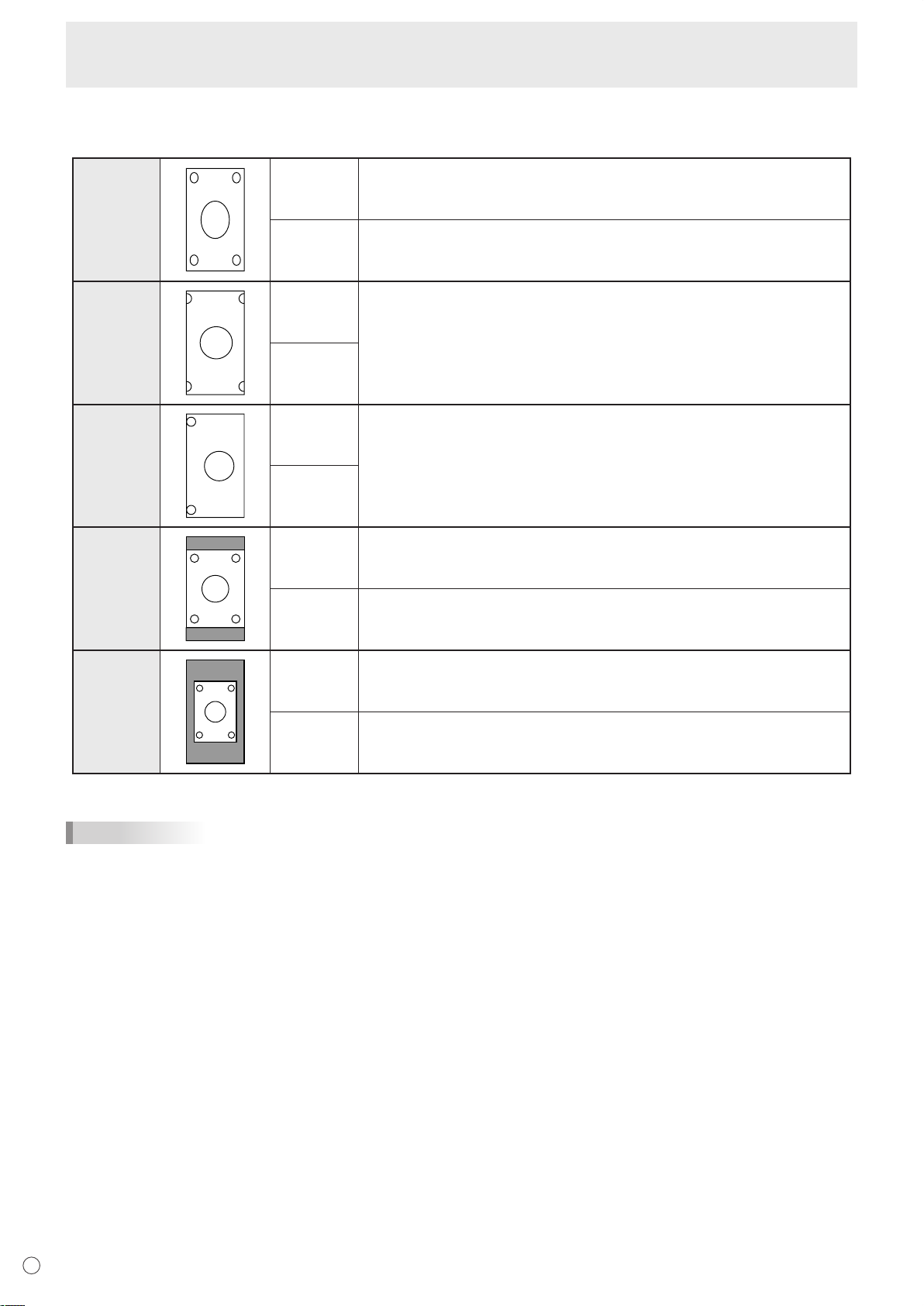
Switching the screen size
Even when the screen size is changed, the display may remain the same depending on the input signal.
WIDE PC input Displays image so it fills the entire screen.
AV input An image with a 4:3 aspect ratio is stretched to fill the entire screen.
ZOOM 1 PC input An image with a 4:3 aspect ratio is enlarged to fill the entire screen without
changing the aspect ratio. The edges of the image may be cut off.
AV input
ZOOM 2 PC input Use this size if ZOOM 1 cuts off the subtitles.
AV input
NORMAL PC input Displays image so it fills the screen without changing the aspect ratio of the
input signals.
AV input
DotbyDot PC input Displays the dots of the signals input from the connected PC as the
AV input
*: With a monitor with a screen resolution of 1600 x 1200, selecting DotbyDot displays the NORMAL screen.
TIPS
• Using this monitor’s screen-size switching or dual-screen display functions to compress or expand the screen for commercial
or public viewing in establishments like cafes or hotels may infringe on the rights of the creators, as protected by Copyright
Law, so please be careful.
• When “Enlarge” is set, the screen size is fixed to “WIDE” mode.
• When dual-screen display is selected, the screen size cannot be changed.
• The appearance of the original video may change if you select a screen size with a different aspect ratio than the original
image (e.g. TV broadcast or video input from external equipment).
• When an ordinary non-wide image (4:3) is viewed with the whole screen using the screen-size switching function of this
monitor, the edge of the image may be lost or appear distorted. If you wish to respect the creator’s intentions, set the screen
size to “NORMAL”.
• When playing commercial software, parts of the image (like subtitles) may be cropped. In this case select the optimal screen
size using the screen-size switching function of this monitor. With some software, there may be noise or distortion at the
edges of the screen. This is due to the characteristics of the software, and is not a malfunction.
• Depending on the original image size, black bands may remain at the edges of the screen.
Displays the entire image of the aspect ratio of 4:3 without changing the aspect
ratio.
corresponding dots on the screen. *
Displays the dots of the input signals as the corresponding dots on the screen.
E
16
Page 19
Menu Items
MENU
1 0 2 4 x 7 6 8
V: 60 Hz H: 48.4 kHz
AUTO
CLOC
K
PHASE
H-POS
V-POS
RESE
T
SCREEN
PICTURE
AUDIO
SETUP
OPTION
ENLARGE
PIP/PbyP
127
31
31
150
SCREEN PC2 ANALOG1/1
END···[MENU]
AUTO
CONTRAST
BLACK LEVEL
SHARPNESS
30
96
12
PC2 ANALOG1/2
PICTURE
SCREEN
PICTURE
AUDIO
SETUP
OPTION
ENLARGE
PIP/PbyP
OK···[MENU]
1 0 2 4 x 7 6 8
V: 60 Hz H: 48.4 kHz
AUTO
CONTRAST
BLACK LEVEL
SHARPNESS
40
96
12
PC2 ANALOG1/2
PICTURE
SCREEN
PICTURE
AUDIO
SETUP
OPTION
ENLARGE
PIP/PbyP
OK···[MENU]
1 0 2 4 x 7 6 8
V: 60 Hz H: 48.4 kHz
MENU
MENU
AUTO
CONTRAST
BLACK LEVEL
SHARPNESS
30
96
12
PC2 ANALOG1/2
PICTURE
SCREEN
PICTURE
AUDIO
SETUP
OPTION
ENLARGE
PIP/PbyP
OK···[MENU]
1 0 2 4 x 7 6 8
V: 60 Hz H: 48.4 kHz
4
1 3 2
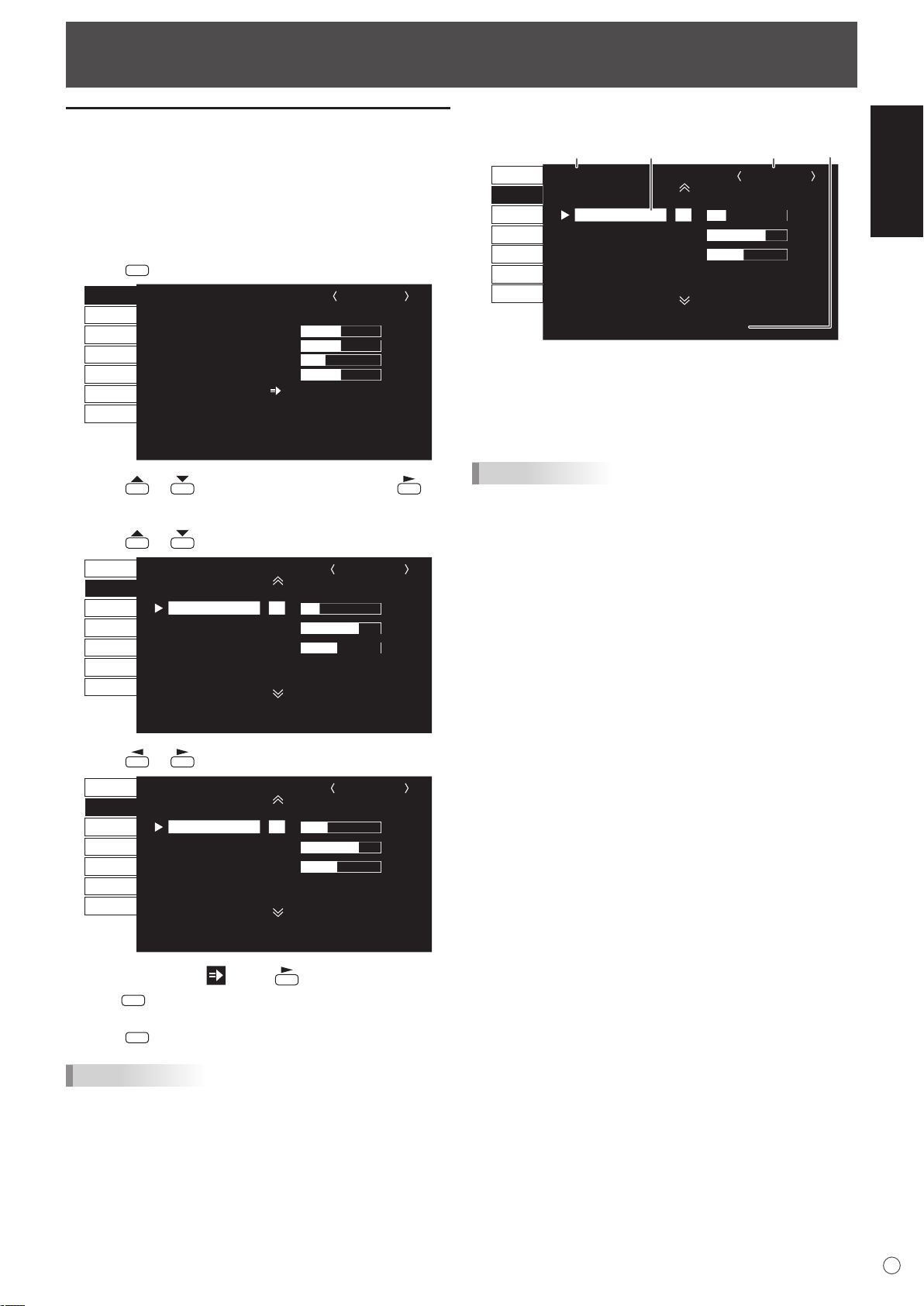
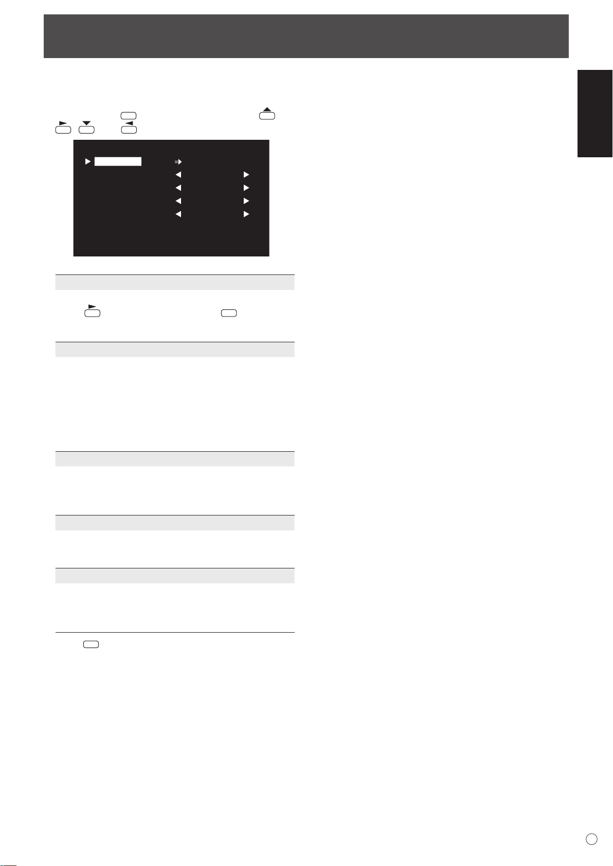
Displaying the menu screen
Video and audio adjustment and settings of various functions
are enabled. This section describes how to use the menu
items. See pages 18 to 20 for details of each menu items.
Example of operation
(Adjusting CONTRAST in the PICTURE menu)
1. Press
2. Press or to select PICTURE, and press .
PICTURE menu is displayed.
3. Press
to display the menu screen.
to select CONTRAST.
or
Menu screen display
1 Name of the menu
2 Input mode
3 An item being selected (highlighted)
4 Screen resolution of input signal, and other data.
TIPS
• Items that cannot be selected appear in grey.
(e.g. Function not supported by the current input signal)
ENGLISH
4. Press or to adjust the setting.
For items that have , press , make settings and then
press
5. Press
TIPS
• The menu will differ depending on the input mode.
• The menu screen will close automatically if no operation is
performed for about 15 seconds. (DATE/TIME SETTING
and SCHEDULE screens will close in about 4 minutes.)
.
twice to close the menu screen.
17
E
Page 20
MENU
MENU
MENU
MENU
Menu Items
Menu item details
The menu will differ depending on the input mode.
SCREEN (PC2/PC3)
AUTO
The CLOCK, PHASE, H-POS, and V-POS are automatically
adjusted.
Pressing
Use this automatic adjustment when you use the PC2 input
terminal or PC3 input terminals to display a PC screen for
the first time or when you change the setting of the PC. (See
page 22.)
CLOCK
Adjusts frequency for sampling clock for applicable video.
Adjust when there is flickering in the form of horizontal
stripes.
When using the adjustment pattern (see page 22), make
adjustments so that no horizontal stripe noise appears in it.
PHASE
Adjusts sampling clock phase for applicable video.
Useful when small characters appear with low contrast and/
or there are flickers at corners.
When using the adjustment pattern (see page 22), make
adjustments so that no vertical stripe noise appears in it.
* Adjustments to PHASE should be made only after CLOCK
H-POS
Adjust the horizontal position of the image.
V-POS
Adjust the vertical position of the image.
RESET
Resets the values of the SCREEN menu items to the factory
preset values.
Select “ON” and then press
performs adjustment.
has been correctly set.
.
COLOR MODE
Changes the colour mode on the screen. The colour mode
on the screen can also be changed using a remote control
unit. (See page 15.)
* sRGB is PC input only. See page 15 for details.
WHITE BALANCE
THRU .............. Displays the input signal level as is.
(for PC1 only)
PRESET ......... Selects the colour temperature using
PRESET.
USER .............. Used for adjusting R-CONTRAST,
G-CONTRAST, and B-CONTRAST
respectively.
PRESET
Selects the colour temperature when the WHITE BALANCE
is set to PRESET.
R-CONTRAST
Adjusts red component when the WHITE BALANCE is set to
USER.
G-CONTRAST
Adjusts green component when the WHITE BALANCE is set
to USER.
B-CONTRAST
Adjusts blue component when the WHITE BALANCE is set
to USER.
COPY TO USER
Copies the value set for PRESET to the USER setting.
Select “ON” and then press
GAMMA
Select a gamma value.
RESET
Resets the values of the PICTURE menu items to the factory
preset values.
Select “ON” and then press
.
.
PICTURE
AUTO (PC2/PC3)
The CONTRAST and BLACK LEVEL are automatically
adjusted.
Pressing
CONTRAST
Adjusts the brightness of the image.
BLACK LEVEL
Adjusts the entire brightness of the video signals.
TINT (AV input)
Adjusts the hue. Selecting + changes the colour towards
green, and selecting - changes it towards magenta.
COLORS (AV input)
Adjusts the colour intensity.
SHARPNESS
Adjusts the sharpness of the image.
ADVANCED (AV input)
You can adjust more specifically. (See page 22.)
E
18
performs adjustment.
AUDIO
TREBLE
Adjusts the volume of treble-level sound.
BASS
Adjusts the volume of bass-level sound.
BALANCE
Adjusts the balance of the audio sound between right and left.
RESET
Resets the values of the AUDIO menu items to the factory preset values.
Select “ON” and then press
.
Page 21

STANDARD MIRROR ROTATEUPSIDE DOWN
ABC
ABC
ABC
ABC
Menu Items
SETUP
OSD H-POSITION
Adjusts the horizontal display position of menu screen.
OSD V-POSITION
Adjusts the vertical display position of menu screen.
LANGUAGE
Sets the display language for the menu screen.
ID No. SET
Assigns ID numbers to monitors connected in a daisy chain
(see page 25), using RS-232 cables.
The numbers 1 to 255 are available for ID numbers.
If “0” is set, the system regards this as the state where no ID
number is set.
PICTURE FLIP
A picture flips to appear.
POWER ON DELAY
You can delay the screen display after the monitor is turned
on. The period can be set up to 60 seconds in units of one
second. When this function is activated, the power LED
flashes (at approx. 1 second interval) in orange. This function
is disabled when 0 is specified.
OPTION
DATE/TIME SETTING
Set the date and time. Press or to select the date
and time, and press or to change the numerical
values.
Set the date in “Year/Month/Day” order.
Set the time on a 24-hour basis.
SCHEDULE (See page 21.)
You can set the time to switch the monitor on and off.
DVI SELECT
Selects equipment that is to be connected to the PC1/AV1
input terminal.
BNC SELECT
Selects equipment that is to be connected to the PC3/AV2
input terminals.
QUICK SHOOT
Reduces the visual lag inherent in fast-motion scenes.
COLOR SYSTEM
Select the colour system of the AV equipment which is
connected to AV3 input terminal. (AUTO / PAL / PAL-60 /
SECAM / NTSC3.58 / NTSC4.43)
When AUTO is selected, the colour system is automatically
set according to the input signal.
AUDIO OUTPUT
Sets the volume of sound output from the PC/AV audio
output terminals.
VARIABLE .......... You can adjust the volume using VOLUME.
FIXED ................. Fixes the sounds.
480LINES (PC2/PC3)
If a computer connected to the PC2/PC3 input terminal has
a resolution of 640 x 480 or 848 x 480, make a selection
according to the resolution.
768LINES (PC2/PC3)
If a computer connected to the PC2/PC3 input terminal has a
resolution of 1024 x 768, 1280 x 768 or 1360 x 768, make a
selection according to the resolution.
SELF ADJUST
On a PC2/PC3 screen with a resolution of 800 x 600 or
higher, specify whether to perform screen adjustment
automatically or not. When ON is selected, the screen is
automatically adjusted when the timing of input signals
varies. “ADJUSTING” appears on the screen during the
adjustment.
POWER MANAGEMENT
POWER MANAGEMENT determines whether or not to
switch modes from no signal to the input signal standby
mode when the PC screen is displayed.
ENGLISH
19
E
Page 22
Menu Items
Main screen
Sub
screen
Main
screen
Sub
screen
Main screen
Sub
screen
ENLARGE (PC input)
ENLARGE MODE
Sets the number of screen splits used for the enlargement.
(See page 21.)
ENLARGE POS
Specify the split screen to be displayed when the
enlargement function is used. (See page 21.)
BEZEL H / BEZEL V
Sets the frame width of the display when the enlargement
function is used.
H-POS
Adjust the horizontal position of the enlarged screen.
V-POS
Adjust the vertical position of the enlarged screen.
PIP/PbyP
PIP MODES
Sets the display method.
OFF .........Displays one screen.
PIP ...........Displays a sub screen inside a main screen.
PbyP ........Displays a main screen and a sub screen in a line.
PbyP2 ......Displays a main screen which measures 1280
pixels in the longest direction and a sub screen in
a line.
PIP SIZE
Sets the size of the sub screen in PIP mode.
PIP H-POS
Adjusts the horizontal position of the sub screen in PIP
mode.
PIP V-POS
Adjusts the vertical position of the sub screen in PIP mode.
PIP BLEND
In PIP mode, use this menu item to display the sub screen
transparently.
PIP SOURCE
Selects the input signal of the sub screen in PIP, PbyP, or
PbyP2 mode.
SOUND CHANGE
Sets the sound which is output in PIP, PbyP, or PbyP2 mode.
If the main screen is displayed as a full screen by the AUTO
OFF function, the sound for the main screen is output even
when the sound for the sub screen is specified.
MAIN POS
Sets the position of the main screen in PbyP or PbyP2 mode.
PbyP2 POS
Sets the position of the sub screen in PbyP2 mode.
AUTO OFF
Sets the display method when no signals for the sub screen
are input in PIP, PbyP, or PbyP2 mode.
MANUAL ....... Displays a main screen and a black sub
screen.
AUTO ............
Displays the main screen as a full screen.
TIPS
• When WHITE BALANCE is set to THRU, BLACK LEVEL,
CONTRAST and GAMMA cannot be set.
• If COLOR MODE is set to sRGB or VIVID, the following
items cannot be set.
WHITE BALANCE, PRESET, R-/G-/B-CONTRAST, COPY
TO USER, and GAMMA
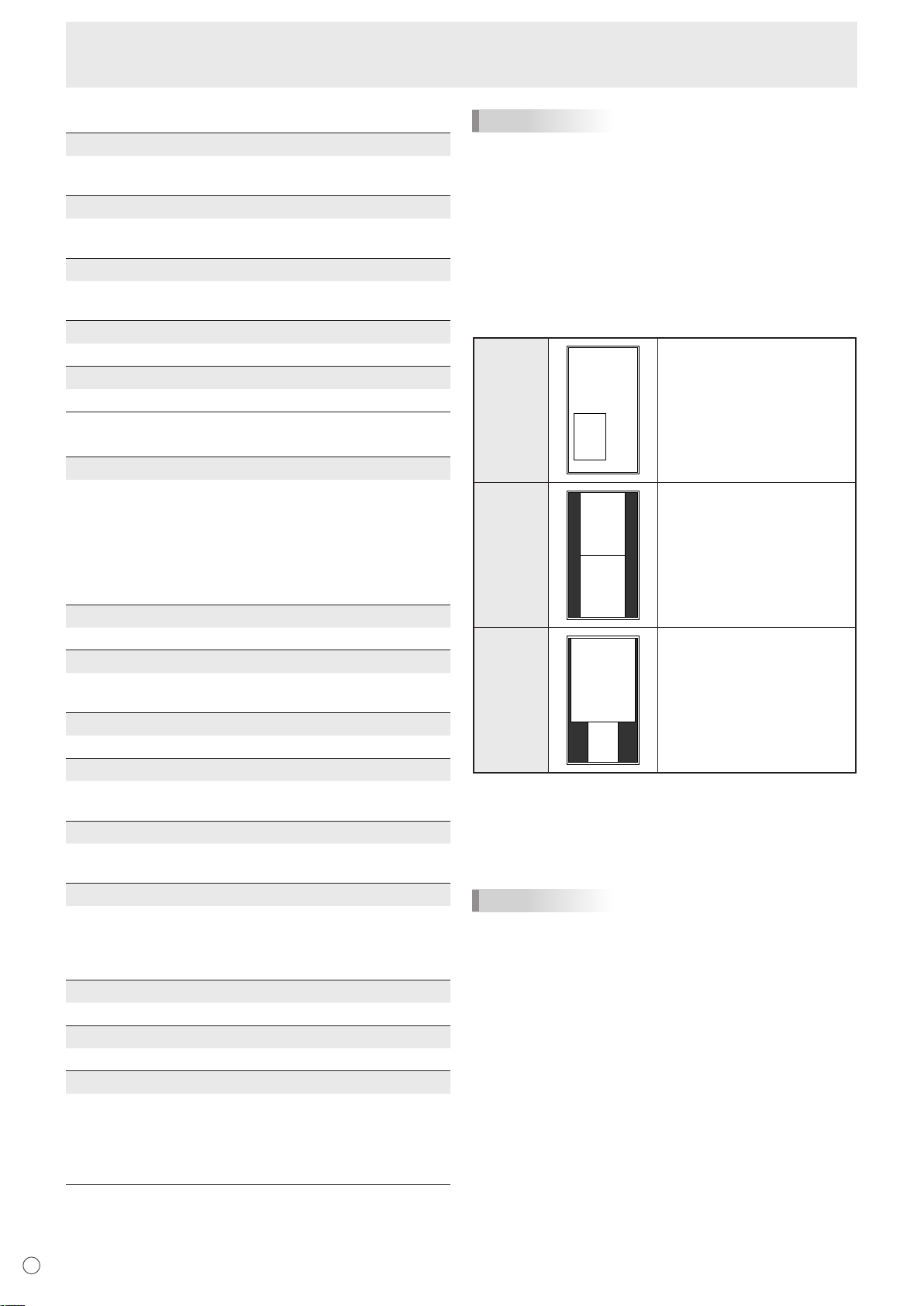
Dual screen display
You can display the screens of the PC input signal and AV
input signal simultaneously.
Set this function with “PIP MODES” in the PIP/PbyP menu.
PIP
PbyP
PbyP2
* The currently selected input signal is displayed on the main
screen.
* You cannot simultaneously display the screens of signals
of the same type, such as two types of PC input signals or
two types of AV input signals.
TIPS
• You might infringe on a copyright of the author which is
protected by copyright law when you display the images of
the computer screen and television/VCR simultaneously for
profit-making or to show the image to the public.
• The screen size for dual-screen display is the same as the
screen size for single-screen display. The DotbyDot screen
is displayed in NORMAL size except when it is set as the
PIP main screen.
• When dual-screen display is selected, the screen cannot
be enlarged.
• When dual-screen display is selected, the following
adjustments of ADVANCED are invalid and adjusting is
disabled.
3D-NR, MPEG-NR and 3D-Y/C
A sub screen is displayed
inside a main screen.
A main screen and a sub
screen are displayed in a line.
Displays a main screen which
measures 1280 pixels in the
longest direction and a sub
screen in a line.
E
20
Page 23
Menu Items
1
3
0
2
0
1
2
4
5
6
8
9
10
3
7
11
12
13
14
15
0
1
2
5
6
7
10
11
12
3
8
13
15
16
17
18
20
21
22
23
4
914
19
24
0
1
2
3
4
5
6
7
8
Original
image
4 monitors 9 monitors
25 monitors16 monitors
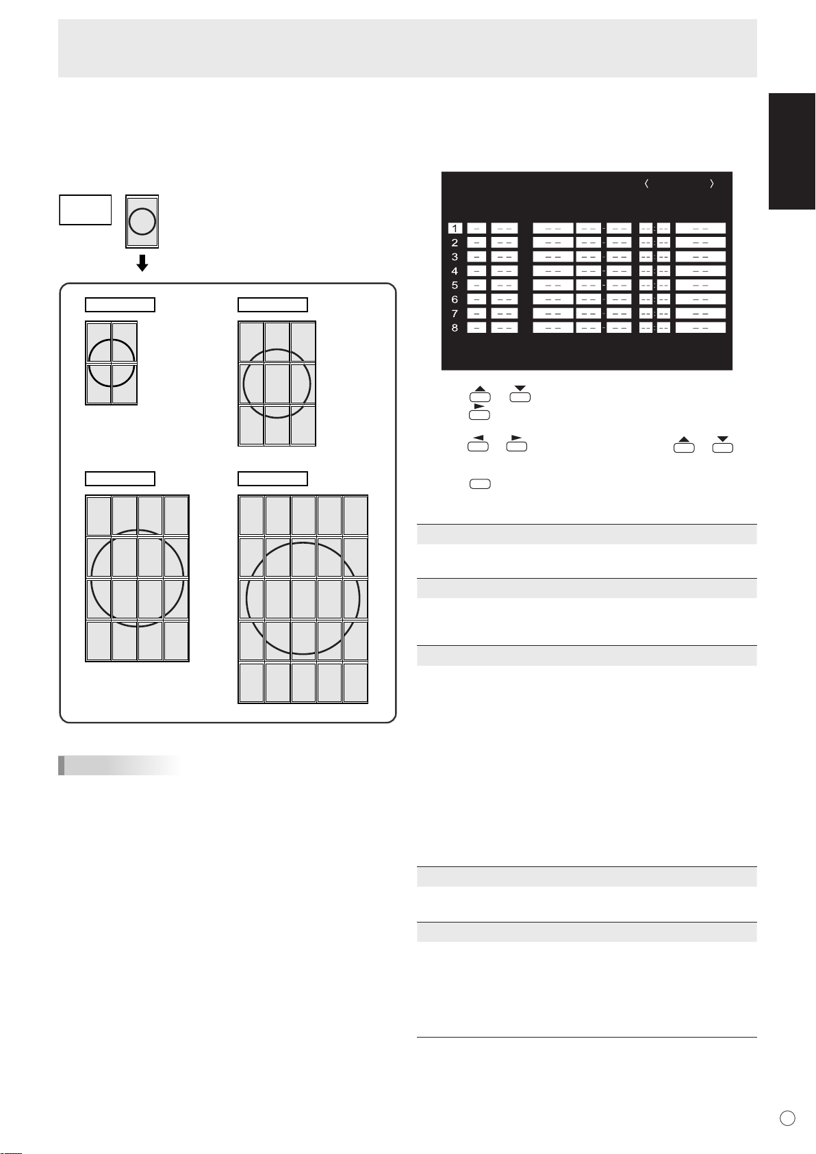
SCHEDULE
No. POWER DAY OF THE WEEK TIME INPUT
XXXX/XX/XX XXX XX:XX:XX
PC2 ANALOG
(2)
OK
…
[MENU]
1 0 2 4 x 7 6 8
V: 60 Hz H: 48.4 kHz
(1)
(3) (4) (5)
MENU
Enlarge
You can align 4, 9, 16, or 25 monitors and integrate them into
a single large screen to display.
Enlarged views of separated images are displayed in each
monitor.
SCHEDULE
You can set the time to switch the monitor on and off.
Set this function with “SCHEDULE” in the OPTION menu. (See
page 19.)
1. Press or to select the SCHEDULE number, and
press .
2. Set the SCHEDULE. (See the description below.)
Press or to select items, and press or to
change the setting.
3. Press
.
SCHEDULE becomes effective.
ENGLISH
TIPS
• AV input signals cannot be used for the Enlarge function.
• To integrate 9 or more monitors using PC1 signals, a
splitter for the video signal (commercially available) is
required.
• When connected in PC2/PC3, a splitter for the video signal
(commercially available) is required.
(1)
●: SCHEDULE effective
-
: SCHEDULE not effective
(2) POWER
ON : Switches the monitor on at the specified time.
OFF : Switches the monitor off at the specified time and puts
the monitor in standby mode.
(3) DAY OF THE WEEK
Specifies the day of the week to execute the SCHEDULE.
ONLY ONCE:
Executes the SCHEDULE once on the specified day.
Specify the day of the week to execute the SCHEDULE.
EVERY WEEK:
Executes the SCHEDULE on the specified day of the week
every week. Specify the day of the week to execute the
SCHEDULE.
Periodic setting such as “Monday through Friday” is also
possible.
EVERY DAY:
Executes the SCHEDULE every day regardless of the day
of the week.
(4) TIME
Specifies the time to execute the SCHEDULE.
Set the time on a 24-hour basis.
(5) INPUT
Specifies the input mode at power-on. When not specifying,
the screen at the previous power-off appears.
Input modes displayed on “PC1/AV1” depend on DVI
SELECT settings.
Input modes displayed on “PC3/AV2” depend on BNC
SELECT settings.
21
E
Page 24
MENU
MENU
Menu Items
Caution
• Do not switch off the main power after setting the
SCHEDULE.
• Specify the correct date and time. (See pages 14 and 19.)
SCHEDULE does not function unless the date and time are
specified.
• Check regularly that the set date and time are correct.
TIPS
• Up to 8 SCHEDULE items can be registered.
• Setting the SCHEDULE flashes the power LED alternately
in red and orange in standby mode.
• A SCHEDULE that has a large number has precedence
over that of a small number when schedules overlap.
ADVANCED items (AV input) (See page 18.)
FLESH TONE
Adjust the hue control.
3D-NR
Reduce the noise of playback images on video.
Setting a higher level reduces more noise. However, it may
cause blurring on an image.
MPEG-NR
Reduce block noise caused by digital compression.
3D-Y/C (AV3)
Specify whether to perform 3-dimension Y/C separation.
If dot interference or cross-colour is occurring in fast-motion
scenes, selecting “OFF” may improve the image quality.
Adjustments for PC screen display
Automatic adjustment
When you use the PC2 input terminal or PC3 input terminals
to display a PC screen for the first time, or when you change
the setting of the PC, use the automatic screen adjustment.
1. Switch the input to PC2 or to PC3 and display the
adjustment pattern. (See the description below.)
2. Press
menu.
3. Press
4. Press
The automatic adjustment is complete in several seconds.
5. Press
TIPS
• If the screen cannot be adjusted properly with one
automatic adjustment, repeat the automatic adjustment two
or three times. Try manual adjustment if necessary.
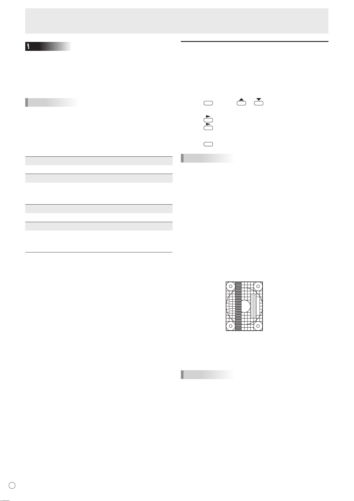
Screen display for adjustment
Before making adjustments in the SCREEN menu or
PICTURE menu, display an image to brighten the entire
screen. If you are using a Windows PC, use the adjustment
pattern on the supplied CD-ROM.
Opening the adjustment pattern
1. Load the supplied CD-ROM into the computer’s CDROM drive.
2. Open the CD-ROM in [My Computer].
3. Double-click [Adj_uty.exe].
The adjustment pattern will appear.
Adjust the screen automatically or manually.
and use or to display the SCREEN
and select “AUTO”.
.
twice to close the menu screen.
4. When adjustment is finished, press the [Esc] on
the computer’s keyboard to quit the adjustment
programme.
5. Eject the CD-ROM from the CD-ROM drive.
TIPS
• If the display mode on the computer you are using is
65,000 colours, the colour levels in the colour pattern may
appear differently or greyscale may appear to be coloured.
(This is due to the specifications of the input signal and is
not a malfunction.)
E
22
Page 25
Initialisation (Reset)/Functional Restriction Setting
SIZE
OFF
ON
ON
UNLOCKE
D
FUNCTION
1/1
ALL RESET
ADJUSTMENT LOCK
OSD DISPLA
Y
LED
RS-232
C
END···[MENU]
MENU
MENU
You can return the settings to their factory-preset values and
restrict operations.
1. After pressing
for about 5 seconds, press ,
, , and in that order.
2. Select and set the items.
ALL RESET
Resets the settings to the factory default settings.
Press , select “ON” and then press
.
After initialisation, turn the main power switch off and
then back on.
ADJUSTMENT LOCK
You can disable operations on the monitor and the
remote control unit that use buttons.
OFF ...Enables operation.
1 ........Disables all operations other than turning power
on/off and FUNCTION.
2 ........Only the FUNCTION operation is enabled.
Disables all operations other than FUNCTION (not
even power on/off).
OSD DISPLAY
Hides/shows menus.
The FUNCTION screen cannot be hidden.
ON ...........Displays the menus.
OFF .........Hides the menus.
LED
Specifies whether to light power LEDs.
ON ...........Lights power LEDs.
OFF .........Does not light power LEDs.
RS-232C
Specifies whether to allow control via RS-232C (see
page 24).
LOCKED .............Disables control via RS-232C.
UNLOCKED........Enables control via RS-232C.
3. Press
to return to the normal screen.
ENGLISH
23
E
Page 26
Controlling the Monitor with a PC
RS-232 straight cable
(commercially available)
To COM port
PC
RS-232C
input terminal
To COM port
RS-232 straight cable
(commercially available)
First
monitor
Second
monitor
RS-232 straight cables
(commercially available)
RS-232C
output terminal
RS-232C
input terminal
RS-232C
input terminal
RS-232C
output terminal
PC
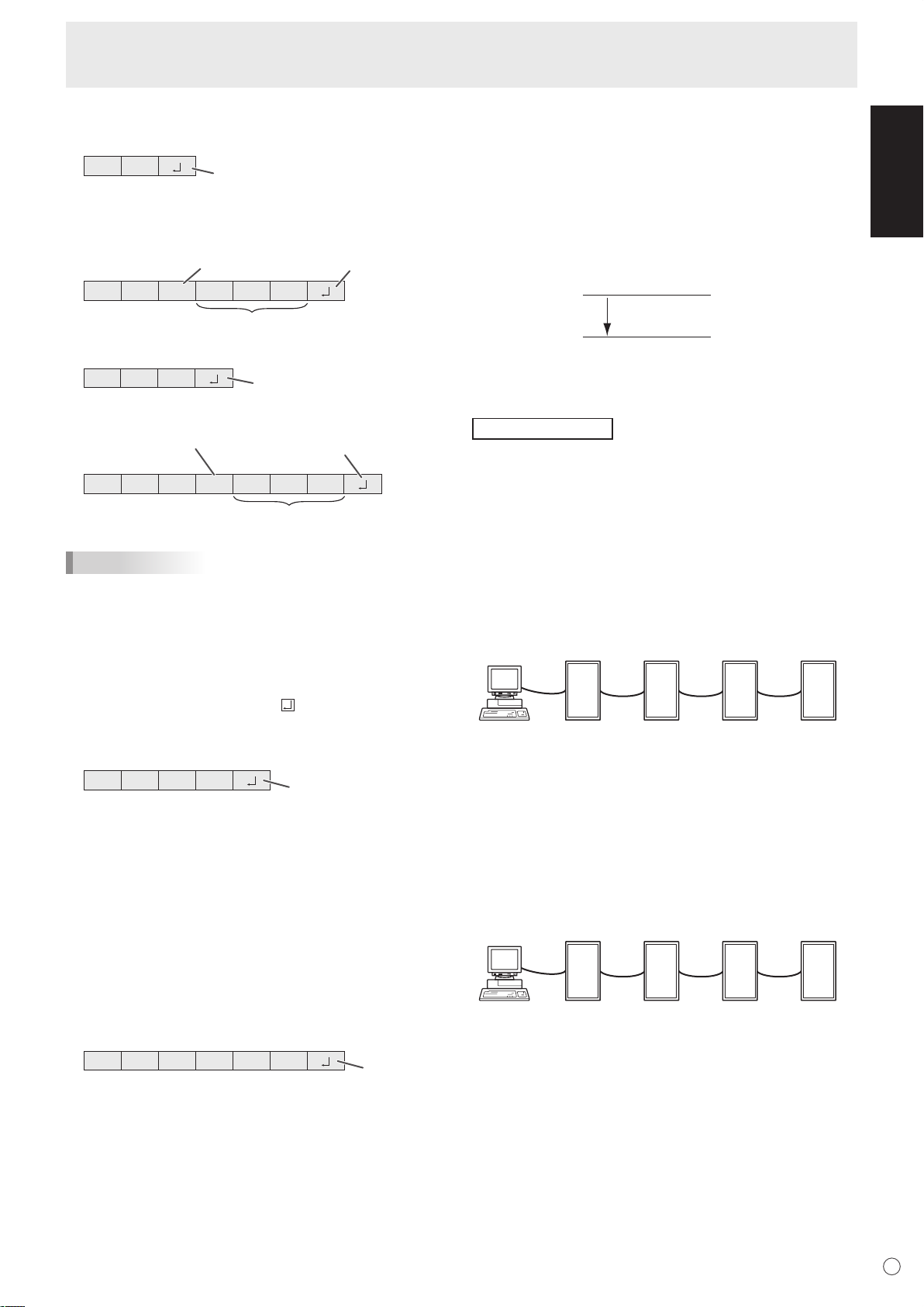
C1 C2 C3 C4 P1 P2 P3 P4
Return code
Command field
(4 prescribed
alphanumerical characters)
Parameter field
(4 character string comprised of:
0-9, +, -, space, ?)
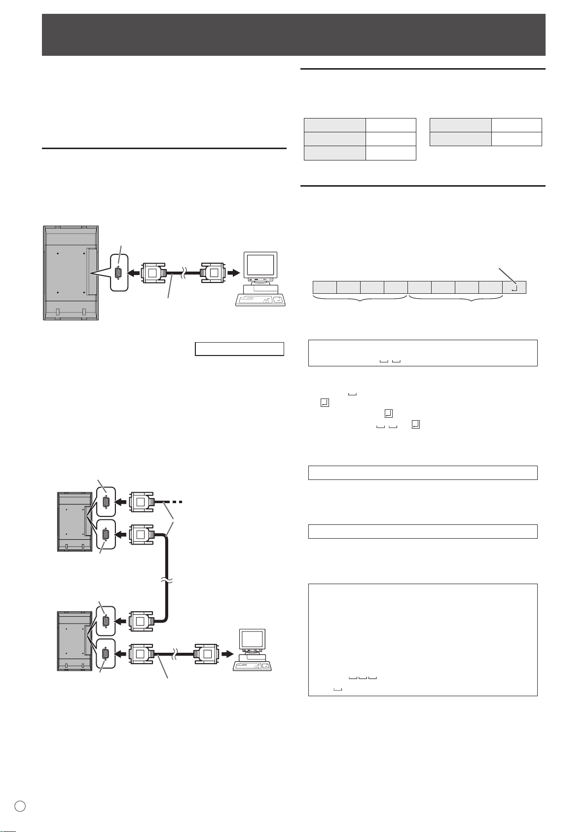
You can control this monitor from a PC via RS-232C (COM
port) on the PC.
You can also connect multiple monitors via a daisy chain by
using a PC. By assigning ID numbers to each monitor (see
page 25), you can make input mode selection/adjustment or
can check the status of a specific monitor.
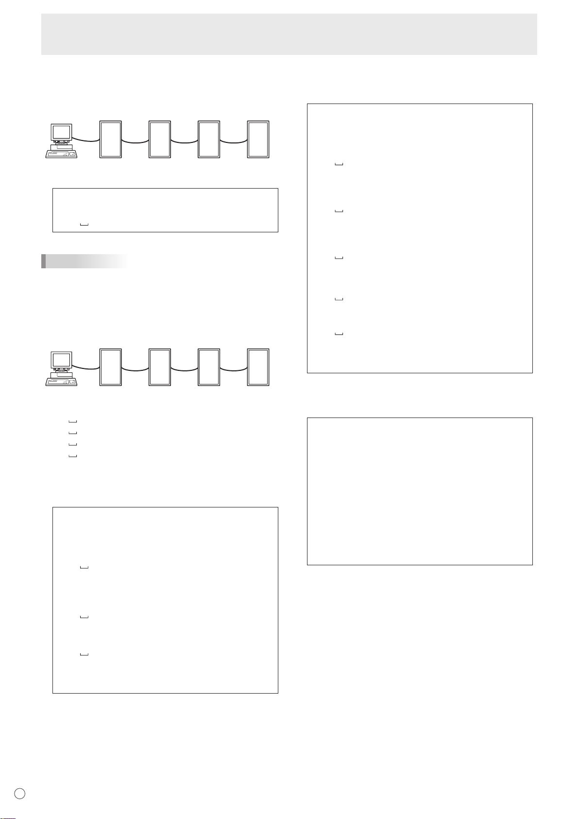
PC connection
One-to-one connection with a PC
Connect with RS-232 straight cable between the PC’s COM
port (RS-232C connector) and the RS-232C input terminal on
the monitor.
Daisy chain connection…
Connect with RS-232 straight cable between the PC’s COM
port (RS-232C connector) and the RS-232C input terminal on
the first monitor.
Next, connect RS-232 straight cable to the first monitor
RS-232C output terminal and to the second monitor’s
RS-232C input terminal. Connect in the same way to the third
and subsequent monitors.
Up to 25 monitors can be connected. (Depending on the
length of the cable used and the surrounding environment.)
Advanced operation
’s
Communication conditions
Set the RS-232C communication settings on the PC to match
the monitor’s communication settings as follows:
Baud rate 9600 bps
Data length 8 bits Flow control None
Parity bit None
Stop bit
1 bit
Communication procedure
Command format
When a command is sent from the PC to the monitor, the
monitor operates according to the received command and
sends a response message to the PC.
Example: VOLM0030
VOLM
* Be sure to input 4 characters for the parameter. Pad with
spaces (“ ”) if necessary.
(“ ” is a return code (0DH, 0AH or 0DH))
Wrong : VOLM30
Right : VOLM 30
When inputting a negative value, specify a numerical value in
three digits.
Example: AUTR-009
30
Do not use spaces for MPOS, DATE, and SC01 through
SC08. Specify parameters using a specified number of
characters.
Example: MPOS010097
If a command has “R” listed for “DIRECTION” in the
“RS-232C command table” on page 28, the current value can
be returned by using “?” as the parameter.
Example:
VOLM ? ? ? ? ←
30 ←
* If an ID number (see page 25) has been assigned
(For example, ID number = 1).
VOLM ? ←
30 001 ←
From PC to monitor (How much
is current volume setting?).
From monitor to PC (Current
volume setting: 30).
From PC to monitor.
From monitor to PC.
E
24
Page 27
Controlling the Monitor with a PC
O K
Return code
(0DH, 0AH)
O K SPC 0 0 1
ID number of responding monitor
Space (20H)
Return code
(0DH, 0AH)
R RE
Return code
(0DH, 0AH)
R RE SPC 0 0 1
ID number
Space (20H)
Return code
(0DH, 0AH)
IW TA
Return code
(0DH, 0AH)
EC DKOL
Return code
(0DH, 0AH)
VOLM0020
OK
INPS0001
WAIT
OK
Interval of 100 ms or more
[Example]
ID number: 1 ID number: 2 ID number: 3 ID number: 4
[Example]
ID number: 3 ID number: 2 ID number: 4 ID number: 1
Response code format
When a command has been executed correctly
A response is returned after a command is executed.
* If an ID number has been assigned
When a command has not been executed
* If an ID number has been assigned
TIPS
• “ERR” is returned when there is no relevant command or
when the command cannot be used in the current state of
the monitor.
• If communication has not been established for reasons
such as a bad connection between the PC and monitor,
nothing is returned (not even ERR).
• If no monitor has been assigned the designated ID number
(e.g. if the command IDSL0002 is used, but no monitor
with ID number: 2 is found), no response is returned.
If execution of the command is taking some time
Communication interval
• After OK or ERR is returned, you must send the following
commands.
To set a timeout for the command response, specify 10
seconds or longer.
• Provide an interval of 100 ms or more between the
command response and the transmission of the next
command.
Advanced operation
This section explains commands for daisy chain connection.
The basic communication procedure is the same as in the
“One-to-one connection with a PC” section.
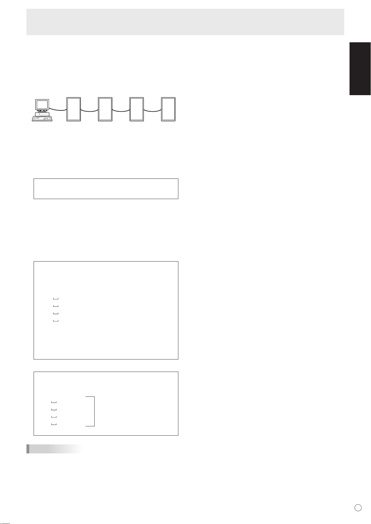
ID numbers
You can assign a unique ID number to each monitor (see
page 19). This allows you to control a particular monitor in a
daisy chain of monitors.
You can assign ID numbers either from the menu screen (using
the remote control) or from the PC using RS-232 cable.
If monitors are connected as shown above, you can
execute commands like “Set the volume of the monitor with
ID 4 to 20”.
ENGLISH
When the following commands are used, “WAIT” is returned.
In this case, a value will be returned if you wait a while. Do not
send any command during this period.
No ID number is attached to WAIT response.
• Commands which return WAIT:
1. When repeater control is used
2. When an IDSL or IDLK command is used
3. When one of the following commands is used: RSET,
INPS, ASNC, WIDE, EMAG, EPOS, PXSL, POWR,
AGIN, MWIN, MWIP, MWPP, ESTG
When control via RS-232C is locked (to prevent use) using
the operation lock function (see page 23)
When controlling monitors linked in a daisy chain by
designating ID numbers, you should basically avoid any
duplication of ID numbers.
ID numbers do not have to be assigned in ascending order
starting from the PC. They can also be connected as shown
below.
25
E
Page 28
Controlling the Monitor with a PC
ID number: 1 ID number: 2 ID number: 3 ID number: 4
[Example]
ID number: 1 ID number: 2 ID number: 3 ID number: 4
Commands for ID control
The command examples shown on this page assume the
following connection and ID number set up.
IDST ......... A monitor receiving this command sets its own ID
number in the parameter field.
Example:
IDST0001
OK 001 ←
TIPS
The ID number of this monitor is set to 1.
You can automatically assign ID numbers by using the IDST
command with the Repeater control (see “Repeater control”
on page 27).
For example, using the command “IDST001+” automatically
sets the ID numbers, as shown below.
IDLK ........
The parameter of this command sets the ID
number of the monitor. The monitor is subject to all
subsequent commands.
Example:
IDLK0002 ←
WAIT ←
OK 002 ←
VOLM0030 ←
WAIT ←
Following commands are for the monitor
with ID number: 2.
Searching for monitor with ID number: 2.
Found monitor with ID number: 2.
Sets volume of monitor with ID number:
2 to 30.*
Processing.
OK 002
VOLM0020 ←
Sets volume of monitor with ID number:
2 to 20.*
WAIT
OK 002
IDLK0000 ←
WAIT ←
OK 002 ←
Canceling fixed ID number setting.
Canceling IDLK.
Cancelation complete.
VOLM0010
The volume of the monitor with ID number: 1
OK 001 ←
(the one directly connected to the PC) is set
to 10. (IDLK is canceled.)
* The IDLK command remains effective until it is
canceled, or power is shut off.
IDST001 + ←
ID setting command with repeater control
WAIT
OK 001 ←
OK 002 ←
OK 003 ←
OK 004 ←
“OK” response from ID number: 1
“OK” response from ID number: 2
“OK” response from ID number: 3
“OK” response from ID number: 4 (End)
IDSL ........The parameter of this command sets the ID number
of the monitor. The monitor is subject to the next
command.
Example:
IDSL0002 ←
WAIT ←
OK 002 ←
VOLM0030 ←
WAIT ←
OK 002 ←
VOLM0020 ←
OK 001 ←
The next command is for the monitor with
ID number: 2.
Searching for monitor with ID number: 2.
Found monitor with ID number: 2.
Sets volume of monitor with ID number:
2 to 30.
Processing.
OK response from monitor with ID
number: 2.
Sets volume to 20.
The volume of the monitor with ID
number: 1 (the one directly connected
to the PC) is set to 20.*
* The IDSL command is effective only once, for the
immediately succeeding command.
IDCK ........Provides screen display of the ID number currently
assigned to a monitor, and the ID number currently
set for IDLK (if any).
Example:
(After executing IDLK0002)
IDCK0000
ID : 001 IDLK : 002
IDCK000 +
WAIT
ID : 001 IDLK : 000
ID : 002 IDLK : 000
ID : 003 IDLK : 000
ID : 004 IDLK : 000
(Parameter has no meaning.)
←
Returned response. The ID
number is also displayed on the
←
monitor screen.
Repeater control (If a command
←
is used with repeater control, ID
designation using IDSL or IDLK is
canceled.).
E
26
Page 29
Controlling the Monitor with a PC
[Example]
Set 1 Set 2 Set 3 Set 4
Repeater control
This system has a function to allow setting of multiple
monitors connected in a daisy chain using a single command.
This function is called repeater control. You can use Repeater
control function without assigning ID numbers.
* If monitors are connected as shown above, you can
execute a command like “Set all monitors’ input settings to
PC1 DIGITAL”.
Repeater control command
Repeater control is achieved by setting the FOURTH
CHARACTER of the parameter to “+”.
Example:
VOLM030 + ←
In repeater control, responses are returned by all the
connected monitors.
If you want to determine that a value has been returned by a
specific set, assign ID numbers to each monitor in advance.
When some monitors do not return their responses, the
probable cause is that the monitors could not receive the
command or command processing is not complete. Do not
send a new command.
Sets volume of all monitors to 30.
ENGLISH
Example: (When 4 monitors are connected, and
assigned ID numbers: 1 through 4.)
VOLM030 +
WAIT
OK 001
OK 002
OK 003
OK 004 ← If 4 monitors are connected in
a chain, reliable operation can
be ensured by sending a new
command only after a reply
has been returned by 4th (last)
monitor.
Repeater control can also be used for reading settings.
Example:
VOLM ? ? ? +
WAIT
10 001
20 002
30 003
30 004
Volume settings for all monitors
are returned.
TIPS
• If repeater control is used during ID designation (IDSL,
IDLK), the ID designation is canceled.
• Commands that use parameters consisting of more than
four characters can not be controlled by repeater control.
27
E
Page 30
Controlling the Monitor with a PC
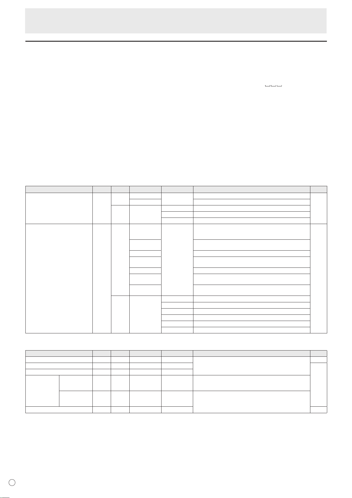
RS-232C command table
How to read the command table
Command: Command field (See page 24.)
Direction: W When the “Parameter” is set in the parameter field (see page 24), the command functions as described
under “Control/Response Contents”.
R The returned value indicated under “Reply” can be obtained by setting “????”, “
(repeater control) in the parameter field (see page 24).
Parameter: Parameter field (See page 24.)
Reply: Response (Returned value)
*: “Yes” indicates commands which can be used in power standby mode.
Power control/Input mode selection
Function
POWER CONTROL POWR W 0
INPUT MODE SELECTION
Command Direction
R 0 Standby mode
INPS W 0 Toggle change for input mode
R 1 PC1 DIGITAL
Parameter Reply Control/Response contents *
Switches to standby mode.
1 Returns from standby mode.
1 PC1 DIGITAL
2 PC2 ANALOG
3 AV2 COMPONENT
4 AV3 VIDEO
6 PC3 ANALOG
7 AV1 DIGITAL
1 Normal mode
2 Input signal waiting mode
Terminals not selected in DVI SELECT/BNC SELECT cannot be
selected.
“ERR” when AV (DIGITAL) is selected for DVI SELECT.
“ERR” when PC (ANALOG) is selected for BNC SELECT.
“ERR” when AV (COMPONENT) is selected for BNC SELECT.
“ERR” when PC (DIGITAL) is selected for DVI SELECT.
2 PC2 ANALOG
3 AV2 COMPONENT
4 AV3 VIDEO
6 PC3 ANALOG
7 AV1 DIGITAL
?” or “???+”
Yes
Yes
SCREEN menu (PC2/PC3)
Function
AUTO
CLOCK CLCK WR 0-255 0-255
PHASE PHSE WR 0-63 0-63
POSITIONING POSITION OF
RESET ARST W 1 No
E
28
THE LONGEST
DIRECTION
POSITION OF
THE SHORTEST
DIRECTION
Command Direction
ASNC W 1 No
HPOS WR 0-500 0-500 A maximum value depends on a resolution.
VPOS WR 0-100 0-100
Parameter Reply Control/Response contents *
No
Page 31

Controlling the Monitor with a PC
PICTURE menu
Function
AUTO
CONTRAST CONT WR 0-60 0-60 0-127 on PC2/PC3.
BLACK LEVEL BLVL WR 0-60 0-60 0-127 on PC2/PC3.
TINT TINT WR 0-60 0-60 When the input mode is AV.
COLORS COLR WR 0-60 0-60
SHARPNESS SHRP WR 0-24 0-24
ADVANCED FLESH TONE
3D-NR TDNR WR 0-2 0-2 0: OFF, 1: LOW, 2: HIGH
MPEG-NR MPNR WR 0-1 0-1 0: OFF, 1: ON
3D-Y/C YCSP WR 0-1 0-1 0: OFF, 1: ON
COLOR MODE BMOD WR 0 0 STD
WHITE BALANCE THRU CTMP WR 0 0 When the input mode is PC1.
PRESET 1-15 1-15 From 1: approximately 3,000K to 15: approximately 10,000K
USER 99 99
R-CONTRAST CRTR WR 0-512 0-512 “ERR” when CTMP is not set to 99.
G-CONTRAST CRTG WR 0-512 0-512
B-CONTRAST CRTB WR 0-512 0-512
GAMMA GAMM WR 0-2 0-2 0: 1.8, 1: 2.2, 2: 2.4 Yes
RESET ARST W 2 No
Command Direction
AGIN W 1 When the input mode is PC2, PC3. No
FLES WR 0-2 0-2 0: OFF, 1: LOW, 2: HIGH
Parameter Reply Control/Response contents *
2 2 VIVID
3 3 sRGB (When the input mode is PC)
(500K steps)
AUDIO menu
Function
TREBLE AUTR WR
BASS AUBS WR
BALANCE AUBL WR
RESET ARST W 3 No
Command Direction
Parameter Reply Control/Response contents *
-10-10 -10-10
-10-10 -10-10
-10-10 -10-10
ENGLISH
Yes
Yes
Yes
Yes
Yes
SETUP menu
Function
LANGUAGE LANG WR 14 14 ENGLISH
ID NUMBER ID NO. SETTING IDST W 0-255 Sets the monitor’s ID number. (“0” means “no ID number”.)
ID NO. SETTING
(ONCE)
ID NO. SETTING
(SUBSEQUENT)
ID CHECK IDCK W 0 ID : xxx
PICTURE FLIP PFIL WR 0-3 0-3 0: OFF, 1: MIRROR, 2: UPSIDE DOWN, 3: ROTATE Yes
Power On Delay PWOD WR 0 0 OFF
Command Direction
R 0-255 Returns the monitor’s ID number.
IDSL W 1-255 Sets a monitor ID number.
IDLK W 1-255 Sets a monitor ID number.
Parameter Reply Control/Response contents *
1 1 DEUTSCH
2 2 FRANÇAIS
3 3 ITALIANO
4 4 ESPAÑOL
5 5 РУССКИЙ
6 6
This ID number is only effective for the command immediately after this
command.
0 Clears the ID number if one has been designated.
This ID number is effective for the next and all subsequent commands
after this command.
0 Clears the ID number if one has been designated.
IDLK : yyy
1-60 1-60 ON
Displays monitor’s own ID number and the selected ID number on the
screen.
Yes
Yes
Yes
Yes
Yes
Yes
29
E
Page 32

Controlling the Monitor with a PC
OPTION menu
Function
DATE/TIME SETTING DATE
SCHEDULE SC01-
DVI SELECT DVSL WR 0-1 0-1 0: PC (DIGITAL), 1: AV (DIGITAL) Yes
BNC SELECT BNSL WR 0-1 0-1 0: PC (ANALOG), 1: AV (COMPONENT) Yes
QUICK SHOOT (PC)
QUICK SHOOT (AV) QSAV
COLOR SYSTEM CSYS WR 0-5 0-5 0: AUTO, 1: PAL, 2: PAL-60, 3: SECAM, 4: NTSC3.58, 5: NTSC4.43 Yes
AUDIO OUTPUT AOUT WR 0-1 0-1 0: VARIABLE, 1: FIXED Yes
INPUT
RESOLUTION
(PC)
INPUT
RESOLUTION
(AV)
SELF ADJUST
POWER MANAGEMENT PMNG WR 0-1 0-1 0: OFF, 1: ON Yes
RESOLUTION
CHECK
PIXEL SETTING
(PC2, PC3)
RESOLUTION
CHECK
Command Direction
WR
WR ABCDEFFGGH ABCDEFFGGH Schedule of a specified number
SC08
QSPC WR 0-1 0-1 0: OFF, 1: ON Yes
WR 0-1 0-1 0: OFF, 1: ON Yes
PXCK R - Returns current resolution in the form of hhh, vvv.
PXSL WR 1 1 V: 768) 1360 x 768
RESO R - 480i, 480p, 1080i, 720p, 1080p, VGA, etc.
AADJ WR 0-1 0-1 0: OFF, 1: ON Yes
Parameter Reply Control/Response contents *
AABBCCDDEE AABBCCDDEE
2 2 V: 768) 1280 x 768
3 3 V: 768) 1024 x 768
5 5 V: 480) 848 x 480
6 6 V: 480) 640 x 480
AA: Year, BB: Month, CC: Day, DD: Time, EE: Minute
A: Schedule 0 = Not effective, 1 = Effective
B: Power 0 = OFF, 1 = ON
C: Day of the week 1 0 = Only once, 1 = Every week, 2 = Every day
D: Day of the week 2 0 = Sunday, 1 = Monday through 6 = Saturday,
E: Day of the week 3 0 = Sunday, 1 = Monday through 6 = Saturday,
F: Time 00-23
G: Minute 00-59
H: Input 0 = Not specified, 1 = PC1/AV1, 2 = PC2,
9 = Not exist
9 = Not exist
3 = PC3/AV2, 4 = AV3
Yes
Yes
No
No
ENLARGE menu (When the input mode is PC)
Function
ENLARGE MODE EMAG WR 0-4 0-4 0: OFF, 1: 2 x 2, 2: 3 x 3, 3: 4 x 4, 4: 5 x 5
BEZEL WIDTH
IMAGE POSITION (2 x 2) EPOS WR 0-3 0-3 See page 21.
IMAGE POSITION (3 x 3) EPOS WR 0-8 0-8
IMAGE POSITION (4 x 4) EPOS WR 0-15 0-15
IMAGE POSITION (5 x 5) EPOS WR 0-24 0-24
ENLARGED
SCREEN
POSITIONING
ENLARGE/IMAGE POSITION SETTING ESTG WR XXYY XXYY XX: ENLARGE MODE (Same as EMAG), YY: IMAGE POSITION (Same
WIDTH OF THE
SHORTER
WIDTH OF THE
LONGER SIDE
THE LONGEST
DIRECTION
THE SHORTEST
DIRECTION
Command Direction
BEZH WR 0-100 0-100
SIDE
BEZV WR 0-100 0-100
EPSH WR -999-999 -999-999 The setting range depends on the ENLARGE MODE setting and the
EPSV WR -999-999 -999-999
Parameter Reply Control/Response contents *
IMAGE POSITION.
as EPOS)
PIP/PbyP menu
Function
PIP MODES
PIP SIZE
PIP POS THE LONGEST
PIP V/H-POS
PIP BLEND
PIP SOURCE
SOUND CHANGE MWAD WR 1-2 1-2 1: MAIN, 2: SUB Yes
MAIN POS (Main screen) MWPP WR 0-1 0-1 0: POS1, 1: POS2 Yes
PbyP2 POS (Sub screen) MW2P WR 0-2 0-2 0: POS3, 1: POS2, 2: POS1 Yes
AUTO OFF
DIRECTION
THE SHORTEST
DIRECTION
Command Direction
MWIN WR 0-3 0-3 0: OFF, 1: PIP, 2: PbyP, 3: PbyP2 Yes
MPSZ WR 1-12 1-12 Yes
MHPS W 0-100 Yes
R 0-100 Yes
MVPS W 0-100 Yes
R 0-100 Yes
MPOS W 0-100,0-100 Specify the position in MPOSxxxyyy format.
R 0-100,0-100 Returns a response in (xxx,yyy) format.
MWBL WR 0-15 0-15 Yes
MWIP WR 1 1 PC1 DIGITAL
MOFF WR 0-1 0-1 0: MANUAL, 1: AUTO Yes
Parameter Reply Control/Response contents *
(xxx: Longer side, yyy: Shorter side position)
(xxx: Longer side, yyy: Shorter side position)
2 2 PC2 ANALOG
3 3 AV2 COMPONENT
4 4 AV3 VIDEO
6 6 PC3 ANALOG
7 7 AV1 DIGITAL
No
Yes
Yes
Yes
E
30
Page 33

Controlling the Monitor with a PC
Initialisation/Functional Restriction Setting (FUNCTION) menu
Function
ALL RESET
ADJUSTMENT LOCK
OSD DISPLAY
LED OFLD WR 0-1 0-1 0: ON, 1: OFF Yes
Command Direction
RSET W 0 No
ALCK WR 0-2 0-2 0: OFF Yes
LOSD WR 0-1 0-1 0: ON, 1: OFF Yes
Parameter Reply Control/Response contents *
Others
Function
SCREEN SIZE (PC) WIDE WR 1-5 1-5 1: WIDE, 2: NORMAL, 3: DotbyDot, 4: ZOOM1, 5: ZOOM2 Yes
SCREEN SIZE (AV)
VOLUME VOLM WR 0-31 0-31 Yes
MUTE MUTE WR 0-1 0-1 0: OFF, 1: ON No
INFORMATION
BRIGHT VLMP WR 0-31 0-31 Brightness Yes
TEMPERATURE SENSOR DSTA
TEMPERATURE ACQUISITION ERRT
CAUSE OF LAST STANDBY MODE
MODEL INF1 R Value
SERIAL NO
Command Direction
WIDE WR 1-5 1-5 1: WIDE, 2: ZOOM1, 3: ZOOM2, 4: NORMAL, 5: DotbyDot Yes
SRNO R Value
R 0 Internal temperature normal
R Value Temperature at temperature sensors 1 through 3 are returned in the
STCA W 0 Initialisation
R 0 No detectable error has occurred
Parameter Reply Control/Response contents *
1 Internal temperature abnormal (Standby mode)
2 Internal temperature abnormal (Temperature is normal now, but it was
abnormal during operation.)
3 Internal temperature abnormal (Brightness of the backlight decreases.)
4 Temperature sensor abnormal
following forms:
[Sensor 1], [Sensor 2], [Sensor 3]
1 Standby mode by POWER button
2 Main power “OFF” by the main power switch
3 Standby mode by RS-232C
4 Waiting mode by No Signal (Incl: VESA DPMS/DMPM)
6 Standby mode by abnormal temperature
8 Standby mode by SCHEDULE setting
ENGLISH
Yes
Yes
Yes
Yes
31
E
Page 34

Troubleshooting
Before calling for repair services, make sure following checks
for possible remedies to the encountered symptoms.
There is no picture or sound.
• Is the power cord disconnected? (See page 12.)
• Is the main power switch set to “OFF”? (See page 14.)
• Is the monitor in standby mode (the power LED illuminating
in orange)? (See page 14.)
• Make sure correct input mode is selected. (See page 15.)
• If any external equipment is connected, make sure the
equipment is operating (playing back).
Remote control does not work.
• Are the batteries inserted with polarity (+,-) aligned? (See
page 12.)
• Are the batteries exhausted? (See page 12.)
• Point the remote control unit toward the monitor’s remote
control sensor. (See page 12.)
• Is the menu display hidden or is operation disabled?
page 23.)
Sound from left and right speakers is reversed.
Sound is heard from only one side.
• Are audio cables connected properly? (See pages 10 and
11.)
• Make sure audio cables for external speakers are
connected properly: left and right cables may be reversed
or one of the two cables may not be connected. (See page
11.)
• Check the setting of BALANCE for AUDIO menu. (See
page 18.)
There is a picture but no sound.
• Is the sound muted? (See page 15.)
• Make sure the volume is not set to minimum.
15.)
• Is the PC audio cable (commercially available) connected?
(See page 10.)
• Are audio cables connected properly? (See page 10.)
• Is the audio signal input properly to the audio input terminal
corresponding to the selected video input terminal? (See
page 15.)
Unstable video.
• The signal may be incompatible.
• Try the automatic screen adjustment when the PC2 input
terminal or PC3 input terminals is used. (See page 22.)
(See pages 10 and 34.)
(See
(See page
Power LED flashes red.
“SERVICE CALL” appears in the corner of the screen.
• Hardware has a problem. Turn off the monitor and request
repair from your SHARP dealer.
When “TEMPERATURE” is displayed.
• When the internal temperature of the monitor rises
excessively, the brightness of the backlight decreases
in order to prevent high-temperature-related problems.
Remove the cause of the excessive rise in temperature.
(See the description below.)
The monitor sometimes makes a cracking sound.
• You may hear cracking sound from the monitor. This
happens when the cabinet slightly expands and contracts
according to change in temperature. This does not affect
the monitor’s performance.
■ Warning when temperature rises
• When the internal temperature of the monitor rises
excessively, the brightness of the backlight decreases
automatically in order to prevent high-temperaturerelated problems. When this occurs, “TEMPERATURE” is
displayed on the screen and the Power LED flashes red
and green alternately.
• If the internal temperature rises further, the monitor
automatically enters standby mode. (The Power LED
continues flashing red and green alternately.)
Solution:
• If the monitor enters standby mode due to a rise in
temperature, to return to normal display, turn the main
power switch off and then back on again. The monitor,
however, will enter standby mode again if the cause of the
temperature rise is not eliminated. (See page 9.)
• Check whether the monitor is placed at a location where a
quick rise in temperature is likely. Internal temperature rises
quickly if the vents on the monitor are blocked.
• Internal temperature rises quickly if dust accumulates inside
the monitor or around the vents. Remove dust if possible.
Ask Sharp dealer about removing internal dust.
PC1 or AV1 does not appear properly.
• Is the setting of DVI SELECT correct? (See page 19.)
• Is the input signal compatible with this monitor? (See pages
10 and 34.)
• Turn off the power to the connected equipment and then
turn the power on again.
• If the monitors are connected in a daisy chain, turn off the
power to all the monitors connected in a daisy chain and
then turn the power on again.
PC3 or AV2 does not appear properly.
• Is the setting of BNC SELECT correct? (See page 19.)
• Is the input signal compatible with this monitor? (See page
34.)
Control buttons do not work.
There is no picture.
• Some kind of load noises from outside might interfere with
normal operation. Turn off the power and turn it on after
waiting at least 5 seconds, and then check the operation.
E
32
Page 35

Specifications
Model PN-G655RE
LCD element 65" wide (163.9 cm diagonal) ASV low-reflection black TFT LCD
Max. resolution (pixels) 1080 x 1920
Max. colours 16.77 M colours (8 bits/colour)
Pixel pitch 0.744 mm (H) x 0.744 mm (V)
Vi
ewing angle 176° right/left/up/down (contrast ratio ≥ 10)
Screen active area (mm) 804 x 1428
Computer input signal Digital (DVI 1.0 standard-compliant), Analogue RGB (0.7 Vp-p) [75 Ω]
S
ync signal Horizontal/vertical separate (TTL: positive/negative), Sync-on-green,
Composite sync (TTL: positive/negative)
Vi
deo colour system PAL, PAL-60, SECAM, NTSC (3.58 MHz), NTSC (4.43 MHz)
Plug and play VESA DDC2B
Power management VESA DPMS, DVI DMPM
Input terminals PC/AV Digital DVI-D 24 pin (HDCP compatible) x 1
PC Analogue Mini D-sub 15 pin, 3 rows x 1, BNC
*1*2
x 1
Audio 3.5 mm mini stereo jack x 1
AV
Composite video BNC x 1
Component BNC (Y, Cb/Pb, Cr/Pr)*1 x 1
Audio RCA pin (L/R) x 1
Serial (RS-232C) D-sub 9 pin x 1
Output terminals PC/AV Digital DVI-D 24 pin x 1
*3
Audio RCA pin (L/R) x 1
Serial (RS-232C) D-sub 9 pin x 1
Speaker 7 W + 7 W [6 Ω]
Power requirement AC 100 V - 240 V, 50 / 60 Hz
Operating temperature 0°C to 40°C
Operating humidity 20% to 80% (no condensation)
Power consumption 560 W (Input signal waiting mode: 10 W, Standby mode: 4.0 W)
Dimensions (mm) Approx. 923 x 150 x 1,572 (excluding protrusions)
Weight (kg) Approx. 66 (excluding the temporary stand)
Product Specifications
ENGLISH
*1 Cannot be used simultaneously.
*2 Does not support plug and play.
*3 Connection is allowed with an HDCP-compatible device only. Does not support Repeater control function.
As a part of our policy of continuous improvement, SHARP reserves the right to make design and specification changes for
product improvement without prior notice. The performance specification figures indicated are nominal values of production
units. There may be some deviations from these values in individual units
.
33
E
Page 36

VESA
Wide
US TEXT
Sun
Screen resolution Hsync Vsync Dot frequency
Analogue signal
640 x 480
800 x 600
848 x 480
1024 x 768
1152 x 864
1280 x 768
1280 x 960
1280 x 1024
1360 x 768
1600 x 1200
*1
1280 x 720
1920 x 1080
720 x 400
1024 x 768
11
52 x 900
1280 x 1024
1600 x 1000
31.5 kHz
37.9 kHz
37.5 kHz
35.1 kHz
37.9 kHz
48.1 kHz
46.9 kHz
31.0 kHz
48.4 kHz
56.5 kHz
60.0 kHz
67.5 kHz
47.8 kHz
60.3 kHz
60.0 kHz
64.0 kHz
80.0 kHz
47.7 kHz
75.0 kHz
44.7 kHz
66.3 kHz
31.5 kHz
48.3 kHz
53.6 kHz
56.6 kHz
61.8 kHz
71.8 kHz
71.7 kHz
81.1 kHz
68.6 kHz
60 Hz
72 Hz
75 Hz
56 Hz
60 Hz
72 Hz
75 Hz
60 Hz
60 Hz
70 Hz
75 Hz
75 Hz
60 Hz
75 Hz
60 Hz
60 Hz
75 Hz
60 Hz
60 Hz
60 Hz
60 Hz
70 Hz
60 Hz
66 Hz
70 Hz
66 Hz
76.2 Hz
67.2 Hz
76 Hz
66 Hz
25.175 MHz
31.5 MHz
31.5 MHz
36.0 MHz
40.0 MHz
50.0 MHz
49.5 MHz
33.75 MHz
65.0 MHz
75.0 MHz
78.75 MHz
108.0 MHz
79.5 MHz
102.25 MHz
108.0 MHz
108.0 MHz
135.0 MHz
85.5 MHz
162.0 MHz
74.4 MHz
148.5 MHz
28.3 MHz
64.13 MHz
70.4 MHz
74.25 MHz
94.88 MHz
108.23 MHz
117.01 MHz
134.99 MHz
135.76 MHz
Ye
s
Ye
s
Ye
s
Ye
s
Ye
s
Ye
s
Ye
s
Ye
s
Ye
s
Ye
s
Ye
s
Ye
s
Ye
s
Ye
s
Ye
s
Ye
s
Ye
s
Ye
s
Ye
s
Ye
s
Ye
s
Ye
s
Ye
s
Ye
s
Ye
s
Ye
s
Ye
s
Ye
s
Ye
s
Ye
s
Digital signal
Yes
Ye
s
Ye
s
Yes
Ye
s
Ye
s
Ye
s
Ye
s
Ye
s
Ye
s
Ye
s
Ye
s
Ye
s
Ye
s
Ye
s
Ye
s
Ye
s
Ye
s
Ye
s
Ye
s
Ye
s
-
-
-
-
-
-
-
-
*1 Displays a reduced image.
Specifications
Unit: mm
Opening width
(807)
871
Opening height (1432)
1572
150
40 40
1509
440
1003
923
650
Screw holes for mounting brackets
Dimensional Drawings
Note that the values shown are approximate values.
When mounting the monitor, read the
manual of the brackets or stand for their
mounting procedure. The screw holes for
mounting brackets (M10 x 4 holes) are
provided on the rear of the monitor.
Note that screw hole depth of the monitor
is 30 mm. Loose holding may cause the
product to fall, resulting in serious personal
injuries as well as damage to the product.
The screw and hole should come together
with over 20 mm length of thread. Use the
bracket which can endure at least 4 times
or more the weight of the monitor.
Compatible signal timing (PC)
* All are compliant only with non-interlaced.
* Depending on the connected PC, images may not be displayed properly even if the compatible signal described above is input.
* The frequency values for the Sun are reference values. A separate conversion adapter (commercially available) may be required for
connecting the monitor to the Sun.
E
34
Page 37

Specifications
No.
1
2
3
4
5
6
7
8
9
10
11
12
Function
TMDS data 2TMDS data 2+
TMDS data 2/4 shield
N.C.
N.C.
DDC clock
DDC data
N.C.
TMDS data 1TMDS data 1+
TMDS data 1/3
shield
N.C.
No.
13
14
15
16
17
18
19
20
21
22
23
24
Function
N.C.
+5 V
GND
Hot-plug detection
TMDS data 0TMDS data 0+
TMDS data 0/5 shield
N.C.
N.C.
TMDS clock shield
TMDS clock+
TMDS clock-
No.
1
2
3
4
5
Function
N.C.
Transmitted data
Received data
N.C.
GND
No.
6
7
8
9
Function
N.C.
N.C.
N.C.
N.C.
No.
1
2
3
4
5
Function
N.C.
Received data
Transmitted data
N.C.
GND
No.
6
7
8
9
Function
N.C.
N.C.
N.C.
N.C.
No.
1
2
3
4
5
6
7
8
Function
Red video signal input
Green video signal input
Blue video signal input
N.C.
GND
GND for red video signal
GND for green video signal
GND for blue video signal
No.
9
10
11
12
13
14
15
Function
+5 V
GND
N.C.
DDC data
Hsync signal input
Vsync signal input
DDC clock
No.
1
2
3
4
5
6
7
8
9
10
11
12
Function
TMDS data 2TMDS data 2+
TMDS data 2/4 shield
N.C.
N.C.
DDC clock
DDC data
N.C.
TMDS data 1TMDS data 1+
TMDS data 1/3
shield
N.C.
No.
13
14
15
16
17
18
19
20
21
22
23
24
Function
N.C.
+5 V
GND
Hot-plug detection
TMDS data 0TMDS data 0+
TMDS data 0/5 shield
N.C.
N.C.
TMDS clock shield
TMDS clock+
TMDS clock-
DPMS
ON STATE
STANDBY
SUSPEND
OFF STATE
Screen
Display
No
display
Power
consumption
560 W
10 W
Hsync
Ye
s
No
Ye
s
No
Vsync
Ye
s
Ye
s
No
No
DMPM
Monitor ON
Active OFF
Screen
Display
No display
Power
consumption
560 W
10 W
Power management
This monitor conforms to VESA DPMS and DVI DMPM. Both your video card and computer must support the same standard in
order for the monitor’s power management function to work.
DPMS: Display Power Management Signaling DMPM: Digital Monitor Power Management
DDC (plug and play)
The monitor supports the VESA DDC (Display Data Channel) standard.
DDC is a signal standard for plug and play between monitors and computers. Information about resolution and other parameters
is exchanged between the two. This function can be used if the computer supports DDC and it has been configured to detect
plug-and-play monitors.
There are several types of DDC, depending on the communication method used. This monitor supports DDC2B.
PC1/AV1 input terminal pins
(DVI-D24 pin)
PC2 input terminal pins
(Mini D-sub 15 pin)
ENGLISH
RS-232C input terminal pins
(D-sub 9 pin)
RS-232C output terminal pins
(D-sub 9 pin)
PC/AV output terminal pins
(DVI-D24 pin)
35
E
Page 38

M E M O
E
36
Page 39

PN-G655RE
LCD FARBMONITOR
DEUTSCH
WICHTIGE INFORMATIONEN
ACHTUNG:
VORSICHT: ABDECKUNG NICHT ENTFERNEN:
HALTEN SIE DAS GERÄT VON REGEN UND JEGLICHER ART
VON FEUCHTIGKEIT FERN, UM DIE GEFAHR VON BRAND ODER
STROMSCHLAG ZU VERRINGERN.
VORSICHT
ELEKTROSCHOCKGEFAHR
NICHT ÖFFNEN
GEFAHR VON ELEKTROSCHOCK.
KEINE WARTUNGSTEILE IM INNEREN.
SERVICEARBEITEN NUR VON
QUALIFIZIERTEM FACHPERSONAL
DURCHFÜHREN LASSEN.
DEUTSCH
Das Blitzsymbol innerhalb eines gleichseitigen
Dreiecks weist den Benutzer auf das
Vorhandensein nicht isolierter “gefährlicher
Spannung” im Geräteinneren hin, die ausreichend
groß ist, um einen Elektroschock hervorzurufen.
Das Rufzeichen innerhalb eines Dreiecks
weist den Benutzer auf wichtige Betriebs- und
Wartungs- bzw. Serviceanweisungen in der
Produktdokumentation hin.
VORSICHT:
VORSICHT:
Dieses Gerät ist mit Leuchtstoffröhren ausgestattet, die geringe Mengen an Quecksilber enthalten.
Die Entsorgung dieser Materialien unterliegt in manchen Ländern verschiedenen Umweltschutzvorschriften.
Informationen zu Entsorgung oder Recycling erhalten Sie von den Behörden Ihres Landes.
Die Wandsteckdose sollte sich in der Nähe des Gerätes befinden und leicht zugänglich sein.
Das mitgelieferte Netzkabel darf unter keinen Umständen verändert oder modifiziert werden.
1
D
Page 40

WICHTIGE INFORMATIONEN (Fortsetzung)
Achtung: Ihr Produkt trägt dieses Symbol. Es besagt, dass Elektro- und Elektronikgeräte nicht mit dem
Haushaltsmüll entsorgt, sondern einem getrennten Rücknahmesystem zugeführt werden sollten.
A. Entsorgungsinformationen für Benutzer aus Privathaushalten
1. In der Europäischen Union
Achtung: Werfen Sie dieses Gerät zur Entsorgung bitte nicht in den normalen Hausmüll!
Gemäß einer neuen EU-Richtlinie, die die ordnungsgemäße Rücknahme, Behandlung und Verwertung von gebrauchten
Elektro- und Elektronikgeräten vorschreibt, müssen elektrische und elektronische Altgeräte getrennt entsorgt werden.
Nach der Einführung der Richtlinie in den EU-Mitgliedstaaten können Privathaushalte ihre gebrauchten Elektro- und
Elektronikgeräte nun kostenlos an ausgewiesenen Rücknahmestellen abgeben*. In einigen Ländern* können Sie Altgeräte
u.U. auch kostenlos bei Ihrem Fachhändler abgeben, wenn Sie ein vergleichbares neues Gerät kaufen.
*) Weitere Einzelheiten erhalten Sie von Ihrer Gemeindeverwaltung.
Wenn Ihre gebrauchten Elektro- und Elektronikgeräte Batterien oder Akkus enthalten, sollten diese vorher entnommen und
gemäß örtlich geltenden Regelungen getrennt entsorgt werden.
Durch die ordnungsgemäße Entsorgung tragen Sie dazu bei, dass Altgeräte angemessen gesammelt, behandelt
und verwendet werden. Dies verhindert mögliche schädliche Auswirkungen auf Umwelt und Gesundheit durch eine
unsachgemäße Entsorgung.
2. In anderen Ländern außerhalb der EU
Bitte erkundigen Sie sich bei Ihrer Gemeindeverwaltung nach dem ordnungsgemäßen Verfahren zur Entsorgung dieses
Geräts.
Für die Schweiz: Gebrauchte Elektro- und Elektronikgeräte können kostenlos beim Händler abgegeben werden, auch wenn
Sie kein neues Produkt kaufen. Weitere Rücknahmesysteme finden Sie auf der Homepage von www.swico.ch oder
www.sens.ch.
B. Entsorgungsinformationen für gewerbliche Nutzer
1. In der Europäischen Union
Wenn Sie dieses Produkt für gewerbliche Zwecke genutzt haben und nun entsorgen möchten:
Bitte wenden Sie sich an Ihren SHARP Fachhändler, der Sie über die Rücknahme des Produkts informieren kann.
Möglicherweise müssen Sie die Kosten für die Rücknahme und Verwertung tragen. Kleine Produkte (und kleine Mengen)
können möglicherweise bei Ihrer örtlichen Rücknahmestelle abgegeben werden.
Für Spanien: Bitte wenden Sie sich an das vorhandene Rücknahmesystem oder Ihre Gemeindeverwaltung, wenn Sie
Fragen zur Rücknahme Ihrer Altgeräte haben.
2. In anderen Ländern außerhalb der EU
Bitte erkundigen Sie sich bei Ihrer Gemeindeverwaltung nach dem ordnungsgemäßen Verfahren zur Entsorgung dieses
Geräts.
D
2
Page 41

VEREHRTE KUNDIN, VEREHRTER KUNDE
Wir danken Ihnen für den Kauf eines SHARP LCD-Gerätes. Um Ihre Sicherheit sowie einen jahrelangen, störungsfreien Betrieb
dieses Produkts zu gewährleisten, lesen Sie bitte den Abschnitt “Sicherheitsvorkehrungen” vor der Verwendung des Produkts
durch.
SICHERHEITSVORKEHRUNGEN
Elektrizität erfüllt viele nützliche Aufgaben, kann aber auch Personen- und Sachschäden verursachen, wenn sie unsachgemäß
gehandhabt wird. Dieses Produkt wurde mit Sicherheit als oberster Priorität konstruiert und hergestellt. Dennoch besteht bei
unsachgemäßer Handhabung u.U. Stromschlag- und Brandgefahr. Um mögliche Gefahren zu vermeiden, befolgen Sie beim
Aufstellen, Betreiben und Reinigen des Produkts bitte die nachstehenden Anleitungen. Lesen Sie im Interesse Ihrer eigenen
Sicherheit sowie einer langen Lebensdauer des LCD-Gerätes zunächst die nachstehenden Hinweise durch, bevor Sie das
Produkt in Verwendung nehmen.
1. Bedienungsanleitungen lesen — Nehmen Sie das Produkt erst in Betrieb, nachdem Sie alle diesbezüglichen Hinweise
gelesen und verstanden haben.
2. Bedienungsanleitung aufbewahren — Diese Bedienungsanleitung mit den Sicherheits- und Bedienungshinweisen sollte
aufbewahrt werden, damit Sie im Bedarfsfall jederzeit darauf zurückgreifen können.
3. Warnungen beachten — Alle Warnungen auf dem Gerät und in den Bedienungsanleitungen sind genauestens zu beachten.
4. Anleitungen befolgen — Alle Anleitungen zur Bedienung müssen befolgt werden.
5. Reinigung — Ziehen Sie vor dem Reinigen des Produkts das Netzkabel. Reinigen Sie das Gerät mit einem trockenen Tuch.
Verwenden Sie keine flüssigen Reiniger oder Aerosol-Sprays.
6. Zusatzgeräte und Zubehör — Verwenden Sie ausschließlich vom Hersteller empfohlenes Zubehör. Bei Verwendung anderer
Zusatzgeräte bzw. Zubehörteile besteht evtl. Unfallgefahr.
7. Wasser und Feuchtigkeit — Benutzen Sie das Gerät nicht in der Nähe von Wasser.
8. Belüftung — Die Belüftungsschlitze und andere Öffnungen im Gehäuse dienen der Belüftung des Geräts.
Halten Sie diese Öffnungen unbedingt frei, da eine unzureichende Belüftung zu einer Überhitzung bzw. Verkürzung der
Lebensdauer des Produkts führen kann. Stellen Sie das Gerät nicht auf ein Sofa, einen Lappen oder ähnliche Oberflächen,
da die Belüftungsschlitze dadurch blockiert werden können. Stellen Sie das Gerät auch nicht in ein umschlossenes
Gehäuse, wie z.B. in ein Bücherregal oder einen Schrank, sofern dort nicht für eine ausreichende Belüftung gesorgt ist oder
die Anweisungen des Herstellers befolgt werden.
9. Netzkabel-Schutz — Die Netzkabel sind so zu verlegen, dass sie vor Tritten geschützt sind und keine schweren Objekte
darauf abgestellt werden.
10. Das LCD-Panel ist ein Glasprodukt. Es kann daher brechen, wenn es zu Boden fällt oder einen Schlag oder Stoß erhält.
Achtung: bei einem Bruch des LCD-Panels besteht durch die Glasstücke Verletzungsgefahr.
11. Überlastung — Vermeiden Sie eine Überlastung von Netzsteckdosen und Verlängerungskabeln. Bei Überlastung besteht
Brand- und Stromschlaggefahr.
12. Eindringen von Gegenständen und Flüssigkeiten — Schieben Sie niemals irgendwelche Gegenstände durch die
Gehäuseöffnungen in das Innere des Geräts. Im Produkt liegen hohe Spannungen vor. Durch das Einschieben von
Gegenständen besteht Stromschlaggefahr bzw. die Gefahr von Kurzschlüssen zwischen den Bauteilen.
Aus demselben Grunde dürfen auch keine Flüssigkeiten auf das Gerät verschüttet werden.
13. Wartung — Versuchen Sie auf keinen Fall, selbst Wartungsarbeiten am Gerät durchzuführen. Durch das Entfernen von
Abdeckungen setzen Sie sich hohen Spannungen und anderen Gefahren aus. Lassen Sie sämtliche Wartungsarbeiten
ausschließlich von qualifiziertem Service-Personal ausführen.
14. Reparaturen — Ziehen Sie in den folgenden Situationen sofort das Netzkabel und lassen Sie das Produkt von qualifiziertem
Service-Personal reparieren:
a. Wenn das Netzkabel oder der Netzstecker beschädigt ist.
b. Wenn Flüssigkeit in das Gerät eingedrungen ist oder Gegenstände in das Gerät gefallen sind.
c. Wenn das Gerät nass geworden ist (z.B. durch Regen).
d. Wenn das Gerät nicht wie in der Bedienungsanleitung beschrieben funktioniert.
Nehmen Sie nur die in den Bedienungsanleitungen beschriebenen Einstellungen vor. Unsachgemäße Einstellungen an
anderen Reglern können zu einer Beschädigung führen und machen häufig umfangreiche Einstellarbeiten durch einen
qualifizierten Service-Techniker erforderlich.
e. Wenn das Produkt fallen gelassen oder beschädigt wurde.
f. Wenn das Gerät einen anormalen Zustand aufweist. Jedes erkennbare anormale Verhalten zeigt an, dass der
Kundendienst erforderlich ist.
DEUTSCH
3
D
Page 42

SICHERHEITSVORKEHRUNGEN (Fortsetzung)
15. Ersatzteile — Wenn Ersatzteile benötigt werden, stellen Sie bitte sicher, dass der Service-Techniker nur die vom Hersteller
bezeichneten Teile oder Teile mit gleichen Eigenschaften und gleichem Leistungsvermögen wie die Originalteile verwendet.
Die Verwendung anderer Teile kann zu einem Brand, zu Stromschlag oder anderen Gefahren führen.
16. Sicherheitsüberprüfungen — Lassen Sie vom Service-Techniker nach Service- oder Reparaturarbeiten eine
Sicherheitsüberprüfung vornehmen, um sicherzustellen, dass das Produkt in einem einwandfreien Betriebszustand ist.
17. Wandmontage — Bei der Montage des Gerätes an der Wand ist sicherzustellen, dass die Befestigung nach der vom
Hersteller empfohlenen Methode erfolgt.
18. Wärmequellen — Stellen Sie das Produkt nicht in der Nähe von Heizkörpern, Heizgeräten, Öfen oder anderen Geräten (wie
z.B. Verstärkern) auf, die Hitze abstrahlen.
19. Bei der Verwendung des Monitors ist darauf zu achten, dass Gefahren für Leib und Leben, Schäden an Gebäuden und
anderen Gegenständen sowie eine Beeinflussung von wichtigen oder gefährlichen Geräten, wie z.B. der
Nuklearreaktionssteuerung in Atomanlagen, lebenserhaltenden Geräten in medizinischen Einrichtungen oder
Raketenabschusssteuerungen in Waffensystemen vermieden werden.
ACHTUNG:
Dieses Gerät ist ein Produkt der Klasse A. In Wohnräumen kann dieses Gerät Störsignale erzeugen, die durch
entsprechende Abhilfemaßnahmen beseitigt werden müssen.
ACHTUNG:
Verwenden Sie den werkseitig montierten temporären Fuß nicht für die endgültige Installation des LCD-Monitors.
Dieser Fuß darf nur solange verwendet werden, bis der Monitor richtig montiert wurde.
Der temporäre Fuß kann den LCD-Monitor nicht sicher tragen. Die Verwendung des temporären Fußes kann zu
Verletzungen führen.
D
4
Page 43

TIPPS UND SICHERHEITSHINWEISE
- Bei der Herstellung des TFT Farb-LCD-Panels dieses
Monitors wurde Präzisionstechnologie eingesetzt Trotzdem
können einzelne Punkte am Bildschirm überhaupt nicht
leuchten oder ständig leuchten. Bei Betrachtung des
Bildschirms aus einem spitzen Winkel können die Farben
oder die Helligkeit unregelmäßig erscheinen. Bitte beachten
Sie, dass es sich dabei um keine Qualitätsmängel handelt,
sondern um allgemein bei LCD-Geräten auftretende
Phänomene, welche die Leistung des Monitors in keiner
Weise beeinträchtigen.
- Lassen Sie niemals ein Standbild über längere Zeit hinweg
anzeigen, da dies ein Nachleuchten am Bildschirm zur Folge
haben könnte.
- Vermeiden Sie es, den Monitor mit harten Gegenständen
abzureiben oder zu berühren.
- Wir bitten um Ihr Verständnis, dass Sharp über die gesetzlich
anerkannte Leistungshaftung hinaus keine Haftung für
Fehler übernimmt, die sich aus der Verwendung durch den
Kunden oder einen Dritten ergeben, und auch nicht für
sonstige Funktionsstörungen oder Schäden, die während
der Verwendung am Gerät entstehen.
- Eine Aktualisierung dieses Monitors und seines Zubehörs ist
vorbehalten.
- Verwenden Sie den Monitor nicht an Orten mit hoher
Staubentwicklung, hoher Luftfeuchtigkeit oder an Orten, an
denen der Monitor mit Öl oder Dampf in Kontakt kommen
könnte, da dies zu einem Brand führen könnte.
- Achten Sie darauf, dass der Monitor nicht mit Wasser oder
anderen Flüssigkeiten in Berührung kommt. Achten Sie auch
darauf, keine Gegenstände, wie z.B. Büroklammern oder
sonstige spitze Gegenstände, in den Monitor zu stecken. Die
Folge könnte ein Brand oder Stromschlag sein.
- Stellen Sie den Monitor nicht auf instabile Gegenstände oder
an andere unsichere Stellen. Setzen Sie den Monitor keinen
starken Stößen oder Erschütterungen aus. Wenn der Monitor
hinunterfällt oder umkippt, könnte er Schaden nehmen.
- Stellen Sie den Monitor nicht in der Nähe von Heizungen
oder an anderen Stellen auf, an denen hohe Temperaturen
auftreten, da dies zu einer übermäßig starken Erhitzung mit
der Folge eines Brandes führen könnte.
- Der Monitor kann Bilder nicht selbst auf Portrait-Format
drehen. Der Bildschirminhalt muss daher bereits von der
Bildquelle vertikal verlängert.
Das Netzkabel
- Beschädigen Sie das Netzkabel nicht, stellen Sie
keine schweren Gegenstände darauf, und überdehnen
oder knicken Sie es nicht. Verwenden Sie keine
Verlängerungskabel. Ein beschädigtes Kabel kann einen
Brand oder Stromschlag verursachen.
- Verwenden Sie nur das mit dem Monitor gelieferte
Netzkabel.
- Stecken Sie den Netzstecker direkt in die Netzsteckdose.
Die Verwendung eines Verlängerungskabels kann aufgrund
von Überhitzung zu einem Brand führen.
- Achten Sie darauf, dass Sie beim Einstecken oder
Ausstecken des Netzsteckers keine nassen Hände haben,
um einen Elektroschlag zu vermeiden.
- Ziehen Sie das Netzkabel aus der Steckdose, wenn Sie das
Gerät längere Zeit über nicht verwenden.
- Führen Sie keine Reparaturversuche an einem beschädigten
oder nicht funktionstüchtigen Netzkabel durch. Überlassen
Sie Reparaturarbeiten ausschließlich dem Kundendienst.
Inhalt der Bedienungsanleitung
- Microsoft und Windows sind eingetragene Warenzeichen der
Microsoft Corporation.
- Dieses Produkt wird mit RICOH Bitmap Fonts geliefert,
die von RICOH COMPANY, LTD produziert und vertrieben
werden.
- Alle andere Warenzeichen und Produktnamen sind Eigentum
der jeweiligen Gesellschaften.
- Die in dieser Bedienungsanleitung verwendeten Beispiele
beziehen sich auf das englischsprachige OSD-Menü.
- Die Abbildungen in dieser Bedienungsanleitung zeigen
nicht immer das vorliegende Gerät oder die jeweilige
Bildschirmanzeige.
Leuchtstoffröhre
● Die in diesem Gerät enthaltenen Leuchtstoffröhren haben
eine beschränkte Lebensdauer.
● Aufgrund der Eigenschaften der Leuchtstoffröhren kann
der Bildschirm während der ersten Zeit flackern. Wenn dies
der Fall ist, schalten Sie bitte den Hauptnetzschalter am
Monitor aus und wieder ein.
DEUTSCH
5
D
Page 44

Inhalt
Einleitung
WICHTIGE INFORMATIONEN ..........................................1
VEREHRTE KUNDIN, VEREHRTER KUNDE ..................3
SICHERHEITSVORKEHRUNGEN ....................................3
TIPPS UND SICHERHEITSHINWEISE .............................5
Mitgeliefertes Zubehör ....................................................7
Teilebezeichnungen .........................................................
Vorderansicht ...............................................................
Rückansicht ..................................................................8
Fernbedienung .............................................................8
Anschluss und Installation
Aufstellen des Monitors ..................................................9
Wichtige Hinweise zur Befestigung ..............................9
Anschließen von Zusatzgeräten ...................................10
Verbindung mit PC .....................................................
Verbindung mit AV-Geräten ........................................
Andere Anschlüsse ....................................................
Anschließen externer Lautsprecher ........................... 11
Anschließen mehrerer Monitore .................................11
Anschließen des Netzkabels ........................................12
Vorbereiten der Fernbedienung ....................................
Einlegen der Batterien ................................................12
Reichweite der Fernbedienung ..................................12
Entfernen des temporären Fußes und der Griffe ........13
Allgemeiner Betrieb
Ein- und ausschalten .....................................................14
Einschalten des Netzstroms .......................................14
Ein- und ausschalten ..................................................14
Deaktivierung der Ein-/Ausschaltfunktionen ..............14
Allgemeiner Betrieb .......................................................15
7
7
Menüoptionen ................................................................17
Anzeigen des Bildschirmmenüs .................................17
Menüoptionen ............................................................18
Einstellungen für die PC-Anzeige ..............................22
Initialisierung (Reset) / Funktionsbeschränkung .......23
PC-Betrieb
Steuerung des Monitors über einen PC ......................24
PC-Anschluss .............................................................24
10
10
11
Kommunikationseinstellungen ...................................24
Kommunikation ..........................................................24
RS-232C Befehlstabelle .............................................28
Fehlerbehebung und technische Daten
Fehlerbehebung .............................................................32
12
Technische Daten ..........................................................
33
D
6
Page 45

Mitgeliefertes Zubehör
� Flüssigkristallanzeige (LCD-Display): 1
� Fernbedienung: 1
� Netzkabel: 1
� R-6 Batterie: 2
� CD-ROM (Utility Disk für Windows): 1
� Bedienungsanleitung: 1
� Schutzabdeckung für Fußöffnungen: 2
INPUT
6
1
2
3
4
5
7
Sollte eine der angeführten Komponenten fehlen, kontaktieren Sie bitte Ihren Händler.
* Die Sharp Corporation besitzt die Autorenrechte am Utility Disk Programm. Eine Vervielfältigung dieses Programms ohne
schriftliche Genehmigung ist daher nicht gestattet.
* Der Umwelt zuliebe !
Batterien dürfen nicht mit den Siedlungsabfällen entsorgt werden, sondern verlangen Sonderbehandlung.
DEUTSCH
Vorderansicht
Teilebezeichnungen
1. LCD-Panel
2. Fernbedienungssensor (Siehe Seite 12.)
3. Betriebs-LED (Siehe Seite 14.)
4. Netzschalter (Siehe Seite 14.)
5. Eingangsschalter (Siehe Seite 15.)
6. Griffe (Siehe Seite 13.)
7. Temporärer Fuß
TIPPS
• Verwenden Sie einen spitzen Gegenstand, wie z.B. eine
Kugelschreiberspitze, um die Schalter an der Vorderseite
des Monitors zu betätigen.
(Siehe Seite 13.)
7
D
Page 46

Teilebezeichnungen
12
7
5
3
1
8
11
14
16
15
13
10
6
4
2
9
1
2
3
4
5
6
9
8
7
Rückansicht
1. RS-232C-Ausgangsanschluss (D-sub 9-polig) (Siehe
Seite 24.)
2. RS-232C-Eingangsanschluss (D-sub 9-polig) (Siehe
Seite 24.)
3. AV3-Eingangsanschluss (BNC) (Siehe Seite 10.)
4. AV2-Eingangsanschlüsse (BNC) (Siehe Seite 10.)
5. PC3-Eingangsanschlüsse (BNC) (Siehe Seite 10.)
6. PC-Audioeingangsanschluss (Siehe Seite 10.)
7. PC2-Eingangsanschluss (Mini D-sub 15-polig) (Siehe
Seite 10.)
8. AV-Audioeingangsanschlüsse (Siehe Seite 10.)
9. PC/AV-Audioausgangsanschlüsse (Siehe Seite 11.)
10. PC1-Eingangsanschluss (DVI-D) (Siehe Seite 10.)
AV1-Eingangsanschluss (DVI-D)
11. PC/AV-Ausgangsanschluss (DVI-D) (Siehe Seite 11.)
12. Anschlüsse für externe Lautsprecher (Siehe Seite 11.)
13. Hauptnetzschalter (Siehe Seite 14.)
14. Netzsteckdose (Siehe Seite 12.)
15. Belüftungsöffnungen
16. Haken
(Siehe Seite 10.)
Fernbedienung
1. Signalgeber
2. Taste POWER (Ein/Aus) (Siehe Seite 14.)
3. Taste MUTE (Stumm) (Siehe Seite 15.)
4. Taste VOL +/- (Lautstärke) (Siehe Seite 15.)
Taste BRIGHT +/- (Helligkeit)
Cursorsteuerung ( / / / ) Tasten
5. Taste DISPLAY (Anzeige) (Siehe Seite 15.)
6. Taste MODE (Modus) (Siehe Seite 15.)
7. Taste INPUT (Eingang) (Siehe Seite 15.)
8. Taste MENU (Menü) (Siehe Seite 17.)
9. Taste SIZE (Größe) (Siehe Seite 15.)
(Siehe Seite 15.)
D
8
Page 47

Aufstellen des Monitors
5
4,5
30
5 5
Einheit: cm
Wichtige Hinweise zur Befestigung
• Da der Monitor sehr schwer ist, sollten Sie Ihren Händler
vor dem Befestigen, Abmontieren oder Transportieren des
Monitors um Rat fragen.
• Für das Befestigen, Abmontieren oder Transportieren des
Monitors müssen mindestens drei Personen zur Verfügung
stehen.
• Halten Sie den Monitor beim Tragen an den Griffen an
der Rückseite und an der Unterseite. Fassen Sie den
Monitor nicht am LCD-Panel an. Das Gerät könnte dadurch
beschädigt werden, oder Sie könnten sich dabei verletzen.
• Stellen Sie den Monitor mit der Vorderseite senkrecht zu
einer ebenen Fläche auf. Nötigenfalls können Sie den
Monitor zwischen 0 und 20 Grad nach unten neigen.
• Für die Wandbefestigung des Monitors sind
Spezialkenntnisse erforderlich. Diese Arbeit darf daher
nur von einem autorisierten SHARP-Händler durchgeführt
werden. Führen Sie diese Arbeit niemals selbst durch.
Unser Unternehmen übernimmt keine Verantwortung für
Unfälle oder Verletzungen, die sich durch eine falsche
Befestigung oder einen falschen Umgang mit dem Gerät
ergeben.
• Dieser Monitor sollte bei einer Umgebungstemperatur
zwischen 0°C und 40°C verwendet werden. Rund um den
Monitor muss genügend Luft sein, damit die Wärme aus
dem Geräteinneren gut entweichen kann.
• Verwenden Sie dazu ein Stativ oder Wandhaken, die für die
Befestigung des Monitors geeignet sind.
• Dieser Monitor wurde für die Befestigung an einer
Betonwand oder eine Betonsäule gebaut. Vor der
Aufstellung des Monitors kann es notwendig sein, Wände,
die aus bestimmten Materialien (z.B. Gips, dünnem
Kunststoff usw.) bestehen, entsprechend zu verstärken.
Der Monitor und der Befestigungswinkel dürfen nur an
einer Wand montiert werden, die mindestens das vierfache
Gewicht des Monitors tragen kann. Wählen Sie das für
Material und Wandstruktur jeweils am besten geeignete
Befestigungsverfahren aus.
DEUTSCH
Wenn der Monitor in ein Gehäuse eingebaut wird oder es
aus einem anderen Grund nicht möglich ist, genügend
Freiraum rund um das Gerät zu gewährleisten, so müssen
andere geeignete Maßnahmen ergriffen werden, um die
Umgebungstemperatur zwischen 0°C und 40°C zu halten.
Dies könnte unter anderem der Einbau eines Gebläses in
das Gehäuse sein.
• Dieser Monitor darf nur vertikal aufgestellt werden. Eine
Aufstellung in horizontaler Richtung ist nicht zulässig.
• Alle Belüftungsöffnungen müssen stets frei bleiben. Wenn
die Temperatur innerhalb des Monitors ansteigt, kann dies
zu Fehlfunktionen führen.
• Nach der Befestigung des Monitors sollte mit
entsprechenden Maßnahmen verhindert werden, dass der
Monitor zu Boden fallen kann. Befestigen Sie zu diesem
Zweck die Haken an der Oberseite des Monitors mit
einem starken Seil und mit Haken (nicht im Lieferumfang
enthalten) an einer Wand oder einer Säule.
• Stellen Sie den Monitor nicht auf ein anderes Gerät, das
Wärme erzeugt.
• Bei der Auslieferung wird der Monitor vom temporären
Fuß getragen. Bitte beachten Sie, dass dieser Fuß
ausschließlich vorübergehend verwendet werden darf, bis
der Monitor richtig befestigt wurde.
9
D
Page 48

Anschließen von Zusatzgeräten
PC1-Eingangsanschluss
PC-Audioeingangsanschluss
PC2-Eingangsanschluss
PC3-Eingangsanschlüsse
HV
R G
B
AV1-Eingangsanschluss
AV-Audioeingangsanschlüsse
AV2-Eingangsanschlüsse
AV3-Eingangsanschluss
Cr/Pr Y Cb/Pb
Vorsicht
• Schalten Sie unbedingt den Hauptschalter aus und ziehen
Sie den Netzstecker, bevor Sie Kabel anschließen oder
abziehen. Lesen Sie auch das Handbuch des Gerätes, das
Sie an den Monitor anschließen möchten.
• Verwechseln Sie beim Anschließen nicht die
Eingangsklemmen mit den Ausgangsklemmen. Dies könnte
zu Fehlfunktionen und anderen Problemen führen.
Verbindung mit PC
• Verwenden Sie für den PC1-Eingangsanschluss ein
handelsübliches Signalkabel (DVI-D 24-polig). Stellen
Sie DVI SELECT <DVI AUSWAHL> im Menü OPTION
<OPTIONEN> auf PC (DIGITAL) ein, wenn Sie den
PC1-Eingangsanschluss verwenden wollen. (Siehe Seite
19.)
• Verwenden Sie für den PC2-Eingangsanschluss ein
handelsübliches Signalkabel (Mini D-sub 15-polig).
• Verwenden Sie für die PC3-Eingangsanschlüsse
ein handelsübliches Signalkabel (BNC). Stellen Sie
BNC SELECT <BNC AUSWAHL> im Menü OPTION
<OPTIONEN> auf PC (ANALOG) ein, wenn Sie die
PC3-Eingangsanschlüsse verwenden wollen. (Siehe Seite
19.)
• Verwenden Sie für den PC-Audioeingangsanschluss ein
handelsübliches Audiokabel (Mini-Stereo-Buchse). Das
verwendete Audiokabel sollte widerstandslos sein.
TIPPS
• Abhängig vom angeschlossenen Computer (Grafikkarte)
können Bilder unter Umständen nicht korrekt angezeigt
werden.
• Ein Bild mit einer Auflösung von 1920 x 1080 kann
möglicherweise nicht korrekt über PC3 dargestellt werden
(BNC). Überprüfen Sie in diesem Fall die Einstellungen
Ihres Computers (Grafikkarte) und stellen Sie sicher,
D
dass die Eingangssignale den Spezifikationen dieses
Monitors entsprechen (Hsync: 66,3 kHz, Vsync: 60 Hz, und
Punktfrequenz: 148,5 MHz). (Siehe Seite 34.)
• Wählen Sie das Kontrollfeld EDID an, wenn es bei
Verwendung von PC3 (BNC) im Bedienfeld angezeigt wird.
• Verwenden Sie die automatische Bildschirmeinstellung,
wenn ein Bild von einem PC zum ersten Mal über den PC2
oder PC3 angezeigt wird, oder nachdem Sie die Einstellung
am PC verändert haben. (Siehe Seite 22.)
• Das Bild wird automatisch eingestellt, wenn SELF
ADJUST <AUTOM. EINSTELLUNG> im Menü OPTION
<OPTIONEN> auf “ON <EIN>” eingestellt ist. (Siehe Seite
19.)
10
Verbindung mit AV-Geräten
• Verwenden Sie für den AV1-Eingangsanschluss ein
handelsübliches Signalkabel (DVI-D 24-polig). Stellen
Sie DVI SELECT <DVI AUSWAHL> im Menü OPTION
<OPTIONEN> auf AV (DIGITAL) ein, wenn Sie den
AV1-Eingangsanschluss verwenden wollen. (Siehe Seite
19.)
• Verwenden Sie für die AV2-Eingangsanschlüsse ein
handelsübliches Komponentenkabel (BNC). Stellen Sie
BNC SELECT <BNC AUSWAHL> im Menü OPTION
<OPTIONEN> auf AV (COMPONENT) ein, wenn Sie die
AV2-Eingangsanschlüsse verwenden wollen. (Siehe Seite
19.)
• Verwenden Sie für den AV3-Eingangsanschluss ein
handelsübliches Videokabel (BNC).
• Verwenden Sie für die AV-Audioeingangsanschlüsse ein
handelsübliches Audiokabel (RCA).
• Der AV1-Eingangsanschluss ist mit den unten angeführten
Videosignalen kompatibel:
1920 x 1080 p @ 50/59,94/60 Hz
1920 x 1080 i @ 50/59,94/60 Hz
1280 x 720 p @ 50/59,94/60 Hz
720 x 576 p @ 50 Hz
720 x 480 p @ 59,94/60 Hz
640 x 480 p @ 59,94/60 Hz
• Die AV2-Eingangsanschlüsse sind mit den unten
angeführten Videosignalen kompatibel:
1080i (1125i)/50, 1080i (1125i)/60, 720p (750p)/50,
720p (750p)/60, 576p (625p), 576i (625i), 480p (525p),
480i (525i)
Page 49

Anschließen von Zusatzgeräten
(1) (2)
Digitalsignalkabel
(DVI)
(im Handel erhältlich)
Zum digitalen
PC-RGBAusgangsanschluss
zeigt die Signalrichtung an.
PC/AV-Ausgangsanschluss
PC1/AV1Eingangsanschlüsse
PC1/AV1Eingangsanschlüsse
Erster Monitor
Zweiter Monitor
Andere Anschlüsse
PC/AV-Audioausgangsanschlüsse
• Es werden Audiosignale von jenem Gerät ausgesendet,
das an den AV-Eingangsanschlüssen oder am
PC-Audioeingangsanschluss angeschlossen ist.
Verbinden Sie diese Anschlüsse über ein handelsübliches
Audiokabel (RCA) mit den Audioeingangsanschlüssen des
angeschlossenen Geräts.
• Der Audioausgang hängt vom ausgewählten
Eingangsmodus ab. (Siehe Seite 15.)
• Die Lautstärke kann mit den Lautstärketasten eingestellt
werden. (Siehe Seite 15.)
• Durch Auswahl von FIXED <KONSTANT> bei “AUDIO
OUTPUT <AUDIO-AUSGANG>” im Menü OPTION
<OPTIONEN> wird die Lautstärke der Tonausgabe über
die Audioausgangsanschlüsse eingestellt. (Siehe Seite 19.)
• Die Audiosignalausgabe von den
PC/AV-Audioausgangsanschlüssen kann nicht mit dem
Menü AUDIO <TON> eingestellt werden.
PC/AV-Ausgangsanschlüsse
Videosignale vom PC1 und AV1 können auf einem
HDCP-kompatiblem externen Gerät ausgegeben werden.
Verwenden Sie diesen Anschluss, wenn Sie mehrere Monitore
hintereinander geschaltet über ein DVI-Kabel (im Handel
erhältlich) anschließen möchten. (Siehe Beschreibung rechts.)
Bilder können nur an HDCP-kompatible Geräte ausgegeben
werden.
Anschließen mehrerer Monitore
Mit den PC1/AV1-Eingangsanschlüssen und den
PC/AV-Ausgangsanschlüssen dieses Monitors können Sie
mehrere Monitore (max. 5) miteinander in Serie verbinden.
Anschlussbeispiel
DEUTSCH
RS-232C Ein-/Ausgangsanschlüsse
Wenn Sie diesen Anschluss über ein handelsübliches
ungekreuztes RS-232-Kabel mit einem PC verbinden, können
Sie den Monitor über den PC steuern. (Siehe Seite 24.)
Anschließen externer Lautsprecher
Verwenden Sie nur externe Lautsprecher mit einer Impedanz
von 6 Ω und einer Nenneingangslast von mindestens 7 W.
1. Drücken Sie auf die Plastikzunge und schieben Sie das
2. Lassen Sie die Plastikzunge los.
• Die Anschlüsse + und - sowie der linke und rechte
• Vermeiden Sie einen Kurzschluss zwischen dem + und
Kabelende hinein.
TIPPS
Lautsprecher müssen richtig miteinander verbunden sein.
dem - Anschluss.
TIPPS
• Die Länge der Signal-Kabel sowie die Umgebungseinflüsse
können die Bildqualität beeinträchtigen.
• Das Bild wird möglicherweise nicht korrekt angezeigt, wenn
für den Eingangsmodus nicht die PC1/AV1-Anschlüsse
verwendet werden. Schalten Sie in diesem Fall die
Stromzufuhr zu allen in Serie geschalteten Monitoren ab
und wieder an.
11
D
Page 50

10°
5
m
5 m
5 m
Fernbedienungssensor
10°
Anschließen des Netzkabels
Zur
Wa
ndsteckdose
3
2
1
Netzkabel
(im Lieferumfang enthalten)
Hauptnetzschalter
Netzsteckdose
Vorsicht
• Verwenden Sie nur das mit dem Monitor gelieferte Netzkabel.
1. Schalten Sie den Hauptschalter aus.
2. Stecken Sie das Netzkabel (im Lieferumfang enthalten) in
die Netzsteckdose.
3. Stecken Sie das Netzkabel (im Lieferumfang enthalten) in
die Wandsteckdose.
Vorbereiten der Fernbedienung
Einlegen der Batterien
1. Drücken Sie leicht auf den Batteriefachdeckel und schieben
Sie ihn in die Richtung des Pfeils.
2. Beachten Sie die Anweisungen im Fachinneren und legen
Sie die mitgelieferten Batterien (2 R-6 Batterien) richtig ein
(auf die Plus- (+) und Minus- (-) Seite achten).
3. Schließen Sie die Abdeckung.
TIPPS
• Die Lebensdauer der mitgelieferten Batterien (2 R-6
Batterien) kann je nach Lagerbedingungen kürzer sein als
erwartet. Wenn die Batterien leer sind, sollten Sie sie durch
neue Batterien (im Handel erhältlich) ersetzen.
• Wenn Sie die Fernbedienung längere Zeit nicht verwenden,
entnehmen Sie die Batterien.
• Verwenden Sie ausschließlich Mangan- oder Alkalibatterien.
D
12
Reichweite der Fernbedienung
Die Fernbedienung funktioniert bis zu einem Abstand von
etwa 5 m innerhalb eines Winkels von etwa 10° zur Mitte des
Fernbedienungssensors am Monitor.
TIPPS
• Setzen Sie die Fernbedienung keinen Stößen aus, und
treten Sie nicht darauf. Fehlfunktionen oder ein Defekt
könnten die Folge sein.
• Schütten Sie keine Flüssigkeiten über die Fernbedienung
und bewahren Sie sie nicht an Orten mit hoher
Luftfeuchtigkeit auf.
• Wenn der Fernbedienungssensor direktem Sonnenlicht
oder starker Beleuchtung ausgesetzt ist, kann die
Fernbedienung unter Umständen nicht richtig funktionieren.
• Gegenstände zwischen der Fernbedienung und dem
Fernbedienungssensor können die Funktion der
Fernbedienung ebenfalls beeinträchtigen.
• Ersetzen Sie schwache Batterien, da diese die Reichweite
der Fernbedienung verkürzen.
• Ein in der Nähe der Fernbedienung eingeschaltetes
Fluoreszenzlicht kann die Funktion der Fernbedienung
beeinträchtigen.
• Verwenden Sie die Fernbedienung nicht zusammen mit der
Fernbedienung anderer Geräte, wie z.B. einer Klimaanlage
oder einer Stereoanlage.
Page 51

Entfernen des temporären Fußes und der Griffe
Entfernen des temporären Fußes
Bereiten Sie Wandmontagewinkel oder einen Montagefuß
vor, um den Monitor zu befestigen. Lesen Sie vor der
Befestigung die Gebrauchsanleitung der Winkel oder des
Fußes durch, um den Monitor richtig befestigen zu können.
(Die Schraubenlöcher für die Montagewinkel (M10 x 4 Löcher)
befinden sich auf der Rückseite des Monitors.)
Vorsicht
• Der Monitor ist sehr schwer. Er muss daher von mindestens
drei Personen getragen werden.
• Bei der Auslieferung wird der Monitor vom temporären
Fuß getragen. Bitte beachten Sie, dass dieser Fuß
ausschließlich vorübergehend verwendet werden darf, bis
der Monitor richtig befestigt wurde.
1. Halten Sie den Monitor an den Griffen fest, damit er
nicht zu Boden fallen kann, und entfernen Sie die
Befestigungsschrauben (4) des Fußes.
SchraubenSchrauben
Entfernen der Griffe
Die Griffe sind abnehmbar.
Drehen Sie die beim Abmontieren der Griffe herausgedrehten
Schrauben unbedingt wieder in die ursprünglichen Löcher ein.
DEUTSCH
2. Heben Sie den Monitor an den Griffen sowie an der
Unterseite hoch.
3. Bringen Sie nach der Befestigung des Monitors die
mitgelieferten Schutzabdeckungen für die Fußöffnungen
an.
(1) Entfernen Sie die Schrauben vom Monitor.
(2) Befestigen Sie die Schutzabdeckungen für die
Fußöffnungen mit den in Schritt (1) entfernten
Schrauben.
• Der temporäre Fuß wurde speziell für diesen Monitor
entwickelt. Verwenden Sie ihn nicht für andere Geräte.
13
D
Page 52

Ein- und ausschalten
Hauptnetzschalter
IN
PU
T
Betriebs-LED
DATE/TIME SETTING
SET
CANCEL
07
/ /
OK
…
[MENU]
20
01/01/00 00
:
: :
MENU
Vorsicht
• Schalten Sie zuerst den Monitor und erst danach den PC
oder ein anderes Wiedergabegerät ein.
Einschalten des Netzstroms
Wenn der Hauptnetzschalter ausgeschaltet ist, kann
der Monitor über den Netzschalter (POWER) an der
Fernbedienung nicht eingeschaltet werden.
TIPPS
• Befindet sich der Monitor im Eingangssignal
Standby-Modus und Sie drücken auf die POWER-Taste auf
der Fernbedienung, wechselt der Monitor in den
Standby-Modus.
• Sie können den Monitor durch Drücken des
Monitor-Netzschalters ein- und ausschalten.
• Bei der Einstellung von SCHEDULE <ZEITPLAN> blinkt
die Betriebs-LED im Standby-Modus abwechselnd in Rot
und Orange.
Einstellung von Datum/Uhrzeit
• Muss die Zeit erst eingestellt werden, wenn der Monitor
zum ersten Mal eingeschaltet wird, erscheint der
Einstellbildschirm für Datum/Uhrzeit. Stellen Sie das Datum
und die Uhrzeit ein.
Ein- und ausschalten
Drücken Sie auf die POWER-Taste, um den Monitor ein- bzw.
auszuschalten.
Status einer Betriebs-LED
Grün leuchtend Monitor eingeschaltet
Orange leuchtend
Grün blinkend
Vorsicht
• Warten Sie zwischen dem Ein- und Ausschalten des
Hauptnetzschalters oder der POWER-Taste immer
mindestens 5 Sekunden.
Ist der zeitliche Abstand kurz, kann es zu Fehlfunktionen
kommen.
Betriebszustand des
Monitors
Monitor ausgeschaltet
(Standby-Modus)
Eingangssignal
Standby-Modus (Eingang
mittels PC)
1. Drücken Sie auf , , oder , um das
Datum und die Uhrzeit auszuwählen, und drücken Sie
auf oder , um die Zahlenwerte zu ändern.
2. Wählen Sie SET <GESETZT> aus und drücken Sie
dann auf
.
• Stellen Sie jetzt das Datum und die Uhrzeit ein.
• Der Bildschirm für die Einstellung des Datums bzw. der
Uhrzeit schließt sich automatisch, wenn innerhalb von
ca. 15 Sekunden keine Bedienung erfolgt. Datum und
Uhrzeit können mit DATE/TIME SETTING <EINSTELLUNG
DATUM/ZEIT> im Menü OPTION <OPTIONEN> eingestellt
werden, wenn der Bildschirm für die Einstellung des
Datums bzw. der Uhrzeit verschwindet.
TIPPS
•
Geben Sie das Datum in der Reihenfolge “Jahr/Monat/
Tag” ein.
•
Geben Sie die Zeit in der 24h-Schreibweise ein.
•
Nachdem der Strom abgeschaltet worden ist, bleibt die
Uhr nach ungefähr 1 Woche stehen.*
Der Bildschirm für
die Einstellung des Datums bzw. der Uhrzeit erscheint
beim Einschalten der Stromzufuhr. Stellen Sie jetzt das
Datum und die Uhrzeit ein.
* Dies ist nur ein Richtwert. Der Abschaltstatus, der dafür
(
verantwortlich ist, dass die Uhr stehen bleibt, hängt vom
Monitor-Status ab.)
Deaktivierung der Ein-/Ausschaltfunktionen
Die Ein-/Ausschaltfunktionen können deaktiviert werden, um
den Monitor gegen unabsichtliche Abschaltung zu schützen.
Stellen Sie ADJUSTMENT LOCK <OSD GESPERRT> im
Menü FUNCTION <FUNKTION> auf “2”. (Siehe Seite 23.)
D
14
Page 53

Allgemeiner Betrieb
1
2
3
4
5
6
7
8
V O L U M E 15
B R I G H T 15
INPUT MODE
SIZE
COLOR MOD
E
BRIGHT
VOLUM
E
ID No.
MODE
L
S/N
PC2 ANALOG
WIDE
ST
D
15
15
0
PN-G655RE
:
:
:
:
:
:
:
:
1 0 2 4 x 7 6 8
INFORMATION XXXX/XX/XX XXX XX:XX:X
X
V: 60 Hz H: 48.4 kH
z
5. BRIGHT +/- (Einstellung der Hintergrundbeleuchtung)
Wenn Sie auf oder drücken, wird das
BRIGHT <HELLK>-Menü eingeblendet, sofern nicht gerade
das Bildschirm-Menü angezeigt wird.
Drücken Sie auf oder , um die Helligkeit einzustellen.
* Wenn Sie etwa 4 Sekunden lang auf keine Taste drücken,
verschwindet das BRIGHT <HELLK>-Menü automatisch.
6. SIZE (Auswahl der Bildschirmgröße)
Das Menü wird angezeigt.
Drücken Sie auf oder , um die Bildschirmgröße
einzustellen. (Siehe Seite 16.)
7. DISPLAY
Mit dieser Taste können Monitorinformationen am Bildschirm
angezeigt werden. Die Anzeige verschwindet automatisch
nach etwa 15 Sekunden oder nach dem neuerlichen Drücken
dieser Taste.
DEUTSCH
1. INPUT (Eingangsmodus-Auswahl)
Das Menü wird angezeigt. Drücken Sie auf oder
,
um
den Eingangsmodus auszuwählen und drücken Sie für die
Eingabe auf .
* Sie können den Eingangsanschluss auswählen, indem Sie
auf den Eingangsschalter des Monitors drücken.
Eingangsmodus Video Audio
PC1 DIGITAL
PC2 ANALOG
PC3 ANALOG
AV1 DIGITAL
AV2
COMPONENT*2AV2-Eingangsanschlüsse
AV3 VIDEO
*1
PC1-Eingangsanschluss
PC2-Eingangsanschluss
*2
PC3-Eingangsanschlüsse
*1
AV1-Eingangsanschluss
AV3-Eingangsanschluss
PCAudioeingangsanschluss
AVAudioeingangsanschlüsse
*1 Wählen Sie den Anschluss für DVI SELECT <DVI
AUSWAHL>. (Siehe Seite 19.)
*2 Wählen Sie den Anschluss für BNC SELECT <BNC
AUSWAHL>. (Siehe Seite 19.)
2. MUTE
Schaltet den Ton vorübergehend aus.
Drücken Sie erneut auf die MUTE-Taste, um den Ton in der
zuvor eingestellten Lautstärke wieder einzuschalten.
3. MENU
Mit dieser Taste können Sie das Bildschirm-Menü ein- und
ausblenden (siehe Seite 17).
8. MODE (Auswahl des Farbmodus)
Mit jedem Drücken dieser Taste wird in der folgenden
Reihenfolge auf den nächsten Farbmodus umgeschaltet:
STD (Normal) → VIVID <LEBHAFT> → sRGB → STD...
• sRGB gilt nur für PC-Eingang.
sRGB ist ein internationaler Standard der IEC (International
Electrotechnical Commission) für die Farbdarstellung.
Bei der Farbkonvertierung werden die Eigenschaften der
Flüssigkristalle genutzt, um eine möglichst originalgetreue
Farbtonwiedergabe zu ermöglichen.
4. VOL +/- (Lautstärke)
Wenn Sie auf
VOLUME <LAUTSTÄRKE>-Menü eingeblendet, sofern nicht
gerade das Bildschirm-Menü angezeigt wird.
oder drücken, wird das
Drücken Sie auf oder , um die Lautstärke
einzustellen.
* Wenn Sie etwa 4 Sekunden lang auf keine Taste drücken,
verschwindet das VOLUME <LAUTSTÄRKE>-Menü
automatisch.
D
15
Page 54

Allgemeiner Betrieb
Umschalten der Bildschirmgröße
Je nach anliegendem Eingangssignal kann die Anzeige am Monitor unverändert bleiben, selbst wenn Sie die Bildschirmgröße
ändern.
WIDE
<PANORAMA>
PC-Eingang Passt das Bild so an, dass der gesamte Bildschirm ausgefüllt wird.
AV-Eingang
ZOOM 1 PC-Eingang Ein Bild mit dem Bildformat 4:3 wird so vergrößert, dass es die gesamte
AV-Eingang
ZOOM 2 PC-Eingang Verwenden Sie diese Größe, wenn die Untertitel im Modus ZOOM 1
AV-Eingang
NORMAL PC-Eingang Das Bild füllt den gesamten Bildschirm aus, ohne dass dabei das Bildformat
AV-Eingang
DotbyDot
<
Punkt für Punkt
>
PC-Eingang Zeigt die Punkte der Signale vom angeschlossenen PC entsprechend den
Ein Bild mit einem Bildformat von 4:3 wird so gedehnt, dass es die gesamte
Bildfläche ausfüllt.
Bildschirmfläche ausfüllt, ohne dass dabei das Bildformat geändert wird. Die
Bildkanten können dabei abgeschnitten werden.
abgeschnitten werden.
der Eingangssignale verändert wird.
Zeigt das gesamte Bild des Bildformats 4:3 an, ohne das Bildformat zu ändern.
Punkten am Bildschirm an. *
AV-Eingang
*: Bei einem Monitor mit einer Bildschirmauflösung von 1600 x 1200 wird bei Auswahl der Option “DotbyDot” <Punkt für
Punkt> der NORMAL-Bildschirm angezeigt.
TIPPS
• Bitte beachten Sie: Wenn Sie die Funktionen dieses Monitors zur Änderung der Bildschirmgröße oder zur gleichzeitigen
Anzeige zweier Eingangssignale benutzen, um den Bildschirm für kommerzielle oder öffentliche Veranstaltungen z.B. in
Cafes oder Hotels zu verkleinern oder zu vergrößern, könnten Sie dadurch geschützte Rechte des Herstellers verletzen.
• Wenn die Option “Enlarge” (Vergrößern) ausgewählt wurde, wird die Bildschirmgröße auf den “WIDE”-Modus <PANORAMA>
fixiert.
• Wenn die gleichzeitige Anzeiger zweier Eingangssignale ausgewählt wurde, kann die Bildschirmgröße nicht verändert
werden.
• Das Erscheinungsbild des ursprünglichen Videos kann sich verändern, wenn Sie eine Bildschirmgröße mit einem anderen
Bildformat auswählen als jenem, im dem das ursprüngliche Bild aufgenommen wurde (z.B. TV-Sendung oder Videoeingang
von einem externen Gerät).
• Wenn ein normales, nicht verbreitertes Bild (4:3) mit der Bildschirmgrößenveränderungsfunktion dieses Monitors als Vollbild
angezeigt wird, können die Ecken des Bildes unsichtbar werden oder verzerrt dargestellt werden. Wenn Sie dies nicht
wünschen, müssen Sie die Bildschirmgröße auf “NORMAL” setzen.
• Beim Abspielen kommerzieller Software können Teile des Bildes (wie z.B. Untertitel) abgeschnitten werden. Wählen Sie in
diesem Fall die optimale Bildschirmgröße mit der Bildschirmgrößenveränderungsfunktion des Monitors aus. Bei manchen
Software-Programmen kann es an den Bildschirmrändern zu Bildrauschen oder Verzerrungen kommen. Dies ist auf die
Eigenschaften der Software zurückzuführen und stellt keine Fehlfunktion dar.
• Abhängig von der ursprünglichen Bildgröße können schwarze Ränder an den Bildschirmrändern sichtbar sein.
Zeigt die Punkte der Eingangssignale als korrespondierende Punkte am
Bildschirm an.
D
16
Page 55

Menüoptionen
MENU
1 0 2 4 x 7 6 8
V: 60 Hz H: 48.4 kHz
AUTO
CLOC
K
PHASE
H-POS
V-POS
RESE
T
SCREEN
PICTURE
AUDIO
SETUP
OPTION
ENLARGE
PIP/PbyP
127
31
31
150
SCREEN PC2 ANALOG1/1
END
…
[MENU]
AUTO
CONTRAST
BLACK LEVEL
SHARPNESS
30
96
12
PC2 ANALOG1/2
PICTURE
SCREEN
PICTURE
AUDIO
SETUP
OPTION
ENLARGE
PIP/PbyP
OK
…
[MENU]
1 0 2 4 x 7 6 8
V: 60 Hz H: 48.4 kHz
AUTO
CONTRAST
BLACK LEVEL
SHARPNESS
40
96
12
PC2 ANALOG1/2
PICTURE
SCREEN
PICTURE
AUDIO
SETUP
OPTION
ENLARGE
PIP/PbyP
OK
…
[MENU]
1 0 2 4 x 7 6 8
V: 60 Hz H: 48.4 kHz
MENU
MENU
AUTO
CONTRAST
BLACK LEVEL
SHARPNESS
30
96
12
PC2 ANALOG1/2
PICTURE
SCREEN
PICTURE
AUDIO
SETUP
OPTION
ENLARGE
PIP/PbyP
OK
…
[MENU]
1 0 2 4 x 7 6 8
V: 60 Hz H: 48.4 kHz
4
1 3 2
Anzeigen des Bildschirmmenüs
Video- und Audio-Einstellungen sowie die Einstellung
verschiedener Funktionen können vorgenommen werden.
In diesem Abschnitt wird beschrieben, wie die einzelnen
Menüpunkte verwendet werden. Details zu jedem Menüpunkt
finden Sie auf den Seiten 18 bis 20.
Beispiel für die Bedienung
(Einstellen der CONTRAST <KONTRAST> im Menü
PICTURE <BILD>)
1. Drücken Sie auf
aufzurufen.
2. Drücken Sie auf oder
auszuwählen, und drücken Sie auf .
Menü PICTURE <BILD> wird angezeigt.
3. Drücken Sie auf
<KONTRAST> auszuwählen.
, um das Bildschirmmenü
,
um PICTURE <BILD>
oder
,
um CONTRAST
TIPPS
• Das jeweils angezeigte Menü hängt vom gewählten
Eingangsmodus ab.
• Das Bildschirm-Menü verschwindet nach etwa 15
Sekunden automatisch, wenn in dieser Zeit keine Taste
gedrückt wird. (Die Bildschirme DATE/TIME SETTING
<EINSTELLUNG DATUM/ZEIT> sowie SCHEDULE
<ZEITPLAN> schließen sich nach ca. 4 Minuten.)
Menü-Anzeige
1 Menübezeichnung
2 Eingangsmodus
3 Die gerade ausgewählte Option (markiert)
4 Bildschirmauflösung des Eingangssignals und andere
Daten.
TIPPS
• Optionen, die nicht gewählt werden können, werden in
Grau angezeigt.
(z.B. Die Funktion wird vom aktuellen Eingangssignal nicht
unterstützt)
DEUTSCH
4. Drücken Sie auf oder , um die Einstellung zu
verändern.
Steht bei Menüpunkten dieses Symbol, drücken Sie
auf , führen Sie die Einstellung durch und drücken Sie
dann auf
5. Drücken Sie zweimal auf
zu schließen.
.
, um das Bildschirmmenü
17
D
Page 56

MENU
MENU
MENU
MENU
Menüoptionen
Menüoptionen
Das jeweils angezeigte Menü hängt vom gewählten
Eingangsmodus ab.
SCREEN <BILDSCHIRM> (PC2/PC3)
AUTO
Die Parameter CLOCK, PHASE, H-POS und V-POS werden
automatisch eingestellt.
Die Einstellung erfolgt durch Drücken von .
Verwenden Sie die automatische Einstellung, wenn Sie den
PC2-Eingangsanschluss oder die PC3-Eingangsanschlüsse
zum ersten Mal mit dem Monitor verbinden oder wenn Sie
Einstellungen am PC ändern. (Siehe Seite 22.)
CLOCK <TAKT>
Einstellung der Samplingfrequenz für Videosignale.
Sollte verändert werden, wenn Bildflackern in Form
horizontaler Streifen auftritt.
Wenn Sie das Einstellungsmuster (siehe Seite 22)
verwenden, dann ändern Sie die Einstellungen so, dass
keine horizontalen Streifen mehr zu sehen sind.
PHASE
Einstellung der Samplingfrequenzphase für Videosignale.
Diese Einstellung sollte dann angepasst werden, wenn
kleine Zeichen mit geringem Kontrast erscheinen und/oder
ein Flackern an den Bildschirmecken auftritt.
Wenn Sie das Einstellungsmuster (siehe Seite 22)
verwenden, dann ändern Sie die Einstellungen so, dass
keine vertikalen Streifen mehr zu sehen sind.
* Die Einstellungen unter PHASE dürfen erst erfolgen,
nachdem CLOCK korrekt eingestellt wurde.
H-POS
Stellt die horizontale Bildposition ein.
V-POS
Stellt die vertikale Bildposition ein.
RESET
Setzt die Werte der Parameter im Menü SCREEN auf die
Werkseinstellungen zurück.
Wählen Sie “ON” aus und drücken Sie dann auf
.
ADVANCED <WEITERFÜHREND> (AV-Eingang)
Eine speziellere Einstellung ist möglich. (Siehe Seite 22.)
COLOR MODE <FARBMODUS>
Ändert den Farbmodus am Bildschirm. Der Farbmodus
am Bildschirm kann auch mittels Fernbedienung geändert
werden. (Siehe Seite 15.)
* sRGB gilt nur für PC-Eingang. Für Details siehe Seite 15.
WHITE BALANCE <WEISS-ABGLEICH>
THRU <DIREKT> .......Zeigt den aktuellen
Eingangssignalpegel an. (nur für PC1)
PRESET <V-EINS> ....Zur Auswahl der Farbtemperatur mit
PRESET.
USER <BENUTZE> ....
PRESET <V-EINS>
Wählt die Farbtemperatur aus, wenn WHITE BALANCE auf
PRESET eingestellt ist.
R-CONTRAST <R-KONTRAST>
Stellt den Rotanteil ein, wenn WHITE BALANCE auf USER
eingestellt ist.
G-CONTRAST <G-KONTRAST>
Stellt den Grünanteil ein, wenn WHITE BALANCE auf USER
eingestellt ist.
B-CONTRAST <B-KONTRAST>
Stellt den Blauanteil ein, wenn WHITE BALANCE auf USER
eingestellt ist.
COPY TO USER <KOPIE zu BENUTZER>
Kopiert den PRESET-Wert in die USER-Einstellung.
Wählen Sie “ON” aus und drücken Sie dann auf
GAMMA
Wählt einen Gamma-Wert aus.
RESET
Setzt die Werte der Parameter im Menü PICTURE auf die
Werkseinstellungen zurück.
Wählen Sie “ON” aus und drücken Sie dann auf
Wird verwendet für die Einstellung
von R-CONTRAST, G-CONTRAST
bzw. B-CONTRAST.
.
.
PICTURE <BILD>
AUTO (PC2/PC3)
Die Parameter CONTRAST und BLACK LEVEL werden
automatisch eingestellt.
Die Einstellung erfolgt durch Drücken von .
CONTRAST <KONTRAST>
Stellt die Bildhelligkeit ein.
BLACK LEVEL <SCHWARZWERT>
Stellt die Gesamthelligkeit der Videosignale ein.
TINT <FARBTÖNUNG> (AV-Eingang)
Stellt den Farbton ein. Mit + verstärken Sie den Grünanteil,
mit - den Magentaanteil.
COLORS <FARBE> (AV-Eingang)
Stellt die Farbintensität ein.
SHARPNESS <SCHÄRFE>
Stellt die Bildschärfe ein.
D
18
AUDIO <TON>
TREBLE <HÖHEN>
Stellt die Höhen ein.
BASS
Stellt die Bässe ein.
BALANCE
Stellt die Balance (links/rechts) ein.
RESET
Setzt die Werte der Parameter im Menü AUDIO auf die
Werkseinstellungen zurück.
Wählen Sie “ON” aus und drücken Sie dann auf
.
Page 57

ABC
ABC
ABC
ABC
STANDARD
MIRROR
<GESPIEGELT>
ROTATE
<ROTIERT>
UPSIDE DOWN
<UMKEHRBILD>
Menüoptionen
SETUP <KONFIG.>
OSD H-POSITION
Damit wird die horizontale Position des Bildschirmmenüs eingestellt.
OSD V-POSITION
Damit wird die vertikale Position des Bildschirmmenüs eingestellt.
LANGUAGE <SPRACHAUSWAHL>
Legt die Menüsprache fest.
ID No. SET <ID-Nr.>
Damit wird verschiedenen Monitoren, die mittels
RS-232-Kabel hintereinandergeschaltet sind (siehe Seite
25), jeweils eine eigene ID-Nummer zugewiesen.
Für die ID-Nummern kann der Zahlenbereich von 1 bis 255
verwendet werden.
Durch die Einstellung “0” nimmt das Gerät an, dass keine
ID-Nummern zugewiesen sind.
PICTURE FLIP <BILDUMKEHR>
Ein Bild kippt bei der Anzeige.
POWER ON DELAY <STROM EIN VERZÖG>
Die Bildschirmdarstellung nach dem Einschalten des
Monitors kann für eine gewisse Zeit verzögert werden. Die
mögliche Verzögerungsdauer von maximal 60 Sekunden
kann in Schritten von je einer Sekunde eingestellt werden.
Wenn diese Funktion aktiviert ist, blinkt die Betriebs-LED
orange (in Intervallen von ca. 1 Sekunde). Mit dem Wert 0
wird diese Funktion deaktiviert.
OPTION <OPTIONEN>
DATE/TIME SETTING <EINSTELLUNG DATUM/ZEIT>
Stellen Sie das Datum und die Uhrzeit ein. Drücken Sie auf
oder
drücken Sie auf
Geben Sie das Datum in der Reihenfolge “Jahr/Monat/Tag”
ein.
Geben Sie die Zeit in der 24h-Schreibweise ein.
SCHEDULE <ZEITPLAN> (Siehe Seite 21.)
Sie können die Zeit einstellen, zu der der Monitor ein- und
ausgeschaltet wird.
DVI SELECT <DVI AUSWAHL>
Wählt das Gerät aus, das an den
PC1/AV1-Eingangsanschluss angeschlossen werden soll.
BNC SELECT <BNC AUSWAHL>
Wählt das Gerät aus, das an die
PC3/AV2-Eingangsanschlüsse angeschlossen werden soll.
QUICK SHOOT <SCHNELLBILD>
Reduziert das Nacheilen des Bildes bei Szenen mit
schnellen Bewegungen.
COLOR SYSTEM <FARBSYSTEM>
Wälen Sie das Farbsystem des AV-Geräs aus, das mit
dem AV3-Eingangsanschluss verbunden ist.
PAL-60 / SECAM / NTSC3.58 / NTSC4.43)
Wenn Sie AUTO auswählen, wird das Farbsystem
automatisch an das vorhandene Eingangssignal angepasst.
AUDIO OUTPUT <AUDIO-AUSGANG>
Stellt die Lautstärke der Tonausgabe von
PC/AV-Audioausgangsanschlüssen ein.
VARIABLE <VARIABEL> ..... Sie können die Lautstärke mit
FIXED <KONSTANT> .........Stellt den Ton ein.
480LINES (PC2/PC3)
Hat ein Computer, der an den PC2/PC3-Eingangsanschluss
angeschlossen ist, eine Auflösung von 640 x 480 oder 848 x
480, stellen Sie das Gerät abhängig von der Auflösung ein.
768LINES (PC2/PC3)
Hat ein Computer, der an den PC2/PC3-Eingangsanschluss
angeschlossen ist, eine Auflösung von 1024 x 768, 1280 x
768 oder 1360 x 768, stellen Sie das Gerät abhängig von
der Auflösung ein.
SELF ADJUST <AUTOM. EINSTELLUNG>
Stellen Sie auf einem PC2/PC3-Bildschirm mit einer
Auflösung von 800 x 600 oder mehr ein, ob die automatische
Bildschirmeinstellung erfolgen soll oder nicht. Ist ON
ausgewählt, wird der Bildschirm automatisch eingestellt, wenn
der Zeitpunkt der Eingangssignale variiert. “ADJUSTING”
erscheint während der Einstellung am Bildschirm.
POWER MANAGEMENT
POWER MANAGEMENT bestimmt, ob die Betriebsmodi von
“Kein Signal” bis “Eingangssignal Standby-Modus” umgeschaltet
werden oder nicht, wenn das PC-Bild angezeigt wird.
,
um Datum und Uhrzeit auszuwählen, und
oder
, um die Zahlenwerte zu ändern.
(AUTO / PAL /
VOLUME einstellen.
DEUTSCH
19
D
Page 58

Menüoptionen
Hauptfenster
Unterfenster
Hauptfenster
Unterfenster
Hauptfenster
Unterfenster
ENLARGE <VERGRÖßERN> (PC-Eingang)
ENLARGE MODE <VERGROESSERUNG>
Legt die Anzahl der Bildschirmteilungen für die Vergrößerung
fest. (Siehe Seite 21.)
ENLARGE POS <VERGRÖßERN POS>
Damit können Sie festlegen, welche Bildschirmteilung bei
Verwendung der Vergrößerungsfunktion angezeigt werden
soll. (Siehe Seite 21.)
BEZEL H / BEZEL V <H RAHMEN / V RAHMEN>
Dient zur Einstellung der Bildbreite des Displays, wenn die
Vergrößerungsfunktion verwendet wird.
H-POS
Stellt die horizontale Position des vergrößerten Bildes ein.
V-POS
Stellt die vertikale Position des vergrößerten Bildes ein.
PIP/PbyP
PIP MODES <PIP MODUS>
Damit kann der Anzeigemodus festgelegt werden.
OFF <AUS> ... Zeigt nur ein Bildschirmfenster an.
PIP .................
PbyP .............. Zeigt ein Hauptfenster und ein Unterfenster
PbyP2 ............ Zeigt ein Hauptfenster mit 1280 Pixels in
PIP SIZE
Damit können Sie die Größe des Unterfensters im PIP-Modus festlegen.
PIP H-POS
Damit können Sie die horizontale Position des Unterfensters
im PIP-Modus festlegen.
PIP V-POS
Damit können Sie die vertikale Position des Unterfensters im
PIP-Modus festlegen.
PIP BLEND <PIP MISCHUNG>
Verwenden Sie diese Menüoption im PIP-Modus, um das
Unterfenster transparent darzustellen.
PIP SOURCE <PIP QUELLE>
Damit wird das Eingangssignal des Unterfensters im PIP,
PbyP oder PbyP2 Modus ausgewählt.
SOUND CHANGE <TON QUELLE>
Legt fest, welche Tonquelle im PIP-, PbyP oder
PbyP2-Modus ausgegeben wird. Wenn das Hauptfenster
durch die AUTO OFF-Funktion als Vollbild angezeigt wird,
ist der Ton des Hauptfensters hörbar, auch wenn der Ton für
das Unterfenster ausgewählt wurde.
MAIN POS
Legt die Position des Hauptfensters im PbyP- oder PbyP2-Modus fest.
PbyP2 POS
Legt die Position des Unterfensters im PbyP2-Modus fest.
AUTO OFF
Legt die Anzeigeart fest, wenn im PIP-, PbyP- oder PbyP2Modus keine Signale für das Unterfenster anliegen.
MANUAL ...
AUTO ........Zeigt das Hauptfenster als Vollbildschirm an.
Zeigt ein Unterfenster und ein Hauptfenster an.
an untereinander an.
der Längsrichtung und ein Unterfenster
untereinander an.
Zeigt ein Hauptfenster und ein schwarzes Unterfenster an.
TIPPS
• Wenn die Option WHITE BALANCE <WEISS-ABGLEICH>
auf THRU <DIREKT> gesetzt ist, können die Optionen
BLACK LEVEL <SCHWARZWERT>, CONTRAST
<KONTRAST> und GAMMA nicht eingestellt werden.
• Ist COLOR MODE <FARBMODUS> auf sRGB oder VIVID
<LEBHAFT> eingestellt, können die folgenden Optionen
nicht eingestellt werden.
WHITE BALANCE <WEISS-ABGLEICH>, PRESET
<V-EINS>, R-/G-/B-CONTRAST <R-/G-/B-KONTRAST>,
COPY TO USER <KOPIE zu BENUTZER> und GAMMA
Gleichzeitige Anzeige zweier Bildschirmeingänge
Die Fenster des PC-Eingangssignals und des
AV-Eingangssignals können gleichzeitig am Bildschirm
dargestellt werden.
Diese Funktion kann mittels “PIP MODES <PIP MODUS>” im
Menü PIP/PbyP aktiviert werden.
PIP
PbyP
PbyP2
* Das momentan ausgewählte Eingangssignal wird im
Hauptfenster angezeigt.
* Zwei gleiche Eingangssignale, wie z.B. zwei PC-Eingänge
oder zwei AV-Eingänge, können nicht gleichzeitig am
Monitor dargestellt werden.
TIPPS
• Wenn Sie die Bilder vom Computer-Bildschirm oder
Fernsehapparat bzw. Videorekorder für gewerbliche
Zwecke verwenden oder in der Öffentlichkeit vorführen,
könnten Sie die Copyright-Rechte des Autors verletzen.
• Die Bildschirmgröße ist bei der gleichzeitigen Verwendung
zweier Bildschirmeingänge dieselbe wie bei Verwendung
eines einzelnen Eingangs. Sofern der DotbyDot <Punkt für
Punkt>-Bildschirm nicht als PIP-Hauptfenster verwendet
wird, wird er in NORMAL Größe angezeigt.
• Bei Verwendung zweier Bildschirmeingänge kann die
Bildschirmanzeige nicht vergrößert werden.
• Bei Verwendung zweier Bildschirmeingänge
sind die folgenden Einstellungen für ADVANCED
<WEITERFÜHREND> unzulässig und deren Einstellung
deaktiviert.
3D-NR, MPEG-NR und 3D-Y/C
Innerhalb eines Hauptfensters
wird ein Unterfenster
angezeigt.
Ein Hauptfenster und
ein Unterfenster werden
untereinander angezeigt.
Zeigt ein Hauptfenster mit 1280
Pixels in der Längsrichtung und
ein Unterfenster untereinander
an.
D
20
Page 59

Menüoptionen
1
3
0
2
0
1
2
4
5
6
8
9
10
3
7
11
12
13
14
15
0
1
2
5
6
7
10
11
12
3
8
13
15
16
17
18
20
21
22
23
4
914
19
24
0
1
2
3
4
5
6
7
8
Originalbild
4 Monitore 9 Monitore
25 Monitore16 Monitore
SCHEDULE
No. POWER DAY OF THE WEEK TIME INPUT
XXXX/XX/XX XXX XX:XX:XX
PC2 ANALOG
(2)
OK
…
[MENU]
1 0 2 4 x 7 6 8
V: 60 Hz H: 48.4 kHz
(1)
(3) (4) (5)
MENU
Vergrößern
Sie können 4, 9, 16 oder 25 Monitore ausrichten und zu einem
einzigen großen Bildschirm verbinden.
Vergrößerte Ansichten getrennter Bilder werden auf jedem
Monitor angezeigt.
SCHEDULE <ZEITPLAN>
Sie können die Zeit einstellen, zu der der Monitor ein- und
ausgeschaltet wird.
Stellen Sie diese Funktion mit “SCHEDULE <ZEITPLAN>” im
Menü OPTION <OPTIONEN> ein. (Siehe Seite 19.)
1. Drücken Sie auf oder , um die SCHEDULE
<ZEITPLAN>-Nummer auszuwählen und drücken Sie
auf .
2. Stellen Sie den SCHEDULE <ZEITPLAN> ein.
(Beschreibung siehe unten.)
Drücken Sie auf oder , um die gewünschten
Einstellparameter auszuwählen, und drücken Sie auf
oder , um die Einstellung zu ändern.
3. Drücken Sie auf
.
SCHEDULE <ZEITPLAN> wird nun aktiviert.
DEUTSCH
TIPPS
• AV-Eingangssignale können nicht für die
Vergrößerungsfunktion verwendet werden.
• Um 9 oder mehr Monitore über PC1-Signale miteinander zu
verbinden, muss ein Splitter für das Videosignal (im Handel
erhältlich) verwendet werden.
• Wird die Verbindung über PC2/PC3 hergestellt, muss ein
Splitter für das Videosignal (im Handel erhältlich) verwendet
werden.
(1)
●: SCHEDULE aktiviert
-
: SCHEDULE nicht aktiviert
(2) POWER
ON <EIN> : Schaltet den Monitor zur eingestellten Zeit ein.
OFF <AUS> : Schaltet den Monitor zur eingestellten Zeit aus
und aktiviert den Standby-Modus des Monitors.
(3) DAY OF THE WEEK <WOCHENTAG>
Stellt den Wochentag für die Ausführung der Funktion
SCHEDULE ein.
ONLY ONCE <NUR EINMAL>:
Führt die Funktion SCHEDULE einmal am eingestellten
Tag aus.
Stellen Sie den Wochentag für die Ausführung der
Funktion SCHEDULE ein.
EVERY WEEK <JEDE WOCHE>:
Führt die Funktion SCHEDULE am eingestellten
Wochentag jede Woche aus. Stellen Sie den Wochentag
für die Ausführung der Funktion SCHEDULE ein.
Periodische Einstellungen, wie etwa “Montag bis Freitag”
sind ebenfalls möglich.
EVERY DAY <JEDEN TAG>:
Führt die Funktion SCHEDULE unabhängig vom
Wochentag an jedem Tag aus.
(4) TIME <ZEIT>
Stellt die Uhrzeit für die Funktion SCHEDULE ein.
Geben Sie die Zeit in der 24h-Schreibweise ein.
21
D
Page 60

Menüoptionen
MENU
MENU
(5) INPUT <EINGANG>
Stellt den Eingangsmodus beim Einschalten ein. Wird diese
Option nicht eingestellt, erscheint das Bild wie zum Zeitpunkt
der letzten Abschaltung.
Eingangsmodi, die bei “PC1/AV1” angezeigt werden, hängen
ab von den Einstellung für DVI SELECT.
Eingangsmodi, die bei “PC3/AV2” angezeigt werden, hängen
ab von den Einstellung für BNC SELECT.
Vorsicht
• Schalten Sie den Hauptschalter nach Einstellung der
Funktion SCHEDULE <ZEITPLAN> nicht ab.
• Geben Sie das richtige Datum bzw. die richtige Uhrzeit ein.
(Siehe Seiten 14 und 19.)
SCHEDULE <ZEITPLAN> funktioniert nur , wenn Datum
und Uhrzeit eingestellt sind.
• Überprüfen Sie regelmäßig, ob die Datums- und
Uhrzeiteingaben stimmen.
TIPPS
• Bis zu 8 SCHEDULE <ZEITPLAN>-Eintragungen können
vorgenommen werden.
• Bei der Einstellung von SCHEDULE <ZEITPLAN> blinkt
die Betriebs-LED im Standby-Modus abwechselnd in Rot
und Orange.
• Bei Überlappungen der Zeitpläne hat ein SCHEDULE
<ZEITPLAN> mit einer größeren Nummer Vorrang vor dem
mit einer kleineren Nummer.
1. Schalten Sie den Eingang auf PC2 oder PC3 und rufen
Sie das Einstellungsmuster auf. (Beschreibung siehe
unten.)
2. Drücken Sie auf
SCREEN <BILDSCHIRM> mit oder an.
3. Drücken Sie auf und wählen Sie “AUTO” aus.
4. Drücken Sie auf .
Die automatische Einstellung ist in wenigen Sekunden
abgeschlossen.
5. Drücken Sie zweimal auf
Bildschirmmenü zu schließen.
TIPPS
• Wenn der Bildschirm mit einem automatischen
Einstellungsdurchgang nicht richtig eingestellt werden
kann, wiederholen Sie die automatische Einstellung zwei
oder drei Mal. Führen Sie nötigenfalls eine manuelle
Einstellung durch.
Bildschirmanzeige für Einstellungen
Bevor Sie Einstellungen im Menü SCREEN <BILDSCHIRM>
oder im Menü PICTURE <BILD> durchführen, sollten Sie ein
Bild anzeigen lassen, um den gesamten Monitorbildschirm
aufzuhellen. Wenn Sie einen Windows-PC verwenden,
benutzen Sie bitte das Einstellungsmuster auf der
mitgelieferten CD-ROM.
In diesem Handbuch sind alle Windows-Begriffe auf Englisch
angegeben.
und zeigen Sie das Menü
, um das
ADVANCED-Einstellungen
<WEITERFÜHREND> (AV Eingang)
(Siehe Seite 18.)
FLESH TONE <TON>
Einstellung der Farbtonsteuerung.
3D-NR
Rauschverminderung bei der Wiedergabe von Bildern auf
Video.
Durch die Einstellung eines höheren Pegels wird Rauschen
mehr verhindert. Allerdings kann es auch zu Unschärfen des
Bildes kommen.
MPEG-NR
Reduktion von Blockrauschen, das durch digitale
Komprimierung entsteht.
3D-Y/C (AV3)
Stellen Sie ein, ob eine 3D-Y/C-Trennung durchgeführt
werden soll.
Kommt es bei Szenen mit schneller Bildfolge zu
Punktinterferenzen oder Cross-Color-Störungen, kann die
Bildqualität durch Auswahl von “OFF” verbessert werden.
Einstellungen für die PC-Anzeige
Automatische Einstellung
Verwenden Sie die automatische Bildschirmeinstellung, wenn
Sie den PC2-Eingangsanschluss oder die
PC3-Eingangsanschlüsse zum ersten Mal mit dem Monitor
verbinden oder wenn Sie Einstellungen am PC ändern.
Aufrufen des Einstellungsmusters
1. Legen Sie die mitgelieferte CD-ROM in das
CD-ROM-Laufwerk des Computers.
2. Öffnen Sie die CD-ROM im [My Computer].
3. Doppelklicken Sie auf [Adj_uty.exe].
Das Einstellungsmuster erscheint.
Sie können nun den Bildschirm automatisch oder manuell
einstellen.
4. Drücken Sie nach Beendigung des
Einstellungsvorgangs auf die Taste [Esc] (auf der
Computertastatur), um das Einstellungsprogramm zu
beenden.
5. Nehmen Sie die CD-ROM aus dem CD-ROM-Laufwerk.
TIPPS
• Wenn die Darstellung am Computer auf 65.000
Farben eingestellt ist, können die Farbebenen im
Farbmuster anders erscheinen, oder Grautöne können
farbig erscheinen. (Dies ist auf die Spezifikationen
des Eingangssignals zurückzuführen und stellt keine
Fehlfunktion dar.)
D
22
Page 61

Initialisierung (Reset) / Funktionsbeschränkung
SIZE
OFF
ON
ON
UNLOCKE
D
FUNCTION
1/1
ALL RESET
ADJUSTMENT LOCK
OSD DISPLA
Y
LED
RS-232
C
END
…
[MENU]
MENU
MENU
Sie können die Einstellungen auf die Werkseinstellungen
zurücksetzen und Funktionen einschränken.
1. Drücken Sie zuerst etwa 5 Sekunden lang auf
2. Wählen Sie die gewünschten Optionen aus und stellen
3. Drücken Sie auf
und
dann in dieser Reihenfolge auf , , , und
.
Sie diese ein.
ALL RESET
Setzt die Einstellungen auf die StandardWerkseinstellungen zurück.
Drücken Sie auf , wählen Sie “ON” aus und drücken
Sie dann auf
.
Sie nach der Initialisierung den Hauptnetzschalter aus
und wieder ein.
ADJUSTMENT LOCK <OSD GESPERRT>
Funktionen, die mittels Tasten am Monitor und an der
Fernbedienung eingestellt werden, können deaktiviert
werden.
OFF <AUS> .... Aktiviert den Betrieb.
1 ..................... Deaktiviert alle Funktionen außer der
Ein-/Ausschaltfunktion und FUNCTION.
2 ..................... Nur FUNCTION ist aktiviert.
Deaktiviert alle Funktionen außer
FUNCTION (nicht einmal die Ein-/
Ausschaltfunktion).
OSD DISPLAY <OSD>
Damit können Menüs ein- bzw. ausgeblendet werden.
Das Menü FUNCTION kann nicht ausgeblendet werden.
ON <EIN> ....... Die Menüs werden angezeigt.
OFF <AUS> .... Die Menüs werden nicht angezeigt.
LED
Legt fest, ob die Betriebs-LEDs leuchten sollen oder
nicht.
ON <EIN> ....... Betriebs-LEDs leuchten.
OFF <AUS> .... Betriebs-LEDs leuchten nicht.
RS-232C
Legt fest, ob eine Fernsteuerung über den
RS-232C-Anschluss erlaubt ist oder nicht (siehe Seite
24).
LOCKED <GESPERRT>
Deaktiviert die Fernsteuerung über den
RS-232C-Anschluss.
UNLOCKED <NICHT GESPERRT>
Aktiviert die Fernsteuerung über den
RS-232C-Anschluss.
zurückzukehren.
, um zum normalen Bildschirm
DEUTSCH
23
D
Page 62

Steuerung des Monitors über einen PC
Ungekreuztes RS-232-Kabel
(im Handel erhältlich)
Zu COM-Port
PC
RS-232CEingangsanschluss
Zu COM-Port
Ungekreuztes RS-232-Kabel
(im Handel erhältlich)
Erster
Monitor
Zweiter
Monitor
Ungekreuzte RS-232-Kabel
(im Handel erhältlich)
RS-232CAusgangsanschluss
RS-232CEingangsanschluss
RS-232CEingangsanschluss
RS-232CAusgangsanschluss
PC
C1 C2 C3 C4 P1 P2 P3 P4
Antwortcode
Befehlsfeld
(4 vorgeschriebene
alphanumerische Zeichen)
Parameterfeld
(String aus 4 Zeichen, bestehend
aus: 0-9, +, -, Leerzeichen, ?)
Dieser Monitor kann über die RS-232C-Schnittstelle (COMPort) von einem PC aus gesteuert werden.
Mit Hilfe eines PCs können Sie auch mehrere Monitore in
Serie miteinander verbinden. Indem Sie jedem Monitor eine
eigene ID-Nummer zuweisen (siehe Seite 25), können Sie
für jeden Monitor den Eingangsmodus bzw. die Einstellungen
separat festlegen oder den Status eines bestimmten Monitors
überprüfen.
PC-Anschluss
1:1-Verbindung mit einem PC
Schließen Sie ein ungekreuztes RS-232-Kabel zwischen dem
COM-Port am PC (RS-232C-Stecker) und dem
RS-232C-Eingangsanschluss des Monitors an.
Serielle Verbindung…
Schließen Sie ein ungekreuztes RS-232-Kabel zwischen dem
COM-Port am PC (RS-232C-Stecker) und dem
RS-232C-Eingangsanschluss des ersten Monitors an.
Schließen Sie als nächstes ein ungekreuztes RS-232-Kabel am
RS-232C-Ausgangsanschluss des ersten Monitors und am
RS-232C-Eingangsanschluss des zweiten Monitors an.
Verbinden Sie in derselben Weise einen dritten Monitor und
eventuelle weitere Monitore.
Es können bis zu 25 Monitore miteinander verbunden werden.
(Die Anzahl der Monitore hängt von der Kabellänge und den
Umgebungsbedingungen ab.)
Erweiterter Betrieb
Kommunikationseinstellungen
Stellen Sie die RS-232C-Kommunikationseinstellungen am
PC so ein, dass sie den Kommunikationseinstellungen des
Monitors entsprechen:
Baudrate 9600 bps
Datenlänge 8 Bit Flusskontrolle Keines
Paritätsbit Keines
Stopp-Bit
1 Bit
Kommunikation
Befehlsformat
Wenn ein Befehl vom PC zum Monitor gesendet wird, führt
der Monitor den empfangenen Befehl aus und sendet eine
entsprechende Antwortmeldung zurück an den PC.
Beispiel: VOLM0030
VOLM
* Achten Sie darauf, 4 Zeichen fur den Parameter
einzugeben. Fullen Sie den Befehl notigenfalls mit
Leerzeichen (“ ”) auf.
(“ ” ist der Antwortcode (0DH, 0AH oder 0DH))
Falsch : VOLM30
Richtig : VOLM 30
Legen Sie bei der Eingabe eines negativen Wertes einen
dreistelligen numerischen Wert fest.
Beispiel: AUTR-009
Verwenden Sie für MPOS, DATE und SC01 bis SC08 keine
Leerzeichen. Stellen Sie Parameter mit einer bestimmten
Anzahl von Zeichen ein.
Beispiel: MPOS010097
30
D
24
Wenn ein Befehl den Buchstaben “R” für “Richtung” in der
“RS-232C Befehlstabelle” auf Seite 28 enthält, kann der
Istwert mit einem “?” als Parameter zurückgegeben werden.
Beispiel:
Vom PC zum Monitor
VOLM ? ? ? ? ←
30 ←
* Wenn eine ID-Nummer (siehe Seite 25) zugewiesen
wurde (z.B. die ID-Nummer = 1).
VOLM ? ←
30 001 ←
(Wie hoch ist die aktuelle
Lautstärkeeinstellung?).
Vom Monitor zum PC (Aktuelle
Lautstärkeeinstellung: 30).
Vom PC zum Monitor.
Vom Monitor zum PC.
Page 63

O K
Antwortcode
(0DH, 0AH)
O K SPC 0 0 1
ID-Nummer des entsprechenden Monitors
Leerzeichen (20H)
Antwortcode
(0DH, 0AH)
R RE
Antwortcode
(0DH, 0AH)
R RE SPC 0 0 1
ID-Nummer
Leerzeichen (20H)
Antwortcode
(0DH, 0AH)
IW TA
Antwortcode
(0DH, 0AH)
EC DKOL
Antwortcode
(0DH, 0AH)
VOLM0020
OK
INPS0001
WAIT
OK
Intervall von 100 ms oder mehr
[Beispiel]
ID-Nummer: 1 ID-Nummer: 2 ID-Nummer: 3 ID-Nummer: 4
ID-Nummer: 3 ID-Nummer: 2 ID-Nummer: 4 ID-Nummer: 1
[Beispiel]
Steuerung des Monitors über einen PC
Antwortcodeformat
Wenn ein Befehl korrekt ausgeführt wurde
Eine Antwort wird nach Ausführung eines Befehls
zurückgegeben.
* Wenn eine ID-Nummer zugewiesen wurde
Wenn ein Befehl nicht ausgeführt wurde
* Wenn eine ID-Nummer zugewiesen wurde
TIPPS
• “ERR” wird zurückgegeben, wenn kein relevanter Befehl
vorliegt oder wenn der Befehl im aktuellen Monitorzustand
nicht verwendet werden kann.
• Wenn keine Kommunikation hergestellt wurde (z.B. wegen
einer schlechten Verbindung zwischen PC und Monitor),
wird keine Antwort zurückgemeldet (nicht einmal ERR).
• Wenn die angegebene ID-Nummer keinem Monitor
zugewiesen wurde (z.B. wenn der Befehl IDSL0002
verwendet wird, aber kein Monitor mit der ID-Nummer 2
vorhanden ist), wird keine Antwort zurückgemeldet.
Wenn die Befehlsausführung längere Zeit dauert
Kommunikationsintervall
• Nachdem die Meldung OK oder ERR angezeigt wurde,
müssen Sie die nächsten Befehle senden.
Legen Sie mindestens 10 Sekunden als Wartezeit für die
Antwort auf einen Befehl fest.
• Legen Sie ein Intervall von 100 ms oder mehr zwischen der
Befehlsantwort und der Übertragung des nächsten Befehls
fest.
Erweiterter Betrieb
Dieser Abschnitt beschreibt Befehle, die für hintereinander
geschaltete Monitore gelten.
Der allgemeine Kommunikationsablauf ist identisch mit dem
Abschnitt “1:1-Verbindung mit einem PC”.
ID-Nummern
Sie können jedem Monitor eine eigene ID-Nummer zuweisen
(siehe Seite 19). Dadurch können Sie jeden Monitor in der
Kette separat ansteuern.
Die Zuweisung der ID-Nummern können Sie entweder über
das Bildschirmmenü (mit der Fernbedienung) oder über den
PC mit Hilfe des RS-232-Kabels vornehmen.
Wenn Monitore wie oben dargestellt miteinander verbunden
sind, können Sie Befehle wie “Stelle die Lautstärke des
Monitors mit der ID 4 auf 20” ausführen.
DEUTSCH
Bei den folgenden Befehlen wird “WAIT” als Antwort
zurückgegeben. In diesem Fall wird ein Wert zurückgemeldet,
wenn Sie eine Zeitlang warten. Senden Sie während dieser
Zeit keinen Befehl.
An den WAIT-Befehl ist keine ID-Nummer angehängt.
• Befehle, bei denen WAIT als Antwort zurückgegeben wird:
1. Bei Verwendung der Wiederholungssteuerung
2. Bei Verwendung eines IDSL- oder IDLK-Befehls
3. Bei Verwendung eines der folgenden Befehle: RSET,
INPS, ASNC, WIDE, EMAG, EPOS, PXSL, POWR,
AGIN, MWIN, MWIP, MWPP, ESTG
Wenn die Steuerung über RS-232C durch die Bediensperre
gesperrt wurde. (Siehe Seite 23.)
Bei der Steuerung von hintereinander geschalteten Monitoren
mit zugewiesenen ID-Nummern sollten Sie die doppelte
Vergabe einer ID-Nummer generell vermeiden.
Die ID-Nummern müssen nicht in aufsteigender Reihenfolge
vom PC weg zugewiesen werden. Sie können auch wie unten
gezeigt zugewiesen werden.
25
D
Page 64

ID-Nummer: 1 ID-Nummer: 2 ID-Nummer: 3 ID-Nummer: 4
ID-Nummer: 1 ID-Nummer: 2 ID-Nummer: 3 ID-Nummer: 4
[Beispiel]
Steuerung des Monitors über einen PC
Befehle für die ID-Steuerung
Bei den auf dieser Seite gezeigten Befehlsbeispielen wird von
folgender Verbindung und folgenden zugewiesenen
ID-Nummern ausgegangen.
IDST ......... Ein Monitor, der diesen Befehl empfängt, setzt
seine eigene ID-Nummer in das Parameterfeld.
Beispiel:
IDST0001
OK 001 ←
TIPPS
Die ID-Nummer dieses Monitors wird auf
1 gesetzt.
Mit dem IDST-Befehl können Sie mittels
Wiederholungssteuerung allen Monitoren automatisch eine
ID-Nummer zuweisen (siehe “Wiederholungssteuerung” auf
Seite 27).
Mit dem Befehl “IDST001+” werden zum Beispiel automatisch
die ID-Nummern wie unten dargestellt zugewiesen.
IDLK ........
Der Parameter dieses Befehls weist dem Monitor
die ID-Nummer zu. Der Monitor muss alle weiteren
Befehle ausführen.
Beispiel:
IDLK0002 ←
WAIT ←
OK 002 ←
VOLM0030 ←
WAIT ←
Die folgenden Befehle gelten für den
Monitor mit der ID-Nummer 2.
Suche nach dem Monitor mit der
ID-Nummer 2.
Gefunden wurde der Monitor mit der
ID-Nummer 2.
Einstellen der Lautstärke des Monitors
mit der ID-Nummer 2 auf 30.*
Verarbeitung.
OK 002
VOLM0020 ←
Einstellen der Lautstärke des Monitors
mit der ID-Nummer 2 auf 20.*
WAIT
OK 002
IDLK0000 ←
WAIT ←
OK 002 ←
Abbrechen der Zuweisung einer festen
ID-Nummer.
Abbrechen von IDLK.
Abbrechen komplett.
VOLM0010
Die Lautstärke des Monitors mit der
OK 001 ←
ID-Nummer 1 (der mit dem PC direkt
verbunden ist) wird auf 10 eingestellt.
(IDLK wird abgebrochen.)
* Der IDLK-Befehl bleibt bis zum Abbruch oder
Ausschalten des Monitors wirksam.
IDST001 + ←
Befehl zur ID-Einstellung mit
Wiederholungssteuerung
WAIT
OK 001 ←
OK 002 ←
OK 003 ←
OK 004 ←
Antwort “OK” von der ID-Nummer: 1
Antwort “OK” von der ID-Nummer: 2
Antwort “OK” von der ID-Nummer: 3
Antwort “OK” von der ID-Nummer: 4 (Ende)
IDSL ........Der Parameter dieses Befehls weist dem Monitor
die ID-Nummer zu. Der Monitor muss den nächsten
Befehl ausführen.
Beispiel:
IDSL0002 ←
WAIT ←
OK 002 ←
VOLM0030 ←
WAIT ←
OK 002 ←
VOLM0020 ←
OK 001 ←
Der nächste Befehl gilt für den Monitor
mit der ID-Nummer 2.
Suche nach dem Monitor mit der
ID-Nummer 2.
Gefunden wurde der Monitor mit der
ID-Nummer 2.
Einstellen der Lautstärke des Monitors
mit der ID-Nummer 2 auf 30.
Verarbeitung.
Antwort “OK” vom Monitor mit der
ID-Nummer 2.
Lautstärke wird auf 20 eingestellt.
Die Lautstärke des Monitors mit der
ID-Nummer 1 (der mit dem PC direkt
verbunden ist) wird auf 20 eingestellt.*
* Der IDSL-Befehl ist nur einmalig wirksam, und zwar
für den unmittelbar darauffolgenden Befehl.
IDCK ........Zeigt die momentan einem Monitor zugewiesene
ID-Nummer am Bildschirm an, sowie die momentan
für IDLK eingestellte ID-Nummer (sofern
vorhanden).
Beispiel:
(Nach Ausführung von IDLK0002)
IDCK0000
ID : 001 IDLK : 002
IDCK000 +
WAIT
ID : 001 IDLK : 000
ID : 002 IDLK : 000
ID : 003 IDLK : 000
ID : 004 IDLK : 000
(Der Parameter ist
←
bedeutungslos.)
Zurückgegebene Antwort. Die
ID-Nummer wird ebenfalls am
←
Monitor angezeigt.
Wiederholungssteuerung
←
(Wenn ein Befehl mit der
Wiederholungssteuerung
verwendet wird, wird die
ID-Zuweisung mit IDSL oder
IDLK abgebrochen.).
D
26
Page 65

Steuerung des Monitors über einen PC
[Beispiel]
Setze 1 Setze 2 Setze 3 Setze 4
Wiederholungssteuerung
Dieses System verfügt über eine Funktion, mit der
mehrere hintereinander geschaltete Monitore über
einen einzigen Befehl eingestellt werden können. Diese
Funktion bezeichnet man als Wiederholungssteuerung. Die
Wiederholungssteuerung kann auch ohne Zuweisung von
ID-Nummern verwendet werden.
* Wenn Monitore wie oben gezeigt miteinander
verbunden sind, können Sie einen Befehl wie z.B. “Die
Eingangseinstellungen aller Monitore auf PC1 DIGITAL
setzen” ausführen.
Wiederholungssteuerungsbefehl
Für die Wiederholungssteuerung muss das VIERTE ZEICHEN
des Parameters auf “+” gesetzt werden.
Beispiel:
VOLM030 + ←
Stellt die Lautstärke aller Monitore
auf 30 ein.
TIPPS
• Wird die Wiederholungssteuerung während der
ID-Zuweisung (IDSL, IDLK) verwendet, so wird die
ID-Zuweisung abgebrochen.
• Die Wiederholungssteuerung kann nicht für Befehle
verwendet werden, deren Parameter mehr als vier Stellen
aufweisen.
DEUTSCH
Bei der Wiederholungssteuerung senden alle
angeschlossenen Monitore eine Antwort zurück.
Wenn Sie überprüfen möchten, ob ein Wert von einem
bestimmten Gerät zurückgesendet wurde, müssen Sie zuvor
jedem Monitor eine eigene ID-Nummer zuweisen. Wenn
einige Monitor keine Antwort senden, liegt dies wahrscheinlich
daran, dass diese Monitore den Befehl nicht erhalten oder
den Befehl noch nicht abgearbeitet haben. Senden Sie keinen
neuen Befehl.
Beispiel: (Wenn 4 Monitore miteinander verbunden
sind, denen die ID-Nummern 1 bis 4
zugewiesen wurden)
VOLM030 +
WAIT
OK 001
OK 002
OK 003
OK 004 ← Wenn 4 Monitore hintereinander
angeschlossen sind, kann
ein zuverlässiger Betrieb nur
sichergestellt werden, indem ein
neuer Befehl nur nach Einlangen
einer Antwort vom 4. (letzten)
Monitor gesendet wird.
Die Wiederholungssteuerung kann auch zum Auslesen der
Einstellungen verwendet werden.
Beispiel:
VOLM ? ? ? +
WAIT
10 001
20 002
30 003
30 004
Die Lautstärkeeinstellungen
aller Monitore werden
zurückgesendet.
27
D
Page 66

Steuerung des Monitors über einen PC
RS-232C Befehlstabelle
Informationen zur Befehlstabelle
Befehl: Befehlsfeld (Siehe Seite 24.)
Richtung: W Wenn der “Parameter” im Parameterfeld (siehe Seite 24) festgelegt ist, funktioniert der Befehl wie unter
“Steuerung/Antwortinhalt” beschrieben.
R Der unter “Antwort” angegebene zurückgemeldete Wert kann durch die Einstellung “????”, “
oder “???+” (Wiederholungssteuerung) im Parameterfeld (siehe Seite 24) abgefragt werden.
Parameter: Parameterfeld (Siehe Seite 24.)
Antwort: Antwort (zurückgegebener Wert)
*: “Ja” zeigt Befehle an, die im Standby-Modus verwendet werden können.
Leistungsregelung/Eingangsmodus-Auswahl
Funktion Befehl
Leistungsregelung POWR W 0
Eingangsmodus-Auswahl INPS W 0 Umschalten des Eingangsmodus
Richtung
R 0 Standby-Modus
R 1 PC1 DIGITAL
Parameter Antwort Steuerung/Antwortinhalt *
Umschalten auf Standby-Modus.
1 Rückkehr aus dem Standby-Modus.
1 PC1 DIGITAL
2 PC2 ANALOG
3 AV2 COMPONENT
4 AV3 VIDEO
6 PC3 ANALOG
7 AV1 DIGITAL
1 Normal-Modus
2 Warten auf Eingangssignal
Anschlüsse, die nicht unter DVI SELECT <DVI AUSWAHL>/BNC
SELECT <BNC AUSWAHL> ausgewählt worden sind, können nicht
ausgewählt werden.
“ERR”, wenn AV (DIGITAL) für DVI SELECT <DVI AUSWAHL>
ausgewählt wurde.
“ERR”, wenn PC (ANALOG) für BNC SELECT <BNC AUSWAHL>
ausgewählt wurde.
“ERR”, wenn AV (COMPONENT) für BNC SELECT <BNC AUSWAHL>
ausgewählt wurde.
“ERR”, wenn PC (DIGITAL) für DVI SELECT <DVI AUSWAHL>
ausgewählt wurde.
2 PC2 ANALOG
3 AV2 COMPONENT
4 AV3 VIDEO
6 PC3 ANALOG
7 AV1 DIGITAL
?”
Ja
Ja
Menü SCREEN <BILDSCHIRM> (PC2/PC3)
Funktion Befehl
AUTO
CLOCK <TAKT>
PHASE PHSE WR 0-63 0-63
POSITIONIERUNG
RESET ARST W 1 Nein
D
28
POSITION DER
LÄNGSTEN
RICHTUNG
POSITION DER
KÜRZESTEN
RICHTUNG
ASNC W 1 Nein
CLCK WR 0-255 0-255
HPOS WR 0-500 0-500 Der Höchstwert ist abhängig von der Auflösung.
VPOS WR 0-100 0-100
Richtung
Parameter Antwort Steuerung/Antwortinhalt *
Nein
Page 67

Steuerung des Monitors über einen PC
Menü PICTURE <BILD>
Funktion Befehl
AUTO
CONTRAST <KONTRAST>
BLACK LEVEL <SCHWARZWERT> BLVL
TINT <FARBTÖNUNG>
COLORS <FARBE>
SHARPNESS <SCHÄRFE> SHRP WR 0-24 0-24
ADVANCED
<WEITERFÜHREND>
COLOR MODE <FARBMODUS>
WHITE BALANCE
<WEISSABGLEICH>
GAMMA GAMM WR 0-2 0-2 0: 1.8, 1: 2.2, 2: 2.4 Ja
RESET ARST W 2 Nein
FLESH TONE <TON>
3D-NR TDNR WR 0-2 0-2 0: OFF, 1: LOW, 2: HIGH
MPEG-NR MPNR WR 0-1 0-1 0: OFF, 1: ON
3D-Y/C YCSP WR 0-1 0-1 0: OFF, 1: ON
THRU <DIREKT> CTMP WR 0 0 Im Eingangsmodus PC1.
PRESET <V-EINS>
USER <BENUTZE>
R-CONTRAST
<R-KONTRAST>
G-CONTRAST
<G-KONTRAST>
B-CONTRAST
<B-KONTRAST>
AGIN W 1 Im Eingangsmodus PC2, PC3. Nein
CONT WR 0-60 0-60 0-127 an PC2/PC3.
TINT WR 0-60 0-60 Im Eingangsmodus AV.
COLR WR 0-60 0-60
FLES WR 0-2 0-2 0: OFF, 1: LOW, 2: HIGH
BMOD WR 0 0 STD
CRTR
CRTG
CRTB
Richtung
WR 0-60 0-60 0-127 an PC2/PC3.
WR 0-512 0-512 “ERR”, wenn CTMP nicht auf 99 eingestellt ist.
WR 0-512 0-512
WR 0-512 0-512
Parameter Antwort Steuerung/Antwortinhalt *
3 3 sRGB (Im Eingangsmodus PC)
1-15 1-15 Von 1: ca. 3.000K bis 15: ca. 10.000K (in 500K-Schritten)
99 99
Ja
Ja
Ja2 2 VIVID <LEBHAFT>
Ja
DEUTSCH
Menü AUDIO <TON>
Funktion
TREBLE <HÖHEN> AUTR WR
BASS AUBS WR
BALANCE AUBL WR
RESET ARST W 3 Nein
Befehl
Richtung
Parameter Antwort Steuerung/Antwortinhalt *
-10-10 -10-10
-10-10 -10-10
-10-10 -10-10
Menü SETUP <KONFIG.>
Funktion Befehl
LANGUAGE <SPRACHAUSWAHL>
ID-NUMMER EINSTELLUNG
ID-NR.
EINSTELLUNG
ID-NR. (EINMAL)
EINSTELLUNG
ID-NR.
(NACHFOLGENDE)
ID-PRÜFUNG IDCK W 0 ID : xxx
PICTURE FLIP <BILDUMKEHR>
Power On Delay
<STROM EIN VERZÖG>
LANG WR 14 14 ENGLISH
IDST W 0-255 Weist dem Monitor eine ID-Nummer zu.
IDSL W 1-255 Damit wird eine ID-Nummer für einen Monitor festgelegt.
IDLK W 1-255 Damit wird eine ID-Nummer für einen Monitor festgelegt.
PFIL WR 0-3 0-3 0: OFF <AUS>, 1: MIRROR <GESPIEGELT>, 2: UPSIDE DOWN
PWOD WR 0 0 OFF <AUS>
Richtung
R 0-255 Gibt die ID-Nummer des Monitors zurück.
Parameter Antwort Steuerung/Antwortinhalt *
1 1 DEUTSCH
2 2 FRANÇAIS
3 3 ITALIANO
4 4 ESPAÑOL
5 5 РУССКИЙ
6 6
(“0” steht für “keine ID-Nummer”.)
Diese ID-Nummer gilt nur für den unmittelbar nach diesem Befehl
folgenden Befehl.
0 Löscht die vorhandene ID-Nummer, falls bereits eine zugewiesen wurde.
Diese ID-Nummer gilt für den auf diesen Befehl folgenden Befehl und
alle darauffolgenden Befehle.
0 Löscht die vorhandene ID-Nummer, falls bereits eine zugewiesen wurde.
IDLK : yyy
1-60 1-60 ON <EIN>
Zeigt die eigene ID-Nummer des Monitors und die ausgewählte
ID-Nummer am Bildschirm an.
<UMKEHRBILD>, 3: ROTATE <ROTIERT>
Ja
Ja
Ja
Ja
Ja
Ja
Ja
Ja
29
D
Page 68

Steuerung des Monitors über einen PC
Menü OPTION <OPTIONEN>
Funktion Befehl
DATE/TIME SETTING
<EINSTELLUNG DATUM/ZEIT>
SCHEDULE <ZEITPLAN> SC01-
DVI SELECT <DVI AUSWAHL>
BNC SELECT <BNC AUSWAHL>
QUICK SHOOT <SCHNELLBILD> (PC)
QUICK SHOOT <SCHNELLBILD> (AV) QSAV
COLOR SYSTEM <FARBSYSTEM>
AUDIO OUTPUT <AUDIO-AUSGANG>
EINGANGSAUFLÖSUNG
(PC)
EINGANGSAUFLÖSUNG
(AV)
SELF ADJUST
<AUTOM. EINSTELLUNG>
POWER MANAGEMENT PMNG WR 0-1 0-1 0: OFF <AUS>, 1: ON <EIN> Ja
ÜBERPRÜFUNG
DER AUFLÖSUNG
PIXELEINSTELLUNG
(PC2, PC3)
ÜBERPRÜFUNG
DER AUFL
DATE WR
SC08
DVSL WR 0-1 0-1 0: PC (DIGITAL), 1: AV (DIGITAL) Ja
BNSL WR 0-1 0-1 0: PC (ANALOG), 1: AV (COMPONENT) Ja
QSPC WR 0-1 0-1 0: OFF <AUS>, 1: ON <EIN> Ja
CSYS WR 0-5 0-5 0: AUTO, 1: PAL, 2: PAL-60, 3: SECAM, 4: NTSC3.58, 5: NTSC4.43 Ja
AOUT WR 0-1 0-1 0: VARIABLE <VARIABEL>, 1: FIXED <KONSTANT> Ja
PXCK R - Gibt die aktuelle Auflösung in der Form hhh, vvv zurück.
PXSL WR 1 1 V: 768) 1360 x 768
RESO R - 480i, 480p, 1080i, 720p, 1080p, VGA usw.
ÖSUNG
AADJ WR 0-1 0-1 0: OFF <AUS>, 1: ON <EIN>
Richtung
WR ABCDEFFGGH ABCDEFFGGH
WR 0-1 0-1 0: OFF <AUS>, 1: ON <EIN> Ja
Parameter Antwort Steuerung/Antwortinhalt *
AABBCCDDEE AABBCCDDEE
2 2 V: 768) 1280 x 768
3 3 V: 768) 1024 x 768
5 5 V: 480) 848 x 480
6 6 V: 480) 640 x 480
AA: Jahr, BB: Monat, CC: Tag, DD: Zeit, EE: Minute
Zeitplan einer eingestellten Nummer
A: Zeitplan 0 = Nicht aktiv, 1 = Aktiv
B: Power 0 = AUS, 1 = EIN
C: Tag in Woche 1 0 = Nur einmal, 1 = Jede Woche, 2 = Täglich
D: Tag in Woche 2 0 = Sonntag, 1 = Montag bis 6 = Samstag,
E: Tag in Woche 3 0 = Sonntag, 1 = Montag bis 6 = Samstag,
F: Uhrzeit 00-23
G: Minute 00-59
H: Eingang 0 = Nicht definiert, 1 = PC1/AV1, 2 = PC2,
9 = Existiert nicht
9 = Existiert nicht
3 = PC3/AV2, 4 = AV3
Ja
Ja
Nein
Nein
Ja
Menü ENLARGE <VERGRÖßERN> (Im Eingangsmodus PC)
Funktion Befehl
ENLARGE MODE
<VERGROESSERUNG>
RANDBREITE BREITE DER
BILDPOSITION (2 x 2) EPOS WR 0-3 0-3 Siehe Seite 21.
BILDPOSITION (3 x 3) EPOS WR 0-8 0-8
BILDPOSITION (4 x 4) EPOS WR 0-15 0-15
BILDPOSITION (5 x 5) EPOS WR 0-24 0-24
POSITIONIERUNG
DES
VERGRÖSSERTEN
BILDSCHIRMS
VERGRÖSSERUNGS-/
BILDPOSITIONSEINSTELLUNG
KÜRZEREN
SEITE
BREITE DER
LÄNGEREN
SEITE
LÄNGSTEN
RICHTUNG
KÜRZESTEN
RICHTUNG
EMAG WR 0-4 0-4 0: OFF <AUS>, 1: 2 x 2, 2: 3 x 3, 3: 4 x 4, 4: 5 x 5
BEZH WR 0-100 0-100
BEZV WR 0-100 0-100
EPSH WR -999-999 -999-999 Der mögliche Einstellbereich hängt von den Einstellungen für ENLARGE
EPSV WR -999-999 -999-999
ESTG WR XXYY XXYY XX: VERGROESSERUNG (wie bei EMAG), YY: BILDPOSITION (wie
Richtung
Parameter Antwort Steuerung/Antwortinhalt *
MODE <VERGROESSERUNG> und der BILDPOSITION ab.
bei EPOS)
Nein
D
30
Page 69

Steuerung des Monitors über einen PC
Menü PIP/PbyP
Funktion Befehl
PIP MODES <PIP MODUS>
PIP SIZE
PIP POS
PIP V/H-POS
PIP BLEND <PIP MISCHUNG>
PIP SOURCE <PIP QUELLE>
SOUND CHANGE <TON QUELLE> MWAD
MAIN POS (Hauptfenster) MWPP WR 0-1 0-1 0: POS1, 1: POS2 Ja
PbyP2 POS (Unterfenster) MW2P WR 0-2 0-2 0: POS3, 1: POS2, 2: POS1 Ja
AUTO OFF
LÄNGSTEN
RICHTUNG
KÜRZESTEN
RICHTUNG
MWIN WR 0-3 0-3 0: OFF <AUS>, 1: PIP, 2: PbyP, 3: PbyP2 Ja
MPSZ WR 1-12 1-12 Ja
MHPS W 0-100 Ja
MVPS W 0-100 Ja
MPOS W 0-100,0-100 Legt die Position im MPOSxxxyyy-Format fest.
MWBL WR 0-15 0-15 Ja
MWIP WR 1 1 PC1 DIGITAL
MOFF WR 0-1 0-1 0: MANUAL, 1: AUTO Ja
Richtung
R 0-100 Ja
R 0-100 Ja
R 0-100,0-100 Gibt eine Antwort aus im Format (xxx,yyy).
WR 1-2 1-2 1: MAIN, 2: SUB Ja
Parameter Antwort Steuerung/Antwortinhalt *
(xxx: längere Seite, yyy: kürzere Seite)
(xxx: längere Seite, yyy: kürzere Seite)
2 2 PC2 ANALOG
3 3 AV2 COMPONENT
4 4 AV3 VIDEO
6 6 PC3 ANALOG
7 7 AV1 DIGITAL
Menü Initialisierung/Funktionsbeschränkung (FUNCTION <FUNKTION>)
Funktion Befehl
ALL RESET
ADJUSTMENT LOCK
<OSD GESPERRT>
OSD DISPLAY <OSD>
LED OFLD WR 0-1 0-1 0: ON <EIN>, 1: OFF <AUS> Ja
RSET W 0 Nein
ALCK WR 0-2 0-2 0: OFF <AUS>
LOSD WR 0-1 0-1 0: ON <EIN>, 1: OFF <AUS> Ja
Richtung
Parameter Antwort Steuerung/Antwortinhalt *
Ja
Ja
Ja
Ja
DEUTSCH
Andere
Funktion
Bildschirmformat (PC) WIDE WR 1-5 1-5 1: WIDE <PANORAMA>, 2: NORMAL, 3: DotbyDot <Punkt für Punkt>,
Bildschirmformat (AV)
VOLUME <LAUTSTÄRKE> VOLM WR 0-31 0-31 Ja
Stummschaltung MUTE WR 0-1 0-1 0: OFF <AUS>, 1: ON <EIN> Nein
INFORMATION
<INFORMATIONEN>
BRIGHT <HELLK>
TEMPERATURSENSOR DSTA
TEMPERATURERFASSUNG ERRT
URSACHE FÜR LETZTEN
STANDBY-MODUS
MODEL
<MODELL>
Serien-Nr.
Befehl
Richtung
WIDE WR 1-5 1-5 1: WIDE <PANORAMA>, 2: ZOOM1, 3: ZOOM2, 4: NORMAL,
INF1 R Wert
SRNO R Wert
VLMP WR 0-31 0-31 Helligkeit Ja
R 0 Innentemperatur normal
R Wert Die Temperatur an den Temperatursensoren 1 bis 3 wird wie folgt
STCA W 0 Initialisierung
R 0 Es ist kein erkennbarer Fehler aufgetreten
Parameter Antwort Steuerung/Antwortinhalt *
4: ZOOM1, 5: ZOOM2
5: DotbyDot <Punkt für Punkt>
1 Innentemperatur abnormal (Standby-Modus)
2 Innentemperatur abnormal (Temperatur ist jetzt normal, war aber
während des Betriebs zu hoch.)
3 Innentemperatur abnormal (Die Helligkeit der Hintergrundbeleuchtung
nimmt ab.)
4 Temperatursensor abnormal
zurückgegeben:
[Sensor 1], [Sensor 2], [Sensor 3]
1 Durch POWER-Taste auf Standby-Modus geschaltet
2 Strom “AUS” durch Hauptnetzschalter
3 Durch RS-232C auf Standby-Modus geschaltet
4 Durch “Kein Signal” auf Wartemodus geschaltet (einschl: VESA DPMS/
DMPM)
6 Durch zu hohe Temperatur auf Standby-Modus geschaltet
8 Durch SCHEDULE <ZEITPLAN>-Einstellung auf Standby-Modus
geschaltet
Ja
Ja
Ja
Ja
Ja
Ja
31
D
Page 70

Fehlerbehebung
Bevor Sie den Reparaturdienst anrufen, führen Sie
bitte folgende Überprüfungen durch, um das Problem
möglicherweise selbst beheben zu können.
Kein Bild oder kein Ton.
• Ist das Netzkabel angeschlossen? (Siehe Seite 12.)
• Ist der Hauptnetzschalter ausgeschaltet? (Siehe Seite 14.)
• Ist der Monitor im Standby-Modus (die Betriebs-LED
leuchtet orange)? (Siehe Seite 14.)
• Ist der richtige Eingangsmodus ausgewählt? (Siehe Seite
15.)
• Wenn ein externes Gerät angeschlossen ist: funktionert
das externe Gerät (Wiedergabe)?
Die Fernbedienung funktioniert nicht.
• Sind die Batterien richtig eingelegt? (Auf richtige Polarität +,
- achten) (Siehe Seite 12.)
• Sind die Batterien leer? (Siehe Seite 12.)
• Sie müssen die Fernbedienung gegen den
Fernbedienungssensor am Monitor richten. (Siehe Seite
12.)
• Ist das Menü ausgeblendet, oder ist der Betrieb deaktiviert?
(Siehe Seite 23.)
Der Ton vom rechten und linken Lautsprecherkanal ist
vertauscht.
Der Ton ist nur von einer Seite zu hören.
• Sind die Audiokabel richtig angeschlossen? (Siehe Seiten
10 und 11.)
• Prüfen Sie, ob die Kabel für externe Lautsprecher richtig
angeschlossen sind: die Kabel für den linken und rechten
Kanal könnten vertauscht sein, oder eines der beiden
Kabel könnte nicht angeschlossen sein. (Siehe Seite 11.)
• Überprüfen Sie die BALANCE-Einstellungen für das Menü
AUDIO <TON>. (Siehe Seite 18.)
Bild wird angezeigt, aber kein Ton vorhanden.
• Wurden die Lautsprecher stummgeschaltet? (Siehe Seite
15.)
• Prüfen Sie, ob die Lautstärke auf Minimum gestellt wurde.
(Siehe Seite 15.)
• Ist das PC-Audiokabel (im Handel erhältlich)
angeschlossen? (Siehe Seite 10.)
• Sind die Audiokabel richtig angeschlossen? (Siehe Seite
10.)
• Ist das Audiosignal gemäß dem gewählten
Videoeingangsanschluss am richtigen Audioeingang
angeschlossen? (Siehe Seite 15.)
Instabiles Bild.
• Das Signal ist möglicherweise inkompatibel. (Siehe Seiten
10 und 34.)
• Versuchen Sie die automatische Bildschirmeinstellung,
wenn der PC2-Eingangsanschluss oder die
PC3-Eingangsanschlüsse verwendet werden. (Siehe Seite
22.)
PC1 oder AV1 erscheinen nicht richtig.
• Stimmt die Einstellung für DVI SELECT <DVI AUSWAHL>?
(Siehe Seite 19.)
• Ist das Eingangssignal kompatibel mit diesem Monitor?
(Siehe Seiten 10 und 34.)
• Schalten Sie die Stromzufuhr des angeschlossenen Geräts
ab und wieder an.
• Sind die Monitore seriell miteinander verbunden, schalten
Sie die Stromversorgung zu allen in Serie geschalteten
Monitoren ab und dann wieder an.
PC3 oder AV2 erscheinen nicht richtig.
• Stimmt die Einstellung für BNC SELECT <BNC
AUSWAHL>? (Siehe Seite 19.)
• Ist das Eingangssignal kompatibel mit diesem Monitor?
(Siehe Seite 34.)
Die Tasten reagieren nicht.
Es wird kein Bild angezeigt.
• Einige Störgeräusche von außen können den Betrieb
stören. Schalten Sie den Monitor aus und nach mindestens
5 Sekunden wieder ein. Überprüfen Sie, ob er nun korrekt
funktioniert.
Die Betriebs-LED blinkt rot.
“SERVICE CALL <SERVICE RUFEN>” erscheint in der
Ecke des Bildschirms.
• Hardwareproblem. Schalten Sie den Monitor ab und
wenden Sie sich für eine Reparatur an Ihren
SHARP-Händler.
Wenn “TEMPERATUR” angezeigt wird.
• Wenn die Innentemperatur des Monitors zu stark ansteigt,
wird die Helligkeit der Hintergrundbeleuchtung automatisch
reduziert, um überhitzungsbedingte Probleme zu
vermeiden. Beseitigen Sie die Ursache für den zu hohen
Temperaturanstieg. (Siehe Beschreibung unten.)
Der Monitor erzeugt manchmal knackende Geräusche.
• Gelegentlich sind knackende Geräusche vom Monitor zu
hören. Dies ist der Fall, wenn sich das Monitorgehäuse auf
Grund von Temperaturschwankungen leicht ausdehnt und
zusammenzieht. Auf die Leistung des Monitors hat dies
keinen Einfluss.
■ Warnung bei Temperaturanstieg
• Wenn die Innentemperatur des Monitors zu stark
ansteigt, wird die Helligkeit der Hintergrundbeleuchtung
automatisch reduziert, um überhitzungsbedingte Probleme
zu vermeiden. Wenn dies der Fall ist, wird die Meldung
“TEMPERATURE <TEMPERATUR>” am Bildschirm
angezeigt, und die Betriebs-LED blinkt abwechseln rot und
grün.
• Steigt die Innentemperatur weiter an, wechselt der Monitor
automatisch in den Standby-Modus. (Die Betriebs-LED
blinkt weiter abwechselnd rot und grün.)
Lösung:
• Wenn der Monitor auf Grund eines Temparaturanstiegs
in den Standby-Modus wechselt, so schalten Sie ihn bitte
aus und wieder ein, um die normale Darstellung wieder
aufzurufen. Wurde die Ursache für den Temperaturanstieg
allerdings nicht beseitigt, wird der Monitor wahrscheinlich
bald wieder in den Standby-Modus wechseln. (Siehe Seite
9.)
• Prüfen Sie, ob der Monitor an einem Platz aufgestellt
wurde, an dem es zu einem raschen Temperaturanstieg
kommen kann. Die Innentemperatur steigt schnell an, wenn
die Lüftungsschlitze am Monitor blockiert sind.
• Die Innentemperatur steigt auch sehr schnell an,
wenn sich Staub im Inneren des Monitors oder an den
Lüftungsschlitzen angesammelt hat. Entfernen Sie diesen
Staub nach Möglichkeit. Fragen Sie Ihren Sharp-Händler,
wie Sie den Staub im Geräteinneren am besten entfernen.
D
32
Page 71

Produktspezifikationen
Modell PN-G655RE
LCD-Element 65" breites (163,9 cm in der Diagonale), schwarzes, reflexionsarmes ASV TFT LCD
Max. Auflösung (Pixel) 1080 x 1920
Max. Farben 16,77 Millionen Farben (8 Bits/Farbe)
Pixelbreite 0,744 mm (h) x 0,744 mm (v)
Betrachtungswinkel 176° von rechts/links/oben/unten (Kontrastverhältnis ≥ 10)
Aktive Bildschirmfläche (mm) 804 x 1428
Computer-Eingangssignal Digital (DVI 1.0 gemäß Standard), Analog RGB (0,7 Vp-p) [75 Ω]
S
ync-Signal Horizontal/Vertikal separat (TTL: positiv/negativ), Sync-on-green,
Composite Sync (TTL: positiv/negativ)
Vi
deofarbsystem PAL, PAL-60, SECAM, NTSC (3,58 MHz), NTSC (4,43 MHz)
Plug and Play VESA DDC2B
Power Management VESA DPMS, DVI DMPM
Eingangsanschlüsse PC/AV Digital DVI-D 24-polig (HDCP-kompatibel) x 1
PC Analog Mini D-sub 15-polig, 3 Reihen x 1, BNC
*1*2
x 1
Audio 3,5 mm Ministereo-Buchse x 1
AV
Composite Video BNC x 1
Component BNC (Y, Cb/Pb, Cr/Pr)*1 x 1
Audio RCA-Pin (L/R) x 1
Seriell (RS-232C) D-sub 9-polig x 1
Ausgangsanschlüsse PC/AV Digital DVI-D 24-polig x 1
*3
Audio RCA-Pin (L/R) x 1
Seriell (RS-232C) D-sub 9-polig x 1
Lautsprecher 7 W + 7 W [6 Ω]
Leistungsaufnahme AC 100 V - 240 V, 50/60 Hz
Betriebstemperatur 0°C bis 40°C
Relative Luftfeuchtigkeit 20% bis 80% (Keine Kondensation)
Stromverbrauch 560 W (Warten auf Eingangssignal: 10 W, Standby-Modus: 4,0 W)
Abmessungen (mm) Ca. 923 x 150 x 1572 (ohne Vorsprünge)
Gewicht (kg) Ca. 66 (ohne temporären Fuß)
Technische Daten
DEUTSCH
*1 Können nicht gleichzeitig verwendet werden.
*2 Unterstützt nicht Plug and Play.
*3
Der Anschluss ist nur mit einem HDCP-kompatiblen Gerät zulässig. Unterstützt nicht die Wiederholungssteuerungs-Funktion.
Bedingt durch fortlaufende technische Verbesserungen behält sich SHARP das Recht vor, das Design und die Spezifikationen
ohne vorherige Ankündigung ändern zu können. Die angegebenen Leistungswerte stellen die Nennwerte einer in
Serienherstellung produzierten Einheit dar. Geringe Abweichungen bei einzelnen Geräten sind möglich.
33
D
Page 72

VESA
Breit
US TEXT
Sun
Bildschirmauflösung Hsync Vsync Punktfrequenz
Analogsignal
640 x 480
800 x 600
848 x 480
1024 x 768
1152 x 864
1280 x 768
1280 x 960
1280 x 1024
1360 x 768
1600 x 1200
*1
1280 x 720
1920 x 1080
720 x 400
1024 x 768
11
52 x 900
1280 x 1024
1600 x 1000
31,5 kHz
37,9 kHz
37,5 kHz
35,1 kHz
37,9 kHz
48,1 kHz
46,9 kHz
31,0 kHz
48,4 kHz
56,5 kHz
60,0 kHz
67,5 kHz
47,8 kHz
60,3 kHz
60,0 kHz
64,0 kHz
80,0 kHz
47,7 kHz
75,0 kHz
44,7 kHz
66,3 kHz
31,5 kHz
48,3 kHz
53,6 kHz
56,6 kHz
61,8 kHz
71,8 kHz
71,7 kHz
81,1 kHz
68,6 kHz
60 Hz
72 Hz
75 Hz
56 Hz
60 Hz
72 Hz
75 Hz
60 Hz
60 Hz
70 Hz
75 Hz
75 Hz
60 Hz
75 Hz
60 Hz
60 Hz
75 Hz
60 Hz
60 Hz
60 Hz
60 Hz
70 Hz
60 Hz
66 Hz
70 Hz
66 Hz
76,2 Hz
67,2 Hz
76 Hz
66 Hz
25,175 MHz
31,5 MHz
31,5 MHz
36,0 MHz
40,0 MHz
50,0 MHz
49,5 MHz
33,75 MHz
65,0 MHz
75,0 MHz
78,75 MHz
108,0 MHz
79,5 MHz
102,25 MHz
108,0 MHz
108,0 MHz
135,0 MHz
85,5 MHz
162,0 MHz
74,4 MHz
148,5 MHz
28,3 MHz
64,13 MHz
70,4 MHz
74,25 MHz
94,88 MHz
108,23 MHz
117,01 MHz
134,99 MHz
135,76 MHz
Ja
Ja
Ja
Ja
Ja
Ja
Ja
Ja
Ja
Ja
Ja
Ja
Ja
Ja
Ja
Ja
Ja
Ja
Ja
Ja
Ja
Ja
Ja
Ja
Ja
Ja
Ja
Ja
Ja
Ja
Digitalsignal
Ja
Ja
Ja
Ja
Ja
Ja
Ja
Ja
Ja
Ja
Ja
Ja
Ja
Ja
Ja
Ja
Ja
Ja
Ja
Ja
Ja
-
-
-
-
-
-
-
-
*1 Es wird ein verkleinertes Bild angezeigt.
Technische Daten
871
Öffnungshöhe (1432)
1572
150
40
40
1509
440
1003
923
650
Schraubenlöcher für Montagewinkel
Öffnungsbreite (807)
Einheit: mm
Maßzeichnungen
Die angegebenen Werte sind Zirkawerte.
Lesen Sie vor der Befestigung des
Monitors die Gebrauchsanleitung der
Winkel oder des Fußes durch. Die
Schraubenlöcher für die Montagewinkel
(M10 x 4 Löcher) befinden sich auf der
Rückseite des Monitors.
Beachten Sie, dass die Schraubenlochtiefe
des Monitors 30 mm beträgt. Durch eine
mangelhafte Befestigung kann das Gerät
zu Boden fallen und dabei Verletzungen
verursachen oder selbst beschädigt
werden. Die Schraube sollte mindestens
20 mm in das Schraubenloch eingreifen.
Verwenden Sie einen Winkel, der
mindestens das vierfache Gewicht des
Monitors tragen kann.
Kompatibler Signaltakt (PC)
* Alle mit Non-Interlaced-Modus kompatibel.
* Je nach angeschlossenem PC kann es vorkommen, dass auch dann kein Bild angezeigt wird, wenn das oben beschriebene kompatible
D
Signal empfangen wird.
* Die Frequenzwerte für Sun sind Referenzwerte. Ein separater Adapter (im Handel erhältlich) kann für den Anschluss des Monitors an Sun
erforderlich sein.
34
Page 73

Technische Daten
Nr.
1
2
3
4
5
6
7
8
9
10
11
12
Funktion
TMDS Daten 2TMDS Daten 2+
TMDS Daten 2/4 Abschirmung
N.C.
N.C.
DDC-Takt
DDC-Daten
N.C.
TMDS Daten 1TMDS Daten 1+
TMDS Daten 1/3 Abschirmung
N.C.
Nr.
13
14
15
16
17
18
19
20
21
22
23
24
Funktion
N.C.
+5 V
GND
Hot Plug-Erkennung
TMDS Daten 0TMDS Daten 0+
TMDS Daten 0/5 Abschirmung
N.C.
N.C.
TMDS Taktabschirmung
TMDS-Takt+
TMDS-Takt-
Nr.
1
2
3
4
5
Funktion
N.C.
Transmitted data
Received data
N.C.
GND
Nr.
6
7
8
9
Funktion
N.C.
N.C.
N.C.
N.C.
Nr.
1
2
3
4
5
Funktion
N.C.
Received data
Transmitted data
N.C.
GND
Nr.
6
7
8
9
Funktion
N.C.
N.C.
N.C.
N.C.
Nr.
1
2
3
4
5
6
7
8
Funktion
Roter Videosignaleingang
Grüner Videosignaleingang
Blauer Videosignaleingang
N.C.
GND
GND für rotes Videosignal
GND für grünes Videosignal
GND für blaues Videosignal
Nr.
9
10
11
12
13
14
15
Funktion
+5 V
GND
N.C.
DDC-Daten
Hsync Signaleingang
Vsync Signaleingang
DDC-Takt
Nr.
1
2
3
4
5
6
7
8
9
10
11
12
Funktion
TMDS Daten 2TMDS Daten 2+
TMDS Daten 2/4 Abschirmung
N.C.
N.C.
DDC-Takt
DDC-Daten
N.C.
TMDS Daten 1TMDS Daten 1+
TMDS Daten 1/3 Abschirmung
N.C.
Nr.
13
14
15
16
17
18
19
20
21
22
23
24
Funktion
N.C.
+5 V
GND
Hot Plug-Erkennung
TMDS Daten 0TMDS Daten 0+
TMDS Daten 0/5 Abschirmung
N.C.
N.C.
TMDS Taktabschirmung
TMDS-Takt+
TMDS-Takt-
DPMS
ON STATE
STANDBY
SUSPEND
OFF STATE
Bildschirm
Anzeige
Keine
Anzeige
Stromverbrauch
560 W
10 W
Hsync
Ja
Nein
Ja
Nein
Vsync
Ja
Ja
Nein
Nein
DMPM
Monitor ON
Active OFF
Bildschirm
Anzeige
Keine Anzeige
Stromverbrauch
560 W
10 W
Power Management
Dieser Monitor entspricht dem VESA DPMS-Standard und dem DVI DMPM-Standard. Sowohl die Grafikkarte als auch der
Computer müssen diese Standards unterstützen, damit das Power Management des Monitors korrekt funktioniert.
DPMS: Display Power Management Signaling DMPM: Digital Monitor Power Management
DDC (Plug and Play)
Der Monitor unterstützt den VESA DDC-Standard (Display Data Channel).
DDC ist ein Signalstandard für Plug and Play zwischen Monitor und Computer. Zwischen diesen beiden Geräten werden
Informationen über die Auflösung und andere Parameter ausgetauscht. Diese Funktion kann verwendet werden, wenn der
Computer DDC unterstützt und für die automatische Erkennung von Plug and Play-Monitoren konfiguriert wurde.
Je nach verwendeter Kommunikationsmethode gibt es mehrere Arten des DDC-Standards. Dieser Monitor unterstützt DDC2B.
DEUTSCH
Anschlussbelegung PC1/AV1-Eingänge
(DVI-D 24-polig)
Anschlussbelegung RS-232C-Eingang
(D-sub 9-polig)
Anschlussbelegung PC2-Eingang
(Mini D-sub 15-polig)
Anschlussbelegung PC/AV-Ausgang
(DVI-D 24-polig)
Anschlussbelegung RS-232C-Ausgang
(D-sub 9-polig)
35
D
Page 74

M E M O
D
36
Page 75

PN-G655RE
MONITEUR LCD
FRANÇAIS
INFORMATION IMPORTANTE
AVERTISSEMENT :
ATTENTION
RISQUE DE
DÉCHARGE
ÉLECTRIQUE
NE PAS OUVRIR
POUR RÉDUIRE LE RISQUE D’INCENDIE OU DE
DÉCHARGE ÉLECTRIQUE, NE PAS EXPOSER CE
PRODUIT À LA PLUIE OU À LA POUSSIÈRE.
Le symbôle représenté par l’éclair à la tête
en pointe de flèche à l’intérieur d’un triangle
équilatéral, est placé pour alerter l’utilisateur de la
présence d’une “tension dangereuse” non isolée
à l’intérieur du produit. Cette tension peut avoir
une valeur suffisante pour constituer un risque
d’électrocution à toute personne.
FRANÇAIS
ATTENTION : POUR RÉDUIRE LE RISQUE DE
DÉCHARGE ÉLECTRIQUE, NE PAS
RETIRER LE COUVERCLE. IL N’Y A
AUCUNE PIÈCE RÉPARABLE PAR
L’UTILISATEUR À L’INTÉRIEUR.
AVERTIR LE PERSONNEL DE
SERVICE QUALIFIÉ POUR TOUTE
PROCÉDURE D’ENTRETIEN.
ATTENTION :
ATTENTION :
Ce produit utilise une lampe fluorescente contenant une petite quantité de mercure.
La mise au rebut de ce matériau pourrait être réglementée pour des considérations environnementales. Pour obtenir plus
d’information sur les conditions de mise au rebut ou de recyclage, veuillez contacter les autorités locales.
La prise de secteur doit être installée près de l’équipement et être facilement accessible.
Utilisez le cordon d’alimentation fourni avec l’appareil tel quel.
Le point d’exclamation à l’intérieur d’un triangle
est placé pour alerter l’utilisateur de la présence
d’une procédure particulière ou d’une procédure
de maintenance (entretien) importante dans les
manuels accompagnant le produit.
1
F
Page 76

INFORMATION IMPORTANTE (Suite)
Attention : votre produit comporte ce symbole. Il signifie que les produits électriques et électroniques usagés
ne doivent pas être mélangés avec les déchets ménagers généraux.
Un système de collecte séparé est prévu pour ces produits.
A. Informations sur la mise au rebut à l’intention des utilisateurs privés (ménages)
1. Au sein de l’Union européenne
Attention : si vous souhaitez mettre cet appareil au rebut, ne le jetez pas dans une poubelle ordinaire !
Les appareils électriques et électroniques usagés doivent être traités séparément et conformément aux lois en vigueur en
matière de traitement, de récupération et de recyclage adéquats de ces appareils.
Suite à la mise en oeuvre de ces dispositions dans les Etats membres, les ménages résidant au sein de l’Union européenne
peuvent désormais ramener gratuitement* leurs appareils électriques et électroniques usagés sur des sites de collecte
désignés. Dans certains pays*, votre détaillant reprendra également gratuitement votre ancien produit si vous achetez un
produit neuf similaire.
*) Veuillez contacter votre administration locale pour plus de renseignements.
Si votre appareil électrique ou électronique usagé comporte des piles ou des accumulateurs, veuillez les mettre séparément
et préalablement au rebut conformément à la législation locale en vigueur.
En veillant à la mise au rebut correcte de ce produit, vous contribuerez à assurer le traitement, la récupération et le
recyclage nécessaires de ces déchets, et préviendrez ainsi les effets néfastes potentiels de leur mauvaise gestion sur
l’environnement et la santé humaine.
2. Pays hors de l’Union européenne
Si vous souhaitez mettre ce produit au rebut, veuillez contacter votre administration locale qui vous renseignera sur la
méthode d’élimination correcte de cet appareil.
Suisse : les équipements électriques ou électroniques usagés peuvent être ramenés gratuitement au détaillant, même si
vous n’achetez pas un nouvel appareil. Pour obtenir la liste des autres sites de collecte, veuillez vous reporter à la page
d’accueil du site www.swico.ch ou www.sens.ch.
B. Informations sur la mise au rebut à l’intention des entreprises
1. Au sein de l’Union européenne
Si ce produit est utilisé dans le cadre des activités de votre entreprise et que vous souhaitiez le mettre au rebut :
Veuillez contacter votre revendeur SHARP qui vous informera des conditions de reprise du produit. Les frais de reprise et
de recyclage pourront vous être facturés. Les produits de petite taille (et en petites quantités) pourront être repris par vos
organisations de collecte locales.
Espagne : veuillez contacter l’organisation de collecte existante ou votre administration locale pour les modalités de reprise
de vos produits usagés.
2. Pays hors de l’Union européenne
Si vous souhaitez mettre ce produit au rebut, veuillez contacter votre administration locale qui vous renseignera sur la
méthode d’élimination correcte de cet appareil.
F
2
Page 77

CHER CLIENT
Nous vous remercions d’avoir acheté cet appareil SHARP à écran LCD. Afin de garantir le bon fonctionnement de ce moniteur,
nous vous conseillons de lire attentivement cette brochure et de la conserver pour toute référence ultérieure.
PRÉCAUTIONS DE SÉCURITÉ
L’électricité remplit de nombreuses fonctions utiles, mais elle peut provoquer des blessures et des dégâts matériels si elle n’est
pas utilisée correctement. Cet appareil a été conçu et fabriqué en attachant la plus grande importance à la sécurité. Cependant,
une utilisation inadéquate peut entraîner une décharge électrique et/ou un incendie. Afin d’éviter tout danger potentiel, veuillez
respecter les consignes suivantes lors de l’installation, de l’utilisation et du nettoyage de l’appareil. Afin d’assurer votre propre
sécurité et de prolonger la durée de service de votre moniteur LCD, veuillez lire attentivement les précautions ci-dessous avant
d’utiliser l’appareil.
1. Lisez ces explications — Vous devez lire et comprendre toutes les informations relatives au fonctionnement de l’appareil
avant de l’utiliser.
2. Conservez cette brochure dans un endroit sûr — Ces explications concernant la sécurité et le fonctionnement doivent être
conservées dans un endroit sûr pour vous y référer en cas de besoin.
3. Respectez les avertissements — Tous les avertissements figurant sur l’appareil et dans ce mode d’emploi doivent être
strictement respectés.
4. Suivez les instructions — Toutes les explications sur le fonctionnement doivent être respectées.
5. Nettoyage — Débranchez le cordon d’alimentation au niveau de la prise du secteur avant de nettoyer l’appareil.
Servez-vous d’un linge sec, et n’employez pas de détergents liquides ou en atomiseur.
6. Accessoires — N’utilisez pas d’accessoires non recommandés par le fabricant, car ceci pourrait provoquer des accidents.
7. Eau et humidité — N’utilisez pas cet appareil près de l’eau.
8. Ventilation — Des ouïes et autres ouvertures sont prévues dans le coffret de l’appareil pour sa ventilation. Ne recouvrez
pas et ne bouchez pas ces ouvertures car une ventilation insuffisante peut provoquer une surchauffe et réduire la durée de
vie de l’appareil. Ne placez pas l’appareil sur un sofa, un tapis ou toute autre surface analogue car ceci pourrait obstruer
les ouvertures de ventilation. Cet appareil n’est pas conçu pour une installation encastrée; ne le placez donc pas dans
un endroit fermé comme une bibliothèque ou une baie à moins qu’une ventilation adéquate ne soit prévue et que les
consignes du fabricant ne soient respectées.
9. Protection du cordon d’alimentation — Faites passer les cordons d’alimentation à un endroit où ils ne seront pas écrasés
ou coincés par d’autres objets.
10. Le panneau de l’écran à cristaux liquides (LCD) de cet appareil est fabriqué en verre et, par conséquent, il peut se briser si
l’appareil tombe ou s’il reçoit un fort impact. Veillez à ne pas vous blesser par les éclats de verre si le panneau LCD devait
être brisé.
11. Surcharge — Ne surchargez pas les prises de courant ou les rallonges car ceci peut entraîner un risque d’incendie ou
d’électrocution.
12. Insertion de solides ou de liquids — N’introduisez jamais des objets par les orifices de cet appareil, car ils pourraient
provoquer une électrocution et/ou un court-circuit en touchant des pièces internes sous haute tension.
Pour la même raison, ne renversez jamais de l’eau ou un liquide sur l’appareil.
13. Entretien — N’essayez pas de réparer vous-même l’appareil. La dépose des couvercles peut vous exposer à une haute
tension ou à d’autres dangers. Confiez toute réparation à un personnel qualifié.
14. Réparation — Dans les cas suivants, débranchez le cordon d’alimentation au niveau de la prise secteur et demandez à un
personnel qualifié d’effectuer les réparations.
a. Dégât sur le cordon ou la prise de courant.
b. Infiltration d’un liquide ou pénétration d’un objet à l’intérieur de l’appareil.
c. Exposition de l’appareil à la pluie ou à l’eau.
d. Fonctionnement anormal malgré une conformité aux explications du mode d’emploi.
Ne réglez que les commandes dont il est fait mention dans le mode d’emploi. Un réglage incorrect des autres
commandes peut provoquer des dégâts qui nécessiteraient des réparations complexes par un technicien spécialisé.
e. Chute ou dégâts subis par l’appareil.
f. Tout changement notoire ou situation anormale de l’appareil indique qu’une réparation est nécessaire.
FRANÇAIS
3
F
Page 78

PRÉCAUTIONS DE SÉCURITÉ (Suite)
15. Pièces de rechange — Lorsque des pièces doivent être remplacées, assurez-vous que le technicien a utilisé les pièces
spécifiées par le fabricant ou des pièces dont les performances et les caractéristiques sont identiques. Des changements
non autorisés de pièces peuvent entraîner un incendie, une électrocution et/ou d’autres dangers.
16. Contrôles de sécurité — Après une intervention d’entretien ou de réparation, demandez au technicien de procéder à un
contrôle pour être sûr que l’appareil peut être utilisé en toute sécurité.
17. Installation sur paroi — Si l’appareil doit être fixé sur une paroi, installez-le en respectant la méthode recommandée par le
fabricant.
18. Sources de chaleur — Tenez l’appareil à l’écart de sources de chaleur, telles que radiateurs, dispositifs de chauffage,
poêles et autres appareils dégageant de la chaleur (y compris les amplificateurs).
19. L’utilisation de ce moniteur ne doit pas entraîner des risques mortels ou des dangers qui pourraient provoquer directement
la mort, des blessures sur le personnel, des dommages physiques sévères ou d’autres destructions, y compris dans le
contrôle des réactions nucléaires dans les installations nucléaires, dans le système médical de réanimation, et dans le
contrôle de lancement des missiles dans les systèmes d’armes.
AVERTISSEMENT :
Ce produit appartient à la Classe A. Dans un environnement résidentiel, il peut provoquer des interférences radio et, dans ce
cas, l’utilisateur peut être obligé de prendre les mesures nécessaires.
AVERTISSEMENT :
Lorsque vous installez le moniteur LCD, n’utilisez pas le support temporaire monté en usine.
Ce support est à usage temporaire uniquement, en attendant que le moniteur soit correctement installé.
Le support temporaire ne supporte pas de manière sûre le moniteur LCD. L’utilisation du support temporaire peut causer un
accident.
F
4
Page 79

CONSEILS ET MESURES DE SÉCURITÉ
- Le panneau couleur LCD TFT utilisé dans ce moniteur
est fabriqué en application d’une technologie de grande
précision. Cependant, il peut avoir sur l’écran des points
minuscules où les pixels ne s’allument jamais ou restent
allumés en permanence. De même, si on regarde l’écran
avec un angle aigu par rapport à la surface de l’écran,
les couleurs et la luminosité peuvent paraître inégales.
Notez que ce n’est pas un dysfonctionnement mais un
phénomène commun des écrans LCD et que cela
n’affectera pas les performances du moniteur.
- N’affichez pas une image fixe pendant une longue période,
car cela pourrait provoquer l’apparition d’une image
rémanente.
- Ne frottez pas, ne grattez pas le moniteur avec un objet
dur.
- Il faut savoir que la Sharp Corporation décline toute
responsabilité en cas d’erreurs commises durant
l’utilisation par le client ou par une tierce personne, ainsi
qu’en cas de dysfonctionnement ou de dommage survenu
à ce produit pendant son utilisation, excepté dans le cas de
responsabilité reconnue par la loi.
- Ce moniteur et ses accessoires sont susceptibles d’évoluer
sans avis préalable.
- N’utilisez pas le moniteur dans un endroit où il y a
beaucoup de poussières, où le degré d’humidité est élevé,
ou encore là où il pourrait se trouver en contact avec de
l’huile ou de la vapeur, car cela pourrait provoquer un début
d’incendie.
- Assurez vous que le moniteur ne se trouve pas en contact
avec de l’eau ou d’autres fluides. Assurez vous qu’aucun
objet tel que des agrafes et des trombones ne pénètre
dans le moniteur, car cela pourrait provoquer un début
d’incendie ou un choc électrique.
- N’installez pas le moniteur au dessus des objets instables
ou dans des endroits peu sûrs. Faites attention que le
moniteur ne reçoive pas de chocs violents ni de fortes
vibrations. Provoquer la chute du moniteur ou le culbuter
peut l’endommager.
- N’utilisez pas le moniteur à proximité d’un appareil de
chauffage ou dans des endroits où la température est
élevée, car cela pourrait conduire à un dégagement
excessif de chaleur et provoquer un début d’incendie.
- Le moniteur ne peut pas effectuer une rotation des images
de l’écran pour un écran dans la direction verticale. Le
contenu doit être formaté pour être plus long dans la
direction verticale à partir de la source d’affichage.
Le cordon d’alimentation
- N’endommagez pas le cordon d’alimentation, ne déposez
pas d’objets lourds sur le cordon d’alimentation, ne tirez
pas dessus et ne le pliez pas de manière excessive. De
même, n’ajoutez pas de rallonges. Tout endommagement
du cordon d’alimentation peut provoquer un début
d’incendie ou un choc électrique.
- Utilisez seulement le cordon d’alimentation fourni avec le
moniteur.
- Insérez la prise d’alimentation directement dans la prise de
secteur. Ajouter une rallonge peut entraîner une surchauffe
et provoquer un début d’incendie.
- Ne débranchez pas ni ne branchez la prise d’alimentation
avec des mains humides. En ce faisant, vous risquez un
choc électrique.
-
Débranchez le cordon d’alimentation si l’équipement n’est pas
utilisé pendant une longue période.
- Ne tentez pas de réparer le cordon d’alimentation s’il est
coupé ou s’il ne fonctionne pas correctement. Veuillez
prendre contact avec le service après vente et suivre ses
recommandations.
Étendue du mode d’emploi
- Microsoft et Windows sont des marques déposées de la
Microsoft Corporation.
-
Ce produit est livré avec la police en points de RICOH
produite et vendue par RICOH COMPANY, LTD.
-
Toutes les autres marques et les noms de produits sont des
marques commerciales ou des marques déposées par les
compagnies respectives.
-
La langue du menu OSD (affichage à l’écran) utilisée dans ce
mode d’emploi comme exemple est l’anglais.
- Les illustrations dans ce mode d’emploi peuvent ne pas
représenter exactement le produit ou l’affichage réels.
Lampes fluorescentes
● Les lampes fluorescentes qui équipent ce produit ont une
durée de vie limitée.
● En raison des caractéristiques propres aux lampes
fluorescentes, il est possible que l’écran clignote les
premiers temps de son utilisation. Si cela se produit, mettez
hors tension l’interrupteur principal du moniteur, puis
remettez le sous tension pour assurer sa mise en fonction.
FRANÇAIS
5
F
Page 80

Table des matières
Introduction
INFORMATION IMPORTANTE .........................................1
CHER CLIENT ...................................................................3
PRÉCAUTIONS DE SÉCURITÉ .......................................3
CONSEILS ET MESURES DE SÉCURITÉ .......................5
Accessoires fournis ........................................................7
Nomenclature ...................................................................7
Vue de face ..................................................................
Vue de l’arrière .............................................................
Télécommande ............................................................8
Branchements et installation
Manière d’installer le moniteur .......................................9
Précautions pour le montage .......................................9
Connexion de périphériques ........................................10
Connexion à un PC ....................................................10
Connexion à un équipement AV .................................
Autres bornes .............................................................11
Connexion des haut-parleurs externes ...................... 11
Raccordement de plusieurs moniteurs .......................11
Raccordement du cordon d’alimentation ....................12
Mise en service de la télécommande ...........................12
Mise en place des piles ..............................................12
Portée de la télécommande .......................................12
Démontage du support temporaire et des poignées
10
....13
Opérations de base
Mise sous tension et hors tension ...............................14
Mise sous tension de l’interrupteur principal ..............14
Mise sous/hors tension ..............................................14
Neutralisation des fonctions de mise sous/
hors tension ............................................................14
Fonctionnement de base ..............................................15
7
8
Options de menu ...........................................................17
Affichage de l’écran de menu .....................................
Détails des options de menu ......................................18
Réglages pour l’affichage d’écran de PC ...................
Initialisation (Restauration)/
Réglage des restrictions des fonctions ...................23
Utilisation d’un PC
Commande du moniteur par un PC .............................24
Raccordement d’un PC ..............................................24
Conditions de communication ....................................24
Procédure de communication ....................................24
Tableau des commandes RS-232C ...........................
Dépannage et caractéristiques
Dépannage .....................................................................32
Caractéristiques .............................................................33
17
22
28
F
6
Page 81

Accessoires fournis
� Panneau d’affichage à cristaux liquides : 1
� Télécommande : 1
� Cordon d’alimentation : 1
� Piles du format R-6 : 2
� CD-ROM (Utility Disk pour Windows) : 1
� Mode d’emploi : 1
� Couverture de protection des trous du support : 2
INPUT
6
1
2
3
4
5
7
Si un composant venait à manquer, veuillez contacter votre revendeur.
* Sharp Corporation détient les droits d’auteur du programme de l’Utility Disk. Veuillez ne pas le reproduire sans autorisation
de la société.
* Pensez à votre environnement!
Ne pas jeter les piles avec les ordures ménagères, exige un traitement spécial.
FRANÇAIS
Vue de face
Nomenclature
1. Panneau LCD
2. Capteur de télécommande (Voir à la page 12.)
3. Diode d’alimentation (Voir à la page 14.)
4. Interrupteur d’alimentation (Voir à la page 14.)
5. Interrupteur d’entrée (Voir à la page 15.)
6. Poignées (Voir à la page 13.)
7. Support temporaire (Voir à la page 13.)
Conseils
• Utilisez un objet pointu tel que l’extrémité d’un stylo à bille
pour appuyer sur les interrupteurs situés sur la face avant
du moniteur.
7
F
Page 82

Nomenclature
12
7
5
3
1
8
11
14
16
15
13
10
6
4
2
9
1
2
3
4
5
6
9
8
7
Vue de l’arrière
1. Borne de sortie RS-232C (D-sub à 9 broches) (Voir à la
page 24.)
2. Borne d’entrée RS-232C (D-sub à 9 broches) (Voir à la
page 24.)
3. Borne d’entrée AV3 (BNC) (Voir à la page 10.)
4. Bornes d’entrée AV2 (BNC) (Voir à la page 10.)
5. Bornes d’entrée PC3 (BNC) (Voir à la page 10.)
6. Borne d’entrée audio du PC (Voir à la page 10.)
7. Borne d’entrée PC2 (Mini D-sub à 15 broches) (Voir à
la page 10.)
8. Bornes d’entrée audio de l’AV (Voir à la page 10.)
9. Bornes de sortie audio du PC/de l’AV (Voir à la page
11.)
10. Borne d’entrée PC1 (DVI-D) (Voir à la page 10.)
Borne d’entrée AV1 (DVI-D)
11. Borne de sortie PC/AV (DVI-D) (Voir à la page 11.)
12. Bornes haut-parleur externe (Voir à la page 11.)
13. Interrupteur principal (Voir à la page 14.)
14. Borne d’entrée secteur (Voir à la page 12.)
15. Ouvertures de ventilation
16. Crochets
(Voir à la page 10.)
Télécommande
1. Émetteur de signal
2. Bouton POWER (alimentation) (Voir à la page 14.)
3. Bouton SOURDINE (Voir à la page 15.)
4. Boutons VOLUME +/- (Voir à la page 15.)
Boutons LUMINOSITÉ +/- (Voir à la page 15.)
Commande des curseurs boutons ( / / / )
5. Bouton AFFICHAGE (Voir à la page 15.)
6. Bouton MODE (Voir à la page 15.)
7. Bouton ENTRÉE (Voir à la page 15.)
8. Bouton MENU (Voir à la page 17.)
9. Bouton DIMENSION (Voir à la page 15.)
FF
8
Page 83
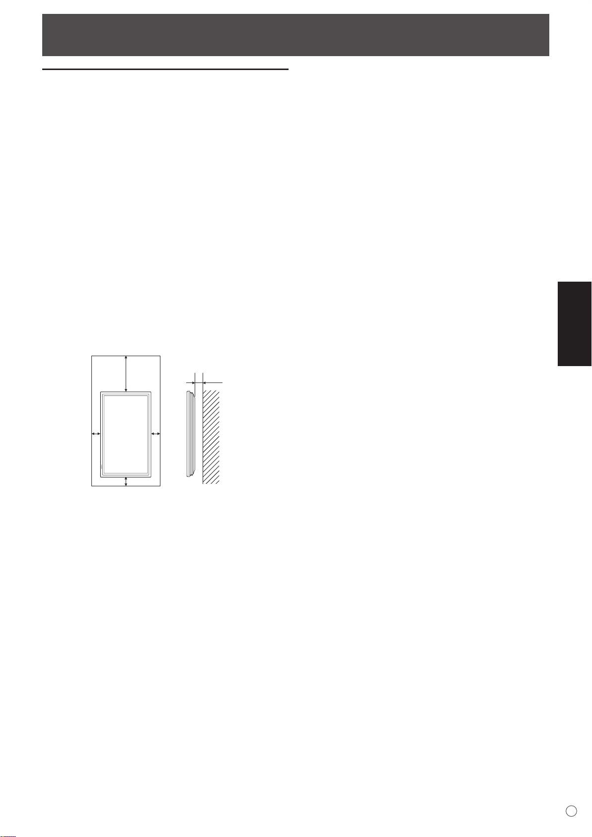
Manière d’installer le moniteur
5
4,5
30
5 5
Unité : cm
Précautions pour le montage
• Comme le moniteur est lourd, consultez votre revendeur
avant l’installation, le démontage ou le déplacement du
moniteur.
• L’installation, le démontage ou le déplacement du moniteur
doit être fait par 3 personnes ou plus.
• Lorsque vous déplacez le moniteur, assurez-vous de le
saisir par les deux poignées situées à l’arrière et sur le bas
de l’unité. Ne saisissez pas le panneau LCD. Ceci pourrait
causer une panne, un dysfonctionnement ou une blessure.
• Installez le moniteur perpendiculairement à la surface
horizontale. Si c’est nécessaire, limitez l’angle d’inclinaison
entre 0° et 20° vers le bas.
• Le montage du moniteur sur le mur demande des
compétences techniques spéciales et le travail doit être
fait par un revendeur agréé par SHARP. Vous ne devez
jamais tenter de faire ce travail vous-même. Notre société
déclinera toute responsabilité pour les accidents ou
blessures causés par un montage incorrect ou par une
mauvaise manipulation.
• Ce moniteur doit être utilisé sous une température
ambiante entre 0°C et 40°C. Laissez assez d’espace
autour du moniteur pour empêcher que la chaleur ne
s’accumule à l’intérieur.
• Ce moniteur est prévu pour être installé sur un mur ou un
pilier en béton. Un travail de renforcement pourrait
s’avérer nécessaire pour certains matériaux tels que le
plâtre, un mince panneau de plastique ou le bois avant de
commencer l’installation.
Le mur sur lequel ce moniteur et le support doivent être
installés doit pouvoir supporter, au moins, 4 fois son poids
ou d’avantage. Installez de la manière qui convient le
mieux en fonction du matériau et de la structure.
FRANÇAIS
S’il est difficile de laisser un tel espace parce que le
moniteur est installé dans une enceinte ou pour d’autres
raisons, prenez d’autres mesures, pour maintenir la
température ambiante entre 0°C et 40°C, telles que
l’installation d’un ventilateur à l’intérieur de l’enceinte.
• Ce moniteur doit être installé dans une direction verticale
seulement. Il ne peut pas être installé dans une direction
horizontale.
• Ne bloquez pas les ouvertures de ventilation. Si la
température dans le moniteur s’élève, ceci pourrait causer
un dysfonctionnement.
• Après le montage, il est recommandé de prendre des
mesures pour empêcher le moniteur de tomber. Fixez le
moniteur en attachant les crochets situés sur le dessus du
moniteur à un mur ou à un pilier avec un câble résistant et
des supports (non fournis).
• Ne placez le moniteur sur un équipement qui dégage de la
chaleur.
• A la sortie de l’usine, le moniteur est fixé au support
temporaire. Notez bien que ce support est à usage
temporaire uniquement, en attendant que le moniteur soit
correctement installé.
• Veillez à utiliser un support de table ou un support mural
conçu ou prévu pour le montage du moniteur.
F
9
Page 84

Connexion de périphériques
HV
R G
B
Borne d’entrée audio du PC
Borne d’entrée PC1
Borne d’entrée PC2
Bornes d’entrée PC3
Cr/Pr Y Cb/Pb
Borne d’entrée AV1
Bornes d’entrée AV2
Borne d’entrée AV3
Bornes d’entrée
audio de l’AV
Attention
• Veillez à bien mettre hors tension l’interrupteur principal
puis débranchez la prise de l’alimentation secteur avant de
connecter ou de déconnecter les câbles. Lisez également
le mode d’emploi de l’équipement à connecter.
• Veillez à ne pas confondre la borne d’entrée avec la borne
de sortie quand vous connectez les câbles. En confondant
les bornes d’entrée et de sortie vous pouvez causer des
dysfonctionnements et d’autres problèmes.
Connexion à un PC
• Utilisez un câble de signal (DVI-D à 24 broches) en vente
dans le commerce pour la borne d’entrée PC1. Réglez
DVI SELECT <DVI SÉLECTION> dans le menu OPTION
<OPTIONS> sur PC (DIGITAL) <PC (NUMÉRIQUE)> si
vous utilisez la borne d’entrée PC1. (Voir à la page 19.)
• Utilisez un câble de signal (Mini D-sub à 15 broches) en
vente dans le commerce pour la borne d’entrée PC2.
• Utilisez un câble de signal (BNC) en vente dans le
commerce pour les bornes d’entrée PC3. Réglez BNC
SELECT <BNC SÉLECTION> dans le menu OPTION
<OPTIONS> sur PC (ANALOG) <PC (ANALOGIQUE)> si
vous utilisez les bornes d’entrée PC3. (Voir à la page 19.)
• Utilisez un câble audio en vente dans le commerce (mini
prise stéréo) pour le borne d’entrée audio du PC. Utilisez
un câble sans résistance pour le câble audio.
Conseils
• Les images peuvent ne pas s’afficher correctement selon
l’ordinateur (carte vidéo) connecté.
• Un écran de 1 920 x 1 080 de résolution peut ne pas être
affiché correctement sur PC3 (BNC). Dans ce cas, vérifiez
les réglages de votre ordinateur (carte vidéo) pour contrôler
que les signaux d’entrée sont conformes aux spécifications
de ce moniteur. (Hsync : 66,3 kHz, Vsync : 60 Hz, et
F
Fréquence du point : 148,5 MHz). (Voir à la page 34.)
• S’il y a une case à cocher pour désactiver EDID sur le
panneau de commande d’affichage, cochez le quand vous
utilisez PC3 (BNC).
• Utilisez le réglage automatique de l’écran lorsque vous
affichez un écran de PC pour la première fois en utilisant
PC2 ou PC3, ou lorsque vous changez le réglage du PC.
(Voir à la page 22.)
• L’écran est réglé automatiquement quand SELF ADJUST
<AUTORÉGLAGE> dans le menu OPTION <OPTIONS>
est réglé sur “ON”. (Voir à la page 19.)
10
Connexion à un équipement AV
• Utilisez un câble de signal (DVD-D à 24 broches) en vente
dans le commerce pour la borne d’entrée AV1. Réglez
DVI SELECT <DVI SÉLECTION> dans le menu OPTION
<OPTIONS> sur AV (DIGITAL) <AV (NUMÉRIQUE)> si
vous utilisez la borne d’entrée AV1. (Voir à la page 19.)
• Utilisez un câble du composant (BNC) en vente dans le
commerce pour les bornes d’entrée AV2. Réglez BNC
SELECT <BNC SÉLECTION> dans le menu OPTION
<OPTIONS> sur AV (COMPONENT) <AV (COMPOSANT)>
si vous utilisez les bornes d’entrée AV2. (Voir à la page 19.)
• Utilisez un câble vidéo (BNC) en vente dans le commerce
pour la borne d’entrée AV3.
• Utilisez un câble audio (RCA) en vente dans le commerce
pour les bornes d’entrée audio de l’AV.
• La borne d’entrée AV1 est compatible avec les signaux
vidéo suivants :
1 920 x 1 080 p @ 50/59,94/60 Hz
1 920 x 1 080 i @ 50/59,94/60 Hz
1 280 x 720 p @ 50/59,94/60 Hz
720 x 576 p @ 50 Hz
720 x 480 p @ 59,94/60 Hz
640 x 480 p @ 59,94/60 Hz
• Les bornes d’entrée AV2 sont compatibles avec les signaux
vidéo suivants :
1 080i (1 125i)/50, 1 080i (1 125i)/60, 720p (750p)/50,
720p (750p)/60, 576p (625p), 576i (625i), 480p (525p),
480i (525i)
Page 85

Connexion de périphériques
(1) (2)
montre le sens de
circulation du signal.
Borne de sortie PC/AV
Bornes d’entrée PC1/AV1
Câbles de signal
numérique (DVI)
(en vente dans
le commerce)
Vers la borne de
sortie numérique
RVB du PC
Premier moniteur
Second moniteur
Bornes d’entrée PC1/AV1
Autres bornes
Bornes de sortie audio du PC/de l’AV
• Le signal audio provenant de l’équipement connecté aux
bornes d’entrée audio de l’AV ou à la borne d’entrée audio
du PC est envoyé en sortie. Connectez aux bornes
d’entrée audio de l’équipement connecté en utilisant un
câble audio (RCA) en vente dans le commerce.
• La sortie audio varie selon la sélection du mode d’entrée.
(Voir à la page 15.)
• Le niveau de l’audio peut être réglé en utilisant le réglage
de volume. (Voir à la page 15.)
• La sélection de FIXED <FIXE> de AUDIO OUTPUT
<SORTIE AUDIO> à partir du menu OPTION <OPTIONS>
fixe le volume de sortie du son provenant des bornes de
sortie audio. (Voir à la page 19.)
• Les signaux audio envoyés en sortie à partir des bornes de
sortie audio du PC/de l’AV ne peuvent pas être réglés en
utilisant le menu AUDIO.
Bornes de sortie PC/AV
Les signaux vidéo provenant de PC1 et AV1 peuvent être
envoyés en sortie vers un équipement externe compatible
HDCP. Utilisez cette borne lorsque vous connectez plusieurs
moniteurs en série par un câble DVI (en vente dans le
commerce). (Voir la description à droite.)
Les images ne peuvent pas être envoyées en sortie vers un
équipement qui n’est pas compatible HDCP.
Raccordement de plusieurs
moniteurs
Vous pouvez raccorder plusieurs moniteurs (jusqu’à 5
moniteurs) en série en utilisant les bornes d’entrée PC1/AV1
et les bornes de sortie PC/AV de ce moniteur.
Exemple de raccordement
FRANÇAIS
Bornes d’entrée/sortie RS-232C
Vous pouvez contrôler le moniteur à partir d’un PC en
raccordant un câble direct RS-232, en vente dans le
commerce, entre cette borne et le PC. (Voir à la page 24.)
Connexion des haut-parleurs
externes
Assurez vous que vous utilisez des haut-parleurs externes
avec une impédance de 6 Ω et une puissance nominale d’au
moins 7 W.
1. Tout en soulevant le couvercle, insérez l’extrémité du câble.
2. Relâchez le couvercle.
Conseils
• Assurez-vous de connecter convenablement les bornes
+ et –, et les haut-parleurs gauche et droit.
• Evitez de court-circuiter les bornes + et –.
Conseils
• La longueur du câble de signal ou la situation environnante
peut affecter la qualité de l’image.
• L’écran peut ne pas afficher une image correcte quand
on utilise des bornes autres que PC1/AV1 pour le mode
d’entrée. Dans ce cas, mettez hors tension tous les
moniteurs connectés en série puis remettez les sous
tension.
11
F
Page 86

10°
5
m
5 m
5 m
10°
Capteur de
télécommande
Raccordement du cordon d’alimentation
1
Interrupteur principal
2
Vers la prise
d’alimentation
secter
Cordon d’alimentation (fourni)
3
Borne d’entrée secteur
Attention
• N’utilisez pas un autre cordon d’alimentation que celui qui est fourni avec le moniteur.
1. Mettez hors tension l’interrupteur principal.
2. Raccordez le cordon d’alimentation (fourni) à la borne
d’entrée secteur.
3. Raccordez le cordon d’alimentation (fourni) à la prise
d’alimentation secteur.
Mise en service de la télécommande
Mise en place des piles
1. Appuyez doucement sur le capot et faites le glisser dans la
direction de la flèche.
2. Reportez-vous aux instructions dans le compartiment et
insérez les piles fournies (2 piles du format R-6) avec leur
pole positif (+) et négatif (-) orientés correctement.
3. Refermer le capot.
Conseils
• Les piles fournies (2 piles du format R-6) peuvent avoir une
durée de vie plus courte que prévue à cause des conditions
de stockage. Il est recommandé de les remplacer par des
piles neuves (en vente dans le commerce) plus tôt que
prévu.
• Si vous n’avez pas l’intention d’utiliser la télécommande
pendant une longue période, retirez les piles.
• Utilisez seulement des piles au manganèse ou alcalines.
F
12
Portée de la télécommande
La portée de la télécommande est d’environ 5 m et l’angle
de pointage doit être à environ 10° au dessus/au dessous/à
droite/à gauche du centre du capteur de télécommande.
Conseils
• N’exposez pas la télécommande au choc en la faisant
tomber ou en marchant dessus. Ceci pourrait entraîner un
dysfonctionnement.
• N’exposez pas la télécommande aux liquides, et ne la
posez pas dans un endroit avec un taux d’humidité élevé.
• La télécommande peut ne pas fonctionner correctement
si le capteur de télécommande est exposé à la lumière
directe du soleil, ou à un éclairage puissant.
• Des objets placés entre la télécommande et le capteur
de télécommande peuvent l’empêcher de fonctionner
correctement.
• Remplacez les piles lorsque leurs charges baissent, car
elles peuvent diminuer la portée de la télécommande.
• Si une lampe fluorescente est allumée près de la
télécommande, cela peut altérer son fonctionnement.
• Ne vous servez pas de la télécommande d’un autre
appareil tel qu’un conditionneur d’air ou un équipement
stéréo, etc.
Page 87

Démontage du support temporaire et des poignées
Démontage du support temporaire
Préparez les supports de suspension au mur ou un support
sur table pour monter le moniteur. Lisez le mode d’emploi des
supports au mur ou du support sur table pour la procédure
de montage correcte. (Les trous de vis pour les supports de
montage (trous M10 x 4) sont pourvus à l’arrière du moniteur.)
Attention
• Le moniteur pèse lourd. Il doit être manipulé par 3
personnes ou plus.
• A la sortie de l’usine, le moniteur est fixé au support
temporaire. Notez bien que ce support est à usage
temporaire uniquement, en attendant que le moniteur soit
correctement installé.
1. Maintenez le moniteur avec les poignées pour l’empêcher
de basculer, puis enlevez les vis (4) de fixation du support.
VisVis
Démontage des poignées
Les poignées sont détachables.
Après avoir enlevé les poignées, assurez-vous que les vis
enlevées ont été remises dans leurs trous d’origine.
FRANÇAIS
2. Soulevez le moniteur en le prenant par les poignées et par
la partie inférieure.
3. Lorsque l’installation est terminée, fixez les couvertures de
protection des trous du support, en utilisant les vis fournies.
(1) Enlevez les vis du moniteur.
(2) Fixez les couvertures de protection des trous du support
avec les vis enlevées à l’étape (1).
• Le support temporaire a été spécialement conçu pour ce
moniteur. Ne l’utilisez pas pour d’autres équipements.
13
F
Page 88

Mise sous tension et hors tension
Interrupteur principal
IN
PU
T
Diode d’alimentation
DATE/TIME SETTING
SET
CANCEL
07
/ /
OK
…
[MENU]
20
01/01/00 00
:
: :
MENU
Attention
• Mettez sous tension le moniteur d’abord avant de mettre
sous tension le PC ou l’équipement de lecture.
Mise sous tension de l’interrupteur
principal
Lorsque l’interrupteur principal est mis hors tension, le
moniteur ne peut pas être mis sous tension en utilisant le
bouton POWER (d’alimentation) sur la télécommande.
Mise sous/hors tension
Appuyez sur le bouton POWER pour la mise sous/hors
tension.
• Vous pouvez mettre sous/hors tension le moniteur en
appuyant sur l’interrupteur d’alimentation du moniteur.
• Le réglage de SCHEDULE <EMPLOI DU TEMPS> fait
clignoter la diode d’alimentation alternativement en rouge
et en orange dans le mode veille.
Réglage de la date/heure
•
Si l’heure doit être réglée lorsque le moniteur est mis
sous tension pour la première fois, l’écran de réglage de
la date/heure apparaît. Réglez la date et l’heure.
1. Appuyez sur , , ou pour sélectionner
la date et l’heure, puis appuyez sur ou pour
changer les valeurs numériques.
2. Sélectionnez SET <RÉGLER> puis appuyez sur
•
Assurez-vous que la date et l’heure sont réglées.
•
L’écran de réglage de la date/heure va disparaître
automatiquement si aucune opération n’est réalisée
pendant environ 15 secondes. La date et l’heure
peuvent être réglées en utilisant DATE/TIME SETTING
<RÉGLAGE DATE/HEURE> à partir du menu OPTION
<OPTIONS> lorsque l’écran de réglage de la date/heure
disparaît.
.
F
14
État d’une diode
d’alimentation
Allumage en vert Power sur “On”
Allumage en orange Power sur “Off” (mode Veille)
Clignotement en vert
Attention
• Lors de la mise hors tension et de la remise sous tension,
ou lorsque vous appuyez sur l’interrupteur principal ou le
bouton POWER, attendez toujours au moins 5 secondes.
Un court intervalle peut entraîner un dysfonctionnement.
Conseils
• Si le moniteur est dans le mode veille du signal
d’entrée et que vous appuyez sur le bouton POWER de la
télécommande, le moniteur entre en mode veille.
État du moniteur
Mode veille du signal d’entrée
(entrée en utilisant un PC)
Conseils
•
Réglez la date dans l’ordre “Année/Mois/Jour”.
•
Réglez l’heure sur la base de 24 heures.
•
L’horloge s’arrête après que l’état de mise hors
tension continue pendant environ 1 semaine.* L’écran
de réglage de la date/heure apparaît à la mise sous
tension. Assurez-vous que la date et l’heure sont
réglées.
(* Ceci est une indication. L’état de mise hors tension
qui arrête l’horloge dépend de l’état du moniteur.)
Neutralisation des fonctions de mise
sous/hors tension
Les fonctions de mise sous/hors tension peuvent être
neutralisées dans le but de protéger le moniteur d’une mise
hors tension accidentelle. Réglez ADJUSTMENT LOCK <OSD
VERROUILLÉ> dans le menu FUNCTION <FONCTION> sur
“2”. (Voir à la page 23.)
Page 89

Fonctionnement de base
1
2
3
4
5
6
7
8
V O L U M E 15
B R I G H T 15
INPUT MODE
SIZE
COLOR MOD
E
BRIGHT
VOLUM
E
ID No.
MODE
L
S/N
PC2 ANALOG
WIDE
ST
D
15
15
0
PN-G655RE
:
:
:
:
:
:
:
:
1 0 2 4 x 7 6 8
INFORMATION XXXX/XX/XX XXX XX:XX:X
X
V: 60 Hz H: 48.4 kH
z
4. VOL +/- (Réglage du volume)
Appuyer sur ou affiche le menu VOLUME lorsque
l’écran de menu n’est pas affiché.
Appuyez sur ou pour régler le volume du son.
* Si vous n’appuyez sur aucun bouton pendant
environ 4 secondes, le menu de VOLUME disparaît
automatiquement.
5. LUMINOSITÉ +/- (Réglage du rétroéclairage)
Appuyer sur ou affiche le menu BRIGHT <LUMIN.>
lorsque l’écran de menu n’est pas affiché.
1. ENTRÉE (sélection du mode d’entrée)
Le menu est affiché. Appuyez sur ou pour
sélectionner le mode d’entrée, puis appuyez sur pour
entrer.
* Vous pouvez sélectionner la borne d’entrée en appuyant
sur l’interrupteur d’entrée du moniteur.
Mode d’entrée Vidéo Audio
PC1 DIGITAL
<PC1 NUMÉRIQUE>
PC2 ANALOG
<PC2 ANALOGIQUE>
PC3 ANALOG
<PC3 ANALOGIQUE>
AV1 DIGITAL
<AV1 NUMÉRIQUE>
AV2 COMPONENT
<AV2 COMPOSANT>
AV3 VIDEO
<AV3 VIDÉO>
Borne d’entrée
*1
PC1
Borne d’entrée
PC2
Bornes d’entrée
*2
PC3
Borne d’entrée
*1
AV1
Bornes d’entrée
*2
AV2
Borne d’entrée
AV3
*1 Sélectionnez la borne pour DVI SELECT <DVI
SÉLECTION>. (Voir à la page 19.)
*2 Sélectionnez la borne pour BNC SELECT <BNC
SÉLECTION>. (Voir à la page 19.)
2. SOURDINE
Met hors service le volume temporairement.
Appuyez sur le bouton MUTE de nouveau pour remettre le
son au niveau précédent.
3. MENU
Affiche et met hors service l’écran de menu (voir à la page
17).
Appuyez sur ou pour régler la luminosité.
* Si vous n’appuyez sur aucun bouton pendant environ
FRANÇAIS
4 secondes, le menu de BRIGHT <LUMIN.> disparaît
automatiquement.
6. DIMENSION (Sélection de la dimension de l’écran)
Le menu est affiché.
Appuyez sur ou pour sélectionner la dimension de
l’écran. (Voir à la page 16.)
7. AFFICHAGE
Affiche l’état du moniteur. L’affichage disparaît si on appuie à
nouveau sur ce bouton, ou automatiquement après environ 15
secondes.
Borne d’entrée
audio du PC
Bornes d’entrée
audio de l’AV
8. MODE (Sélection du mode de couleur)
À chaque fois que vous appuyez sur ce bouton, le mode de
couleur change selon la séquence suivante :
STD <NORM> (Normal) → VIVID <ÉCLATANT> →
sRGB → STD <NORM> ...
• sRGB s’applique seulement à l’entrée du PC.
sRGB est la norme internationale de la représentation des
couleurs spécifiée par la IEC (International Electrotechnical
Commission (Commisson Electrotechnique Internationale)).
La conversion des couleurs est réalisée en tenant compte
des caractéristiques d’un écran à cristaux liquides et la
représentation des couleurs est trés proche de l’image
originale.
F
15
Page 90

Fonctionnement de base
Changement de format de l’image
Même quand la dimension de l’écran a changé, l’affichage peut rester le même selon le signal d’entrée.
WIDE
<LARGE>
ZOOM 1 Entrée PC Affiche l’image de format 4:3, ainsi l’écran est rempli en entier avec le même
ZOOM 2 Entrée PC Utilisez ce format si ZOOM 1 coupe les sous-titres.
Entrée PC Affiche une image qui remplit tout l’écran.
Entrée AV Une image de format 4:3 est étirée pour remplir l’écran en entier.
format d’image. Les bords de l’image peuvent être coupés.
Entrée AV
Entrée AV
NORMAL Entrée PC Affiche l’image de sorte qu’elle remplisse l’écran sans changer le format des
signaux d’entrée.
Entrée AV Affiche l’image entière de format 4:3, sans changer le format d’image.
DotbyDot
<Pt par Pt>
* :
Avec une résolution du moniteur de 1 600 x 1 200, même en sélectionnant DotbyDot <Pt par Pt>, l’écran NORMAL s’affiche.
Conseils
• L’utilisation de cette fonction de changement de format de l’image ou de celle qui affiche deux écrans, pour compresser
ou étendre l’écran pour un affichage commercial ou public dans des établissements tels que des cafés ou des hôtels peut
constituer une violation des droits des créateurs, protégés par la loi sur les droits d’auteur ; veuillez en tenir compte.
• Lorsque c’est réglé sur la fonction “Enlarge” (Agrandissement), la dimension de l’écran est fixée au mode “WIDE” <LARGE>.
• Quand l’affichage sur deux écrans est sélectionné, la dimension de l’écran ne peut pas être changée.
• L’aspect de l’image vidéo originale peut changer si vous sélectionnez une dimension d’écran avec un rapport hauteur-largeur
différent de celui de l’image originale (par exemple l’entrée de la télédiffusion ou de la vidéo provenant d’un équipement
externe).
• Lorsqu’une image de format standard (4:3) est affichée sur tout l’écran en utilisant la fonction changement de format de
l’image de ce moniteur, les bords de l’image peuvent être coupés ou déformés. Si vous voulez respecter l’intention du
créateur réglez le format d’image sur “NORMAL”.
• Lorsque reproduisez un contenu du commerce, certaines parties de l’image (telles que les sous-titres) peuvent être coupées.
Dans ce cas, sélectionnez la dimension d’écran optimale en utilisant la fonction changement de format de l’image de ce
moniteur. Avec certains logiciels, il peut se produire des bruits ou des distorsion sur les bords de l’écran. Ceci est dû aux
caractéristiques du contenu, et ne constituent pas un dysfonctionnement.
• Selon le format de l’image originale, des bandes noires peuvent rester sur les bords de l’écran.
Entrée PC Affiche les points des signaux entrés provenant du PC connecté comme points
correspondants sur l’écran. *
Entrée AV Affiche les points des signaux d’entrés comme points correspondants sur
l’écran.
F
16
Page 91

Options de menu
MENU
1 0 2 4 x 7 6 8
V: 60 Hz H: 48.4 kHz
AUTO
CLOC
K
PHASE
H-POS
V-POS
RESE
T
SCREEN
PICTURE
AUDIO
SETUP
OPTION
ENLARGE
PIP/PbyP
127
31
31
150
SCREEN PC2 ANALOG1/1
END
…
[MENU]
AUTO
CONTRAST
BLACK LEVEL
SHARPNESS
30
96
12
PC2 ANALOG1/2
PICTURE
SCREEN
PICTURE
AUDIO
SETUP
OPTION
ENLARGE
PIP/PbyP
OK…[MENU]
1 0 2 4 x 7 6 8
V: 60 Hz H: 48.4 kHz
AUTO
CONTRAST
BLACK LEVEL
SHARPNESS
40
96
12
PC2 ANALOG1/2
PICTURE
SCREEN
PICTURE
AUDIO
SETUP
OPTION
ENLARGE
PIP/PbyP
OK…[MENU]
1 0 2 4 x 7 6 8
V:
60 Hz H: 48.4 kHz
MENU
MENU
AUTO
CONTRAST
BLACK LEVEL
SHARPNESS
30
96
12
PC2 ANALOG1/2
PICTURE
SCREEN
PICTURE
AUDIO
SETUP
OPTION
ENLARGE
PIP/PbyP
OK…[MENU]
1 0 2 4 x 7 6 8
V:
60 Hz H: 48.4 kHz
4
1 3 2
Affichage de l’écran de menu
Le réglage de la vidéo et du son et les réglages des
différentes fonctions sont activés. Cette section décrit la
manière d’utiliser les options de menu. Voir les pages de 18 à
20 pour les détails de chacune des options de menu.
Exemple d’utilisation
(Réglage de CONTRAST <CONTRASTE> dans le menu
PICTURE <IMAGE>)
1. Appuyez sur
2. Appuyez sur ou pour sélectionner PICTURE
<IMAGE>, puis appuyez sur .
Le menu PICTURE <IMAGE> est affiché.
pour afficher l’écran de menu.
Conseils
• Le menu va différer en fonction du mode d’entrée.
• L’écran de menu va se fermer automatiquement si aucune
opération n’est réalisée pendant environ 15 secondes. (Les
écrans DATE/TIME SETTING <RÉGLAGE DATE/HEURE>
et SCHEDULE <EMPLOI DU TEMPS> vont s’éteindre
dans environ 4 minutes.)
Affichage de l’écran de menu
1 Nom du menu
2 Mode d’entrée
3 Une option sélectionnée (mise en évidence).
4 Résolution de l’écran du signal d’entrée, et autres données.
FRANÇAIS
3. Appuyez sur ou pour sélectionner le
CONTRAST <CONTRASTE>.
4. Appuyez sur ou pour ajuster le réglage.
Pour les options qui sont marquées , appuyez sur ,
faites les réglages puis appuyez sur
.
Conseils
• Les options qui ne peuvent pas être sélectionnées
apparaissent en gris.
(par exemple Fonction ne pouvant être supportée par le
signal d’entrée actuel)
5. Appuyez sur
menu.
deux fois pour fermer l’écran de
F
17
Page 92

MENU
MENU
MENU
MENU
Options de menu
Détails des options de menu
Le menu va différer en fonction du mode d’entrée.
SCREEN <ÉCRAN> (PC2/PC3)
AUTO
CLOCK, PHASE, H-POS, et V-POS sont réglés automatiquement.
Appuyer sur fait exécuter le réglage.
Utilisez ce réglage automatique quand vous utilisez la borne
d’entrée PC2 ou les bornes d’entrée PC3 pour afficher un
écran de PC pour la première fois ou quand vous changez le
réglage du PC. (Voir à la page 22.)
CLOCK <HEURE>
Règle la fréquence de l’horloge d’échantillonnage pour la
vidéo applicable.
Réglez lorsqu’il y a un scintillement sous forme de bandes horizontales.
Lorsque vous utilisez la mire de réglage (voir à la page 22),
faites les réglages de sorte qu’aucune bande horizontale
n’apparaisse.
PHASE
Règle la phase de l’horloge d’échantillonnage pour la vidéo
applicable.
Utile lorsque de petits caractères apparaissent avec un faible
contraste et/ou lorsqu’il y a des scintillements aux coins.
Lorsque vous utilisez la mire de réglage (voir à la page 22),
faites les réglages de sorte qu’aucune bande verticale
n’apparaisse.
* Les réglages de PHASE ne doivent être effectués
qu’après avoir réglé CLOCK correctement.
H-POS <POS H>
Règle la position horizontale de l’image.
V-POS <POS V>
Règle la position verticale de l’image.
RESET
Restaure les valeurs des options du menu SCREEN en leurs
valeurs préréglées à la sortie d’usine.
Sélectionnez “ON” et ensuite appuyez sur
.
COLOR MODE <MODE COULEUR>
Change le mode de couleur sur l’écran. Le mode de couleur
sur l’écran peut également être changé en utilisant une
télécommande. (Voir à la page 15.)
* sRGB est seulement une entrée PC. Voir à la page 15
pour les détails.
WHITE BALANCE <BALANCE COULEUR>
THRU ........................Affiche le niveau du signal d’entré tel
<SANS CHANGE> quel. (pour PC1 seulement)
PRESET ...................Sélectionne la couleur de température
<PRÉREG> en utilisant PRESET.
USER ........................
<UTIL> R-CONTRAST, G-CONTRAST, et de
PRESET <PRÉREG>
Sélectionne la couleur de température quand WHITE BALANCE
est réglée sur PRESET.
R-CONTRAST <CONTRASTE R>
Règle la composante rouge quand WHITE BALANCE est
réglée sur USER.
G-CONTRAST <CONTRASTE V>
Règle la composante verte quand WHITE BALANCE est
réglée sur USER.
B-CONTRAST <CONTRASTE B>
Règle la composante bleue quand WHITE BALANCE est
réglée sur USER.
COPY TO USER <COPIE UTILISATEUR>
Copie la valeur réglée pour PRESET vers le réglage USER.
Sélectionnez “ON” et ensuite appuyez sur
GAMMA
Sélectionnez une valeur gamma.
RESET
Restaure les valeurs des options du menu PICTURE en
leurs valeurs préréglées à la sortie d’usine.
Sélectionnez “ON” et ensuite appuyez sur
Utilisée pour le réglage de
B-CONTRAST respectivement.
.
.
PICTURE <IMAGE>
AUTO (PC2/PC3)
CONTRAST et BLACK LEVEL sont réglés automatiquement.
Appuyer sur fait exécuter le réglage.
CONTRAST <CONTRASTE>
Règle la luminosité de l’image.
BLACK LEVEL <NIVEAU NOIR>
Règle la luminosité des signaux vidéo en entier.
TINT <TEINTE> (Entrée AV)
Règle la teinte. La sélection de + change la couleur vers le
vert, et la sélection de - change la couleur vers le magenta.
COLORS <COULEUR> (Entrée AV)
Règle l’intensité de chrominance.
SHARPNESS <NETTETÉ>
Règle la définition de l’image.
ADVANCED <AVANCÉ> (Entrée AV)
Vous pouvez régler plus spécialement. (Voir à la page 22.)
F
18
AUDIO
TREBLE <AIGUS>
Règle le volume des aigus.
BASS <GRAVES>
Règle le volume des graves.
BALANCE
Règle l’équilibre des sons entre la droite et la gauche.
RESET
Restaure les valeurs des options du menu AUDIO en leurs
valeurs préréglées à la sortie d’usine.
Sélectionnez “ON” et ensuite appuyez sur
.
Page 93

STANDARD
MIRROR
<MIROIR>
ROTATE
<ROTATION>
UPSIDE DOWN
<INVERSÉ>
ABC
ABC
ABC
ABC
Options de menu
SETUP <INSTALLATION>
OSD H-POSITION <OSD POSITION H>
Règle la position horizontale de l’affichage de l’écran de menu.
OSD V-POSITION <OSD POSITION V>
Règle la position verticale de l’affichage de l’écran de menu.
LANGUAGE <LANGAGE>
Règle la langue d’affichage pour l’écran de menu.
ID No. SET <ID NO.>
Assigne des numéros d’identification aux moniteurs connectés
en série (voir à la page 25), en utilisant des câbles RS-232.
Les numéros 1 à 255 sont disponibles comme numéros
d’identification.
Si c’est réglé sur “0”, le système considère ceci comme l’état
dans lequel il n’y a aucun numéro d’identification réglé.
PICTURE FLIP <IMAGE DÉPLACÉE>
Une image retournée apparaît.
POWER ON DELAY <RETARD MARCHE>
Vous pouvez retarder l’affichage de l’écran après avoir mis
sous tension le moniteur. La période peut être réglée
jusqu’à 60 secondes par unités d’une seconde. Lorsque
cette fonction est activée, la diode d’alimentation clignote en
orange (environ à intervalle d’une seconde). Cette fonction
est désactivée lorsque 0 est spécifié
.
OPTION <OPTIONS>
DATE/TIME SETTING <RÉGLAGE DATE/HEURE>
Réglage de la date et de l’heure. Appuyez sur
pour sélectionner la date et l’heure, puis appuyez sur ou
pour changer les valeurs numériques.
Réglez la date dans l’ordre “Année/Mois/Jour”.
Réglez l’heure sur la base de 24 heures.
SCHEDULE <EMPLOI DU TEMPS> (Voir à la page 21.)
Vous pouvez régler l’heure de la mise sous et hors tension
du moniteur.
DVI SELECT <DVI SÉLECTION>
Sélectionne l’équipement qui doit être connecté à la borne
d’entrée PC1/AV1.
BNC SELECT <BNC SÉLECTION>
Sélectionne l’équipement qui doit être connecté aux bornes
d’entrée PC3/AV2.
QUICK SHOOT <RÉPONSE RAPIDE>
Réduit l’effet de traînage propre aux scènes à mouvements rapides.
COLOR SYSTEM <SYST. COULEUR>
Sélectionnez le système de couleur de l’équipement AV
qui est relié à la borne d’entrée AV3. (AUTO/PAL/PAL-60/
SECAM/NTSC3,58/NTSC4,43)
Quand AUTO est sélectionné, le système de couleur sera
automatiquement réglé en fonction du signal d’entrée.
AUDIO OUTPUT <SORTIE AUDIO>
Règle le volume de sortie du son provenant des bornes de
sortie audio du PC/de l’AV.
VARIABLE ..........
FIXED <FIXE> ....Fixe les sons.
480LINES (PC2/PC3)
Si un ordinateur connecté à la borne d’entrée PC2/PC3
a une résolution de 640 x 480 ou 848 x 480, faites une
sélection selon la résolution.
768LINES (PC2/PC3)
Si un ordinateur connecté à la borne d’entrée PC2/PC3 a
une résolution de 1 024 x 768 ou 1 280 x 768, ou 1 360 x
768, faites une sélection selon la résolution.
SELF ADJUST <AUTORÉGLAGE>
Sur un écran PC2/PC3 avec une résolution de 800 x 600,
ou plus élevée, précisez s’il faut exécuter ou non le réglage
automatique de l’écran. Si ON est sélectionné, l’écran est
automatiquement réglé quand la fréquence des signaux
d’entrée varie. “ADJUSTING” apparaît sur l’écran pendant le
réglage.
POWER MANAGEMENT <GESTION DE L’ALIMENTATION>
POWER MANAGEMENT détermine la commutation ou non
des modes, du mode sans signal au mode veille de signal d’
entrée quand l’écran du PC est affiché.
Vous pouvez régler le volume en utilisant
VOLUME.
ou
FRANÇAIS
19
F
Page 94

Options de menu
Écran
principal
Écran
annexe
Écran
principal
Écran
annexe
Écran
annexe
Écran
principal
ENLARGE <AGRANDIR> (Entrée du PC)
ENLARGE MODE <MODE LARGE>
Règle le nombre d’éléments de l’écran utilisés pour
l’agrandissement. (Voir à la page 21.)
ENLARGE POS <POS AGRANDIR>
Précise l’écran élémentaire à afficher quand la fonction
d’agrandissement est utilisée. (Voir à la page 21.)
BEZEL H / BEZEL V <MONTURE H/MONTURE V>
Règle la largeur du cadre de l’écran quand la fonction
d’agrandissement est utilisée.
H-POS <POS H>
Règlez la position horizontale de l’écran agrandi.
V-POS <POS V>
Règlez la position verticale de l’écran agrandi.
PIP/PbyP
PIP MODES <PIP MODE>
Règle la méthode d’affichage.
OFF .........Affiche un seul écran.
PIP ...........Affiche un écran annexe incrusté dans un écran
principal.
PbyP ........Affiche un écran principal et un écran annexe sur
une ligne.
PbyP2 ......Affiche un écran principal qui mesure 1 280 pixels
dans la plus longue direction et un écran annexe
sur une ligne.
PIP SIZE
Règle la dimension de l’écran annexe en mode PIP.
PIP H-POS
Règle la position horizontale de l’écran annexe en mode PIP.
PIP V-POS
Règle la position verticale de l’écran annexe en mode PIP.
PIP BLEND <PIP MÉLANGE>
En mode PIP, utilisez cette option de menu pour afficher
l’écran annexe en transparence.
PIP SOURCE
Sélectionne l’entrée du signal de l’écran annexe en mode
PIP, PbyP, PbyP2.
SOUND CHANGE <SON SOURCE>
Règle le son qui est envoyé en sortie en mode PIP, PbyP ou
PbyP2.
Si l’écran principal est affiché en plein écran par la fonction
AUTO OFF, le son pour l’écran principal est envoyé en sortie
même quand le son pour l’écran annexe est spécifié.
MAIN POS
Règle la position de l’écran principal en mode PbyP ou PbyP2.
PbyP2 POS
Règle la position de l’écran annexe en mode PbyP2.
AUTO OFF
Règle la méthode d’affi chage en l’absence de signaux pour
l’écran annexe en entrée en mode PIP, PbyP, ou PbyP2.
MANUAL .............Affiche un écran principal et un écran
<MANUEL> annexe noir.
AUTO ..................
Affiche l’écran principal en plein écran.
Conseils
• Quand WHITE BALANCE <BALANCE COULEUR> est
réglé sur THRU <SANS CHANGE>, il n’est pas possible
de régler BLACK LEVEL <NIVEAU NOIR>, CONTRAST
<CONTRASTE>, et GAMMA.
• Si COLOR MODE <MODE COULEUR> est réglée sur
sRGB ou VIVID <ÉCLATANT>, les options suivantes ne
peuvent pas être réglées.
WHITE BALANCE <BALANCE COULEUR>, PRESET
<PRÉREG>, R-/G-/B-CONTRAST <CONTRASTE R/V/B>,
COPY TO USER <COPIE UTILISATEUR>
Affichage sur deux écrans
, et GAMMA
Vous pouvez afficher les écrans du signal d’entrée du PC et
du signal d’entrée AV simultanément.
Réglez cette fonction avec “PIP MODES” <PIP MODE> dans
le menu PIP/PbyP.
PIP
Un écran annexe est affiché
dans un écran principal.
PbyP
Un écran principal et un écran
annexe sont affichés sur une
ligne.
PbyP2
Affiche un écran principal qui
mesure 1 280 pixels dans la
plus longue direction et un
écran annexe sur une ligne.
* Le signal d’entrée sélectionné actuellement est affiché sur
l’écran principal.
* Vous ne pouvez pas afficher simultanément les écrans des
signaux du même type, tels que deux types de signaux
d’entrée de PC ou deux types de signaux d’entrée AV.
Conseils
• Vous pouvez violer le droit d’auteur qui est protégé par la
loi si vous présentez les images de l’écran d’ordinateur et
de télévision/magnétoscope pour un affichage commercial
ou public.
• La dimension de l’écran pour un affichage sur deux écrans
est la même que la dimension de l’écran pour un affichage
sur un seul écran. L’écran DotbyDot <Pt par Pt> est affiché
dans le format NORMAL excepté quand il est réglé comme
écran principal PIP.
• Quand l’affichage sur deux écrans est sélectionné,
l’écran ne peut pas être agrandi.
• Quand l’affichage sur deux écrans est sélectionné, les
réglages suivants de ADVANCED <AVANCÉ> sont
invalides et le réglage est désactivé.
3D-NR, MPEG-NR, et 3D-Y/C
F
20
Page 95

Options de menu
1
3
0
2
0
1
2
4
5
6
8
9
10
3
7
11
12
13
14
15
0
1
2
5
6
7
10
11
12
3
8
13
15
16
17
18
20
21
22
23
4
914
19
24
0
1
2
3
4
5
6
7
8
4 moniteurs 9 moniteurs
16 moniteurs 25 moniteurs
Image
originale
SCHEDULE
No. POWER DAY OF THE WEEK TIME INPUT
XXXX/XX/XX XXX XX:XX:XX
PC2 ANALOG
(2)
OK
…
[MENU]
1 0 2 4 x 7 6 8
V: 60 Hz H: 48.4 kHz
(1)
(3) (4) (5)
MENU
Agrandissement
Vous pouvez disposer 4, 9, 16 ou 25 moniteurs et les intégrer
en un seul grand écran pour l’affichage.
Des vues agrandies des images séparées sont affichées sur
chaque moniteur.
SCHEDULE <EMPLOI DU TEMPS>
Vous pouvez régler l’heure de la mise sous et hors tension du
moniteur.
Réglez cette fonction avec “SCHEDULE” <EMPLOI DU
TEMPS> dans le menu OPTION <OPTIONS>. (Voir à la page
19.)
1. Appuyez sur ou pour sélectionner le chiffre de
SCHEDULE <EMPLOI DU TEMPS>, puis appuyez sur
.
2. Réglez SCHEDULE <EMPLOI DU TEMPS>. (Voir la
description ci-dessous.)
Appuyez sur ou pour sélectionner les éléments,
puis appuyez sur ou pour changer le réglage.
3. Appuyez sur
.
SCHEDULE <EMPLOI DU TEMPS> devient effectif.
FRANÇAIS
Conseils
• Les signaux d’entrée AV ne peuvent pas être utilisés dans
la fonction Enlarge (Agrandissement).
• Pour intégrer 9 moniteurs ou plus en utilisant les signaux
PC1, un séparateur de signal vidéo (en vente dans le
commerce) est nécessaire.
• Pour la connexion à PC2/PC3, un séparateur de signal
vidéo (en vente dans le commerce) est nécessaire.
(1)
● : SCHEDULE effectif
-
: SCHEDULE non effectif
(2) POWER <ALIM.>
ON : Met en fonction le moniteur à l’heure spécifiée.
OFF : Met hors fonction le moniteur à l’heure spécifiée et
met le moniteur en mode veille.
(3) DAY OF THE WEEK <JOUR DE LA SEMAINE>
Spécifie le jour de la semaine pour l’exécution de
SCHEDULE.
ONLY ONCE <UNE FOIS>
:
Exécute SCHEDULE une fois le jour spécifié.
Spécifie le jour de la semaine pour l’exécution de
SCHEDULE.
EVERY WEEK <CHAQUE SEMAINE>
:
Exécute SCHEDULE le jour de la semaine spécifié chaque
semaine. Spécifie le jour de la semaine pour l’exécution
de SCHEDULE.
Le réglage d’une période telle que “du Lundi au Vendredi”
est également possible.
EVERY DAY <CHAQUE JOUR>
:
Exécute SCHEDULE chaque jour, quel que soit le jour de
la semaine.
(4) TIME <HEURE>
Spécifie l’heure pour l’exécution de SCHEDULE.
Réglez l’heure sur la base de 24 heures.
21
F
Page 96

Options de menu
MENU
MENU
(5) INPUT <ENTRÉE>
Précise le mode d’entrée à la mise sous tension. Quand elle
n’est pas spécifiée, l’écran à la mise hors tension précédente
apparaît.
Les modes d’entrée affichés sur “PC1/AV1” dépendent des
réglages de DVI SELECT.
Les modes d’entrée affichés sur “PC3/AV2” dépendent des
réglages de BNC SELECT.
Attention
• Ne mettez pas hors tension l’interrupteur principal après le
réglage de SCHEDULE <EMPLOI DU TEMPS>.
• Précise la date et l’heure correctes. (Voir aux pages 14 et
19.)
SCHEDULE <EMPLOI DU TEMPS> ne fonctionne pas à
moins que la date et l’heure ne soient précisées.
• Vérifiez régulièrement que la date et l’heure réglées son
correctes.
Conseils
• Les options SCHEDULE <EMPLOI DU TEMPS> peuvent
être enregistrées jusqu’à 8.
• Le réglage de SCHEDULE <EMPLOI DU TEMPS> fait
clignoter la diode d’alimentation alternativement en rouge
et en orange dans le mode veille.
• Un SCHEDULE <EMPLOI DU TEMPS> qui a un chiffre
élevé a la priorité sur celui qui a un chiffre plus petit quand
les emplois du temps se chevauchent.
Options ADVANCED <AVANCÉ> (Entrée AV)
(Voir à la page 18.)
FLESH TONE <TON NATUREL>
Règle la commande des teintes.
3D-NR
Réduit le bruit des images lues sur la vidéo.
Le réglage à un niveau plus élevé réduit encore plus le bruit.
Cependant, cela peut produire une image floue.
MPEG-NR
Réduit le bruit vidéo causé par la compression numérique.
3D-Y/C (AV3)
Précise s’il faut exécuter la séparation Y/C en 3 dimensions.
Si une interférence de points ou un battement couleur se
produit dans les scènes à mouvement rapide, la sélection de
“OFF” peut améliorer la qualité de l’image.
Réglages pour l’affichage d’écran de PC
Réglage automatique
Quand vous utilisez les bornes d’entrée PC2 ou la borne
d’entrée PC3 pour afficher un écran de PC pour la première
fois, ou quand vous changez le réglage du PC, utilisez le
réglage automatique de l’écran.
1. Commutez l’entrée sur PC2 ou sur PC3 et affichez la
mire de réglage. (Voir la description ci-dessous.)
2. Appuyez sur
menu SCREEN <ÉCRAN>.
3. Appuyez sur et sélectionnez “AUTO”.
4. Appuyez sur .
Le réglage automatique est terminé en quelques secondes.
5. Appuyez sur
menu.
Conseils
• Si l’écran ne peut pas être réglé correctement avec une
opération de réglage automatique, répétez le réglage
automatique deux ou trois fois. Essayez le réglage manuel
si c’est nécessaire.
Affichage de l’écran pour le réglage
Avant de faire des réglages dans le menu SCREEN
<ÉCRAN> ou le menu PICTURE <IMAGE>, affichez une
image pour éclaircir tout l’écran. Si vous utilisez un PC sous
Windows, utilisez la mire de réglage sur le CD-ROM fourni.
Dans ce mode d’emploi, tous les termes de Windows sont en
Anglais.
Ouverture de la mire de réglage
1. Chargez le CD-ROM fourni dans le lecteur de CD-ROM
de l’ordinateur.
2. Ouvrez le CD-ROM dans [My Computer].
3. Double-cliquez sur [Adj_uty.exe].
La mire de réglage va apparaître.
Réglez l’écran automatiquement ou manuellement.
4. Lorsque le réglage est terminé, appuyez sur la touche
[Esc] sur le clavier de l’ordinateur pour quitter le
programme de réglage.
5. Ejecter le CD-ROM du lecteur de CD-ROM.
et utilisez ou pour afficher le
deux fois pour fermer l’écran de
Conseils
• Si le mode d’affichage de l’ordinateur que vous utilisez est
réglé sur 65 000 couleurs, les niveaux de couleurs dans
la mire de couleurs peuvent apparaître différemment ou
l’échelle de gris peut paraître colorée. (Ceci est dû aux
caractéristiques du signal d’entrée, et il ne s’agit pas d’un
dysfonctionnement.)
F
22
Page 97

SIZE
OFF
ON
ON
UNLOCKE
D
FUNCTION
1/1
ALL RESET
ADJUSTMENT LOCK
OSD DISPLAY
LED
RS-232C
END…[MENU]
MENU
MENU
Initialisation (Restauration)/Réglage des restrictions des fonctions
Vous pouvez restaurer les réglages en leurs valeurs
préréglées à la sortie d’usine et limiter les opérations.
1. Après avoir appuyé sur
pendant environ 5
secondes, appuyez sur , , , et sur dans
cet ordre.
2. Sélectionnez et réglez les options.
ALL RESET <TOTAL RESET>
Restaure les réglages à leurs valeurs réglées par défaut
en usine.
Appuyez sur , sélectionnez “ON” puis appuyez sur
.
Après l’initialisation, mettez l’interrupteur principal hors
tension puis remettez le sous tension.
ADJUSTMENT LOCK <OSD VERROUILLÉ>
Vous pouvez désactiver les fonctions sur le moniteur et
sur la télécommande qui utilisent les boutons.
OFF ...Active la fonction.
1 ........Désactive toutes les fonctions autres que la mise
sous/hors tension et la fonction FUNCTION.
2 ........Seule la fonction FUNCTION est activée.
Désactive toutes les fonctions autres que
FUNCTION (pas même la mise sous/hors
tension).
OSD DISPLAY <OSD>
Cache/affiche les menus.
L’écran FUNCTION ne peut pas être caché.
ON .....Affiche les menus.
OFF ...Cache les menus.
LED
Spécifie l’allumage de la diode d’alimentation.
ON .....La diode d’alimentation s’allume.
OFF ...La diode d’alimentation ne s’allume pas.
RS-232C
Spécifie si la commande via le réglage RS-232C est
autorisée (voir à la page 24).
LOCKED <VERROUILLÉ>
Désactive la commande via le réglage RS-232C.
UNLOCKED <DÉVERROUILLÉ>
Active la commande via le réglage RS-232C.
3. Appuyez sur
pour retourner à l’écran normal.
FRANÇAIS
23
F
Page 98
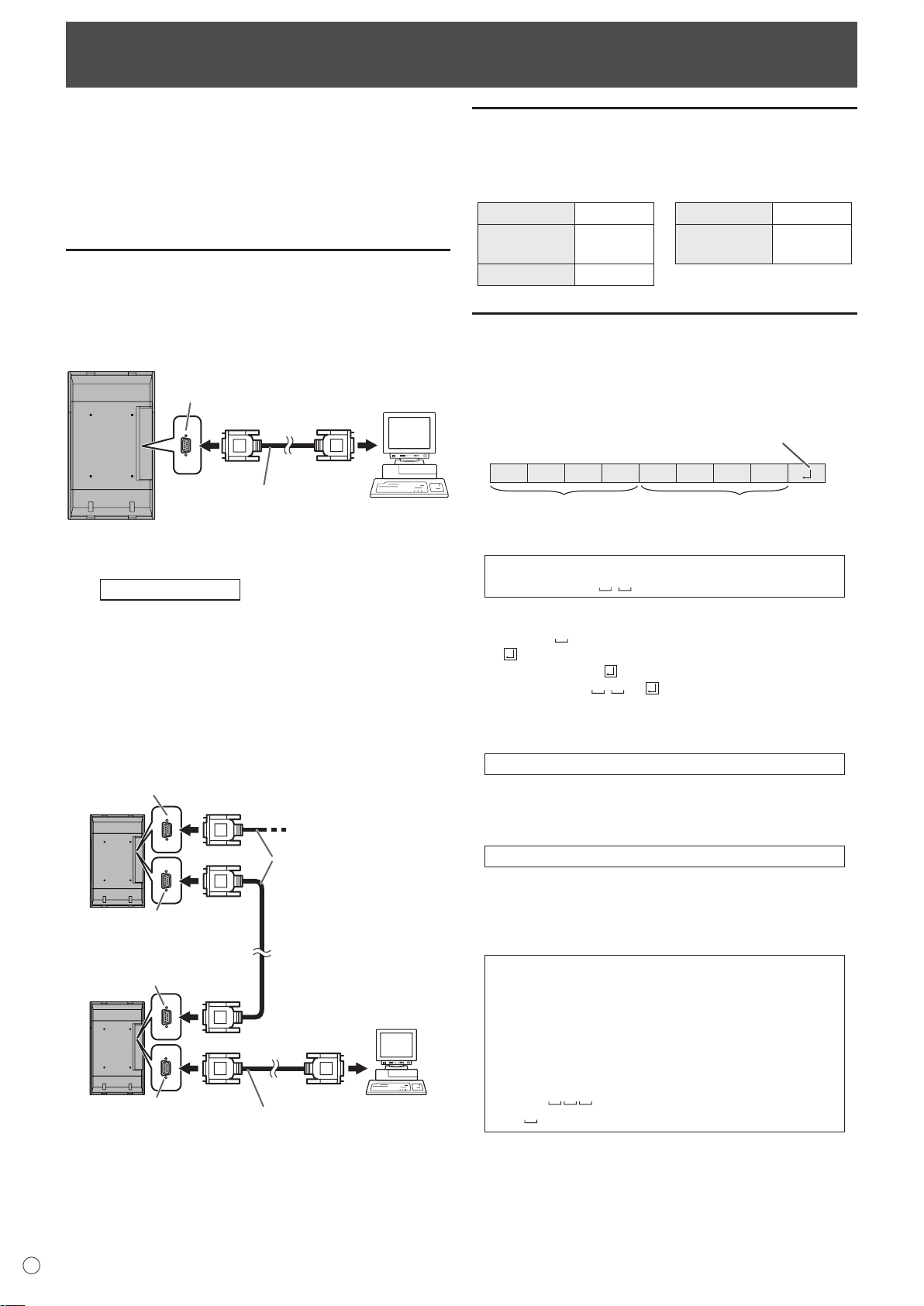
Commande du moniteur par un PC
PC
Câble direct RS-232
(en vente dans le commerce)
Ve
rs le port COM
Borne d’entrée
RS-232C
PC
Premier
moniteur
Second
moniteur
Borne de
sortie RS-232C
Borne d’entrée
RS-232C
Borne de
sortie RS-232C
Câble direct RS-232
(en vente dans le commerce)
Vers le port COM
Câbles directs RS-232
(en vente dans le commerce)
Borne d’entrée
RS-232C
C1 C2 C3 C4 P1 P2 P3 P4
Code retour
Champ commande
(4 caractères
alphanumériques prescrits)
Champ paramètre
(Série de 4 caractères
choisis parmi : 0-9, +, - espace, ?)
Vous pouvez commander ce moniteur à partir d’un PC via le
câble RS-232C (port COM) sur le PC.
Vous pouvez également raccorder plusieurs moniteurs en
série en utilisant un PC. En affectant un numéro d’identification
à chaque moniteur (voir à la page 25), vous pouvez faire la
sélection/le réglage du mode d’entrée ou vérifier le statut d’un
moniteur particulier.
Raccordement d’un PC
Raccordement d’un moniteur à un PC
Connectez le câble direct RS-232 entre le port COM du PC
(connecteur RS-232C) et la borne d’entrée RS-232C du
moniteur.
Raccordement d’une série de moniteurs
Fonctions avancées
…
Connectez le câble direct RS-232 entre le port COM du PC
(connecteur RS-232C) et la borne d’entrée RS-232C du
premier moniteur.
Puis connectez le câble direct RS-232 à la borne de sortie
RS-232C du premier moniteur et à la borne d’entrée
RS-232C du second moniteur. Connectez de la même manière
le troisième et les moniteurs suivants.
Il est possible de raccorder jusqu’a 25 moniteurs. (En fonction
de la longueur du câble utilisé et des conditions environnantes.)
Conditions de communication
Faites les réglages de communication RS-232C du PC pour
qu’ils correspondent aux réglages de communication du
moniteur comme suit :
Débit en bauds 9 600 bps
Longueur des
données
Bit de parité Aucun
8 bits
Bit d’arrêt
Commande de
flux
1 bit
Aucun
Procédure de communication
Format des commandes
Lorsqu’une commande est envoyée de l’ordinateur au
moniteur, le moniteur exécute la commande, et envoie un
message de réponse au PC.
Exemple : VOLM0030
VOLM
* Veillez à entrer 4 caractères pour le paramètre. Ajoutez des
espaces (“ ”) si c’est nécessaire.
(“ ” est un code retour (0DH, 0AH ou 0DH).)
Erreur : VOLM30
Exact : VOLM 30
Lors de la saisie d’une valeur négative en entrée, spécifiez
une valeur numérique par un nombre à trois chiffres.
Exemple : AUTR-009
30
N’utilisez pas des espaces pour MPOS, DATE, et SC01
à SC08. Spécifiez les paramètres en utilisant un nombre
spécifique de caractères.
Exemple : MPOS010097
Si dans une commande “R” apparaît dans la colonne
“Direction” du “Tableau des commandes RS-232C” de la page
28, la valeur actuelle peut être renvoyée en utilisant un “?”
comme paramètre.
Exemple :
VOLM ? ? ? ? ←
30 ←
* Si un numéro d’identification (voir à la page 25) a été
affecté (par exemple, numéro d’identification = 1).
VOLM ? ←
30 001 ←
Du PC au moniteur (Quel est le
réglage du volume actuel ?).
Du moniteur au PC (réglage du
volume actuel : 30).
Du PC au moniteur.
Du moniteur au PC.
F
24
Page 99

Commande du moniteur par un PC
O K
Code retour
(0DH, 0AH)
O K SPC 0 0 1
Numéro d’identification du moniteur qui répond
Espace (20H)
Code retour
(0DH, 0AH)
R RE
Code retour
(0DH, 0AH)
R RE SPC 0 0 1
Numéro d’identification
Espace (20H)
Code retour
(0DH, 0AH)
IW TA
Code retour
(0DH, 0AH)
EC DKOL
Code retour
(0DH, 0AH)
VOLM0020
OK
INPS0001
WAIT
OK
Intervalle de 100 ms ou plus
[Exemple]
Numéro
d’identification : 1
Numéro
d’identification : 2
Numéro
d’identification : 3
Numéro
d’identification : 4
[Exemple]
Numéro
d’identification : 3
Numéro
d’identification : 2
Numéro
d’identification : 4
Numéro
d’identification : 1
Format des codes de réponse
Lorsqu’une commande a été exécutée correctement
Une réponse est renvoyée après qu’une commande est
exécutée.
* Si un numéro d’identification a été affecté
Lorsqu’une commande n’a pas été exécutée
* Si un numéro d’identification a été affecté
Conseils
• “ERR” est renvoyée lorsqu’il n’y a pas de commande
pertinente ou lorsque la commande ne peut pas être
utilisée dans l’état actuel du moniteur.
• Si la communication n’a pas été établie pour des raisons
telles qu’une mauvaise connexion entre le PC et le
moniteur, rien n’est renvoyé (pas même le message ERR).
• Si le numéro d’identification désigné n’a été affecté à aucun
moniteur (par exemple, si la commande IDSL0002 a été
utilisée, mais qu’aucun moniteur avec l’identité égale à 2
n’a été trouvé), aucune réponse n’est renvoyée.
Intervalle de communication
• Après le renvoi de OK ou ERR, vous devez envoyer les
commandes suivantes.
Pour régler l’expiration du délai, spécifiez 10 secondes ou
un temps plus long.
• Fournit un intervalle de 100 ms ou plus entre la réponse
à une commande et la transmission de la commande
suivante.
Fonctions avancées
Cette section explique comment commander des moniteurs
raccordés en série. La procédure de communication de base
est la même que celle décrite dans la section “Raccordement
d’un moniteur à un PC”.
Numéros d’identification
Vous pouvez affecter un numéro d’identification unique à
chaque moniteur (voir à la page 19). Ceci vous permettra
d’envoyer des commandes à un moniteur particulier d’un
ensemble de moniteurs raccordés en série.
Vous pouvez affecter des numéros d’identification à partir des
écrans de menu (en utilisant la télécommande) ou à partir du
PC en utilisant le câble RS-232.
FRANÇAIS
Si l’exécution de la commande prend du temps
Quand les commandes suivantes sont utilisées, la réponse
“WAIT” est renvoyée. Dans ce cas, une valeur va être
renvoyée si vous attendez un instant. N’envoyez pas de
commande durant cette période.
Aucun numéro d’identification n’est indiqué dans la réponse
WAIT.
• Les commandes qui renvoient WAIT :
1. Quand la fonction de répétition est utilisée
2. Quand une commande IDSL ou IDLK est utilisée
3. Quand l’une des commandes suivantes est utilisée :
RSET, INPS, ASNC, WIDE, EMAG, EPOS, PXSL,
POWR, AGIN, MWIN, MWIP, MWPP, ESTG
Quand la commande par liaison RS232C a été verrouillée
(pour empêcher son emploi) en utilisant la fonction
verrouillage des commandes (voir à la page 23)
Si les moniteurs sont raccordés comme on le voit
ci-dessus, vous pouvez faire exécuter des commandes
comme “Réglez le volume sonore du moniteur numéro 4 à
20”.
Lorsque vous commandez aux moniteurs raccordés en série
en les désignant par leur numéro d’identification, vous devez
éviter toute duplication de numéro d’identification.
Les numéros d’identification n’ont pas besoin d’être affectés
dans un ordre ascendant à partir du PC. Les moniteurs
peuvent également être raccordés comme on le voit
ci-dessous.
25
F
Page 100

Commande du moniteur par un PC
Numéro
d’identification : 1
Numéro
d’identification : 2
Numéro
d’identification : 3
Numéro
d’identification : 4
[Exemple]
Numéro
d’identification : 1
Numéro
d’identification : 2
Numéro
d’identification : 3
Numéro
d’identification : 4
Commandes liées aux numéros d’identification
Les exemples de commandes montrés sur cette page
supposent la configuration de raccordement et les numéros
d’identification suivants.
IDST ......... Un moniteur recevant cette commande s’attribue
son numéro d’identification dans le champ
paramètre.
Exemple :
IDST0001
OK 001 ←
Conseils
Le numéro d’identification du moniteur
est réglé à 1.
Vous pouvez leur affecter automatiquement des numéros
d’identification en utilisant la commande IDST avec la Fonction
de répétition (voir la “Fonction de répétition” à la page 27).
Par exemple, l’utilisation de la commande “IDST001+”, affecte
automatiquement les numéros d’identification comme on le
voit ci-dessous.
Commande d’affectation de numéro
IDST001 +
←
d’identification avec la fonction de répétition
WAIT
OK 001 ←
OK 002 ←
OK 003 ←
OK 004 ←
Réponse “OK” du numéro d’identification : 1
Réponse “OK” du numéro d’identification : 2
Réponse “OK” du numéro d’identification : 3
Réponse “OK” du numéro d’identification : 4 (Fin)
IDSL ........Le paramètre de cette commande désigne le
numéro d’identification du moniteur. Ce moniteur
sera sujet à la prochaine commande.
Exemple :
IDSL0002 ←
WAIT ←
OK 002 ←
VOLM0030 ←
WAIT ←
OK 002 ←
VOLM0020 ←
OK 001 ←
La commande suivante est pour le moniteur
dont le numéro d’identification est égal à 2.
Recherche du moniteur dont le numéro
d’identification est égal à 2.
Trouvé le moniteur dont le numéro
d’identification est égal à 2.
Règle le volume sonore du moniteur dont
le numéro d’identification est égal à 2 à 30.
Traitement en cours.
Réponse OK du moniteur dont le numéro
d’identification est égal à 2.
Règle le volume sonore à 20.
Le volume sonore du moniteur dont le
numéro d’identification est égal à 1 (celui
qui est raccordé directement au PC) est
réglé à 20.*
* La commande IDSL est effective une fois seulement,
pour la commande qui la suit immédiatement.
IDLK ........
Le paramètre de cette commande désigne le
numéro d’identification du moniteur. Ce moniteur
sera sujet à toutes les commandes qui suivront.
Exemple :
Les commandes suivantes sont
IDLK0002 ←
WAIT ←
OK 002 ←
VOLM0030 ←
WAIT ←
destinées au moniteur dont le numéro
d’identification est égal à 2.
Recherche du moniteur dont le numéro
d’identification est égal à 2.
Trouvé le moniteur dont le numéro
d’identification est égal à 2.
Règle le volume sonore du moniteur
dont le numéro d’identification est égal
à 2 à 30. *
Traitement en cours.
OK 002
Règle le volume sonore du moniteur
VOLM0020 ←
dont le numéro d’identification est égal
à 2 à 20.*
WAIT
OK 002
IDLK0000 ←
WAIT ←
OK 002 ←
Annulation de la sélection du numéro
d’identification fixé.
Annulation de la commande IDLK.
Annulation effective.
VOLM0010
Le volume sonore du moniteur dont le
numéro d’identification est égal à 1 (celui
OK 001 ←
qui est raccordé directement au PC)
est réglé à 10. (La commande IDLK est
annulée.)
* La commande IDLK reste effective jusqu’à ce
qu’elle soit annulée, ou que le moniteur soit mis
hors fonction.
IDCK ........Affiche le numéro d’identification actuellement
affecté à un moniteur, et fournit le numéro
d’identification actuellement sélectionné pour une
commande IDLK (si elle a été utilisée).
Exemple :
(Après l’exécution de la commande IDLK0002)
IDCK0000
ID : 001 IDLK : 002
IDCK000 +
WAIT
ID : 001 IDLK : 000
ID : 002 IDLK : 000
ID : 003 IDLK : 000
ID : 004 IDLK : 000
(Le paramètre n’a aucune
←
signification.)
Réponse renvoyée. Le numéro
d’identification est également
←
affiché sur l’écran du moniteur.
←
Fonction de répétition (Si une
commande est envoyée en
utilisant la fonction de répétition,
la sélection de numéro
d’identification en utilisant les
commandes IDSL ou IDLK est
annulée.).
F
26
 Loading...