

Page 1
PG-M25X
SERVICE MANUAL
SERVICE-ANLEITUNG
S62L4PG-M25X/
DIGITAL MULTIMEDIA PROJECTOR
DIGITALER MULTIMEDIA PROJEKTOR
PG-M25X
MODEL
MODELLE
In the interests of user-safety (Required by safety regulations in some countries) the set should be restored
to its original condition and only parts identical to those specified should be used.
AN-60KT
Im lnteresse der Benutzersicherheit (erforderliche Sicherheitsregeln in einigen Ländern) muß das Gerät in seinen
Originalzustand gebracht werden. Außerdem dürfen für die spezifizierten Bauteile nur identische Teile verwendet
werden.
CONTENTS
Page
» SPECIFICATIONS ............................................. 2
» IMPORTANT SERVICE SAFETY
NOTES (for USA)............................................... 3
» NOTE TO SERVICE PERSONNEL ................... 4
» OPERATION MANUAL ...................................... 8
» REMOVING OF MAJOR PARTS ..................... 13
» RESETTING THE TO TAL LAMP TIMER ......... 19
» ELECTRICAL ADJUSTMENT........................... 21
» TROUBLE SHOOTING TABLE ........................ 29
» CHASSIS LAYOUT .......................................... 96
» BLOCK DIAGRAM........................................... 98
» OVERALL WIRING DIAGRAM ...................... 100
» SCHEMATIC DIAGRAM ................................ 104
» PRINTED WIRING BOARD ASSEMBLIES ... 152
» PARTS LIST
Ë
ELECTRICAL PARTS ................................ 159
Ë
CABINET AND MECHANICAL PARTS ..... 174
Ë
ACCESSORIES PARTS ............................ 178
Ë
PACKING PARTS....................................... 178
» PACKING OF THE SET ................................. 179
» AN-60KT ........................................................ 180
» TECHNISCHE DATEN..................................... 50
» HINWEISE FÜR DAS
WARTUNGSPERSONAL ................................ 51
» BEDIENUNGSANLEITUNG ............................ 53
» AUSBA U WICHTIGER TEILE.......................... 58
» RÜCKSTELLEN DES
LAMPENBETRIEBSZEIT-TIMERS .................. 64
» ELEKTRISCH EINSTELLUNG ........................ 67
» FEHLERSUCHTABELLE ................................. 75
» CHASSIS-ANORDNUNG ................................ 96
» BLOCKSCHALTBILD ....................................... 98
» GESAMTSCHALTPLAN ................................ 100
» SCHEMATISCHER SCHALTPLAN................ 104
» LEITERPLATTENEINHEITEN ....................... 152
» ERSATZTEILLISTE
Ë
ELEKTRISCHE BAUTEILE ....................... 159
Ë
GEHÄUSE UND MECHANISCHE
BAUTEILE.................................................. 174
Ë
ZUBEHÖRTEILE ....................................... 178
Ë
VERPACKUNGSTEILE.............................. 178
» VERPACKEN DES GERÄTS......................... 179
» AN-60KT ........................................................ 180
INHALT
Seite
SHARP CORPORATION
This document has been published to be used for
after sales service only.
The contents are subject to change without notice.
Page 2

PG-M25X
Specifications
Product type
Video system
Display method
DMD panel
Projection lamp
Component input signal
(INPUT1)
Horizontal resolution
Computer RGB input signal
(INPUT 1)
S-video input signal
(INPUT 2)
Video input signal
(INPUT 3)
Pixel clock
Vertical frequency
Horizontal frequency
Audio input signal
PC card slot
Audio output
Speaker system
Rated voltage
Input current
Rated frequency
Power consumption
Heat dissipation
Operating temperature
Storage temperature
Cabinet
GyroRemote Radio Frequency Range
Dimensions (approx.)
Weight (approx.)
Supplied accessories
Replacement parts
Digital Multimedia Projector
Model
PG-M25X
NTSC 3.58/NTSC 4.43/PAL/PAL-M/PAL-N/PAL 60/SECAM/
DTV480I/DTV480P/DTV720P/DTV1080I
Single Chip Digital Micromirror Device™ (DMD™) by Texas Instruments
Panel size: 0.7" (17.8 mm), 1 chip XGA DMD
No. of dots: 786,432 dots (1,024 [H] × 768 [V])
Lens
1–1.2 × zoom lens, F1.75–2.04, f = 28.0–33.5 mm
High Intensity Discharge Lamp (HID Lamp), DC 210 W
29-pin connector
DVI input signal:Digital 250–1,000 mV 50 Ω
Y: 1.0 Vp-p, sync negative, 75 Ω terminated
P
: 0.7 Vp-p, 75 Ω terminated
B
: 0.7 Vp-p, 75 Ω terminated
P
R
700 TV lines (DTV720P)
29-pin connector
RGB separate/sync on green type analog input: 0–0.7 Vp-p, positive, 75 Ω terminated
HORIZONTAL SYNC. SIGNAL: TTL level (positive/negative)
VERTICAL SYNC. SIGNAL: Same as above
4-pin Mini DIN connector
Y (luminance signal): 1.0 Vp-p, sync negative, 75 Ω terminated
C (chrominance signal): Burst 0.286 Vp-p, 75 Ω terminated
RCA connector: VIDEO, composite video, 1.0 Vp-p, sync negative, 75 Ω
terminated
12–230 MHz
43–200 Hz*
15–126 kHz
ø3.5 mm M
PCMCIA-TYPE II
2.0 W (monaural)
4 cm × 3 cm
AC 100–240 V
3.2 A
50/60 Hz
295 W
XXXX BTU/hour
41°F to 95°F (+5°C to +35°C)
–4°F to 140°F (–20°C to +60°C)
Plastic
49.825 – 49.895 MHz (for U.S., Canada etc.), 40.667 – 40.695 MHz (for Europe, Oceania,
Asia)
85⁄8" × 3" × 11 15⁄16" (219 (W) × 76 (H) × 303 (D) mm) (main body only)
3
⁄4" × 3 1⁄4" × 12 1⁄2" (223 (W) × 83 (H) × 318 (D) mm) (including adjustment feet
8
and projecting parts)
5.8 lbs. (2.6 kg)
GyroRemote for U.S., Canada etc., GyroRemote for Europe, Australia, Oceania and Asia, Four
R-03 batteries, Power cord for U .S ., Canada etc. (6', 1.8 m), Power cord for Europe, e xcept U .K.
(6', 1.8 m), Power cord for U.K., Hong Kong and Singapore (6', 1.8 m), Power cord for Australia,
New Zealand and Oceania (6', 1.8 m), D VI to 15-pin D-sub cable (6', 1.8 m), USB cable (6', 1.8 m),
Carrying case, Lens cap (attached), Lens cap strap, Terminal cover (attached), CD-ROM, Operation manual, Quick reference guides, Wireless Reality operation manual, Wireless LAN PC
Card IMPORTANT INFORMATION.
Lamp unit (Lamp/cage module) (BQC-PGM20X//1), GyroRemote for U.S., Canada etc.
(RRMCG1631CESA), GyroRemote for Europe, Australia, Oceania and Asia (RRMCG1653CESA),
Four R-03 batteries (“AAA” size, UM/SUM-4, HP-16, or similar), Po wer cord f or U.S ., Canada etc.
(QACCDA007WJPZ), Power cord for Europe, except U.K. (QACCV4002CEZZ), Power cord for
U.K., Hong Kong and Singapore (QACCB5024CENA), Power cord for Australia, New Zealand
and Oceania (QACCL3022CEZZ), DVI to 15-pin D-sub cable (QCNWGA010WJZZ), USB cable
(QCNWG0001WJPZ), T wo wireless LAN cards (AN-WC11B), Carrying case (GCASN0005CESA),
Lens cap (CCAPHA001WJ01), Lens cap strap (UBNDT0013CEZZ), Terminal cover
(GCOVD0103CESA), CD-ROM (UDSKA0058CEN1), Operation manual (TINS-A046WJZZ),
Quick reference guides, Wireless LAN PC Card IMPORTANT INFORMATION.
Analog 0.7 Vp-p 75 Ω
INIJACK: AUDIO, 0.5 Vrms, more than 47 kΩ (stereo)
* Temporary noise may be visible with vertical frequencies above 100Hz if OSD functions are activated.
This SHARP projector uses a DMD panel. This very sophisticated panel contains 786,432 pixels. As with any high
technology electronic equipment such as large screen TVs,
video systems and video cameras, there are certain acceptable tolerances that the equipment must conform to.
Specifications are subject to change without notice.
This unit has some inactive pixels within acceptable tolerances which may result in inactive dots on the picture screen.
This will not affect the picture quality or the life expectancy
of the unit.
2
Page 3

PG-M25X
2
2
IMPORTANT SERVICE SAFETY NOTES (for USA)
Ë Service work should be performed only by qualified service technicians who are
thoroughly familiar with all safety checks and servicing guidelines as follows:
WARNING
1. For continued safety, no modification of any circuit
should be attempted.
2. Disconnect AC power before servicing.
BEFORE RETURNING THE PROJECTOR:
(Fire & Shock Hazard)
Before returning the projector to the user, perform
the following safety checks:
1. Inspect lead wires are not pinched between the
chassis and other metal parts of the projector.
2. Inspect all protective devices such as non-metallic
control knobs, insulating materials, cabinet backs,
adjustment and compartment covers or shields,
isolation resistor-capacity networks, mechanical
insulators, etc.
3. To be sure that no shock hazard exists, check for
current leakage in the following manner:
» Plug the AC cord directly into a 120-volt AC outlet,
(Do not use an isolation transformer for this test).
» Using two clip leads, connect a 1.5k ohm, 10 watt
resistor paralleled by a 0.15µF capacitor in parallel
between all exposed metal cabinet parts and earth
ground.
» Use an AC voltmeter with sensitivity of 5000 ohm
per volt., or higher, sensitivity to measure the AC
voltage drop across the resistor (See Diagram).
» All checks must be repeated with the AC plug
connection reversed. (If necessary, a non-polarized
adapter plug must be used only for the purpose of
completing these checks.)
Any reading of 0.3 volts RMS (this corresponds to
0.2 milliamp. A C .) or more is e xcessiv e and indicates
a potential shock hazard which must be corrected
before returning the unit to the owner.
AC
VOLTMETER
1.5k ohm (10W)
0.15µF
TEST PROBE
TO EXPOSED
METAL PARTS
CONNECT TO KNOWN
EARTH GROUND
234567890123456789012345678901212345678901234567890123456789012123456789012345678901234567890121
SAFETY NOTICE
Many electrical and mechanical parts in Projector have
special safety-related characteristics.
These characteristics are often not evident from visual
inspection, nor can protection afforded by them be
necessarily increased by using replacement
components rated for higher voltage, wattage, etc.
Replacement parts which have these special safety
characteristics are identified in this manual; electrical
components having such features are identified by “å”
and shaded areas in the Replacement Parts Lists and
Schematic Diagrams. For continued protection,
replacement parts must be identical to those used in
the original circuit. The use of a substitute replacement
parts which do not have the same safety characteristics
as the factory recommended replacement parts shown
in this service manual, may create shock, fire or other
hazards.
AVIS POUR LA SECURITE
De nombreuses pièces, électriques et mécaniques, dans
les projecteur à présentent des caractéristiques
spéciales relatives à la sécurité, qui ne sont souvent
pas évidentes à vue.
Le degré de protection ne peut pas être nécessairement
augmentée en utilisant des pièces de remplacement
étalonnées pour haute tension, puissance, etc.
Les pièces de remplacement qui présentent ces
caractéristiques sont identifiées dans ce manuel;
les pièces électriques qui présentent ces particularités
sont identifiées par la marque “å” et hachurées dans
la liste des pièces de remplacement et les diagrammes
schématiques. Pour assurer la protection, ces pièces
doivent être identiques à celles utilisées dans le circuit
d’origine. L’utilisation de pièces qui n’ont pas les mêmes
caractéristiques que les pièces recommandées par
l’usine, indiquées dans ce manuel, peut provoquer des
électrocutions, incendies ou autres accidents.
WARNING: The bimetallic component has the primary
conductive side exposed. Be very careful in
handling this component when the power is on.
234567890123456789012345678901212345678901234567890123456789012123456789012345678901234567890121
AVERTISSEMENT:La composante bimétallique dispose du
conducteur primaire dénudé. Faire
attention lors de la manipulation de cette
composante sous tension.
3
Page 4
PG-M25X
NOTE TO SERVICE
PERSONNEL
UV-RADIATION PRECAUTION
The light source, metal halide lamp, in the pr ojector
emits small amounts of UV-Radiation.
AVOID DIRECT EYE AND SKIN EXPOSURE.
To ensure safety please adhere to the following:
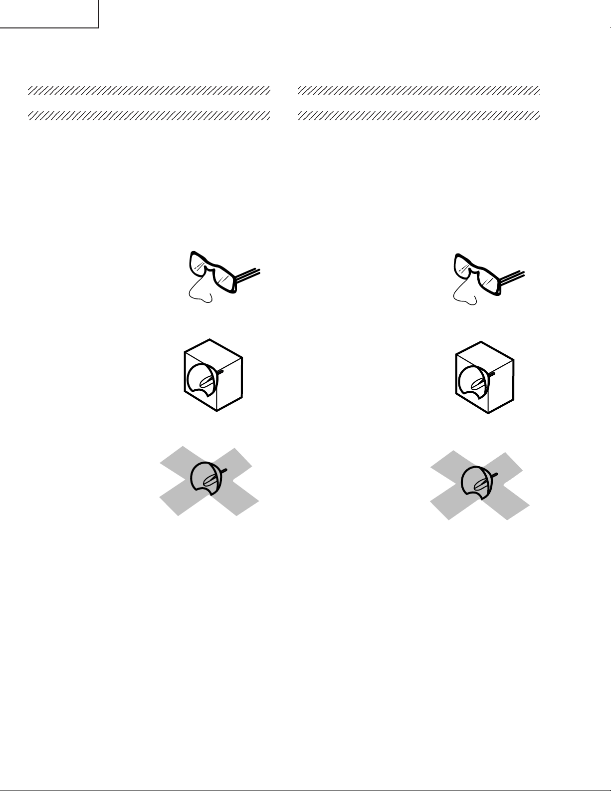
1. Be sure to wear sun-glasses when servicing the
projector with the lamp
turned “on” and the top
enclosure removed.
2. Do not operate the lamp outside of the lamp housing.
NO TE POUR LE PERSONNEL
D’ENTRETIEN
PRECAUTION POUR LES RADIATIONS UV
La source de lumière, la lampe métal halide,
dans le projecteur émet de petites quantités de
radiation UV.
EVITEZ TOUTE EXPOSITION DIRECTE
DES YEUX ET DE LA PEAU.
Pour v otre sécurité, nous vous prions de respecter
les points suivants:
1. Toujours por ter des lunettes de soleil lors d’un
entretien du projecteur
avec la lampe allumée
et le haut du coffret retiré.
2. Ne pas faire fonctionner la lampe à l’extér ieur du
boîtier de lampe.
3. Do not operate for more than 2 hours with the
enclosure removed.
UV-Radiation and Medium Pressure
Lamp Precautions
1. Be sure to disconnect the AC plug when replacing
the lamp.
2. Allow one hour for the unit to cool down before
servicing.
3. Replace only with same type lamp. Type BQCPGM20X//1 rated 85V/210W.
4. The lamp emits small amounts of UV-Radiation,
avoid direct-eye contact.
5. The medium pressure lamp involves a risk of
explosion. Be sure to follow installation instructions
described below and handle the lamp with care.
3. Ne pas faire fonctionner plus de 2 heures avec le
coffret retiré.
Précautions pour les radiations UV
et la lampe moyenne pression
1. Toujours débrancher la fiche AC lors du
remplacement de la lampe.
2. Laisser l’unité refroidir pendant une heure avant de
procéder à l’entretien.
3. Ne remplacer qu’avec une lampe du même type.
Type BQC-PGM20X//1 caractéristique 85V/210W.
4. La lampe émet de petites quantités de radiation UVéviter tout contact direct avec les yeux.
5. La lampe moyenne pression implique un risque
d’explosion. Toujours suivre les instructions
d’installation décrites ci-dessous et manipuler la
lampe avec soin.
4
Page 5
PG-M25X
4
5
UV-RADIATION PRECAUTION (Continued)
23456789012345678901234567890121234567890123
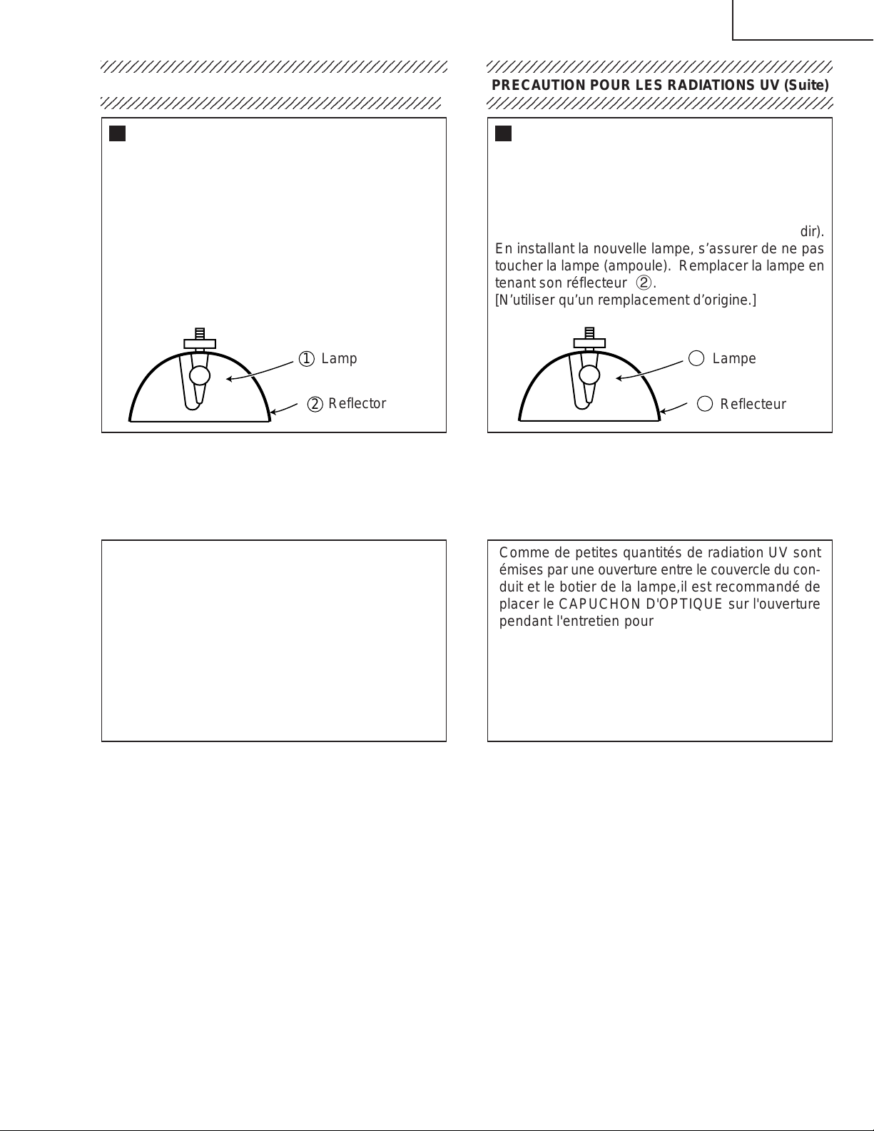
Lamp Replacement
Note:
Since the lamp reaches a very high temperature
during units operation replacement of the lamp
should be done at least one hour after the power
has been turned off. (to allow the lamp to cool off.)
Installing the new lamp, make sure not to touch the
lamp (bulb) replace the lamp by holding its reflector
2.
[Use original replacement only.]
Lamp
1
Reflector
2
DANGER ! –– Ne ver turn the power on without the
lamp to avoid electric-shock or damage of the
devices since the stabilizer generates high v oltages
at its start.
PRECAUTION POUR LES RADIATIONS UV (Suite)
234567890123456789012345678901212345678901234
Remplacement de la lampe
Remarque:
Comme la lampe devient très chaude pendant le
fonctionnement de l’unité, son remplacement ne doit
être effectué au moins une heure après avoir coupé
l’alimentation (pour permettre à la lampe de refroidir).
En installant la nouvelle lampe, s’assurer de ne pas
toucher la lampe (ampoule). Remplacer la lampe en
tenant son réflecteur 2.
[N’utiliser qu’un remplacement d’origine.]
1
Lampe
2
Reflecteur
DANGER ! –– Ne jamais mettre sous tension sans
la lampe pour éviter un choc électrique ou des
dommages des appareils car le stabilisateur génère
de hautes tensions à sa mise en route.
Since small amounts of UV-Radiation are emitted
from an opening between the duct cover and the
lamp housing, it is recommended to place the LENS
CAP on the opening during servicing to avoid eye
and skin exposure.
Note: Please obtain a lens cap before servicing a
models PG-M25X that is received without
one.
Comme de petites quantités de radiation UV sont
émises par une ouverture entre le couvercle du conduit et le botier de la lampe,il est recommandé de
placer le CAPUCHON D'OPTIQUE sur l'ouverture
pendant l'entretien pour éviter une exposition des
yeux et la peau.
Remarque: Priére de se procurer un capuchon
d'optique acant d'entretien un modéle
PG-M25X qui est livré sans.
5
Page 6
PG-M25X
WARNING: High brightness light source, do not stare into the beam of light, or view directl y . Be especially
careful that children do not stare directly in to the beam of light.
WARNING: TO REDUCE THE RISK OF FIRE OR ELECTRIC SHOCK, DO NOT EXPOSE THIS UNIT TO
MOISTURE OR WET LOCATIONS.
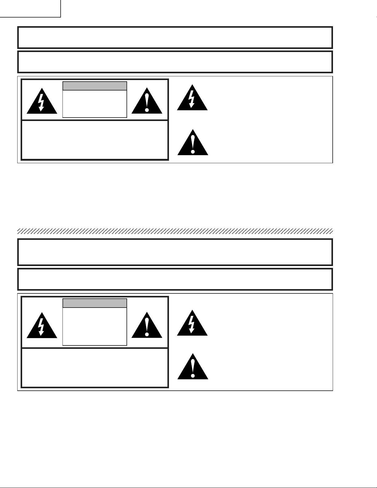
CAUTION
RISK OF ELECTRIC SHOCK.
DO NOT REMO VE SCREWS
EXCEPT SPECIFIED USER
SERVICE SCREWS
CAUTION: TO REDUCE THE RISK OF ELECTRIC SHOCK,
DO NOT REMO VE CABINET.
NO USER-SERVICEABLE PARTS EXCEPT LAMP UNIT.
REFER SERVICING T O QU ALIFIED SERVICE
PERSONNEL.
The lighting flash with arrowhead within
a triangle is intended to tell the user that
parts inside the product are risk of electric
shock to persons.
The exclamation point within a triangle is
intended to tell the user that important
operating and servicing instructions are
in the manual with the projector.
AVERTISSEMENT: Sour ce lumineuse de grande intensité. Ne pas fixer le faisceau lumineux ou le regar der
directement. Veiller particulièrement à éviter que les enfants ne fixent directement le
faisceau lumineux.
A VERTISSEMENT : AFIN D’EVITER T OUT RISQ UE D’INCENDIE OU D’ELECTR OCUTION, NE PAS PLACER
CET APPAREIL DANS UN ENDROIT HUMIDE OU MOUILLE.
ATTENTION
RISQUE
D’ELECTR OCUTION NE
PASRETIRER LES VIS, A
L’EXCEPTION DES VIS DE
REPARATION UTILISATEUR
SPECIFIEES
ATTENTION: POUR EVITER TOUT RISQ UE
D’ELECTR OCUTION, NE PAS RETIRER LE CAPOT.
AUCUNE DES PIECES INTERIEURES N’EST REPARABLE
PAR L ’UTILISATEUR, A L’EXCEPTION DE L’UNITE DE
LAMPE. POUR T OUTE REPARATION, S’ADRESSER A UN
TECHNICIEN D’ENTRETIEN QUALIFIE.
L’éclair terminé d’une flèche à l’intérieur
d’un triangle indique à l’utilisateur que les
pi‘eces se trouvant dans l’appareil sont
susceptibles de provoquer une décharge
électrique.
Le point d’exclamation à l’intérieur d’un
triangle indique à l’utilisateur que les
instructions de fonctionnement et
d’entretien sont détaillées dans les
documents fournis avec le projecteur.
6
Page 7
PG-M25X
Precautions for using lead-free solder
1 Employing lead-free solder
"Input, Key, Gyro and Gyro-Sub PWBS" of this model employs lead-free solder. The LF symbol indicates lead-free
solder, and is attached on the PWBs and service manuals. The alphabetical character following LF shows the type
of lead-free solder.
Example:
L Fa
Indicates lead-free solder of tin, silver and copper.
2 Using lead-free wire solder
When fixing the PWB soldered with the lead-free solder, apply lead-free wire solder. Repairing with conventional
lead wire solder may cause damage or accident due to cracks.
As the melting point of lead-free solder (Sn-Ag-Cu) is higher than the lead wire solder by 40°C, we recommend you
to use a dedicated soldering bit, if you are not familiar with how to obtain lead-free wire solder or soldening bit,
contact our service station or service ranch in your area.
3 Soldering
As the melting point of lead-free solder (Sn-Ag-Cu) is about 220°C which is higher than the conventional lead solder
by 40°C, and as it has poor solder wettabillty, you may be apt to keep the soldering bit in contact with the PWB for
extended period of time. However, Since the land ma y be peeled off or the maxim um heat-resistance temperature of
parts may be excoeded, remove the bit from the PWB as soon as you conurm the steady soldering condition.
Lead-free solder contains more tin, and the end of the soldering bit may be easily corroded. Make sure to tum on and
off the power of the bit as required.
if a different type of solder stays on the tip of the soldering bit, it is alloyed with lead-free solder. Clean the bit after
every use of it.
When the tip of the soldering bit is blackened during use, file it with steel wool or fine sandpaper.
Becareful when replacing parts with polarity indication on the PWB silk.
Lead-free wire solder for servicing
Part No. ★ Description Code
ZHNDAi123250E J φ0.3mm 250g(1roll) BL
ZHNDAi126500E J φ0.6mm 500g(1roll) BK
ZHNDAi12801KE J φ1.0mm 1kg(1roll) BM
7
Page 8
PG-M25X
Location of Controls
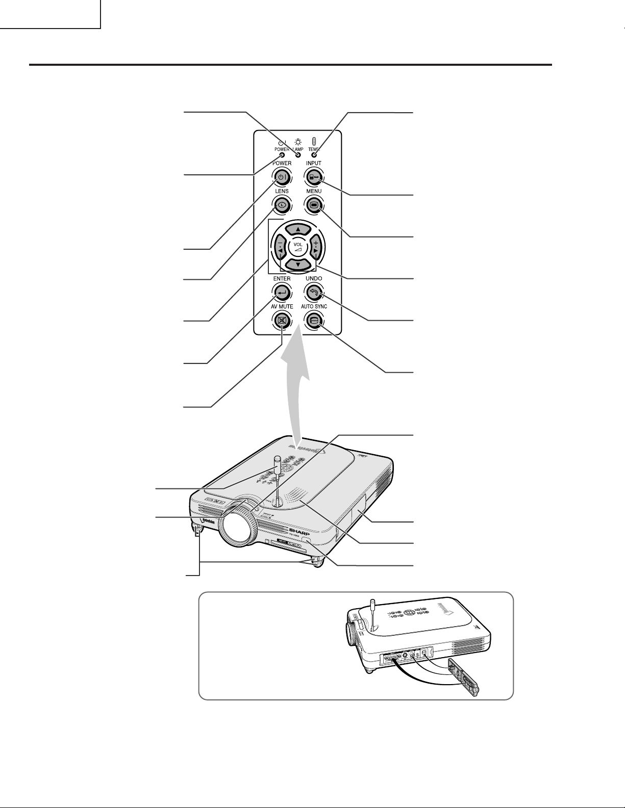
Projector (Front and Top View)
LAMP replacement
indicator
Illuminates in green normally.
Replace the lamp when the
indicator illuminates in red.
POWER indicator
Illuminates in red, when the
projector is in standby. When
the power is turned on, this
indicator will illuminate in
green.
POWER button
Turns the power on or off.
LENS button
For adjusting Keystone or
Digital Shift setting.
Adjustment buttons
(
"'\ |
For selecting menu items.
)
ENTER button
For setting items selected or
adjusted on the menu.
AV MUTE button
For temporarily turning off the
sound and picture.
TEMPERATURE
warning indicator
Illuminates in green
normally. When the
internal temperature
rises, this indicator will
illuminate in red.
INPUT button
For switching input mode
1, 2, 3 or 4.
MENU button
For displaying adjustment
and setting screens.
VOLUME buttons
For adjusting the speaker
sound level.
UNDO button
For undoing an operation
or returning to the default
settings.
AUTO SYNC button
For automatically
adjusting images when
connected to a computer.
Focus ring
GyroRemote
Antenna
Zoom knob
Foot releases/Adjustment
feet
For adjusting the projector’s
height.
Terminal cover
Speaker
Remote control
sensor
Attaching the terminal cover
Attach the terminal cover by
placing it on the side panel of the
projector and pressing it into
place, as shown in the illustration.
8
Page 9
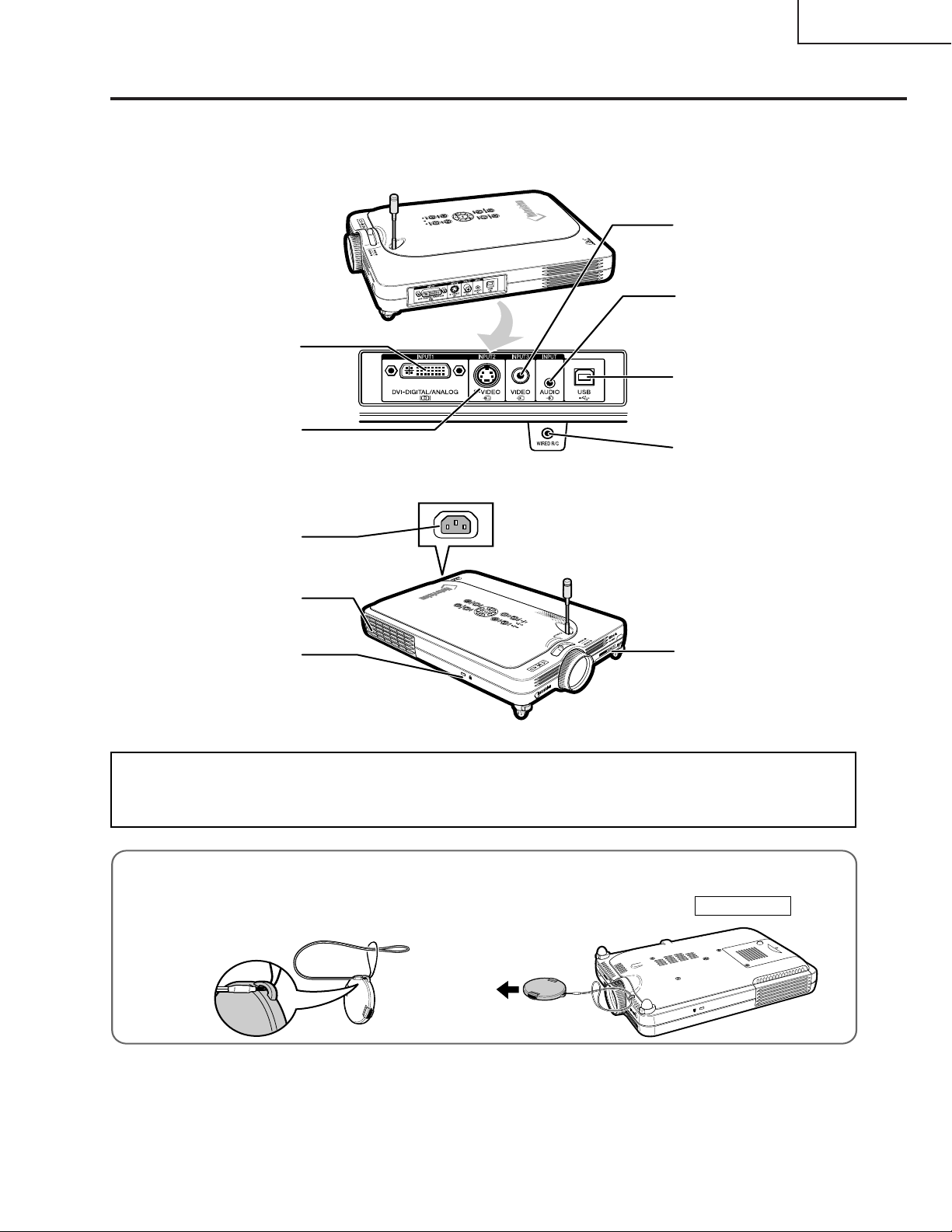
Projector (Side View)
INPUT 1 terminal
Port for DVI digital, computer
RGB, and COMPONENT
signals.
INPUT 2 terminal
Terminal for connecting video
equipment with an S-VIDEO
terminal.
PG-M25X
USB terminal
For connecting a computer
using a USB cable.
INPUT AUDIO terminal
Shared audio terminal for
INPUT 1, INPUT 2,
INPUT 3 and INPUT 4.
INPUT 3 terminal
For connecting video
equipment.
Wired remote contorl
input terminal (ø3.5 mm
minijack)
AC socket
Exhaust vent
Kensington Security
Standard connector
INPUT 4 terminal
For inserting a wireless
LAN PC card or a memory
card.
Using the Kensington Lock
This projector has a Kensington Security Standard connector for use with a Kensington MicroSaver Security
System. Refer to the information that came with the system for instructions on how to use it to secure the
projector.
Attaching the lens cap
After putting the lens cap strap on the lens cap, pass
the other end of the strap through the hole under the
projector, next to the lens, as shown in the illustration.
Bottom View
9
Page 10
PG-M25X
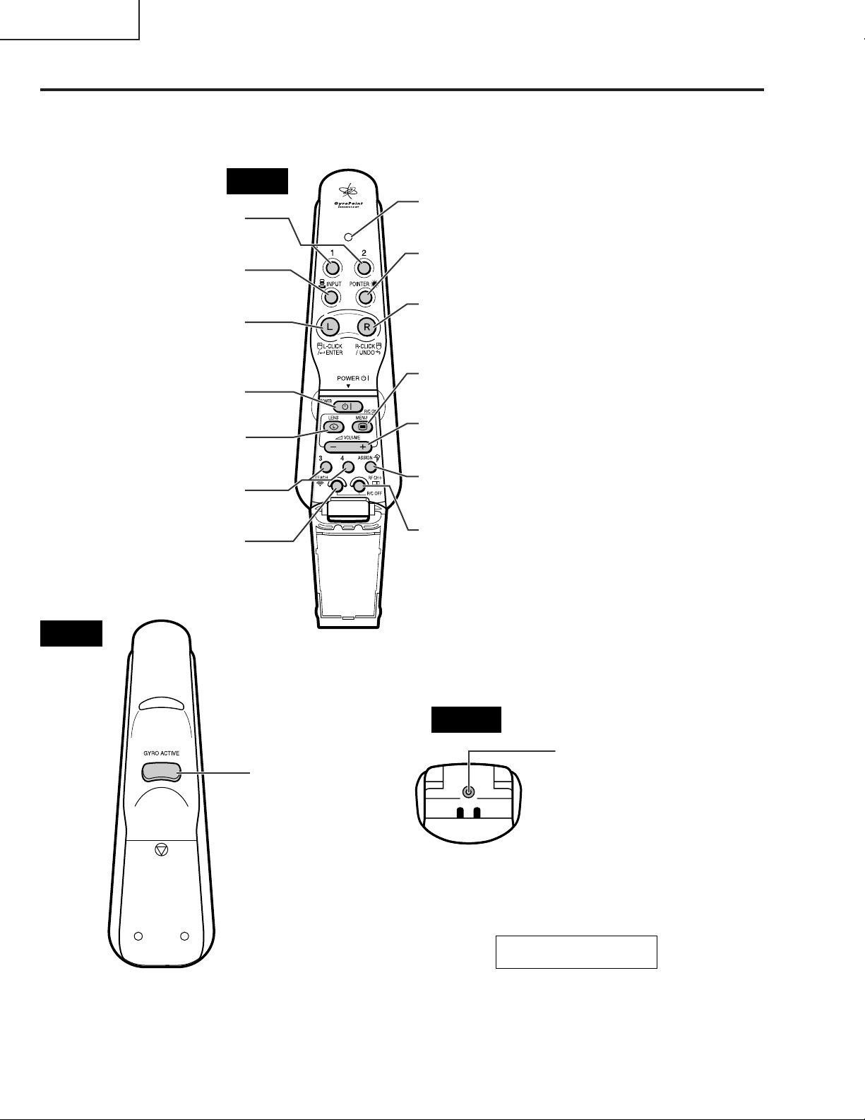
GyroRemote
Function 1 / 2 buttons
For specifying the button assignments
for Function 1 and Function 2
INPUT button
For switching between inputs 1,2,3
and 4.
L-CLICK/ ENTER button
For entering menu items or to perform
a left click when using the
wireless mouse.
POWER button
For turning the power on or off.
LENS button
For adjusting Keystone or Digital Shift
setting.
Function 3 / 4 buttons
For specifying the button assignments
for Function 3 and Function 4
TEACH (OK) button
For registering the GyroRemote in the
projector.
Front
LED indicator
Lights up when the GyroRemote is in
motion.
POINTER button
Holding this button down displays a
pointer on the screen.
R-CLICK / UNDO button
For undoing an operation or to
perform a right click when using the
wireless mouse.
MENU button
For displaying adjustment and
setting screens.
VOLUME buttons
For adjusting the speaker sound
level.
ASSIGN button
Switches the button assignment
function group.
RF CH+ button
For checking the current RF channel
as well as switching the channel.
Rear
GYRO ACTIVE
For moving the Gyro
function for actions such
as moving tool icons
(such as stamp), selecting
menus in the OSD, or
moving the cursor using
the wireless mouse.
Bottom
WIRE R/C JACK
Wired remote
terminal
(ø2.5 mm
minijack)
Gyration U.S. Patents
5698784, 5825350, 5898421
10
Page 11
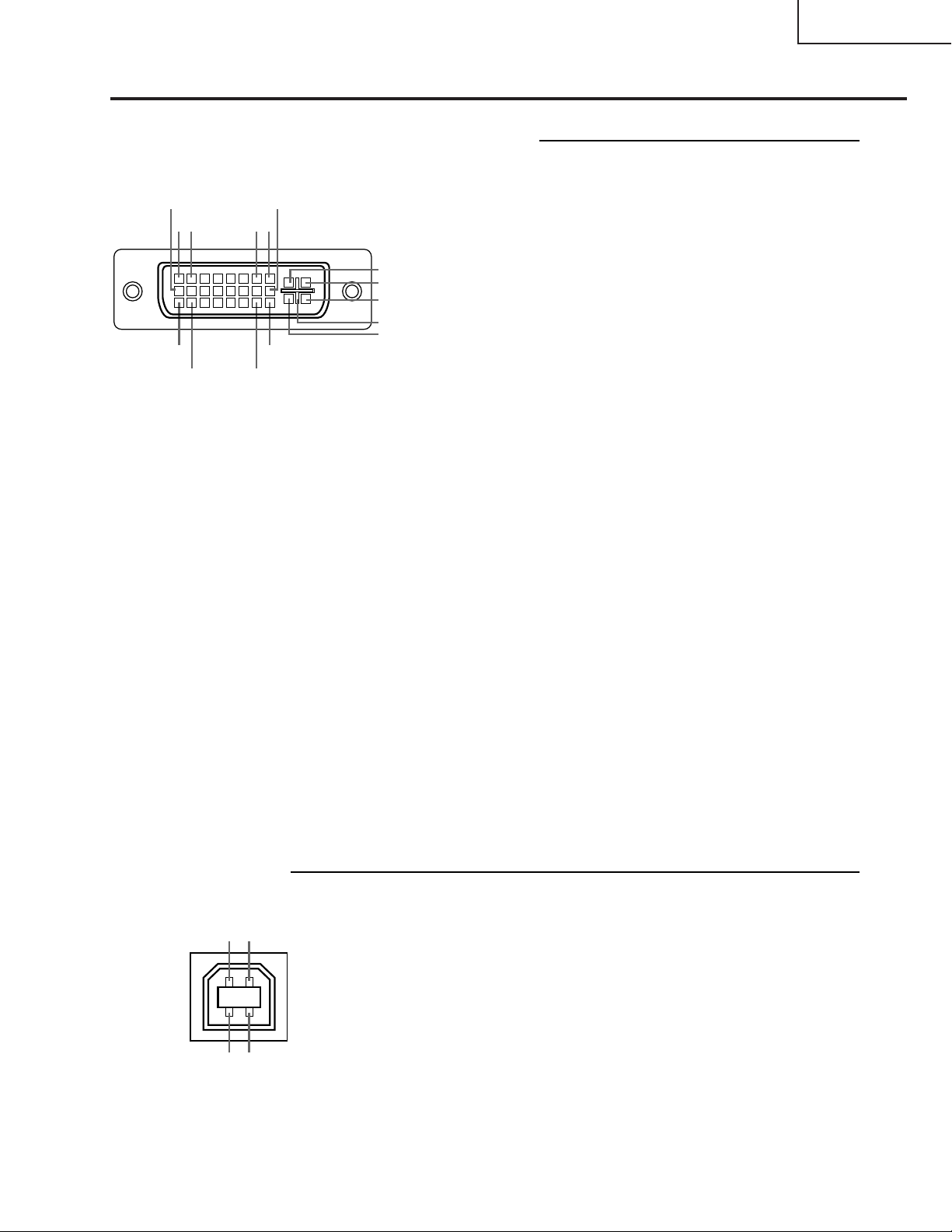
Connection Pin Assignments
DVI Digital / Analog INPUT 1 port : 29 pin connector
• DVI Digital INPUT
•••••••••
9
••••
21
17
••••
18 23
~
~
~
•••••••••
••••
••••
16
87
C1
C2
C4
C5
C3
24
Pin No. Signal Pin No. Signal
10 T.M.D.S data 1+ C1 Not connected
11 T.M.D.S data 1 shield C2 Not connected
12 Not connected C3 Not connected
13 Not connected C4 Not connected
14 +5V current C5 Ground
15 Ground
PG-M25X
1 T.M.D.S data 2– 16 Hot plug detection
2 T.M.D.S data 2+ 17 T.M.D.S data 0–
3 T.M.D.S data 2 shield 18 T.M.D.S data 0+
4 Not connected 19 T.M.D.S data 0 shield
5 Not connected 20 Not connected
6 DDC clock 21 Not connected
7 DDC data 22 T.M.D.S clock shield
8 Not connected 23 T.M.D.S clock+
9 T.M.D.S data 1– 24 T.M.D.S clock–
• DVI Analog RGB Input
Pin No. Signal Pin No. Signal
1 Not connected 16 Hot plug detection
2 Not connected 17 Not connected
3 Not connected 18 Not connected
4 Not connected 19 Not connected
5 Not connected 20 Not connected
6 DDC clock 21 Not connected
7 DDC data 22 Not connected
8 Vertical sync 23 Not connected
9 Not connected 24 Not connected
10 Not connected C1 Analog input Red
11 Not connected C2 Analog input Green
12 Not connected C3 Analog input Blue
13 Not connected C4 Horizontal sync
14 +5V current C5 Ground
15 Ground
4-pin USB connector
12
• USB connector: 4 pin B-type USB connector
Pin no. Signal Name
1 VCC USB current
2 USB– USB data–
3 USB+ USB data+
4 SG Signal Ground
• DVI Analog Component Input
Pin No. Signal Pin No. Signal
1 Not connected 16 Not connected
2 Not connected 17 Not connected
3 Not connected 18 Not connected
4 Not connected 19 Not connected
5 Not connected 20 Not connected
6 Not connected 21 Not connected
7 Not connected 22 Not connected
8 Not connected 23 Not connected
9 Not connected 24 Not connected
10 Not connected C1 Analog input Pr/Cr
11 Not connected C2 Analog input Y
12 Not connected C3 Analog input Pb/Cb
13 Not connected C4 Not connected
14 Not connected C5 Ground
15 Ground
43
11
Page 12
PG-M25X
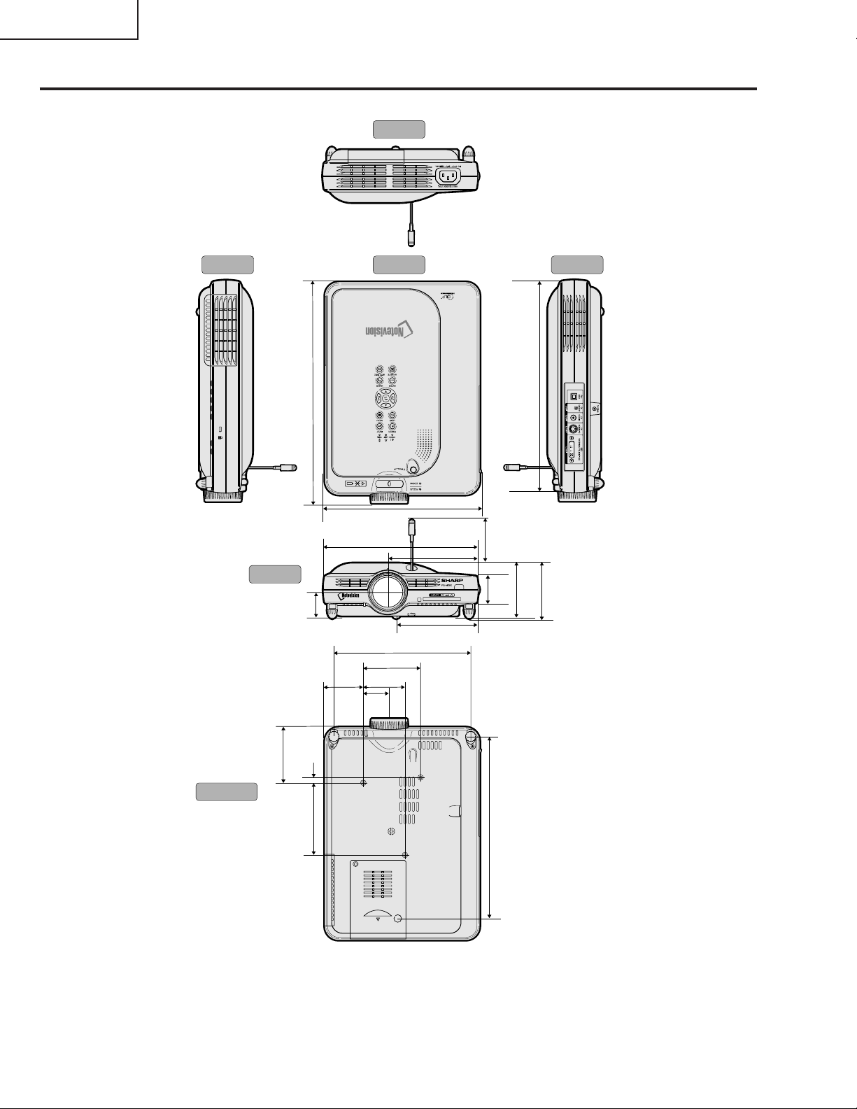
Dimensions
Rear View
Side View Side ViewTop View
17
/
32
12
(318.3)
11 13/
(303)
16
Bottom View
Front View
1
/
8
3
(80)
1
(34.2)
5
/
(7.5)
1
4
(104)
3
8
/4 (223)
5
8
/8 (219)
3
/
8
11
7
1
3
3
2
/16
2
(55.5)
16
/
8
1
1
(37.5)
(60)
/2
/16 (195)
/4 (82.5)
3
/8
1
/16 (128)
5
9
/16 (115.5)
4
45
2
(68.7)
1
1
(38.7)
10
(261.5)
/
64
1
3
3
/
2
5
/
16
(76)
(82.9)
/
4
12
Units: inches (mm)
Page 13
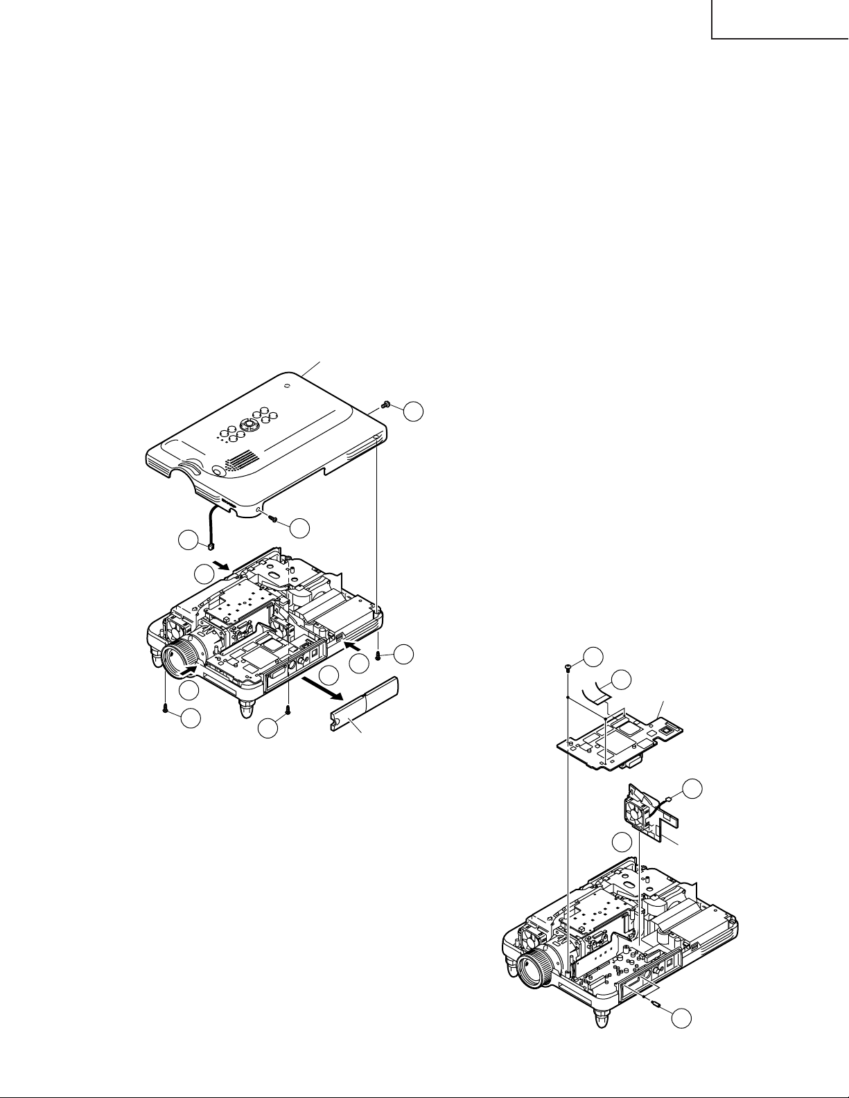
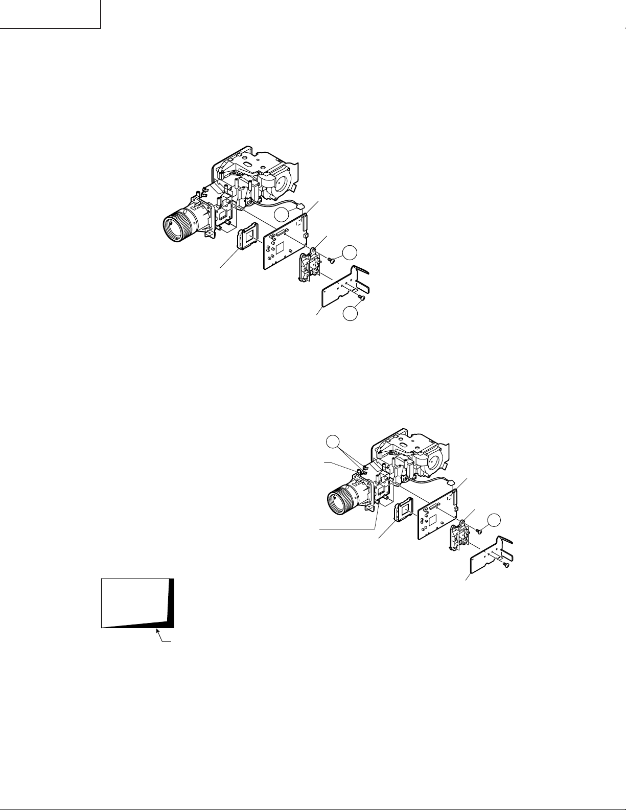
REMOVING OF MAJOR PARTS
1. Removing the top panel
1-1. Detach the terminal block cover.
1-2. Remove the five lock screws from the top panel.
1-3. Press the right side of the bottom body to undo the hook.
1-4. Press the left side of the bottom body to undo the hook.
1-5. Press the front of the bottom body to undo the hook. Get the top panel loose from the bottom body.
1-6. Slightly raise the front of the top panel and disconnect the speaker connector.
2. Removing the PC I/F PWB and cooling fan
2-1. Disconnect the connector.
2-2. Remove the three lock screws from the PC I/F PWB and then the two hex support screws.
2-3. Disconnect the connector and take out the cooling fan.
Top panel
1-2
PG-M25X
1-6
1-5
1-2
1-4
1-2
1-2
1-3
1-1
Terminal block cover
1-2
2-2
2-1
PC I/F PWB unit
2-3
2-3
Cooling fan
13
2-2
Page 14
PG-M25X
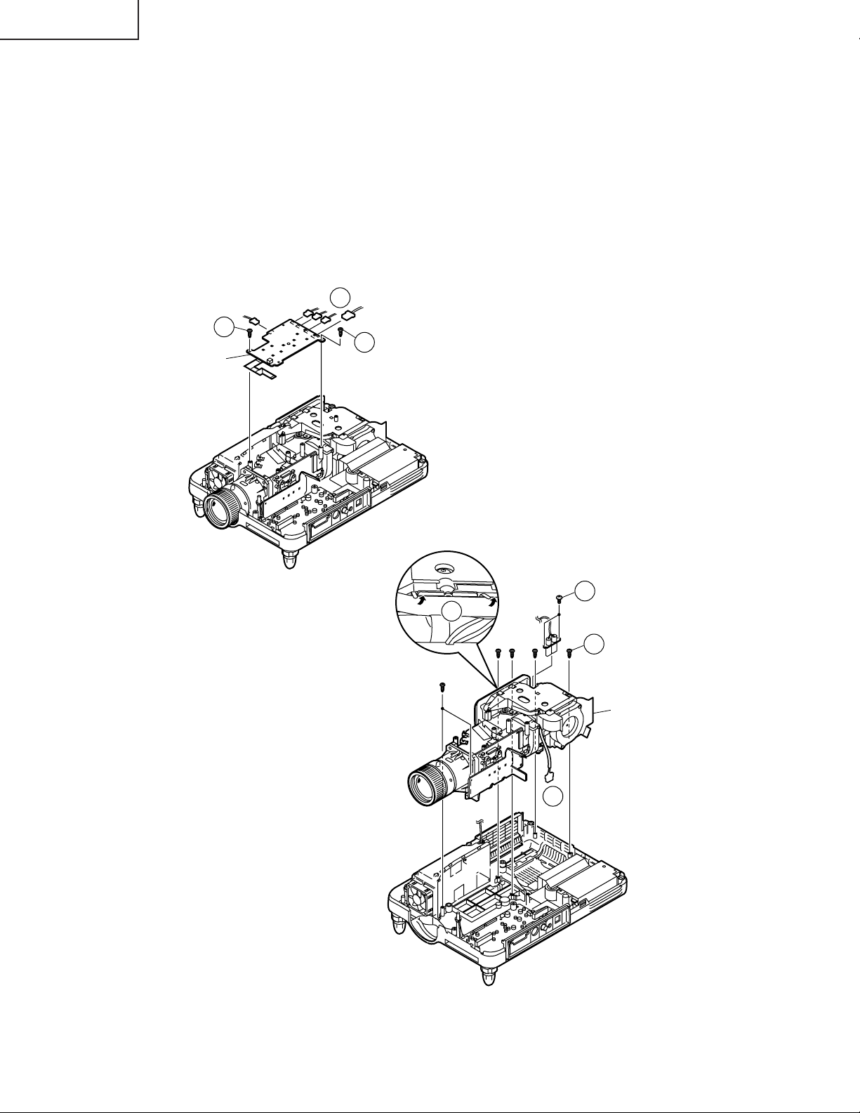
3. Removing the operation PWB
3-1. Remove the two lock screws from the operation PWB and slightly raise this PWB.
3-2. Disconnect the connectors.
4. Removing the optical mechanism
4-1. Remove the two lock screws from the lamp socket.
4-2. Raise the two lamp socket lead fixtures.
4-3. Disconnect the connectors.
4-4. Remove the six lock screws from the optical mechanism.
3-2
3-1
3-1
Operation PWB unit
4-2
4-1
4-4
Optical mechanism
4-3
14
Page 15

5. Removing the other PWBs
5-1. Disconnect the connectors.
5-2. Remove the four lock screws from the power PWB.
5-3. Remove the lock screw from the ballast PWB unit.
5-4. Remove the three hex support screws from the input PWB.
5-5. Remove the lock screw from the terminal block cover.
5-6. Remove the three lock screws from the PFC PWB.
5-7. Remove the one lock screws from the Gyro antenna.
5-8. Remove the three lock screws from the Gyro PWB.
5-4
PG-M25X
Input PWB unit
5-5
5-2
Ballast PWB unit
5-7
Gyro Antenna
Gyro Sub PWB unit
5-3
5-8
Gyro PWB unit
5-1
5-1
5-1
PFC PWB unit
5-6
Power PWB unit
Bottom body
15
Page 16
PG-M25X
ly
FormatterPWBunit
Backerplateassembly
DMD(DigitalMicromirror
Device)chip
+OuterFrame
+C-spring
Heatsink
Prismsurface
Mirroradjusting
plate
1
2
e
6. Removing the formatter PWB
6-1. Disconnect the connector.
6-2. Remove the two lock screws from the heat sink.
6-3. Remove the four lock screws from the backer plate assembly, and detach the formatter PWB.
Note: The DMD (Digital Micromirror Device) unit is easily affected by static electricity. In handling this unit, be sure
to wear a wristband or take other anti-static measure.
FormatterPWBunit
6-1
Backerplateassemb
6-3
DMD(DigitalMicromirror
Device)unit
Precautions in replacing the DMD chip
Note: Be careful not to allow dust and fingerprint
on the cover glass of DMD chip and prism
surface of optical engine.
1. When you fix 4screws of backer plate assemb ly,
press backer plate to formatter PWB and fix
them by cross multiply step by step.
2. If something shade appears on the projection
screen like Fig1, release 2 screws on mirror
adjusting plate and move that plate to adjust
illumination area of DMD chip.
Heatsink
6-2
Fig.1
Shad
16
Page 17
PG-M25X
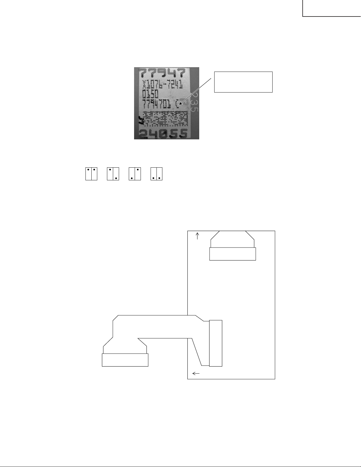
* Precautions in setting up the DMD (Digital Micromirror Device) unit
Before connecting the formatter PWB to the optical engine, take the following steps. Look at the voltage rank marking
that is on the DMD itself. Referring to this marking, set the DIP switches on the formatter PWB. And connect this PWB
to the optical engine. Wrong settings will adversely affect the system performance.
Voltage rank marking
This sample is "C".
Voltage ranking system with the DIP switches on formatter PWB
BCDE
* Connecting the FPC extension cables (QCNW-A298WJZZ)
Connect the cables to the formatter PWB (TO FMT) and the PC I/F PWB (TO PC), referring to the silk-screen-printed
markings. See the sketch below. (The FPC is already connected at TO PC.)
TOFMT
17
TOPC
Page 18
PG-M25X
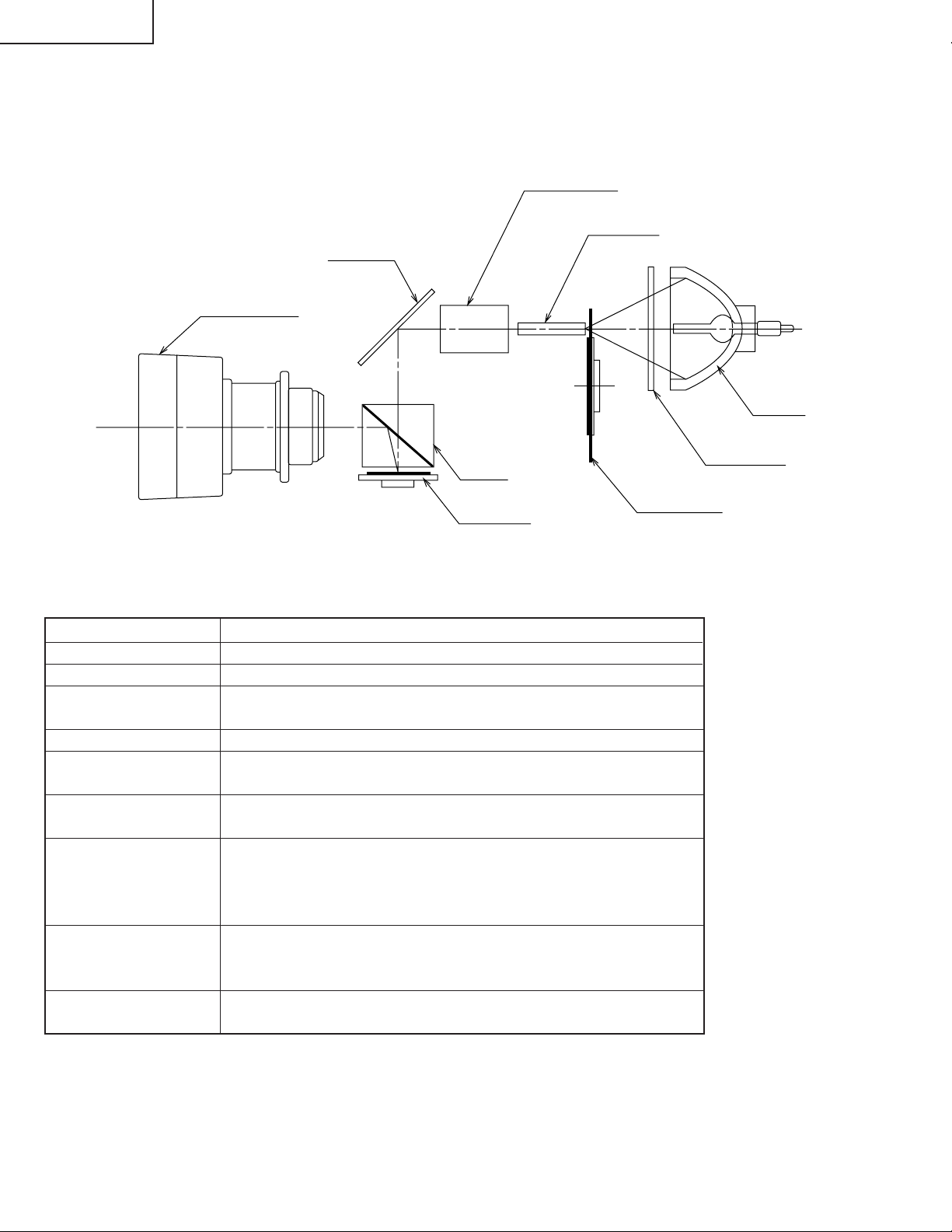
Outline of the optical unit
<Layout>
Projection lens
Relay lenses
Rod lens
Reflector
Lamp
UV/IR filter
Prism
Item
Lamp
UV/IR filter
Color wheel
Rod lens
Relay lenses
Reflector
Prism
DMD chip
Projection lens
DMD chip
Color wheel
Function
Light source. DC-driven high-pressure mercury vapor lamp.
Used to absorb ultraviolet and infrared rays.
Used to let the source light through the color filter and to
separate it into R, G and B colors.
Used to make for uniform light beams.
Used to collect the light from the rod lens into the DMD
chip.
Used to reflect the light from the relay lenses against the
DMD chip.
Used to introduce the light from the reflector over the eff ective surface of the DMD chip. When the micromirror gets
tilted (ON) as specified, the reflected light is guided to the
projection lens.
Used to turn on and off the micromirror in response to the
ratio of color components at each dot and thus to reflect the
incoming light accordingly.
Used to enlarge the light from the DMD chip and to get the
light projected on the screen.
18
Page 19
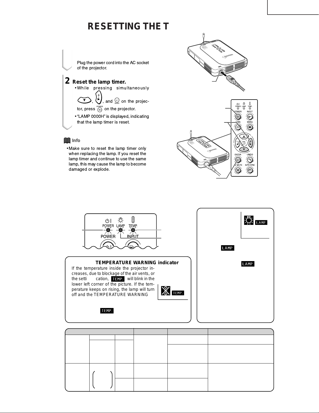
RESETTING THE TOT AL LAMP TIMER
PG-M25X
Resetting the Lamp
Reset the lamp timer after replacing the lamp.
1
Connect the power cord.
•
Plug the power cord into the AC socket
of the projector.
2
Reset the lamp timer.
•
While pressing simultaneously
, , and on the projec-
tor, press
•
ÒLAMP 0000HÓ is displayed, indicating
that the lamp timer is reset.
on the projector.
Timer
AC socket
POWER button
Adjustment buttons
|
|
)
(
Info
•
Make sure to reset the lamp timer only
when replacing the lamp.If you reset the
lamp timer and continue to use the same
lamp, this may cause the lamp to become
damaged or explode.
ENTER button
■ The warning lights on the projector indicate problems inside the projector.
■ If a problem occurs, either the TEMPERATURE WARNING indicator or the LAMP REPLACEMENT
indicator will illuminate red, and the power will turn off. After the power has been turned off, follow
the procedures given below.
TEMPERATURE
WARNING
POWER
indicator
indicator
LAMP
REPLACEMENT
indicator
About the TEMPERATURE WARNING indicator
If the temperature inside the projector increases, due to blockage of the air vents, or
the setting location,
lower left corner of the picture. If the temperature keeps on rising, the lamp will turn
off and the TEMPERATURE WARNING indicator will blink, the cooling fan will run for
further 90 seconds, then the power will be
shut off. After
perform the following measures.
Maintenance indicator Condition Problem Possible Solution
TEMPERA-
TURE
WARNING
indicator
LAMP
REPLACE-
MENT
indicator
Normal Abnormal
Off
Green on
Green
blinks
when the
lamp is
active.
will blink in the
appears, be sure to
Abnormal
The internal
Red on/
Power off
Red
blinks
Red on/
Power off
temperature is
abnormally high.
Time to change
the lamp
The lamp does
not illuminate.
• Blocked air intake
• Cooling fan break-
down
• Internal circuit failure
• Clogged air intake
• Lamp usage time
exceeded 1,900
hours
• Burnt-out lamp
• Lamp circuit failure
LAMP
REPLACEMENT
indicator
■When the lamp
exceeds 1,900 cumulative hours
of use,
on the screen in yellow. When
the cumulative hours of use
reach 2,000,
change to red, the lamp will automatically turn off and then the
projector as well. At this time , the
LAMP REPLACEMENT indicator will illuminate in red.
■If you try to turn on the projector
a fourth time without replacing
the lamp, the projector will not
turn on.
• Relocate the projector to an area
with proper ventilation.
• Take the projector to your nearest
Sharp Authorized Projector Dealer
or Service Center for repair.
• Take the projector to your nearest
Sharp Authorized Projector Dealer
or Service Center for repair or
lamp replacement.
• Please exercise care when
replacing the lamp.
About the
will be displayed
will
19
Page 20

PG-M25X
How to Release the System Lock
Turn on the power. If the system lock is applied, the system-resetting screen appears. Press the following keys in this
order.
MENU → ENTER → ENTER → MENU → UNDO → UNDO → MENU
After pressing the MENU key first, press the remaining six keys within 10 seconds.
20
Page 21
ELECTRICAL ADJUSTMENT
No. Adjustment Items Adjustment Conditions Adjustment Procedures
PG-M25X
1 Initialization of
EEPROM
2 Adjustment of CW
index
3 Adjustment of
RGB gradation
reproduction
1. Tur n on the power (the lamp lights
up) and warm up the system for 15
minutes.
1. Signal input: 64-step color bar
2. Select the following group and subject.
Group: DLP
Subject: Select CW-INDEX.
1. Feed the SMPTE pattern signal.
2. Select the following group and subject.
Group: DLP
Subject: G1-GAIN
1. Carry out the following setting.
Press SW2001 to enter the process
mode, and ex ecute S2 on SSS menu.
1. Feed the signal to INPUT 1.
2. Select subject and make adjustment
so that the lamp gradation patterns
of R, G and B should be smooth without noise.
R
G
B
1. Confirm that 100% and 95% white
gradation, and 0% and 5% black g r adation are discernible.
2. If the white gradation looks differently,
do fine adjustment by G1-GAIN.
4 Adjustment of
video brightness/
contrast
5 Adjustment of
video tint
1. Feed the NTSC100% window patter signal. (Burst signal)
2. Select the following group and subject.
Group: VIDEO
Subject: AUTO
1. Feed the split color bar signal.
2. Select the following group and subject.
Group: VIDEO
Subject: TINT
21
1. After signal input, select AUTO using the set's switch or the remote
controller's button for automatic adjustment.
1. Confirm the fixed value.
Fixed value: 128
Page 22

PG-M25X
No. Adjustment Items Adjustment Conditions Adjustment Procedures
6 Adjustment of
NTSC color
saturation
7 Adjustment of PAL
color saturation
8 Adjustment of
SECAM color
saturation
9 Adjustment of
COMPO G brightness
1. Feed the internal 8ch (split color bar)
signal.
2. Select the following group and subject.
Group: VIDEO
Subject: N-COLOR
1. Feed the PAL color bar signal.
2. Select the following group and subject.
Group: VIDEO
Subject: P-COLOR
1. Feed the SECAM color bar signal.
2. Select the following group and subject.
Group: VIDEO
Subject: S-COLOR
1. Input signal: 0% gray pattern signal (480I)
2. Select the following group and subject.
Group: COMPO
Subject: G-BRIGHT
1. Confirm the fixed value.
Fixed value: 59
1. Confirm the fixed value.
Fixed value: 59
1. Confirm the fixed value.
Fixed value: 59
1. Feed the signal to INPUT 1.
Make adjustment so that some bits
should be missing in the picture.
10 Adjustment of
COMP CR-Offset
11 Automatic Adjust-
ment of RGB
white balance
12 Automatic Adjust-
ment of SRGB
white balance
1. Feed the color difference signal
(480I): Y 0% brightness, Cb and Cr
0% white patterns.
Group: COMPO
Subject: AUTO
1. Feed the 50% gray pattern signal
(XGA, 60 Hz).
2. Select the following group and subject.
Group: DLP
Subjects: R1-GAIN (Red)
B1-GAIN (Blue)
1. Feed the 50% gray pattern signal
(XGA, 60 Hz).
2. Select the following group and subject.
Group: DLP
Subjects: S-R1-GAIN (Red)
S-G1-GAIN (Green)
S-B1-GAIN (Blue)
1. After signal input, select AUTO using the set's switch or the remote
controller's button for automatic adjustment.
1. Adjust R-1 GAIN and B1-GAIN so that
x-value should be 266±3 and y-value
320±3.
1. Set the value of S-R1-GAIN to 34.
2. Adjust S-G1-GAIN and S-B1-GAIN
so that x-value should be 310±3 and
y-value 335±3.
22
Page 23

No. Adjustment Items Adjustment Conditions Adjustment Procedures
PG-M25X
13 Automatic adjust-
ment of video
white balance
14 Automatic adjust-
ment of DTV white
balance
15 Adjustment of
DLP voltage (For
reference)
1. Feed the 50% gray pattern signal
(NTSC, burst signal).
2. Select the following group and subject.
Group: DLP
Subjects: V-R1-GAIN (Red)
V-B1-GAIN (Blue)
1. Feed the 50% gray pattern signal
(480I, color difference signal).
2. Select the following group and subject.
Group: DLP
Subjects: C-R1-GAIN
C-B1-GAIN
1. Read voltage rank of DLP description.
2. Set the switch corresponding to the
rank which has been read. (on the
formatter PWB)
1. Adjust V -R1-GAIN and V-B1-GAIN so
that x-value should be 265±3 and yvalue should be 298±3.
1. Adjust C-R1-GAIN and C-B1-GAIN
so that x-value should be 263±3 and
y-value should be 295±3.
1. Carry out adjustment when DLP chip
has been replaced or combination of
chip and formatter has been changed.
2. Rank: BCDE
Setting value: 1234
16 Frequency adjust-
ment
17 Frequency check-
ing
18 W/A selection
checking
19 Output waveform
checking
1. Tur n on the power.
2. Adjust the frequency at TP5801 to
12800000±40 Hz.
1. Tur n on the power. 1. Make sure the frequency at TP5801
Send the signal using the remote controller that is for the North American
and European markets.
1. Be sure to keep on power.
2. T ak e the frequency reading at TP5801
and readjust the trimmer capacitor
(C5835), as required, to the specified frequency level.
is 12800000±40 Hz.
1. Set the W/A terminal to the "L" level.
2. Connect the wired remote control
cable between the set and the remote controller.
3. Make sure the remote controller functions as specified.
Watch the oscilloscope screen to make
sure the serial data output is as specified.
20 Hooked-up in-
spection
Hook up the unit to the projector. Make
sure that the remote controlled registration functions well and that the
pointer moves accordingly.
23
Gyro remote controller performance
checking.
Page 24
PG-M25X
No. Adjustment Items Adjustment Conditions Adjustment Procedures
21 Confirmation and
re-adjustment of
white balance
22 Confirmation of
color-related
operation
23 Confirmation of
picture-related
operation
24 Confirmation of
RGB
25 Confirmation of
off-timer operation
1. The adjusting conditions for each
item are as follows:
For RGB input, see Item 11
For SRGB input, see Item 13
For video input, see Item 14
For DVT input, see Item 12
1. Receive the color bar signal. 1. Select L1 in the process mode.
1. Receive monoscope pattern signal. 1. Select L2 in the process mode.
1. Receive the RGB signal. 1. Select L4 on the process mode.
Confirm that there is no deviation in white
balance from that of the monitoring
equipment.
For readjustment, proceed in the order
of RGB input, video input and DTV input.
Check the performance of color and
tint.
Check Picture, Brightness and Sharpness.
Check Picture, Brightness, Red, Blue,
Clock, Phase, H-POS and V-POS.
1. Select OFF in the process mode.
Confirm that the off-timer star ts with
5-minute display, counts 1 minute for
1 second, and turns off when 0 minute
is displayed.
26 Confirmation of
thermistor operation
27 Automatic sync
operation
28 Gyro remote
controller performance checking
29 PC card perfor-
mance checking
30 Factory settings 1. Receive the phase checking pattern
1. Heat the thermistor by dryer. 1. Confirm that the temperature is dis-
1. Receive the phase checking pattern
signal.
1. Insert the wireless LAN card into the
PC card slot.
2. Then insert the memory card with
the test pattern images into the PC
card slot.
signal.
played.
1. Confirm that Clock, Phase, H-POS
and V-POS can be automatically
adjusted in the VGA/S-VGA/XGA
mode.
Make sure the Gyro remote controller
functions as specified.
1. Make sure the image can be properly transferred.
2. Make sure the image can be properly displayed.
1. Make the following settings.
Process
adjustment
S4
2. Register the Gyro remote controller
that is shipped together.
Remote control
setting
Factory setting 4"
24
Page 25

How to Adjust the PC I/F unit
1. Initialization of EEPROM
1) Press SW2002 to enter the process mode.
2) Execute S1 on the SSS menu. (By S1, all the contents of EEPROM are initialized.)
3) Confirm that the program version "Ver. XXX" has become the latest one
2. Adjusting items
1) Adjustment of RGB drive/gain
(1) feed the window pattern signal that has 100% and 0% signals.
(2) Select AUTO among the A/D items in the process mode and carry out adjustment.
PG-M25X
25
Page 26

PG-M25X
» Entering the adjustment process mode
There are follwing two methods.
» Press the SW2001 on the KEY PWB unit.
» Press the follwing keys in this order.
AV MUTE→AV MUTE→Adj up→Adj down→ENTER→ENTER→MENU
» Adjustment mode process menu
Group Sub Group Subject
Adjust PC Image A/D R-BRIGHT
G-BRIGHT
B-BRIGHT
R-D
B-D
G-D
AD-AUTO
Adjust DLP Image DLP R1-BLK
R1-GAIN
G1-BLK
G1-GAIN
B1-GAIN
CW-INDEX
S-R1-GAIN
S-G1-GAIN
S-B1-GAIN
C-R1-GAIN
C-B1-GAIN
V-R1-GAIN
V-B1-GAIN
Adjust VIDEO Image VIDEO PICTURE
BRIGHT
TINT
N-COLOR
P-COLOR
S-COLOR
STAT-GAIN
VIDEO-AUTO
Adjust Component Image DTV G-BRIGHT
CB-OFFSET
CR-OFFSET
COMPO-AUTO
Process mode LINE L1
L2
L3
OFF
TEMP OFF
SENSOR CHECK
INTIAL SETTING SSS TIME
S1
S2
S3
S4
S5
26
Page 27
Group Sub Group Subject
Sample Pattern PATTERN RGB
RGB(50)
CROSS
FOCUS
SETP
COLOR
CHR
Adjust CVIC CVIC-PROGRSSIVE MODE
IP
MDSW
PTGSW
C-TESTSW
C-ILG-LY
C-MOD-LY
C-VE-LV
CVIC-ENHANCE-VIDE ENH-PLUS
ENH-MINUS
DFC
CVIC-ENHANCE-HTTV ENH-PLUS
ENH-MINUS
DFC
CVIC-ENHANCE-RGB MODE
ENH-GAIN
ENH-PLUS
CVIC-SCREEN CUBIC-RGB
CUBIC-VEDEO
CVIC-NR YNR-LEVEL
YNR-K
YNR-FSEL
CNR-LEVEL
CNR-K
CNR-FSEL
CNR-FILSW
CVIC-PTG TESTSW
ENABLE
MV-F
VDDTP
CVIC-CMS RED
YELLOW
GREEN
CYAN
BLUE
MAGENTA
CVIC-DEGAMMA TABLE
Version Check etc Special IPL
IPL2
E2PROM
ADR RD/WR
USB-MODE
PG-M25X
27
Page 28
PG-M25X
How to write in a Serial number.
Install the new program for the software into your PC
a.This software is downloaded from home page of SHARP intranet.
http://172.24.145.13/tcg-qrc/prj/prj-e.asp
NAME:USB to Sirial Driver program.
STEP 1
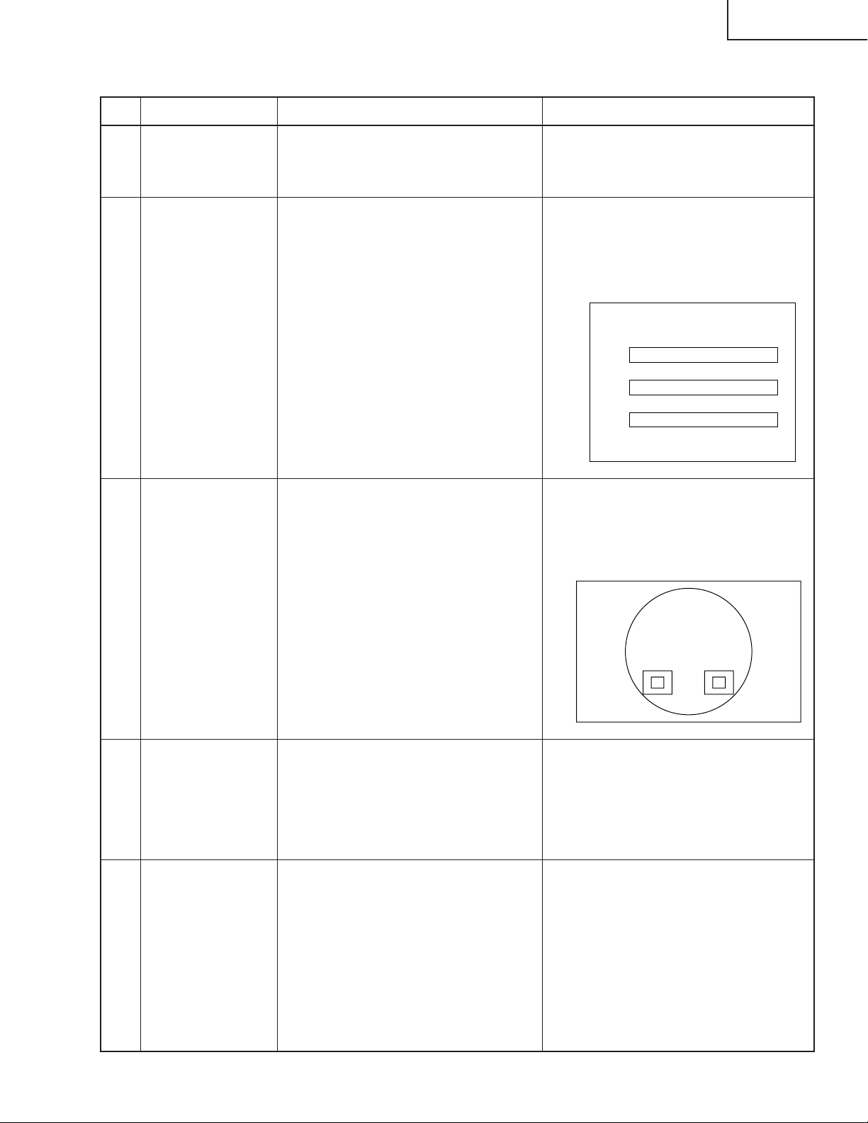
Set-up for USB Serial Driver
(Refer to "Installation Process and advice.doc " file.)
STEP 2
Call the adjustment process mode, and select the sub-group "SPECIAL" and the adjustment item
"USB-MODE". Change the USB MODE value from 0 to 1.
(With this change, input of a 232C command becomes possible.)
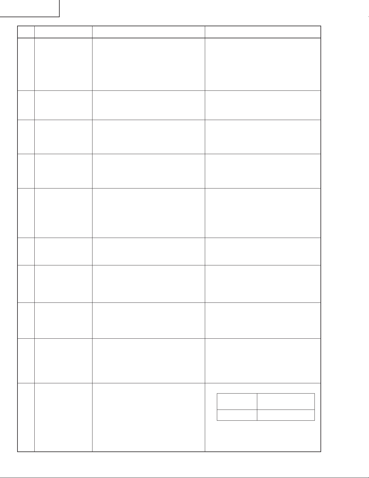
STEP 3
Please connect the USB cable between the PC and the projector.
STEP 4
Please execute the program "TeraTerm".
(configuration file is to use attached Teraterm.ini.)
STEP 5
You write it by using the attached macro-file (serial_write.ttl).
A serial number is described in this macro-file. Enter this number.
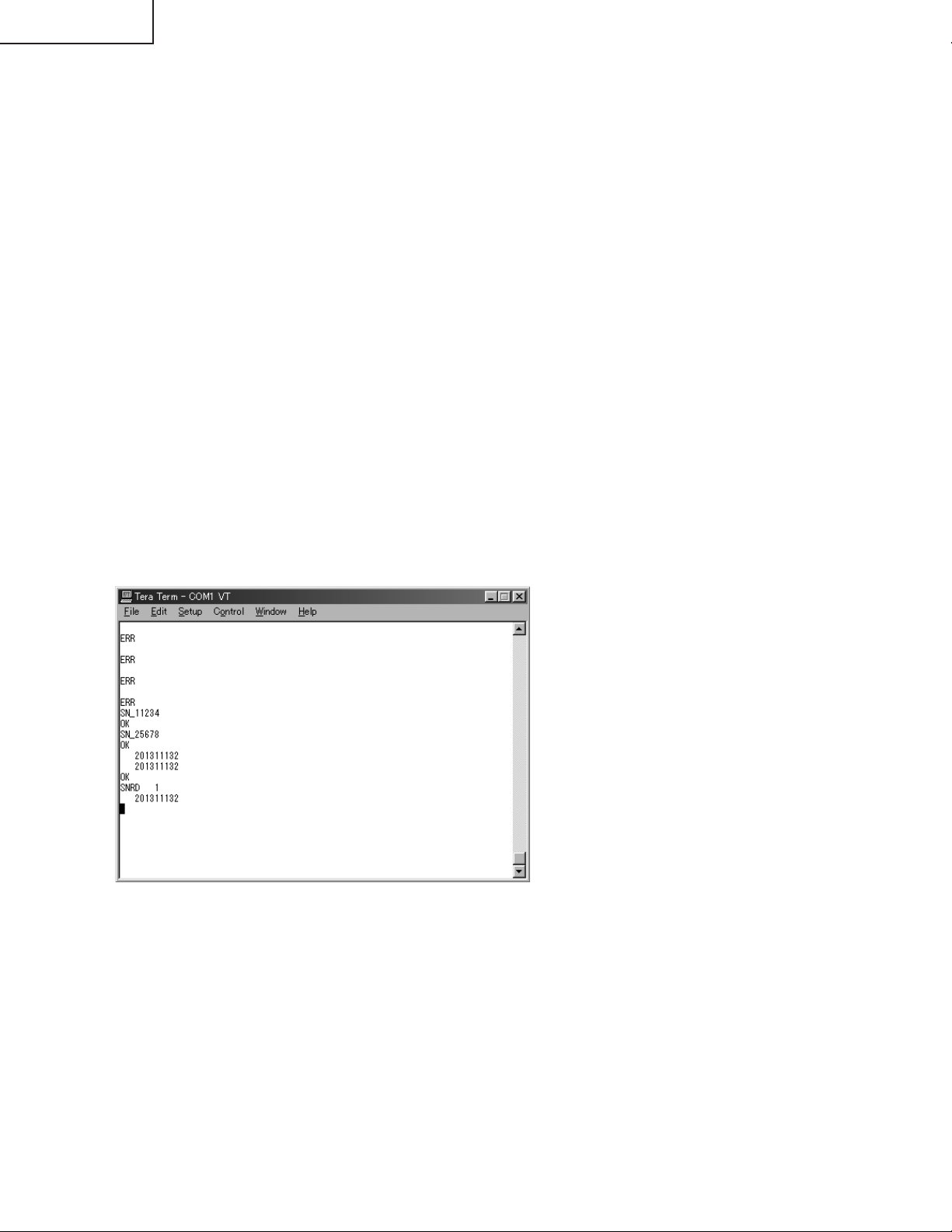
STEP 6
Message will be appear as follows,
STEP 7
Please finish TeraTerm.
STEP 8
Please change the value from 1 to 0 for USB MODE in Special (Factory mode).
(For this change, input of a 232C command becomes invalid.)
<Attention >
After the installation for USB to 232C driver, select the 232C with SW2002 on the KEY unit.
Connect the USB cable, and change COM2 for teraterm(setup-serial port) then push "Enter" key
and confirm "ERR" message comes back.
If "ERR" comes back setting is correct. In case of "ERR" does not come back, COM2 is incorrect.
Please try COM3, COM4 by turn, and find correct COM port.
28
Page 29
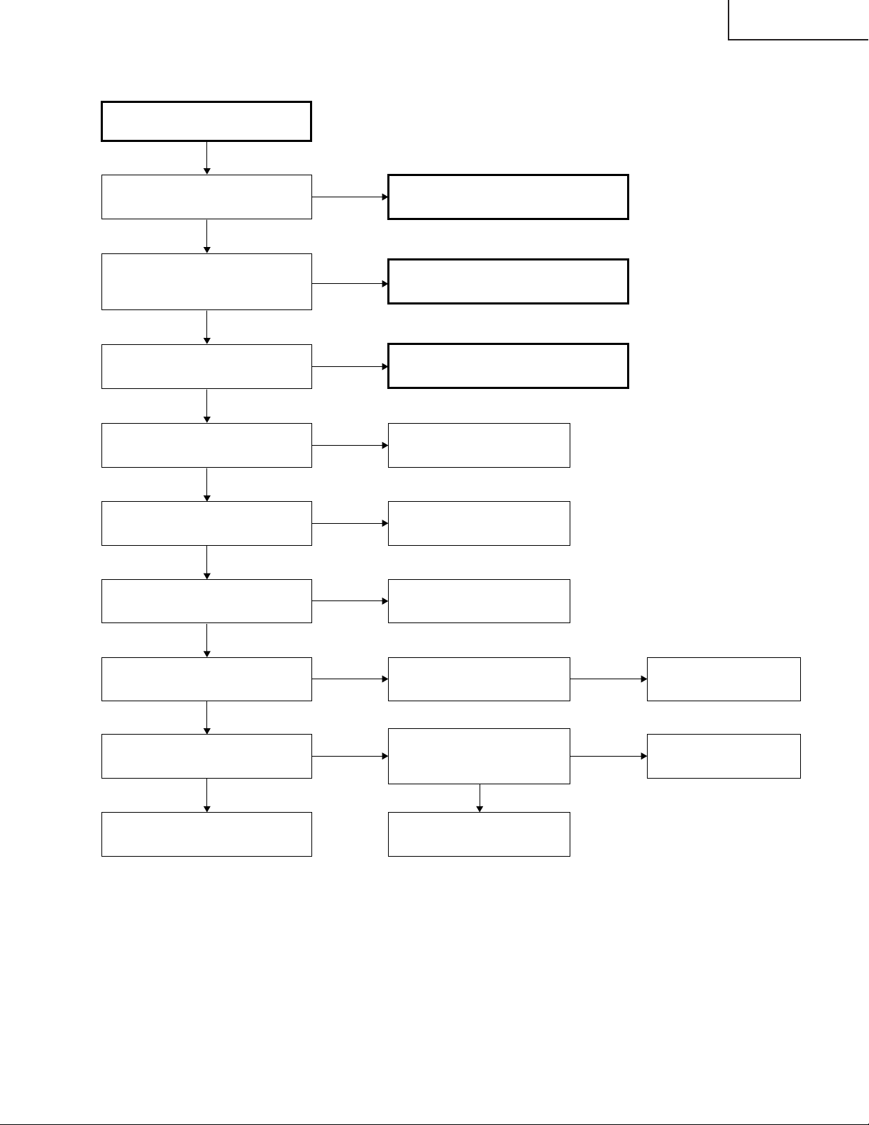
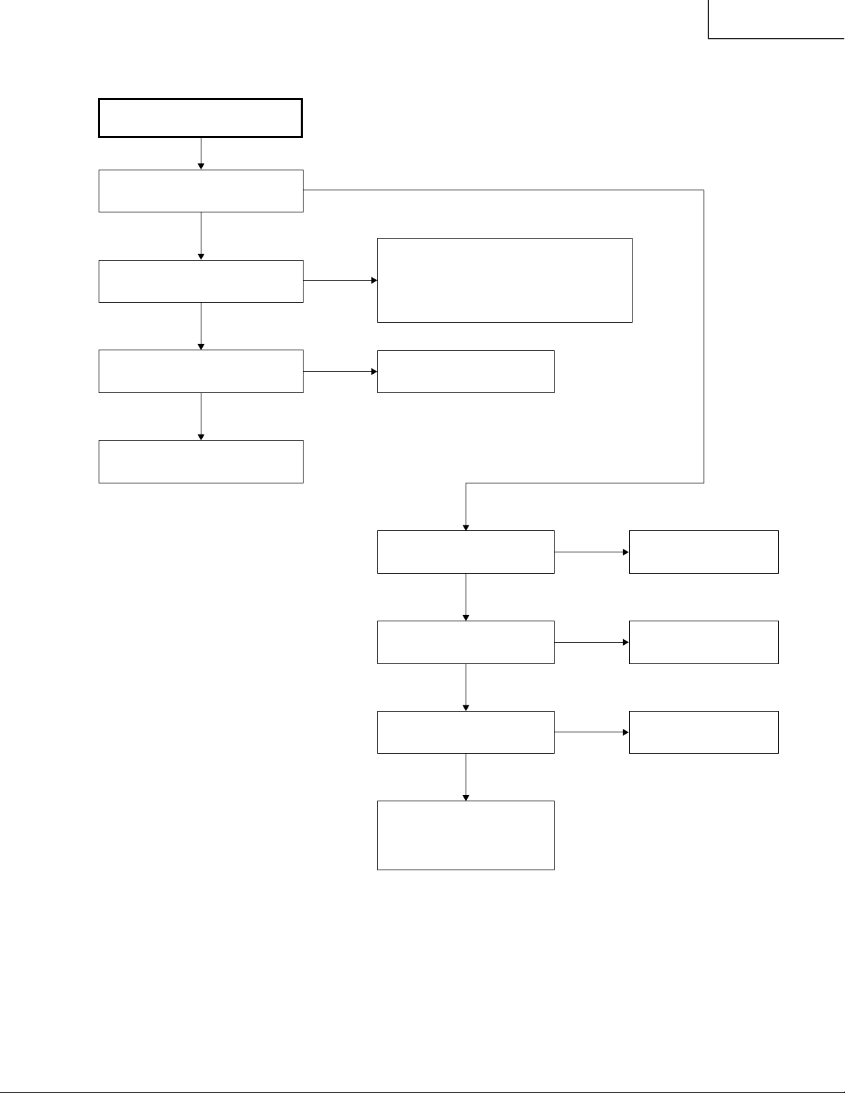
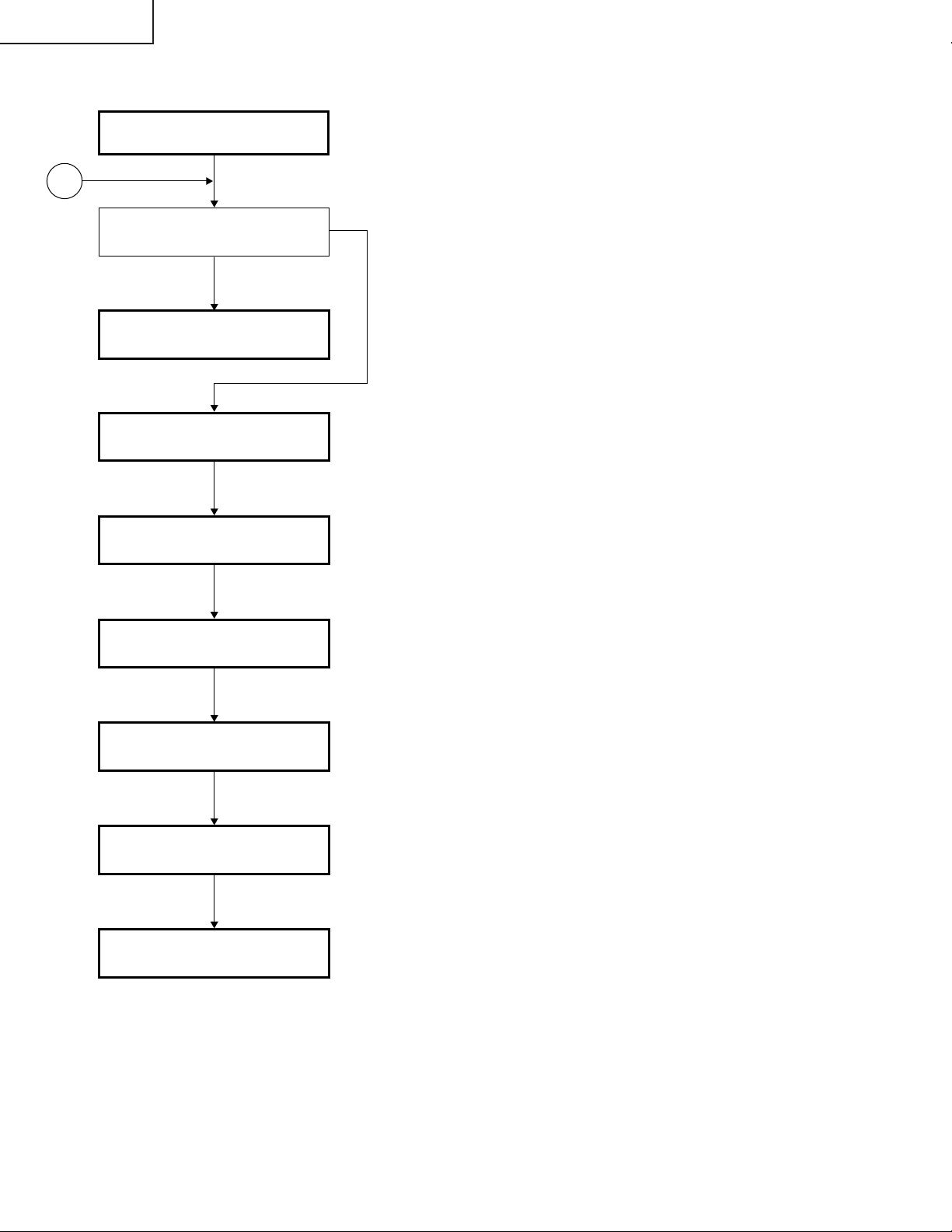
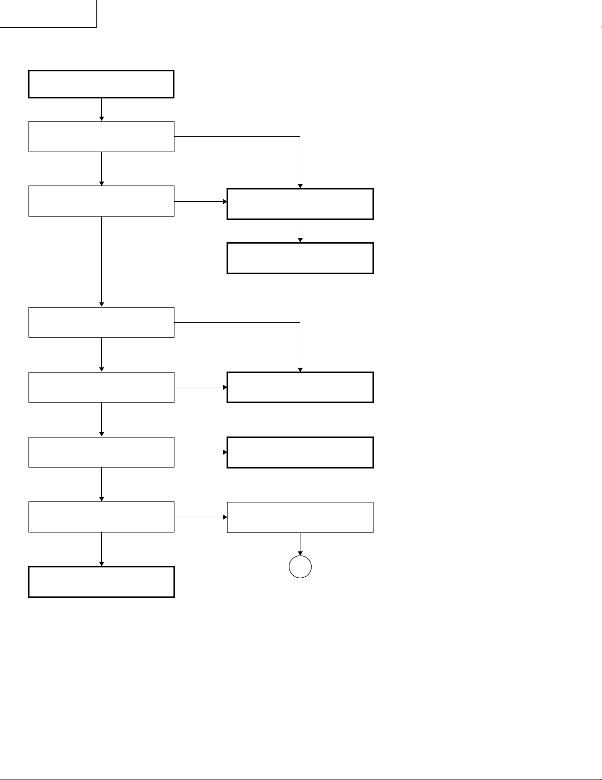
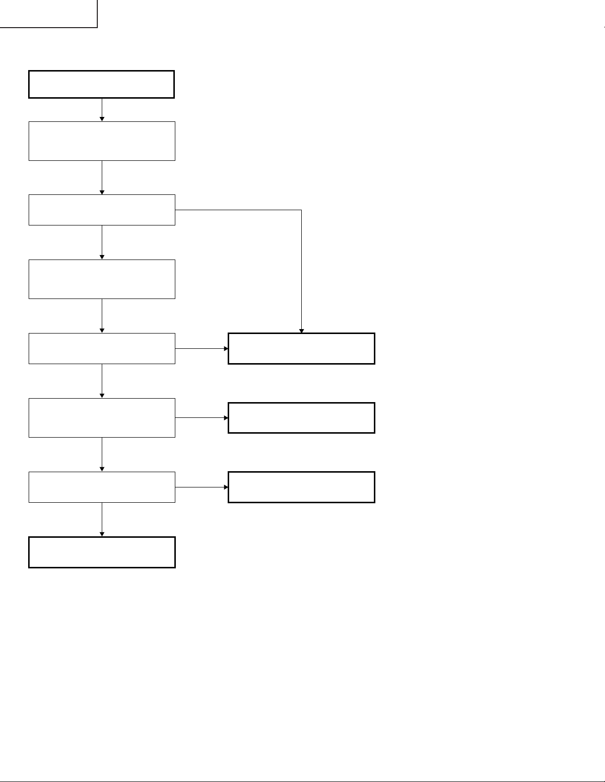
Checking of Basic Operation
PG-M25X
TROUBLE SHOOTING TABLE
Does the POWER LED light up or
flicker in red or green?
Yes
Does the set operate by the set's
key or the remote controller's
power key?
Yes
Does the cooling fan rotate and
does the lamp light up?
Yes
Is the user menu displayed?
Yes
Does the RGB input operate
normally?
Yes
Does the video input operate
normally?
Yes
No
No
No
No
No
No
Go to "Checking of Power Unit".
Go to "Checking of Sub-microprocessor
and Its Periphery"
Go to "Checking of Lamp Lighting-up"
Check the formatter circuit and
its periphery.
Check IC8013 (AD) and go to
"Checking of RGB Input".
Check IC8015 and peripheral
circuit.
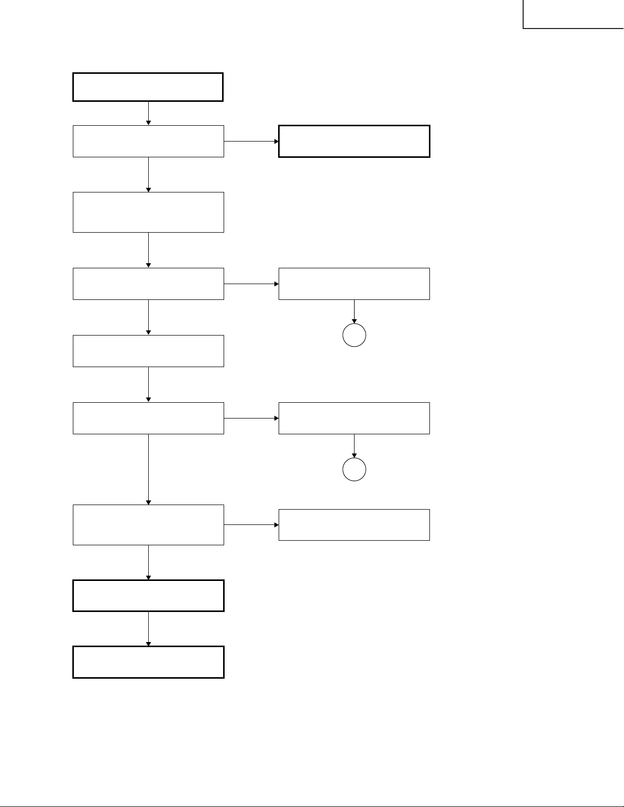
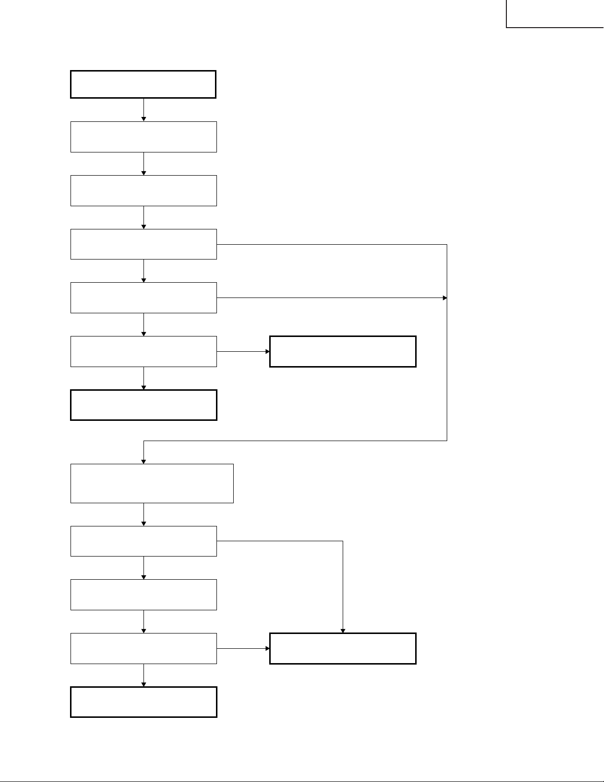
Do the component input/DVI input
operate normally?
Yes
Does the DVI input operate
normally?
Yes
End
No
No
Is there input signal at pins
(8), (17) and (23) of IC8013?
Go to "Checking of Video
Input". Is there input signal at
the emitter of Q8002?
Yes
Check IC8015 and its
peripheral circuit.
No
No
Check IC3851 and its
peripheral circuit.
Check IC3502 and its
peripheral circuit.
29
Page 30
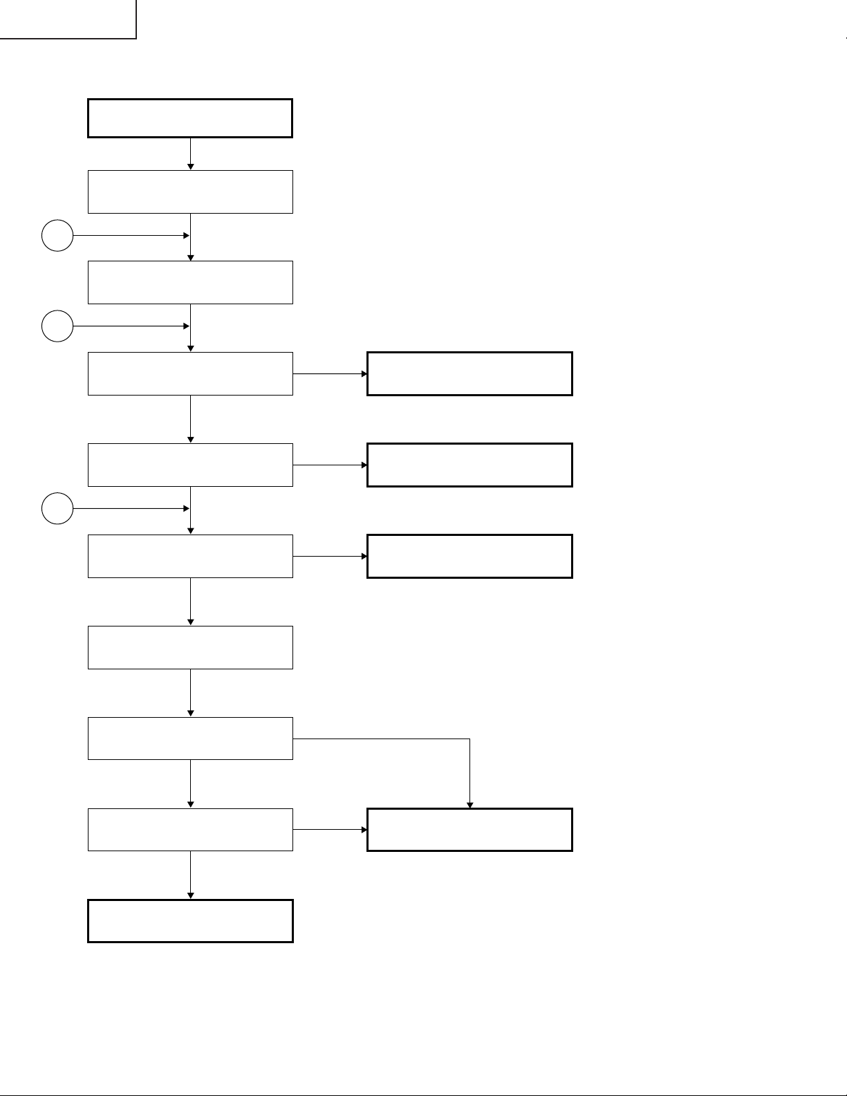
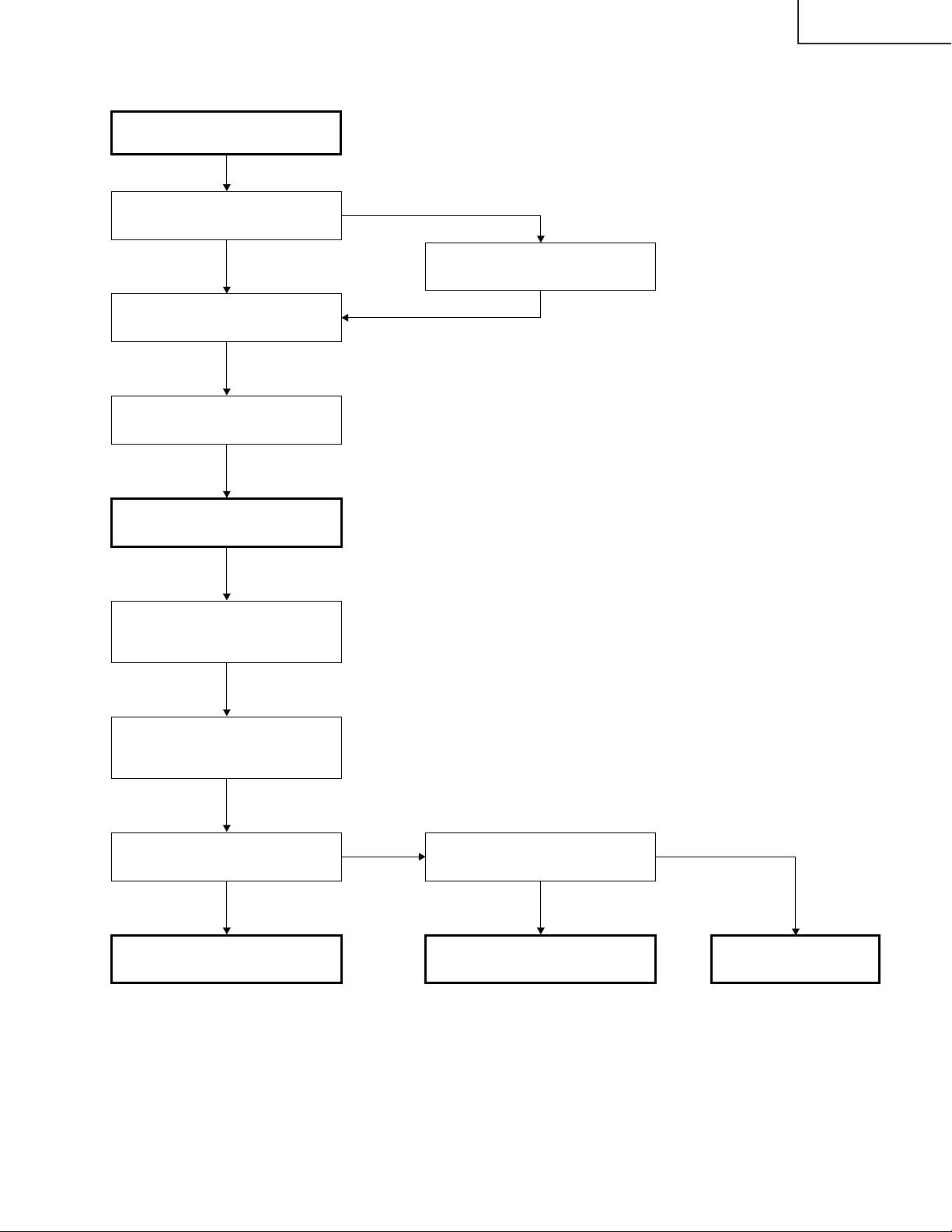
PG-M25X
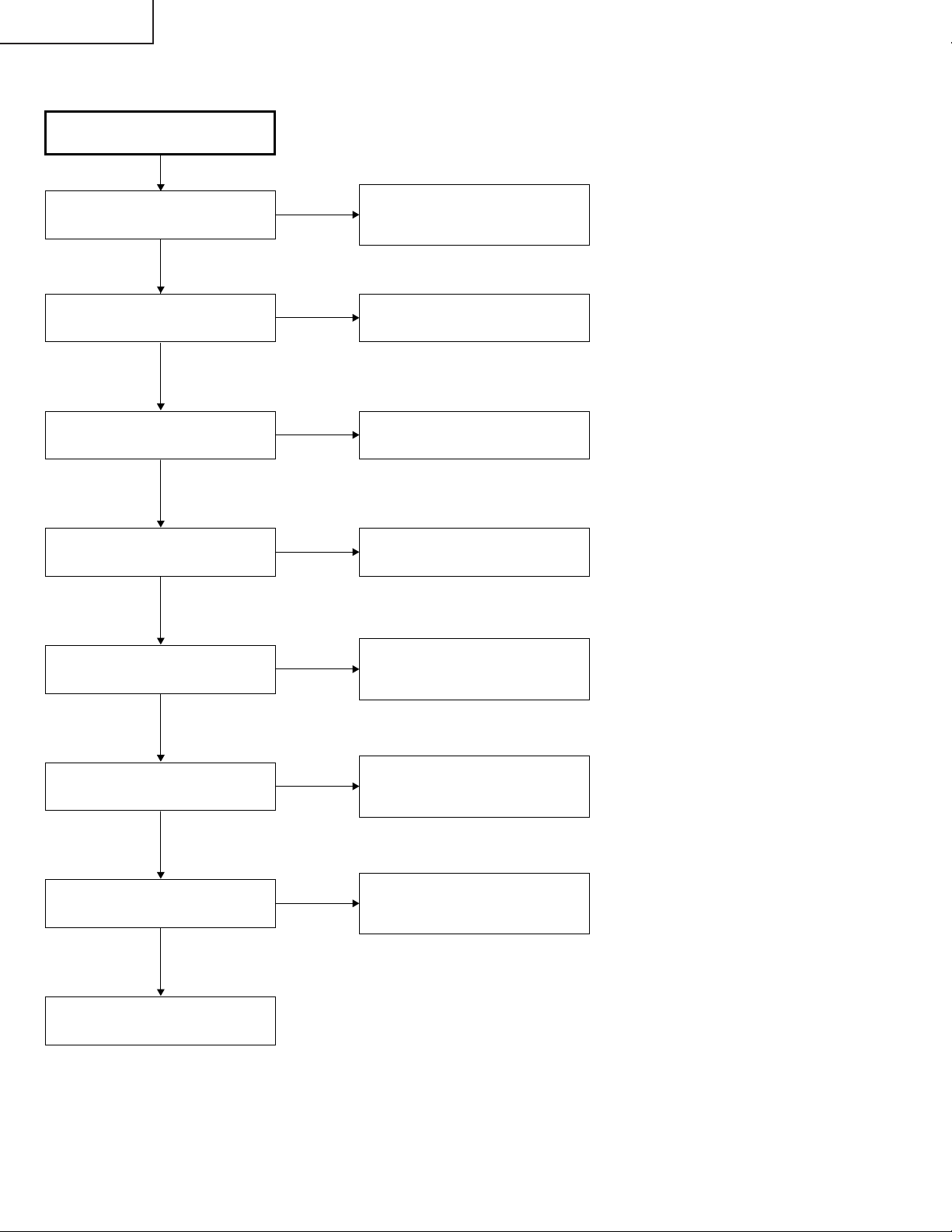
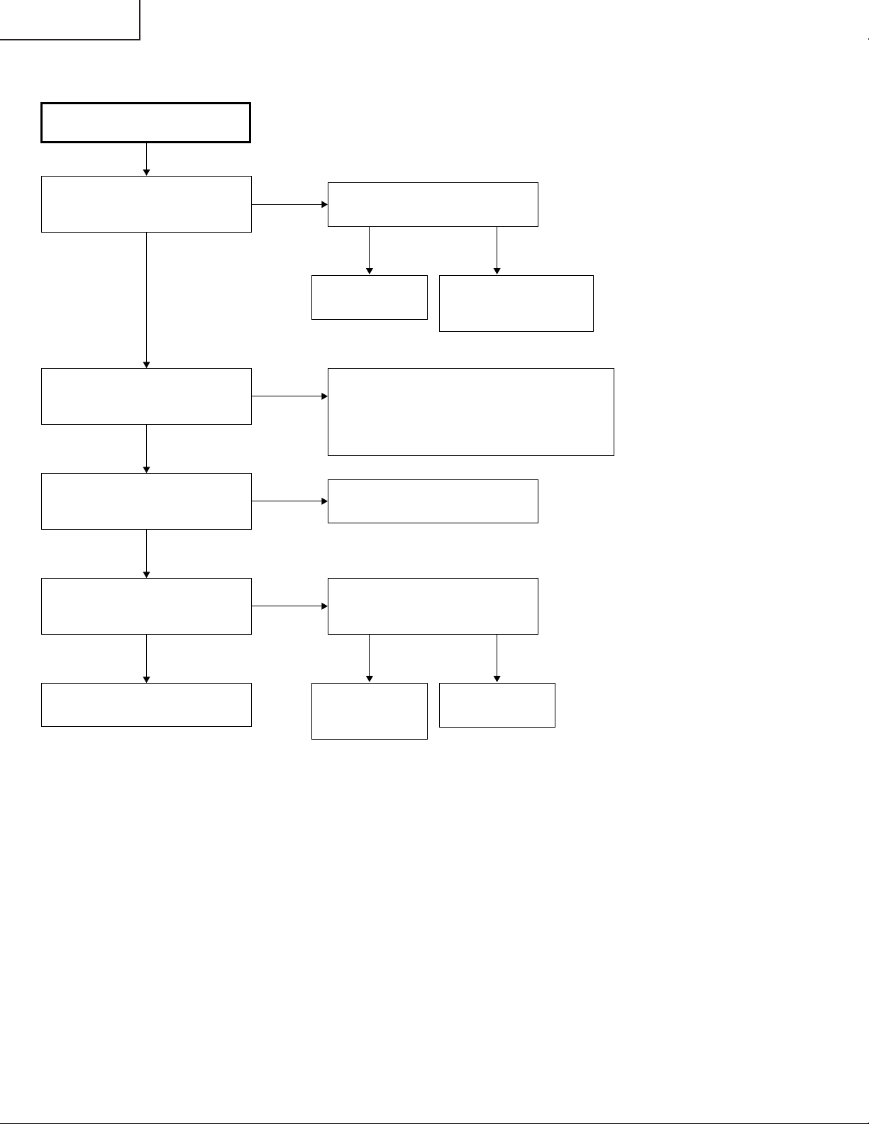
Checking of Power Unit
Are connectors in the power unit
completely inserted?
Yes
Is the lamp door closed
completely?
Yes
Does the temperature
fuse function?
Yes
Is AC voltage applied across relay
RL701?
Yes
No
No
No
No
Insert the connectors CN702,
CN704, CN7003, CN7001,
CN7004 and CN7101 completely.
Close the lamp door completely by
screws.
Replace the fuse as well as its
harness.
Replace F701.
Is there DC voltage of about 6V at
pin (1) of CN7002?
Yes
Is there DC voltage of about 370V
across CN702?
Yes
Is there rated voltage at the output
terminals of CN702 and CN7102?
Yes
Check the PWB circuits of relevant
output sides.
No
No
No
Check Q7501, Q7502 and Q7503
and their peripheral circuits. If any
circuit is damaged, replace it.
Check the circuits connected to the
primary side of T701. If any circuit
is damaged, replace it.
Check the circuits connected to the
secondary side of T701. If any
circuit is damaged, replace it.
30
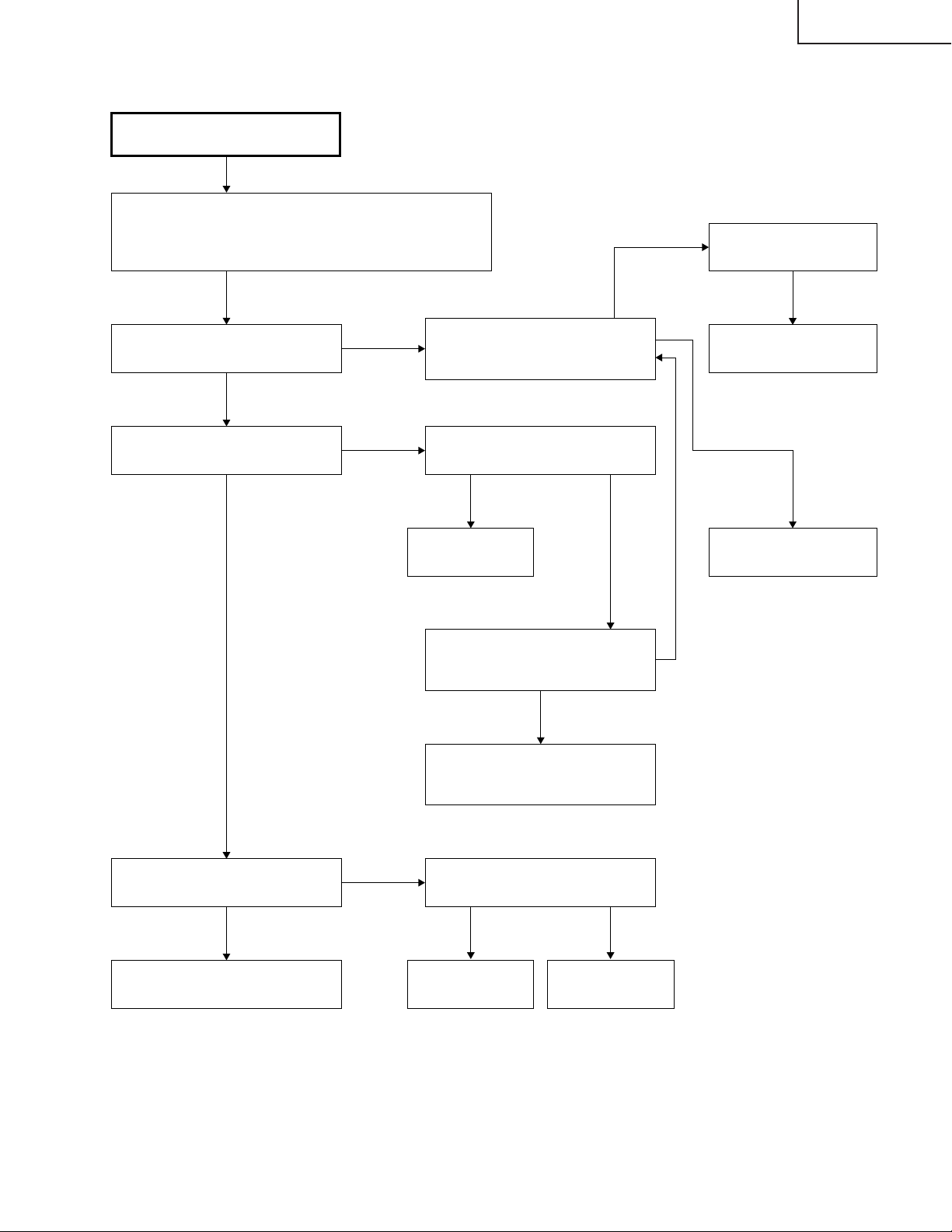
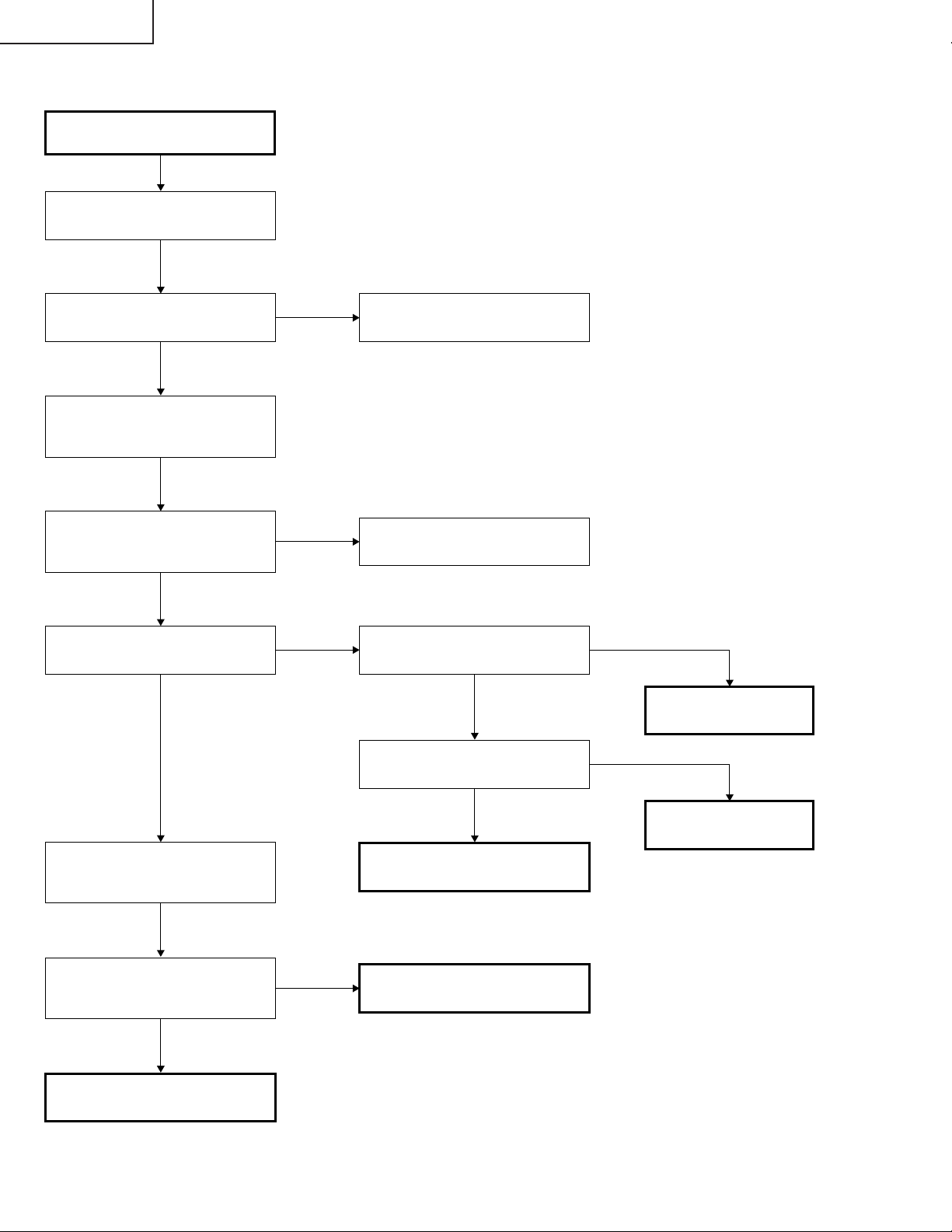
Page 31
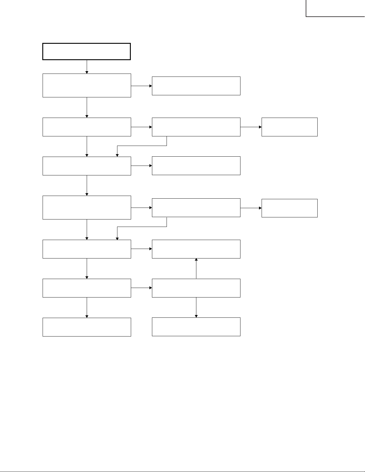
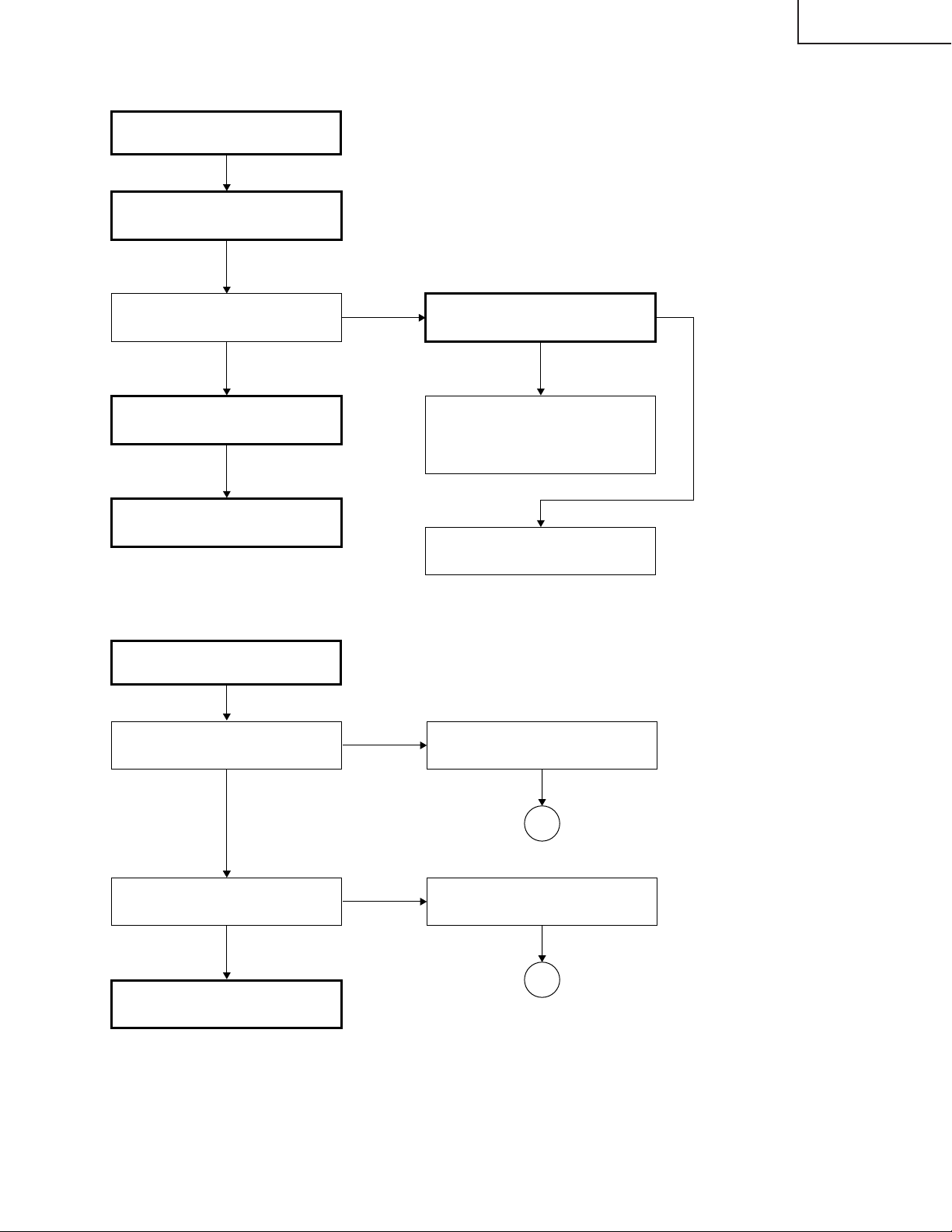
No
Lamp failure to light up
(formatter unit)
Yes
Is there the specified voltage at
pin (15) of SC9002?
No
Is there the 180-Hz pulse signal at
pin (1) of P9002?
Is any of the SC9001, SC9002,
P9002 and P9003 connectors
disconnected or in poor contact?
Yes
Insert the connectors completely.
No
Is there the specified voltage at
pin (11) of P3002?
No
Check the fan circuit
(near IC2101) on the
KEY PWB.
No
Check the power unit.
Are there the specified voltages
at pins (23) and (24) of P3003 on
the input PWB?
Go to "Checking of PC I/F unit"
Yes
Yes
Check the lamp and ballast unit.
Yes
Is the signal at pin (10) of IC9101
at High level?
No
Are the signals at pins (69) and
(70) of SC9001 at High level?
Yes
No
Yes
Is the signal at pin (9) of IC9101
at High level?
No
Trouble with IC9003.
Trouble with IC9101 or its
peripheral part.
Yes
Is there the 180-Hz pulse signal at
pin (2) of P9003 when no input
signal is given?
No
Yes
PG-M25X
31
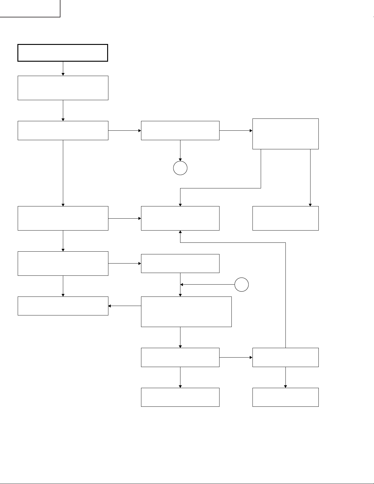
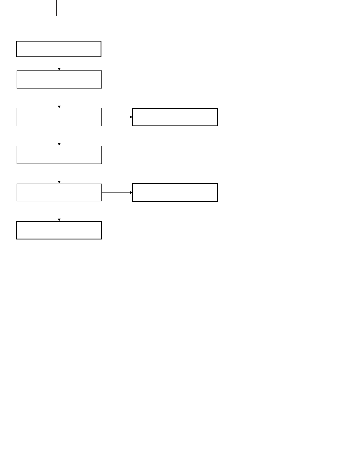
Page 32
PG-M25X
Lamp does not light up.
Yes
Is the cooling fan rotating?
Yes
Is the color wheel rotating sound
heard?
Yes
Is the lamp discharging sound
heard?
No
No
No
Yes
Check the power circuit or the fan
circuit on the key/input PWB.
Check IC3101, the motor driver
circuit and their periphery.
Check the waveform of SC3101.
Normal Abnormal
Replace the color
wheel.
Check the socket
Check the
formatter PWB.
No
Replace the lamp.
Is DC 340V voltage applied across
the ballast power?
Yes
Go to "Lamp failure to light up
(formatter unit)".
No
Check the power circuit.
32
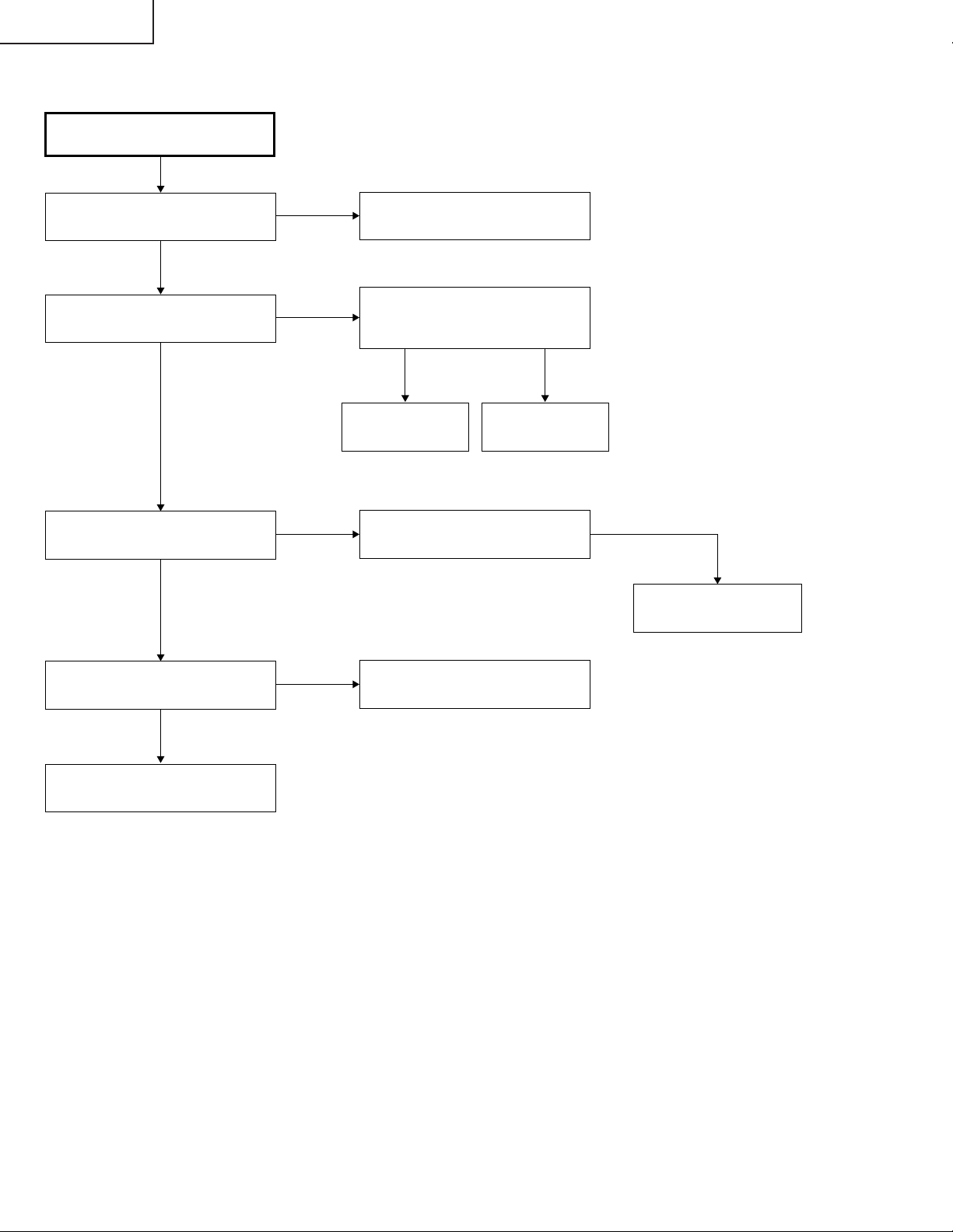
Page 33
No
Yes
Does POWER LED flicker in red
(for 2 seconds)?
No
Is there B+3.3V output at pins (12)
and (13) of CN3701?
Is there 6V output at pins (5) and
(6) of P2003?
Yes
Go to "Checking of PC I/F Unit", and check
the flexible connector.
Communication error of sub-microprocessor
(KEY) and SH microprocessor (PC I/F unit)
Pins (20) and (21) of P2001.
Yes
Go to "Checking of Power Unit"
Check Q2001 thru Q2004
and IC2001.
No
No
Yes
Is Bu+6.2V signal outputted?"
Go to "Checking of
Power Unit"
Yes
No
Is Bu+3.3V signal outputted?
Check IC2010 and its
periphery.
Check IC2010 and its
periphery.
Yes
No
Is 3.3V signal output at pin
(19) of IC2001?
Check IC2001 and its
periphery and go to
"Checking of Remote Control
Communication".
Checking of Sub-microprocessor
and Its Periphery
PG-M25X
33
Page 34
PG-M25X
Checking of Low-pass Filter Circuit
Is video signal is inputted to pins
(4), (8) and (12) of IC3851?
Yes
Is video signal inputted to pins
(24), (21) and (17) of IC3851?
Yes
Is video signal is inputted to pins
(16), (20) and (24) of IC3001?
Yes
The low-pass filter circuit on the
input PWB is normal. Does the
picture appear?
Yes
No
No
No
No
Check pins (4), (8) and (12) of
SC3001.
Normal Abnormal
Check Q3854 and
Q3855.
IC3851 is defective.
If the picture quality is abnormal, check whether
or not the following voltages are outputted to
pin (28) of IC3851.
0.3 V for 480i, 1 V for 720p, 1080i, Check IC301.
Check Q3851, Q3852 and Q3853
and their periphery.
Is the video signal inputted to pins
(8), (17) and (23) of IC8013
(AD9888) of the PC I/F unit?
Yes No
Check the PC I/F unit.
Check DVI (analog)
input.
End
Check the SOG
circuit or IC8013
and its periphery.
34
Check IC8013
and its periphery.
Page 35
Feed the 480i component signal in INPUT 1.
Select INPUT 1 using the set's key or the remote controller.
Select 480i among the special modes on the user
menu screen.
Is 480i selected among the special
modes?
Does the contour of picture
appear clear.
Confirmation of synchronization.
Is Y signal including sync signal
inputted to pin (3) of IC3502?
Is picture outputted?
Is the color normal?
No
Is the signal type set to the
component?
In case of monitor output,
disconnect the monitor output
cable.
Set the monitor output.
Check the monitor output
equipment and cable.
No
Yes
Yes
No
Yes
Yes No
Yes
Abnormal
No
Set the signal type.
IC8025 is defective. Select 480i.
Restored to normal condition
Yes
End
Checking of DTV
(480i Component Input)
Check IC8016
(Video decoder).
Go to "Checking of
Low-pass Filter Circuit"
Check IC3501 and its
periphery.
Yes
No
PG-M25X
35
Page 36
PG-M25X
Checking of Video Input
Feed the composite video signal to
INPUT 3. Select INPUT 3 using the
set's key or the remote controller.
Does the picture appear?
No No
Is the video signal including sync
signal inputted to pin (3) of SC3001
on the input PWB?
No
Is the video signal including sync
signal inputted to pin (7) of IC3501
on the input PWB?
No
Yes Yes
Yes
Yes
Is the picture disturbed?
1
Check IC8016 (video decoder)
of PC board and its periphery.
Check Q8002.
Check Q3512 and Q3513 on
the input PWB.
Are pin(5) (horizontal) and
pin(10) (vertical) signals
inputted to IC8363 on the
PC I/F unit?
No
Check IC8363 and
IC8025 (CVIC2) and
their periphery.
1
Yes
Check IC3501 and its peripheral
circuit.
No
Feed the S-video signal to INPUT 2.
Select INPUT 2 using the set's key
or the remote controller. Does the
picture appear?
Yes
Is the color normal?
Yes
End
No
36
Yes
Is the C signal inputted
to pin (11) of SC3001?
No
Check Q3502 on the
input PWB.
Page 37

» FORMATTER Unit
PG-M25X
Abnormal picture
Rainbow-like picture
Go to "Lamp Does Not
Light Up."
Is signal outputted at
pins (3), (5) and (7) of
SC9001?
Yes
Trouble with IC9003,
IC9006 or their periphery
Is any of SC9001, SC9002, P9002
and P9003 connectors
disconnected or in poor contact?
Is an appropriate voltage supplied
to SC9002?
No
No
Yes
Blackout
No
No Yes
Yes
No
Is the lamp on?
Go to "Checking of PC I/F unit"
Insert the connectors
completely.
Check the regulator ICs on the
input PWB and KEY PWB.
Others
Reassemble the DMD, optical
mechanism and formatter unit.
Is the symptom improved?
No
Is the voltage at the positive-polarity
pin of C9066 appropriate (+7V)?
Yes
Is the voltage at the positive-polarity
pin of C9068 appropriate (+23 to +26V)?
Yes
Is the voltage at the negative-polarity
pin of C9562 appropriate (-26V)?
Yes
Trouble with the DMD
Yes
No
No
No
End
Trouble with peripheral circuit
of C9066 or trouble with IC9003.
Trouble with peripheral circuit
of C9068 or trouble with IC9003.
Trouble with peripheral circuit
of C9562 or trouble with IC9003.
37
Page 38
PG-M25X
» PC I/F Unit-1/12
Checking of PC PWB
0
Is the user menu displayed?
No
Check the onscreen display.
Check the RGB input.
Check the component input.
Check the video input.
Yes
Check the DVI digital input.
PCカードのチェック
Check the PC card.
End
38
Page 39
» PC I/F Unit-2/12
Checking of Onscreen Display
PG-M25X
Is the user menu displayed
normally by the MENU key?
No
Enter the process menu and select
PATTERN. Then select the
COLOR pattern.
Is the onscreen display color
normal?
Yes
Make STEP signal selection.
Is the STEP signal normal?
Yes
No
Yes
The onscreen display is normal.
Adjust the DLP system in the
process adjustment mode.
0
Rewrite the onscreen display data.
No
Is the signal compatible with the
STEP signal outputted at TL106
thru TL111?
Yes
Go to "Checking of GA4 and Its
Periphery".
Rewrite the onscreen display data.
No
0
IC8025 is defective.
39
Page 40
PG-M25X
» PC I/F Unit-3/12
Checking of RGB Input
Feed the sync separation type
analog RGB signal to INPUT 1.
1
Select INPUT 1 using the set's
key or the remote controller.
2
Does the picture appear?
Is the picture disturbed?
3
Do the three colors R, G and B
appear?
Carry out the AUTOSYNC process.
Is the contour of picture clear?
Yes
No
Yes
No
Yes
No
No
Go to "Confirmation of
Video Input".
Go to "Checking of Sync Signal".
Go to "Checking of RGB Signal".
Yes
Is there any disturbance in the
vertical stripe pattern?
No
End
Yes
IC8013, 8025 or its periphery is
defective.
40
Page 41
» PC I/F Unit-4/12
Confirmation of Video Input
Make "Confirmation of Input
Signal Setting".
PG-M25X
Is there video signal at the land
of C8070?
Yes
Go to "Checking of Sync Signal".
IC8025 or IC8013 is defective.
Confirmation of Input Signal Setting
Is the input menu selected
correctly?
Yes
No
No
Is there signal at the terminal C2 of
P8001 (DVI connector)?
Yes
Somewhere in the signal route is
defective. Check the capacitors and
resistors between the connector
and IC8013.
The signal source or connector
is defective.
Select the input menu correctly.
No
Are the connectors connected
correctly?
Yes
End
No
2
Connect the connectors correctly.
1
41
Page 42
PG-M25X
» PC I/F Unit-5/12
Checking of Sync Signal
Is there the vertical sync signal at
pin (11) of IC8363?
Yes
Is there the horizontal sync signal
at pin (5) of IC8363?
Yes
Is there the vertical sync signal at
TL8131?
Yes
Is there the horizontal sync signal
at TL8130?
Yes
No
No
No
No
Make confirmation of input signal
setting.
IC8330, IC8331 or its periphery
is defective.
IC8363 is defective.
Are both the vertical and horizontal
signals in appropriate timing?
No
Is the signal generator
(input source) appropriate?
Yes
IC8330, IC8331 or its periphery
is defective.
Yes
No
The sync signal is normal.
End of checking.
Set the signal source appropriately.
2
42
Page 43
» PC I/F Unit-6/12
Checking of R, G and B Signals
PG-M25X
Is the signal type set to RGB?
Yes
Set the process mode.
Select R, G and B individually on
the pattern menu.
Go to "Checking of GA4 and Its
Periphery".
For checking the input signal,
set the signal generator to
gradation signal.
No
Set the signal type to RGB.
Check TL8169, TL8170 and
TL8180 by oscilloscope.
(MSB bit after A/D conversion)
Are there the specified signals at
TL8169, TL8170 and TL8180?
Yes
IC8025 and its periphery are
defective.
No
Does the signal come to C8062,
C8070 and C8078?
Yes
IC8013 and its periphery are
defective.
No
Go to "Confirmation of
Video Input".
43
Page 44
PG-M25X
» PC I/F Unit-7/12
Checking of GA4 and Its Periphery
Select R, G and B individually on
the pattern menu in process mode.
Is picture outputted appropriately
in R, G and B?
No
Check pins (72), (52) and (32) of
SC8001 by oscilloscope.
These signals are MSB of B/G/R.
Do the signals selected on the
pattern menu match with those
checked by oscilloscope?
No
Does the clock signal come to pin
(78) of SC8001?
Yes
Yes
Yes
No
Checking of GA4 and its periphery
ends.
The DLP PWB is defective.
Is there the clock (32.5 MHz)
signal at TL8114?
No
Is there the clock (32.5 MHz)
signal at TL8110?
Yes
Yes
IC8029 is defective.
No
X8005 is defective.
Check TL8106, TL8107, TL8108,
TL8109, TL81010 and TL81011
by oscilloscope.
Do the signals selected on the
pattern menu match with those
checked by oscilloscope?
Yes
IC8029 is defective.
IC8025 is defective.
No
IC8025 is defective.
44
Page 45

» PC I/F Unit-8/12
Checking of Component Input
Feed the component signal to
INPUT 1.
Select INPUT 1 using the set's
key or the remote controller.
PG-M25X
(except 480I)
Is the picture appear?
Yes
4
Is the color normal?
No
Is the signal type set at component?
Yes
Carry out the process adjustment.
4
No
No
Go to "Checking of SOG Circuit".
Set the signal type to component.
Is the contour of picture clear?
Yes
The component is normal. End.
No
IC8013 or IC8025 is defective.
45
Page 46
PG-M25X
» PC I/F Unit-9/12
Checking of SOG Circuit
Check pin (2) of IC8365 by
oscilloscope.
Is the composite sync signal
reproduced in correct timing?
No
Check the land of C8070 by
oscilloscope.
Is there the Y signal including sync
signal?
Yes
The SOG sync separation circuit
(input PWB) is defective.
Yes
No
The SOG circuit is normal.
End.
Go to "Confirmation of Input
Signal Setting".
46
Page 47

PG-M25X
Feed the composite video signal to
INPUT 3.
Select INPUT 3 using the set's key
or the remote controller.
Is there any disturbance in the
picture?
The video input is normal. End.
Is the color normal?
Is the picture appear?
Go to "Checking of Video
Sync Signal".
No
Yes
Input PWB is defective.
Q8002 and its periphery are
defective.
IC8015 is defective.
No
Is there the specified signal
at R8114?
No
5
5
No
Checking of Video Input
Go to "Checking of Video
Sync Signal".
Carry out the process
adjustment.
Yes
No
Yes
Check the clock signal of IC8015
by FL8114.
Is the clock signal normal?
Yes
IC8025 and its periphery are
defective.
Yes
Yes
Is the video signal inputted to
C8141?
No
Go to "Checking of Video Sync
Signal".
» PC I/F Unit-10/12
47
Page 48
PG-M25X
» PC I/F Unit-11/12
Checking of Video Sync Signal
Check pin (10) of IC8363 by
oscilloscope.
(Checking of vertical sync signal)
Is the vertical sync signal normal?
Yes
Check pin (6) of IC8363 by
oscilloscope.
(Checking of horizontal sync signal)
Is the horizontal sync signal
normal?
Yes
Are the horizontal sync signal and
vertical sync signal outputted at
TL8130 and TL8131?
Yes
Is there the specified clock
(13.5 MHz) signal at FL8114?
Yes
No
No
No
No
Go to "Confirmation of Input Signal
Setting".
IC8015 and its periphery are
defective.
IC8015 and its periphery are
defective.
End
48
Page 49
» PC I/F Unit-12/12
Checking of DVI Digital Input
Feed the DVI digital signal to
INPUT 1.
Select INPUT 1 for input.
PG-M25X
Is the picture appear?
Yes
Is there any disturbance in the
picture?
Yes
Is the color normal?
Yes
The DVI digital input is normal.
Check pin (13) of IC8363 for vertical
sync signal, and check pin (3) of
IC8363 for horizontal sync signal.
No
No
No
IC8298 and its periphery are
defective.
Are the sync signals normal?
Yes
Check R8685 for clock signal.
Is the clock signal normal?
Yes
IC8025 and its periphery are
defective.
No
No
IC8298 and its periphery are
defective.
49
Page 50

PG-M25X
Technische Daten
Produkttyp
Videosystem
Wiedergabeverfahren
DMD-Panel
Objektiv
Projektionslampe
Komponenten-Eingangssignale
(INPUT 1)
Horizontale Auflösung
Computer-RGB-Eingangssignal
(INPUT 1)
S-Videoeingangssignal
(INPUT 2)
Videoeingangssignal
(INPUT 3)
Pixeltakt
Vertikale Frequenz
Horizontale Frequenz
Audioeingangssignal
PC-Kartensteckplatz (INPUT 4)
Audioausgang
Lautsprechersystem
Nennspannung
Eingangsspannung
Nennfrequenz
Leistungsaufnahme
Wärmeableitung
Betriebstemperatur
Lagertemperatur
Gehäuse
Radiofrequenzbereich der
GyroRemote-Fernbedienung:
Abmessungen (ca.)
Gewicht (ca.)
Mitgeliefertes Zubehör
Ersatzteile
Digitaler Multimedia-Projektor
PG-M25X
Modell
NTSC 3.58/NTSC 4.43/PAL/PAL-M/PAL-N/PAL 60/SECAM/
/DTV480P/DTV720P/DTV1080
DTV480
Single Chip Digital Micromirror Device™ (DMD™) von Texas Instruments
Panel-Größe: 0,7
Anzahl der Bildpunkte: 786.432 Bildpunkte (1.024 [H] × 768 [V])
1–1.2 × Zoom-Objektiv, F1,75–2,04, f = 28,0–33,5 mm
Hochleistungslampe (HID-Lampe), DC 210 W
29-pol. Anschluss
DVI-Eingangssignal: Digital 250–1.000 mV 50 W
Y: 1,0 Vs-s, negatives Sync., 75 W terminiert
PB: 0,7 Vs-s, 75 W terminiert
PR: 0,7 Vs-s, 75 W terminiert
700 Fernsehzeilen (DTV720P)
29-pol. Anschluss
RGB getrennt/Sync auf Grün-Typ analoger Eingang: 0–0,7 Vs-s, positiv, 75 W terminiert
HORIZONTALES SYNC.-SIGNAL: TTL-Pegel (positiv/negativ)
VERTIKALES SYNC.-SIGNAL: Wie oben
4-pol. Mini DIN-Anschluss
Y (Luminanzsignal): 1,0 Vs-s, negatives Sync., 75 W terminiert
C (Chrominanzsignal): Stoß 0,286 Vs-s, 75 W terminiert
RCA-Anschluss: VIDEO, gemischtes Video, 1,0 Vs-s, negatives Sync.,
75 W terminiert
12–230 MHz
43–200 Hz*
15–126 kHz
ø 3,5 mm Minibuchse: AUDIO, 0,5 Vrms, mehr als 47 kW (Stereo)
PCMCIA-Typ
2,0 W (Mono)
4 cm × 3 cm
100-240 V Wechselstromspannung
3,2 A
50/60 Hz
295 W
1.110 kWh
41°F bis 95°F (+5°C bis +35°C)
–4°F bis 140°F (–20°C bis +60°C)
Plastik
49,825 bis 49,895 MHz (für USA, Kanada usw.), 40,667 bis 40,695 MHz
(für Europa, Ozeanien, Asien)
5
⁄8" × 3" × 11 15⁄16" (219 (B) × 76 (H) × 303 (T) mm) (nur Hauptgerät)
8
3
⁄4" × 3 1⁄4" × 12 1⁄2" (223 (B) × 83 (H) × 318 (T) mm) (einschließlich Drehfüße und Projektionsteile)
8
5,8 lbs. (2,6 kg)
GyroRemote-Fernbedienung, vier R-03-Batterien, Netzkabel (6', 1,8 m), zwei drahtlose LAN-PC-Karten,
DVI an 15-Pin D-Sub-Kabel (6', 1,8 m), USB-Kabel (6', 1,8 m), Tragetasche, Objektivkappe (befestigt),
Riemen für Objektivkappe, Anschlussabdeckung (befestigt), CD-ROM, Bedienungsanleitung für den
Projektor, Kurzanleitungen, Bedienungsanleitung für Wireless Reality-Software, Bedienungsanleitung
für die drahtlose LAN PC-Karte.
Lampeneinheit (Lampen-/Gehäusemodul) (BQC-PGM20X//1) GyroRemote-Fernbedienung für USA,
Kanada usw., (RRMCG1631CESA), GyroRemote-Fernbedienung für Europa, Australien, Ozeanien
und Asien (RRMCG1653CESA), Vier R-03-Batterien (“AAA”-Größe, UM/SUM-4, HP-16 oder
entsprechend), Netzkabel für USA, Kanada usw. (QACCDA007WJPZ), Netzkabel für Europa, außer
Großbritannien (QACCV4002CEZZ), Netzkabel für Großbritannien und Hongkong (QACCB5024CENA),
Netzkabel für Australien, Neuseeland und Ozeanien (QACCL3022CEZZ), DVI an 15-Pin D-Sub-Kabel
(QCNWGA010WJZZ), USB-Kabel (QCNWG0001WJPZ), drahtlose LAN PC-Kar ten AN-WC11B
(RUNTKA025WJZZ), Tragetasche (GCASN0005CESA), Objektivkappe (CCAPHA001WJ01), Riemen
für Objektivkappe (UBNDT0013CEZZ), Anschlussabdeckung (GCOVD0103CESA), CD-ROM
(UDSKAA001WJZZ), Bedienungsanleitung für den Projektor (TINS-A046WJZZ), Kurzanleitungen,
Bedienungsanleitung für Wireless Reality-Software (TINS-A049WJZZ), Bedienungsanleitung für die
drahtlose LAN PC-Karte (TINS-A306WJZZ).
"
(17,8 mm), 1 Chip XGA DMD
Analog 0,7 Vs-s 75 W
* Bei vertikalen Frequenzen über 100 Hz kann eine zeitweise Störung sichtbar werden, wenn die OSD-
Funktionen eingeschaltet sind.
Dieser Projektor von SHARP ist mit einem DMD-Panel
ausgestattet. Diese neuartigen Panel enthalten 786.432
Bildpunkte. Bei allen technologisch fortschrittlichen, elektronischen
Geräten, z. B. Großbild-Fernsehern, Videosystemen bzw.
Videokameras, sind bestimmte T oleranzgrenz en für die Funktionen
gegeben.
Änderungen der technischen Daten ohne vorherige Ankündigung vorbehalten.
Dieses Gerät hat einige inaktive, innerhalb akzeptierter
Toleranzgrenzen liegende Bildpunkte, die als leuchtende oder als
nicht aktive Punkte auf der Bildwand wiedergegeben werden. Dies
hat keinen Einfluss auf die Bildqualität oder die Lebensdauer des
Gerätes.
50
Page 51
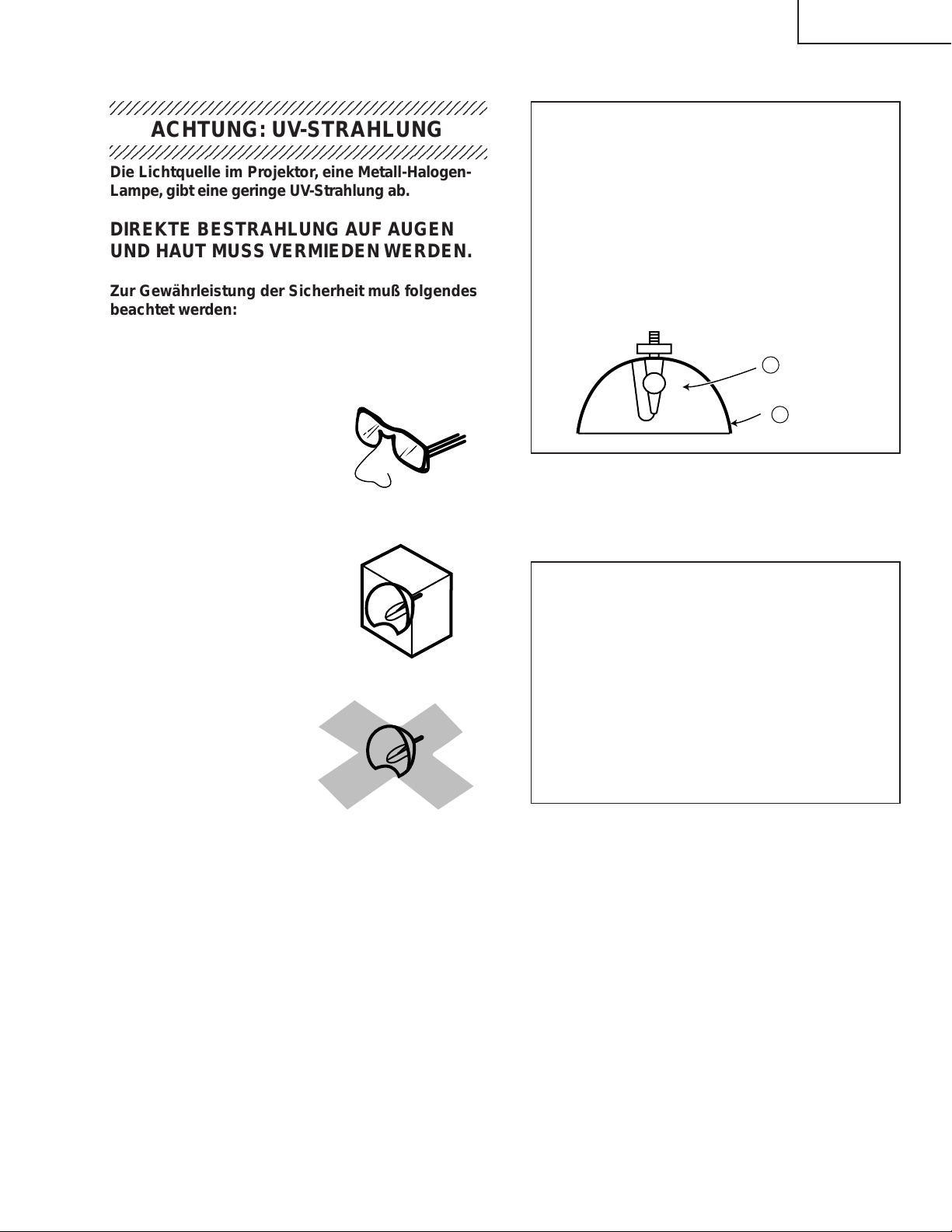
HINWEIS FÜR DAS WARTUNGSPERSONAL
5
PG-M25X
ACHTUNG: UV-STRAHLUNG
234567890123456789012345678901212345678901234
Die Lichtquelle im Projektor, eine Metall-HalogenLampe, gibt eine geringe UV-Strahlung ab.
DIREKTE BESTRAHLUNG AUF AUGEN
UND HAUT MUSS VERMIEDEN WERDEN.
Zur Gewährleistung der Sicherheit muß folgendes
beachtet werden:
1. Bei Arbeiten am Projektor bei eingeschalteter
Lampe und abgenommenem oberen Gehäuse
muß unbedingt eine Sonnenbrille getragen
werden.
2. Die Lampe darf nicht außerhalb des
Lampengehäuses eingeschaltet werden.
Ë Auswechseln der Lampe
Hinweis:
Da die Lampe während des Betriebs sehr heiß wird,
sollte die Lampe erst ausgewechselt werden, nachdem
das Gerät mindestens eine Stunde ausgeschaltet war ,
damit die Lampe ausreichend abkühlen kann.
Beim Installieren der neuen Lampe muß darauf
geachtet werden, die Lampe selbst (Glaskolben)
nicht zu berühren. Vielmehr muß die Lampe am
Reflektor 2 gehalten werden.
[Es darf nur ein Original-Ersatzteil verwendet
werden.]
Lampe
1
2
Reflektor
GEFAHR! — Niemals die Spannungsversorgung
einschalten, ohne daß eine Lampe vorhanden ist,
um elektrische Schläge und Schäden am Gerät zu
vermeiden, da der Stabilisator anfangs hohe
Spannungen erzeugt.
3. Betrieb für länger als 2 Stunden bei
abgenommenem Gehäuse ist nicht zulässig.
Zur Beachtung bei UV-Strahlung
und Mitteldruck-Lampen
1. Vor dem Auswechseln der Lampe muß der
Netzstecker gezogen werden.
2. Vor Durchführung von Wartungsarbeiten muß das
Gerät eine Stunde abkühlen.
3. Nur mit dem gleichen Lampentyp ersetzen Typ
BQC-PGM20X//1; Nennleistung 85 V/210 W.
4. Die Lampe gibt eine geringe UV-Strahlung ab,
daher muß direkter Augenkontakt vermieden
werden.
5. Die Mitteldruck-Lampe weist ein Explosionsrisiko
auf. Daher müssen die nachstehenden
Installationsanweisungen beachtet werden, und die
Lampe muß vorsichtig behandelt werden.
Da eine geringe UV-Strahlung aus einer Öffnung
zwischen der Schachtabdeckung und dem
Lampengehäuse austritt, sollte der Objektivdeckel
bei Wartungsarbeiten auf die Öffnung gesetzt
werden, um die Bestrahlung von Augen und Haut
zu vermeiden.
Hinweis: Besorgen Sie sich einen Objektivdeckel,
bevor Sie Arbeiten an einem Modelle PGM20X durchführen, das keinen
Objektivdeckel aufweist.
51
Page 52
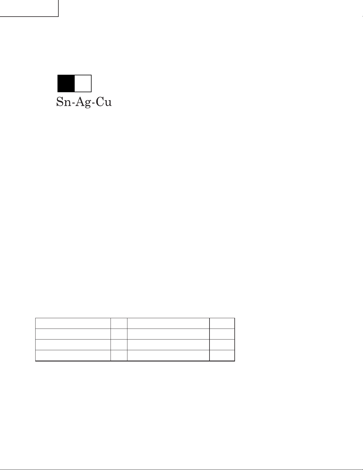
PG-M25X
Vorsichtsmaßregeln für bleifreien Lötzinn
1 Verwendung von bleifreiem Lötzinn
Die "Eingangs-, Betriebs-, Gyro-und Gyro-Hilfs-Platine" dieses Modells verwendet bleifreien Lötzinn. Das LF-Symbol zeigt bleifreien Lötzinn an und ist an den Platinen und Wartungsanleitungen angebracht. Der Buchstabe nach
LF zeigt den Typ des bleifreien Lötzinns an.
Beispiel:
L Fa
Zeigt bleifreien Lötzinn aus Zinn, Silber und Kupfer an.
2 Bei Reparatur der mit bleifreiem Lötzinn gelöteten Platine immer bleifreien Lötzinn verwenden. Reparatur mit
herkömmlichem Lötzinn kann zu Schäden oder Unfällen aufgrund von Rissen führen.
Da der Schmelzpunkt bleifreien Lvtzinns (Sn-Ag-Cu) um 40°C höher als der von Bleidraht-Lötzinn ist, empfehlen wir
die Verwendung einer speziellen Lötspitze. W enn F ragen über den Beschaffung leitfreien Lötzinns oder spezieller
Lötspitzen bestehen, wenden Sie sich an unsere Kundendienstvertretung in Ihrem Gebiet.
3Löten
Da der Schmelzpunkt bleifreien Lötzinns (Sn-Ag-Cu) etwa 220°C beträgt, w as um 40°C höher als der v on bleihaltigem
Lötzinn ist, und außerdem schlechte Löt-Benetzbarkeit aufweist, kann es erforderlich werden, die Lötspitze längere
Zeit in Kontakt mit der Platine zu halten. Da die Lötlauge abfliessen kann oder der maximale Hitzewiderstand von
Teilen überschritten werden kann, die Lötspitze sofort von der Platine nehmen, sobald eine gute Lötung erzielt ist.
Bleifreier Lötzinn enth_lt mehr Zinn, und das Ende der Lötspitze kann leicht angegriffen werden. Immer sicherstellen,
dass der Lötkolben nur bei Bedarf eingeschaltet wird.
Wenn ein anderer Typ von Lötzinn an der Lötspitze haften bleibt, verschmilzt er mit dem bleifreien Lötzinn. Die
Lötspitze nach jeder Verwendung reinigen.
Wenn die Lötspitze bei der Verwendung geschwärzt wird, die Spitze mit Stahlwolle oder feinem Sandpapier
abschmirgeln.
Immer beim Austausch von T eilen v orsichtig sein, und die Polaritätsanzeige auf der Platinenbeschriftung beachten.
Bleifreier Lötzinn zur Wartung
Teile-Nr. ★ Beschreibung Code
ZHNDAi123250E J φ0.3mm 250g(1roll) BL
ZHNDAi126500E J φ0.6mm 500g(1roll) BK
ZHNDAi12801KE J φ1.0mm 1 Rolle BM
52
Page 53
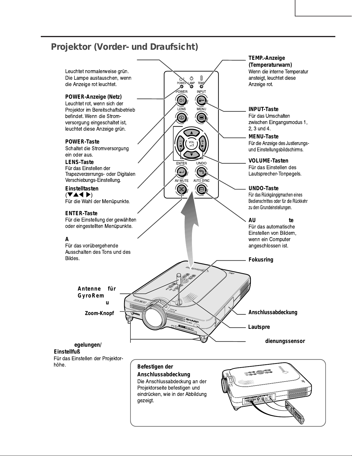
Bedienelemente
Projektor (Vorder- und Draufsicht)
PG-M25X
LAMP-Anzeige
(Lampenaustausch)
Leuchtet normalerweise grn.
Die Lampe austauschen, wenn
die Anzeige rot leuchtet.
POWER-Anzeige (Netz)
Leuchtet rot, wenn sich der
Projektor im Bereitschaftsbetrieb
befindet. Wenn die Strom-
versorgung eingeschaltet ist,
leuchtet diese Anzeige grn.
POWER-Taste
Schaltet die Stromversorgung
ein oder aus.
LENS-Taste
Fr das Einstellen der
Trapezverzerrungs- oder Digitalen
Verschiebungs-Einstellung.
Einstelltasten
(
"'\ |
Fr die Wahl der Menpunkte.
)
ENTER-Taste
Fr die Einstellung der gewhlten
oder eingestellten Menpunkte.
AV MUTE-Taste
Fr das vorbergehende
Ausschalten des Tons und des
Bildes.
TEMP.-Anzeige
(Temperaturwarn)
Wenn die interne Temperatur
ansteigt, leuchtet diese
Anzeige rot.
INPUT-Taste
Fr das Umschalten
zwischen Eingangsmodus 1,
2, 3 und 4.
MENU-Taste
Fr die Anzeige des Justierungs-
und Einstellungsbildschirms.
VOLUME-Tasten
Fr das Einstellen des
Lautsprecher-Tonpegels.
UNDO-Taste
Fr das Rckgngigmachen eines
Bedienschrittes oder fr die Rckkehr
zu den Grundeinstellungen.
AUTO SYNC-Taste
Fr das automatische
Einstellen von Bildern,
wenn ein Computer
angeschlossen ist.
Fokusring
Antenne für
GyroRemoteFernbedienung
Zoom-Knopf
Fußentriegelungen/
Einstellfuß
Fr das Einstellen der Projektor-
hhe.
Anschlussabdeckung
Lautsprecher
Fernbedienungssensor
Befestigen der
Anschlussabdeckung
Die Anschlussabdeckung an der
Projektorseite befestigen und
eindrcken, wie in der Abbildung
gezeigt.
53
Page 54
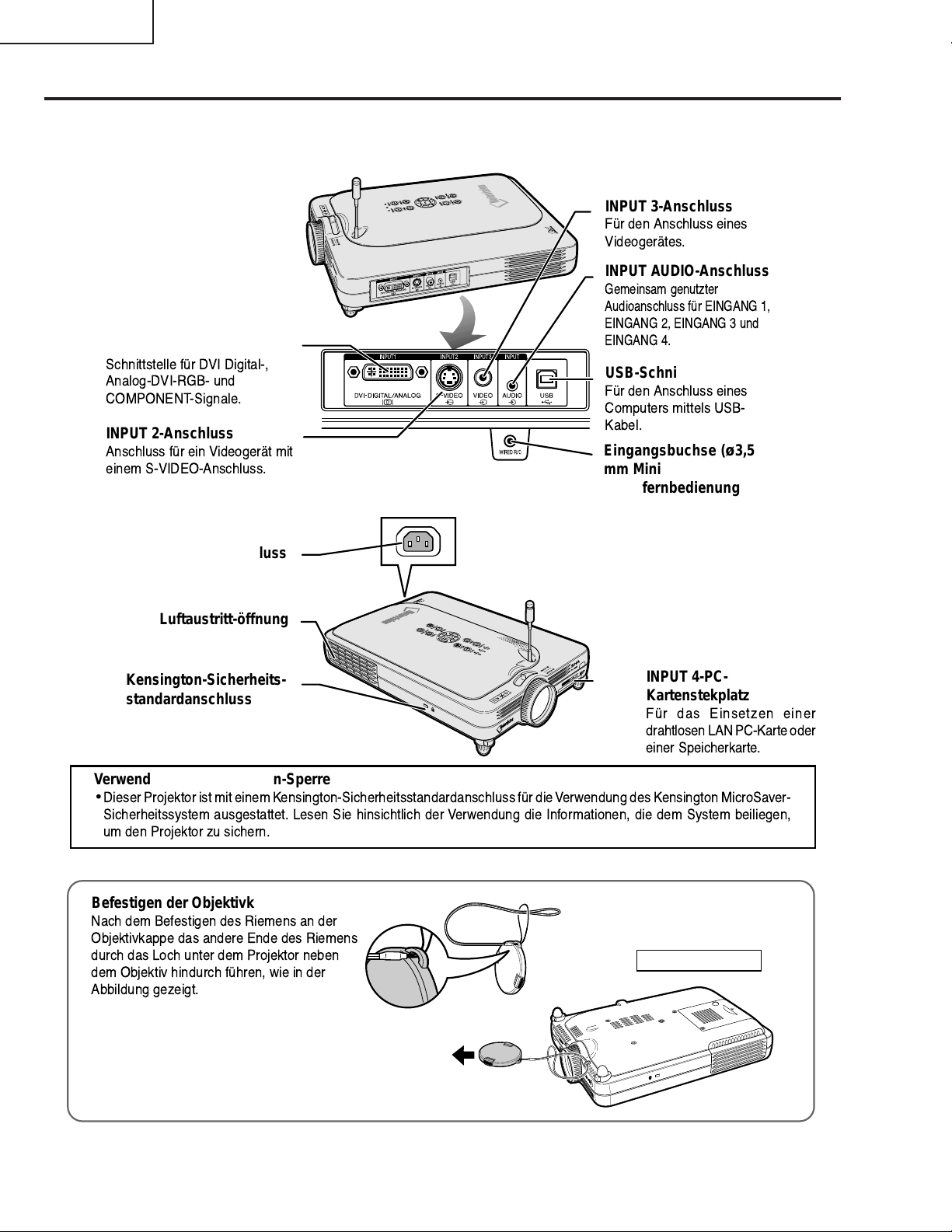
PG-M25X
Projektor (Seitenansicht)
INPUT 1-Anschluss
Schnittstelle fr DVI Digital-,
Analog-DVI-RGB- und
COMPONENT-Signale.
INPUT 2-Anschluss
Anschluss fr ein Videogert mit
einem S-VIDEO-Anschluss.
INPUT 3-Anschluss
Fr den Anschluss eines
Videogertes.
INPUT AUDIO-Anschluss
Gemeinsam genutzter
Audioanschluss fr EINGANG 1,
EINGANG 2, EINGANG 3 und
EINGANG 4.
USB-Schnittstelle
Fr den Anschluss eines
Computers mittels USB-
Kabel.
Eingangsbuchse (ø3,5
mm Mini-Buchse) für
Kabelfernbedienung
Netzanschluss
Luftaustritt-öffnung
Kensington-Sicherheitsstandardanschluss
INPUT 4-PCKartenstekplatz
Fr das Einsetzen einer
drahtlosen LAN PC-Karte oder
einer Speicherkarte.
Verwendung der Kensington-Sperre
•
Dieser Projektor ist mit einem Kensington-Sicherheitsstandardanschluss fr die Verwendungdes Kensington MicroSaver-
Sicherheitssystem ausgestattet. Lesen Sie hinsichtlich der Verwendung die Informationen, die dem System beiliegen,
um den Projektor zu sichern.
Befestigen der Objektivkappe
Nach dem Befestigen des Riemens an der
Objektivkappe das andere Ende des Riemens
durch das Loch unter dem Projektor neben
dem Objektiv hindurch fhren, wie in der
Abbildung gezeigt.
Ansicht von unten
54
Page 55
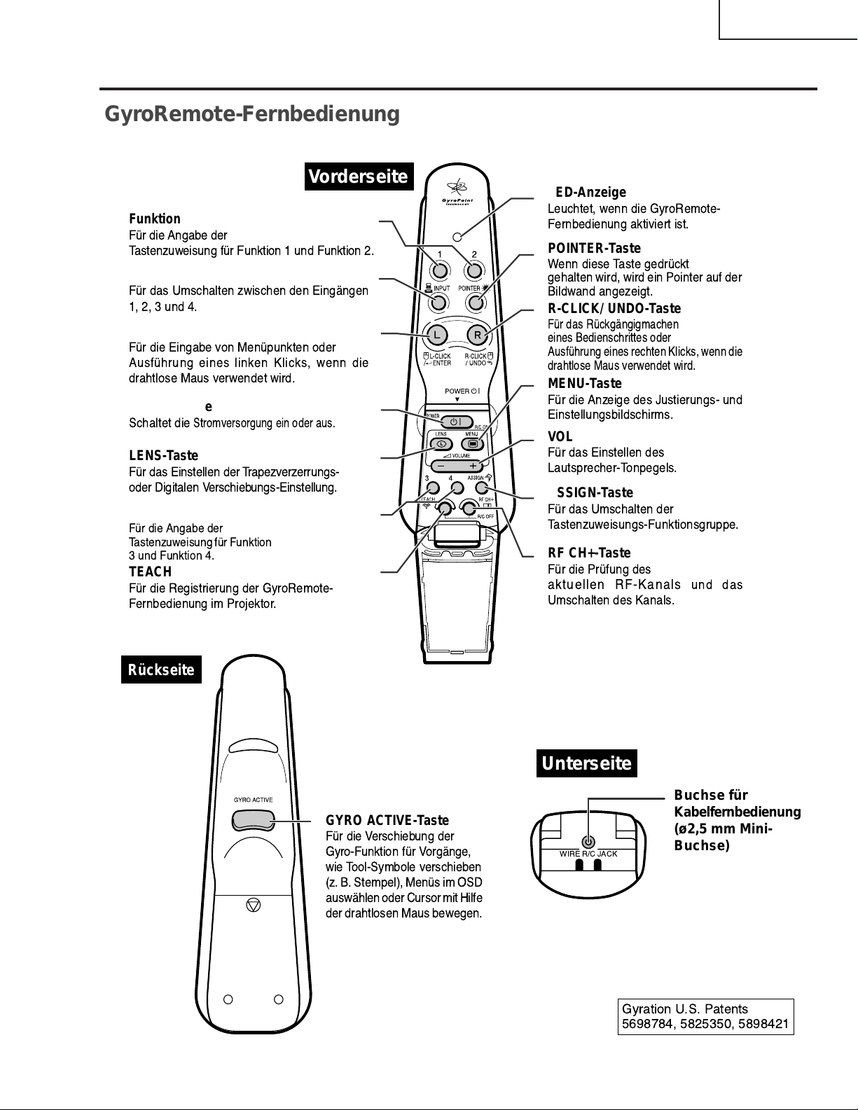
GyroRemote-Fernbedienung
Vorderseite
Funktionstasten 1 / 2
Fr die Angabe der
Tastenzuweisung fr Funktion 1 und Funktion 2.
INPUT-Taste
Fr das Umschalten zwischen den Eingngen
1, 2, 3 und 4.
L-CLICK/ ENTER-Taste
Fr die Eingabe von Menpunkten oder
Ausfhrung eines linken Klicks, wenn die
drahtlose Maus verwendet wird.
POWER-Taste
Schaltet die
LENS-Taste
Fr das Einstellen der T rapezv erz errungs-
oder Digitalen V erschieb ungs-Einstellung.
Funktionstasten 3 / 4
Fr die Angabe der
Tastenzuweisung fr Funktion
3 und Funktion 4.
TEACH (OK)-Taste
Fr die Registrierung der GyroRemote-
Fernbedienung im Projektor.
Stromversorgung ein oder aus.
PG-M25X
LED-Anzeige
Leuchtet, wenn die GyroRemote-
Fernbedienung aktiviert ist.
POINTER-Taste
Wenn diese Taste gedrckt
gehalten wird, wird ein Pointer auf der
Bildwand angezeigt.
R-CLICK/ UNDO-Taste
Fr das Rckgngigmachen
eines Bedienschrittes oder
Ausfhrung eines rechten Klicks, wenn die
drahtlose Maus verwendet wird.
MENU-Taste
Fr die Anzeige des Justierungs- und
Einstellungsbildschirms.
VOLUME-Tasten
Fr das Einstellen des
Lautsprecher-Tonpegels.
ASSIGN-Taste
Fr das Umschalten der
Tastenzuweisungs-Funktionsgruppe.
RF CH+-Taste
Fr die Prfung des
aktuellen RF-Kanals und das
Umschalten des Kanals.
Rückseite
GYRO ACTIVE-Taste
Fr die V erschiebung der
Gyro-Funktion fr Vorgnge,
wie Tool-Symbole verschieben
(z. B. Stempel), Mens im OSD
auswhlen oder Cursor mit Hilfe
der drahtlosen Maus bewegen.
Unterseite
WIRE R/C JACK
Buchse für
Kabelfernbedienung
(ø2,5 mm MiniBuchse)
Gyration U.S. Patents
5698784, 5825350, 5898421
55
Page 56
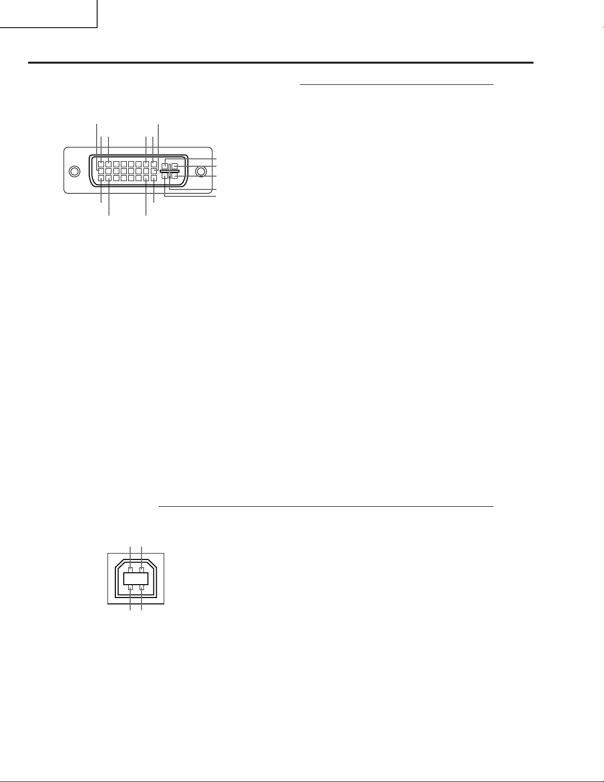
PG-M25X
Pin-Belegung
DVI Digital-/Analog-EINGANG 1-Port: 29 Pin-Anschluss
•••••••••
~
9
••••
~
21
17
••••
~
18 23
•
DVI-Analog-RGB-Eingang
Pin-Nr. Signal Pin-Nr. Signal
1 Nicht angeschlossen 16 Hot Plug festgestellt
2 Nicht angeschlossen 17 Nicht angeschlossen
3 Nicht angeschlossen 18 Nicht angeschlossen
4 Nicht angeschlossen 19 Nicht angeschlossen
5 Nicht angeschlossen 20 Nicht angeschlossen
6 DDC-Taktgeber 21 Nicht angeschlossen
7 DDC-Daten 22 Nicht angeschlossen
8 Vertikales Sync. 23 Nicht angeschlossen
9 Nicht angeschlossen 24 Nicht angeschlossen
10 Nicht angeschlossen C1 Analogeingang Rot
11 Nicht angeschlossen C2 Analogeingang Grün
12 Nicht angeschlossen C3 Analogeingang Blau
13 Nicht angeschlossen C4 Horizontales Sync.
14 +5V-Stromversorgung C5 Masse
15 Masse
•••••••••
••••
••••
•
DVI-Digital-EINGANG
16
87
C1
C2
C4
C5
C3
24
Pin-Nr. Signal Pin-Nr. Signal
1 T.M.D.S-Daten 2– 16 Hot Plug festgestellt
2 T.M.D.S-Daten 2+ 17 T.M.D.S-Daten 0–
3 T.M.D.S-Daten 2 Abschirmung 18 T.M.D.S-Daten 0+
4 Nicht angeschlossen 19 T.M.D.S-Daten 0 Abschirmung
5 Nicht angeschlossen 20 Nicht angeschlossen
6 DDC-Taktgeber 21 Nicht angeschlossen
7 DDC-Daten 22
8 Nicht angeschlossen 23 T.M.D.S-Taktgeber+
9 T.M.D.S-Daten 1– 24 T.M.D.S-Taktgeber–
10 T.M.D.S-Daten 1+ C1 Nicht angeschlossen
11 T.M.D.S-Daten 1 Abschirmung C2 Nicht angeschlossen
12 Nicht angeschlossen C3 Nicht angeschlossen
13 Nicht angeschlossen C4 Nicht angeschlossen
14 +5V-Stromversorgung C5 Masse
15 Masse
•
DVI-Analog-Komponenten-Eingang
Pin-Nr. Signal Pin-Nr. Signal
1 Nicht angeschlossen 16 Nicht angeschlossen
2 Nicht angeschlossen 17 Nicht angeschlossen
3 Nicht angeschlossen 18 Nicht angeschlossen
4 Nicht angeschlossen 19 Nicht angeschlossen
5 Nicht angeschlossen 20 Nicht angeschlossen
6 Nicht angeschlossen 21 Nicht angeschlossen
7 Nicht angeschlossen 22 Nicht angeschlossen
8 Nicht angeschlossen 23 Nicht angeschlossen
9 Nicht angeschlossen 24 Nicht angeschlossen
10 Nicht angeschlossen C1 Analogeingang Pr/Cr
11 Nicht angeschlossen C2 Analogeingang Y
12 Nicht angeschlossen C3 Analogeingang Pb/Cb
13 Nicht angeschlossen C4 Nicht angeschlossen
14 Nicht angeschlossen C5 Masse
15 Masse
T .M.D.S-T aktgeber Abschirmung
4-Pin-USB-Anschluss
12
43
•
USB-Anschluss: 4 Pin B-Typ USB-Anschluss
Pin Nr. Signal Bezeichnung
1 VCC USB-Strom
2 USB– USB-Daten–
3 USB+ USB-Daten+
4 SG Signal-Masse
56
Page 57

Abmessungen
Einheiten: Zoll (mm)
Ansicht von
hinten
PG-M25X
Ansicht von
der Seite
¿54
Ansicht von
vorne
1
12
(306,5)
3
/
1
(34,2)
Ansicht von
oben
3
8
/4 (223)
/
16
1113/
(303)
5
/8 (219)
8
1
/16 (128)
5
8
11
/16 (195)
/4 (82,5)
9
/16 (115,5)
4
3
/
2
(55,5)
¿54
7
1
3
16
3
/8 (60)
2
1
1
/2 (37,5)
27
(68,7)
1
1
(38,7)
1
/
2
16
/
16
(76)
Ansicht von
der Seite
1
3
3
/
(82,9)
15
5
/
16
(151,6)
4
(wenn die Antenne
herausgezogen ist)
Ansicht von
unten
3
(80)
1
/
8
5
/
16
(7,5)
1
4
/
8
(104)
5
/
10
(261,5)
16
57
Page 58
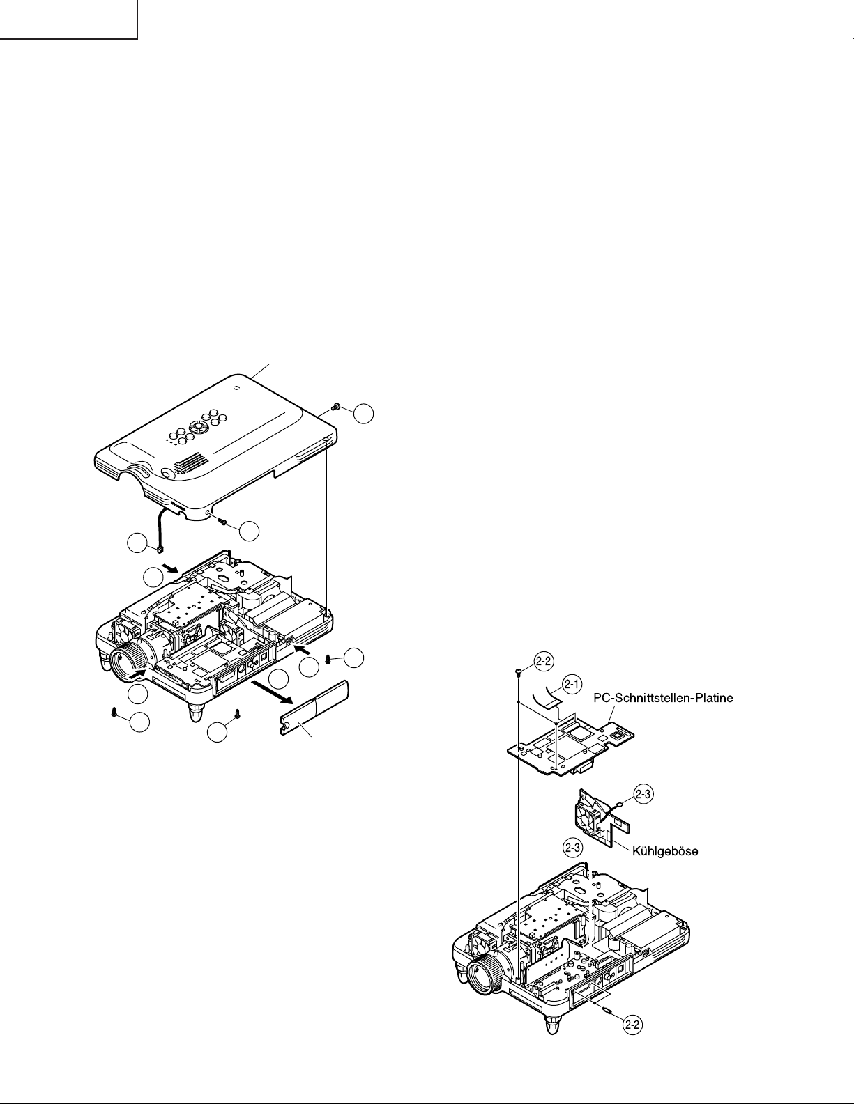
PG-M25X
A USBA U WICHTIGER TEILE
1. Ausbau der Oberabdeckung
1-1. Die Klemmenblock-Abdeckung entfernen.
1-2. Die fünf Sperrschrauben von der Oberabdeckung entfernen.
1-3. Die rechte Seite des Unterteils drücken, um den Haken zu lösen.
1-4. Die linke Seite des Unterteils drücken, um den Haken zu lösen.
1-5. Die vordere Seite des Unterteils drücken, um den Haken zu lösen. Die Oberplatte vom Unterteil lösen.
1-6. Leicht die Vorderseite der Oberplatte anheben, und den Lautsprecher-Steckverbinder abtrennen.
2. Ausbau der PC-Schnittstellen-Platine und des Kühlgeblöses
2-1. Den Steckverbinder abtrennen.
2-2. Die drei Sperrschrauben von der PC-Schnittstellen-Platine entfernen, und dann die beiden Sechskant-
Halteschrauben entfernen.
2-3. Den Steckverbinder abtrennen, und das Kühlgeblöse herausnehmen.
Oberplatte
1-2
1-6
1-5
1-2
1-4
1-2
1-2
1-3
1-1
Klemmenblock-Abdeckung
1-2
2-2
2-1
PC-Schnittstellen-Platine
2-3
2-3
Khlgebse
58
2-2
Page 59
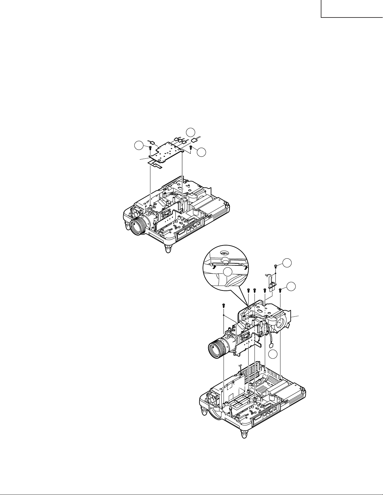
3. Ausbau der Betriebs-Platine
3-1. Die zwei Sperrschrauben von der Betriebs-Platine entfernen, und dann die Platine leicht anheben.
3-2. Die Steckverbinder abtrennen.
4. Ausbau des Optikmechanismus
4-1. Die beiden Sperrschrauben von der Lampenfassung entfernen.
4-2. Die beiden Lampenfassungs-Leitungsbefestigungen anheben.
4-3. Die Steckverbinder abtrennen.
4-4. Die sechs Sperrschrauben vom Optikmechanismus entfernen.
3-2
3-1
3-1
Betriebs-Platinen-Einheit
PG-M25X
4-2
4-1
4-4
Optikmechanismus
4-3
59
Page 60
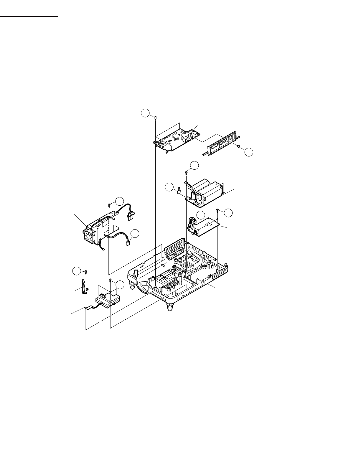
PG-M25X
5. Ausbau der anderen Platinen
5-1. Die Steckverbinder abtrennen.
5-2. Die vier Sperrschrauben von der Betriebsstrom-Platine entfernen.
5-3. Die Sperrschraube von der Vorschaltdrossel-Platineneinheit entfernen.
5-4. Die drei Sechskant-Halteschrauben von der Eingangsplatine entfernen.
5-5. Die Sperrschraube von der Klemmenblock-Abdeckung entfernen.
5-6. Die drei Sperrschrauben von der PFC-Platine entfernen.
5-7. Die Sperrschraube von der Gyro-Antenne entfernen.
5-8. Die drei Sperrschrauben von der Gyro-Platine entfernen.
5-4
Eingangsplatinen-Einheit
5-2
5-5
Vorschaltdrossel-Platineneinheit
5-7
Gyro-Antenne
Gyro-Hilfsplatineneinheit
Gyro-Platineneinheit
5-3
5-8
5-1
5-1
5-1
PFC-Platineneinheit
5-6
Betriebsstrom-Platineneinheit
Unterteil
60
Page 61
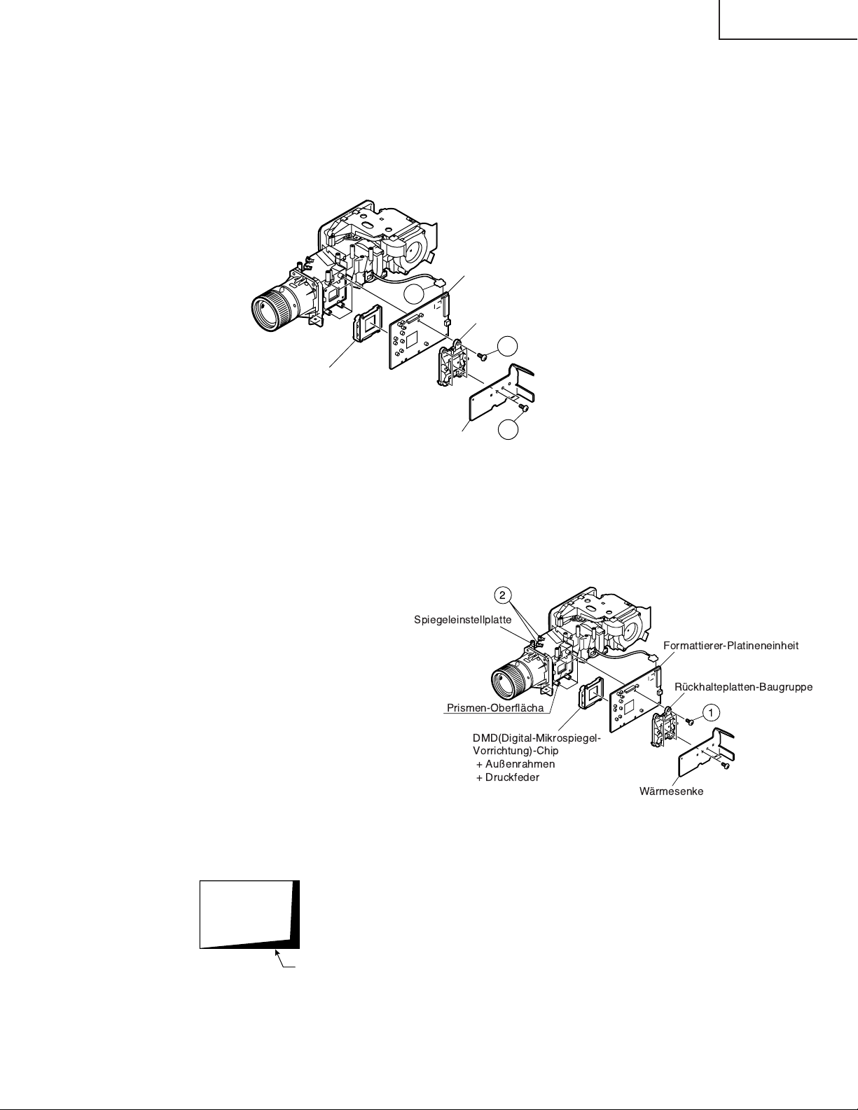
PG-M25X
6. Ausbau der Formatierer-Platine
6-1. Die Steckverbinder abtrennen.
6-2. Die beiden Sperrschrauben von der Wärmesenke entfernen.
6-3. Die vier Sperrschrauben von der Rückhalteplatten-Bügel entfernen, und die Formatierer-Platine abnehmen.
Hinweis: Die DMD(Digital-Mikrospiegel-Vorrichtung)-Einheit wird leicht durch statische Elektrizität beeinflusst.
Beim Umgang mit diesem Gerät immer ein statikableitendes Armband tragen oder andere Maßnahmen gegen
Statik treffen.
Formattierer-Platineneinheit
6-1
Rückhalteplatten-Baugruppe
6-3
DMD(Digital-Mikrospiegel Vorrichtung)-Einheit
Vorsichtsmaßregeln zur Auswechslung des DMD
(Digital-Mikrospiegel-Vorrichtung) -Chips
Hinweis: Sicherstellen, daß sich k eine Staube und
Fingerabdrücke auf dem Deckglas des
DMD-Chips und der Prismen-Oberfläche
des Optikapparats zurücklassen.
1. Beim Festziehen der 4 Schrauben der
Rü ckhalteplatten-Baugruppe die
Rückhalteplatte auf die Formatier-Platine
niederdrücken und die Schrauben diagonal
festziehen.
2. Falls ein Schatten auf dem Projektionsschirm
erscheint, wie in der Abbidlung 1, die beide
Schrauben von der Spiegeleinstellplatte lock ern
und diese Platte bewegen, um das Leuchtfeld
des DMD-Chips einzustellen.
Wärmesenke
2
Spiegeleinstellplatte
Prismen-Oberflcha
DMD(Digital-Mikrospiegel-
Vorrichtung)-Chip
+ Au§enrahmen
+ Druckfeder
6-2
Formattierer-Platineneinheit
Rckhalteplatten-Baugruppe
1
Wrmesenke
Abbildung 1
Schatten
61
Page 62
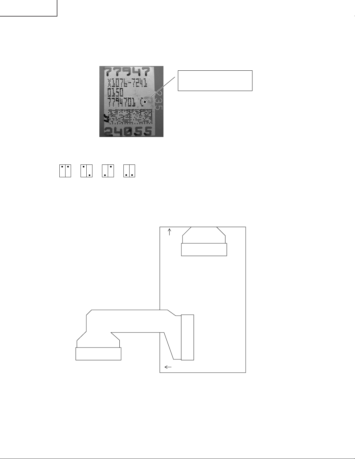
PG-M25X
* V orsichtsmaßregeln zur Einrichtung der DMD(Digital-Mikrospiegel-Vorrichtung)-Einheit
V or dem Anschließen der Formatierer-Platine an den Optikapparat die f olgenden Schritte ausführen. Die SpannngsrangMarkierung am DMD selber prüfen. Entsprechend dieser Markierung die DIP-Schalter an der Formatier-Platine einstellen.
Danach diese Platine an den Optikapparat anschließen. Falsche Einstellungen beeinträchtigen die Systemleistung.
Spannungsstand-Markierung
Diese Probe ist "C".
Spannungsrangsystem mit den DIP-Schaltern an der Formatier-Platine
BCDE
* Anschluss der FPC-Verlängerungskabel (QCNW-A298WJZZ)
Die Kabel an die Formatierer-Platine (TO FMT) und die PC-Schnittstellenplatine (TO PC) entsprechend den
Schablonendruck-Markierungen anschließen. Siehe Skizze unten. (Die FPC ist bereits an TO PC angeschlossen.)
TOFMT
62
TOPC
Page 63
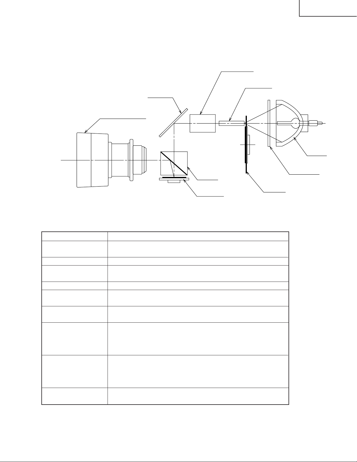
Kurzbeschreibung des Optikapparats
<Layout>
Reflektor
Projektionsobjektiv
PG-M25X
Relaislinsen
Stablinse
Lampe
UV/IR-Filter
Prisma
Gegenstand
Lampe
UV/IR-Filter
Farbrad
Stablinse
Relaislinsen
Reflektor
Prism
DMD-Chip
Projektionsobjektiv
DMD-Chip
Farbrad
Funktion
Lichtquelle. Gleichstrombetriebene HochdruckQuecksilberdampflampe.
Zur Absorption von Ultraviolett- und Infrarotstrahlen.
Dient zum Durchlassen der Lichtquelle durch den Farbfilter
und Aufspalten in die Farben R, G und B.
Dient zur Erzeugung uniformer Lichtstrahlen.
Dienen zum Sammeln des Lichts von der Stablinse in den
DMD-Chip.
Dient zum Reflektieren des Lichts von der Relaislinse gegen
den DMD-Chip.
Dient zum Einführen des Lichts vom Reflektor über die
Effektivoberfläche des DMD-Chips. Wenn der Mikrospiegel
gekippt wird (EIN) wie vorgeschrieben, wird das reflektierte
Licht zur Projektionslinse geführt.
Dient zum Einschalten und Ausschalten des Mikrospiegels
als Reaktion auf das Verhältnis der Farbkomponenten bei
jedem Punkt und deshalb zur entsprechenden Reflektion
des einfallenden Lichts.
Dient zum Vergrößern des Lichts vom DMD-Chip und zur
Projektion des Lichts auf den Schirm.
63
Page 64
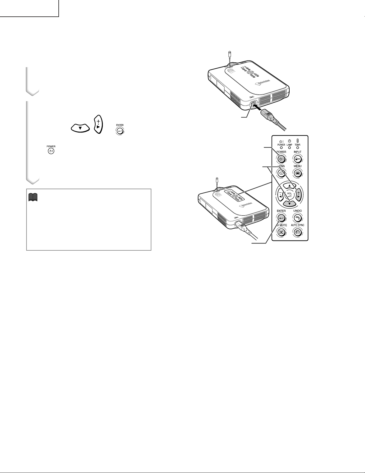
PG-M25X
RÜCKSTELLUNG DES LAMPEN-TIMERS
Den Lampen-Timer nach dem Lampenaustausch
zurückzustellen.
1
Das Netzkabel anschließen.
•
Das Netzkabel am Netzanschluss des
Projektors anschließen.
2
Den Lampen-Timer zurückstellen.
•
Während , und auf dem
Netzanschluss
Projektor gleichzeitig gedrückt wird,
auf dem Projektor drücken.
•
“LAMPE 0000H” erscheint und zeigt damit
an, dass der Lampen-Timer zurückgestellt
ist.
Info
•
Stellen Sie sicher, dass Sie den LampenTimer nur nach dem Austausch der Lampe
zurücksetzen. Wenn Sie den Lampen-Timer
zurücksetzen und dieselbe Lampe weiterhin
verwenden, könnte die Lampe beschädigt
werden oder explodieren.
POWER-Taste
Einstelltasten
""
"
(
""
ENTER-Taste
||
|
,
)
||
64
Page 65

PG-M25X
WARTUNGSANZEIGEN
■
Die Warnleuchten auf dem Projektor weisen auf Fehlfunktionen im Projektor hin.
■
Falls ein Problem auftritt, leuchtet entweder die T emperaturwarn-Anzeige oder die Lampenaustausch-Anzeige
rot auf und die Stromversorgung wird ausgeschaltet. Nach dem Ausschalten des Gerätes den unten aufgeführten
Schritten folgen.
Über die
Netz-
Anzeige
Über die Temperaturwarn-Anzeige
Wenn der Projektor wegen Problemen bei der
Aufstellung oder wegen Blockierens der
Luftffnungen zu warm wird, blinkt Ò Ó in der
unteren linken Ecke des Bildes.
Temperatur weiter ansteigt, schaltet sich die
Lampe aus und die Temperaturwarn-Anzeige
blinkt; der Khlventilator dreht sich fr weitere
90 Sekunden und anschlie§end wird die
Stromversorgung ausgeschaltet.
Ò Ó angezeigt wird, unbedingt die folgenden
Ma§nahmen durchfhren.
Wenn die
Nachdem
Temperaturwarn-
Anzeige
Lampenaustausch
Anzeige
Lampenaustausch
Anzeige
■
Wenn die Lampe
1.900 Betriebs-
stunden berschrei-
tet, blinkt Ò
gelb auf. Wenn 2.000 Betriebsstunden
erreicht werden, wird Ò
angezeigt, und die Lampe sowie der
Projektor werden automatisch
ausgeschaltet. Gleichzeitig leuchtet
Lampenaustausch
die
auf.
■
Nachdem Sie zum vierten Mal
versucht haben den Projektor
einzuschalten, ohne dass die
Lampe ausgetauscht wurde, kann
der Projektor nicht mehr
eingeschaltet werden.
-
Ó auf der Bildwand
Ó rot
-Anzeige rot
Wartungsanzeige Symptom Problem Abhilfe
Temperatur-
warn-
Anzeige
Lampenaus-
tausch-
Anzeige
Normal
Aus
Grn ein
Grn
blinkt,
wenn die
Lampe
aktiviert ist.
Unnormal
Die Temperatur
Rot ein/
Strom aus
Rot blinkt Die Lampe muss
Rot ein/
Strom aus
im Inneren des
Gertes ist zu
hoch.
ausgetauscht
werden
Die Lampe
leuchtet nicht.
•
Belftungsffnungen
blockiert.
•
Khlventilator
beschdigt
•
Interne Schaltkreise
beschdigt
•
Luftfilter verstopft
•
Die Lampenbetriebsdauer
liegt bei ber 1900
Stunden.
•
Ausgebrannte Lampe
•
Lampen-Schaltkreis
beschdigt
•
Den Projektor an einem besser
belfteten Ort aufstellen.
•
Den Projektor einem von Sharp
autorisierten Hndler fr Projektoren
oder dem Kundendienst
geben.
•
Den Projektor einem von Sharp
autorisierten Hndler fr Projektoren
oder dem Kundendienst zur Reparatur
oder zum Lampenaustausch geben.
•
Lassen Sie beim Austausch der Lampe
bitte die ntige Vorsicht walten.
zur Reparatur
65
Page 66

PG-M25X
Freigabe der Systemsperre
Das Gerät einschalten. Wenn die Systemsperre aktiviert wird, erscheint die System-Nullstellungsanzeige. Danach
sind die folgenden Tasten in der vorgeschriebenen Reihenfolge zu betätigen.
MENU → ENTER → ENTER → MENU → UNDO → UNDO → MENU
Zuerst die MENU-Taste drücken, dann die verbleibenden Tasten innerhalb von 10 Sekunden betätigen.
66
Page 67
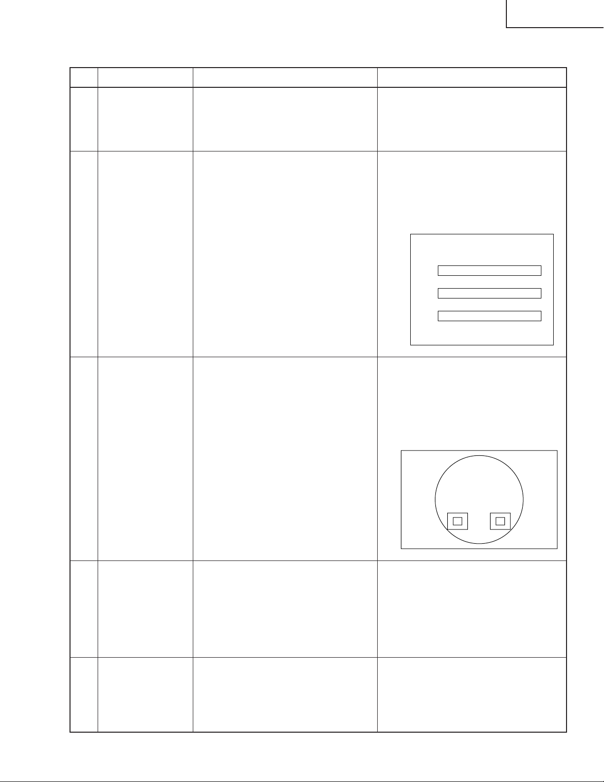
ELEKTRISCH EINSTELLUNG
Nr. Einstellposten Einstellbedingungen Einstellverfahren
PG-M25X
1 Initialisierung des
EEPROM
2 Einstellung für
CW-Index
3 Einstellung der
Reproduktion für
die RGBAbstufung
1. Das Gerät einschalten (Lampe
leuchtet auf) und das System für
15 Minuten aufwärmen lassen.
1. Signaleingang: Farbbalken mit 64
Abstufungen
2. Die nachfolgende Gruppe bzw.
die Position wählen.
Gruppe: DLP
Posten: CW-INDEX anwählen.
1. Das SMPTE-Mustersignal
zuführen.
2. Die nachfolgende Gruppe bzw.
die Position wählen.
Gruppe: DLP
Posten: G1-GAIN
1. Folgende Einstellungen ausführen.
SW200 drücken, um in den
Prozeßmodus einzutreten, dann
S2 im SSS-Menü ausführen.
1. Das Signal zu INPUT 1 leiten.
2. Den Posten anwählen und
Einstellungen vornehmen, so daß
die Lampen-Abstufungsmuster von
R, G und B weich und störungsfrei
erscheinen.
R
G
B
1. Sicherstellen, daß 100% und 95%
Weißabstufung sowie 0% und 5%
Schwarzabstufung erkennbar sind.
2. Falls die Weißabstufung
unterschiedlich erscheint, muß die
Feineinstellung durch G1-GAIN
erfolgen.
4 Einstellung für
Video/
Helligkeitskontrast
5 Einstellung auf
Video-Farbton
1. Das Fenster-Mustersignal
(NTSC100%) zuführen (BurstSignal)
2. Die nachfolgende Gruppe bzw.
die Position wählen.
Gruppe: VIDEO
Posten: AUTO
1. Das Farb-Trennsignal zuführen.
2. Die nachfolgende Gruppe bzw.
die Position wählen.
Gruppe: VIDEO
Posten: TINT
67
1. Nach der Signalzuführung ist
“AUTO” mit dem Geräteschalter
oder der Taste für die
automatische Einstellung auf der
Fernbedienung anzuwählen.
1. Den festgelegten Wert bestätigen.
Festgelegter Wert: 128
Page 68

PG-M25X
Nr. Einstellposten Einstellbedingungen Einstellverfahren
6 Einstellung der
NTSCFarbsättigung
7 Einstellung der
PAL-Farbsättigung
8 Einstellung der
SECAMFarbsättigung
9 Einstellung der
COMPO GHelligkeit
1. Das interne 8-Kanal-Trennsignal
zuführen.
2. Die nachfolgende Gruppe bzw.
die Position wählen.
Gruppe: VIDEO
Posten: N-COLOR
1. Das PAL-Farbbalkensignal
zuführen.
2. Die nachfolgende Gruppe bzw.
die Position wählen.
Gruppe: VIDEO
Posten: P-COLOR
1. Das SECAM-Farbbalkensignal
zuführen.
2. Die nachfolgende Gruppe bzw.
die Position wählen.
Gruppe: VIDEO
Posten: S-COLOR
1. Eingangssignal: 0%
Graumustersignal (480I)
2. Die nachfolgende Gruppe bzw.
die Position wählen.
Gruppe: COMPO
Posten: G-BRIGHT
1. Den festgelegten Wert bestätigen.
Festgelegter Wert: 59
1. Den festgelegten Wert bestätigen.
Festgelegter Wert: 59
1. Den festgelegten Wert bestätigen.
Festgelegter Wert: 59
1. Das Signal zu INPUT 1 leiten.
Die Einstellung so vornehmen, daß
einige Bits im Bild fehlen.
10 Einstellung für
COMPO CROffset
11 Automatische
Einstellung der
RGB-Weißbalance
12 Automatische
Einstellung der
SRGBWeißbalance
1. Das Farbdifferenzsignal (480I)
zuführen: Y 0% Helligkeit, Cb und
Cr 0% Helligkeit
Gruppe: COMPO
Posten: AUTO
1. Das Grau-Mustersignal (50%)
zuführen (XGA, 60 Hz).
2. Die nachfolgende Gruppe bzw.
die Position wählen.
Gruppe: DLP
Posten: R1-GAIN (Rot)
B1-GAIN (Blau)
1. Das Grau-Mustersignal (50%)
zuführen (XGA, 60 Hz).
2. Die nachfolgende Gruppe bzw.
die Position wählen.
Gruppe: DLP
Posten: S-R1-GAIN (Rot)
S-G1-GAIN (Grün)
S-B1-GAIN (Blau)
1. Nach der Signalzuführ ung ist
“AUTO” mit dem Geräteschalter
oder der Taste für die
automatische Einstellung auf der
Fernbedienung anzuwählen.
1. R-1 GAIN und B1-GAIN so
einstellen, daß der x-Wert 266±3
und der y-Wert 320±3 beträgt.
1. Den Wert S-R1-GAIN auf 34
einstellen.
2. S-G1-1 GAIN und S-B1-GAIN so
einstellen, daß der x-Wert 310±3
und der y-Wert 335±3 beträgt.
68
Page 69

Nr. Einstellposten Einstellbedingungen Einstellverfahren
PG-M25X
13 Automatische
Einstellung der
VideoWeißbalance
14 Automatische
Einstellung der
DTV-Weißbalance
15 Einstellung der
DLP-Spannung
(für Referenz)
1. Das Grau-Mustersignal (50%)
zuführen (NTSC, Burst-Signal).
2. Die nachfolgende Gruppe bzw.
die Position wählen.
Gruppe: DLP
Posten: V-R1-GAIN (Rot)
V-B1-GAIN (Blau)
1. Das Grau-Mustersignal (50%)
zuführen (480I,
Farbdifferenzsignal).
2. Die nachfolgende Gruppe bzw.
die Position wählen.
Gruppe: DLP
Posten: C-R1-GAIN
C-B1-GAIN
1. Den Spannungsbereich der DLPBeschreibung lesen.
2. Den Schalter gemäß dem
abgelesenen Bereich einstellen
(auf der Formatierungsplatine).
1. V-G1-1 GAIN und V-B1-GAIN so
einstellen, daß der x-Wert 265±3
und der y-Wert 298±3 beträgt.
1. C-R1-GAIN und C-B1-GAIN so
einstellen, daß der x-Wert 263±3
und der y-Wert 295±3 beträgt.
1. Die Einstellung durchführen, wenn
der DLP-Chip ausgewechselt oder
die Chip-/Formatiererkombination
verändert wurde.
2.Reihe: BCDE
Einstellwert: 1234
16 Einstellung der
Frequenz
17 Überprüfung der
Frequenz
18 Überprüfung der
W/A-Wahl
1. Die Gyro-Fernbedienung
einschalten.
2. Die Frequenz am TP5801 auf
12800000±40 Hz einstellen.
1. Die Gyro-Fernbedienung
einschalten.
1. Sicherstellen, daß ausschließlich
die Gyro-Fernbedienung aktiviert
ist.
2. Die Frequenzmessung am TP5801
vornehmen und den
Trimmerkondensator (C5835) auf
den vorgeschriebenen
Frequenzpegel einstellen.
Sicherstellen, daß die Frequenz am
TP5801 12800000±40 Hz beträgt.
1. Den W/A-Anschluß auf den "L"Pegel einstellen.
2. Das Fernbedienungskabel
zwischen dem Projektor und der
Fernbedienung anschließen.
3. Sicherstellen, daß die Funktionen
der Fernbedienung der
Spezifikation entsprechen.
19 Überprüfung der
Ausgangsw ellenf orm
Das Signal mit der Fernbedienung
übermitteln, welche für die
nordamerikanischen und die
europäischen Mär kte bestimmt sind.
69
Die Anzeige des Oszilloskops
verfolgen, um sicherzustellen, daß der
serielle Datenausgang der
Spezifikation entspricht.
Page 70

PG-M25X
Nr. Einstellposten Einstellbedingungen Einstellverfahren
20 Überprüfung im
angeschlossenen
Zustand
21 Bestätigung und
Neueinstellung
der Weißbalance
22 Bestätigung der
farbbezogenen
Operation
23 Bestätigung der
farbbezogenen
Operation
Das Gerät an den Projektor
anschließen. Sicherstellen, daß die
ferngesteuerte Registrier ung gut
funktioniert und sich der Zeiger
entsprechend bewegt.
1. Die Einstellbedingungen für jeden
einzelnen Posten sind wie folgt:
Für RGB-Eingang auf Posten 131 Bezug nehmen.
Für SRGB-Eingang auf Posten
13-2 Bezug nehmen.
Für Videoeingang auf Posten 13-3
Bezug nehmen
Für DVT-Eingang auf Posten 13-1
Bezug nehmen.
1. Das Farbbildsignal empfangen. 1. L1 im Prozeßmodus empfangen.
1. Das Monoskop-Mustersignal
empfangen.
Sicherstellen, daß keine Abweichung
in der Weißbalance auftritt (verglichen
mit der Überwachungseinrichtung).
Für die Neueinstellung in der
folgenden Reihenfolge vorgehen:
RGB-Eingang, Videoeingang und
DTV-Eingang.
Die Leistung von Farbe und
Tönung überprüfen.
1. L2 im Prozeßmodus empfangen.
Das Bild, die Bildhelligkeit und die
Bildschärfe über prüfen.
24 Bestätigung von
RGB
25 Bestätigung des
Off-TimerBetriebs
26 Bestätigung des
Thermistorbetriebs
27
Automatischer
Synchronisationsbetrieb
1. Das RGB-Signal empfangen. 1. L4 im Prozeßmodus anwählen.
Folgendes überprüfen: Bild,
Bildhelligkeit, Rot, Blau, Takt,
Phase, H-POS und V-POS.
1. OFF im Prozeßmodus anwählen.
Sicherstellen, daß der Off-Timer
mit einer 5minütigen Anzeige
beginnt, 1 Minute für 1 Sekunde
zählt und dann ausschaltet,
nachdem die Minute “0” angezeigt
wird.
1. Den Thermistor mit einem
Haarfön erwär men.
1. Das Phasen-Prüfmustersignal
empfangen.
1. Sicherstellen, daß die Temperatur
angezeigt wird.
1. Sicherstellen, daß Takt, Phase, HPOS und V-POS automatisch im
VGA/S-VGA/XGA-Modus
eingestellt werden können.
70
Page 71
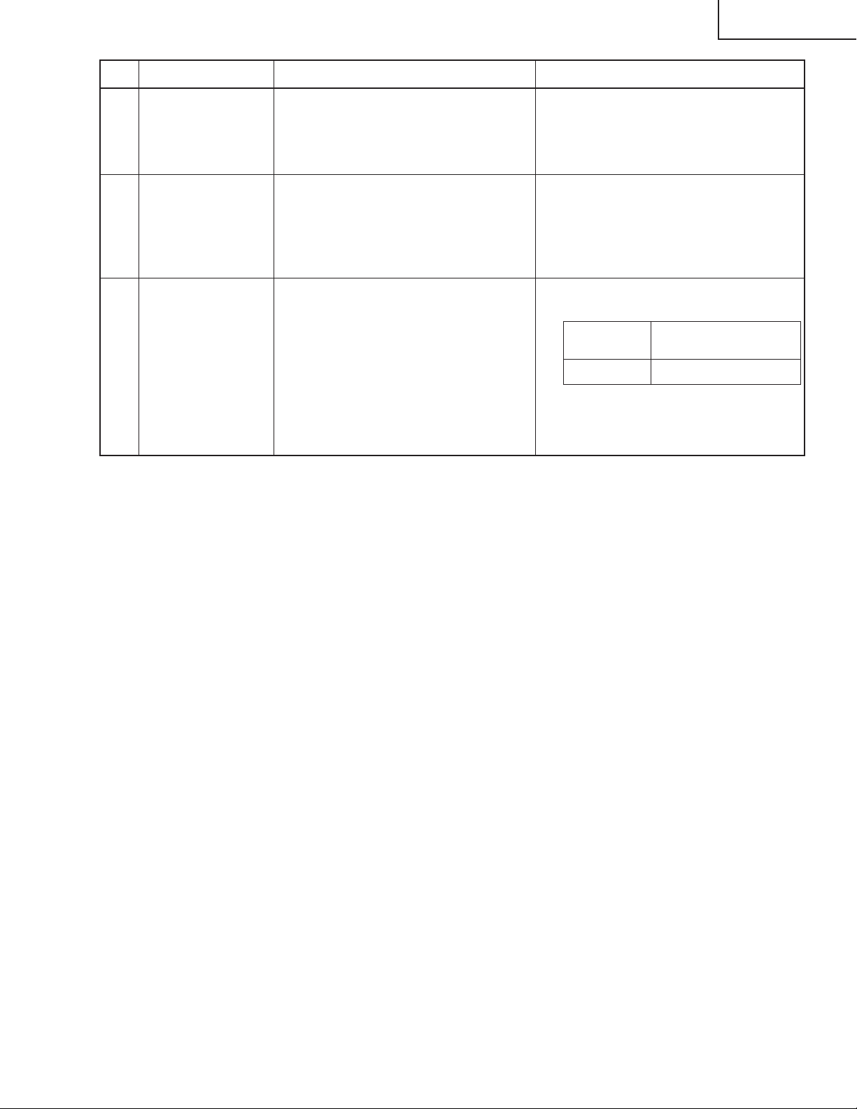
Nr. Einstellposten Einstellbedingungen Einstellverfahren
28
Leistungsprüfung
der GyroFernbedienung
Sicherstellen, daß die GyroFernbedienung wie vorgeschrieben
funktioniert.
PG-M25X
29 Leistungsprüfung
für PC-Kar te
30
Werkseinstellungen
1. Die drahtlose LAN-Karte in den
PC-Steckplatz einführen.
2. Danach die Speicherkar te mit den
Prüfmusterbildern in den PCSteckplatz einführen.
1. Sicherstellen, daß das Bild richtig
über tragen werden kann.
2. Sicherstellen, daß das Bild richtig
angezeigt werden kann.
1. Die folgenden Einstellungen
ausführen:
Prozeßein-
stellung
S4
2. Die versandfertige GyroFernbedienung registrieren.
Fernbedienungsein-
stellung
"Werkseinstellung 4"
Einstellung der PC-Platine
1. Initialisierung des EEPROM
1) SW2001 drücken, um in den Prozeßmodus einzutreten.
2) S1 auf dem SSS-Menü ausführen. (W enn S1 auf dem SSS-Menü ausgeführt wird, wird der Inhalt des EEPROMs
initialisiert.)
3) Sicherstellen, daß es sich bei der Version des Programms (Ver. XXX) um die neueste Version handelt.
2. Einstellposten
1) Einstellung für RGB-Betriebs-/Verstärkungsspannung
(1) Das Fenster-Mustersignal zuführen, welches 100%- und 0%-Signale aufweist.
(2) AUTO unter den Analog-/Digitalposten im Prozeßmodus anwählen und die Einstellung durchführen.
71
Page 72

PG-M25X
» Eingabe des Einstellprozeßmodus
Es gibt die folgenden zwei Verfahren.
» Den SW2001 an der Tastenplatinen-Einheit drücken.
» Die folgenden Tasten in der vorgeschriebenen Reihenfolge betätigen.
AV MUTE→AV MUTE→Einstell oben→Einstell unten→ENTER→ENTER→MENU
» Einstellmodus-Prozessmenü
Gruppe Untergruppe Gegenstand
APC-Bild einstellen A/D R-BRIGHT
G-BRIGHT
B-BRIGHT
R-D
B-D
G-D
AD-AUTO
DLP-Bild einstellen DLP R1-BLK
R1-GAIN
G1-BLK
G1-GAIN
B1-GAIN
CW-INDEX
S-R1-GAIN
S-G1-GAIN
S-B1-GAIN
C-R1-GAIN
C-B1-GAIN
V-R1-GAIN
V-B1-GAIN
VIDEO-Bild einstellen VIDEO PICTURE
BRIGHT
TINT
N-COLOR
P-COLOR
S-COLOR
STAT-GAIN
VIDEO-AUTO
Komponenten-Bild einstellen DTV G-BRIGHT
CB-OFFSET
CR-OFFSET
COMPO-AUTO
Prozessmodus LINE L1
L2
L3
OFF
TEMP OFF
SENSOR CHECK
ANFANGSEINSTELLUNG SSS TIME
S1
S2
S3
S4
S5
72
Page 73

Gruppe Untergruppe Gegenstand
Beispielmuster PATTERN RGB
RGB(50)
CROSS
FOCUS
SETP
COLOR
CHR
CVIC einstellen CVIC-PROGRSSIVE MODE
IP
MDSW
PTGSW
C-TESTSW
C-ILG-LY
C-MOD-LY
C-VE-LV
CVIC-ENHANCE-VIDE ENH-PLUS
ENH-MINUS
DFC
CVIC-ENHANCE-HTTV ENH-PLUS
ENH-MINUS
DFC
CVIC-ENHANCE-RGB MODE
ENH-GAIN
ENH-PLUS
CVIC-SCREEN CUBIC-RGB
CUBIC-VEDEO
CVIC-NR YNR-LEVEL
YNR-K
YNR-FSEL
CNR-LEVEL
CNR-K
CNR-FSEL
CNR-FILSW
CVIC-PTG TBL-NO
TESTSW
ENABLE
MV-F
VDDTP
CVIC-CMS RED
YELLOW
GREEN
CYAN
BLUE
MAGENTA
CVIC-DEGAMMA TABLE
Versionsprüfung usw. SPECIAL IPL
IPL2
E2PROM
ADR RD/WR
USB MODE
PG-M25X
73
Page 74
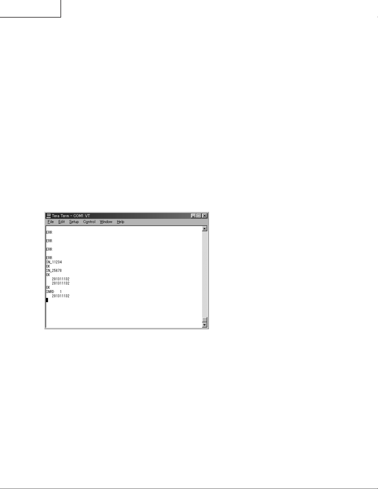
PG-M25X
Die neueste Version dieses Programms (USB-Seriell-Treiberprogramm) von der Homepage des SHARPs
“http://172.24.145.13/tcg-qrc/prj/prj-e.asp” herunterladen.
SCHRITT 1
Einrichtung für seriellen USB-Treiber
(Siehe Datei "Treiberinstallationsverfahren und Rat.doc")
SCHRITT 2
Den Einstellprozeßmodus anrufen, und die Untergruppe “SPECIAL” sowie den Einstellposten
“USB-MODE” wählen. Den USB MODE-Wert von 0 auf 1 umstellen.
(Für diese Änderung wird Eingabe eines 232C-Befehls möglich.)
SCHRITT 3
Das USB-Kabel zwischen PC und Projektor anschließen.
SCHRITT 4
Das Parameter "TeraTerm" ausführen.
(Die Konfigurationsdatei dient zur Verwendung des beiliegenden Teraterm.ini.)
SCHRITT 5
Mit Hilfe der beiliegenden Macro-Datei (serial_write.ttl) beschreiben.
Eine Seriennummer ist in dieser Macro-Datei beschrieben. Diese Nummer eingeben.
SCHRITT 6
Die Meldung erscheint wie folgt.
SCHRITT 7
Bitte T eraTerm beenden.
SCHRITT 8
Den Wert von 1 auf 0 für USB MODE in Special (Werksmodus) umstellen.
(Für diese Änderung wird Eingabe eines 232C-Befehls unmöglich.)
<Achtung>
Nach der Installation für USB zum 232C Treiber soll 232C mit SW2002 am Tasten-PC gewählt werden.
Das USB-Kabel anschließen, und COM2 für TeraTerm änder n (Ser iell-Anschluss einrichten), und dann die "ENTER"-Taste drücken und bestätigen, dass die Meldung "ERR" zurückkommt.
Wenn "ERR" zurückkommt, ist die Einstellung korrekt. Wenn "ERR" nicht zurückkommt, ist COM2 falsch.
Bitte nacheinander COM3 und COM4 probieren, und den richtigen COM-Anschluss finden.
74
Page 75
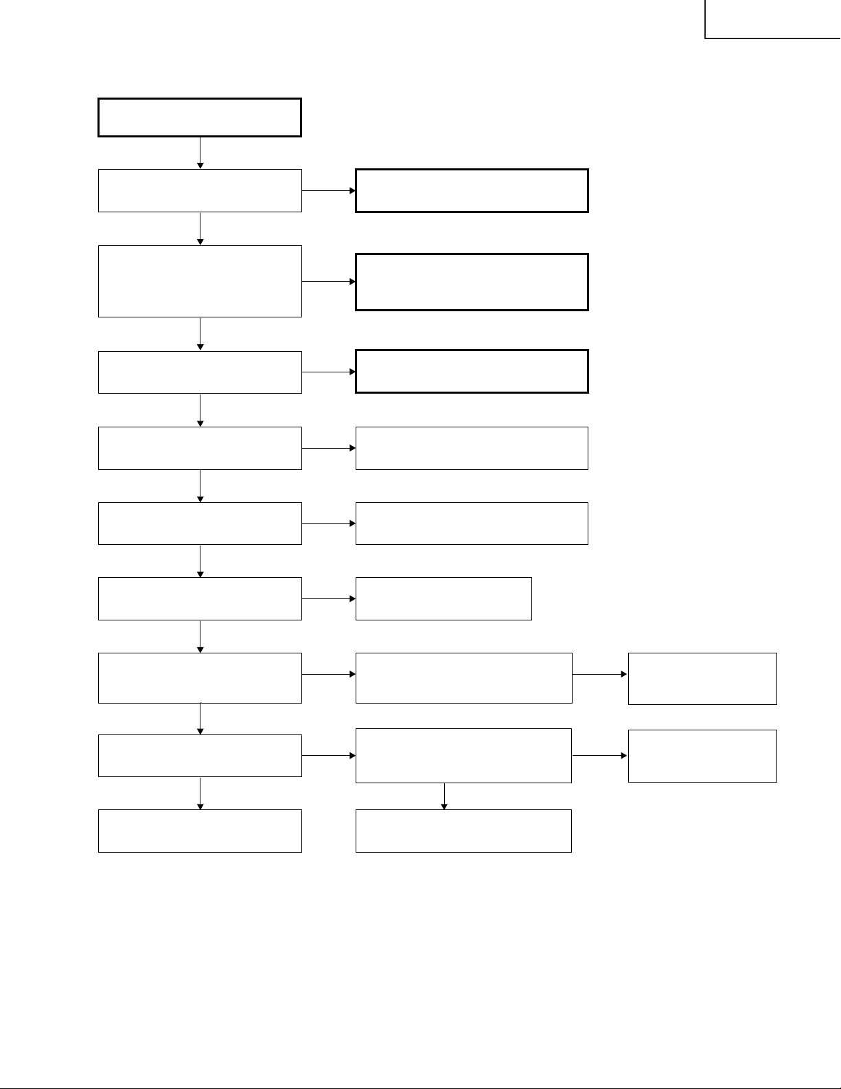
Üerprüfen der grundlegenden
Funktionen
PG-M25X
FEHLERSUCHTABELLE
Leuchtet die POWER LED auf,
oder blinkt sie in Rot bzw. Grün?
Ja
Funktioniert das Gerät durch den
Geräteschlüssel oder die
Einschalttaste auf der
Fernbedienung?
Ja
Dreht sich das Kühlgebläse und
leuchtet die Lampe?
Ja
Wird das Benutzermenü
angezeigt?
Ja
Funktioniert der RGB-Eingang
normal?
Ja
Nein
Nein
Nein
Nein
Nein
Zu “Überprüfen des Netzteils”
weitergehen.
Zu “Überprüfen des Sub-Microcomputers
und seiner zugehörigen Komponenten”
weitergehen.
Zu “Überprüfen der Lampenfunktion”
weitergehen.
Den Formatierungsschaltkreis und seine
zugehörigen Komponenten prüfen.
Den IC8013 (AD) überprüfen und zu
“Überprüfen des RGB-Eingangs” weitergehen.
Funktioniert der DVI-Eingang
normal?
Ja
Funktioniert der
Komponenteneingang/DVI-Eingang
normal?
Ja
Funktioniert der Videoeingang
normal?
Ja
Ende
Nein
Nein
Nein
Den IC8015 und seinen peripheren
Schaltkreis überprüfen.
Liegen Eingangssignale an den
Stiften (8), (17) und (23) von IC8013
vor?
Zu “Überprüfen des Videoeingangs”
weitergehen. Liegt am Emitter des
Q8002 ein Eingangssignal an?
Ja
Den IC8015 und seinen peripheren
Schaltkreis überprüfen.
Nein
Nein
Den IC3852 und seinen
peripheren Schaltkreis
überprüfen.
Den IC3852 und seinen
peripheren Schaltkreis
überprüfen.
75
Page 76
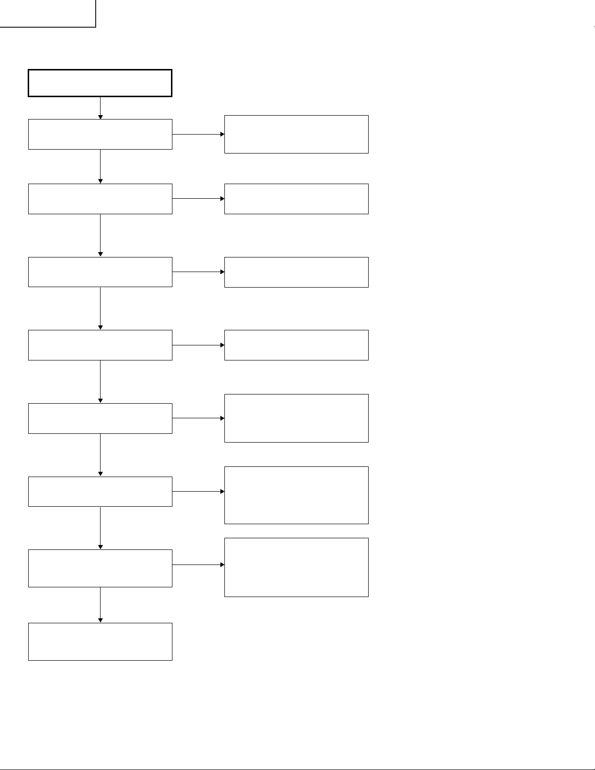
PG-M25X
Überprüfen des Netzteils
Sind die Anschlüsse des Netzteils
vollst_ndig eingesteckt?
Ja
Ist die Lampentür vollständig
geschlossen?
Ja
Funktioniert die
Temperatursicherung?
Ja
Liegt Wechselspannung am
Relais RL701 an?
Ja
Liegen ca. 6-V-Gleichspannung
am Stift (1) von CN7002 an?
Ja
Nein
Nein
Nein
Nein
Nein
Die Anschlüsse CN702, CN704,
CN7003, CN7001, CN7004 und
CN7101 vollständig einstecken.
Die Lampentür mit den Schrauben
vollständig schließen.
Die Sicherung zusammen mit
ihrem Kabelbaum ersetzen.
F701 auswechseln.
Q7501, Q7502 und Q7503 und ihre
peripheren Schaltkreise überprüfen.
Bei Defekt eines Schaltkreises muß
dieser ausgewechselt werden.
Liegen ca. 370-V-Gleichspannung
am CN702 an?
Ja
Liegt Nennspannung an den
Ausgangsanschlüssen von CN702
und CN702 an?
Ja
Die Platinenschaltkreise der
zugehörigen Ausgangsanschlüssen
überprüfen.
Nein
Nein
Die Schaltkreise überprüfen, welche an
die Primärseite von T701
angeschlossen sind. Wenn irgend ein
Schaltkreis beschädigt ist, muß er
ausgewechselt werden.
Die Schaltkreise überprüfen,
welche an die Sekundärseite von
T701 angeschlossen sind. Wenn
irgend ein Schaltkreis beschädigt
ist, muß er ausgewechselt werden.
76
Page 77

Lampe leuchtet nicht auf
(Formatiereinheit)
PG-M25X
Hat einer der Steckverbinder SC9001,
SC9002, P9002 und P9003 schlechten
oder fehlenden Kontakt?
Nein
Liegt die vorgeschriebene
Spannung an Stift (15) von
SC9002 an?
Ja
Liegt am Stift (1) von P9002 das
180 Hz Impulssignal an?
Nein
Liegt am Stift (2) von P9003 das
180 Hz Impulssignal an, wenn kein
Eingangssignal vorliegt?
Ja
Weist das Signal am Stift (10) von
IC9101 einen hohen Pegel auf?
Ja
Nein
Ja
Nein
Nein
Die Stecker vollständig einstecken.
Liegt die vorgeschriebene
Spannung an Stift (11) von
P3002 an?
Die Lampe und
Vorschaltdrosseleinheit prüfen.
Liegen die vorgeschriebenen
Spannungen an den Stiften (23)
und (24) von P3003 der EingangsPlatine an?
Zu “Überprüfen PC-Platine”
weitergehen.
Nein
Nein
Den Gebläseschaltkreis
(bei IC2101) an der
Betriebs-Platine prüfen.
Die Betriebsstromeinheit
prüfen.
Ja
Weist das Signal am Stift (9) von
IC9101 einen hohen Pegel auf?
Ja
Problem mit IC9101 oder seiner
peripheren Komponente.
Nein
Nein
Liegen an den Stiften (69) und (70)
von SC9001 hohe Signalpegel an?
Ja
Probleme mit IC9003.
77
Page 78
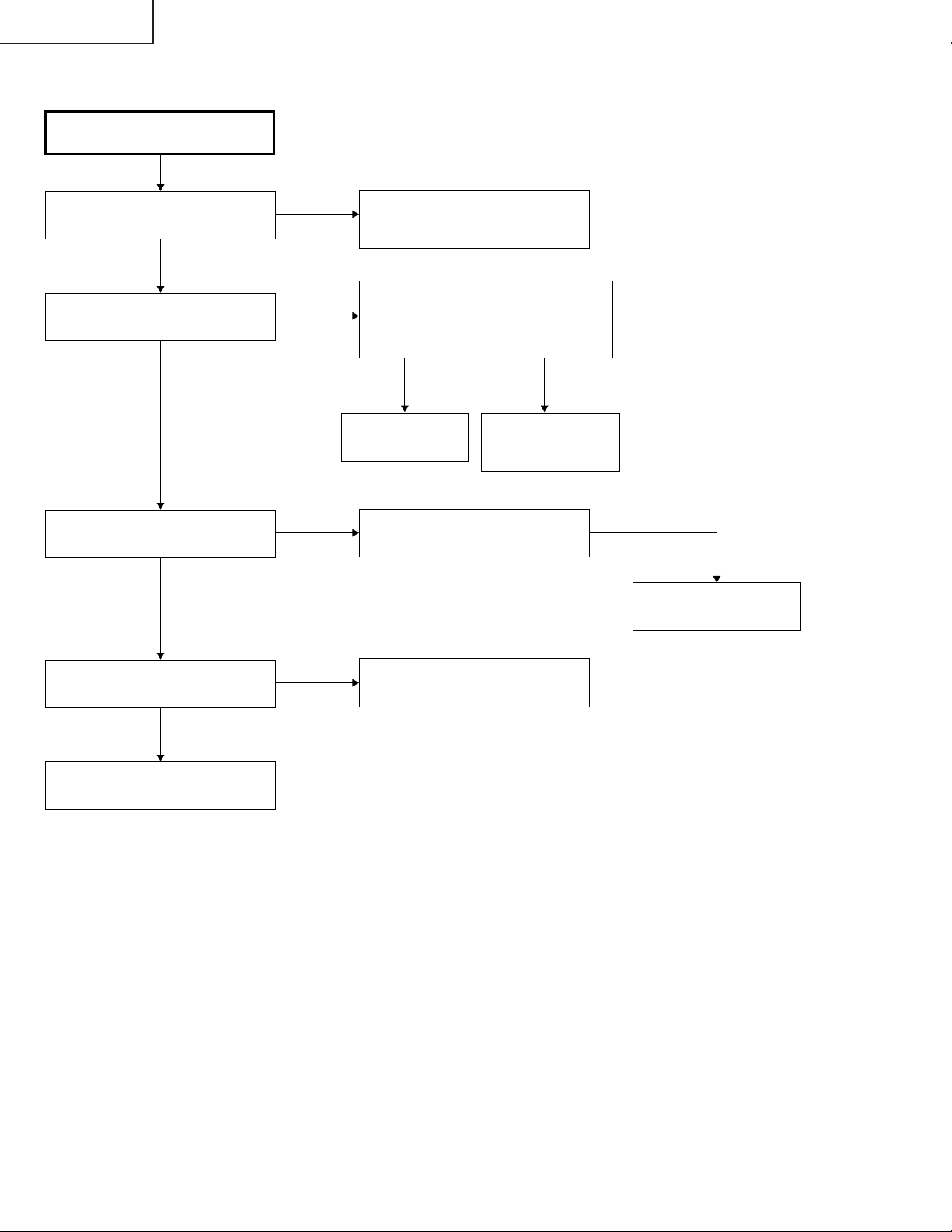
PG-M25X
Die Lampe leuchtet nicht auf.
Ja
Dreht sich das Kühlgebläse?
Ja
Ist der Rotationston der
Farbscheibe hörbar?
Ja
Ist der Lampen-Entladungston
hörbar?
Nein
Nein
Nein
Ja
Den Stromkreis der
Gebläseschaltkreises und der
Tasten/Eingangsplatine überprüfen.
Den IC3101, den Motorantriebs-Schaltkreis
und ihre zugehörigen Komponenten
überprüfen.
Die Wellenform von SC3101 überprüfen.
Normal Abnormal
Die Farbscheibe
auswechseln.
Die Fassung überprüfen.
Die
Formatierungsplatine
überprüfen.
Nein
Die Lampe auswechseln.
Liegen 340-V-Gleichspannung am
Vorschaltgerät an?
Ja
Zu "Lampe leuchtet nicht auf
(Formatiereinheit)" gehen
Nein
Den Hauptstromkreis überprüfen.
78
Page 79
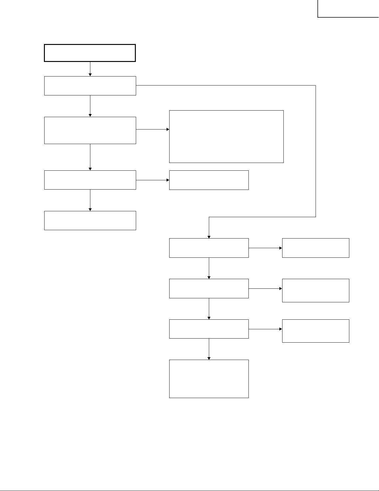
Nein
Ja
Nein
Ja
Ja
Nein
Nein
Ja
Ja
Nein
Ja
Nein
Überprüfen des Sub-Microcomputers
und seiner zugehörigen Komponenten
Blinkt die POWER LED in Rot (für
2 Sekunden)?
Liegt ein Spannungsausgangssignal
von B+3,3 V an den Stiften (12) und
(13) des CN3701 an?
Liegt ein Ausgangssignal von 6 V an
den Stiften (5) und (6) des P2003 an?
Zu “Überprüfen des Netzteils”
weitergehen.
Zu “Überprüfen der PC-Schnittstelle”
weitergehen und den flexiblen Stecker
überprüfen.
Kommunikationsfehler des SubMikrocomputers (KEY) und des SHMikrocomputers (PC-Platine) Stift (20) und
(21) von P2001.
Q2001 bis Q2004 von IC2001
überprüfen.
Wird das Bu+6,2-V-Signal
ausgegeben?
Wird das Bu+3,3-V-Signal
ausgegeben?
Liegt am Stift (19) von IC2001
ein 3,3-V-Ausgangssignal an?
Den IC2001 und seine
zugehörigen Komponenten
überprüfen und zu “Überprüfung
der FernbedienungsKommunikation” weitergehen.
Zu “Überprüfen des
Netzteils” weitergehen.
Den IC2010 und seinen
peripheren Schaltkreis
überprüfen.
Den IC2010 und seinen
peripheren Schaltkreis
überprüfen.
PG-M25X
79
Page 80
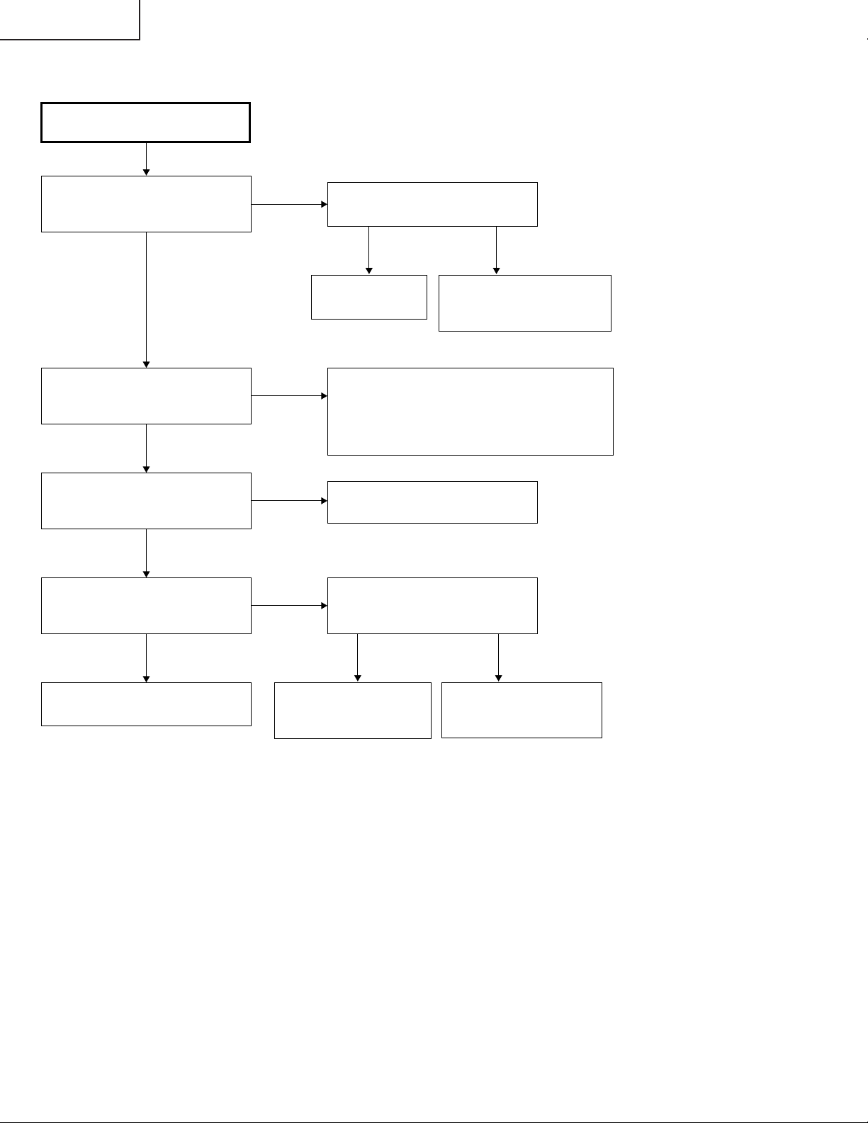
PG-M25X
Überprüfen des Tiefpaß-Filters
Wird das Videosignal den Stiften
(4), (8) und (12) des IC3851
zugeführt?
Ja
Wird das Videosignal den Stiften
(24), (21) und (17) des IC3851
zugeführt?
Ja
Wird das Videosignal den Stiften
(16), (20) und (24) von IC3001
zugeführt?
Ja
Der Tiefpaß-Filterschaltkreis an
der Eingangsplatine ist normal.
Erscheint ein Bild?
Ja
Nein
Nein
Nein
Nein
Die Stifte (4), (8) und (12) von
SC3001 überprüfen.
Normal Abnormal
Q3854 und Q3855
überprüfen.
Der IC3851 ist defekt.
Wenn die Bildqualität abnormal ist, überprüfen, die
folgenden Spannungen am Stift (28) von IC3851
anliegen. 0,3 V für 480i, 1 V für 720p, 1080i. Den
IC301 überprüfen.
Q3851, Q3852, Q3853 und ihre
zugehörigen Komponenten überprüfen.
Wird das Videosignal den Stiften (8),
(17) und (23) von IC8013 (AD9888)
der PC-Platine zugeführt?
Ja Nein
Die PC-Schnittstelle überprüfen.
Den DVI-Eingang (analog)
überprüfen.
Ende
Den SOG-Schaltkreis oder den
IC8013 und seine zugehörigen
Komponenten überprüfen.
80
Den IC8013 und seine
zugehörigen Komponenten
überprüfen.
Page 81

Nein
Nein
Ja
Ja
Nein
Ja
Ja Nein
Ja
Abnormal
Nein
Auf den Normalzustand zurückgestellt.
Ja
Ja
Nein
Überprüfen des DTV (480iKomponenten-Signaleingang)
Das 480i-Komponentensignal dem INPUT 1 zuführen.
INPUT 1 mit der Gerätetaste bzw. mit der Fernbedienung
anwählen.
Auf der Benutzermenü-Anzeige 480i unter den Spezialmodi
auswählen.
Wird ein Bild ausgegeben?
Ist die Farbe normal?
Erscheinen die Bildumrisse
scharf?
Ende
Bestätigung der Synchronisation.
Wird das Y-Signal einschließlich
des Synchronisationssignals dem
Stift (3) von IC3502 zugeführt?
Ist der Signaltyp mit der
Komponente abgestimmt?
Den Signaltyp
festlegen.
Wenn Ausgabe über den Monitor
vorliegt, das Monitorkabel
abziehen.
Den Monitorausgang einstellen.
Die Monitorausgang-Einrichtung
und das Kabel überprüfen.
Wurde 480i unter den Spezialmodi
auswählt?
Der IC8025 ist
defekt.
480i anwählen.
Zu “Überprüfen des
TiefpaßFilterschaltkreises”
weitergehen.
Den IC8016
(Videorecorder)
überprüfen.
Den IC3501 und seine
zugehörigen
Komponenten
überprüfen.
PG-M25X
81
Page 82
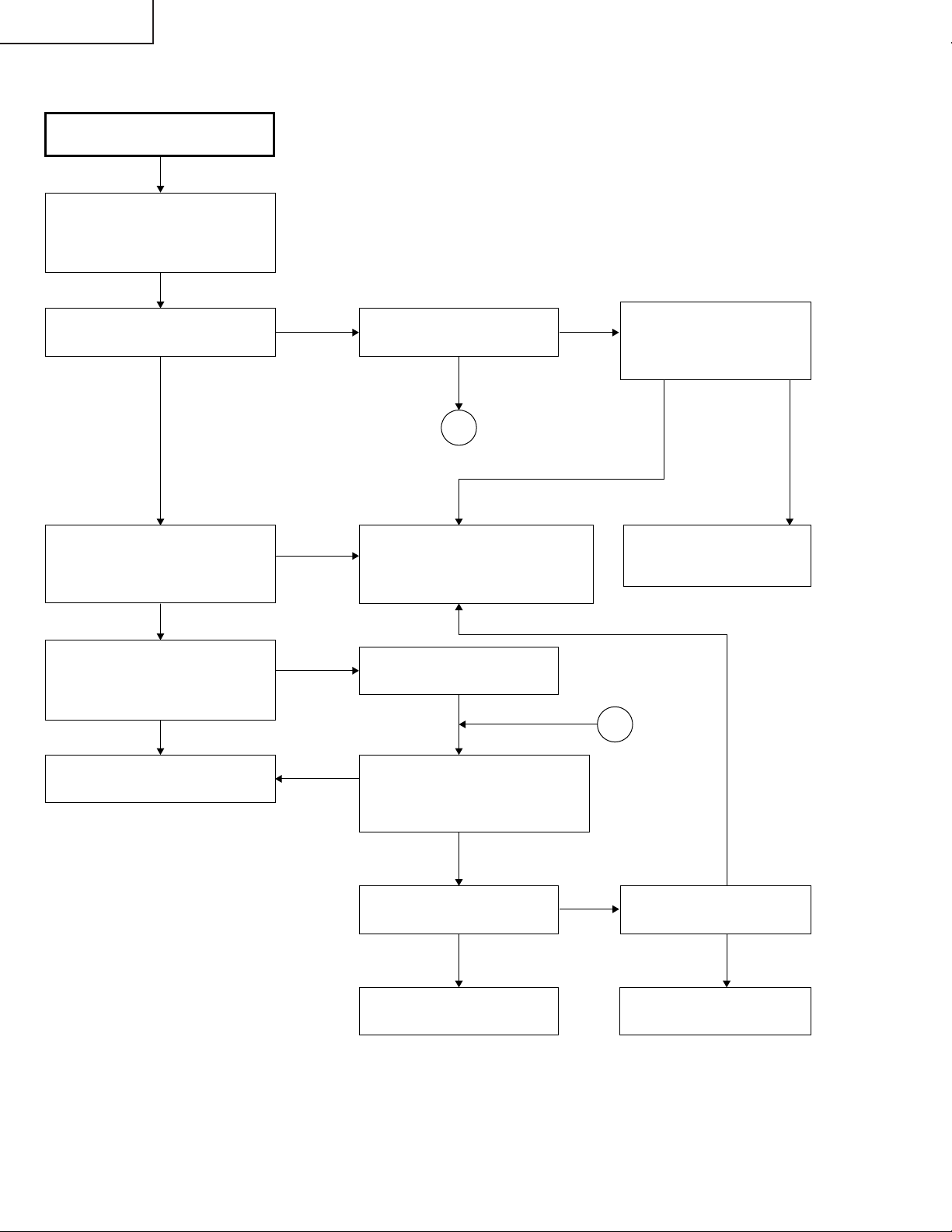
PG-M25X
Überprüfen des Videoeingangs
Das Farbbildsignal dem INPUT 3
zuführen. INPUT 3 mit der
Gerätetaste bzw. mit der
Fernbedienung anwählen.
Wird ein Bild ausgegeben?
Nein Nein
Wird das Videosignal einschließlich
dem Synchronisationssignal an Stift
(3) von SC3001 der Eingangsplatine
zugeführt?
Nein
Wird das Videosignal einschließlich
dem Synchronisationssignal an Stift (7)
von IC3501 der Eingangsplatine
zugeführt?
Nein
Den IC3501 und seinen peripheren
Schaltkreis überprüfen.
Ja Ja
Ja
Ja
Nein
Bestehen Bildstörungen?
1
Den IC8016 (Videorecorder) der
PC-Platine und seine zugehörigen
Komponenten überprüfen.
Q8002 überprüfen.
Q3512 und Q3513 auf der
Eingangsplatine überprüfen.
Das S-Videosignal dem INPUT 2
zuführen. INPUT 2 mit der
Gerätetaste bzw. mit der
Fernbedienung anwählen.
Ja
Werden 5pm-Signale
(horizontal) und 10pm-Signale
(vertikal) dem IC8363 der PCSchnittstelle zugeführt?
Nein
IC8363 und IC8025 (CVIC2)
und ihre zugehörigen
Komponenten überprüfen.
1
Ja
Ist die Farbe normal?
Ja
Ende
82
Nein
Ja
Wird das C-Signal dem Stift
(11) von SC3001 zugeführt?
Nein
Q3502 auf der
Eingangsplatine überprüfen.
Page 83

» FORMATTER Unit
PG-M25X
Abnormales Bild
Abbildung (gleicht
Regenbogen)
Leuchtet die Lampe?
Liegen an den Stiften (3),
(5) und (7) von SC9001
Signale an?
Ja
Probleme mit IC9003, IC9006
und den zugehörigen
Komponenten.
Ist einer der Stecker von SC9001,
SC9002, P9002 und P9003 abgezogen
bzw. weist schlechten Kontakt auf?
Nein
Nein
Stromausfall
Nein
Nein Ja
Zu “Überprüfen der PCPlatine” weitergehen.
Ja
Zu “Lampe leuchtet nicht auf”
weitergehen.
Die Stecker vollst_ndig
einstecken.
Andere
Wird dem SC9002 die geeignete
Spannung zugeführt.
Ja
Die DMD, die optische Kamera und die
Formatierungsplatine zusammenbauen.
Verbessert sich das Symptom?
Neino
Liegt die korrekte Spannung (+7 V) am
positiven Stift von C9006 an?
Ja
Liegt die korrekte Spannung (+23 bis
+26 V) am positiven Stift von C9068 an?
Ja
Liegt die korrekte Spannung (-26 V) am
negativen Stift von C9562 an?
Ja
Nein
Ja
Nein
Nein
Nein
Die Regulator-ICs an der
Eingangs-Platine und BetriebsPlatine prüfen.
Ende
Probleme mit dem peripheren
Schaltkreis C9066 bzw. mit
dem IC9003.
Probleme mit dem peripheren
Schaltkreis C9068 bzw. mit
dem IC9003.
Probleme mit dem peripheren
Schaltkreis C9562 bzw. mit
dem IC9003.
Probleme mit dem DMD.
83
Page 84

PG-M25X
» PC I/F Unit-1/12
Überprüfen der PC-Platine
0
Wird das Benutzermenü
angezeigt?
Nein
Die Bildschirmanzeige
überprüfen.
Den RGB-Eingang überprüfen.
Den Komponenteneingang
überprüfen.
Den Videoeingang überprüfen.
Ja
Den DVI-Digitaleingang
überprüfen.
Die PC-Karte überprüfen.
Ende
84
Page 85

» PC I/F Unit-2/12
Überprüfen der Bildschirmanzeige
PG-M25X
Wird das Benutzermenü
normalerweise durch die MENUTaste angezeigt?
Nein
Das Prozeßmenü eingeben und
PATTERN anwählen. Danach das
COLOR-Muster wählen.
Die Farbe der Bildschirmanzeige
normal?
Ja
Die STEP-Signalwahl durchführen.
Ist das STEP-Signal normal?
Ja
Nein
Ja
Die Bildschirmanzeige ist normal.
Das DLP-System im ProzeßEinstellmodus einstellen.
0
Die Bildschirmdaten andern.
Nein
Ist das Signal mit dem STEPSignal kompatible (am TL106 bis
TL111 vorhanden).
Ja
Zu “Überprüfen von GA4 und
seine zugehörigen Komponenten”
weitergehen.
Die Bildschirmdaten ändern.
Nein
0
Der IC8025 ist defekt.
85
Page 86
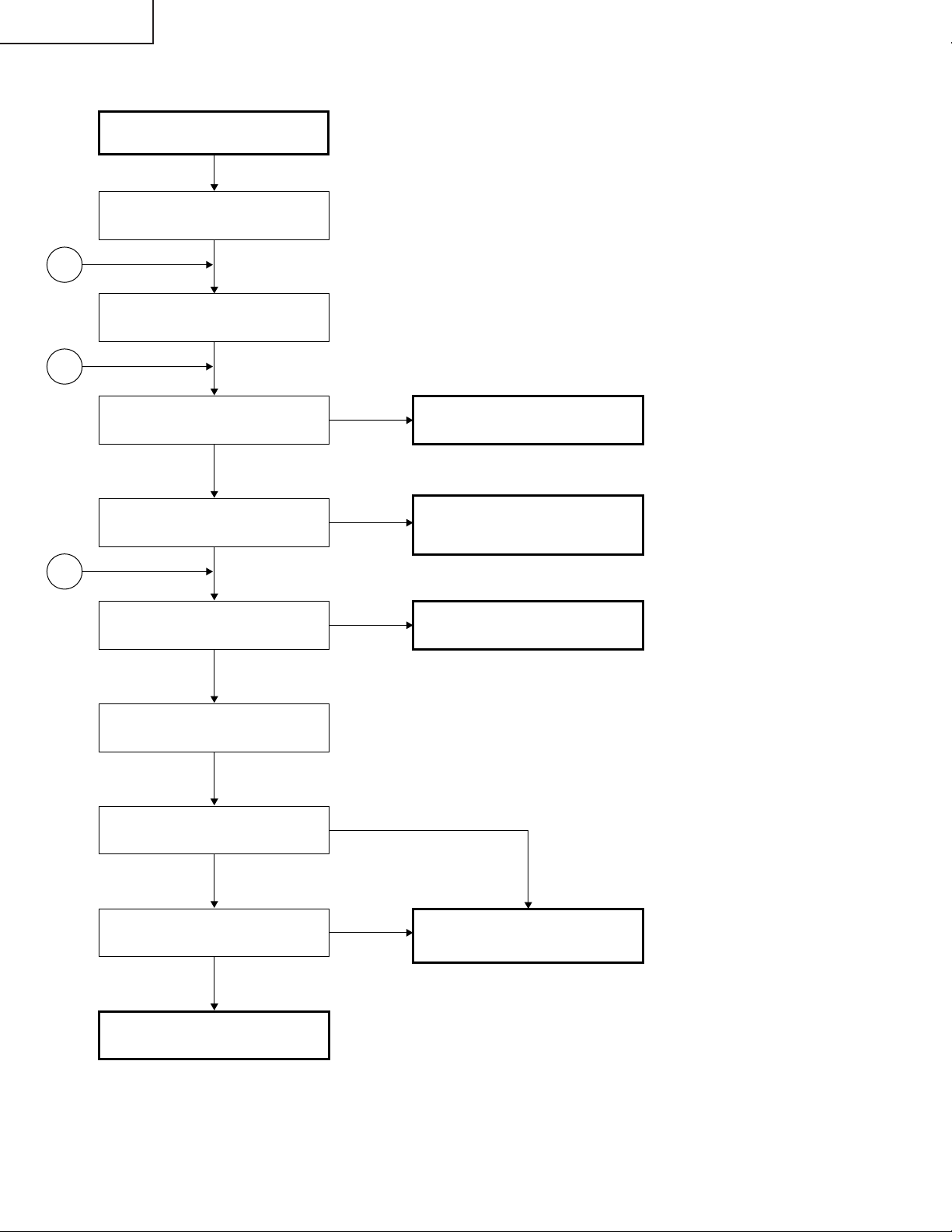
PG-M25X
» PC I/F Unit-3/12
Überprüfen des RGB-Eingangs
Das RGB-Signal (SynchronisationstypAnalogsignal) dem INPUT 1 zuführen.
1
INPUT 1 mit der Gerätetaste bzw.
mit der Fernbedienung anwählen.
2
Erscheint das Bild?
Ja
Ist das Bild gestört?
Nein
3
Erscheinen die drei Farben R, G
und B?
Ja
Den AUTOSYNC-Prozeß
ausführen.
Erscheinen die Bildumrisse
scharf?
Nein
Ja
Nein
Nein
Zu “Bestätigen des
Videoeingangs” weitergehen.
Zu “Überprüfen des
Synchronisationssignals”
weitergehen.
Zu “Überprüfen des RGBSignals” weitergehen.
Ja
Liegt eine Störung im VertikalStreifenmuster vor?
Nein
Ende
Ja
IC8013, IC8025 oder seine
zugehörigen Komponenten sind
defekt.
86
Page 87

» PC I/F Unit-4/12
Bestätigung des Videoeingangs
“Bestätigung der EingangssignalEinstellung” vornehmen.
PG-M25X
Liegt am C8070 ein Videosignal
vor?
Ja
Zu “Überprüfen des
Synchronisationssignals”
weitergehen.
IC8025 oder IC8013 sind defekt.
Bestätigung der EingangssignalEinstellung
Wurde das Eingangsmenü korrekt
angewählt?
Ja
Nein
Nein
Liegt am Anschluß C2 von P8001
(DVI-Stecker) ein Signal an?
Ja
Defekt innerhalb des
Signalverlaufs. Die Kondensatoren
und Widerstände zwischen dem
Stecker und IC8013 überprüfen.
Die Signalquelle bzw. der Stecker
sind defekt.
Das Eingangsmenü richtig
einstellen.
Nein
Sind die Stecker richtig
angeschlossen?
Ja
Ende
Nein
2
Die Stecker ordnungsgemäß
anschließen.
1
87
Page 88

PG-M25X
» PC I/F Unit-5/12
Überprüfen des
Synchronisationssignals
Liegt am Stift (11) von IC8363 ein
Vertikal- Synchronisationssignal
an?
Ja
Liegt am Stift (5) von IC8363 ein
Horizontal- Synchronisationssignal
an?
Ja
Liegt am TL8131 ein VertikalSynchronisationssignal an?
Ja
Liegt am TL8130 ein HorizontalSynchronisationssignal an?
Ja
Nein
Nein
Nein
Nein
Bestätigung der EingangssignalEinstellung vornehmen.
IC8330, IC8331 oder ihre
zugehörigen Komponenten sind
defekt.
IC8363 ist defekt.
Sind das Vertikal- und das
Horizontal-Synchronisationssignal
korrekt abgestimmt?
Nein
Liegt der geeignete
Signalgenerator (Eingangsquelle)
vor?
Ja
IC8330, IC8331 oder ihre
zugehörigen Komponenten sind
defekt.
Ja
Nein
Das Synchronisationssignal ist
normal. Ende der Überprüfung.
Die Signalquelle richtig einstellen.
2
88
Page 89
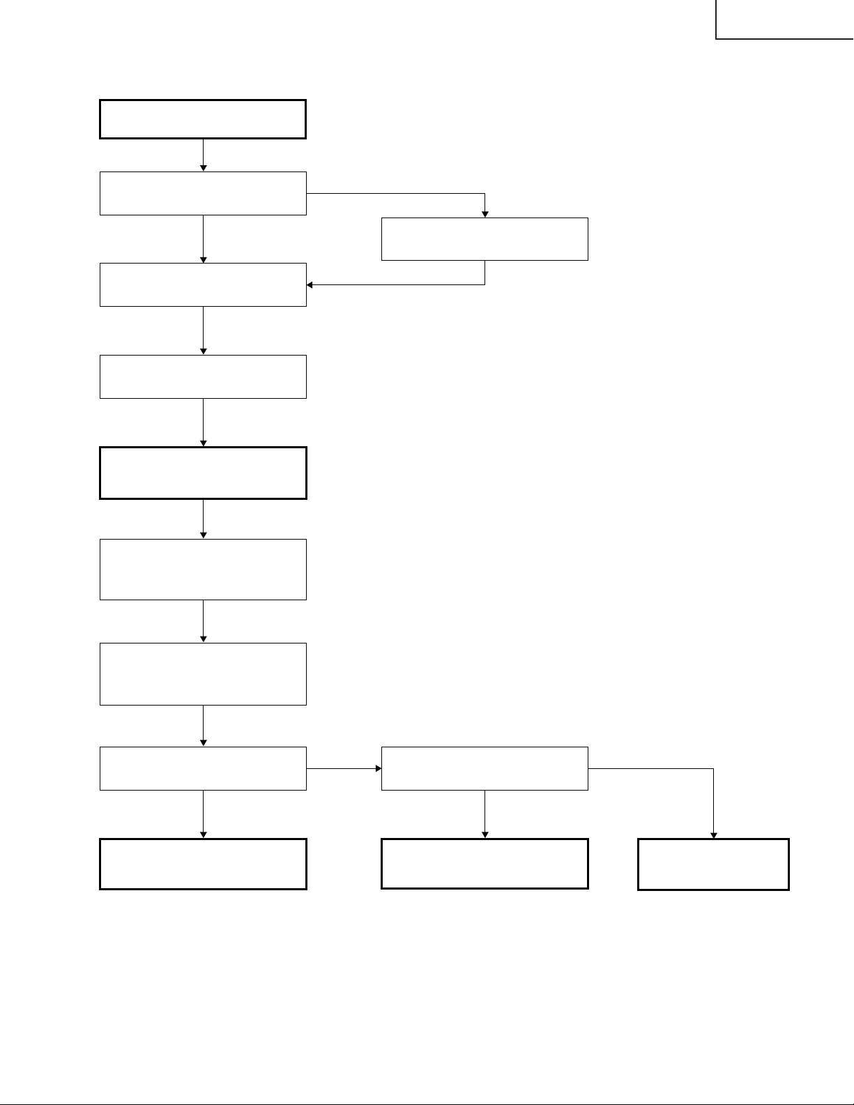
» PC I/F Unit-6/12
Überprüfen der R-, G- und BSignale
PG-M25X
Ist der Signaltyp auf RGB
eingestellt?
Ja
Den Prozeßmodus einstellen.
R, G und B einzeln auf dem
Mustermenü anwählen.
Zu “Überprüfen von GA4 und
seine zugehörigen Komponenten”
weitergehen.
Für das Überprüfen des
Eingangssignals den Signalgeber
auf das Abstufungssignal
einstellen.
Nein
Den Signaltyp auf RGB einstellen.
TL8169, TL8170 und TL8180 mit
dem Oszilloskop überprüfen.
(MSB-Bit nach der A/DWandlung)
Liegen bestimmte Signale an
TL8169, TL8170 und TL8180 an?
Ja Ja
Der IC8025 und seine
zugehörigen Komponenten sind
defekt.
Nein Nein
Werden C8062, C8070 und
C8078 Signale zugeführt?
Der IC8013 und seine
zugehörigen Komponenten sind
defekt.
Zu “Bestätigen des
Videoeingangs”
weitergehen.
89
Page 90
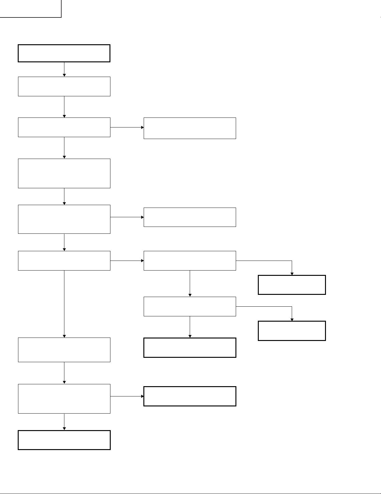
PG-M25X
» PC I/F Unit-7/12
Überprüfen von GA4 und seine
zugehörigen Komponenten
R, G und B einzeln auf dem
Mustermenü anwählen.
Wird das Bild korrekt in R-, Gund B-Signalen ausgegeben?
Nein
Die Stifte (72), (52) und (32) von
SC8001 mit dem Oszilloskop
messen. Diese Signale
entsprechen MSB von B/G/R.
Stimmen die angewählten
Signale im Mustermenü mit den
durch das Oszilloskop
gemessenen Signalen überein?
Nein
Wird das Taktsignal dem Stift (78)
von SC8001 zugeführt?
Ja
Ja
Ja
Nein
Das Überprüfen von GA4 und der
zugehörigen Komponenten ist
beendet.
Die DLP-Platine ist defekt.
Liegt ein Taktsignal von 32,5 MHz
am TL8114 an?
Nein
Liegt ein Taktsignal von 32,5
MHz am FL8110 an?
Ja
Der IC8029 ist defekt.
Nein
TL8106, TL8107, TL8108,
TL8109, TL8110 und TL8111 mit
dem Oszilloskop überprüfen.
Stimmen die angewählten
Signale im Mustermenü mit den
durch das Oszilloskop
gemessenen Signalen überein?
Ja
Der IC8029 ist defekt.
Nein
Ja
Der X8005 ist defekt.
Der IC8025 ist defekt.
Der IC8025 ist defekt.
90
Page 91
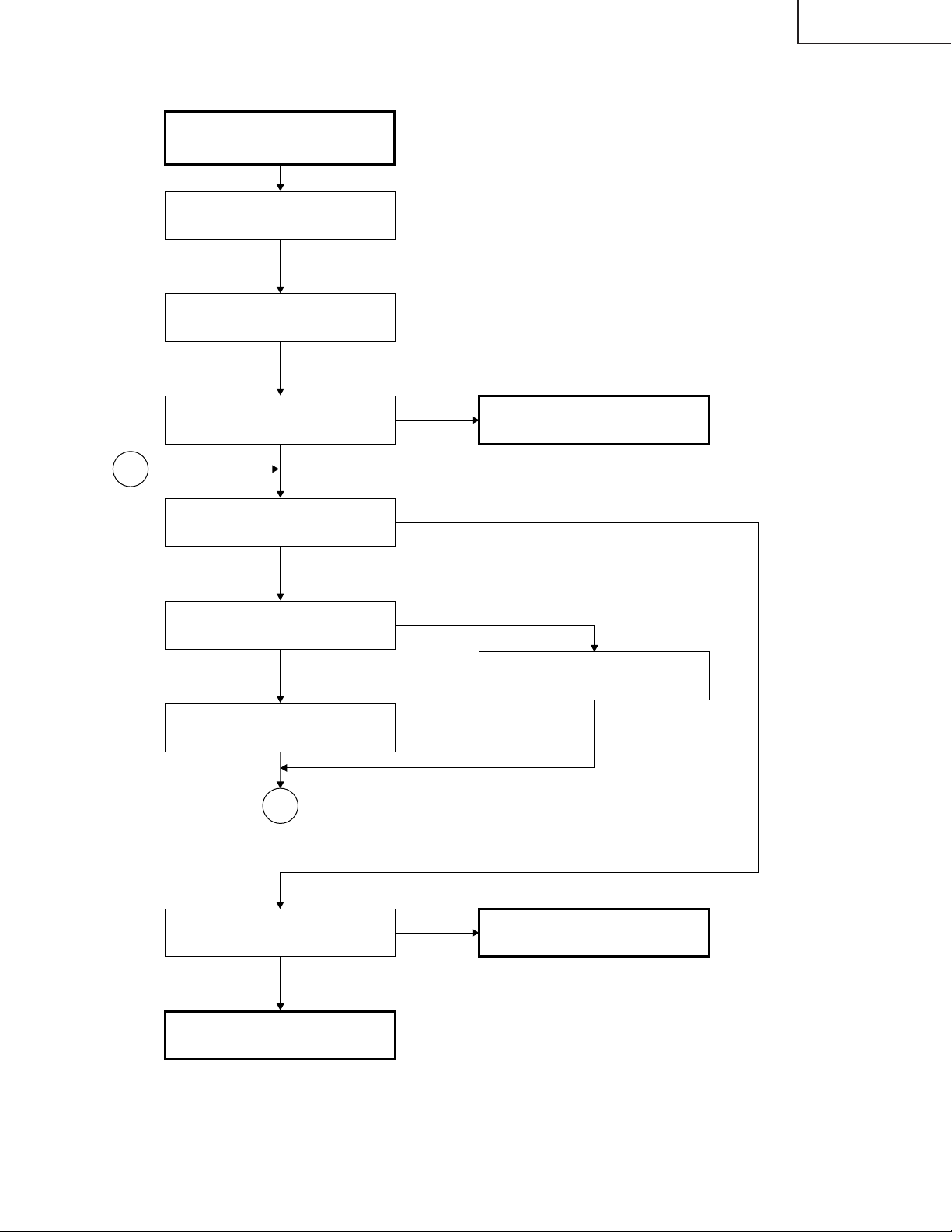
» PC I/F Unit-8/12
Überprüfen des
Komponenteneingangs
(außer 480I)
Das Komponentensignal dem
INPUT 1 zuführen.
INPUT 1 mit der Gerätetaste bzw.
mit der Fernbedienung anwählen.
PG-M25X
Erscheint das Bild?
Ja
4
Ist die Farbe normal?
Nein
Ist der Signaltyp auf die
Komponente eingestellt?
Ja
Die Prozeß-Einstellung
ausführen.
4
Nein
Nein
Zu “Überprüfen des SOGSchaltkreises” weitergehen.
Den Signaltyp auf die
Komponente einstellen.
Erscheinen die Bildumrisse
scharf?
Ja
Das Komponentensignal ist
normal. Ende.
Nein
IC8013 oder IC8025 ist defekt.
91
Page 92
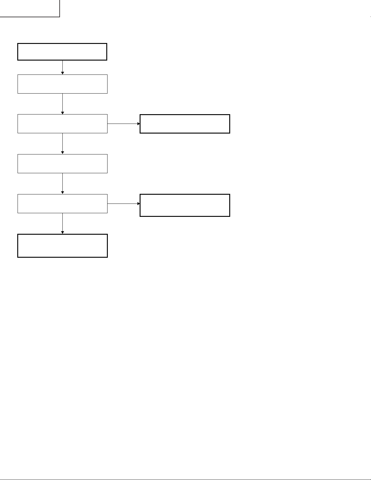
PG-M25X
» PC I/F Unit-9/12
Überprüfen des SOG-Schaltkreises
Den Stift (2) von IC8365 mit dem
Oszilloskop überprüfen.
Wird das Farbbildsignal mit dem
korrekten Timing reproduziert?
Nein
C8070 mit dem Oszilloskop
überprüfen.
Liegt ein Y-Signal (einschl.
Synchronisationssignal) vor?
Ja
Der SOG-SynchronsignalTrennschaltkreis (Eingangsplatine)
ist defekt.
Ja
Nein
Der SOG-Schaltkreis ist normal.
Ende.
Zu “Bestätigung der
Eingangssignal-Einstellung”
weitergehen.
92
Page 93
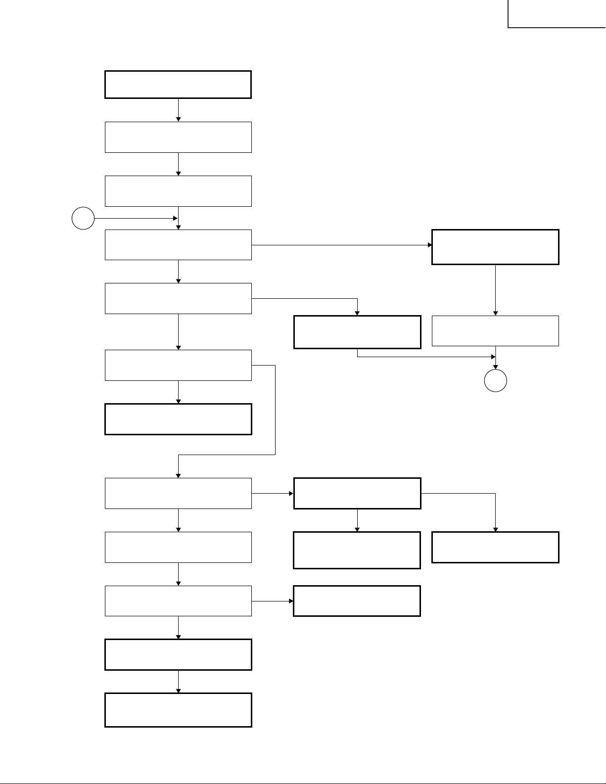
» PC I/F Unit-10/12
Nein
Ja
Nein
Nein
5
5
Nein
Ja
Nein
Ja
Ja
Ja
Ja
Nein
Überprüfen des Videoeingangs
Das Farbbildsignal dem INPUT 3
zuführen.
INPUT 1 mit der Gerätetaste bzw.
mit der Fernbedienung anwählen.
Erscheint das Bild?
Bestehen irgendwelche
Bildstörungen?
Ist die Farbe normal?
Der Videoeingang ist normal.
Ende.
Wird das Videosignal dem C8141
zugeführt?
Zu “Überprüfen des VideoSynchronsignals”
weitergehen.
Liegt am R8114 das
spezifizierte Signal an?
Der Q8002 und seine
zugehörigen Komponenten
sind defekt.
Zu “Überprüfen des VideoSynchronsignals”
weitergehen.
Die Prozeß-Einstellung
ausführen?
Die Eingangsplatine ist
defekt.
Das Taktsignal von IC8015 durch
FL8114 überprüfen.
Ist das Taktsignal normal? Der IC8015 ist defekt.
Zu “Überprüfen des VideoSynchronsignals” weitergehen.
Der IC8025 und seine
zugehörigen Komponenten sind
defekt.
PG-M25X
93
Page 94
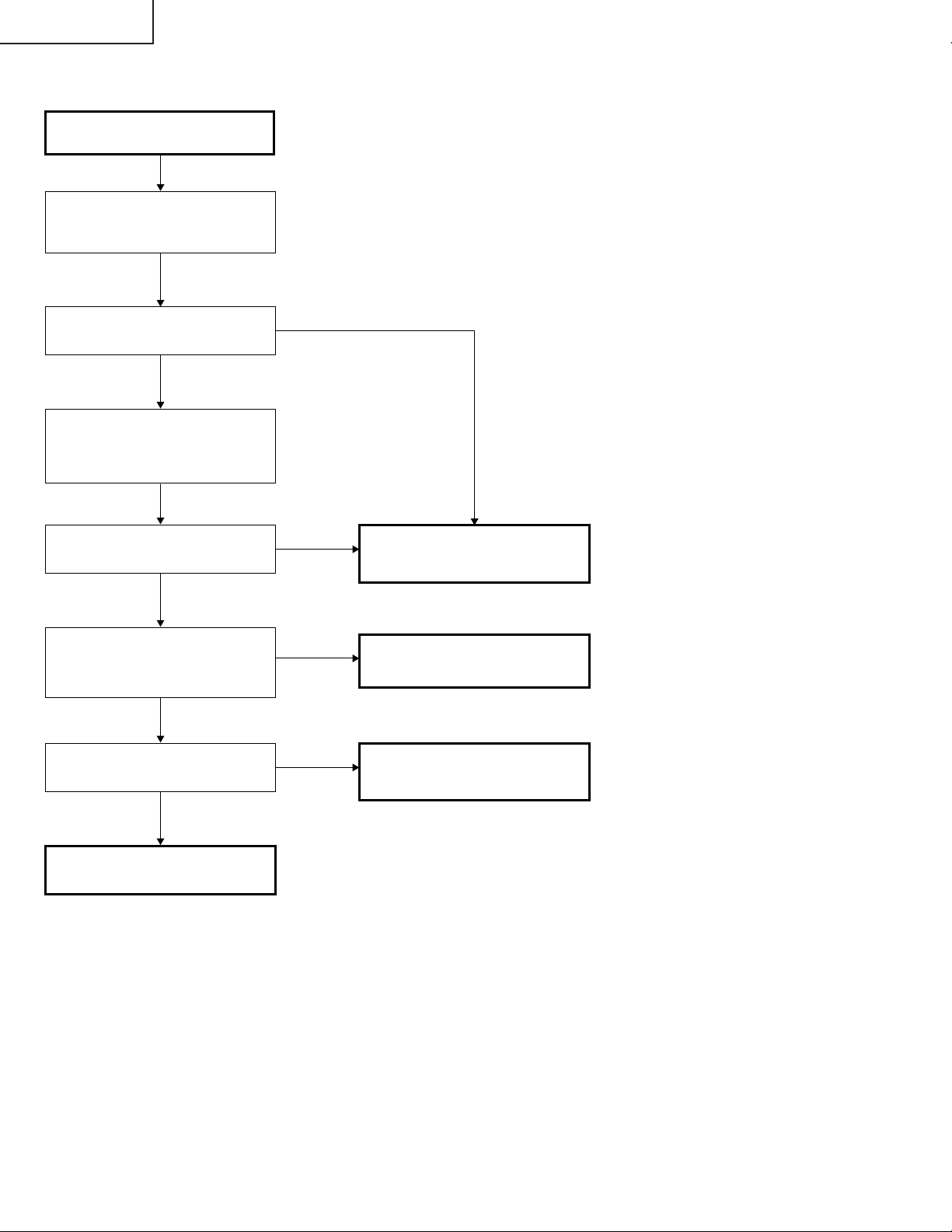
PG-M25X
» PC I/F Unit-11/12
Überprüfen des VideoSynchronsignals
Den Stift (10) von IC8363 mit dem
Oszilloskop überprüfen. (Überprüfen
des Vertikal-Synchronsignals)
Ist das Vertikal-Synchronsignal
normal?
Ja
Den Stift (6) von IC8363 mit dem
Oszilloskop überprüfen.
(Überprüfen des VertikalSynchronsignals)
Ist das Horizontal-Synchronsignal
normal?
Ja
Werden das HorizontalSynchronsignal und das VertikalSynchronsignal an TL8130 und
TL8131 ausgegeben?
Ja
Liegt am FL8114 ein bestimmtes
Taktsignal (13,5 MHz) an?
Ja
Nein
Nein
Nein
Nein
Zu “Bestätigung der
Eingangssignal-Einstellung”
weitergehen.
Der IC8015 und seine
zugehörigen Komponenten sind
defekt.
Der IC8015 und seine
zugehörigen Komponenten sind
defekt.
Ende
94
Page 95
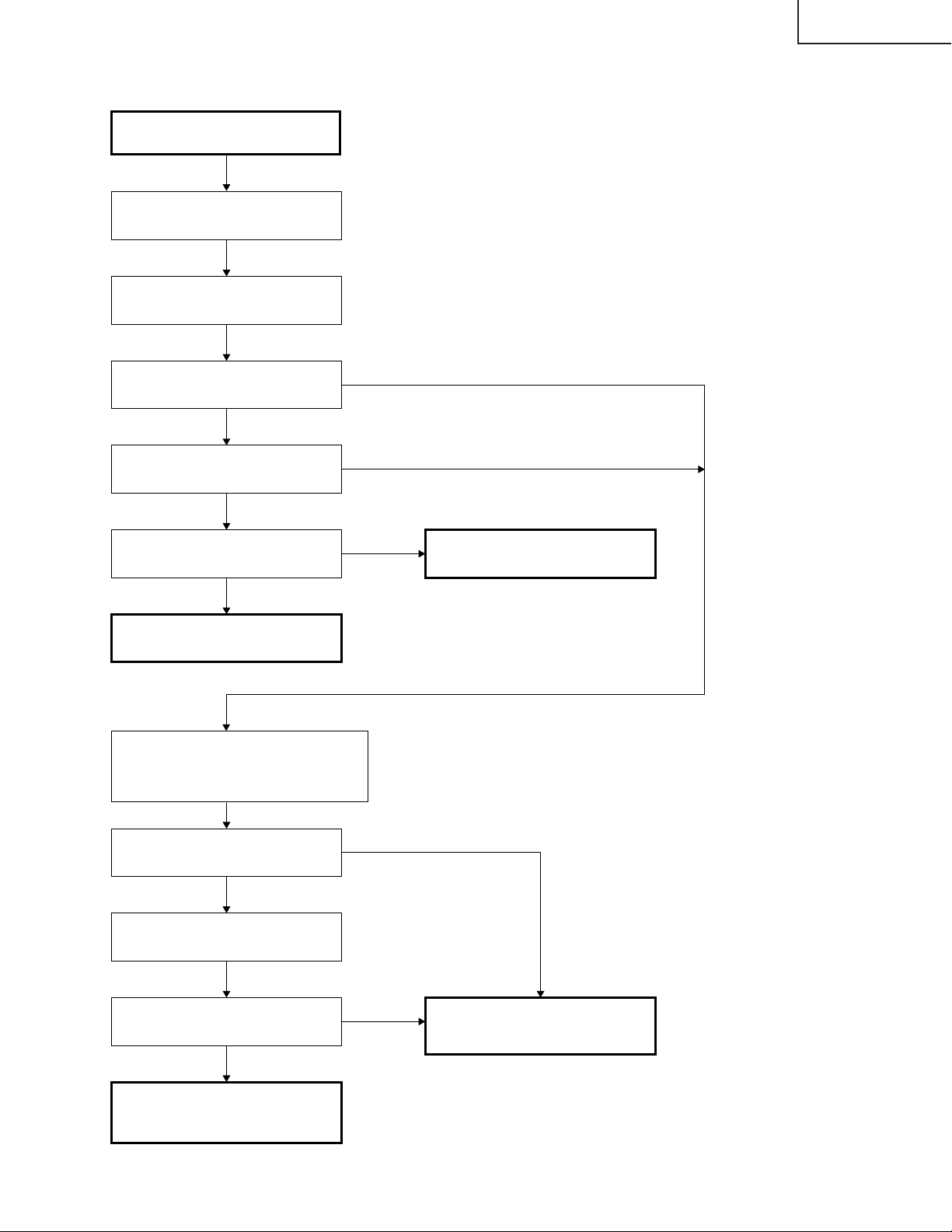
» PC I/F Unit-12/12
Überprüfen des DVI-Digitaleingangs
Das DVI-Digitalsignal dem INPUT 1
zuführen.
INPUT 1 als Eingang wählen.
PG-M25X
Erscheint das Bild?
Ja
Treten irgendwelche Bildstörungen
auf?
Ja
Ist die Farbe normal?
Ja
Der DVI-Eingang ist normal.
Den Stift (13) von IC8363 auf VertikalSynchronsignale und den Stift (3) des
IC8363 auf HorizontalSynchronsignale überprüfen.
Nein
Nein
Nein
Der IC8298 und seine zugehörigen
Komponenten sind defekt.
Sind die Synchronisationssignale
normal?
Ja
Überprüfen, ob am R8685 ein
Taktsignal vorherrscht.
Ist das Taktsignal normal?
Ja
Der IC8025 und seine
zugehörigen Komponenten sind
defekt.
Nein
Nein
Der IC8298 und seine
zugehörigen Komponenten sind
defekt.
95
Page 96
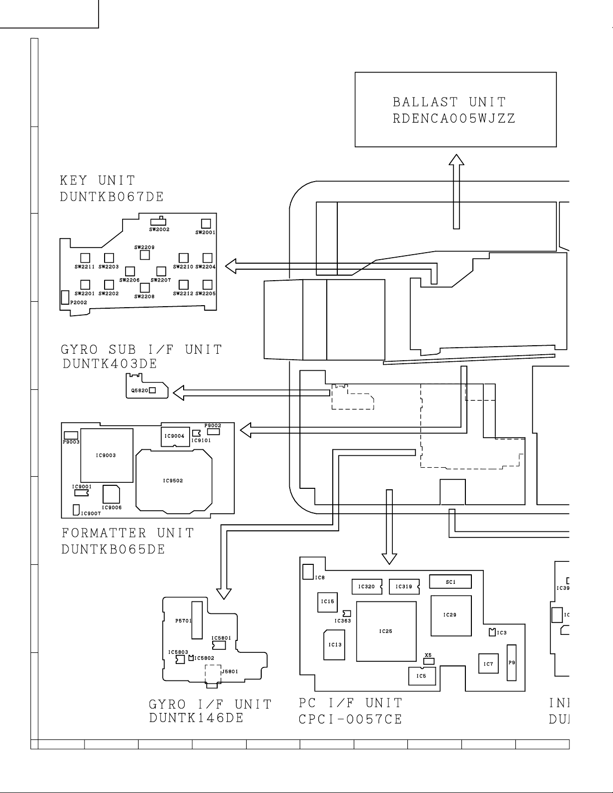
PG-M25X
CHASSIS LAYOUT/CHASSIS-ANORDNUNG
H
G
F
E
D
C
B
A
87109654321
96
Page 97
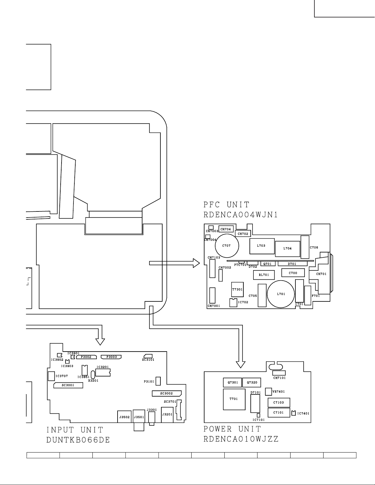
PG-M25X
97
1716 1918151413121110
Page 98
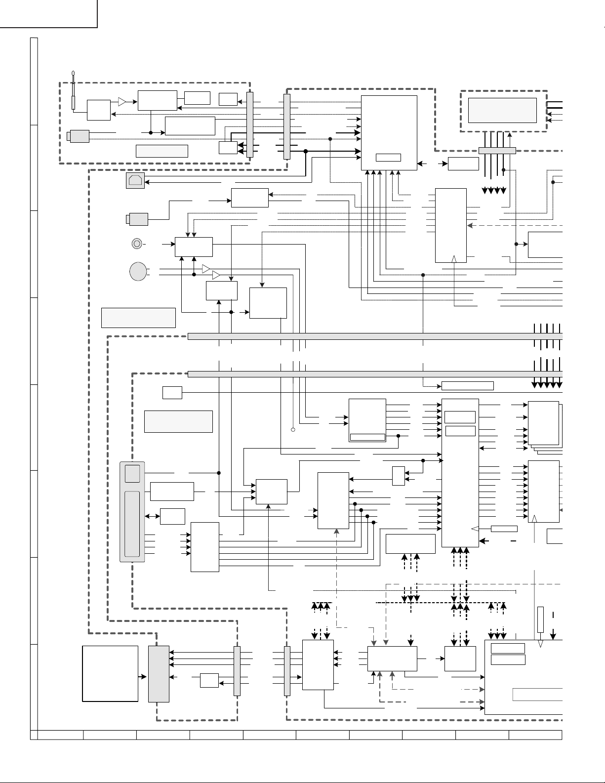
PG-M25X
O
RST SYS
3
BLOCK DIAGRAM/BLOCKCHALTBILD
H
Rod Antenna
Filter
RF-DATA
WIRED R/C
IC 5801
FM Receiver
GYRO UNIT
G
USB
AUDIO-IN
Video
VIDEO
F
S-Video
S-C
S-Y
INPUT UNIT
E
D
C
B
PC-BOARD
DVI
IC8330~IC8331
Comparator
DVI
RX2+,RX2RX1+,RX1RX0+,RX0RXC+,RXC-
Packet Flaming
R/C
R,G,B
IC8011
2
PROM
E
455kHz
IC 5803
PIC
IC 3502
SW
Filter
A
UDIO
IC8298
Panel
Link
G
H,V
Reg.
Reg.
D+,D-
IC 3851
LPF
R,G,B
SI_H,V
IC 3301
Audio AMP
LPF720P
G
DTVR,G,B
RF_ON
ANT_49
GY
PLUGGED
BU+5V
USB_5V
S/VIDEO
S/COMP
IC 3901~3
SOG
Sync sep.
IC 8363
GY
GSYNC
SW
DTVR,G,B
PODCK
IN1IN2/RGBSEL
SYN_ENE,DATA,CLK
STREAM_A_CLK,DATA
STATUS,USB_PWR
B+CYPRESS
VOL
S+,S-
S-Y
S-C
VIDEO
VIDEO
S-C
VH,VV
IC 8013
A/D
Amp
R,G,B
PDE
PLL
CPU BUS(65.5MHz)
USB-Controller
(CYPRESS)
IC 8015
Digital
Video
Decoder
24.576MHz
GSYNC
PCH,PCV
GPEN,GCLP,GCOAST
GRO[7:0],GRE[7:0]
GGO[7:0],GGE[7:0]
GBO
IC 3201
6MHz
GHS2
GCLK
[7:0],G
LEARN
AG_MENU
VOL
S/VIDEO
S/COMP
LPF720P
SOGSEL
AGCLK,AGDATA
CN
1
CN
1
VY[8]
VUV[8]
ITLC
VAO
VCLK
VH,VV
S
W
GHSYNR
BE[7:0]
PDE
IC8028 IC8030
SDRAM
4M×(16+16)
CTL
A[23:0]
D[31:0]
SCL
SDA
PCON1
IC 3202
2
PROM
E
IC3002
DAC
Reg. 1.9V,1.8V
32.5MHz
25MHz
IC 8025
CVIC 2
D[15:0]
POWER UNIT
EA
2.5V6V3.3V
13V
PFCCON
CONT4
FAN
OW
FANP
FANCONT1
PCON1
RS232C/RF ,L_CLICK,R_CLICK
TXD1,RXD1
PLUGGED
RST_SYS
CLK
CS,RAS,
CAS,WE
BA1,BA1
A[0:10]
DQM[0:3]
DQ[0:31]
DCLK
DVS
DHS
DRO[9:0]
DRE[9:0]
DGO[9:0]
DGE[9:0]
DBO[9:0]
DBE[9:0]
RESET
1.8V,3.3V
CTL
A[23:0]
S+,S-
Reg.
2.5V,3.3V
5V,12VM
BU5V
IC8319~
IC8322
SDRAM
IC 8029
GA4
Panel
Controler
GA4_RST
IC 80
E
6V
2.5V5V3.3V
2
PR
CTL
AD_SCL
A[23:0]
D[15:0]
CN2
CD[15:0]
CA[25:0]
CONTROL
CARDVCC
VCC3VEN
PCMCIA TYPE II Card
802.11b SS W-LAN
or
FLASH ATA
A
MEMORY
PC
Card
Slot
3.3VC
Reg.
CN2
IC8002
Card Slot
Interface
AD_SDA
MEMR
MEMW
SYSCK
WAIT_CARD
IC8367
SH3-Bus Bridge
CKIO
RD,WE1
SCLI,SCLO,SDAI,SDAO
IRQ5,10,14
OE
WE
AD_SCL,AD_SDA
DDP_SCL,DDP_SCL
WAIT
A[23:0]
D[15:0]
IC 8005
FLASH
4M×16bit
CTL
87109654321
CTL
A[23:0]
D[15:0]
16.58MHz
32.768KHz
IN1IN2/RGBSEL
Main-MCU(SH
132.7MHz(Core)
RESET
IC 8007
1.9V
98
Page 99
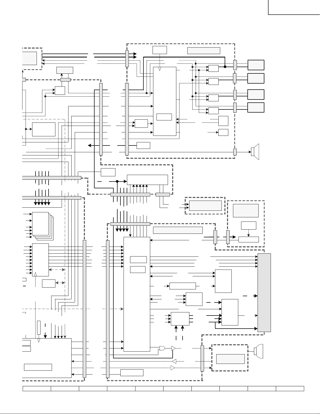
PG-M25X
9
UNIT
Reg.
2.5V,3.3V
5V,12VM
F ,L_CLICK,R_CLICK
,S-
BU5V
IC 2002
13V
BU6V
PCON 0
PCON 1
EB
Reset
FANERROR
FANPOW
FAN4
F4
KY
TH3001
Temp.
12VM
FAN 1 VCC
FANERR
FANPOW
AG_CLK
AG_DATA
RS232C/RF
L_CLICK
R_CLICK
PLUGGED
R/C
TXD2,RXD2
FANCONT1
BU5V
S+,S-
KY
FB
IC2005
SW
Reg.
BU5V
IC 3101
Motor Controller
IC2001
Sub-MCU
7.38MHz
M
Reg.
6V
2.5V5V3.3V
R/C
SCL,SDA
RST_SYS
TXD2,RXD2
TXD1,RXD1
TEMP2
KEY UNIT
FAN
CONT2
FAN
CONT3
KEY3,2,1,0 (Analog)
POW
LED(STBY,POW,
LAMPG,LAMPR.TEMP)
Reg.
Reg.
Reg.
Reg.
KEY
LED
F1
FAN1
F2
FAN2
FAN3
F3
F5
FAN5
S
CWY[3..1]
12VM
5V
2.5V
3.3V
S,
IC8319~
E
IC8322
SDRAM
A1
0]
0:3]
31]
K
IC 8029
GA4
:0]
:0]
Panel
9:0]
Controler
:0]
:0]
:0]
T
IC 8003
2
E
PROM
CLKIN
VSYNCZ
HSYNCZ
ACTDATA
BU[9:0]
GY[9:0]
RV[9:0]
FAN_1_VCC
MTRSIDI
MTRSIDO
FB
100MHz
SYSTEM
60MHz
OUTPUT
IC 9003
DLP
MTRCLK
MTRSICLK
MTRSICSZ
TM
MTRRSTZ
Data Processor
IN1IN2/RGBSEL
MHz
KHz
Main-MCU(SH3)
132.7MHz(Core)
GA4_RST
RESET
IC 8007
1.9V
RST_SYS
TXD1,RXD1
TXD2,RXD2
SCL,SDA
TEMP2
DDP_SDA
FA
DDP_SCL
PWRGOOD
RESETZ
DDP_LIGHT
LAMP_POW
FA
N_LIGHT
ECO
TEMP1
DDP1000
ASIC
TH 9003 Temp.
CWCTR
DMD FORMAT UNIT
RQ[7:0],RQB[7:0]
PCLKM
SCLKM
50MHz
VRSTEN
VBIASEN
VCC2EN
FLAD[19:0]
FLD[15:0]
Control(5 wired)
Clock Generator
IC 9005
Voltage
Generator
5V
CWINDEX
DQA[8:0]
IC 9001
IC 9004
FLASH
CONTROL(10)
12V
LAMPEN
LAMPLIT
Color Wheel
DD[63:0]
DCLK (60MHz)
LOADB_LZ,TRC_L
Serial Bus(4 wired)
CTM
CTMN
400MHz
5V
VRST -26V
VBIAS +23~+26V
VCC2+7.5V
D
5V
CW
IC 9006
RDRAM
128Mbit
IC9507
Phase
BALLAST
CW
Reset
Driver
ASIC
SENSOR
UNIT
Photo
Sensor
Comparator
3.3V
MBSRT
[15:0]
+7.5V
DMD
99
1716 1918151413121110
Page 100
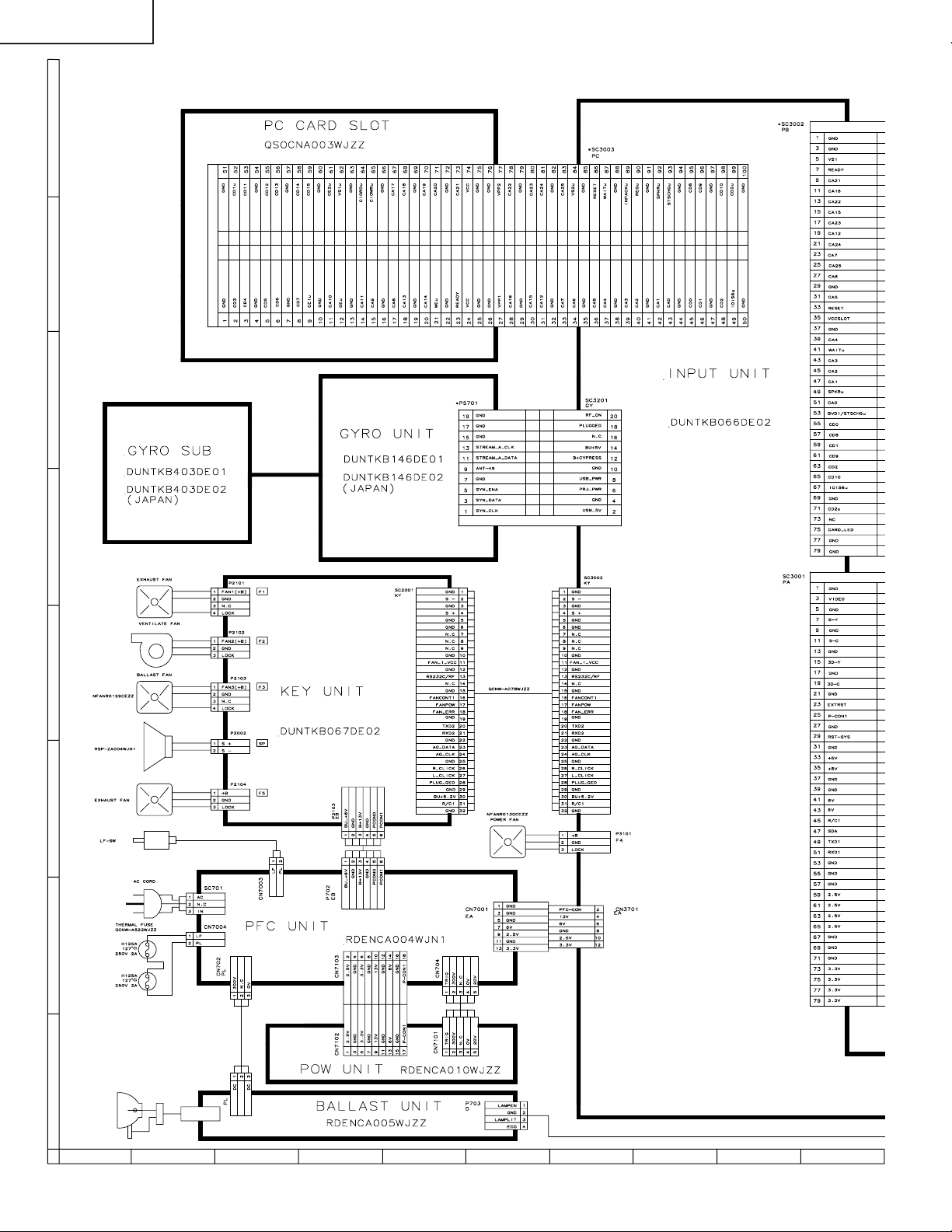
PG-M25X
O VERALL WIRING DIAGRAM/GESAMTSCHALTPLAN
H
G
F
E
D
C
B
A
87109654321
100
 Loading...