

Page 1
TENTATIVE
SERVICE MANUAL
SERVICE-ANLEITUNG
DIGITAL MULTIMEDIA PROJECTOR
DIGITALER MULTIMEDIA PROJEKTOR
MODEL
PG-M20X
MODELLE
In the interests of user-safety (Required by safety regulations in some countries) the set should be restored
to its original condition and only parts identical to those specified should be used.
Im lnteresse der Benutzersicherheit (erforderliche Sicherheitsregeln in einigen Ländern) muß das Gerät in seinen
Originalzustand gebracht werden. Außerdem dürfen für die spezifizierten Bauteile nur identische Teile verwendet
werden.
CONTENTS
Page
» SPECIFICATIONS ............................................. 2
» IMPORTANT SERVICE SAFETY
NOTES (for USA)............................................... 3
» NOTE TO SERVICE PERSONNEL ................... 4
» OPERATION MANUAL ...................................... 7
» REMOVING OF MAJOR PARTS ..................... 13
» RESETTING THE TO TAL LAMP TIMER ......... 16
» ELECTRICAL ADJUSTMENT........................... 19
» TROUBLE SHOOTING TABLE ........................ 25
» CHASSIS LAYOUT .......................................... 46
» BLOCK DIAGRAM........................................... 48
» OVERALL WIRING DIAGRAM ........................ 50
» SCHEMATIC DIAGRAM .................................. 52
» PRINTED WIRING BOARD ASSEMBLIES..... 98
» PARTS LIST
Ë
ELECTRICAL PARTS ................................ 103
Ë
CABINET AND MECHANICAL PARTS ..... 116
Ë
ACCESSORIES PARTS ............................ 120
Ë
PACKING PARTS....................................... 120
» PACKING OF THE SET ................................. 121
PG-M20X
SHARP CORPORATION
This document has been published to be used for
after sales service only.
The contents are subject to change without notice.
Page 2

PG-M20X
Specifications
Product type
Model
Video system
Display method
DMD panel
Lens
Projection lamp
Component input signal
(INPUT1)
Horizontal resolution
Computer RGB input signal
(INPUT 1)
S-video input signal
(INPUT 2)
Video input signal
(INPUT 3)
Pixel clock
Vertical frequency
Horizontal frequency
Audio input signal
Audio output
Speaker system
Rated voltage
Input current
Rated frequency
Power consumption
Power dissipation
Operating temperature
Storage temperature
Cabinet
I/R carrier frequency
Dimensions (approx.)
Weight (approx.)
Supplied accessories
Replacement parts
Digital Multimedia Projector
PG-M20X
NTSC 3.58/NTSC 4.43/PAL/PAL-M/PAL-N/PAL 60/SECAM/
DTV480I/DTV480P/DTV720P/DTV1080I
Single Chip Digital Micromirror Device™ (DMD™) by Texas Instruments
Panel size: 0.7" (17.8 mm), 1 chip XGA DMD
No. of dots: 786,432 dots (1,024 [H] × 768 [V])
1–1.2 × zoom lens, F1.75–2.04, f = 28.0–33.5 mm
High Intensity Discharge Lamp (HID Lamp), DC 210 W
29-pin connector
DVI input signal:Digital 250–1,000 mV 50 Ω
Y: 1.0 Vp-p, sync negative, 75 Ω terminated
: 0.7 Vp-p, 75 Ω terminated
P
B
: 0.7 Vp-p, 75 Ω terminated
P
R
700 TV lines (DTV720P)
29-pin connector
RGB separate/sync on green type analog input: 0–0.7 Vp-p, positive, 75 Ω terminated
HORIZONTAL SYNC. SIGNAL: TTL level (positive/negative)
VERTICAL SYNC. SIGNAL: Same as above
4-pin Mini DIN connector
Y (luminance signal): 1.0 Vp-p, sync negative, 75 Ω terminated
C (chrominance signal): Burst 0.286 Vp-p, 75 Ω terminated
RCA connector: VIDEO, composite video, 1.0 Vp-p, sync negative, 75 Ω
terminated
12–230 MHz
43–100 Hz
15–126 kHz
ø3.5 mm M
2.0 W (monaural)
4 cm × 3 cm
AC 100–240 V
3.2 A
50/60 Hz
290 W
<1,090 BTU/hour
41°F to 95°F (+5°C to +35°C)
–4°F to 140°F (–20°C to +60°C)
Plastic
38 kHz
5
⁄8" × 3" × 11 15⁄16" (219 (W) × 76 (H) × 303 (D) mm) (main body only)
8
3
8
⁄4" × 3 1⁄4" × 12 1⁄2" (223 (W) × 83 (H) × 318 (D) mm) (including adjustment feet
and projecting parts)
5.8 lbs. (2.6 kg)
Remote control, Two R-03 batteries, Power cord for U.S., Canada etc. (6', 1.8 m), Power
cord for Europe, except U.K. (6', 1.8 m), Power cord for U.K., Hong Kong and Singapore (6',
1.8 m), Power cord for Australia, New Zealand and Oceania (6', 1.8 m), DVI to 15-pin D-sub
cable (6', 1.8 m), USB cable (6', 1.8 m), Carrying case, Lens cap (attached), Lens cap
strap, Terminal cover (attached), CD-ROM, Operation manual, Quick reference guides
Lamp unit (Lamp/cage module) (BQC-PGM20X//1), Remote control (RRMCGA013WJSA),
Two R-03 batteries (“AAA” size, UM/SUM-4, HP-16, or similar), Power cord for U.S., Canada
etc. (QACCDA007WJPZ), Power cord for Europe, except U.K. (QACCV4002CEZZ), Power
cord for U.K., Hong Kong and Singapore (QACCB5024CENA), Power cord for Australia,
New Zealand and Oceania (QACCL3022CEZZ), DVI to 15-pin D-sub cable
(QCNWGA010WJZZ), USB cable (QCNWG0001WJPZ), Carrying case
(GCASN0005CESA), Lens cap (CCAPHA001WJ01), Lens cap strap (UBNDT0013CEZZ),
Terminal cover (GCOVD0103CESA), CD-ROM (UDSKA0058CEN1), Operation manual
(TINS-7609CEZZ), Quick reference guides
Analog 0.7 Vp-p 75 Ω
INIJACK
: AUDIO, 0.5 Vrms, more than 47 kΩ (stereo)
This SHARP projector uses a DMD panel. This very sophisticated panel contains 786,432 pixels. As with any high technology electronic equipment such as large screen TVs, video
systems and video cameras, there are certain acceptable
tolerances that the equipment must conform to.
Specifications are subject to change without notice.
This unit has some inactive pixels within acceptable tolerances which may result in inactive dots on the picture screen.
This will not affect the picture quality or the life expectancy
of the unit.
2
Page 3
PG-M20X
2
2
IMPORTANT SERVICE SAFETY NOTES (for USA)
Ë Service work should be performed only by qualified service technicians who are
thoroughly familiar with all safety checks and servicing guidelines as follows:
WARNING
1. For continued safety, no modification of any circuit
should be attempted.
2. Disconnect AC power before servicing.
BEFORE RETURNING THE PROJECTOR:
(Fire & Shock Hazard)
Before returning the projector to the user, perform
the following safety checks:
1. Inspect lead wires are not pinched between the
chassis and other metal parts of the projector.
2. Inspect all protective devices such as non-metallic
control knobs, insulating materials, cabinet backs,
adjustment and compartment covers or shields,
isolation resistor-capacity networks, mechanical
insulators, etc.
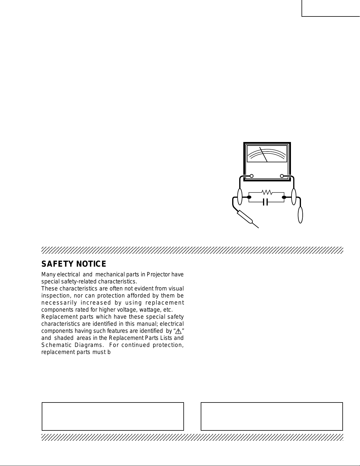
3. To be sure that no shock hazard exists, check for
current leakage in the following manner:
» Plug the AC cord directly into a 120-volt AC outlet,
(Do not use an isolation transformer for this test).
» Using two clip leads, connect a 1.5k ohm, 10 watt
resistor paralleled by a 0.15µF capacitor in parallel
between all exposed metal cabinet parts and earth
ground.
» Use an AC voltmeter with sensitivity of 5000 ohm
per volt., or higher, sensitivity to measure the AC
voltage drop across the resistor (See Diagram).
» All checks must be repeated with the AC plug
connection reversed. (If necessary, a non-polarized
adapter plug must be used only for the purpose of
completing these checks.)
Any reading of 0.3 volts RMS (this corresponds to
0.2 milliamp. A C .) or more is e xcessiv e and indicates
a potential shock hazard which must be corrected
before returning the unit to the owner.
AC
VOLTMETER
1.5k ohm (10W)
0.15µF
TEST PROBE
TO EXPOSED
METAL PARTS
CONNECT TO KNOWN
EARTH GROUND
234567890123456789012345678901212345678901234567890123456789012123456789012345678901234567890121
SAFETY NOTICE
Many electrical and mechanical parts in Projector have
special safety-related characteristics.
These characteristics are often not evident from visual
inspection, nor can protection afforded by them be
necessarily increased by using replacement
components rated for higher voltage, wattage, etc.
Replacement parts which have these special safety
characteristics are identified in this manual; electrical
components having such features are identified by “å”
and shaded areas in the Replacement Parts Lists and
Schematic Diagrams. For continued protection,
replacement parts must be identical to those used in
the original circuit. The use of a substitute replacement
parts which do not have the same safety characteristics
as the factory recommended replacement parts shown
in this service manual, may create shock, fire or other
hazards.
AVIS POUR LA SECURITE
De nombreuses pièces, électriques et mécaniques, dans
les projecteur à présentent des caractéristiques
spéciales relatives à la sécurité, qui ne sont souvent
pas évidentes à vue.
Le degré de protection ne peut pas être nécessairement
augmentée en utilisant des pièces de remplacement
étalonnées pour haute tension, puissance, etc.
Les pièces de remplacement qui présentent ces
caractéristiques sont identifiées dans ce manuel;
les pièces électriques qui présentent ces particularités
sont identifiées par la marque “å” et hachurées dans
la liste des pièces de remplacement et les diagrammes
schématiques. Pour assurer la protection, ces pièces
doivent être identiques à celles utilisées dans le circuit
d’origine. L’utilisation de pièces qui n’ont pas les mêmes
caractéristiques que les pièces recommandées par
l’usine, indiquées dans ce manuel, peut provoquer des
électrocutions, incendies ou autres accidents.
WARNING: The bimetallic component has the primary
conductive side exposed. Be very careful in
handling this component when the power is on.
234567890123456789012345678901212345678901234567890123456789012123456789012345678901234567890121
AVERTISSEMENT:La composante bimétallique dispose du
conducteur primaire dénudé. Faire
attention lors de la manipulation de cette
composante sous tension.
3
Page 4
PG-M20X
NOTE TO SERVICE
PERSONNEL
UV-RADIATION PRECAUTION
The light source, metal halide lamp, in the pr ojector
emits small amounts of UV-Radiation.
AVOID DIRECT EYE AND SKIN EXPOSURE.
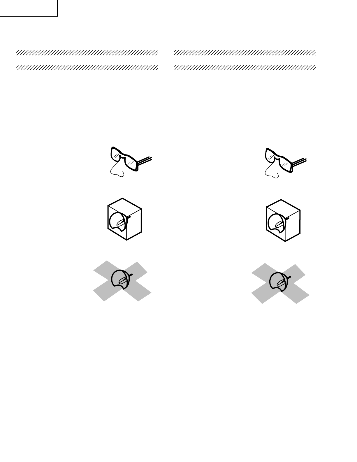
To ensure safety please adhere to the following:
1. Be sure to wear sun-glasses when servicing the
projector with the lamp
turned “on” and the top
enclosure removed.
2. Do not operate the lamp outside of the lamp housing.
NO TE POUR LE PERSONNEL
D’ENTRETIEN
PRECAUTION POUR LES RADIATIONS UV
La source de lumière, la lampe métal halide,
dans le projecteur émet de petites quantités de
radiation UV.
EVITEZ TOUTE EXPOSITION DIRECTE
DES YEUX ET DE LA PEAU.
Pour v otre sécurité, nous vous prions de respecter
les points suivants:
1. Toujours por ter des lunettes de soleil lors d’un
entretien du projecteur
avec la lampe allumée
et le haut du coffret retiré.
2. Ne pas faire fonctionner la lampe à l’extérieur du
boîtier de lampe.
3. Do not operate for more than 2 hours with the
enclosure removed.
UV-Radiation and Medium Pressure
Lamp Precautions
1. Be sure to disconnect the AC plug when replacing
the lamp.
2. Allow one hour for the unit to cool down before
servicing.
3. Replace only with same type lamp. Type BQCPGM20X//1 rated 85V/210W.
4. The lamp emits small amounts of UV-Radiation,
avoid direct-eye contact.
5. The medium pressure lamp involves a risk of
explosion. Be sure to follow installation instructions
described below and handle the lamp with care.
3. Ne pas faire fonctionner plus de 2 heures avec le
coffret retiré.
Précautions pour les radiations UV
et la lampe moyenne pression
1. Toujours débrancher la fiche AC lors du
remplacement de la lampe.
2. Laisser l’unité refroidir pendant une heure avant de
procéder à l’entretien.
3. Ne remplacer qu’avec une lampe du même type.
Type BQC-PGM20X//1 caractéristique 85V/210W.
4. La lampe émet de petites quantités de radiation UVéviter tout contact direct avec les yeux.
5. La lampe moyenne pression implique un risque
d’explosion. Toujours suivre les instructions
d’installation décrites ci-dessous et manipuler la
lampe avec soin.
4
Page 5
PG-M20X
4
5
UV-RADIATION PRECAUTION (Continued)
23456789012345678901234567890121234567890123
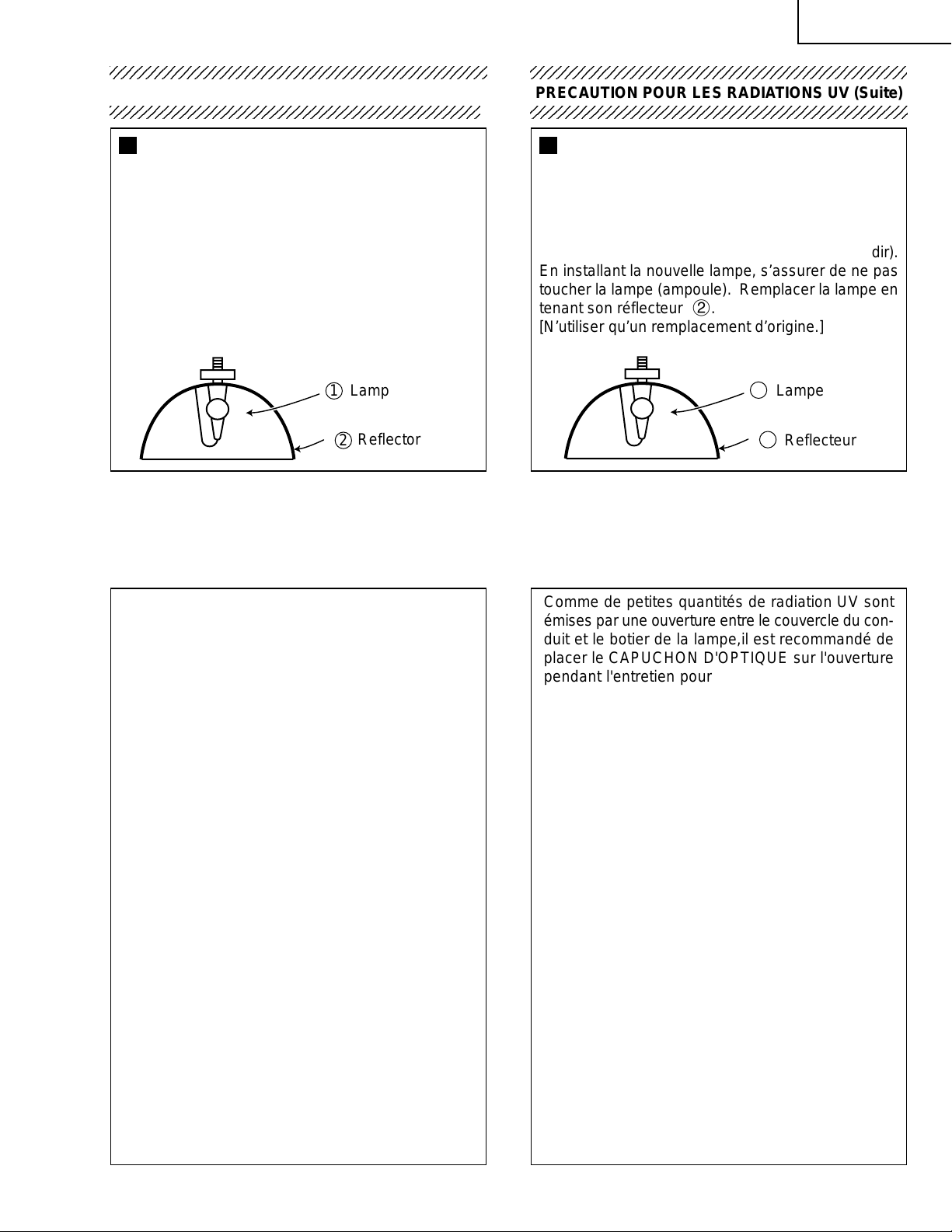
Lamp Replacement
Note:
Since the lamp reaches a very high temperature
during units operation replacement of the lamp
should be done at least one hour after the power
has been turned off. (to allow the lamp to cool off.)
Installing the new lamp, make sure not to touch the
lamp (bulb) replace the lamp by holding its reflector
2.
[Use original replacement only.]
Lamp
1
Reflector
2
DANGER ! –– Ne ver turn the power on without the
lamp to avoid electric-shock or damage of the
devices since the stabilizer generates high v oltages
at its start.
PRECAUTION POUR LES RADIATIONS UV (Suite)
234567890123456789012345678901212345678901234
Remplacement de la lampe
Remarque:
Comme la lampe devient très chaude pendant le
fonctionnement de l’unité, son remplacement ne doit
être effectué au moins une heure après avoir coupé
l’alimentation (pour permettre à la lampe de refroidir).
En installant la nouvelle lampe, s’assurer de ne pas
toucher la lampe (ampoule). Remplacer la lampe en
tenant son réflecteur 2.
[N’utiliser qu’un remplacement d’origine.]
1
Lampe
2
Reflecteur
DANGER ! –– Ne jamais mettre sous tension sans
la lampe pour éviter un choc électrique ou des
dommages des appareils car le stabilisateur génère
de hautes tensions à sa mise en route.
Since small amounts of UV-Radiation are emitted
from an opening between the duct cover and the
lamp housing, it is recommended to place the LENS
CAP on the opening during servicing to avoid eye
and skin exposure (Fig. 1).
Note: Please obtain a lens cap before servicing a
models PG-M20X that is received without
one.
Comme de petites quantités de radiation UV sont
émises par une ouverture entre le couvercle du conduit et le botier de la lampe,il est recommandé de
placer le CAPUCHON D'OPTIQUE sur l'ouverture
pendant l'entretien pour éviter une exposition des
yeux et la peau (Fig. 1).
Remarque: Priére de se procurer un capuchon
d'optique acant d'entretien un modéle
PG-M20X qui est livré sans.
Figure 1.
Figure 1.
5
Page 6

PG-M20X
WARNING: High brightness light source, do not stare into the beam of light, or view directl y . Be especially
careful that children do not stare directly in to the beam of light.
WARNING: TO REDUCE THE RISK OF FIRE OR ELECTRIC SHOCK, DO NOT EXPOSE THIS UNIT TO
MOISTURE OR WET LOCATIONS.
CAUTION
RISK OF ELECTRIC SHOCK.
DO NOT REMO VE SCREWS
EXCEPT SPECIFIED USER
SERVICE SCREWS
CAUTION: TO REDUCE THE RISK OF ELECTRIC SHOCK,
DO NOT REMO VE CABINET.
NO USER-SERVICEABLE PARTS EXCEPT LAMP UNIT.
REFER SERVICING T O QU ALIFIED SERVICE
PERSONNEL.
The lighting flash with arrowhead within
a triangle is intended to tell the user that
parts inside the product are risk of electric
shock to persons.
The exclamation point within a triangle is
intended to tell the user that important
operating and servicing instructions are
in the manual with the projector.
AVERTISSEMENT: Sour ce lumineuse de grande intensité. Ne pas fixer le faisceau lumineux ou le regar der
directement. Veiller particulièrement à éviter que les enfants ne fixent directement le
faisceau lumineux.
A VERTISSEMENT : AFIN D’EVITER T OUT RISQ UE D’INCENDIE OU D’ELECTR OCUTION, NE PAS PLACER
CET APPAREIL DANS UN ENDROIT HUMIDE OU MOUILLE.
ATTENTION
RISQUE
D’ELECTR OCUTION NE
PASRETIRER LES VIS, A
L’EXCEPTION DES VIS DE
REPARATION UTILISATEUR
SPECIFIEES
ATTENTION: POUR EVITER TOUT RISQ UE
D’ELECTR OCUTION, NE PAS RETIRER LE CAPOT.
AUCUNE DES PIECES INTERIEURES N’EST REPARABLE
PAR L ’UTILISATEUR, A L’EXCEPTION DE L’UNITE DE
LAMPE. POUR T OUTE REPARATION, S’ADRESSER A UN
TECHNICIEN D’ENTRETIEN QUALIFIE.
L’éclair terminé d’une flèche à l’intérieur
d’un triangle indique à l’utilisateur que les
pi‘eces se trouvant dans l’appareil sont
susceptibles de provoquer une décharge
électrique.
Le point d’exclamation à l’intérieur d’un
triangle indique à l’utilisateur que les
instructions de fonctionnement et
d’entretien sont détaillées dans les
documents fournis avec le projecteur.
6
Page 7
PG-M20X
Precautions for using lead-free solder
1 Employing lead-free solder
"Main PWB" of this model employs lead-free solder . The LF symbol indicates lead-free solder, and is attached on the
PWBs and service manuals. The alphabetical character following LF shows the type of lead-free solder.
Example:
L Fa
Indicates lead-free solder of tin, silver and copper.
2 Using lead-free wire solder
When fixing the PWB soldered with the lead-free solder, apply lead-free wire solder. Repairing with conventional
lead wire solder may cause damage or accident due to cracks.
As the melting point of lead-free solder (Sn-Ag-Cu) is higher than the lead wire solder by 40ºC, we recommend y ou
to use a dedicated soldering bit, if you are not familiar with how to obtain lead-free wire solder or soldening bit,
contact our service station or service ranch in your area.
3 Soldering
As the melting point of lead-free solder (Sn-Ag-Cu) is about 220ºC which is higher than the conventional lead solder
by 40ºC, and as it has poor solder wettabillty, you may be apt to keep the soldering bit in contact with the PWB for
extended period of time. However, Since the land ma y be peeled off or the maxim um heat-resistance temperature of
parts may be excoeded, remove the bit from the PWB as soon as you conurm the steady soldering condition.
Lead-free solder contains more tin, and the end of the soldering bit may be easily corroded. Make sure to tum on and
off the power of the bit as required.
if a different type of solder stays on the tip of the soldering bit, it is alloyed with lead-free solder. Clean the bit after
every use of it.
When the tip of the soldering bit is blackened during use, file it with steel wool or fine sandpaper.
Becareful when replacing parts with polarity indication on the PWB silk.
Lead-free wire solder for servicing
Part No. ★ Description Code
ZHNDAi123250E J φ0.3mm 250g(1roll) BL
ZHNDAi126500E J φ0.6mm 500g(1roll) BK
ZHNDAi12801KE J φ1.0mm 1kg(1roll) BM
7
Page 8
PG-M20X
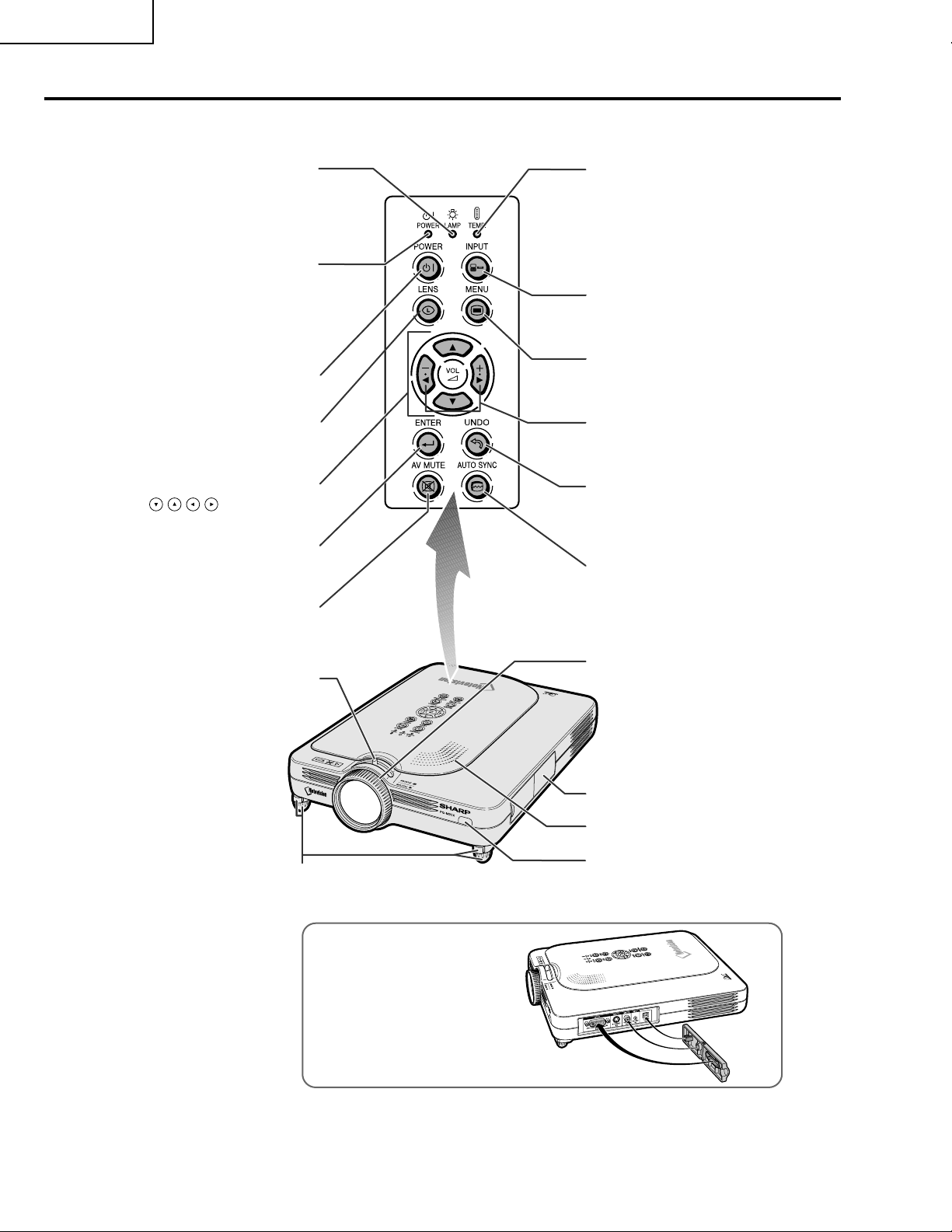
Location of Controls
Projector (Front and Top View)
LAMP REPLACEMENT
indicator
Illuminates in green normally.
Replace the lamp when the
indicator illuminates in red.
POWER indicator
Illuminates in red, when the
projector is in standby.
When the power is turned
on, this indicator will
illuminate in green.
POWER button
Turns the power on or off.
LENS button
For adjusting Keystone or
Digital Shift setting.
Adjustment buttons
(
For selecting menu items.
)
ENTER button
For setting items selected
or adjusted on the menu.
AV MUTE button
For temporarily turning off the
sound and picture.
Zoom knob
TEMPERATURE
WARNING indicator
Illuminates in green
normally. When the
internal temperature
rises, this indicator will
illuminate in red.
INPUT button
For switching input mode
1, 2 or 3.
MENU button
For displaying adjustment
and setting screens.
VOLUME buttons
For adjusting the
speaker sound level.
UNDO button
For undoing an operation
or returning to the default
settings.
AUTO SYNC button
For automatically
adjusting images when
connected to a computer.
Focus ring
Foot releases/Adjustment
feet
For adjusting the projector’s
height.
Terminal cover
Speaker
Remote control
sensor
Attaching the terminal cover
Attach the terminal cover by
placing it on the side panel of the
projector and pressing it into
place, as shown in the illustration.
8
Page 9
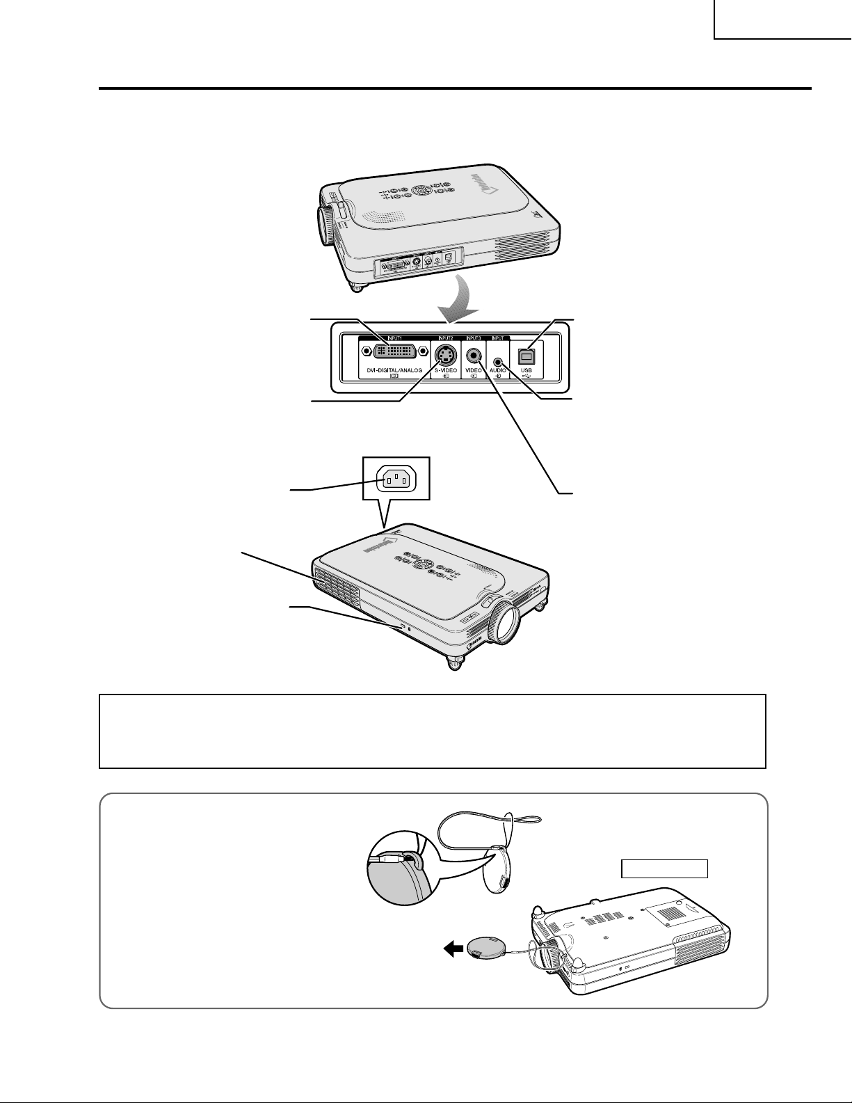
Projector (Side View)
PG-M20X
INPUT 1 terminal
Port for DVI digital, computer
RGB, and COMPONENT
signals.
INPUT 2 terminal
Terminal for connecting video
equipment with an S-VIDEO
terminal.
AC socket
USB terminal
For connecting a computer using a USB cable.
INPUT AUDIO terminal
Shared audio terminal for
INPUT 1, INPUT 2, and
INPUT 3.
INPUT 3 terminal
For connecting video
equipment.
Exhaust vent
Kensington Security
Standard connector
Using the Kensington Lock
•
This projector has a Kensington Security Standard connector for use with a Kensington MicroSaver Security
System. Refer to the information that came with the system for instructions on how to use it to secure the
projector.
Attaching the lens cap
After putting the lens cap strap on the
lens cap, pass the other end of the strap
through the hole under the projector, next
to the lens, as shown in the illustration.
Bottom View
9
Page 10
PG-M20X
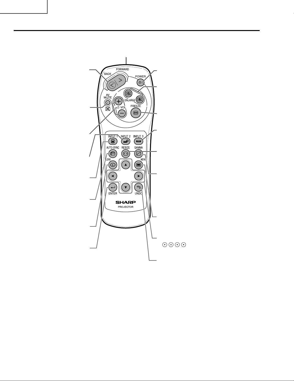
Remote Control
Remote control signal transmitter
FORWARD/BACK button
Moves forward or backwards
when connected to a computer
using a USB cable. Same as the
[Page Down] and [Page Up]
keys on a computer keyboard.
AV MUTE button
For temporarily turning off the
sound and picture.
VOLUME buttons
For adjusting the speaker
sound level.
INPUT 2 button
For switching the input mode to
INPUT 2.
INPUT 1 button
For switching the input mode to
INPUT 1.
AUTO SYNC button
For automatically adjusting
images when connected to a
computer.
LENS button
For adjusting Keystone or
Digital Shift setting.
ENTER button
For setting items selected or
adjusted on the menu.
POWER button
Turns the power on or off.
ENLARGE (Enlarge/Reduce)
buttons
For enlarging or reducing part of the
image.
FREEZE button
For freezing images.
INPUT 3 button
For switching the input mode to
INPUT 3.
RESIZE button
For switching the screen size
(NORMAL, BORDER, etc).
GAMMA button
For correcting the brightness of an
image, when the images displayed
are hard to see because of the
brightness of the room. Four
gamma modes are available to
choose from.
MENU button
For displaying adjustment and
setting screens.
Adjustment buttons
(
For selecting menu items.
)
UNDO button
For undoing an operation or
returning to the default settings.
10
Page 11
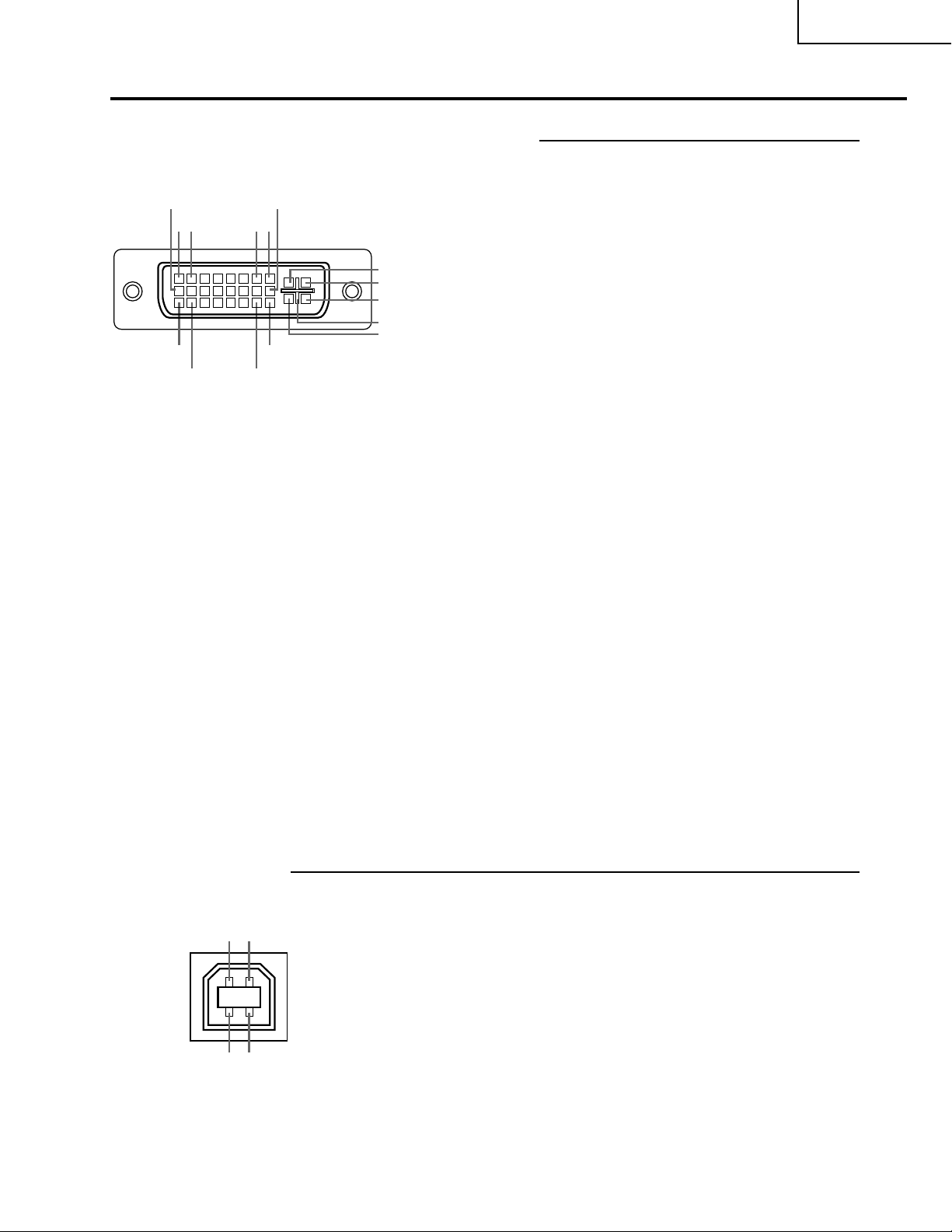
Connection Pin Assignments
DVI Digital / Analog INPUT 1 port : 29 pin connector
• DVI Digital INPUT
•••••••••
9
••••
21
17
••••
18 23
~
~
~
•••••••••
••••
••••
16
87
C1
C2
C4
C5
C3
24
Pin No. Signal Pin No. Signal
10 T.M.D.S data 1+ C1 Not connected
11 T.M.D.S data 1 shield C2 Not connected
12 Not connected C3 Not connected
13 Not connected C4 Not connected
14 +5V current C5 Ground
15 Ground
PG-M20X
1 T.M.D.S data 2– 16 Hot plug detection
2 T.M.D.S data 2+ 17 T.M.D.S data 0–
3 T.M.D.S data 2 shield 18 T.M.D.S data 0+
4 Not connected 19 T.M.D.S data 0 shield
5 Not connected 20 Not connected
6 DDC clock 21 Not connected
7 DDC data 22 T.M.D.S clock shield
8 Not connected 23 T.M.D.S clock+
9 T.M.D.S data 1– 24 T.M.D.S clock–
• DVI Analog RGB Input
Pin No. Signal Pin No. Signal
1 Not connected 16 Hot plug detection
2 Not connected 17 Not connected
3 Not connected 18 Not connected
4 Not connected 19 Not connected
5 Not connected 20 Not connected
6 DDC clock 21 Not connected
7 DDC data 22 Not connected
8 Vertical sync 23 Not connected
9 Not connected 24 Not connected
10 Not connected C1 Analog input Red
11 Not connected C2 Analog input Green
12 Not connected C3 Analog input Blue
13 Not connected C4 Horizontal sync
14 +5V current C5 Ground
15 Ground
4-pin USB connector
12
• USB connector: 4 pin B-type USB connector
Pin no. Signal Name
1 VCC USB current
2 USB– USB data–
3 USB+ USB data+
4 SG Signal Ground
• DVI Analog Component Input
Pin No. Signal Pin No. Signal
1 Not connected 16 Not connected
2 Not connected 17 Not connected
3 Not connected 18 Not connected
4 Not connected 19 Not connected
5 Not connected 20 Not connected
6 Not connected 21 Not connected
7 Not connected 22 Not connected
8 Not connected 23 Not connected
9 Not connected 24 Not connected
10 Not connected C1 Analog input Pr/Cr
11 Not connected C2 Analog input Y
12 Not connected C3 Analog input Pb/Cb
13 Not connected C4 Not connected
14 Not connected C5 Ground
15 Ground
43
11
Page 12
PG-M20X
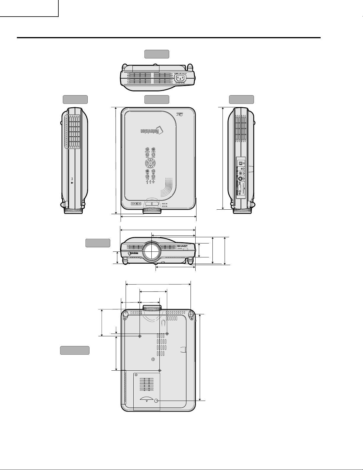
Dimensions
Side View Side ViewTop View
Rear View
12
(318.3)
Front View
1
/
8
3
(80)
9
/
16
3
1
(34.2)
5
/
16
(7.5)
1115/
16
(302.5)
3
/4 (223)
8
5
8
/8 (219)
1
5
/16 (128)
1
1
/
2
/
8
9
4
/16 (115.5)
11
7
/16 (195)
1
3
/4 (82.5)
3
2
(55.5)
3
2
/
(60)
8
/
16
(38.7)
3
(76.1)
1
3
(82.9)
/
4
Bottom View
1
4
(104)
/
8
5
10
/
(261.5)
16
Units: inches (mm)
12
Page 13

REMOVING OF MAJOR PARTS
1. Removal of the top body
1-1. Detach the terminal block cover.
1-2. Remove the five lock screws from the top body.
1-3. Slightly lift the front of the top body and disconnect the speaker connector.
2. Removal of the power PWB unit and cooling fan
2-1. Disconnect the specified connectors.
2-2. Detach the cooling fan.
2-3. Remove the four lock screws from the power unit.
2-4. Remove the three lock screws from the PFC PWB.
Top body
1-2
PG-M20X
1-3
1-2
1-2
1-2
1-1
Terminal cover
1-2
2-3
Power Unit
2-1
2-4
PFC Unit
13
2-1
2-2
Cooling fan
Page 14
PG-M20X
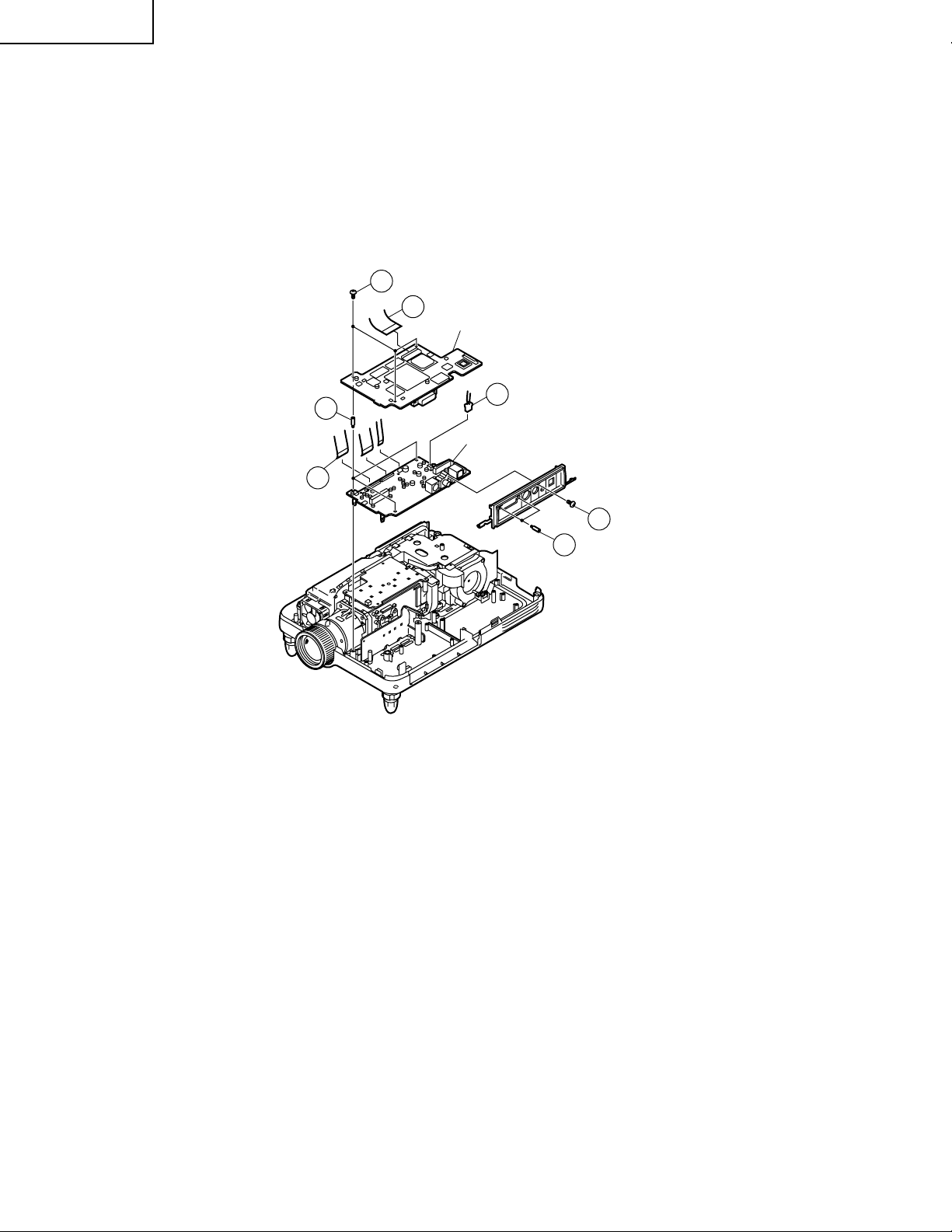
3. Removal of the PC I/F PWB and input PWB
3-1. Disconnect the specified connectors.
3-2. Remove the three lock screws and two hex screws from the PC I/F PWB.
3-3. Disconnect the connector from the input PWB.
3-4. Remove the three lock screws from the input PWB.
3-5. Remove the lock screw from the terminal block cover.
3-2
3-1
PC I/F Unit
3-3
3-4
3-3
Input Unit
3-5
3-2
14
Page 15
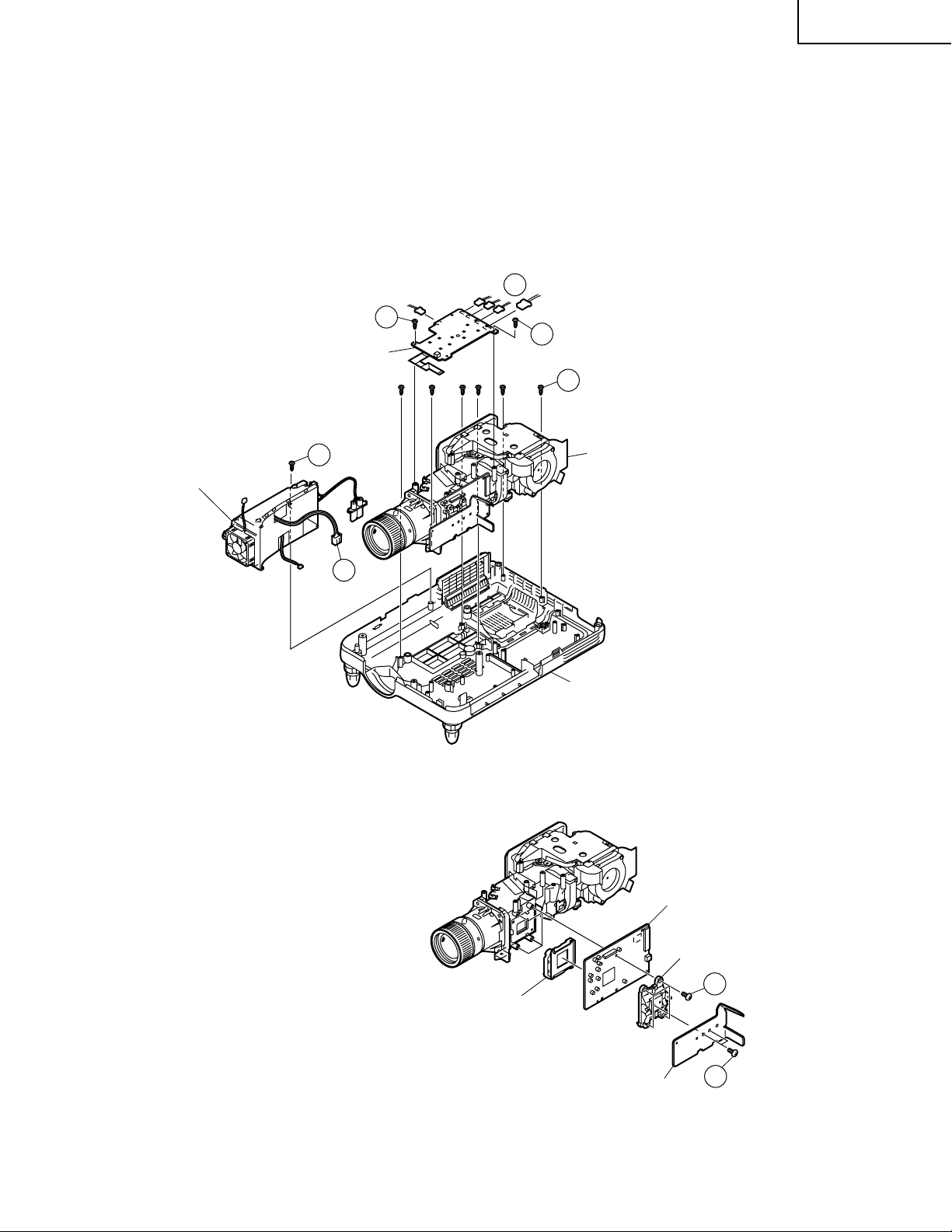
4. Removal of the operation PWB, optical unit and ballast unit
4-1. Disconnect the specified connectors from each PWB.
4-2. Remove the two lock screws from the operation PWB.
4-3. Remove the six lock screws from the optical unit.
4-4. Remove the lock screw from the ballast unit.
5. Removal of the formatter PWB
5-1. Remove the two lock screws from the heat sink.
5-2. Remove the four lock screws from the backer plate assembly, and detach the formatter PWB.
4-1
4-2
4-2
KEY Unit
4-3
PG-M20X
Ballast Unit
4-4
Optical mechanism Unit
4-1
Bottom body
Formatter Unit
DMD Unit
15
Backer plate Assy
Heat sink
5-1
5-1
Page 16
PG-M20X
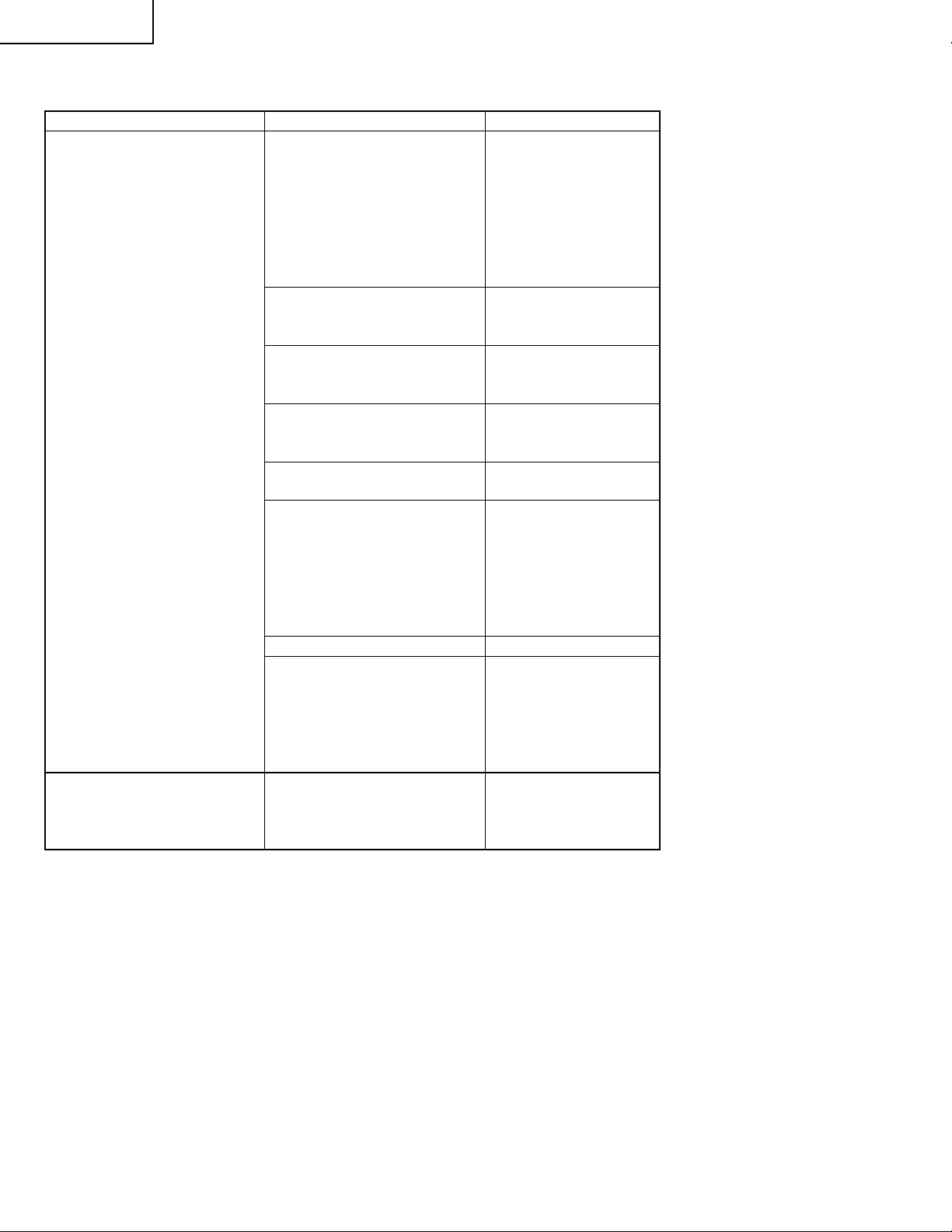
RESETTING THE TOT AL LAMP TIMER
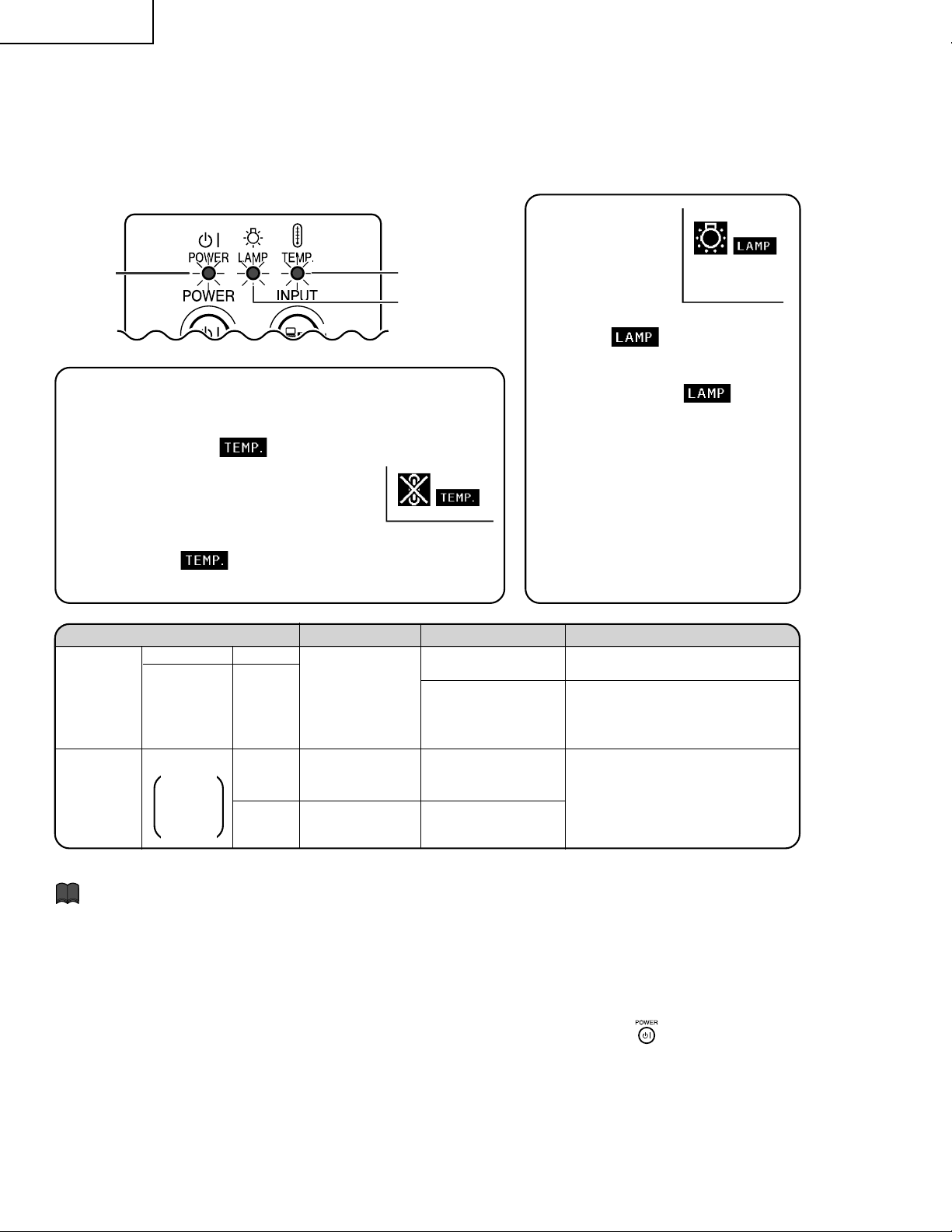
■ The warning lights on the projector indicate problems inside the projector.
■ If a problem occurs, either the TEMPERATURE WARNING indicator or the LAMP REPLACEMENT
indicator will illuminate red, and the power will turn off. After the power has been turned off, follow
the procedures given below.
About the
POWER
indicator
About the TEMPERATURE WARNING indicator
If the temperature inside the projector increases, due to blockage of the air vents, or
the setting location, “
lower left corner of the picture. If the temperature keeps on rising, the lamp will turn
off and the TEMPERATURE WARNING indicator will blink, the cooling fan will run for
further 90 seconds, then the power will be
shut off. After “
perform the following measures.
” will blink in the
” appears, be sure to
TEMPERATURE
WARNING
indicator
LAMP
REPLACEMENT
indicator
LAMP
REPLACEMENT
indicator
■When the lamp
exceeds 1,900 cumulative hours
of use, “
on the screen in yellow. When
the cumulative hours of use
reach 2,000, “
change to red, the lamp will automatically turn off and then the
projector as well. At this time , the
LAMP REPLACEMENT indicator will illuminate in red.
■If you try to turn on the projector
a fourth time without replacing
the lamp, the projector will not
turn on.
” will be displa yed
” will
Maintenance indicator Condition Problem Possible Solution
Abnormal
Red on/
Power off
Red
blinks
Red on/
Power off
The internal
temperature is
abnormally high.
Time to change
the lamp
The lamp does
not illuminate.
• Blocked air intake
• Cooling fan break-
down
• Internal circuit failure
• Clogged air intake
• Lamp usage time
exceeded 1,900
hours
• Burnt-out lamp
• Lamp circuit failure
• Relocate the projector to an area
with proper ventilation.
• Take the projector to your nearest
Sharp Authorized Projector Dealer
or Service Center for repair.
• Take the projector to your nearest
Sharp Authorized Projector Dealer
or Service Center for repair or
lamp replacement.
• Please exercise care when
replacing the lamp.
TEMPERA-
TURE
WARNING
indicator
LAMP
REPLACE-
MENT
indicator
Normal Abnormal
Off
Green on
Green
blinks
when the
lamp is
active.
Info
•If the LAMP REPLACEMENT indicator illuminates, and the power turns off, follow the above possible solutions and then wait until the projector has cooled down completely before plugging in the power cord and
turning the power back on. (At least 5 minutes.)
•If the power is turned off and then turned on again, as during a brief test, the LAMP REPLACEMENT indicator may be triggered, preventing the power from going on. Should this occur, take the power cord out of the
wall outlet and plug it back in again.
•If you want to clean the air vents during projector operation, be sure to first press
and after the power
has turned off and the cooling fan has stopped, then clean the vents.
•Do not unplug the power cord after the power has been turned off and while the cooling fan is running. The
cooling fan runs for about 90 seconds.
16
Page 17
PG-M20X
Lamp
■ It is recommended that the lamp (sold separately) be replaced after approximately 1,900 cumulative
hours of use or when you notice a significant deterioration of the picture and color quality. The
lamp usage time can be checked with the on-screen display. See page 58.
■ For lamp replacement, please consult your nearest Sharp Authorized Projector Dealer or Service
Center.
IMPORTANT NOTE TO U.S. CUSTOMERS:
The lamp included with this projector is backed by a 90-day parts and labor limited warranty. All service
of this projector under warranty, including lamp replacement, must be obtained through a Sharp Authorized Projector Dealer or Service Center. For the name of the nearest Sharp Authorized Projector Dealer
or Service Center, please call toll-free: 1-888-GO-SHARP (1-888-467-4277).
U.S.A. ONLY
Caution Concerning the Lamp
■ This projector utilizes a pressurized mercury lamp. A loud sound may indicate lamp failure. Lamp
failure can be attributed to numerous sour ces such as: excessive shock, improper cooling, surface
scratches or deterioration of the lamp due to a lapse of usage time. The period of time up to failure
largely varies depending on the individual lamp and/or the condition and the frequency of use. It is
important to note that failure can often result in the bulb cracking.
■ When the LAMP REPLACEMENT indicator and on-screen display icon are illuminated or flash, it is
recommended that the lamp be replaced with a new one immediately, even if the lamp appears to be
operating normally.
■ Should the lamp break, the glass particles may spread inside the lamp ca ge or gas contained in the
lamp may be vented into the room from the exhaust vent. Because the gas in this lamp includes
mercury, ventilate the room well if the lamp breaks and avoid all exposure to the released gas. In
case of exposure to the gas, consult with a doctor as soon as possible.
■ Should the lamp break, there is also a possibility that glass particles may spread inside of the
projector. In such a case, it is recommended you contact your nearest Sharp Authorized Projector
Dealer or Service Center to remove the damaged lamp and assure safe operation.
Replacing the Lamp
Caution
•Do not remove the lamp unit immediately after operation of the projector. The lamp will be hot and touching
it can lead to burn or injury.
•Wait at least one hour after the power cord is disconnected to allow the surface of the lamp unit to fully cool
before removing the lamp unit.
■ If the new lamp does not light after replacement, take your projector to the nearest Sharp Autho-
rized Projector Dealer or Service Center for repair. Purchase a replacement lamp unit of type BQCPGM20X//1 from your nearest Sharp Authorized Projector Dealer or Service Center. Then carefully
change the lamp by following the instructions described in this section. If you wish, you may have
the lamp replaced at your nearest Sharp Authorized Projector Dealer or Service Center.
17
Page 18

PG-M20X
How to Release the System Lock
Turn on the power. If the system lock is applied, the system-resetting screen appears. Press the following keys in this
order.
MENU → ENTER → ENTER → MENU → UNDO → UNDO → MENU
After pressing the MENU key first, press the remaining six keys within 10 seconds.
18
Page 19
ELECTRICAL ADJUSTMENT
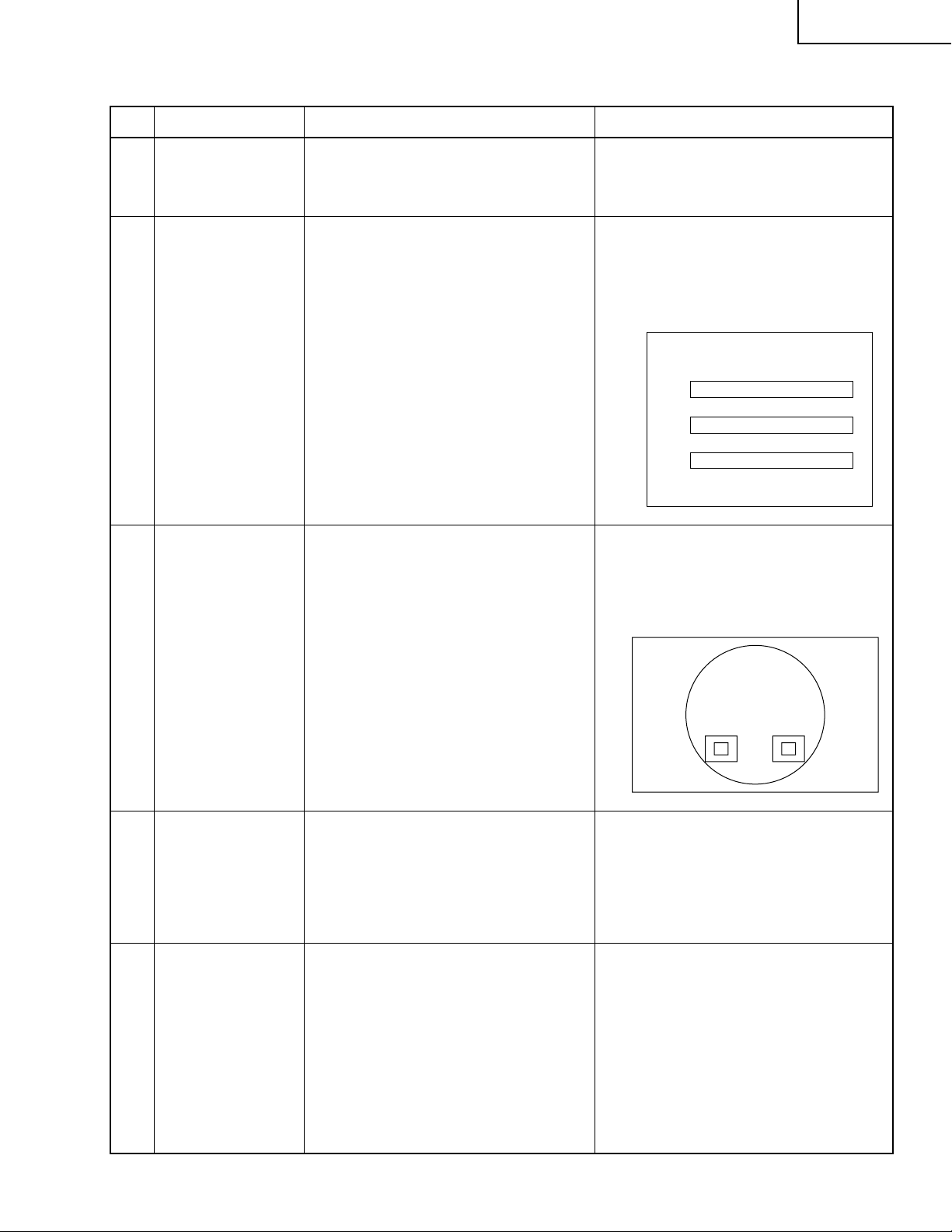
No. Adjustment Items Adjustment Conditions Adjustment Procedures
PG-M20X
1 Initialization of
EEPROM
2 Adjustment of CW
index
3 Adjustment of
RGB gradation
reproduction
1. Tur n on the power (the lamp lights
up) and warm up the system for 15
minutes.
1. Signal input: 64-step color bar
2. Select the following group and subject.
Group: DLP
Subject: Select CW-INDEX.
1. Feed the SMPTE pattern signal.
2. Select the following group and subject.
Group: DLP
Subject: G1-GAIN
1. Carry out the following setting.
Press SW2001 to enter the process
mode, and ex ecute S2 on SSS menu.
1. Feed the signal to INPUT 1.
2. Select subject and make adjustment
so that the lamp gradation patterns
of R, G and B should be smooth without noise.
R
G
B
1. Confirm that 100% and 95% white
gradation, and 0% and 5% black g r adation are discernible.
2. If the white gradation looks differently,
do fine adjustment by G1-GAIN.
4 Adjustment of
video brightness/
contrast
5 Adjustment of
video tint
1. Feed the NTSC100% window patter signal. (Burst signal)
2. Select the following group and subject.
Group: VIDEO
Subject: AUTO
1. Feed the split color bar signal.
2. Select the following group and subject.
Group: VIDEO
Subject: TINT
19
1. After signal input, select AUTO using the set's switch or the remote
controller's button for automatic adjustment.
1. Confirm the fixed value.
Fixed value: 128
Page 20

PG-M20X
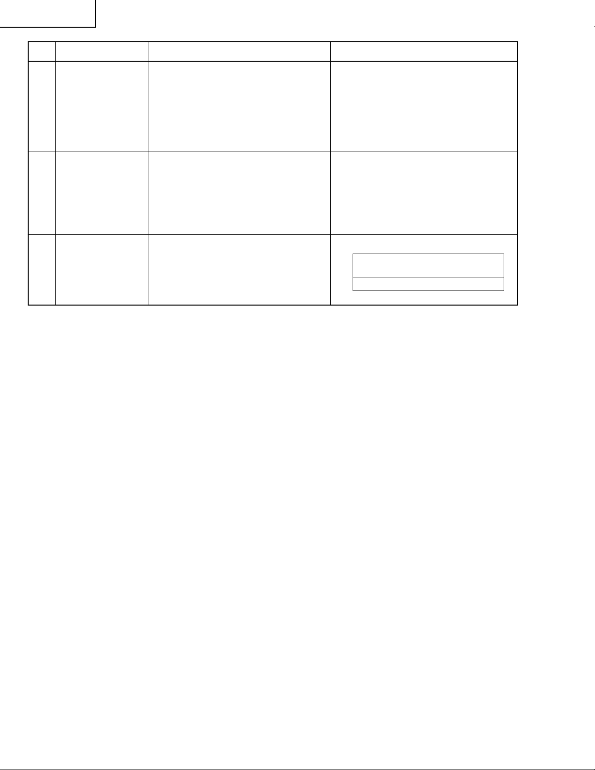
No. Adjustment Items Adjustment Conditions Adjustment Procedures
6 Adjustment of
NTSC color
saturation
7 Adjustment of PAL
color saturation
8 Adjustment of
SECAM color
saturation
9 Adjustment of
COMPO G brightness
1. Feed the internal 8ch (split color bar)
signal.
2. Select the following group and subject.
Group: VIDEO
Subject: N-COLOR
1. Feed the PAL color bar signal.
2. Select the following group and subject.
Group: VIDEO
Subject: P-COLOR
1. Feed the SECAM color bar signal.
2. Select the following group and subject.
Group: VIDEO
Subject: S-COLOR
1. Input signal: 0% gray pattern signal (480I)
2. Select the following group and subject.
Group: COMPO
Subject: G-BRIGHT
1. Confirm the fixed value.
Fixed value: 59
1. Confirm the fixed value.
Fixed value: 59
1. Confirm the fixed value.
Fixed value: 59
1. Feed the signal to INPUT 1.
Make adjustment so that some bits
should be missing in the picture.
10 Adjustment of
COMP CR-Offset
11 Automatic Adjust-
ment of RGB
white balance
12 Automatic Adjust-
ment of SRGB
white balance
1. Feed the color difference signal
(480I): Y 0% brightness, Cb and Cr
0% white patterns.
Group: COMPO
Subject: AUTO
1. Feed the 50% gray pattern signal
(XGA, 60 Hz).
2. Select the following group and subject.
Group: DLP
Subjects: R1-GAIN (Red)
B1-GAIN (Blue)
1. Feed the 50% gray pattern signal
(XGA, 60 Hz).
2. Select the following group and subject.
Group: DLP
Subjects: S-R1-GAIN (Red)
S-G1-GAIN (Green)
S-B1-GAIN (Blue)
1. After signal input, select AUTO using the set's switch or the remote
controller's button for automatic adjustment.
1. Adjust R-1 GAIN and B1-GAIN so that
x-value should be 266±3 and y-value
320±3.
1. Set the value of S-R1-GAIN to 34.
2. Adjust S-G1-GAIN and S-B1-GAIN
so that x-value should be 310±3 and
y-value 335±3.
20
Page 21

No. Adjustment Items Adjustment Conditions Adjustment Procedures
PG-M20X
13 Automatic adjust-
ment of video
white balance
14 Automatic adjust-
ment of DTV white
balance
15 Adjustment of
DLP voltage (For
reference)
16 Confirmation and
re-adjustment of
white balance
1. Feed the 50% gray pattern signal
(NTSC, burst signal).
2. Select the following group and subject.
Group: DLP
Subjects: V-R1-GAIN (Red)
V-B1-GAIN (Blue)
1. Feed the 50% gray pattern signal
(480I, color difference signal).
2. Select the following group and subject.
Group: DLP
Subjects: C-R1-GAIN
C-B1-GAIN
1. Read voltage rank of DLP description.
2. Set the switch corresponding to the
rank which has been read. (on the
formatter PWB)
1. The adjusting conditions for each
item are as follows:
For RGB input, see Item 11
For SRGB input, see Item 13
For video input, see Item 14
For DVT input, see Item 12
1. Adjust V -R1-GAIN and V-B1-GAIN so
that x-value should be 265±3 and yvalue should be 298±3.
1. Adjust C-R1-GAIN and C-B1-GAIN
so that x-value should be 263±3 and
y-value should be 295±3.
1. Carry out adjustment when DLP chip
has been replaced or combination of
chip and formatter has been changed.
2. Rank: BCDE
Setting value: 1234
Confirm that there is no deviation in white
balance from that of the monitoring
equipment.
For readjustment, proceed in the order
of RGB input, video input and DTV input.
17 Confirmation of
color-related
operation
18 Confirmation of
picture-related
operation
19 Confirmation of
RGB
20 Confirmation of
off-timer operation
21 Confirmation of
thermistor operation
1. Receive the color bar signal. 1. Select L1 in the process mode.
Check the performance of color and
tint.
1. Receive monoscope pattern signal. 1. Se lec t L2 i n th e pr ocess mode.
Check Picture, Brightness and Sharpness.
1. Receive the RGB signal. 1. Select L4 on the process mode.
Check Picture, Brightness, Red, Blue,
Clock, Phase, H-POS and V-POS.
1. Select OFF in the process mode.
Confirm that the off-timer starts with
5-minute display, counts 1 minute for
1 second, and turns off when 0 minute
is displayed.
1. Heat the thermistor by dryer. 1. Confir m that the temperature is displayed.
21
Page 22
PG-M20X
No. Adjustment Items Adjustment Conditions Adjustment Procedures
22 Automatic sync
operation
23 Confirmation of
USB operation
24 Factory settings 1. Make the following settings.
1. Receive the phase checking pattern
signal.
Connect the set to a personal computer
by USB cable.
1. Confirm that Clock, Phase, H-POS
and V-POS can be automatically
adjusted in the VGA/S-VGA/XGA
mode.
Using the remote controller, make sure
that feed and return operations are effective on the display of the personal
computer.
Process Remote controller
adjustment settings
S4 "Factory Setting 4"
How to Adjust the PC I/F unit
1. Initialization of EEPROM
1) Press SW2002 to enter the process mode.
2) Execute S1 on the SSS menu. (By S1, all the contents of EEPROM are initialized.)
3) Confirm that the program version "Ver. XXX" has become the latest one
2. Adjusting items
1) Adjustment of RGB drive/gain
(1) feed the window pattern signal that has 100% and 0% signals.
(2) Select AUTO among the A/D items in the process mode and carry out adjustment.
22
Page 23

» Adjustment mode process menu
Group Sub Group Subject
Adjust PC Image A/D R-BRIGHT
Adjust DLP Image DLP R1-BLK
Adjust VIDEO Image VIDEO PICTURE
Adjust Component Image DTV G-BRIGHT
Process mode LINE L1
INTIAL SETTING SSS TIME
Sample Pattern PATTERN RGB
PG-M20X
G-BRIGHT
B-BRIGHT
R-D
B-D
G-D
AD-AUTO
R1-GAIN
G1-BLK
G1-GAIN
B1-GAIN
CW-INDEX
S-R1-GAIN
S-G1-GAIN
S-B1-GAIN
C-R1-GAIN
C-B1-GAIN
V-R1-GAIN
V-B1-GAIN
BRIGHT
TINT
N-COLOR
P-COLOR
S-COLOR
STAT-GAIN
VIDEO-AUTO
CB-OFFSET
CR-OFFSET
COMPO-AUTO
L2
L3
OFF
TEMP OFF
SENSOR CHECK
S1
S2
S3
S4
S5
RGB(50)
CROSS
SETP
COLOR
CHR
23
Page 24
PG-M20X
Group Sub Group Subject
Adjust CVIC CVIC-PROGRSSIVE MODE
IP
MDSW
PTGSW
C-TESTSW
C-ILG-LY
C-MOD-LY
C-VE-LV
CVIC-ENHANCE-VIDE ENH-PLUS
ENH-MINUS
DFC
CVIC-ENHANCE-HTTV ENH-PLUS
ENH-MINUS
DFC
CVIC-ENHANCE-RGB ENH-PLUS
ENH-MINUS
DFC
CVIC-SCREEN CUBIC-RGB
CUBIC-VEDEO
CVIC-NR YNR-LEVEL
YNR-K
YNR-FSEL
CNR-LEVEL
CNR-K
CNR-FSEL
CNR-FILSW
CVIC-PTG TBL-NO
CVIC-CMS RED
YELLOW
GREEN
VYAN
BLUE
MAGENTA
Version Check etc Special IPL
IPL2
E2PROM
ADR RD/WR
24
Page 25
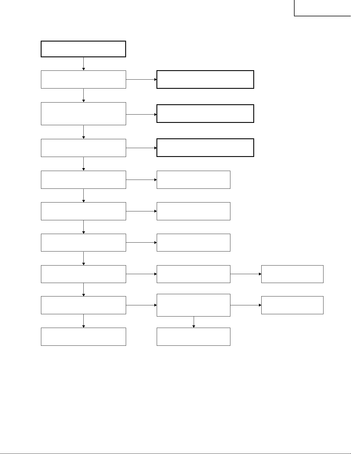
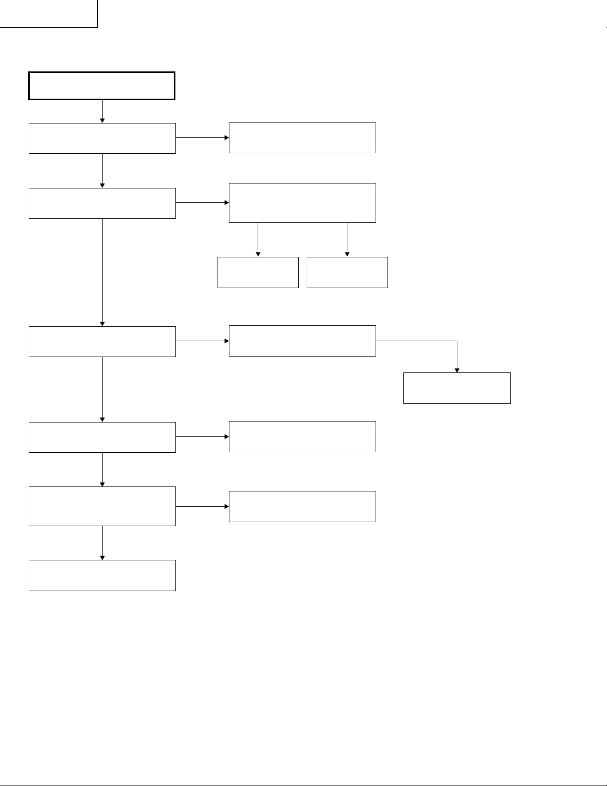
Checking of Basic Operation
PG-M20X
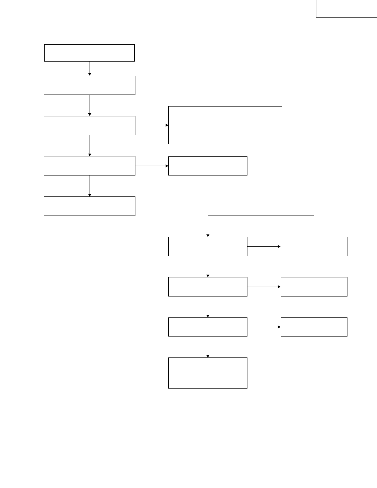
TROUBLE SHOOTING TABLE
Does the POWER LED light up or
flicker in red or green?
Yes
Does the set operate by the set's
key or the remote controller's
power key?
Yes
Does the cooling fan rotate and
does the lamp light up?
Yes
Is the user menu displayed?
Yes
Does the RGB input operate
normally?
Yes
Does the video input operate
normally?
Yes
No
No
No
No
No
No
Go to "Checking of Power Unit".
Go to "Checking of Sub-microcomputer
and Its Periphery"
Go to "Checking of Lamp Lighting-up"
Check the formatter circuit and
its periphery.
Check IC8013 (AD) and go to
"Checking of RGB Input".
Check IC8015 and peripheral
circuit.
Do the component input/DVI input
operate normally?
Yes
Does the DVI input operate
normally?
Yes
End
No
No
Is there input signal at pins
(8), (17) and (23) of IC8013?
Go to "Checking of Video
Input". Is there input signal at
the emitter of Q8002?
Yes
Check IC8015 and its
peripheral circuit.
No
No
Check IC3851 and its
peripheral circuit.
Check IC3502 and its
peripheral circuit.
25
Page 26
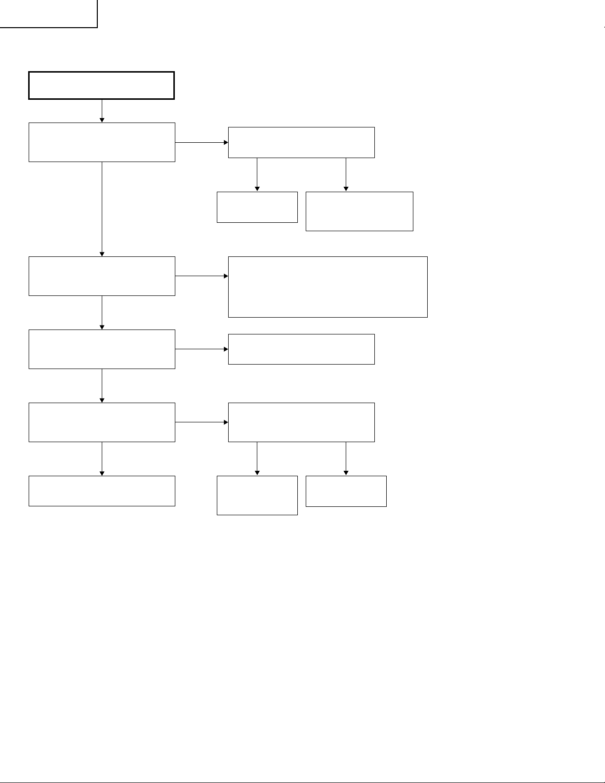
PG-M20X
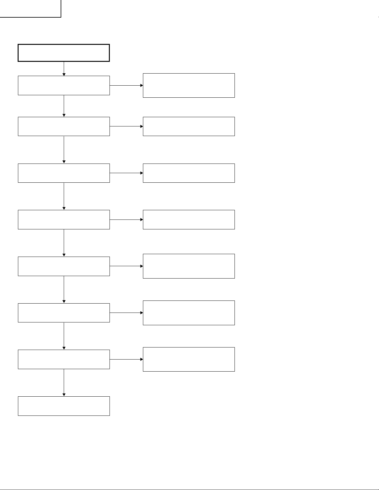
Checking of Power Unit
Are connectors in the power unit
completely inserted?
Yes
Is the lamp door closed
completely?
Yes
Is the bimetal switch turned off?
Yes
Is AC voltage applied across relay
RL7001?
Yes
No
No
No
No
Insert the connectors CN702,
CN704, CN7003, CN7001,
CN7004 and CN7101 completely.
Close the lamp door completely by
screws.
Replace the bimetal switch, or rest
it by pressing the red button.
Replace F701.
Is there DC voltage of about 6V at
pin (1) of CN7002?
Yes
Is there DC voltage of about 370V
across CN702?
Yes
Is there rated voltage at the output
terminals of CN7001 and CN7102?
Yes
Check the PWB circuits of relevant
output sides.
No
No
No
Check Q7501, Q7502 and Q7503
and their peripheral circuits. If any
circuit is damaged, replace it.
Check the circuits connected to the
primary side of T701. If any circuit
is damaged, replace it.
Check the circuits connected to the
secondary side of T701. If any
circuit is damaged, replace it.
26
Page 27
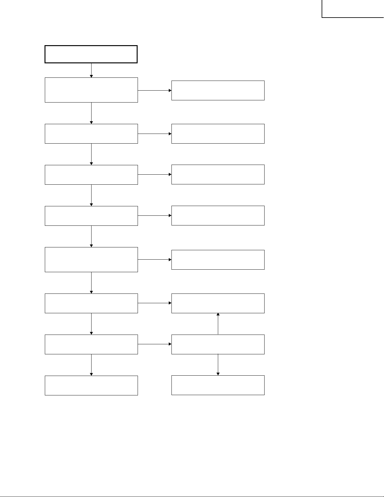
Lamp Does Not Light Up.
PG-M20X
Is any of SC9001, SC9002, P9002
and P9003 connectors
disconnected or in poor contact?
No
Is an appropriate voltage supplied
to SC9002?
Yes
Is there the 180-Hz pulse signal at
pin (1) of P9002?
No
Is the color wheel rotating?
Yes
Is there the 180-Hz pulse signal at
pin (2) of P9003 when no input
signal is given?
Yes
Yes
No
Yes
No
No
Insert the connectors completely.
Go to "Checking of Input PWB"
Go to "Checking of Lamp" and
"Checking of Ballast"
Go to "Color Wheel Does Not
Rotate."
Go to "Checking of Input PWB"
Is the signal at pin (10) of IC9101
at High level?
Yes
Is the signal at pin (9) of IC9101
at High level?
Yes
Trouble with 1C9101 or its
peripheral part.
No
No
Go to "Checking of PC I/F unit"
No
Are the signals at pins (69) and
(70) at High level?
Yes
Trouble with IC9003
27
Page 28
PG-M20X
Lamp does not light up.
Yes
Is the cooling fan rotating?
Yes
Is the color wheel rotating sound
heard?
Yes
Is the lamp discharging sound
heard?
No
No
No
Yes
Check the power circuit or the fan
circuit on the key/input PWB.
Check IC3101, the motor driver
circuit and their periphery.
Check the waveform of SC3101.
Normal Abnormal
Replace the color
wheel.
Check the socket
Check the
formatter PWB.
No
Replace the lamp.
Is DC 34V voltage applied across
the ballast power?
Yes
Is voltage higher than 3.5V applied
to pin (19) of P9002 on the
formatter PWB?
Yes
Check the ballast power.
No
No
Check the power circuit.
Check IC9101 and its periphery
on the formatter PWB.
28
Page 29
No
Yes
Does POWER LED flicker in red
(for 2 seconds)?
No
Is there B+3.3V output at pins (12)
and (13) of CN3701?
Is there 6V output at pins (5) and
(6) of P2003?
Yes
Go to "Checking of PC I/F Unit", and check
the flexible connector.
Communication error of sub-microprocessor
(KEY) and SH microprocessor (PC I/F unit)
Pins (20) and (21) of P2001.
Yes
Go to "Checking of Power Unit"
Check Q2001 thru Q2004 of
IC2001.
No
No
Yes
Is Bu+6.2V signal outputted?"
Go to "Checking of
Power Unit"
Yes
No
Is Bu+3.3V signal outputted?
Check IC2010 and its
periphery.
Check IC2002 and its
periphery.
Yes
No
Is 3.3V signal output at pin
(19) of IC2001?
Check IC2001 and its
periphery and go to
"Checking of Remote Control
Communication".
Checking of Sub-microprocessor
and Its Periphery
PG-M20X
29
Page 30
PG-M20X
Checking of Low-pass Filter Circuit
Is video signal is inputted to pins
(4), (8) and (12) of IC3851?
Yes
Is video signal inputted to pins
(24), (21) and (17) of IC3851?
Yes
Is video signal is inputted to pins
(16), (20) and (24) of SC3001?
Yes
The low-pass filter circuit on the
input PWB is normal. Does the
picture appear?
Yes
No
No
No
No
Check pins (4), (8) and (12) of
SC3001.
Normal Abnormal
Check Q3854 and
Q3855.
IC3851 is defective.
If the picture quality is abnormal, check whether
or not the following voltages are outputted to
pin (28) of IC3851.
0.3 V for 480i, 1 V for 720p, 1080i, Check IC301.
Check Q3851, Q3852 and Q3853
and their periphery.
Is the video signal inputted to pins
(8), (17) and (23) of IC8013
(AD9888) of the PC I/F unit?
Yes No
Check the PC I/F unit.
Check DVI (analog)
input.
End
Check the SOG
circuit or IC8013
and its periphery.
30
Check IC8013
and its periphery.
Page 31

Feed the 480i component signal in INPUT 1.
Select INPUT 1 using the set's key or the remote controller.
Select 480i among the special modes on the user
menu screen.
Is 480i selected among the special
modes?
Does the contour of picture
appear clear.
Confirmation of synchronization.
Is Y signal including sync signal
inputted to pin (3) of IC2502?
Is picture outputted?
Is the color normal?
No
Is the signal type set to the
component?
In case of monitor output,
disconnect the monitor output
cable.
Set the monitor output.
Check the monitor output
equipment and cable.
No
Yes
Yes
No
Yes
Yes No
Yes
Abnormal
No
Set the signal type.
IC8025 is defective. Select 480i.
Restored to normal condition
Yes
End
Checking of DTV
(480i Component Input)
Check IC8016
(Video decoder).
Go to "Checking of
Low-pass Filter Circuit"
Check IC3501 and its
periphery.
Yes
No
PG-M20X
31
Page 32

PG-M20X
Checking of Video Input
Feed the composite video signal to
INPUT 3. Select INPUT 3 using the
set's key or the remote controller.
Does the picture appear?
No No
Is the video signal including sync
signal inputted to pin (3) of SC3001
on the input PWB?
No
Is the video signal including sync
signal inputted to pin (7) of SC3502
on the input PWB?
No
Yes Yes
Yes
Yes
Is the picture disturbed?
1
Check IC8016 (video decoder)
of PC board and its periphery.
Check Q8002.
Check Q3512 and Q3513 on
the input PWB.
Are pin(5) (horizontal) and
pin(10) (vertical) signals
inputted to IC8363 on the
PC I/F unit?
No
Check IC8363 and
IC8025 (CVIC2) and
their periphery.
1
Yes
Check IC3502 and its peripheral
circuit.
No
Feed the S-video signal to INPUT 2.
Select INPUT 2 using the set's key
or the remote controller. Does the
picture appear?
Yes
Is the color normal?
Yes
End
No
32
Yes
Is the C signal inputted
to pin (11) of SC3001?
No
Check Q3502 on the
input PWB.
Page 33

» FORMATTER Unit
PG-M20X
Abnormal picture
Rainbow-like picture
Go to "Lamp Does Not
Light Up."
Is signal outputted at
pins (3), (5) and (7) of
SC9001?
Yes
Trouble with IC9003,
IC9006 or their periphery
Is any of SC9001, SC9002, P9002
and P9003 connectors
disconnected or in poor contact?
Is an appropriate voltage supplied
to SC9002?
No
No
Yes
Blackout
No
No Yes
Yes
No
Is the lamp on?
Go to "Checking of PC I/F nunit"
Insert the connectors
completely.
Go to "Checking of Input PWB"
Others
Reassemble the DMD, optical
mechanism and formatter unit.
Is the symptom improved?
No
Is the voltage at the positive-polarity
pin of C9066 appropriate (+7V)?
Yes
Is the voltage at the positive-polarity
pin of C9068 appropriate (+23 to +26V)?
Yes
Is the voltage at the negative-polarity
pin of C9562 appropriate (-26V)?
Yes
Trouble with the DMD
Yes
No
No
No
End
Trouble with peripheral circuit
of C9066 or trouble with IC9003
Trouble with peripheral circuit
of C9068 or trouble with IC9003
Trouble with peripheral circuit
of C9562 or trouble with IC9003
33
Page 34

PG-M20X
» PC I/F Unit-1/12
Checking of PC PWB
0
Is the user menu displayed?
No
Check the onscreen display.
Check the RGB input.
Check the component input.
Check the video input.
Yes
Check the DVI digital input.
PCカードのチェック
Check the PC card.
End
34
Page 35

» PC I/F Unit-2/12
Checking of Onscreen Display
PG-M20X
Is the user menu displayed
normally by the MENU key?
No
Enter the process menu and select
PATTERN. Then select the
COLOR pattern.
Is the onscreen display color
normal?
Yes
Make STEP signal selection.
Is the STEP signal normal?
Yes
No
Yes
The onscreen display is normal.
Adjust the DLP system in the
process adjustment mode.
0
Rewrite the onscreen display data.
No
Is the signal compatible with the
STEP signal outputted at TL106
thru TL111?
Yes
Go to "Checking of GA4 and Its
Periphery".
Rewrite the onscreen display data.
No
0
IC8025 is defective.
35
Page 36

PG-M20X
» PC I/F Unit-3/12
Checking of RGB Input
Feed the sync separation type
analog RGB signal to INPUT 1.
1
Select INPUT 1 using the set's
key or the remote controller.
2
Does the picture appear?
Is the picture disturbed?
3
Do the three colors R, G and B
appear?
Carry out the AUTOSYNC process.
Is the contour of picture clear?
Yes
No
Yes
No
Yes
No
No
Go to "Confirmation of
Video Input".
Go to "Checking of Sync Signal".
Go to "Checking of RGB Signal".
Yes
Is there any disturbance in the
vertical stripe pattern?
No
End
Yes
IC8013, 8025 or its periphery is
defective.
36
Page 37

» PC I/F Unit-4/12
Confirmation of Video Input
Make "Confirmation of Input
Signal Setting".
PG-M20X
Is there video signal at the land
of C8070?
Yes
Go to "Checking of Sync Signal".
IC8025 or IC8013 is defective.
Confirmation of Input Signal Setting
Is the input menu selected
correctly?
Yes
No
No
Is there signal at the terminal C2 of
P8001 (DVI connector)?
Yes
Somewhere in the signal route is
defective. Check the capacitors and
resistors between the connector
and IC8013.
The signal source or connector
is defective.
Select the input menu correctly.
No
Are the connectors connected
correctly?
Yes
End
No
2
Connect the connectors correctly.
1
37
Page 38

PG-M20X
» PC I/F Unit-5/12
Checking of Sync Signal
Is there the vertical sync signal at
pin (11) of IC8363?
Yes
Is there the horizontal sync signal
at pin (5) of IC8363?
Yes
Is there the vertical sync signal at
TL8131?
Yes
Is there the horizontal sync signal
at TL8130?
Yes
No
No
No
No
Make confirmation of input signal
setting.
IC8330, IC8331 or its periphery
is defective.
IC8363 is defective.
Are both the vertical and horizontal
signals in appropriate timing?
No
Is the signal generator
(input source) appropriate?
Yes
IC8330, IC8331 or its periphery
is defective.
Yes
No
The sync signal is normal.
End of checking.
Set the signal source appropriately.
2
38
Page 39

» PC I/F Unit-6/12
Checking of R, G and B Signals
PG-M20X
Is the signal type set to RGB?
Yes
Set the process mode.
Select R, G and B individually on
the pattern menu.
Go to "Checking of GA4 and Its
Periphery".
For checking the input signal,
set the signal generator to
gradation signal.
No
Set the signal type to RGB.
Check TL8169, TL8170 and
TL8180 by oscilloscope.
(MSB bit after A/D conversion)
Are there the specified signals at
TL8169, TL8170 and TL8180?
Yes
IC8025 and its periphery are
defective.
No
Does the signal come to C8062,
C8070 and C8078?
Yes
IC8013 and its periphery are
defective.
No
Go to "Confirmation of
Video Input".
39
Page 40

PG-M20X
» PC I/F Unit-7/12
Checking of GA4 and Its Periphery
Select R, G and B individually on
the pattern menu in process mode.
Is picture outputted appropriately
in R, G and B?
No
Check pins (72), (52) and (32) of
SC8001 by oscilloscope.
These signals are MSB of B/G/R.
Do the signals selected on the
pattern menu match with those
checked by oscilloscope?
No
Does the clock signal come to pin
(78) of SC8001?
Yes
Yes
Yes
No
Checking of GA4 and its periphery
ends.
The DLP PWB is defective.
Is there the clock (32.5 MHz)
signal at TL8114?
No
Is there the clock (32.5 MHz)
signal at TL8110?
Yes
Yes
IC8029 is defective.
No
X8005 is defective.
Check TL8106, TL8107, TL8108,
TL8109, TL81010 and TL81011
by oscilloscope.
Do the signals selected on the
pattern menu match with those
checked by oscilloscope?
Yes
IC8029 is defective.
IC8025 is defective.
No
IC8025 is defective.
40
Page 41

» PC I/F Unit-8/12
Checking of Component Input
Feed the component signal to
INPUT 1.
Select INPUT 1 using the set's
key or the remote controller.
PG-M20X
(except 480I)
Is the picture appear?
Yes
4
Is the color normal?
No
Is the signal type set at component?
Yes
Carry out the process adjustment.
4
No
No
Go to "Checking of SOG Circuit".
Set the signal type to component.
Is the contour of picture clear?
Yes
The component is normal. End.
No
IC8013 or IC8025 is defective.
41
Page 42

PG-M20X
» PC I/F Unit-9/12
Checking of SOG Circuit
Check pin (2) of IC8365 by
oscilloscope.
Is the composite sync signal
reproduced in correct timing?
No
Check the land of C8070 by
oscilloscope.
Is there the Y signal including sync
signal?
Yes
The SOG sync separation circuit
(input PWB) is defective.
Yes
No
The SOG circuit is normal.
End.
Go to "Confirmation of Input
Signal Setting".
42
Page 43

Feed the composite video signal to
INPUT 3.
Select INPUT 3 using the set's key
or the remote controller.
Is there any disturbance in the
picture?
The video input is normal. End.
Is the color normal?
Is the picture appear?
Go to "Checking of Video
Sync Signal".
No
Yes
Input PWB is defective.
Q8003 and its periphery are
defective.
IC8015 is defective.
No
Is there the specified signal
at R114?
No
5
5
No
Checking of Video Input
Go to "Checking of Video
Sync Signal".
Carry out the process
adjustment.
Yes
No
Yes
Check the clock signal of IC8015
by FL8114.
Is the clock signal normal?
Yes
IC8025 and its periphery are
defective.
Yes
Yes
Is the video signal inputted to
C8141?
No
Go to "Checking of Video Sync
Signal".
» PC I/F Unit-10/12
PG-M20X
43
Page 44

PG-M20X
» PC I/F Unit-11/12
Checking of Video Sync Signal
Check pin (10) of IC8363 by
oscilloscope.
(Checking of vertical sync signal)
Is the vertical sync signal normal?
Yes
Check pin (6) of IC8363 by
oscilloscope.
(Checking of horizontal sync signal)
Is the horizontal sync signal
normal?
Yes
Are the horizontal sync signal and
vertical sync signal outputted at
TL8130 and TL8131?
Yes
Is there the specified clock
(13.5 MHz) signal at FL114?
Yes
No
No
No
No
Go to "Confirmation of Input Signal
Setting".
IC8015 and its periphery are
defective.
IC8015 and its periphery are
defective.
End
44
Page 45

» PC I/F Unit-12/12
Checking of DVI Digital Input
Feed the DVI digital signal to
INPUT 1.
Select INPUT 1 for input.
PG-M20X
Is the picture appear?
Yes
Is there any disturbance in the
picture?
Yes
Is the color normal?
Yes
The DVI digital input is normal.
Check pin (13) of IC8363 for vertical
sync signal, and check pin (3) of
IC8363 for horizontal sync signal.
No
No
No
IC8298 and its periphery are
defective.
Are the sync signals normal?
Yes
Check R8685 for clock signal.
Is the clock signal normal?
Yes
IC8025 and its periphery are
defective.
No
No
IC8298 and its periphery are
defective.
45
Page 46

CHASSIS LAYOUT
H
G
F
PG-M20X
E
D
C
B
A
121110987654321
46
47
Page 47

BLOCK DIAGRAM
PG-M20X
H
G
F
E
D
C
B
A
Rod Antenna
Filter
WIRED R/C
AUDIO-IN
S-Video
PCMCIA TYPE II Card
802.11b SS W-LAN
FLASH ATA
MEMORY
IC 5801
FM Receiver
RF-DATA
GYRO UNIT
USB
Video
VIDEO
INPUT UNIT
DVI
DVI
or
Filter
455kHz
IC 5803
Packet Flaming
PIC
A
UDIO
IC 3502
SW
S-C
S-Y
R/C
PC-BOARD
R,G,B
IC8330~IC8331
Comparator
IC8011
2
PROM
E
RX2+,RX2RX1+,RX1RX0+,RX0RXC+,RXC-
PC
Card
Slot
IC8298
3.3VC
Panel
Link
Reg.
G
H,V
Reg.
Reg.
D+,D-
IC 3851
LPF
R,G,B
SI_H,V
IC 3301
Audio AMP
LPF720P
G
DTVR,G,B
CN2
CARDVCC
RF_ON
ANT_49
GY
PLUGGED
BU+5V
USB_5V
S/VIDEO
S/COMP
IC 3901~3
SOG
Sync sep.
IC 8363
CD[15:0]
CA[25:0]
CONTROL
VCC3VEN
GY
GSYNC
SW
DTVR,G,B
PODCK
IN1IN2/RGBSEL
CN2
SYN_ENE,DATA,CLK
STREAM_A_CLK,DATA
STATUS,USB_PWR
B+CYPRESS
VOL
S+,S-
S-Y
S-C
VIDEO
VIDEO
S-C
VH,VV
IC 8013
A/D
Amp
D[15:0]
IC8002
Card Slot
Interface
A[23:0]
PLL
CPU BUS(65.5MHz)
CTL
R,G,B
PDE
IC 8015
Digital
Video
Decoder
24.576MHz
GSYNC
PCH,PCV
AD_SCL
AD_SDA
MEMR
MEMW
SYSCK
WAIT_CARD
IC 3201
USB-Controller
(CYPRESS)
6MHz
LEARN
AG_MENU
VOL
S/VIDEO
S/COMP
LPF720P
SOGSEL
AGCLK,AGDATA
CN
1
CN
1
VY[8]
VUV[8]
ITLC
VAO
VCLK
VH,VV
S
W
G
GPEN,GCLP,GCOAST
GHS2
GCLK
GRO[7:0],GRE[7:0]
GGO[7:0],GGE[7:0]
BE[7:0]
[7:0],G
BO
G
SH3-Bus Bridge
PDE
IC8028 IC8030
SDRAM
4M×(16+16)
D[31:0]
RD,WE1
IC8367
SCLI,SCLO,SDAI,SDAO
IRQ5,10,14
CTL
A[23:0]
CKIO
DDP_SCL,DDP_SCL
SCL
SDA
IC3002
DAC
PCON1
Reg. 1.9V,1.8V
32.5MHz
25MHz
IC 8025
OE
WE
WAIT
CVIC 2
IC 8005
FLASH
4M×16bit
SYNR
H
AD_SCL,AD_SDA
IC 3202
2
PROM
E
D[15:0]
A[23:0]
A[23:0]
D[15:0]
FANCONT1
PCON1
TXD1,RXD1
PLUGGED
CTL
CTL
POWER UNIT
EA
2.5V6V3.3V
13V
PFCCON
CONT4
FAN
OW
FANP
RS232C/RF ,L_CLICK,R_CLICK
S+,S-
RST_SYS
CLK
CS,RAS,
CAS,WE
BA1,BA1
A[0:10]
DQM[0:3]
DQ[0:31]
DCLK
DVS
DHS
DRO[9:0]
DRE[9:0]
DGO[9:0]
DGE[9:0]
DBO[9:0]
DBE[9:0]
RESET
1.8V,3.3V
A[23:0]
D[15:0]
16.58MHz
32.768KHz
CTL
IN1IN2/RGBSEL
132.7MHz(Core)
IC8319~
SDRAM
Controler
Main-MCU(SH3)
Reg.
2.5V,3.3V
5V,12VM
BU5V
IC8322
IC 8029
GA4
Panel
IC 8003
E
GA4_RST
RESET
IC 8007
2.5V5V3.3V
2
PROM
1.9V
6V
RST_SYS
FAN4
F4
Reg.
R/C
SCL,SDA
SCL,SDA
TXD1,RXD1
TEMP2
TXD2,RXD2
RST_SYS
TXD2,RXD2
TXD1,RXD1
TEMP2
13V
BU6V
PCON 0
PCON 1
VSYNCZ
HSYNCZ
ACTDATA
BU[9:0]
GY[9:0]
RV[9:0]
DDP_SDA
FA
DDP_SCL
PWRGOOD
RESETZ
DDP_LIGHT
LAMP_POW
N_LIGHT
CLKIN
ECO
TEMP1
KY
TH3001
Temp.
12VM
FAN 1 VCC
FANERR
FANPOW
AG_CLK
AG_DATA
RS232C/RF
L_CLICK
R_CLICK
PLUGGED
R/C
TXD2,RXD2
FANCONT1
BU5V
S+,S-
FAN_1_VCC
FA
EB
KY
FB
12VM
5V
2.5V
3.3V
MTRSIDO
FB
IC 9003
Data Processor
DDP1000
TH 9003 Temp.
IC2005
SW
Motor Controller
MTRSIDI
MTRSICLK
100MHz
SYSTEM
60MHz
OUTPUT
TM
DLP
ASIC
Reg.
BU5V
IC 3101
MTRCLK
MTRRSTZ
MTRSICSZ
IC 2002
Reset
FANERROR
FANPOW
FAN
CONT2
IC2001
Sub-MCU
7.38MHz
M
CWY[3..1]
CWCTR
FAN
CONT3
KEY3,2,1,0 (Analog)
LED(STBY,POW,
LAMPG,LAMPR.TEMP)
DMD FORMAT UNIT
CWINDEX
DQA[8:0]
RQ[7:0],RQB[7:0]
PCLKM
SCLKM
50MHz
FLAD[19:0]
FLD[15:0]
Control(5 wired)
VRSTEN
VBIASEN
VCC2EN
IC 9001
Clock Generator
IC 9004
FLASH
CONTROL(10)
IC 9005
Voltage
Generator
12V
5V
LAMPEN
LAMPLIT
KEY UNIT
Reg.
Reg.
Reg.
Reg.
POW
Color Wheel
DD[63:0]
DCLK (60MHz)
LOADB_LZ,TRC_L
Serial Bus(4 wired)
CTM
CTMN
400MHz
5V
VRST -26V
VBIAS +23~+26V
VCC2+7.5V
D
KEY
LED
5V
CW
IC 9006
RDRAM
128Mbit
IC9507
BALLAST
CW
Phase
Reset
Driver
ASIC
F1
F2
F3
F5
S
SENSOR
UNIT
Photo
Sensor
Comparator
MBSRT
[15:0]
FAN1
FAN2
FAN3
FAN5
3.3V
+7.5V
DMD
48
121110987654321
49
Page 48

O VERALL WIRING DIAGRAM
H
G
F
PG-M20X
E
D
C
B
A
121110987654321
50
51
Page 49

PG-M20X
DESCRIPTION OF SCHEMATIC
DIAGRAM
VOLTAGE MEASUREMENT CONDITION:
1. Voltages at test points are measured at the supply
voltage of AC 230V. Signals are fed by a colour bar
signal generator for servicing purpose and the above
voltages are measured with a 20k ohm/V tester.
WAVEFORM MEASUREMENT CONDITION:
1. Wavef orms at test points are observed at the supply
voltage of AC 230V. Signals are fed by a colour bar
signal generator for servicing purpose.
INDICATION OF RESISTOR & CAPACITOR:
RESISTOR
1. The unit of resistance “Ω” is omitted.
(K=kΩ=1000 Ω, M=MΩ).
2. All resistors are ± 5%, unless otherwise noted.
(J= ± 5%, F= ± 1%, D= ± 0.5%)
3. All resistors are 1/16W, unless otherwise noted.
4. All resistors are Carbon type, unless otherwise
noted.
C : Solid
S : Oxide Film T : Special
N : Metal Coating
CAPACITOR
1. All capacitors are µF, unless otherwise noted.
(P=pF=µµF).
2. All capacitors are 50V, unless otherwise noted.
3. All capacitors are Ceramic type, unless otherwise
noted.
(ML): Mylar (TA): Tantalum
(PF): Polypro Film (ST): Styrol
CAUTION:
This circuit diagram is original one, therefore there may be a
slight difference from yours.
SAFETY NOTES:
1. DISCONNECT THE AC PLUG FROM THE AC
OUTLET BEFORE REPLACEING PARTS.
2. SEMICONDUCTOR HEAT SINKS SHOULD BE
REGARDED AS POTENTIAL SHOCK HAZARDS
WHEN THE CHASSIS IS OPERATING.
IMPORTANT SAFETY NOTICE:
PARTS MARKED WITH “ å ( ) ARE
IMPORTANT FOR MAINTAINING THE SAFETY OF
THE SET. BE SURE TO REPLACE THESE PARTS
WITH SPECIFIED ONES FOR MAINTAINING THE
SAFETY AND PERFORMANCE OF THE SET.
W
: Cement
BESCHREIBUNG DES
SCHEMATISCHEN SCHALTPLANS
SPANNUNGSMESSUNGEN:
1. Spannungen an den Prüfpunkten werden bei einer
Netzspannung von 230V gemessen, Signale werden
für die Wartung mit einem Farbbalken-Signal
generator zugeführt, und Spannungen werden mit
einem Meßinstrument (20 kΩ/V) ermittelt.
SIGNALFORMMESSUNGEN:
1. Die Wellenformen an den Testpunkten werden bei
einer Netzspannung von 230V verfolgt. Signale
werden für die W artung mit einem Farbbalk en-Signal
generator zugeführt.
BEZEICHNUNG DES WIDERSTANDS UND
KONDENSATORS:
WIDERSTAND
1. Die Widerstandseinheit “Ω” wird weggelassen.
(K=kΩ=1000 Ω, M=MΩ).
2. Alle Widerstände haben ± 5%, sofern nicht anders
angegeben.
(J= ± 5%, F= ± 1%, D= ± 0.5%)
3. Alle Widerstände haben 1/16W, sofern nicht anders
angegeben.
4. Alle Widerstände sind Kohletyp, sofern nicht anders
angegeben.
C : Fest
S : Oxidefilm T : Spezial
N : Metallüberzug
KONDENSATOR
1. Die Kapazitätseinheit ist µF, sofern nicht anders
angegeben.
(P=pF=µµF).
2. Alle Kondensatoren haben 50V, sofern nicht anders
angegeben.
3. Alle Kondensatoren sind Keramiktyp, sofer n nicht
anders angegeben.
(ML): Mylar (TA): Tantal
(PF): Polyprofilm (ST): Styrol
ACHTUNG:
bei diesem Schaltplan handelt es sich um den ursprünglichen.
Esönnen daher geringfügige Unterschiede zu dem lhrem bestehen.
SICHERHEITSANMERKUNGEN:
1. VOR DEM AUSWECHSELN VON TEILEN MUSS
UNBEDINGT NETZSTECKER AUS DER
NETZSTECKDOSE GEZOGEN WERDEN.
2. DIE WARMEABLEITER DER HALBLEITER SOLLTEN
BEIM BETRIEB DES CHASSIS ALS MÖGLICHE
URSACHEN VON GEFÄHRLICHEN ELEKTRISCHEN
SCHLÄGEN BETRACHTET WERDEN.
WICHTIGE SICHERHEITSANMERKUNGEN:
MIT “å ( )BEZEICHNETEN TEILE SIND
BESONDERS WICHTIG FÜR DIE A UFRECHTERHALTUNG
DER SICHERHEIT . BEIM WECHDIESER TEILE SOLLTEN
DIE VORGESCHRIEBENEN TEILE IMMER VERWENDET
WERDEN, UM SO W OHL DIE SICHERHEIT ALS AUCH DIE
LEISTUNG DES GERÄTES AUFRECHTZUERHALTEN.
W
: Zement
52
Page 50

WAVEFORMS
PG-M20X
1 SC3101 1-pin
(INPUT CWCTR)
H : 200µ sec/div
V : 6.90V/div
5 SC9001 3-pin
(FORMAT CLKIN)
H : 400µ sec/div
V : 870mV/div
9 SC9002 25-pin
(FORMAT MTRCLK)
H : 40m sec/div
V : 1.44V/div
2 SC3101 3-pin
(INPUT CWY2)
H : 200µ sec/div
V : 6.90V/div
6 SC9001 5-pin
(FORMAT HSYNC)
H : 10µ sec/div
V : 880mV/div
0 IC8363 7-pin
(PC-BOARD PCH)
H : 10µ sec/div
V : 840mV/div
3 P9002 1-pin
(FORMAT LAMPEN)
H : 2m sec/div
V : 1.64V/div
7 SC9001 7-pin
(FORMAT VSYNC)
H : 4m sec/div
V : 880mV/div
q IC8363 1-pin
(PC-BOARD PCV)
H : 4m sec/div
V : 840mV/div
4 P9003 2-pin
(FORMAT CWINDEX)
H : 2m sec/div
V : 1.64V/div
8 SC9002 17-pin
(FORMAT MTRSICLK)
H : 2µ sec/div
V : 1.44V/div
w SC3001 3-pin
(INPUT VIDEO)
H : 10µ sec/div
V : 180mV/div
e SC3001 11-pin
(INPUT S-C)
H : 20µ sec/div
V : 1.44V/div
r SC3001 8-pin
(INPUT PCGIN2)
H : 10µ sec/div
V : 180mV/div
t SC3001 20-pin
(INPUT GLPF)
H : 10µ sec/div
V : 230mV/div
53
y SC3001 30-pin
(INPUT C-SYNC)
H : 10µ sec/div
V : 840mV/div
Page 51

PG-M20X
Ë
FORMATTER UNIT-1/5
H
G
F
E
D
C
B
A
121110987654321
54
55
Page 52

PG-M20X
Ë
FORMATTER UNIT-2/5
H
G
F
E
D
C
B
A
121110987654321
56
57
Page 53

PG-M20X
Ë
FORMATTER UNIT-3/5
H
G
F
E
D
C
B
A
121110987654321
58
59
Page 54

PG-M20X
Ë
FORMATTER UNIT-4/5
H
G
F
E
D
C
B
A
121110987654321
60
61
Page 55

PG-M20X
Ë
FORMATTER UNIT-5/5
H
G
F
E
D
C
B
A
121110987654321
62
63
Page 56

PG-M20X
Ë
INPUT UNIT-1/5
H
G
F
E
D
C
B
A
121110987654321
64
65
Page 57

PG-M20X
Ë
INPUT UNIT-2/5
H
G
F
E
D
C
B
A
121110987654321
66
67
Page 58

PG-M20X
Ë
INPUT UNIT-3/5
H
G
F
E
D
C
B
A
121110987654321
68
69
Page 59

PG-M20X
Ë
INPUT UNIT-4/5
H
G
F
E
D
C
B
A
121110987654321
70
71
Page 60

PG-M20X
Ë
INPUT UNIT-5/5
H
G
F
E
D
C
B
A
121110987654321
72
73
Page 61

PG-M20X
Ë
KEY UNIT-1/3
H
G
F
E
D
C
B
A
121110987654321
74
75
Page 62

PG-M20X
Ë
KEY UNIT-2/3
H
G
F
E
D
C
B
A
121110987654321
76
77
Page 63

PG-M20X
Ë
KEY UNIT-3/3
H
G
F
E
D
C
B
A
121110987654321
78
79
Page 64

PG-M20X
Ë
POWER UNIT
H
G
F
E
D
C
B
A
121110987654321
80
81
Page 65

PG-M20X
Ë
PFC UNIT
H
G
F
E
D
C
B
A
121110987654321
82
83
Page 66

PG-M20X
Ë
PC I/F UNIT-1/7
H
G
F
E
D
C
B
A
121110987654321
84
85
Page 67

PG-M20X
Ë
PC I/F UNIT-2/7
H
G
F
E
D
C
B
A
121110987654321
86
87
Page 68

PG-M20X
Ë
PC I/F UNIT-3/7
H
G
F
E
D
C
B
A
121110987654321
88
89
Page 69

PG-M20X
Ë
PC I/F UNIT-4/7
H
G
F
E
D
C
B
A
121110987654321
90
91
Page 70

PG-M20X
Ë
PC I/F UNIT-5/7
H
G
F
E
D
C
B
A
121110987654321
92
93
Page 71

PG-M20X
Ë
PC I/F UNIT-6/7
H
G
F
E
D
C
B
A
121110987654321
94
95
Page 72

PG-M20X
Ë
PC I/F UNIT-7/7
H
G
F
E
D
C
B
A
121110987654321
96
97
Page 73

PG-M20X
PRINTED WIRING BOARD ASSEMBLIES
H
G
F
E
D
C
B
A
PC I/F Unit (Side-A)
654321
98
Page 74

PG-M20X
H
G
F
E
D
C
B
A
PC I/F Unit (Side-B)
654321
99
Page 75

PG-M20X
H
G
F
E
D
FORMATTER Unit (Side-A)
INPUT Unit (Side-A)
C
B
A
KEY Unit (Side-A)
654321
100
Page 76

PG-M20X
H
G
F
E
D
FORMATTER Unit (Side-B)
INPUT Unit (Side-B)
C
B
A
KEY Unit (Side-B)
654321
101
Page 77

PG-M20X
H
G
F
POWER Unit (Side-A)
E
D
POWER Unit (Side-B)
C
B
A
PFC Unit (Component Side)
654321
102
Page 78

PG-M20X
Ref. No. Part No. ★ Description Code Ref. No. Part No. ★ Description Code
PARTS LIST
ERSATZTEILLISTE
PARTS REPLACEMENT
Parts marked with "å" are important for maintaining the safety of
the set. Be sure to replace these parts with specified ones for maintaining the safety and performance of the set.
"HOW TO ORDER REPLACEMENT PARTS"
To have your order filled promptly and correctly, please furnish the
following informations.
Ersatzteile, die besondere Sicherheitseigenschften haben, sind in
dieser Anleitung markiert. Elektrische Komponenten mit solchen
Eigenshaften sind in den Ersatzteil durch "å" gekenn-zeichnet.
Der Gebrauch von Ersatzteilen, die nicht deselben Sicherheitseigenschaften haben wie die vom Hersteller empfohlenen ud in der
Bedienungsanleitung angegebenen, können zur Ursache von
Blitzeinschlägen, Bränden und anderen Gefahren werden.
AUST A USCH VON TEILEN
"WIE MAN ERSATSTEILE BESTELLT"
1. MODEL NUMBER 2. REF. NO.
3. PART NO. 4. DESCRIPTION
5. CODE 6. QUANTITY
in USA: Contact your nearest SHARP Parts Distributor.
For location of SHARP Parts Distributor,
Please call Toll-Free; 1-800-BE-SHARP
in CANADA: Contact SHARP Electronics of Canada Limited
Phone (416) 890-2100.
★ MARK: SPARE PARTS-DELIVERY SECTION
Ref. No. Part No. ★ Description Code Ref. No. Part No. ★ Description Code
PRINTED WIRING BOARD ASSEMBLIES
(NOT REPLACEMENT ITEM)
DUNTKB065DE01 - Formatter Unit —
DUNTKB066DE01 - Input Unit —
DUNTKB067DE01 - Key Unit —
RDENCA004WJZZ - Power Unit —
RDENCA010WJZZ - PFC Unit —
CPCi-0057CE01 - PC I/F Unit —
RDENCA005WJZZ J Ballast Unit BZ
(Unit Replacement)
Damit Ihre Bestellung promt und korrekt ausgeführt wird, geben Sie
bitte folgende Informationen.
1. MODELL NR. 2. REF. NR.
3. ERSATZTEIL NR. 4. BESCHREIBUNG
5. KODE 6. QUANTITÄT
★ MARKIERUNG : ERSATZTEILE-LIEFERUNG
DUNTKB065DE01
FORMATTER UNIT
INTEGRATED CIRCUITS
IC9001 VHiTCDCR83D-1 J TCDCR83D
IC9003 RH-iXA089WJZZ J IC
IC9004 RH-iXA090WJZZ J IC
IC9005 VHiLT1613CS-1 J LT1613CS
IC9006 VHiK4R271S8-1 J K4R271S8
IC9007 VHiLP3962M1-1 J LP3962M1
IC9101 VHiAHCT08PW-1 J AHCT08PW
IC9504 VHiOPA237NA-1 J OPA237NA
IC9505 VHiLM321MF+-1 J LM321MF
IC9506 VHiOPA237NA-1 J OPA237NA
IC9507 RH-iXA005WJZZ J IC
IC9510 VHi4040CM35-1 J 4040CM35
IC9511 VHi4040CM35-1 J 4040CM35
Q9001 VS2SJ356+++-1 J 2SJ356
Q9002 VS2SC4672Q/-1 J 2SC4672Q AE
Q9003 VS2SC3928AR-1 J 2SC3928AR AB
Q9101 VS2SC3928AR-1 J 2SC3928AR AB
Q9102 VS2SC3928AR-1 J 2SC3928AR AB
Q9501 VSMMBT2907A-1 J MMBT2907A
Q9502 VSMMBT2907A-1 J MMBT2907A
Q9503 VSMMBT2222A-1 J MMBT2222A
Q9504 VSMMBT2907A-1 J MMBT2907A
Q9505 VSMMBT2222A-1 J MMBT2222A
Q9506 VSMMBT2907A-1 J MMBT2907A
Q9507 VSiMT17++++-1 J IMT17
Q9508 VSUMH4N++++-1 J UMH4N
Q9509 VSUMH4N++++-1 J UMH4N
Q9510 VSFDG6303N+-1 J FDG6303N
Q9511 VSFDG6303N+-1 J FDG6303N
D9005 VHDMi1A3///2E J Diode AC
DIODES AND THERMISTER
TRANSISTORS
D9006 VHDMi1A3///2E J Diode AC
D9007 VHDMi1A3///2E J Diode AC
D9008 VHDSFPA73//2E J Diode
TH9003 RH-HXA001WJZZ J Thermister AD
PACKAGED CIRCUITS AND COIL
X9001 RCRUAA001WJZZ J Crystal
103
Page 79

PG-M20X
Ref. No. Part No. ★ Description Code Ref. No. Part No. ★ Description Code
DUNTKB065DE01
FORMATTER UNIT(Continued)
X9002 RCRUAA002WJZZ J Crystal
L9001 RCiLP0191GEZZ J Peaking Coil
CAPACITOES
C9001 VCEAPF1CW106M J 10 16V Electrolytic AB
C9002 VCKYCY1EF104Z J 0.1 25V Ceramic AA
C9003 VCKYCY1EF104Z J 0.1 25V Ceramic AA
C9004 VCKYCY1EF104Z J 0.1 25V Ceramic AA
C9006 VCKYCY1EF104Z J 0.1 25V Ceramic AA
C9007 VCKYCY1EF104Z J 0.1 25V Ceramic AA
C9008 VCCCCY1HH680J J 68p 50V Ceramic AA
C9009 VCKYCY1EF104Z J 0.1 25V Ceramic AA
C9010 VCCCCY1HH680J J 68p 50V Ceramic AA
C9011 VCKYCY1EF104Z J 0.1 25V Ceramic AA
C9013 VCKYCY1EF104Z J 0.1 25V Ceramic AA
C9014 VCKYCY1EF104Z J 0.1 25V Ceramic AA
C9015 VCKYCY1EF104Z J 0.1 25V Ceramic AA
C9016 VCKYCY1EF104Z J 0.1 25V Ceramic AA
C9019 VCSNDE0GP107M J 100 4.0V
C9021 VCKYCY1EF104Z J 0.1 25V Ceramic AA
C9022 VCEAPF1CW106M J 10 16V Electrolytic AB
C9023 VCKYCY1CB104K J 0.1 16V Ceramic AB
C9024 VCCCCY1HH680J J 68p 50V Ceramic AA
C9025 VCKYCY1EF104Z J 0.1 25V Ceramic AA
C9026 VCCCCY1HH680J J 68p 50V Ceramic AA
C9027 VCKYCY1EF104Z J 0.1 25V Ceramic AA
C9028 VCEAPF1HW105M J 1.0 50V Electrolytic AB
C9029 VCKYCY1CB104K J 0.1 16V Ceramic AB
C9030 VCCCCY1HH4R0C J 4.0p 50V Ceramic AA
C9032 VCKYCY1CB104K J 0.1 16V Ceramic AB
C9034 VCKYCY1CB104K J 0.1 16V Ceramic AB
C9035 VCKYCY1EF104Z J 0.1 25V Ceramic AA
C9036 VCKYCY1EF104Z J 0.1 25V Ceramic AA
C9037 VCEASH1VN106M J 10 35V Electrolytic
C9038 VCKYCY1CB104K J 0.1 16V Ceramic AB
C9039 VCKYCY1HF104Z J 0.1 50V Ceramic
C9041 VCKYCY1CB104K J 0.1 16V Ceramic AB
C9042 VCKYCY1EF104Z J 0.1 25V Ceramic AA
C9043 VCKYCY1CB104K J 0.1 16V Ceramic AB
C9044 VCKYCY1EF104Z J 0.1 25V Ceramic AA
C9045 VCKYCY1CB104K J 0.1 16V Ceramic AB
C9046 VCEASH1VN106M J 10 35V Electrolytic
C9047 VCKYCY1HF104Z J 0.1 50V Ceramic
C9049 VCEASH1VN106M J 10 35V Electrolytic
C9050 VCKYCY1EF104Z J 0.1 25V Ceramic AA
C9051 VCKYCY1HF104Z J 0.1 50V Ceramic
C9053 VCKYCY1CB104K J 0.1 16V Ceramic AB
C9054 VCCCCY1HH7R0D J 7.0p 50V Ceramic AA
C9055 VCKYCY1EF104Z J 0.1 25V Ceramic AA
C9056 VCEAPV1EW475M J 4.7 25V Electrolytic AC
C9057 VCKYCY1CB104K J 0.1 16V Ceramic AB
C9058 VCEAPF1EW475M J 4.7 25V Electrolytic AB
C9059 VCKYCY1CB104K J 0.1 16V Ceramic AB
C9060 VCKYCY1EF104Z J 0.1 25V Ceramic AA
C9061 VCKYCY1CB104K J 0.1 16V Ceramic AB
C9062 VCKYCY1CB104K J 0.1 16V Ceramic AB
C9063 VCSNDE0GP107M J 100 4.0V
C9064 VCEAPF1HW105M J 1.0 50V Electrolytic AB
C9065 VCEAPF1CW106M J 10 16V Electrolytic AB
C9066 VCEAPF1HW335M J 3.3 50V Electrolytic AB
C9067 VCEAPF1CW106M J 10 16V Electrolytic AB
C9068 VCEAPF1HW335M J 3.3 50V Electrolytic AB
C9069 VCSNDE0GP107M J 100 4.0V
C9070 VCKYCY1HF104Z J 0.1 50V Ceramic
C9071 VCKYCY1EF104Z J 0.1 25V Ceramic AA
C9072 VCKYCY1EF104Z J 0.1 25V Ceramic AA
C9073 VCKYCY1EF104Z J 0.1 25V Ceramic AA
C9075 VCEAPF1HW105M J 1.0 50V Electrolytic AB
C9101 VCKYCY1EF104Z J 0.1 25V Ceramic AA
C9102 VCKYCY1EF104Z J 0.1 25V Ceramic AA
C9503 VCKYCY1EF104Z J 0.1 25V Ceramic AA
C9505 VCKYCY1EF104Z J 0.1 25V Ceramic AA
C9510 VCKYCY1EF104Z J 0.1 25V Ceramic AA
C9511 VCKYCY1EF104Z J 0.1 25V Ceramic AA
C9513 VCKYCY1EF104Z J 0.1 25V Ceramic AA
C9514 VCKYCY1EF104Z J 0.1 25V Ceramic AA
C9515 VCKYCY1EF104Z J 0.1 25V Ceramic AA
C9516 VCKYCY1EF104Z J 0.1 25V Ceramic AA
C9517 VCKYCY1EF104Z J 0.1 25V Ceramic AA
C9519 VCKYCY1EF104Z J 0.1 25V Ceramic AA
C9520 VCKYCY1EF104Z J 0.1 25V Ceramic AA
C9521 VCKYCY1EF104Z J 0.1 25V Ceramic AA
C9522 VCKYCY1EF104Z J 0.1 25V Ceramic AA
C9523 VCEAPF1CW106M J 10 16V Electrolytic AB
C9524 VCKYCY1EF104Z J 0.1 25V Ceramic AA
C9525 VCKYCY1EF104Z J 0.1 25V Ceramic AA
C9527 VCKYCY1HF104Z J 0.1 50V Ceramic
C9528 VCKYCY1EF104Z J 0.1 25V Ceramic AA
C9529 VCKYCY1EF104Z J 0.1 25V Ceramic AA
C9530 VCKYCY1EF104Z J 0.1 25V Ceramic AA
C9531 VCKYCY1EF104Z J 0.1 25V Ceramic AA
C9532 VCKYCY1EF104Z J 0.1 25V Ceramic AA
C9533 VCKYCY1EF104Z J 0.1 25V Ceramic AA
C9535 VCKYCY1EF104Z J 0.1 25V Ceramic AA
C9536 VCKYCY1EF104Z J 0.1 25V Ceramic AA
C9537 VCKYCY1EF104Z J 0.1 25V Ceramic AA
C9538 VCKYCY1EF104Z J 0.1 25V Ceramic AA
C9539 VCKYCY1EF104Z J 0.1 25V Ceramic AA
C9542 VCKYCY1EF104Z J 0.1 25V Ceramic AA
C9544 VCKYCY1EF104Z J 0.1 25V Ceramic AA
C9545 VCKYCY1EF104Z J 0.1 25V Ceramic AA
C9546 VCKYCY1EF104Z J 0.1 25V Ceramic AA
C9547 VCKYCY1EF104Z J 0.1 25V Ceramic AA
C9548 VCKYCY1EF104Z J 0.1 25V Ceramic AA
C9549 VCKYCY1EF104Z J 0.1 25V Ceramic AA
C9550 VCKYCY1EF104Z J 0.1 25V Ceramic AA
C9551 VCKYCY1EF104Z J 0.1 25V Ceramic AA
C9552 VCKYCY1EF104Z J 0.1 25V Ceramic AA
C9553 VCKYCY1EF104Z J 0.1 25V Ceramic AA
C9554 VCKYCY1EF104Z J 0.1 25V Ceramic AA
C9555 VCKYCY1EF104Z J 0.1 25V Ceramic AA
C9558 VCEAPF0GW227M J 220 4.0V Electrolytic AB
C9562 VCEAPF1HW335M J 3.3 50V Electrolytic AB
C9563 VCKYCY1EF104Z J 0.1 25V Ceramic AA
C9564 VCKYCY1EF104Z J 0.1 25V Ceramic AA
C9565 VCKYCY1EF104Z J 0.1 25V Ceramic AA
C9566 VCKYCY1EF104Z J 0.1 25V Ceramic AA
C9567 VCKYCY1EF104Z J 0.1 25V Ceramic AA
RESISTORS
R9001 VRS-CY1JF000J J 0 1/16W Metal Oxide AA
R9003 VRS-CY1JF103J J 10k 1/16W Metal Oxide AA
R9005 VRS-CY1JF103J J 10k 1/16W Metal Oxide AA
R9006 VRS-CY1JF111F J 110 1/16W Metal Oxide AA
R9007 VRS-CY1JF111F J 110 1/16W Metal Oxide AA
R9008 VRS-CY1JF103J J 10k 1/16W Metal Oxide AA
R9010 VRS-CY1JF560F J 56 1/16W Metal Oxide AA
R9011 VRS-CY1JF560F J 56 1/16W Metal Oxide AA
R9014 VRS-CY1JF302F J 3.0k 1/16W Metal Oxide AA
R9017 VRS-CY1JF683F J 68k 1/16W Metal Oxide AA
R9018 VRS-TV1JD240J J 24 1/16W Metal Oxide AA
R9020 VRS-CY1JF103J J 10k 1/16W Metal Oxide AA
R9031 VRS-CY1JF333J J 33k 1/16W Metal Oxide AA
R9032 VRS-CY1JF333J J 33k 1/16W Metal Oxide AA
R9101 VRS-CY1JF471J J 470 1/16W Metal Oxide AA
R9102 VRS-CY1JF182J J 1.8k 1/16W Metal Oxide AA
R9103 VRS-CY1JF472J J 4.7k 1/16W Metal Oxide AA
R9104 VRS-CY1JF471J J 470 1/16W Metal Oxide AA
R9105 VRS-CY1JF473J J 47k 1/16W Metal Oxide AA
R9106 VRS-CY1JF103J J 10k 1/16W Metal Oxide AA
R9107 VRS-CY1JF102J J 1.0k 1/16W Metal Oxide AA
R9108 VRS-CY1JF102J J 1.0k 1/16W Metal Oxide AA
R9109 VRS-CY1JF473J J 47k 1/16W Metal Oxide AA
R9110 VRS-CY1JF101J J 100 1/16W Metal Oxide AA
R9111 VRS-CY1JF101J J 100 1/16W Metal Oxide AA
R9112 VRS-CY1JF101J J 100 1/16W Metal Oxide AA
R9113 VRS-CY1JF101J J 100 1/16W Metal Oxide AA
R9114 VRS-CY1JF101J J 100 1/16W Metal Oxide AA
104
Page 80

PG-M20X
Ref. No. Part No. ★ Description Code Ref. No. Part No. ★ Description Code
DUNTKB066DE01
INPUT UNIT
R9115 VRS-CY1JF101J J 100 1/16W Metal Oxide AA
R9116 VRS-CY1JF000J J 0 1/16W Metal Oxide AA
R9118 VRS-CY1JF101J J 100 1/16W Metal Oxide AA
R9119 VRS-CY1JF101J J 100 1/16W Metal Oxide AA
R9120 VRS-CY1JF101J J 100 1/16W Metal Oxide AA
R9121 VRS-CY1JF101J J 100 1/16W Metal Oxide AA
R9131 VRS-CY1JF184J J 180k 1/16W Metal Oxide AA
R9132 VRN-CY1JF472D J 4.7k 1/16W Metal Film AA
R9135 VRS-CY1JF103J J 10k 1/16W Metal Oxide AA
R9201 VRK-CD1JJ390F J 39 1/16W Metal Compo
R9202 VRK-CD1JJ390F J 39 1/16W Metal Compo
R9203 VRK-CD1JJ390F J 39 1/16W Metal Compo
R9204 VRS-CY1JF390F J 39 1/16W Metal Oxide
R9205 VRS-CY1JF390F J 39 1/16W Metal Oxide
R9206 VRS-CY1JF390F J 39 1/16W Metal Oxide
R9207 VRS-CY1JF390F J 39 1/16W Metal Oxide
R9301 VRK-CC1JJ220J J 22 1/16W Metal Compo
R9302 VRK-CC1JJ220J J 22 1/16W Metal Compo
R9303 VRS-CB1JF220J J 22 1/16W Metal Oxide AC
R9304 VRK-CC1JJ220J J 22 1/16W Metal Compo
R9305 VRK-CC1JJ220J J 22 1/16W Metal Compo
R9306 VRK-CC1JJ220J J 22 1/16W Metal Compo
R9307 VRK-CC1JJ220J J 22 1/16W Metal Compo
R9308 VRK-CC1JJ220J J 22 1/16W Metal Compo
R9309 VRK-CC1JJ220J J 22 1/16W Metal Compo
R9310 VRS-CA1JF220J J 22 1/16W Metal Oxide AA
R9401 VRS-CA1JF273J J 27k 1/16W Metal Oxide AA
R9402 VRS-CB1JF273J J 27k 1/16W Metal Oxide AC
R9502 VRS-CY1JF222J J 2.2k 1/16W Metal Oxide AA
R9503 VRS-CA1JF103J J 10k 1/16W Metal Oxide AA
R9506 VRS-CY1JF240F J 24 1/16W Metal Oxide
R9507 VRS-CY1JF103J J 10k 1/16W Metal Oxide AA
R9508 VRS-CY1JF103J J 10k 1/16W Metal Oxide AA
R9509 VRS-CY1JF102J J 1.0k 1/16W Metal Oxide AA
R9510 VRS-CY1JF240F J 24 1/16W Metal Oxide
R9511 VRS-CY1JF102J J 1.0k 1/16W Metal Oxide AA
R9512 VRS-CY1JF222J J 2.2k 1/16W Metal Oxide AA
R9515 VRS-TV1JD270J J 27 1/16W Metal Oxide AA
R9517 VRS-CY1JF103J J 10k 1/16W Metal Oxide AA
R9518 VRS-CY1JF240F J 24 1/16W Metal Oxide
R9519 VRS-CY1JF102J J 1.0k 1/16W Metal Oxide AA
R9522 VRS-CY1JF103J J 10k 1/16W Metal Oxide AA
R9524 VRS-CY1JF240J J 24 1/16W Metal Oxide
R9527 VRS-CY1JF104F J 100k 1/16W Metal Oxide AA
R9528 VRS-CY1JF273J J 27k 1/16W Metal Oxide AA
R9529 VRS-TV1JD240J J 24 1/16W Metal Oxide AA
R9530 VRS-TV1JD330J J 33 1/16W Metal Oxide AA
R9532 VRS-CY1JF103J J 10k 1/16W Metal Oxide AA
R9535 VRS-CY1JF203F J 20k 1/16W Metal Oxide AA
R9538 VRS-TV1JD1R0J J 1.0 1/16W Metal Oxide AA
R9539 VRN-CY1JF472D J 4.7k 1/16W Metal Film AA
R9541 VRS-CY1JF202F J 2.0k 1/16W Metal Oxide AA
R9542 VRS-CY1JF111F J 110 1/16W Metal Oxide AA
R9543 VRS-CY1JF240J J 24 1/16W Metal Oxide
R9546 VRS-TV1JD100J J 10 1/16W Metal Oxide AA
R9547 VRS-CY1JF432F J 4.3k 1/16W Metal Oxide AA
R9548 VRN-CY1JF472D J 4.7k 1/16W Metal Film AA
R9549 VRS-TV1JD1R0J J 1.0 1/16W Metal Oxide AA
R9550 VRN-CY1JF203D J 20k 1/16W Metal Film AB
R9551 VRS-CY1JF222F J 2.2k 1/16W Metal Oxide AA
R9552 VRS-TV1JD240J J 24 1/16W Metal Oxide AA
R9553 VRS-TV1JD240J J 24 1/16W Metal Oxide AA
R9554 VRS-CY1JF102J J 1.0k 1/16W Metal Oxide AA
R9555 VRS-TV1JD1R0J J 1.0 1/16W Metal Oxide AA
R9556 VRS-CY1JF100J J 10 1/16W Metal Oxide AA
R9557 VRS-CY1JF820F J 82 1/16W Metal Oxide AA
R9558 VRS-CY1JF331F J 330 1/16W Metal Oxide AA
R9559 VRS-CY1JF000J J 0 1/16W Metal Oxide AA
R9560 VRS-CY1JF102J J 1.0k 1/16W Metal Oxide AA
R9561 VRS-CY1JF562J J 5.6k 1/16W Metal Oxide AA
R9562 VRS-CY1JF330F J 33 1/16W Metal Oxide
R9563 VRS-CY1JF561F J 560 1/16W Metal Oxide AA
R9564 VRS-CY1JF562J J 5.6k 1/16W Metal Oxide AA
R9565 VRS-CY1JF103J J 10k 1/16W Metal Oxide AA
R9566 VRS-CY1JF821F J 820 1/16W Metal Oxide AA
R9567 VRS-CY1JF121F J 120 1/16W Metal Oxide AA
R9569 VRS-CY1JF102J J 1.0k 1/16W Metal Oxide AA
R9574 VRS-CY1JF222J J 2.2k 1/16W Metal Oxide AA
R9575 VRS-CY1JF222J J 2.2k 1/16W Metal Oxide AA
R9591 VRS-TW2ED000J J 0 1/4W Metal Oxide AB
R9592 VRS-CY1JF103J J 10k 1/16W Metal Oxide AA
SWITCH
S9001 QSW-SA004WJZZ J Slide Switch
MISCELLANEOUS PARTS
FB9001 RBLN-0061TAZZ J Ferrite Bead AD
FB9002 RBLN-0061TAZZ J Ferrite Bead AD
FB9003 RBLN-0061TAZZ J Ferrite Bead AD
FB9004 RBLN-0210TAZZ J Ferrite Bead AB
FB9005 RBLN-0210TAZZ J Ferrite Bead AB
FB9006 RBLN-0061TAZZ J Ferrite Bead AD
FB9502 RBLN-0210TAZZ J Ferrite Bead AB
FB9507 RBLN-0210TAZZ J Ferrite Bead AB
P9002 QPLGN0474TAZZ J Plug, 4-pin AD
P9003 QPLGN0363TAZZ J Plug, 3-pin AC
SC9001 QSOCN8003WJZZ J Socet, 80-pin
SC9002 QSOCN3078TAZZ J Socet ,30-pin AE
105
Page 81

PG-M20X
Ref. No. Part No. ★ Description Code Ref. No. Part No. ★ Description Code
DUNTKB066DE01
INPUT UNIT
INTEGRATED CIRCUITS
IC3002 VHiM62392FP-1 J M62392FP AM
IC3101 VHiA8902CLB-1 J A8902CLB
IC3102 VHiPQ20WZ11-1 J PQ20WZ1U AG
IC3103 VHiSNT1G14C-1 J SNT1G14C
IC3201 RH-iXA178WJZZ J IC
IC3301 VHiDA7056AT-1 J TDA7056AT/N2
IC3502 VHiNJM2244M-1 J NJM2244M AG
IC3702 VHiPQ12DZ1U-1 J PQ12DZ1U
IC3704 VHiPQ20WZ11-1 J PQ20WZ1U AG
IC3705 VHiPQ05DZ1U-1 J PQ05DZ1U
IC3708 VHiBD4744G+-1 J BD4744G-TR
IC3851 VHiSM5300AV-1 J SM5300AV
IC3901 VHiTL712CPW-1 J T1712CPWR AL
IC3902 VHiLMH6643A-1 J LMH6643A
IC3903 VHiTL712CPW-1 J T1712CPWR AL
TRANSISTORS
Q3002 VSHN1K03FU+-1 J HN1K03FU
Q3003 VSHN1K03FU+-1 J HN1K03FU
Q3004 VS2SB1132Q/-1 J 2SB1132Q AC
Q3101 VSDTC114EE/-1 J DTC114EE AB
Q3201 VSBSS84++++-1 J BSS84
Q3205 VSHN1K03FU+-1 J HN1K03FU
Q3206 VSRN1905///-1 J RN1905
Q3502 VS2SC3928AR-1 J 2SC3928AR AB
Q3507 VS2SC3928AR-1 J 2SC3928AR AB
Q3512 VS2SA1530AR-1 J 2SA1530AR AB
Q3513 VS2SC3928AR-1 J 2SC3928AR AB
Q3851 VS2SC2735//-1 J 2SC2735 AB
Q3852 VS2SC2735//-1 J 2SC2735 AB
Q3853 VS2SC2735//-1 J 2SC2735 AB
Q3854 VSHN2C01FU/-1 J HN2C01FU A C
Q3855 VSHN2C01FU/-1 J HN2C01FU A C
Q3904 VS2SC2412KQ-1 J 2SC2412KQ AA
DIODES AND THERMISTER
D3101 VHDBAT54SWT-1 J Diode
D3102 VHDBAT54SWT-1 J Diode
D3103 VHDBAT54SWT-1 J Diode
D3104 VHDDAN222//-1 J Diode AA
D3105 VHDBAT54SWT-1 J Diode
D3201 VHDMA3120WA-1 J Diode AK
D3202 VHDMA3120WA-1 J Diode AK
D3203 VHDMA3120WA-1 J Diode AK
D3501 RH-EX0227CEZZ J Zener Diode AB
D3502 RH-EX0227CEZZ J Zener Diode AB
D3503 RH-EX0227CEZZ J Zener Diode AB
D3702 VHDDAN222//-1 J Diode AA
D3704 VHDDAN222//-1 J Diode AA
TH3001 RH-HXA001WJZZ J Thermister AD
PACKAGED CIRCUIT AND FILTERS
X3201 RFiLA0042CEZZ J Filter, 454kHz AD
FL3501 RFiLN0003TAZZ J Filter AD
FL3502 RFiLN0003TAZZ J Filter AD
FL3503 RFiLN0003TAZZ J Filter AD
FL3506 RCiLF0306CEZZ J Filter AH
CAPACITORS
C3001 VCKYCY1EF104Z J 0.1 25V Ceramic AA
C3002 VCKYCY1EF104Z J 0.1 25V Ceramic AA
C3003 VCKYCY1EF104Z J 0.1 25V Ceramic AA
C3004 VCKYCY1EF104Z J 0.1 25V Ceramic AA
C3005 VCKYCY1EF104Z J 0.1 25V Ceramic AA
C3006 VCKYCY1EF104Z J 0.1 25V Ceramic AA
C3101 VCKYCY1HB102K J 1000p 50V Ceramic AA
C3102 VCKYCY1HB332K J 3300p 50V Ceramic AA
C3103 VCKYCY1HB332K J 3300p 50V Ceramic AA
C3104 VCKYCY1HB102K J 1000p 50V Ceramic AA
C3105 VCKYCY1HB222K J 2200p 50V Ceramic AA
C3106 VCEASM1HW105M J 1.0 50V Electrolytic
C3107 VCKYCY1HB102K J 1000p 50V Ceramic AA
C3109 VCKYCY1EF104Z J 0.1 25V Ceramic AA
C3110 VCKYCY1HF224Z J 0.22 50V Ceramic
C3111 VCKYCY1EF104Z J 0.1 25V Ceramic AA
C3112 VCKYCY1HB562K J 5600p 50V Ceramic AA
C3113 VCKYCY1AB154K J 0.15 10V Ceramic
C3114 VCEASM1EW106M J 10 25V Electrolytic
C3115 VCKYCY1EF104Z J 0.1 25V Ceramic AA
C3116 VCEASM1CW476M J 47 16V Electrolytic
C3117 VCKYCY1EF104Z J 0.1 25V Ceramic AA
C3118 VCKYCY1EF104Z J 0.1 25V Ceramic AA
C3119 VCEASM1CW106M J 10 16V Electrolytic
C3120 VCKYCY1EF104Z J 0.1 25V Ceramic AA
C3121 VCKYCY1EF104Z J 0.1 25V Ceramic AA
C3122 VCKYCY1EF104Z J 0.1 25V Ceramic AA
C3201 VCEASM1CW106M J 10 16V Electrolytic
C3202 VCKYCY1EF104Z J 0.1 25V Ceramic AA
C3204 VCCCCY1HH150J J 15p 50V Ceramic AA
C3205 VCCCCY1HH150J J 15p 50V Ceramic AA
C3301 VCCCCY1HH101J J 100p 50V Ceramic AA
C3302 VCCCCY1HH101J J 100p 50V Ceramic AA
C3303 VCE9PF1CW106M J 10 16V Elect.(N.P) AC
C3304 VCE9PF1CW106M J 10 16V Elect.(N.P) AC
C3305 VCEASM1CW106M J 10 16V Electrolytic
C3306 VCCCCY1HH471J J 470p 50V Ceramic AA
C3307 VCEASM1CW107M J 100 16V Electrolytic
C3308 VCKYCY1EF104Z J 0.1 25V Ceramic AA
C3309 VCEASM1CW106M J 10 16V Electrolytic
C3310 VCKYCY1EF104Z J 0.1 25V Ceramic AA
C3503 VCEASM1CW106M J 10 16V Electrolytic
C3504 VCEASM1CW106M J 10 16V Electrolytic
C3507 VCEASM1CW106M J 10 16V Electrolytic
C3510 VCEASM1CW106M J 10 16V Electrolytic
C3511 VCEASM1CW106M J 10 16V Electrolytic
C3513 VCEASM1CW476M J 47 16V Electrolytic
C3547 VCKYCY1EF104Z J 0.1 25V Ceramic AA
C3551 VCKYCY1EF104Z J 0.1 25V Ceramic AA
C3701 VCKYCY1EF104Z J 0.1 25V Ceramic AA
C3702 VCKYCY1EF104Z J 0.1 25V Ceramic AA
C3703 VCEASM1CW106M J 10 16V Electrolytic
C3706 VCKYCY1EF104Z J 0.1 25V Ceramic AA
C3707 VCKYCY1EF104Z J 0.1 25V Ceramic AA
C3708 VCEASM1EW476M J 47 25V Electrolytic
C3710 VCEASM1EW106M J 10 25V Electrolytic
C3711 VCKYCY1EF104Z J 0.1 25V Ceramic AA
C3712 VCEASM1CW226M J 22 16V Electrolytic
C3715 VCKYCY1EF104Z J 0.1 25V Ceramic AA
C3718 VCEASM1CW106M J 10 16V Electrolytic
C3722 VCEASM0JW226M J 22 6.3V Electrolytic
C3725 VCKYCY1EF104Z J 0.1 25V Ceramic AA
C3726 VCKYCY1EF104Z J 0.1 25V Ceramic AA
C3728 VCKYCY1EF104Z J 0.1 25V Ceramic AA
C3733 VCKYCY1EF104Z J 0.1 25V Ceramic AA
C3734 VCKYCY1EF104Z J 0.1 25V Ceramic AA
C3741 VCKYCY1EF104Z J 0.1 25V Ceramic AA
C3742 VCKYCY1EF104Z J 0.1 25V Ceramic AA
C3851 VCKYCY1EF104Z J 0.1 25V Ceramic AA
C3852 VCEASM1HW105M J 1.0 50V Electrolytic
C3853 VCEASM1HW105M J 1.0 50V Electrolytic
C3854 VCEASM1HW105M J 1.0 50V Electrolytic
C3855 VCKYCY1EF104Z J 0.1 25V Ceramic AA
C3856 VCKYCY1EF104Z J 0.1 25V Ceramic AA
C3857 VCKYCY1EF104Z J 0.1 25V Ceramic AA
C3858 VCKYCY1EF104Z J 0.1 25V Ceramic AA
C3862 VCEASM1CW106M J 10 16V Electrolytic
C3863 VCEASM1CW106M J 10 16V Electrolytic
C3864 VCEASM1CW106M J 10 16V Electrolytic
C3865 VCEASM1CW106M J 10 16V Electrolytic
C3901 VCKYCY1EF104Z J 0.1 25V Ceramic AA
C3903 VCKYCY1EF104Z J 0.1 25V Ceramic AA
C3904 VCKYCY1EF104Z J 0.1 25V Ceramic AA
C3905 VCKYCY1EF104Z J 0.1 25V Ceramic AA
C3907 VCE9PF1HW474M J 0.47 50V Elect.(N.P) AD
C3909 VCCCCY1HH101J J 100p 50V Ceramic AA
C3910 VCKYCY1EF104Z J 0.1 25V Ceramic AA
106
Page 82

PG-M20X
Ref. No. Part No. ★ Description Code Ref. No. Part No. ★ Description Code
DUNTKB066DE01
INPUT UNIT (Continued)
C3911 VCKYCY1HB222K J 2200p 50V Ceramic AA
RESISTORS
R3003 VRS-CY1JF184J J 180k 1/16W Metal Oxide AA
R3004 VRS-CY1JF472J J 4.7k 1/16W Metal Oxide AA
R3006 VRS-CA1JF332J J 3.3k 1/16W Metal Oxide
R3009 VRS-CY1JF000J J 0 1/16W Metal Oxide AA
R3010 VRS-CY1JF000J J 0 1/16W Metal Oxide AA
R3012 VRS-CY1JF332J J 3.3k 1/16W Metal Oxide AA
R3014 VRS-CY1JF000J J 0 1/16W Metal Oxide AA
R3023 VRS-CY1JF221J J 220 1/16W Metal Oxide AA
R3024 VRS-CY1JF102J J 1.0k 1/16W Metal Oxide AA
R3026 VRS-CY1JF000J J 0 1/16W Metal Oxide AA
R3027 VRS-CY1JF000J J 0 1/16W Metal Oxide AA
R3101 VRS-TW2ED151J J 150 1/4W Metal Oxide AA
R3102 VRS-CY1JF102J J 1.0k 1/16W Metal Oxide AA
R3103 VRS-CY1JF102J J 1.0k 1/16W Metal Oxide AA
R3104 VRS-TW2ED151J J 150 1/4W Metal Oxide AA
R3105 VRS-CY1JF102J J 1.0k 1/16W Metal Oxide AA
R3106 VRS-CY1JF000J J 0 1/16W Metal Oxide AA
R3107 VRS-CY1JF102J J 1.0k 1/16W Metal Oxide AA
R3108 VRS-CY1JF000J J 0 1/16W Metal Oxide AA
R3109 VRS-TW2ED151J J 150 1/4W Metal Oxide AA
R3111 VRS-CY1JF000J J 0 1/16W Metal Oxide AA
R3113 VRS-CY1JF103J J 10k 1/16W Metal Oxide AA
R3114 VRS-CY1JF305J J 3.0M 1/16W Metal Oxide
R3115 VRS-TX2HF2R2J J 2.2 1/2W Metal Oxide AB
R3116 VRS-CY1JF390F J 39 1/16W Metal Oxide
R3118 VRS-CY1JF562F J 5.6k 1/16W Metal Oxide AA
R3119 VRS-CY1JF101J J 100 1/16W Metal Oxide AA
R3120 VRS-CY1JF222F J 2.2k 1/16W Metal Oxide AA
R3121 VRS-CY1JF472F J 4.7k 1/16W Metal Oxide AA
R3122 VRS-CY1JF682J J 6.8k 1/16W Metal Oxide AA
R3123 VRS-CY1JF101J J 100 1/16W Metal Oxide AA
R3124 VRS-CY1JF472J J 4.7k 1/16W Metal Oxide AA
R3125 VRS-CE3AF5R6J J 5.6 1W Metal Oxide
R3126 VRS-CE3AF5R6J J 5.6 1W Metal Oxide
R3201 RBLN-0060TAZZ J Ferrite Bead AB
R3206 VRS-CY1JF104J J 100k 1/16W Metal Oxide AA
R3207 VRS-CY1JF752F J 7.5k 1/16W Metal Oxide AA
R3209 VRS-CY1JF103J J 10k 1/16W Metal Oxide AA
R3212 VRS-CY1JF154J J 150k 1/16W Metal Oxide AA
R3213 VRS-CY1JF224J J 220k 1/16W Metal Oxide AA
R3216 VRS-CY1JF103J J 10k 1/16W Metal Oxide AA
R3222 VRS-CY1JF000J J 0 1/16W Metal Oxide AA
R3225 VRS-CY1JF103J J 10k 1/16W Metal Oxide AA
R3226 VRS-CY1JF000J J 0 1/16W Metal Oxide AA
R3227 VRS-CY1JF000J J 0 1/16W Metal Oxide AA
R3229 VRS-CY1JF000J J 0 1/16W Metal Oxide AA
R3230 VRS-CY1JF103J J 10k 1/16W Metal Oxide AA
R3231 VRS-CY1JF103J J 10k 1/16W Metal Oxide AA
R3232 VRS-CY1JF000J J 0 1/16W Metal Oxide AA
R3233 VRS-CY1JF103J J 10k 1/16W Metal Oxide AA
R3234 VRS-CY1JF000J J 0 1/16W Metal Oxide AA
R3235 VRS-CY1JF103J J 10k 1/16W Metal Oxide AA
R3302 VRS-CY1JF223J J 22k 1/16W Metal Oxide AA
R3303 VRS-CY1JF223J J 22k 1/16W Metal Oxide AA
R3304 VRS-CY1JF224J J 220k 1/16W Metal Oxide AA
R3305 VRS-CY1JF224J J 220k 1/16W Metal Oxide AA
R3306 VRS-CY1JF473J J 47k 1/16W Metal Oxide AA
R3307 VRS-CA1JF272J J 2.7k 1/16W Metal Oxide AA
R3308 VRS-CY1JF102J J 1.0k 1/16W Metal Oxide AA
R3309 VRS-CY1JF103J J 10k 1/16W Metal Oxide AA
R3310 VRS-CY1JF102J J 1.0k 1/16W Metal Oxide AA
R3311 VRS-CY1JF393J J 39k 1/16W Metal Oxide AA
R3312 VRS-CY1JF823J J 82k 1/16W Metal Oxide AA
R3313 VRS-TX2HF8R2J J 8.2 1/2W Metal Oxide AA
R3501 VRS-TV1JD000J J 0 1/16W Metal Oxide AA
R3504 VRS-TW2ED750J J 75 1/4W Metal Oxide AA
R3505 VRS-TW2ED750J J 75 1/4W Metal Oxide AA
R3506 VRS-TW2ED750J J 75 1/4W Metal Oxide AA
R3515 VRS-CY1JF332J J 3.3k 1/16W Metal Oxide AA
R3516 VRS-CY1JF562J J 5.6k 1/16W Metal Oxide AA
R3522 VRS-CY1JF122J J 1.2k 1/16W Metal Oxide AA
R3526 VRS-CY1JF332J J 3.3k 1/16W Metal Oxide AA
R3528 VRS-CY1JF562J J 5.6k 1/16W Metal Oxide AA
R3531 VRS-CY1JF122J J 1.2k 1/16W Metal Oxide AA
R3537 VRS-TV1JD000J J 0 1/16W Metal Oxide AA
R3547 VRS-TV1JD000J J 0 1/16W Metal Oxide AA
R3551 VRS-CY1JF105J J 1.0M 1/16W Metal Oxide AA
R3552 VRS-CY1JF105J J 1.0M 1/16W Metal Oxide AA
R3553 VRS-TV1JD000J J 0 1/16W Metal Oxide AA
R3561 VRS-CY1JF102J J 1.0k 1/16W Metal Oxide AA
R3562 VRS-CY1JF391J J 390 1/16W Metal Oxide AA
R3563 VRS-CY1JF392J J 3.9k 1/16W Metal Oxide AA
R3564 VRS-CY1JF471J J 470 1/16W Metal Oxide AA
R3705 VRS-CY1JF101J J 100 1/16W Metal Oxide AA
R3707 VRS-CY1JF101J J 100 1/16W Metal Oxide AA
R3708 VRS-CY1JF223F J 22k 1/16W Metal Oxide AA
R3709 VRS-CY1JF392F J 3.9k 1/16W Metal Oxide AA
R3711 VRS-CY1JF101J J 100 1/16W Metal Oxide AA
R3715 VRS-CE3AF3R3J J 3.3 1W Metal Oxide
R3716 VRS-CY1JF000J J 0 1/16W Metal Oxide AA
R3717 VRS-CE3AF2R2J J 2.2 1W Metal Oxide
R3718 VRS-CY1JF223F J 22k 1/16W Metal Oxide AA
R3851 VRS-CY1JF000J J 0 1/16W Metal Oxide AA
R3852 VRS-CY1JF000J J 0 1/16W Metal Oxide AA
R3856 VRS-CY1JF000J J 0 1/16W Metal Oxide AA
R3857 VRS-CY1JF000J J 0 1/16W Metal Oxide AA
R3858 VRS-CY1JF821J J 820 1/16W Metal Oxide AA
R3863 VRS-CY1JF103J J 10k 1/16W Metal Oxide AA
R3864 VRS-TV1JD750J J 75 1/16W Metal Oxide AA
R3865 VRS-CY1JF103J J 10k 1/16W Metal Oxide AA
R3866 VRS-TV1JD750J J 75 1/16W Metal Oxide AA
R3867 VRS-CY1JF103J J 10k 1/16W Metal Oxide AA
R3868 VRS-TV1JD750J J 75 1/16W Metal Oxide AA
R3870 VRS-CY1JF101J J 100 1/16W Metal Oxide AA
R3871 VRS-CY1JF101J J 100 1/16W Metal Oxide AA
R3872 VRS-CB1JF223J J 22k 1/16W Metal Oxide AA
R3873 VRS-CB1JF223J J 22k 1/16W Metal Oxide AA
R3877 VRS-CY1JF102J J 1.0k 1/16W Metal Oxide AA
R3878 VRS-CY1JF102J J 1.0k 1/16W Metal Oxide AA
R3879 VRS-CY1JF102J J 1.0k 1/16W Metal Oxide AA
R3904 VRS-CY1JF112F J 1.1k 1/16W Metal Oxide AA
R3905 VRS-CY1JF151F J 150 1/16W Metal Oxide AA
R3907 VRS-CY1JF102J J 1.0k 1/16W Metal Oxide AA
R3908 VRS-CY1JF272F J 2.7k 1/16W Metal Oxide AA
R3909 VRS-CY1JF102J J 1.0k 1/16W Metal Oxide AA
R3910 VRS-CY1JF103J J 10k 1/16W Metal Oxide AA
R3914 VRS-CY1JF821J J 820 1/16W Metal Oxide AA
R3915 VRS-CY1JF333J J 33k 1/16W Metal Oxide AA
R3916 VRS-CY1JF821J J 820 1/16W Metal Oxide AA
R3917 VRS-CY1JF470J J 47 1/16W Metal Oxide AA
R3918 VRS-CY1JF123J J 12k 1/16W Metal Oxide AA
MISCELLANEOUS PARTS
FB3101 RBLN-0210TAZZ J Ferrite Bead AB
FB3102 RBLN-0062CEZZ J Ferrite Bead AC
FB3103 RBLN-0059CEZZ J Ferrite Bead AB
FB3201 RBLN-0060TAZZ J Ferrite Bead AB
FB3202 RBLN-0060TAZZ J Ferrite Bead AB
FB3203 RBLN-0060TAZZ J Ferrite Bead AB
FB3301 RBLN-0064TAZZ J Ferrite Bead AC
FB3302 RBLN-0058CEZZ J Ferrite Bead AB
FB3303 RBLN-0058CEZZ J Ferrite Bead AB
FB3304 RBLN-0064TAZZ J Ferrite Bead AC
J3201 QSOCNA005WJZZ J Jack, 4-Pin AE
J3301 QJAKJ0066CEZZ J Jack , PC Audio IN AE
J3501 QJAKEA002WJZZ J Jack, Video IN AD
J3502 QSOCD0426CEZZ J Din Jack Sock et AE
P3002 QSOCN3278TAZZ J Plug, 32-pin
P3003 QSOCN3078TAZZ J Plug, 30-pin AE
P3101 QPLGN0198FJZZ J Plug, 3-pin AD
SC3001 QCNCW8002WJZZ J Socket, 80-pin
SC3101 QSOCN0401WJZZ J Socket, 4-pin
SC3701 QSOCZ1338CEZZ J Socket, 13-pin AD
LANGF9661CEFW J Angle
XBBSD20P03000 J Screw AA
107
Page 83

PG-M20X
Ref. No. Part No. ★ Description Code Ref. No. Part No. ★ Description Code
C2104 VCKYCY1EF104Z J 0.1 25V Ceramic AA
DUNTKB067DE01
KEY UNIT
INTEGRATED CIRCUITS
IC2001 RH-iXA128WJZZ J Ic
IC2002 VHiBD4729G+-1 J BD4729G-TR
IC2004 VHiSNAT541P-1 J SNAT541P
IC2005 VHiSNHC32T/-1 J SN74HC32PW AG
IC2010 VHiPQ1R33//-1 J PQ1R33 AE
IC2011 VHiPQ1R50//-1 J PQ1R50 AF
IC2101 VHiBA00ASFP-1 J BA00ASFP-E2 AG
IC2102 VHiBA00ASFP-1 J BA00ASFP-E2 AG
IC2103 VHiBA00ASFP-1 J BA00ASFP-E2 AG
IC2104 VHiBA00ASFP-1 J BA00ASFP-E2 AG
TRANSISTORS
Q2001 VSDTC114EE/-1 J DTC114EE AB
Q2002 VSDTC114EE/-1 J DTC114EE AB
Q2003 VS2SB1132Q/-1 J 2SB1132Q AC
Q2004 VS2SA1530AR-1 J 2SA1530AR AB
Q2101 VSDTC114EE/-1 J DTC114EE AB
Q2201 VSDTC144EUA-1 J DTC144EUA AB
Q2202 VSDTC144EUA-1 J DTC144EUA AB
Q2203 VSDTC144EUA-1 J DTC144EUA AB
Q2204 VSDTC144EUA-1 J DTC144EUA AB
Q2205 VSDTC144EUA-1 J DTC144EUA AB
DIODES
D2001 VHDDAN222//-1 J Diode AA
D2002 VHDDAN222//-1 J Diode AA
D2003 VHDF01J2E//-1 J Diode AC
D2101 VHDDAN202K/-1 J Diode AB
D2102 VHDDAN202K/-1 J Diode AB
D2103 VHDDAN202K/-1 J Diode AB
D2104 VHDDAN202K/-1 J Diode AB
D2105 VHDDAN202K/-1 J Diode AB
D2106 VHDDAN202K/-1 J Diode AB
D2201 RH-PX0210TAZZ J Diode
D2202 RH-PX0210TAZZ J Diode
D2203 RH-PX0210TAZZ J Diode
PACKAGED CIRCUIT
X2001 RCRSB0286CEZZ J Crystal AH
CAPACITORS
C2001 VCKYCY1EF104Z J 0.1 25V Ceramic AA
C2002 VCKYCY1EF104Z J 0.1 25V Ceramic AA
C2003 VCKYCY1EF104Z J 0.1 25V Ceramic AA
C2004 VCKYCY1EF104Z J 0.1 25V Ceramic AA
C2005 VCKYCY1AF105Z J 1.0 10V Ceramic AC
C2006 VCKYCY1AF105Z J 1.0 10V Ceramic AC
C2007 VCKYCY1EF104Z J 0.1 25V Ceramic AA
C2010 VCKYCY1EF104Z J 0.1 25V Ceramic AA
C2011 VCKYCY1EF104Z J 0.1 25V Ceramic AA
C2012 VCKYCY1EF104Z J 0.1 25V Ceramic AA
C2013 VCKYCY1EF104Z J 0.1 25V Ceramic AA
C2014 VCKYCY1EF104Z J 0.1 25V Ceramic AA
C2015 VCKYCY1EF104Z J 0.1 25V Ceramic AA
C2016 VCKYCY1EF104Z J 0.1 25V Ceramic AA
C2017 VCEASM0JW476M J 47 6.3V Electrolytic
C2019 VCKYCY1EF104Z J 0.1 25V Ceramic AA
C2020 VCCCCY1HH220J J 22p 50V Ceramic AA
C2021 VCCCCY1HH220J J 22p 50V Ceramic AA
C2022 VCKYCY1EF104Z J 0.1 25V Ceramic AA
C2023 VCKYCY1EF104Z J 0.1 25V Ceramic AA
C2024 VCKYCY1EF104Z J 0.1 25V Ceramic AA
C2025 VCEASM1CW106M J 10 16V Electrolytic
C2026 VCKYCY1EF104Z J 0.1 25V Ceramic AA
C2027 VCKYCY1EF104Z J 0.1 25V Ceramic AA
C2028 VCKYCY1EF104Z J 0.1 25V Ceramic AA
C2029 VCEASM1CW106M J 10 16V Electrolytic
C2030 VCKYCY1EF104Z J 0.1 25V Ceramic AA
C2101 VCKYCY1EF104Z J 0.1 25V Ceramic AA
C2103 VCEASM1EW336M J 33 25V Electrolytic
C2105 VCKYCY1EF104Z J 0.1 25V Ceramic AA
C2106 VCEASM1CW107M J 100 16V Electrolytic
C2108 VCEASM1EW336M J 33 25V Electrolytic
C2109 VCEASM1EW336M J 33 25V Electrolytic
C2110 VCKYCY1EF104Z J 0.1 25V Ceramic AA
C2111 VCKYCY1EF104Z J 0.1 25V Ceramic AA
C2112 VCKYCY1EF104Z J 0.1 25V Ceramic AA
C2113 VCKYCY1EF104Z J 0.1 25V Ceramic AA
C2114 VCKYCY1EF104Z J 0.1 25V Ceramic AA
C2115 VCEASM1CW107M J 100 16V Electrolytic
C2116 VCEASM1CW107M J 100 16V Electrolytic
C2117 VCEASM1EW336M J 33 25V Electrolytic
C2118 VCKYCY1EF104Z J 0.1 25V Ceramic AA
C2119 VCEASM1CW107M J 100 16V Electrolytic
C2120 VCKYCY1EF104Z J 0.1 25V Ceramic AA
C2201 VCKYCY1EF104Z J 0.1 25V Ceramic AA
C2202 VCEASM1CW226M J 22 16V Electrolytic
C2203 VCKYCY1EF104Z J 0.1 25V Ceramic AA
RESISTORS
R2001 VRS-CY1JF000J J 0 1/16W Metal Oxide AA
R2004 VRS-CY1JF000J J 0 1/16W Metal Oxide AA
R2005 VRS-CY1JF471J J 470 1/16W Metal Oxide AA
R2006 VRS-CY1JF103J J 10k 1/16W Metal Oxide AA
R2007 VRS-CY1JF100J J 10 1/16W Metal Oxide AA
R2008 VRS-CY1JF103J J 10k 1/16W Metal Oxide AA
R2009 VRS-CY1JF100J J 10 1/16W Metal Oxide AA
R2010 VRS-CY1JF102J J 1.0k 1/16W Metal Oxide AA
R2011 VRS-CY1JF102J J 1.0k 1/16W Metal Oxide AA
R2012 VRS-CY1JF104J J 100k 1/16W Metal Oxide AA
R2013 VRS-CY1JF222J J 2.2k 1/16W Metal Oxide AA
R2014 VRS-CY1JF101J J 100 1/16W Metal Oxide AA
R2016 VRS-CY1JF101J J 100 1/16W Metal Oxide AA
R2018 VRS-CY1JF104J J 100k 1/16W Metal Oxide AA
R2019 VRS-CY1JF101J J 100 1/16W Metal Oxide AA
R2020 VRS-CY1JF104J J 100k 1/16W Metal Oxide AA
R2021 VRS-CY1JF102J J 1.0k 1/16W Metal Oxide AA
R2022 VRS-CY1JF102J J 1.0k 1/16W Metal Oxide AA
R2023 VRS-CY1JF102J J 1.0k 1/16W Metal Oxide AA
R2025 VRS-TV1JD471J J 470 1/16W Metal Oxide AA
R2027 VRS-CY1JF000J J 0 1/16W Metal Oxide AA
R2029 VRS-CY1JF103J J 10k 1/16W Metal Oxide AA
R2030 VRS-CY1JF103J J 10k 1/16W Metal Oxide AA
R2032 VRS-CY1JF103J J 10k 1/16W Metal Oxide AA
R2033 VRS-CY1JF103J J 10k 1/16W Metal Oxide AA
R2101 VRS-CY1JF101J J 100 1/16W Metal Oxide AA
R2103 VRS-TW2ED2R2J J 2.2 1/4W Metal Oxide AB
R2104 VRS-CY1JF472F J 4.7k 1/16W Metal Oxide AA
R2105 VRS-CY1JF102F J 1.0k 1/16W Metal Oxide AA
R2106 VRS-CY1JF822F J 8.2k 1/16W Metal Oxide AA
R2108 VRS-CY1JF682J J 6.8k 1/16W Metal Oxide AA
R2109 VRS-CY1JF101J J 100 1/16W Metal Oxide AA
R2110 VRS-CB1JF472J J 4.7k 1/16W Metal Oxide AC
R2111 VRS-TW2ED2R2J J 2.2 1/4W Metal Oxide AB
R2112 VRS-TW2ED2R2J J 2.2 1/4W Metal Oxide AB
R2113 VRS-CY1JF101J J 100 1/16W Metal Oxide AA
R2114 VRS-CY1JF332F J 3.3k 1/16W Metal Oxide AA
R2115 VRS-CY1JF101J J 100 1/16W Metal Oxide AA
R2116 VRS-CY1JF472F J 4.7k 1/16W Metal Oxide AA
R2117 VRS-CY1JF102F J 1.0k 1/16W Metal Oxide AA
R2118 VRS-CY1JF683F J 68k 1/16W Metal Oxide AA
R2120 VRS-CY1JF102F J 1.0k 1/16W Metal Oxide AA
R2121 VRS-CY1JF103F J 10k 1/16W Metal Oxide AA
R2122 VRS-CY1JF822F J 8.2k 1/16W Metal Oxide AA
R2124 VRS-CY1JF000J J 0 1/16W Metal Oxide AA
R2125 VRS-CY1JF000J J 0 1/16W Metal Oxide AA
R2126 VRS-TW2ED2R2J J 2.2 1/4W Metal Oxide AB
R2127 VRS-CY1JF332F J 3.3k 1/16W Metal Oxide AA
R2128 VRS-CY1JF102F J 1.0k 1/16W Metal Oxide AA
R2129 VRS-CY1JF473F J 47k 1/16W Metal Oxide AA
R2130 VRS-CY1JF103F J 10k 1/16W Metal Oxide AA
R2132 VRS-CY1JF101J J 100 1/16W Metal Oxide AA
R2133 VRS-CY1JF000J J 0 1/16W Metal Oxide AA
R2134 VRS-CY1JF000J J 0 1/16W Metal Oxide AA
R2201 VRS-CY1JF102J J 1.0k 1/16W Metal Oxide AA
108
Page 84

PG-M20X
Ref. No. Part No. ★ Description Code Ref. No. Part No. ★ Description Code
DUNTKB067DE01
KEY UNIT (Continued)
R2202 VRS-CB1JF102J J 1.0k 1/16W Metal Oxide AA
R2203 VRS-CY1JF103J J 10k 1/16W Metal Oxide AA
R2204 VRS-CB1JF103J J 10k 1/16W Metal Oxide AA
R2205 VRS-CY1JF562J J 5.6k 1/16W Metal Oxide AA
R2206 VRS-CY1JF562J J 5.6k 1/16W Metal Oxide AA
R2207 VRS-CY1JF562J J 5.6k 1/16W Metal Oxide AA
R2208 VRS-CY1JF562J J 5.6k 1/16W Metal Oxide AA
R2209 VRS-TW2ED221J J 220 1/4W Metal Oxide AA
R2210 VRS-TW2ED681J J 680 1/4W Metal Oxide AA
R2211 VRS-TW2ED221J J 220 1/4W Metal Oxide AA
R2212 VRS-TW2ED681J J 680 1/4W Metal Oxide AA
R2213 VRS-TW2ED681J J 680 1/4W Metal Oxide AA
R2214 VRS-CY1JF682J J 6.8k 1/16W Metal Oxide AA
R2215 VRS-CY1JF682J J 6.8k 1/16W Metal Oxide AA
R2216 VRS-CY1JF682J J 6.8k 1/16W Metal Oxide AA
SW2001
SW2002
SW2201
SW2202
SW2203
SW2204
SW2205
SW2206
SW2207
SW2208
SW2209
SW2210
SW2211
SW2212
QSW-KA001WJZZ J Switch
QSW-S0203TAZZ J Switch AD
QSW-KA001WJZZ J Switch
QSW-KA001WJZZ J Switch Lens
QSW-KA001WJZZ J Switch Menu
QSW-KA001WJZZ J Switch Auto Sync
QSW-KA001WJZZ J Switch AV Mute
QSW-KA001WJZZ J Switch Cursor Up
QSW-KA001WJZZ J Switch Cursor Down
QSW-KA001WJZZ J Switch Cursor Left
QSW-KA001WJZZ J Switch Cursor Right
QSW-KA001WJZZ J Switch Undo
QSW-KA001WJZZ J Switch Input
QSW-KA001WJZZ J Switch Enter
MISCELLANEOUS PARTS
FB2003 RBLN-0064TAZZ J Ferrite Bead AC
FB2004 RBLN-0064TAZZ J Ferrite Bead AC
FB2101 RBLN-0064TAZZ J Ferrite Bead AC
FB2102 RBLN-0059CEZZ J Ferrite Bead AB
FB2103 RBLN-0064TAZZ J Ferrite Bead AC
FB2104 RBLN-0059CEZZ J Ferrite Bead AB
FB2105 RBLN-0064TAZZ J Ferrite Bead AC
FB2106 RBLN-0059CEZZ J Ferrite Bead AB
FB2107 RBLN-0064TAZZ J Ferrite Bead AC
FB2108 RBLN-0064TAZZ J Ferrite Bead AC
FB2109 RBLN-0064TAZZ J Ferrite Bead AC
FB2110 RBLN-0059CEZZ J Ferrite Bead AB
P2001 QSOCN3271TAZZ J Plug, 32-pin(KY) AE
P2002 QPLGN0264TAZZ J Plug, 2-pin(SP) AC
P2003 QPLGN0664TAZZ J Plug, 6-pin(EB) AD
P2101 QPLGN0464TAZZ J Plug, 4-pin(F1) AC
P2102 QPLGN0364TAZZ J Plug, 3-pin(F2) AC
P2103 QPLGN0463TAZZ J Plug, 4-pin(F3) AC
P2104 QPLGN0363TAZZ J Plug, 3-pin(F5) AC
SWITCHES
RDENCA004WJZZ
POWER UNIT
INTEGRATED CIRCUITS
IC7101 0H1Q3A0010 TA76431
IC7401 0H1R3A0010 BA9743AFV-E2
TRANSISTORS
Q7301 0T601B0010 2SK2605
Q7302 0T395A0010 2SC4097
Q7320 0T601B0010 2SK2605
Q7322 0T395A0010 2SC4097
Q7330 0T196A0010 2SA1812
Q7340 0T395A0010 2SC4097
Q7402 0T395A0010 2SC4097
Q7403 0T193A0010 2SA1577
Q7405 0T593A0010 UPA1710AG
Q7422 0T395A0010 2SC4097
Q7423 0T193A0010 2SA1577
Q7425 0T593A0010 UPA1710AG
Q7461 0T193A0010 2SA1577
Q7462 0T395A0010 2SC4097
DIODES
D711 0D292A0020 SC902-2
D712 0D292A0020 SC902-2
D7101 0D224B0060 YG802C06R
D7102 0D2Q0A0100 EC31QS10
D7103 0D2Q0A0100 EC31QS10
D7104 0D2Q0A0100 EC31QS10
D7110 0D461A1900 HZ-18
D7304 0D295A0080 1SS355
D7306 0D295A0080 1SS355
D7307 0D295A0080 1SS355
D7308 0D491A0300 UDZ 33B
D7309 0D491A0300 UDZ 33B
D7322 0D295A0080 1SS355
D7330 0D491A0250 UDZ20B
D7340 0D295A0080 1SS355
D7401 0D2Q0A0030 EC31QS03L
D7402 0D2Q0A0030 EC31QS03L
D7421 0D2Q0A0030 EC31QS03L
D7422 0D2Q0A0030 EC31QS03L
COILS AND TRANSFORMERS
L7401 0L150S1000 18261A(10uH)
L7421 0L150S1000 18261A(10uH)
T701 L2000JS039 2J39
PACKAGED CIRCUIT
PC7301 0H723A0010 PC123
CONTROL
VR7401 0R854E1030 10k 1/10W
CAPACITORS
C7101 1200 16V Electrolytic
C7103 680 25V Electrolytic
C7105 0C195C1040 0.1 25V Ceramic
C7110 0C1A9L4720 4700p 250V Ceramic
C7309 0C193A4720 4700p 50V Ceramic
C7310 0C1Q2E1030 0.01 50V Ceramic
C7311 0C1Q1E1010 100p 50V Ceramic
C7320 0C2X5L4730 0.047 250V
C7321 0C1Q2E4720 4700p 50V Ceramic
C7322 0C193A4720 4700p 50V Ceramic
C7323 0C1B2S4700 47p 2kV Ceramic
C7330 0C195E1040 0.1 50V Ceramic
C7404 0C195E1030 0.01 50V Ceramic
C7406 0C195E4710 470p 50V Ceramic
C7408 470 10V Electrolytic
C7424 0C195E1030 0.01 50V Ceramic
C7426 0C195E4710 470p 50V Ceramic
C7429 470 10V Electrolytic
109
Page 85

PG-M20X
Ref. No. Part No. ★ Description Code Ref. No. Part No. ★ Description Code
RDENCA004WJZZ
POWER UNIT (Continued)
C7451 0C195E4730 0.047 50V Ceramic
C7452 0C195E1040 0.1 50V Ceramic
C7453 0C195E1040 0.1 50V Ceramic
C7454 0C1Q1E2210 220p 50V Ceramic
C7455 0C195E4730 0.047 50V Ceramic
R7101 0R3Q4S3910 390 1/16W
R7102 0R3Q4S1030 10k 1/16W
R7103 0R3Q8S3320 3.3k 1/16W
R7104 0R3Q8S2720 2.7k 1/16W
R7105 0R3Q4S2220 2.2k 1/16W
R7106 0R3Q3V5610 560 1/10W
R7305 0R3Q4S2230 22k 1/16W
R7306 0R390T3320 3.3 1/4W
R7307 0R3Q4S3310 330 1/16W
R7308 0R3Q4S3320 3.3k 1/16W
R7309 0R3Q4S1010 100 1/16W
R7310 0R3Q8S8210 820 1/16W
R7311 0R3Q8S4720 4.7k 1/16W
R7312 0R3Q8S4730 47k 1/16W
R7314 0R390T3320 3.3k 1/4W
R7317 0R3Q3V5610 560 1/10W
R7320 0R3Q4S2230 22k 1/16W
R7321 0R390T1520 1.5k 1/4W
R7322 0R3Q4S3320 3.3k 1/16W
R7323 0R3Q4S2240 220k 1/16W
R7324 0R3Q8S2220 2.2k 1/16W
R7325 0R390T1030 10k 1/4W
R7327 0R3Q4S6820 6.8k 1/16W
R7330 0R3Q4S3330 33k 1/16W
R7331 0R3Q4S3330 33k 1/16W
R7332 0R3Q4S3330 33k 1/16W
R7333 0R390T5640 560k 1/4W
R7334 0R390T5640 560k 1/4W
R7335 0R390T5640 560k 1/4W
R7336 0R3Q4S3930 39k 1/16W
R7340 0R375DR330 0.33 2W
R7341 0R3Q3V1010 100 1/10W
R7342 0R3Q8S1030 10k 1/16W
R7401 0R3Q8S2220 2.2k 1/16W
R7403 0R3Q8S2220 2.2k 1/16W
R7404 0R3Q4S0000 0 1/16W
R7408 0R3Q4S1520 1.5k 1/16W
R7410 0R3Q4S0000 0 1/16W
R7411 0R3Q4S4700 47 1/16W
R7415 0R3Q4S1540 150k 1/16W
R7421 0R3Q8S5620 5.6k 1/16W
R7423 0R3Q8S2220 2.2k 1/16W
R7424 0R3Q8S1220 1.2k 1/16W
R7428 0R3Q4S1520 1.5k 1/16W
R7430 0R3Q4S0000 0 1/16W
R7431 0R3Q4S4700 47 1/16W
R7435 0R3Q4S1540 150k 1/16W
R7451 0R3Q8S4730 47k 1/16W
R7452 0R3Q8S3930 39k 1/16W
R7453 0R3Q8S4730 47k 1/16W
R7454 0R3Q8S3930 39k 1/16W
R7455 0R3Q4S3330 33k 1/16W
R7456 0R3Q4S1240 120k 1/16W
R7457 0R3Q4S2240 220k 1/16W
R7458 0R3Q4S3300 33 1/16W
R7462 0R3Q4S1030 10k 1/16W
R7463 0R3Q4S1030 10k 1/16W
R7464 0R3Q4S1030 10k 1/16W
R7465 0R3Q4S1220 1.2k 1/16W
MISCELLANEOUS PARTS
BEA7301
CN7102
CN7101
0L551A0020 BL02RN2-R62 T2
K2107KS012 MDF7P-12DP-2.54DSA
0WPF2013B0 CONNECTOR
RESISTORS
RDENCA010WJZZ
PFC UNIT
IC701 H3151AC001 FA5502M
IC702 0H1R1A0010 MIP0254SPSCF
IC703 0H1Q3A0010 TA76431
IC7501 0H1Q3A0010 TA76431
TRA701 0D513A6120 SM12JZ47
Q701 T2837KL001 2SK2837
Q702 0T394A0010 2SC4081
Q703 0T192A0010 2SA1576A
Q711 0T394A0010 2SC4081
Q712 0T192A0010 2SA1576A
Q715 0T192A0010 2SA1576A
Q7407 0T394A0010 2SC4081
Q7501 0T397A0010 2SC4672K
Q7502 0T394A0010 2SC4081
Q7503 0T192A0010 2SA1576A
Z701 0D758A4710 ENC471
D701 0D118A0060 D15XB60
D702 SF10L60U
D703 0D2Q3A0040 EC10QS04
D705 0D157A0060 ERA15-06
D706 0D157A0060 ERA15-06
D707 0D157A0060 ERA15-06
D708 0D157A0060 ERA15-06
D709 0D295A0080 1SS355
D710 0D295A0080 1SS355
D713 0D295A0080 1SS355
D714 0D295A0080 1SS355
D716 0D492A0020 UDZS 5.6B
D725 0D157A0060 ERA15-06
D729 0D491A0290 UDZ 30B
D730 0D291A0010 EC11FS4
D7501 0D279A0100 21DQ10 TA2B1
D7503 0D265A0020 ERA91-02
D7504 0D295A0080 1SS355
D7505 0D295A0080 1SS355
PC701 0H723A0010 PC123
PC704 0H723A0010 PC123
PC705 0H723A0010 PC123
L701 L1107RL502 FK-080G-5020H2
L704 0L115R1110 SK-10M-5YRP
L703 HKBS-12D080-9710RS
T7301 L2000BS026 2B26
PTC701 0D802A1010 PTH9M04BD222TS2F333
C700 0C247M4740 0.47 450V Film
C701 0C245Q4740 0.47
C702 C3105MR100 10 400V Electrolytic
C703 0C1H8Q2220 2200p
C704 0C1H8Q2220 2200p
C705 0C245Q4740 0.47
C706 0C247M4740 0.47 450V
C707 C3124ML151 150 400V Electrolytic
C708 0C3A0D1510 150 35V Electrolytic
C709 0C195C1040 0.1 25V Ceramic
C710 0C1B2S4700 47p 2kV Ceramic
C711 0C1Q0A1060 10 6.3V Ceramic
C712 0C195C1040 0.1 25V Ceramic
C713 0C195C1040 0.1 25V Ceramic
C714 C1102EC102 1000p 50V Ceramic
C715 0C195C3330 0.033 25V Ceramic
INTEGRATED CIRCUITS
TRANSISTORS
DIODES
PACKAGED CIRCUITS
COILS
TRANSFORMERS
CAPACITORS
AC250V
AC250V
AC250V
AC250V
Film
Ceramic
Ceramic
Film
110
Page 86

PG-M20X
Ref. No. Part No. ★ Description Code Ref. No. Part No. ★ Description Code
R791 0R390T8230 82k 1/4W Chip3216
RDENCA010WJZZ
PFC UNIT (Continued)
C716 0C194E4710 470p 50V Ceramic
C717 0C195E1030 0.01 50V Ceramic
C718 0C195E1030 0.01 50V Ceramic
C719 0C194E3310 330p 50V Ceramic
C720 0C198E4740 0.47 50V Ceramic
C721 0C1A9R3310 330p 1kV Ceramic
C722 0C1B2S4700 47p 2kV Ceramic
C723 0C1H8Q3320 3300p
C724 0C194E3310 330p 50V Ceramic
C725 0C195C1040 0.1 25V Ceramic
C726 0C195E1030 0.01 50V Ceramic
C727 0C1H8Q4710 470p
C728 0C1H8Q2220 2200p
C729 0C195E1030 0.01 50V Ceramic
C730 0C1H8Q1020 1000p
C731 0C1H8Q1020 1000p
C734 0C377M1R00 1 400V Electrolytic
C7501 0C3A0A1020 1000 10V Electrolytic
C7502 0C195C1040 0.1 25V Ceramic
C7503 0C195C1040 0.1 25V Ceramic
C7504 0C195E1040 0.1 50V Ceramic
C7505 0C1Q0A1060 10 6.3V Ceramic
C7506 0C195C1040 0.1 25V Ceramic
C7507 0C198E4740 0.47 50V Ceramic
C7508 0C3A0B4710 470 16V Electrolytic
C7509 0C198E4740 0.47 50V Ceramic
RESISTORS
R701 R3107SC563 56K 1/16W
R702 0R390T1540 150k 1/4W Chip3216
R703 0R390T1540 150k 1/4W Chip3216
R704 0R390T1540 150k 1/4W Chip3216
R705 R3107SC563 56K 1/16W
R706 0R3Q4S1010 100 1/16W Chip1608
R707 0R522F1000 10 5W Fuse Resistor
R708 0R3Q4S1040 100k 1/16W
R709 0R391T2240 220k 1/4W Chip3216
R710 0R391T2240 220k 1/4W Chip3216
R711 0R391T2240 220k 1/4W Chip3216
R712 0R3Q3V1000 10 1/10W Chip2012
R713 0R391T1840 180k 1/4W
R714 0R391T1840 180k 1/4W
R715 0R391T1840 180k 1/4W
R716 0R516FR050 0.05 3W
R717 0R3Q4S1240
R718 0R3Q4S2700 127 1/16W Chip1608
R719 0R390T3300 33 1/4W Chip3216
R720 0R3Q8S1820 1.8k 1/16W Chip1608
R721 0R3Q8S3630 36k 1/16W Chip1608
R722 0R3Q4S3330 33k 1/16W Chip1608
R723 0R390T4700 47 1/4W Chip3216
R724 0R3Q4S3940 390 1/16W Chip1608
R725 0R3Q8S2220 2.2k 1/16W Chip1608
R726 0R3Q4S1030 10k 1/16W Chip1608
R736 0R3Q8S1030 10k 1/16W Chip1608
R765 0R390T3920 3.9k 1/4W
R768 0R3Q4S2720 2.7k 1/16W Chip1608
R769 0R3Q8S6810 680 1/16W Chip1608
R771 0R390T0000 0 1/4W Chip3216
R772 0R391T1840 180k 1/4W
R773 0R391T1840 180k 1/4W
R774 0R391T1840 180k 1/4W
R775 0R3Q8S5620 5.6k 1/16W Chip1608
R776 0R3Q0V3310 330 1/8W Chip2012
R777 0R3Q0V5620 5.6k 1/8W Chip2012
R778 0R3Q4S2230 22k 1/16W Chip1608
R779 0R3Q4S6840 680k 1/16W Chip1608
R780 0R3Q0V1030 10k 1/8W Chip2012
R781 0R3Q0V1030 10k 1/8W Chip2012
R783 0R3Q4S3340 330k 1/16W Chip1608
R784 0R3Q4S1020 1k 1/16W Chip1608
R785 0R3Q4S3320 3.3k 1/16W Chip1608
AC250V
AC250V
AC250V
AC250V
AC250V
1120k
1/16W Chip1608
Ceramic
Ceramic
Ceramic
Ceramic
Ceramic
R792 0R390T8230 82k 1/4W Chip3216
R793 0R390T8230 82k 1/4W Chip3216
R7466 0R3Q4S6810 680 1/16W Chip1608
R7467 0R3Q4S1020 1k 1/16W Chip1608
R7468 0R3Q4S1030 10k 1/16W Chip1608
R7469 0R3Q4S1030 10k 1/16W Chip1608
R7501 0R3Q4S2220 2.2k 1/16W Chip1608
R7502 0R3Q4S8210 820 1/16W Chip1608
R7503 0R3Q4S3330 33k 1/16W Chip1608
R7504 0R3Q8S3320 3.3k 1/16W Chip1608
R7505 0R3Q8S1520 1.5k 1/16W Chip1608
R7508 0R3Q8S1220 1.2k 1/16W Chip1608
R7509 0R3Q3V5610 560 1/10W Chip2012
R7514 0R3Q0V1030 10k 1/8W Chip2012
R7515 0R3Q4S1020 1k 1/16W Chip1608
R7516 0R390T1000 10 1/4W Chip3216
R7517 0R390T1000 10 1/4W Chip3216
R7518 0R390T1000 10 1/4W Chip3216
R7519 0R390T1000 10 1/4W Chip3216
R7520 0R3Q4S1030 10k 1/16W Chip1608
R7521 0R3Q4S2220 2.2k 1/16W Chip1608
R7522 0R3Q4S1030 10k 1/16W Chip1608
R7523 0R3Q4S1030 10k 1/16W Chip1608
R7524 0R3Q4S5620 5.6k 1/16W Chip1608
R7525 0R3Q0V2720 2.7k 1/8W
R7526 0R3Q0V2720 2.7k 1/8W
MISCELLANEOU PARTS
RL701 K3102AL001 DG5D2-0(M)
BEA701
BEA703
BEA704
F701 0K718A6R30 AC250V 6.3AH 215
FH1 0M850A0010 TP00351-51
FH2 0M850A0010 TP00351-51
CN701 K2105SL001 NC-179-L2
CN702 0K251A0020 B2P3-VH
CN704 0K248A0050 B5B-EH-A
CN7001
CN7002
CN7003
CN7004
CN7103
HS1 0MPF002800 Shield
HS2 0MPF002900 Shield
0L551A0020 BL02RN2-R62 T2
0L551A0010 BL02RN1-R62 T2
BPR53RA035013030M
K2102FS013 TWG-P13P-A1
0WPF2014A0 CONNECTOR
0K202B0020 B2B-PH-K-S
0K248A0020 B2B-EH-A
K2106KS012 MDF7-12D-2.54DSA(01)
111
Page 87

PG-M20X
Ref. No. Part No. ★ Description Code Ref. No. Part No. ★ Description Code
L8 9DK001-81062 BLM21P221SG
CPCi-0057CE01
PC I/F UNIT
INTEGRATED CIRCUITS
IC3 9DK001-11020 AT24C128N-10SC-1.8
IC4 9DK001-15115 PQ05VY3H3Z
IC5 RH-iXA148WJZZQ LH28F640BXXE
IC6 9DK001-15118 PST9229
IC7 RH-iXA147WJZZQ HD6417709SBP133V
IC8 9DK001-15112 PQ033EZ01
IC10 9DK001-15117 PST9222
IC11 9DK001-11023 24LC21A-/SN
IC13 9DK001-15113 AD9888
IC15 9DK001-15119 SAA7118E
IC16 9DK001-12xxx NC7SZ08P5X
IC25 RH-iXA091WJZZQ CVIC2
IC29 RH-iX3399CEN1 IX3399
IC28 9KD001-11028 HY57V641620HGT-H
IC30 9KD001-11028 HY57V641620HGT-H
IC319 9KD001-11024 HY57V653220BTC-7
IC320 9KD001-11024 HY57V653220BTC-7
IC321 9KD001-11024 HY57V653220BTC-7
IC322 9KD001-11024 HY57V653220BTC-7
IC330 9DK001-15089 TL712CPW
IC331 9DK001-15089 TL712CPW
IC298 9DK001-15090 SiI151A
IC363 9DK001-12107 74VHC153MTC
IC364 9DK001-15114 PQ070XZ01
IC365 9DK001-12103 74LCX157MTC
IC366 9DK001-12105 74LVX125MTC
TRANSISTORS
Q1 9DK001-20012 2SA1037AKQ
Q2 9DK001-20012 2SA1037AKQ
Q3 9DK001-20012 2SA1037AKQ
Q4 9DK001-20037 HN2C01FU
Q5 9DK001-20012 2SA1037AKQ
DIODES
D5 9DK001-30018 1SS187
D9 9DK001-30018 1SS187
D28 9DK001-30018 1SS187
D29 9DK001-30018 1SS187
D30 9DK001-30015 MA157A
D31 9DK001-30015 MA157A
D33 9DK001-30018 1SS187
D34 9DK001-30018 1SS187
D35 9DK001-30018 1SS187
D36 9DK001-30015 MA157A
D37 9DK001-30015 MA157A
D38 9DK001-30015 MA157A
D39 9DK001-30015 MA157A
D40 9DK001-30015 MA157A
D41 9DK001-30015 MA157A
D43 9DK001-30015 MA157A
D44 9DK001-30015 MA157A
D45 9DK001-30015 MA157A
D46 9DK001-30015 MA157A
D47 9DK001-30015 MA157A
PACKAGED CIRCUITS
X1 9DK001-80xxx CX-53F(16.588MHz)
X4 9DK001-80018 FXO-31FL(25.000MHz)
X5 9DK001-80024 FXO-31FL(32.500MHz)
X6 9DK001-80 CX-53F(24.576MHz)
X7 9DK001-80015 MC-206(32.768kHz)
RMC1 9DK001-15121 TSOP1838SS3V
COILS AND FILTERS
L3 9DK001-81059 NLC322522T-1R0M 1.0uH
L4 9DK001-81052 NLC322522T-3R3M 3.3uH
L5 9DK001-81052 NLC322522T-3R3M 3.3uH
L6 9DK001-81062 BLM21P221SG
L7 9DK001-81062 BLM21P221SG
L11 9DK001-81052 NLC322522T-3R3M 3.3uH
L12 9DK001-81052 NLC322522T-3R3M 3.3uH
L13 9DK001-81062 BLM21P221SG
L14 9DK001-81052 NLC322522T-3R3M 3.3uH
L15 9DK001-81062 BLM21P221SG
L20 9DK001-81044 BLM21B201S
L21 9DK001-81044 BLM21B201S
L22 9DK001-81052 NLC322522T-3R3M 3.3uH
FL1 9DK001-82021 BMS100
FL2 9DK001-82021 BMS100
FL3 9DK001-81020 BMK351
FL41 9DK001-81020 BMK351
FL94 9DK001-81020 BMK351
FL98 9DK001-82021 BMS100
FL99 9DK001-82021 BMS100
FL103 9DK001-81020 BMK351
FL107 9DK001-82021 BMS100
FL108 9DK001-82021 BMS100
FL109 9DK001-82021 BMS100
FL110 9DK001-82021 BMS100
FL111 9DK001-82xxx NFA31GD1004704
FL112 9DK001-82xxx NFA31GD1004704
FL113 9DK001-82xxx NFA31GD1004704
FL114 9DK001-82021 BMS100
FL115 9DK001-82xxx NFA31GD1004704
FL116 9DK001-82xxx NFA31GD1004704
FL117 9DK001-82xxx NFA31GD1004704
FL118 9DK001-82xxx NFA31GD1004704
FL119 9DK001-82xxx NFA31GD1004704
CAPACITORS
C3 9DK001-42 0.1 25V Ceramic
C4 9DK001-42099 100p 50V Ceramic
C5 9DK001-42105 0.047 50V Ceramic
C6 10p 50V Ceramic
C7 9DK001-42 1 6.3V Ceramic
C8 9DK001-42 0.1 25V Ceramic
C9 9DK001-42 0.1 25V Ceramic
C10 9DK001-42131 10 10V Ceramic
C12 9DK001-42103 15p 50V Ceramic
C13 9DK001-42103 15p 50V Ceramic
C14 9DK001-42 1 6.3V Ceramic
C15 9DK001-42131 10 10V Ceramic
C16 9DK001-42 0.1 25V Ceramic
C17 9DK001-42 1 6.3V Ceramic
C18 9DK001-42128 1000p Ceramic
C19 9DK001-42104 470p 50V Ceramic
C20 9DK001-42104 470p 50V Ceramic
C21 9DK001-40081 22 6.3V Electrolytic
C22 9DK001-42 1 6.3V Ceramic
C23 9DK001-42 1 6.3V Ceramic
C24 9DK001-42 0.1 25V Ceramic
C25 9DK001-42131 10 10V Ceramic
C26 9DK001-42 0.1 25V Ceramic
C27 9DK001-42105 0.047 50V Ceramic
C28 9DK001-42105 0.047 50V Ceramic
C29 9DK001-42105 0.047 50V Ceramic
C30 9DK001-42 0.1 25V Ceramic
C31 9DK001-42 1 6.3V Ceramic
C33 9DK001-42 1 6.3V Ceramic
C35 9DK001-40089 47 6.3V Electrolytic
C36 9DK001-42131 10 10V Ceramic
C37 9DK001-42113 4.7 10V Ceramic
C38 9DK001-42105 0.047 50V Ceramic
C39 9DK001-40089 47 6.3V Electrolytic
C40 9DK001-42105 0.047 50V Ceramic
C41 9DK001-42105 0.047 50V Ceramic
C42 9DK001-40091 100 4V Electrolytic
C43 9DK001-42105 0.047 50V Ceramic
C44 9DK001-42105 0.047 50V Ceramic
C45 9DK001-42105 0.047 50V Ceramic
C46 9DK001-42103 15p 50V Ceramic
C47 9DK001-42103 15p 50V Ceramic
C48 9DK001-40081 22 6.3V Electrolytic
C49 9DK001-42 0.1 25V Ceramic
112
Page 88

PG-M20X
Ref. No. Part No. ★ Description Code Ref. No. Part No. ★ Description Code
C447 9DK001-42131 10 10V Ceramic
CPCi-0057CE01
PC I/F UNIT (Continued)
C50 9DK001-40081 22 6.3V Electrolytic
C51 9DK001-42 1 6.3V Ceramic
C52 9DK001-42 0.1 25V Ceramic
C53 9DK001-42 0.1 25V Ceramic
C54 9DK001-42 0.1 25V Ceramic
C55 9DK001-42 0.1 25V Ceramic
C56 9DK001-42 0.1 25V Ceramic
C57 9DK001-40xxx PX4VC150MF60
C58 9DK001-42105 0.047 50V Ceramic
C59 9DK001-42105 0.047 50V Ceramic
C60 9DK001-42 0.1 25V Ceramic
C61 9DK001-42 1 6.3V Ceramic
C62 9DK001-42105 0.047 50V Ceramic
C63 9DK001-42 0.1 25V Ceramic
C64 9DK001-42 0.1 25V Ceramic
C65 9DK001-42 0.1 25V Ceramic
C66 9DK001-40091 100 4V Electrolytic
C69 9DK001-42096 0.01 50V Ceramic
C70 9DK001-42105 0.047 50V Ceramic
C71 9DK001-42096 0.01 50V Ceramic
C72 9DK001-42 0.1 25V Ceramic
C73 9DK001-42 0.1 25V Ceramic
C74 9DK001-42 0.1 25V Ceramic
C75 9DK001-42 0.1 25V Ceramic
C76 9DK001-42 0.1 25V Ceramic
C77 9DK001-42 0.1 25V Ceramic
C78 9DK001-42105 0.047 50V Ceramic
C81 9DK001-42105 0.047 50V Ceramic
C82 9DK001-42154 0.33 10V Ceramic
C83 9DK001-40081 22 6.3V Electrolytic
C85 9DK001-42 0.1 25V Ceramic
C140 9DK001-42105 0.047 50V Ceramic
C141 9DK001-42105 0.047 50V Ceramic
C142 9DK001-42105 0.047 50V Ceramic
C150 9DK001-42 0.1 25V Ceramic
C151 9DK001-42 0.1 25V Ceramic
C152 9DK001-42 0.1 25V Ceramic
C153 9DK001-42 0.1 25V Ceramic
C154 9DK001-42 0.1 25V Ceramic
C155 9DK001-42 0.1 25V Ceramic
C156 9DK001-42 0.1 25V Ceramic
C157 9DK001-42 0.1 25V Ceramic
C158 9DK001-42 0.1 25V Ceramic
C159 9DK001-42 0.1 25V Ceramic
C160 9DK001-42 0.1 25V Ceramic
C161 9DK001-42 0.1 25V Ceramic
C162 9DK001-42 0.1 25V Ceramic
C163 9DK001-42 0.1 25V Ceramic
C164 9DK001-42 0.1 25V Ceramic
C165 9DK001-42 0.1 25V Ceramic
C166 9DK001-42xxx 3900p 16V Film
C167 9DK001-42xxx 0.039 16V Film
C169 9DK001-42 0.1 25V Ceramic
C170 9DK001-42 0.1 25V Ceramic
C171 9DK001-42 0.1 25V Ceramic
C174 9DK001-42 0.1 25V Ceramic
C176 9DK001-42 0.1 25V Ceramic
C177 9DK001-42 0.1 25V Ceramic
C192 9DK001-42 0.1 25V Ceramic
C197 9DK001-42 0.1 25V Ceramic
C205 9DK001-42 0.1 25V Ceramic
C214 9DK001-42 0.1 25V Ceramic
C218 9DK001-42 0.1 25V Ceramic
C366 9DK001-40091 100 4V Electrolytic
C375 9DK001-40091 100 4V Electrolytic
C437 9DK001-42099 100p 50V Ceramic
C438 9DK001-42099 100p 50V Ceramic
C439 9DK001-42099 100p 50V Ceramic
C440 9DK001-42099 100p 50V Ceramic
C441 9DK001-40081 22 6.3V Electrolytic
C442 9DK001-42 1 6.3V Ceramic
C444 9DK001-42099 100p 50V Ceramic
C448 9DK001-42122 180p 50V Ceramic
C449 9DK001-42122 180p 50V Ceramic
C450 9DK001-42122 180p 50V Ceramic
C454 9DK001-42131 10 10V Ceramic
C457 9DK001-42123 330p 50V Ceramic
C458 9DK001-42123 330p 50V Ceramic
C459 9DK001-42123 330p 50V Ceramic
C465 9DK001-42123 330p 50V Ceramic
C468 9DK001-42123 330p 50V Ceramic
C569 9DK001-42 0.1 25V Ceramic
C571 9DK001-40076 4.7 35V Electrolytic
C575 9DK001-42 0.1 25V Ceramic
C576 9DK001-42 1 6.3V Ceramic
C577 9DK001-42 1 6.3V Ceramic
C578 9DK001-42 1 6.3V Ceramic
C579 9DK001-42 1 6.3V Ceramic
C580 9DK001-42 0.1 25V Ceramic
C581 9DK001-42 1 6.3V Ceramic
C582 9DK001-42 1 6.3V Ceramic
C583 9DK001-42 1 6.3V Ceramic
C584 9DK001-42 0.1 25V Ceramic
C585 9DK001-42 0.1 25V Ceramic
C586 9DK001-42 1 6.3V Ceramic
C589 9DK001-42 1 6.3V Ceramic
C590 9DK001-42 1 6.3V Ceramic
C591 9DK001-42 1 6.3V Ceramic
C592 9DK001-42 1 6.3V Ceramic
C593 9DK001-42 1 6.3V Ceramic
C594 9DK001-42 0.1 25V Ceramic
C595 9DK001-42 0.1 25V Ceramic
C596 9DK001-42 1 6.3V Ceramic
C597 9DK001-42 0.1 25V Ceramic
C598 9DK001-42 1 6.3V Ceramic
C599 9DK001-42 1 6.3V Ceramic
C600 9DK001-42 0.1 25V Ceramic
C601 9DK001-42 0.1 25V Ceramic
C602 9DK001-40091 100 4V Electrolytic
C603 9DK001-42 0.1 25V Ceramic
C607 9DK001-42 0.1 25V Ceramic
C609 9DK001-42 0.1 25V Ceramic
C611 9DK001-42 0.1 25V Ceramic
C613 9DK001-42 0.1 25V Ceramic
C615 9DK001-42 0.1 25V Ceramic
C617 9DK001-42 0.1 25V Ceramic
C619 9DK001-42 0.1 25V Ceramic
C621 9DK001-42 0.1 25V Ceramic
C623 9DK001-42 0.1 25V Ceramic
C625 9DK001-42 0.1 25V Ceramic
C627 9DK001-42 0.1 25V Ceramic
C629 9DK001-42 0.1 25V Ceramic
C631 9DK001-42 0.1 25V Ceramic
C633 9DK001-42 0.1 25V Ceramic
C635 9DK001-42 0.1 25V Ceramic
C637 9DK001-42 0.1 25V Ceramic
C638 9DK001-42 0.1 25V Ceramic
C640 9DK001-42 0.1 25V Ceramic
C641 9DK001-42 0.1 25V Ceramic
C648 9DK001-42 0.1 25V Ceramic
C649 9DK001-42 0.1 25V Ceramic
C656 9DK001-42 0.1 25V Ceramic
C658 9DK001-42 0.1 25V Ceramic
C662 9DK001-42 0.1 25V Ceramic
C666 9DK001-42096 0.01 50V Ceramic
C668 9DK001-42 0.1 25V Ceramic
C670 9DK001-42 0.1 25V Ceramic
C672 9DK001-42 0.1 25V Ceramic
C678 9DK001-42 0.1 25V Ceramic
C682 9DK001-42 0.1 25V Ceramic
C685 9DK001-42 0.1 25V Ceramic
C686 9DK001-42 0.1 25V Ceramic
C687 9DK001-42 0.1 25V Ceramic
C688 9DK001-42 0.1 25V Ceramic
C689 9DK001-42 0.1 25V Ceramic
C695 10p 50V Ceramic
C696 10p 50V Ceramic
113
Page 89

PG-M20X
Ref. No. Part No. ★ Description Code Ref. No. Part No. ★ Description Code
R51 9DK001-50149 0 1/16W Chip
CPCi-0057CE01
PC I/F UNIT (Continued)
C697 9DK001-42 0.1 25V Ceramic
C708 9DK001-40090 47 4V Electrolytic
C744 9DK001-42 0.1 25V Ceramic
C745 9DK001-42 0.1 25V Ceramic
C746 9DK001-42112 33p 50V Ceramic
C747 9DK001-42 0.1 25V Ceramic
C748 9DK001-42 0.1 25V Ceramic
C749 9DK001-42112 33p 50V Ceramic
C750 9DK001-42 0.1 25V Ceramic
C752 9DK001-42113 4.7 10V Ceramic
C758 10p 50V Ceramic
C759 9DK001-42 0.1 25V Ceramic
C901 9DK001-42 0.1 25V Ceramic
C902 9DK001-42 1 6.3V Ceramic
C904 9DK001-42 0.1 25V Ceramic
C905 9DK001-42 0.1 25V Ceramic
C906 9DK001-42 0.1 25V Ceramic
C909 9DK001-42 1 6.3V Ceramic
C910 9DK001-42 0.1 25V Ceramic
C911 9DK001-42 1 6.3V Ceramic
C912 9DK001-42 1 6.3V Ceramic
C913 9DK001-42 1 6.3V Ceramic
C914 9DK001-42 1 6.3V Ceramic
C915 9DK001-42 0.1 25V Ceramic
C916 10p 50V Ceramic
C917 9DK001-42 1 6.3V Ceramic
C918 9DK001-42 0.1 25V Ceramic
C919 9DK001-40xxx PX4VC150MF60
C920 10p 50V Ceramic
C921 9DK001-40091 100 4V Electrolytic
C922 9DK001-42154 0.33 10V Ceramic
C923 9DK001-42 0.1 25V Ceramic
C924 9DK001-42 0.1 25V Ceramic
C925 9DK001-42131 10 10V Ceramic
RESISTORS
R1 9DK001-51030 10k 1/16W
R2 9DK001-50149 0 1/16W Chip
R3 9DK001-50179 2.2k 1/16W Chip1608
R4 9DK001-50149 0 1/16W Chip
R8 9DK001-51030 10k 1/16W
R9 9DK001-50219 47k 1/16W Chip1608
R12 9DK001-50185 10k 1/16W Chip1608
R13 9DK001-50165 100 1/16W Chip1608
R14 9DK001-50 100 1/4W Chip3216
R17 9DK001-50183 4.7k 1/16W Chip1608
R18 9DK001-50177 1k 1/16W Chip1608
R19 9DK001-50149 0 1/16W Chip
R20 9DK001-50183 4.7k 1/16W Chip1608
R22 9DK001-51030 10k 1/16W
R23 9DK001-50149 0 1/16W Chip
R25 9DK001-51030 10k 1/16W
R26 9DK001-51037 6.8k 1/16W Chip
R27 9DK001-51030 10k 1/16W
R28 9DK001-50149 0 1/16W Chip
R29 9DK001-50275 6.8 1/16W Chip1608
R32 9DK001-50150 10 1/16W Chip1608
R33 9DK001-50161 47 1/16W Chip1608
R34 9DK001-50185 10k 1/16W Chip1608
R35 9DK001-50185 10k 1/16W Chip1608
R36 9DK001-50177 1k 1/16W Chip1608
R37 9DK001-50159 22 1/16W Chip1608
R38 9DK001-50150 10 1/16W Chip1608
R39 9DK001-50150 10 1/16W Chip1608
R40 9DK001-50044 68 1/10W Chip2125
R41 9DK001-50275 6.8 1/16W Chip1608
R42 9DK001-50159 22 1/16W Chip1608
R45 9DK001-50044 68 1/10W Chip2125
R46 9DK001-50275 6.8 1/16W Chip1608
R47 9DK001-50159 22 1/16W Chip1608
R48 9DK001-50044 68 1/10W Chip2125
R50 9DK001-50149 0 1/16W Chip
R54 9DK001-50149 0 1/16W Chip
R63 9DK001-50 1.07k 1/16W Chip1608
R64 9DK001-50213 2.0k 1/16W Chip1608
R65 9DK001-50181 3.3k 1/16W Chip1608
R66 9DK001-50181 3.3k 1/16W Chip1608
R67 9DK001-51037 6.8k 1/16W Chip
R69 9DK001-50149 0 1/16W Chip
R70 9DK001-50 150 1/10W Chip2125
R71 9DK001-50 150 1/10W Chip2125
R72 9DK001-50 150 1/10W Chip2125
R73 9DK001-50185 10k 1/16W Chip1608
R74 9DK001-50185 10k 1/16W Chip1608
R75 9DK001-50159 22 1/16W Chip1608
R80 9DK001-50044 68 1/10W Chip2125
R83 9DK001-50159 22 1/16W Chip1608
R88 9DK001-50044 68 1/10W Chip2125
R89 9DK001-50149 0 1/16W Chip
R91 9DK001-50159 22 1/16W Chip1608
R93 9DK001-50300 18 1/10W Chip2125
R96 9DK001-50044 68 1/10W Chip2125
R97 9DK001-50185 10k 1/16W Chip1608
R104 9DK001-50149 0 1/16W Chip
R105 9DK001-50149 0 1/16W Chip
R106 9DK001-50149 0 1/16W Chip
R107 9DK001-50149 0 1/16W Chip
R109 9DK001-51037 6.8k 1/16W Chip
R110 9DK001-51037 6.8k 1/16W Chip
R111 9DK001-50149 0 1/16W Chip
R113 9DK001-50149 0 1/16W Chip
R114 9DK001-50297 39 1/16W Chip1608
R116 9DK001-50300 18 1/10W Chip2125
R117 9DK001-50298 120 1/4W Chip3216
R118 9DK001-50149 0 1/16W Chip
R119 9DK001-50149 0 1/16W Chip
R121 9DK001-50292 3.9 1/4W Chip3216
R122 9DK001-50292 3.9 1/4W Chip3216
R123 9DK001-50149 0 1/16W Chip
R124 9DK001-50149 0 1/16W Chip
R127 9DK001-50149 0 1/16W Chip
R130 9DK001-50173 470 1/16W Chip1608
R131 9DK001-50159 22 1/16W Chip1608
R134 9DK001-50149 0 1/16W Chip
R138 9DK001-50177 1k 1/16W Chip1608
R139 9DK001-50177 1k 1/16W Chip1608
R140 9DK001-50177 1k 1/16W Chip1608
R143 9DK001-50177 1k 1/16W Chip1608
R151 9DK001-5 560 1/16W Chip1608
R152 9DK001-42105 0.047 50V Ceramic
R153 9DK001-42105 0.047 50V Ceramic
R155 9DK001-42105 0.047 50V Ceramic
R156 9DK001-42105 0.047 50V Ceramic
R158 9DK001-42105 0.047 50V Ceramic
R159 9DK001-42105 0.047 50V Ceramic
R160 9DK001-42105 0.047 50V Ceramic
R161 9DK001-50201 18 1/16W Chip1608
R162 9DK001-50183 4.7k 1/16W Chip1608
R165 9DK001-50181 3.3k 1/16W Chip1608
R166 9DK001-50149 0 1/16W Chip
R170 9DK001-50150 10 1/16W Chip1608
R172 9DK001-50185 10k 1/16W Chip1608
R174 9DK001-50149 0 1/16W Chip
R176 9DK001-50224 150 1/4W Chip3216
R178 9DK001-50185 10k 1/16W Chip1608
R180 9DK001-50149 0 1/16W Chip
R191 9DK001-50150 10 1/16W Chip1608
R192 9DK001-50150 10 1/16W Chip1608
R193 9DK001-50150 10 1/16W Chip1608
R194 9DK001-50149 0 1/16W Chip
R196 9DK001-50149 0 1/16W Chip
R199 9DK001-51037 6.8k 1/16W Chip
R201 9DK001-50149 0 1/16W Chip
R648 9DK001-50165 100 1/16W Chip1608
R649 9DK001-50165 100 1/16W Chip1608
R654 9DK001-50204 150 1/16W Chip1608
R685 9DK001-50150 10 1/16W Chip1608
114
Page 90

PG-M20X
Ref. No. Part No. ★ Description Code Ref. No. Part No. ★ Description Code
CPCi-0057CE01
PC I/F UNIT (Continued)
R688 9DK001-50201 15 1/16W Chip1608
R689 9DK001-50173 470 1/16W Chip1608
R690 9DK001-50205 1.8k 1/16W Chip1608
R692 9DK001-50159 22 1/16W Chip1608
R693 9DK001-50159 22 1/16W Chip1608
R694 9DK001-50159 22 1/16W Chip1608
R695 9DK001-50159 22 1/16W Chip1608
R696 9DK001-50185 10k 1/16W Chip1608
R697 9DK001-50185 10k 1/16W Chip1608
R698 9DK001-50185 10k 1/16W Chip1608
R699 9DK001-50185 10k 1/16W Chip1608
R700 9DK001-50218 20k 1/16W Chip1608
R701 9DK001-50257 75 1/16W Chip1608
R704 9DK001-50185 10k 1/16W Chip1608
R750 9DK001-50177 1k 1/16W Chip1608
R751 9DK001-50177 1k 1/16W Chip1608
R752 9DK001-50170 270 1/16W Chip1608
R753 9DK001-50170 270 1/16W Chip1608
R787 9DK001-50244 3.9k 1/16W Chip1608
R788 9DK001-50177 1k 1/16W Chip1608
R789 9DK001-50177 1k 1/16W Chip1608
R790 9DK001-50179 2.2k 1/16W Chip1608
R791 9DK001-50244 3.9k 1/16W Chip1608
R792 9DK001-50179 2.2k 1/16W Chip1608
R801 9DK001-50205 1.8k 1/16W Chip1608
R867 9DK001-50275 6.8 1/16W Chip1608
R868 9DK001-50275 6.8 1/16W Chip1608
R869 9DK001-50275 6.8 1/16W Chip1608
R977 9DK001-50150 10 1/16W Chip1608
R994 9DK001-50236 910 1/16W Chip1608
R995 9DK001-50199
R998 9DK001-50177 1k 1/16W Chip1608
R999 9DK001-50 39 1/10W Chip2125
RE1 9DK001-94001 FTR-B3 GA 003Z-B10
RE2 9DK001-94001 FTR-B3 GA 003Z-B10
2.15k
1/16W Chip1608
P1 9DK001-60053 74320-1004
MISCELLANEOUS PARTS
P8 9DK001-60077 FX8C-80P-SV4
P9 9DK001-60075 FX6-40P-0.8SV
SC1 9DK001-60076 FH16-80S-0.3SHW
PSLDCA002WJZZ Shield
115
Page 91

PG-M20X
CABINET AND MECHANICAL PARTS
H
1
1-1-7
40
29
A
M
11
35
H
U
V
W
P
9
48
O
G
1-12
15
L
2-3-3
1-1-10
1-1-6
2-3-2
47
40
2-6
1-3
1-5
F
1-4
1-6
H
E
4-1
M
19
D
13
52
1-1-4
1-1-3
1-2
38
19
46
I
J
4-2
11
G
K
31
22
N
2-3
C
2-6
2-2-5
1-1-8
7
36
B
L
R
Y
X
O
2-9
D
2-7
14
F
C
52
E
U
V
W
C
Z
KX
I
53
Q
S
34
18
P
5-1
R
5-2
2-6
5-2
J
N
Z
12
5-2
5-2
Y
S
Q
24
12
23
50
E
24
50
37
F
A
2-6
2-1-1
2-1-2
2-2-4
D
B
2-8
17
3-1
3-3
16
2-5
B
2-2-2
2-2
2-6
2-8
A
E
47
2-1-5
2-2-9
2-1-4
2-1-3
8
654321
116
Page 92

PG-M20X
Ref. No. Part No. ★ Description Code Ref. No. Part No. ★ Description Code
15 NSFTZ0170CEFW J Hexagon Screw, x3 AD
CABINET AND MECHANICAL PARTS
1
1-1 DBD YT1210CE01 Top Body Ass'y BL
1-1-1 Not Available – Top Body —
1-1-2 GCOVA2089CESA LED Cover AD
1-1-3 GCOVA2090CESA RC Cover AD
1-1-4 HBDGB3168CESA Badge, "SHARP"
1-1-5 HiNDPA057WJSA IQ Label
1-1-6 JBTN-2090CESA Operation Button AR
1-1-7 PSLDHA006WJK0 Heat Shield
1-1-8 PSLDHA007WJK0 Heat Shielding Sheet
1-1-9 PSPAZA025WJZZ Tape
1-1-10 QEARPA021WJFW Earth Angle
1-2 LANGS0127CEFW Speaker Fixing Angle AF
1-3 PMLT-A006WJZZ Spacer
1-4 RSP-ZA004WJN1 Speaker AQ
1-5 XEPSD26P06000 Screw, x2 AA
2 CBDYU1143CE01 J Bottom Body Unit
2-1
2-1-1 DDORU1019CE01 Lamp Door Ass'y
2-1-2
2-1-3 GLEGP9135CESA Leg(Rear) AD
2-1-4 LX-BZ3449CEFF Screw, x1
2-1-5 MSPRC0215CEFW Spring
2-1-6 XREUW20-04000 E-ring AA
2-2 DBDYU1143CE01 Bottom Body Ass'y BM
2-2-1
2-2-2 HiNDP5957CEZZ Model Label
2-2-3 HiNDP5958CEZZ Caution Label
2-2-4 HiNDPA050WJSA Heat Caution Label
2-2-5 LANGF2155CEFW Kensington Security AD
2-2-6 LHLDZ2193CEK0 Holder
2-2-7 LX-NZ3183CEFW Insert Nut, x3 AD
2-2-8 LX-NZ3184CEFW Insert Nut, x4 AD
2-2-9 QEARP0007WJFW Earth Angle AD
2-3 DCOVA2092CE01 Exhaust Cover Ass'y
2-3-1
2-3-2 PSLDHA002WJK0 Spacer, Heat Shielding
2-3-3 PSLDWA001WJKZ Punching, Exhaust Cover
2-4 GLEGP1034CESA Leg, Right AM
2-5 GLEGP3034CESA Leg, Left AM
2-6 PSPAT0013CEZZ Tape AC
2-7 QCNW-A317WJZZ Leaf SW AF
2-8 XEBSD26P08000 Screw, x2 AA
2-9 XEBSN26P08000 Screw, x4 AA
Not Available
Not Available
Not Available
Not Available
Not Available
– Top Body Unit —
– Lamp Door Unit —
– Lamp Door
– Bottom Body —
Standard Connector
– Exhaust Cover —
16 NSFTZ0183CEFW J Hexagon Screw, x2 AD
17 PSLDM4719CEFW J Terminal Shield AF
18 QEARPA033WJFW Earth Angle
19 PSPAT0013CEZZ J Tape, x14 AC
20 PSPAZA034WJZZ Spacer for Fan, x7
21 PSPAZA035WJZZ Spacer for Fan, x4
22 PZETK0143CEKZ J Ballast Unit Cover AL
23 PZETK0144CEKZ J Cover(top) AM
24 PZETK0145CEKZ J Cover(Bottom) AL
25 PZETK0146CEKZ Cover fot PFC Unit
26 QCNW-A074WJZZ Connecting Cord(CW) AD
27 QCNW-A075WJZZ Connecting Cord(BA) AF
28 QCNW-A076WJZZ Connecting Cord(FB) AD
29 QCNW-A078WJZZ Connecting Cord(KY) AE
30 QCNW-A515WJZZ Connecting Cord(DE)
31 QPWBHB399WJZZ Connecting Cord
32 TLABN0433CEZZ J Serial No. Label(PG-M20XU)
32 TLABN0458CEZZ J Serial No. Label(PG-M20XE)
32 TLABNA002WJZZ Serial No. Label(PG-M20XX)
33 DUNTKB065DE01 Formatter Unit
34 DUNTKB066DE01 Input Unit
35 DUNTKB067DE01 Operation Unit
36 CPCi-0057CE01 J PC I/F Unit CW
37 RDENCA004WJZZ PFC Unit BT
38 RDENCA005WJZZ Ballast Unit BZ
39 RDENCA010WJZZ Power Unit BP
40 PSLDCA002WJZZ Noise Shield
41 XBBSN26P06000 J Screw
42 XBPSD26P06JS0 J Screw AA
43 XBPSD30P08KS0 J Screw AA
44 XBPSD30P12JS0 J Screw AA
45 XBPSF30P06000 J Screw AA
46 XEBSD26P08000 J Screw AA
47 XEBSN26P08000 J Screw AA
48 XEBSN30P06000 J Screw AA
49 XEPSD26P09WS0 J Screw AB
50 XEPSF26P06000 J Screw AA
51 XEPSF30P25XS0 J Screw
52 UBNDT0013CEZZ J Lens Cap Strap AF
3
3-1 DCOVA2091CE01 Terminal Cover Ass'y AT
3-2
3-3 HiNDP5954CESA Indicatio Label AD
4 CHLDZ2191CE01 J Ballast Unit Holder Ass'y
4-1
4-2 PSPAT0013CEZZ Tape, x2 AC
4-3 PSPAZA035WJZZ Spacer, x2
5 CHLDZ2200CE01 J Fan Holder Ass'y
5-1
5-2 PMLT-A007WJZZ Spacer, x5
6 Refer to Optical Mechanism Parts
7 CCAPHA001WJ01 Lens Cap
8 GCOVD0103CESA J Terminal Cover
9 LANGHA001WJFW Cover Angle
10 LHLDW0106CEZZ J Holder AF
11 LX-BZ3248CEFD J Screw, x5 AA
12 LX-LZ1011GE00 J Clip Screw, x2 AC
13 NFANR0129CEZZ J Cooling Fan AU
14 NFANR0130CEZZ J Cooling Fan AU
Not Available
Not Available
Not Available
Not Available
J Terminal Cover Unit
– Terminal Cver —
– Ballast Unit Holder —
– Fan Holder —
117
Page 93

PG-M20X
OPTICS MECHANISM PARTS
H
6-48
6-57
6-35
G
6-51
6-13
6-21
V
6-48
6-45
6-52
6-46
W
6-18
6-12
F
6-50
6-22
U
6-21
6-17
6-20
6-16
6-30
6-28
6-34
6-27
6-15
6-10
6-24
E
6-36
6-23
6-9
6-7
6-5
6-25
G
D
6-7
6-6
Y
6-29
6-30
Z
6-31
6-3
6-3
C
6-2
6-1
33
L
B
6-36
6-56
6-43
6-40
6-53
A
6-54
6-41
6-55
X
118
654321
Page 94

PG-M20X
Ref. No. Part No. ★ Description Code Ref. No. Part No. ★ Description Code
OPTICS MECHANISM PARTS
6 CCHSK0106CE01 Optics Engine Ass'y
6-1 10A1018602 Optics Engine
6-2 PLNS-0243CEZZ Projection Lens
6-3 CLMPFA001CE01 Lamp Case Ass'y
6-4 Screw, x4
6-5 RMOTBA001WJZZ Color Wheel
6-6 Color Wheel Fixing Angle
6-7 Screw, x3
6-8 XBBSF26P05000 Screw, x4
6-9 11B1018812 Color Wheel Fixing Cover
6-10 49B1019446 Heat Shielding Plate
6-11 12B1018810 Lamp Box
6-12 71B1018838 Duct
6-13 XBPSF30P06000 Screw, x1
6-14 60B1035321 Spacer
6-15 72B1018840 Exhaust Punching
6-16 72B1019698 Exhaust Punching
6-17 NFANR0140CEZZ Cooling Fan
6-18 NFANR0139CEZZ Cooling Fan
6-19 60B1035437 Partation Plate
6-20 55B1035320
6-21 53B1019321 Screw, x6
6-22 187B1019601 Tape
6-23 72B1018837 Shield(Top)
6-24 110A1018253 Sensor Unit Ass'y
6-25 Screw
6-26 NFANSA001WJZZ Blow Fan
6-27 41B1019319 Lamp Fixing Plate
6-28 71B1019323 Lamp Cooling Duct(Upper)
6-29 71B1019327 Lamp Cooling Duct(Lower)
6-30 XBBSF26P05000 Screw, x2
6-31 Screw, x2
6-32 55B994086
6-33 XBPSF30P06000 Screw, x1
6-34 39B1035436 Exhaust Guide Plate
6-35 187B1035323 Tape
6-36 27B1018652 DMD Spacer
6-37 60B1018653 DMD Fixing Sapcer
6-38 XBPSD30P06J00 Screw, x2
6-39 XBBSF26P05000 Screw, x1
6-40 LHLDZ0140CEKZ Outer Flame
6-41 CHLDZ0141CE01 Backer Plate Ass'y
6-41-1 LHLDZ0141CEKZ Backer Plate
6-41-2 MSPRP0224CEFW Stud Spring
6-41-3 PRDAR0113CEFW Stud
6-42 XBPSD30P12JS0 Screw, x4
6-43 PRDAR0114CEFW Heat Dissipation Plate
6-44 XBPSD30P08KS0 Screw, x2
6-45 LANGQA004WJ00 Thermistor Fixing Angle
6-46 LANGQA006WJFW Thermistor Fixing Angle
6-47 PSPAKA006WJZZ Spacer for Thermistor
6-48 XBBSF26P05000 Screw, x3
6-49 PSPAZA051WJZZ Spacer for Exhaust Duct
6-50 PSPAZA058WJZZ
6-51 XBPSF30P06000 Screw, x1
6-52 PCOVNA002WJK0 Exhaust Guide Plate
6-53 RDMDPA002WJZZ DMD Unit
6-54 QSOCZA015WJZZ C-spring
6-55 XBPSD30P08KS0 Screw, x2
6-56 XBPSD30P12JS0 Screw, x4
6-57 QCNW-A522WJZZ Thermistor
Oscillation Prevent Rubber, x6
Oscillation Prevent Washer, x2
Spacer fot Exhaust Duct(Lower)
119
Page 95

PG-M20X
Ref. No. Part No. ★ Description Code Ref. No. Part No. ★ Description Code
SUPPLIED ACCESSORIES
CCAPHA001WJ01 Lens Cap
GCASN0005CESA J Carrying Bag BC
GCOVD0103CESA J Terminal Cover
QACCB5024CENA J
QACCDA007WJPZ
QACCL3022CEZZ J
QACCV4002CEZZ J Power Cord(for Europe) AZ
QCNWG0001WJPZ USB Cable
QCNWGA010WJZZ DVI to 15-pin D-sub Cable AU
RRMCGA013WJSA Remote Control AW
TCADE3018CEZZ J Questionnaire Card
TGAN-1710CEZZ Guarantee Card(for U.S.)
TGAN-A018WJZZ Guarantee Card(for U.S.)
TGAN-A019WJZZ
TGAN-A020WJZZ
TGANE0050TAZZ J
TiNS-7609CEZZ J Operation Manual AQ
TiNS-7610CEZZ J Quick Reference Guides AG
TiNS-7612CEZZ J Quick Reference Guides AG
TiNS-7614CEZZ J Quick Reference Guides AG
UBNDT0013CEZZ J Lens Cap Strap AF
UDSKA0058CEN1 J CD-ROM AM
Power Cord(for U.K., Hong Kong
and Singapore)
Power Cord(for U.S., Canada)
Power Cord(for Australia,
New Zealand and Oceania)
Guarantee Card(for Canada)
Guarantee Card(for Canada)
Guarantee Card(PG-M20XX)
(for Europe)
(for Europe)
AZ
AR
AZ
AE
PACKING PARTS
(NOT REPLACEMENT ITEM)
SPAKAA015WJZZ – Partation Board —
SPAKC5669CEZZ – Packing Case —
SPAKF0552CEZZ – Sleeve —
SPAKPA016WJZZ – Polystylene Cover —
SPAKX2992CEZZ – Buffer Material —
SSAKA0170CEZZ – Polystylene Cover, —
for Accessories
TLABK0001TAZZ – Carton Label —
120
Page 96

Sleeve
(SPAKCF0552CEZZ)
Buffer Material
(SPAKX2992CEZZ)
PACKING OF THE SET
Carrying Bag
(GCASN0005CESA)
Terminal Cover
(GCOVD0103CESA)
Power Cord
(for U.K., Hong Kongand Singapore)
(QACCB5024CENA)
Power Cord(for U.S., Canada)
(QACCDA007WJPZ)
Power Cord
(QACCL3022CEZZ)
Power Cord(for Europe)
(QACCV4002CEZZ)
USB Cable
(QCNWG0001WJPZ)
DVI to 15-pin D-sub Cable
(QCNWGA010WJZZ)
Remote Control
(RRMCGA013WJSA)
Questionnaire Card
(TCADE3018CEZZ)
Guarantee Card(for U.S.)
Polystylene Cover
(SPAKPA016WJZZ)
(TGAN-1710CEZZ)
Guarantee Card(for U.S.)
(TGAN-A018WJZZ)
Guarantee Card(for Canada)
(TGAN-A019WJZZ)
Guarantee Card(for Canada)
(TGAN-A020WJZZ)
Guarantee Card(PG-M20XX)
(TGANE0050TAZZ)
Operation Manual
(TiNS-7609CEZZ)
Quick Reference Guides
(TiNS-7610CEZZ)
Quick Reference Guides (for Europe)
(TiNS-7612CEZZ)
Quick Reference Guides (for Europe)
(TiNS-7614CEZZ)
Lens Cap Strap
(UBNDT0013CEZZ)
CD-ROM
(UDSKA0058CEN1)
Partation Board
(SPAKAA015WJZZ)
PG-M20X
(for Australia,New Zealand and Oceania)
Front
Packing Case
(SPAKC5669CEZZ)
Use tape to fix the top
side of packing xase.
Carton Label
(TLABK0001TAZZ)
Use 6 staples to
fix the bottom side
of packing case.
121
Page 97

PG-M20X
COPYRIGHT © 2002 BY SHARP CORPORATION
ALL RIGHTS RESERVED.
No part of this publication may be reproduced,
stored in a retrieval system, or transmitted in
any form or by any means, electronic, mechanical,
photocopying, recording, or otherwise, without
prior written permission of the publisher.
D Japan P Japan TQ0000-S
Mar. 2002 Printed in Japan
In Japan gedruckt
SY. KG
SHARP CORPORATION
AV Systems Group
Quality & Reliability Control Center
Yaita, Tochigi 329-2193, Japan
 Loading...