

Page 1
SERVICE MANUAL
SERVICE-ANLEITUNG
S91A5PG-M15S/
DIGITAL MULTIMEDIA PROJECTOR
DIGITALER MULTIMEDIA PROJEKTOR
PG-M15X
PG-M15X
PG-M15S
AN-M15T
MODELS
PG-M15S
MODELLE
In the interests of user-safety (Required by safety regulations in some countries) the set should be restored
to its original condition and only parts identical to those specified should be used.
Im lnteresse der Benutzersicherheit (erforderliche Sicherheitsregeln in einigen Ländern) muß das Gerät in seinen
Originalzustand gebracht werden. Außerdem dürfen für die spezifizierten Bauteile nur identische Teile verwendet
werden.
AN-M15T
SHARP CORPORATION
This document has been published to be used for
after sales service only.
The contents are subject to change without notice.
1
Page 2

PG-M15X
PG-M15S
AN-M15T
CONTENTS
Page Page
» SPECIFICATIONS ............................................. 3
» IMPORTANT SERVICE SAFETY
NOTES (for USA)............................................... 4
» NOTE TO SERVICE PERSONNEL ................... 5
» OPERATION MANUAL ...................................... 8
» REMOVING OF MAJOR PARTS ..................... 13
» RESETTING THE TO TAL LAMP TIMER ......... 23
» OPTICAL ADJUSTMENT AND MEASURING... 25
» THE OPTICAL UNIT OUTLINE ....................... 28
» TROUBLE SHOOTING TABLE ........................ 30
» OVERALL WIRING DIAGRAM ........................ 70
Seite Seite
» TECHNISCHE DATEN..................................... 38
» HINWEISE FÜR DAS
WARTUNGSPERSONAL ................................ 39
» BEDIENUNGSANLEITUNG ............................ 40
» ENTFERNEN DER HAUPTTEILE..................45
» RÜCKSTELLEN DES
LAMPENBETRIEBSZEIT-TIMERS .................55
» OPTISCHE EINSTELLUNG UND
MESSUNG......................................................57
» ÜBERSICHT DER OPTIK-EINHEIT ............... 60
» FEHLERSUCHTABELLE ................................62
» GESAMTSCHALTPLAN .................................70
» BLOCK DIAGRAM........................................... 71
» SCHEMATIC DIAGRAM .................................. 74
» PRINTED WIRING BOARD ASSEMBLIES..... 99
» PARTS LIST
» PACKING OF THE SET ................................. 113
» AN-M15T........................................................ 114
INHALT
» BLOCKSCHALTBILD ......................................71
» SCHEMATISCHER SCHALTPLAN.................74
» LEITERPLATTENEINHEITEN ........................99
» ERSATZTEILLISTE
» VERPACKEN DES GERÄTS......................... 113
» AN-M15T........................................................ 114
Ë
ELECTRICAL PARTS ................................ 101
Ë
CABINET AND MECHANICAL PARTS ..... 108
Ë
ACCESSORIES PARTS ............................ 112
Ë
PACKING PARTS....................................... 112
Ë
ELEKTRISCHE BAUTEILE ....................... 101
Ë
GEHÄUSE UND MECHANISCHE
BAUTEILE.................................................. 108
Ë
ZUBEHÖRTEILE ....................................... 112
Ë
VERPACKUNGSTEILE.............................. 112
2
Page 3

Specifications
Product type
Model
Video system
Display method
DMD panel
Lens
Projection lamp
Contrast ratio
Video input signal
S-video input signal
Component input signal
Horizontal resolution
Computer RGB input signal
Pixel clock
Vertical frequency
Horizontal frequency
Audio input signal
Audio output
Speaker system
Rated voltage
Input current
Rated frequency
Power consumption
Power dissipation
Operating temperature
Storage temperature
Cabinet
I/R carrier frequency
Dimensions (approx.)
Weight (approx.)
Supplied accessories
Replacement parts
Digital Multimedia Projector
PG-M15X/PG-M15S
NTSC/NTSC 4.43/PAL/PAL-M/PAL-N/PAL 60/SECAM/DTV480i
Single Chip Digital Micromirror Device™ (DMD™) by Texas Instruments
Panel size: 0.7 (17.8 mm), 1 chip XGA DMD/SVGA DMD
No. of dots: 786,432 dots (1,024 [H] 768 [V])/PG-M15X
480,000 dots (800 [H] 600 [V])/PG-M15S
1-1.2 X zoom lens, F2.2–2.4, f 28.5–34.2 mm
High Intensity Discharge Lamp (HID Lamp), AC 130 W
500:1
RCA Connector (INPUT 3): VIDEO, composite video, 1.0 Vp-p, sync negative, 75 Ω
terminated
4-pin Mini DIN connector (INPUT 2)
Y (luminance signal): 1.0 Vp-p, sync negative, 75 Ω terminated
C (chrominance signal): Burst 0.286 Vp-p, 75 Ω terminated
29-pin Connector (INPUT 1)
Y: 1.0 Vp-p, sync negative, 75 Ω terminated
P
B
: 0.7 Vp-p, 75 Ω terminated
P
R
: 0.7 Vp-p, 75 Ω terminated
580 TV lines (video input)
29-pin
CONNECTOR
(INPUT 1)
RGB separate/sync on green type analog input: 0–0.7 Vp-p, positive, 75 Ω terminated
H
ORIZONTAL SYNC.SIGNAL
: TTL level (positive/negative)
V
ERTICAL SYNC.SIGNAL
: Same as above
25–135 MHz
56–85 Hz
31.5–80 kHz
3.5 ø M
INIJACK
: AUDIO, 0.4 Vrms, more than 47 kΩ (stereo)
2.0 W (monaural)
4 2.8 cm
AC 100–240 V
2.0 A
50/60 Hz
180 W
<680 BTU/hour
41°F to 95°F (5°C to 35°C)
4°F to 140°F (20°C to 60°C)
Magnesium alloy (Terminal panel, Lamp cover and Side vent cover constructed of plastic)
38 kHz
8
55
⁄64 1 31⁄32 6 59⁄64 (225 (W) 50 (H) 176 (D) mm) (main body only)
8
55
⁄64 2 19⁄32 6 31⁄32 (225 (W) 66 (H) 177 (D) mm) (including adjustment feet
and projecting parts)
3.5 lbs (1.6 kg)
Remote control, Two AAA size batteries, Power cord for U.S., Canada etc. (5 11, 1.8 m),
Power cord for Europe, except U.K. (5 11, 1.8 m), Power cord for U.K., Hong Kong and
Singapore (5 11, 1.8 m), Power cord for Australia, New Zealand and Oceania (5 11, 1.8
m), DVI-Analog to VGA cable (5 11, 1.8 m), DVI-Analog to VGA adaptor, PC audio cable
(6 7, 2.0 m), DIN-D-sub RS-232C cable (6
1
/2, 16.5 cm), Computer RGB cable (5 11,
1.8 cm), USB mouse control cable (5 11, 1.8 m), Video cable (5 11, 1.8 m), S-video
cable (5 11, 1.8 m), AV audio cable (5 11, 1.8 m), Soft carrying pouch, Lenscap with
strap, CD-ROM, Projector operation manual, Projector quick reference guide
Remote control (9HJ7583104001), AAA size battery (9HJ4683101001), Power cord for
U.S., Canada etc. (9HJ4283114001), Power cord for Europe, except U.K.
(9HJ4283116001), Power cord for U.K., Hong Kong and Singapore (9HJ4283117001),
Power cord for Australia, New Zealand and Oceania (9HJ4283118001), DVI-Analog to
VGA cable (9HJ4283119001), DVI-Analog to VGA adaptor (9HJ4283124001), PC audio
cable (9HJ4283120001), DIN-D-sub RS-232C cable (9HJ4283123001), Computer RGB
cable (9HJ4283111001), USB mouse control cable (9HJ4283122001), Video cable
(9HJ4283112001), S-video cable (9HJ4283113001), AV audio cable (9HJ4283121001),
Soft carrying pouch (9HJ5383101001), Lens cap with strap (9HJ7083117001), CD-ROM
(9HJ3683104001), Projector operation manual (9HJ3683107001), Projector quick
reference guide (9HJ3683110001)
This unit has some inactive pixels within acceptable tolerances which
may result in inactive dots on the picture screen. This will not affect
the picture quality or the life expectancy of the unit.
This SHARP projector uses a DMD panel. This very sophisticated
panel contains 786,432 (PG-M15X)/480,000 (PG-M15S) pixels. As
with any high technology electronic equipment such as large screen
TVs, video systems and video cameras, there are certain acceptable
tolerances that the equipment must conform to.
Specifications are subject to change without notice.
PG-M15X
PG-M15S
AN-M15T
3
Page 4
PG-M15X
2
2
PG-M15S
AN-M15T
IMPORTANT SERVICE SAFETY NOTES (for USA)
Ë Service work should be performed only by qualified service technicians who are
thoroughly familiar with all safety checks and servicing guidelines as follows:
WARNING
1. For continued safety, no modification of any circuit
should be attempted.
2. Disconnect AC power before servicing.
BEFORE RETURNING THE PROJECTOR:
(Fire & Shock Hazard)
Before returning the projector to the user, perform
the following safety checks:
1. Inspect lead wires are not pinched between the
chassis and other metal parts of the projector.
2. Inspect all protective devices such as non-metallic
control knobs, insulating materials, cabinet backs,
adjustment and compartment covers or shields,
isolation resistor-capacity networks, mechanical
insulators, etc.
3. To be sure that no shock hazard exists, check for
current leakage in the following manner:
» Plug the AC cord directly into a 120-volt AC outlet,
(Do not use an isolation transformer for this test).
» Using two clip leads, connect a 1.5k ohm, 10 watt
resistor paralleled by a 0.15µF capacitor in parallel
between all exposed metal cabinet parts and earth
ground.
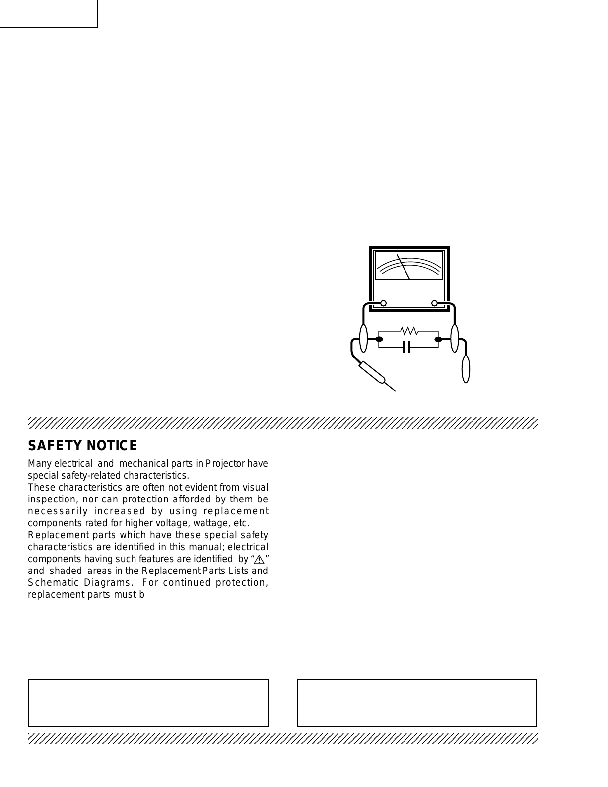
» Use an AC voltmeter with sensitivity of 5000 ohm
per volt., or higher, sensitivity to measure the AC
voltage drop across the resistor (See Diagram).
» All checks must be repeated with the AC plug
connection reversed. (If necessary, a non-polarized
adapter plug must be used only for the purpose of
completing these checks.)
Any reading of 0.3 volts RMS (this corresponds to
0.2 milliamp. A C .) or more is e xcessiv e and indicates
a potential shock hazard which must be corrected
before returning the unit to the owner.
AC
VOLTMETER
1.5k ohm (10W)
0.15µF
TEST PROBE
TO EXPOSED
METAL PARTS
CONNECT TO KNOWN
EARTH GROUND
234567890123456789012345678901212345678901234567890123456789012123456789012345678901234567890121
SAFETY NOTICE
Many electrical and mechanical parts in Projector have
special safety-related characteristics.
These characteristics are often not evident from visual
inspection, nor can protection afforded by them be
necessarily increased by using replacement
components rated for higher voltage, wattage, etc.
Replacement parts which have these special safety
characteristics are identified in this manual; electrical
components having such features are identified b y “å”
and shaded areas in the Replacement Parts Lists and
Schematic Diagrams. For continued protection,
replacement parts must be identical to those used in
the original circuit. The use of a substitute replacement
parts which do not have the same safety characteristics
as the factory recommended replacement parts shown
in this service manual, may create shock, fire or other
hazards.
AVIS POUR LA SECURITE
De nombreuses pièces, électriques et mécaniques, dans
les projecteur à présentent des caractéristiques
spéciales relatives à la sécurité, qui ne sont souvent
pas évidentes à vue.
Le degré de protection ne peut pas être nécessairement
augmentée en utilisant des pièces de remplacement
étalonnées pour haute tension, puissance, etc.
Les pièces de remplacement qui présentent ces
caractéristiques sont identifiées dans ce manuel;
les pièces électriques qui présentent ces particularités
sont identifiées par la marque “å” et hachurées dans
la liste des pièces de remplacement et les diagrammes
schématiques. Pour assurer la protection, ces pièces
doivent être identiques à celles utilisées dans le circuit
d’origine. L’utilisation de pièces qui n’ont pas les mêmes
caractéristiques que les pièces recommandées par
l’usine, indiquées dans ce manuel, peut provoquer des
électrocutions, incendies ou autres accidents.
WARNING: The bimetallic component has the primary
conductive side exposed. Be very careful in
handling this component when the power is on.
234567890123456789012345678901212345678901234567890123456789012123456789012345678901234567890121
AVERTISSEMENT:La composante bimétallique dispose du
conducteur primaire dénudé. Faire
attention lors de la manipulation de cette
composante sous tension.
4
Page 5
PG-M15X
PG-M15S
AN-M15T
NOTE TO SERVICE
PERSONNEL
UV-RADIATION PRECAUTION
The light source, metal halide lamp, in the pr ojector
emits small amounts of UV-Radiation.
AVOID DIRECT EYE AND SKIN EXPOSURE.
To ensure safety please adhere to the following:
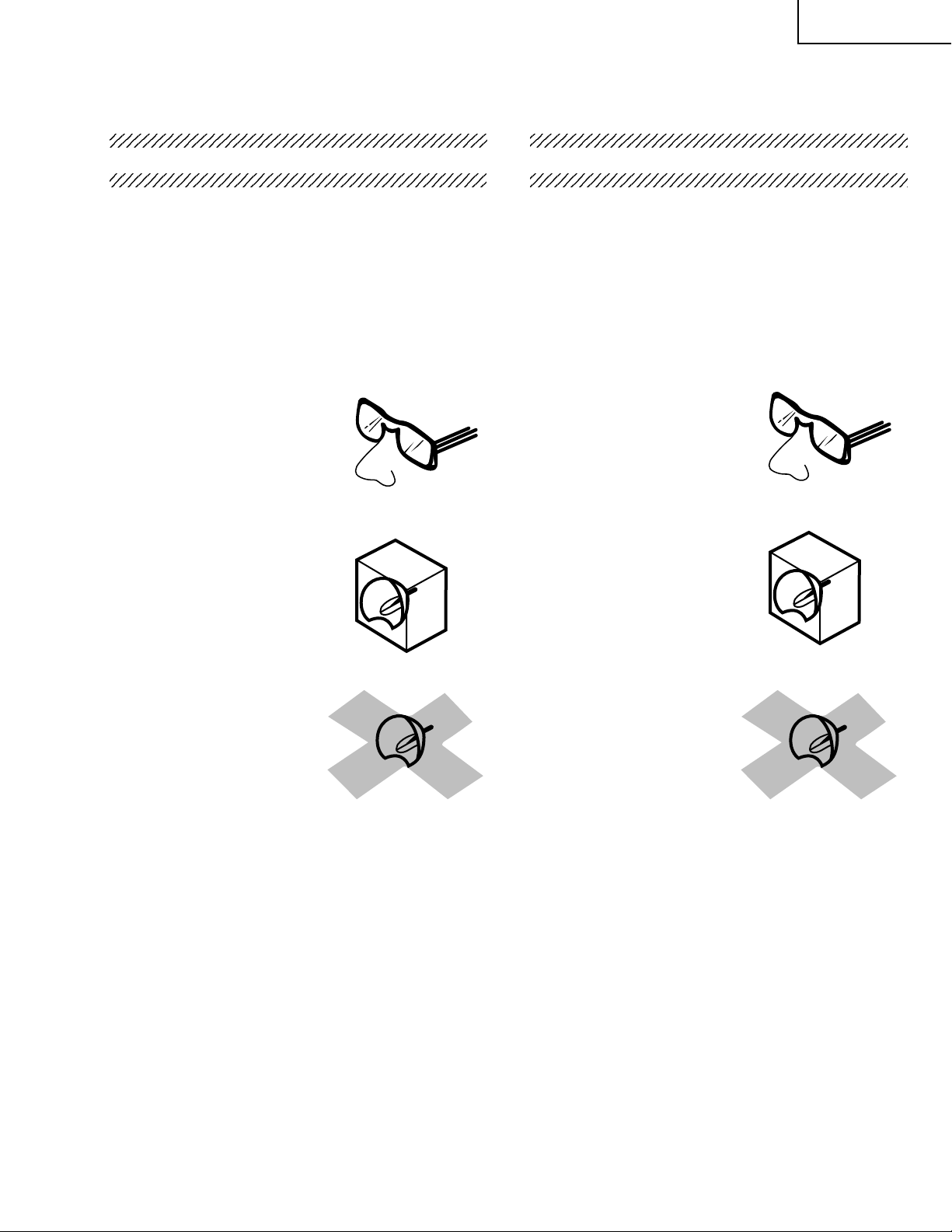
1. Be sure to wear sun-glasses when servicing the
projector with the lamp
turned “on” and the top
enclosure removed.
2. Do not operate the lamp outside of the lamp housing.
NO TE POUR LE PERSONNEL
D’ENTRETIEN
PRECAUTION POUR LES RADIATIONS UV
La source de lumière, la lampe métal halide,
dans le projecteur émet de petites quantités de
radiation UV.
EVITEZ TOUTE EXPOSITION DIRECTE
DES YEUX ET DE LA PEAU.
Pour v otre sécurité, nous vous prions de respecter
les points suivants:
1. Toujours por ter des lunettes de soleil lors d’un
entretien du projecteur
avec la lampe allumée
et le haut du coffret retiré.
2. Ne pas faire fonctionner la lampe à l’extérieur du
boîtier de lampe.
3. Do not operate for more than 2 hours with the
enclosure removed.
UV-Radiation and Medium Pressure
Lamp Precautions
1. Be sure to disconnect the AC plug when replacing
the lamp.
2. Allow one hour for the unit to cool down before
servicing.
3. Replace only with same type lamp. Type
9HJ7083119001 or BQC-PGM15X//1 rated 85V/
130W.
4. The lamp emits small amounts of UV-Radiation,
avoid direct-eye contact.
5. The medium pressure lamp involves a risk of
explosion. Be sure to follow installation instructions
described below and handle the lamp with care.
3. Ne pas faire fonctionner plus de 2 heures avec le
coffret retiré.
Précautions pour les radiations UV
et la lampe moyenne pression
1. Toujours débrancher la fiche AC lors du
remplacement de la lampe.
2. Laisser l’unité refroidir pendant une heure avant de
procéder à l’entretien.
3. Ne remplacer qu’avec une lampe du même type.
Type 9HJ7083119001 ou BQC-PGM15X//1
caractéristique 85V/130W.
4. La lampe émet de petites quantités de radiation UV éviter tout contact direct avec les yeux.
5. La lampe moyenne pression implique un risque
d’explosion. Toujours suivre les instructions
d’installation décrites ci-dessous et manipuler la
lampe avec soin.
5
Page 6
PG-M15X
4
5
PG-M15S
AN-M15T
UV-RADIATION PRECAUTION (Continued)
23456789012345678901234567890121234567890123
Lamp Replacement
Note:
Since the lamp reaches a very high temperature
during units operation replacement of the lamp
should be done at least one hour after the power
has been turned off. (to allow the lamp to cool off.)
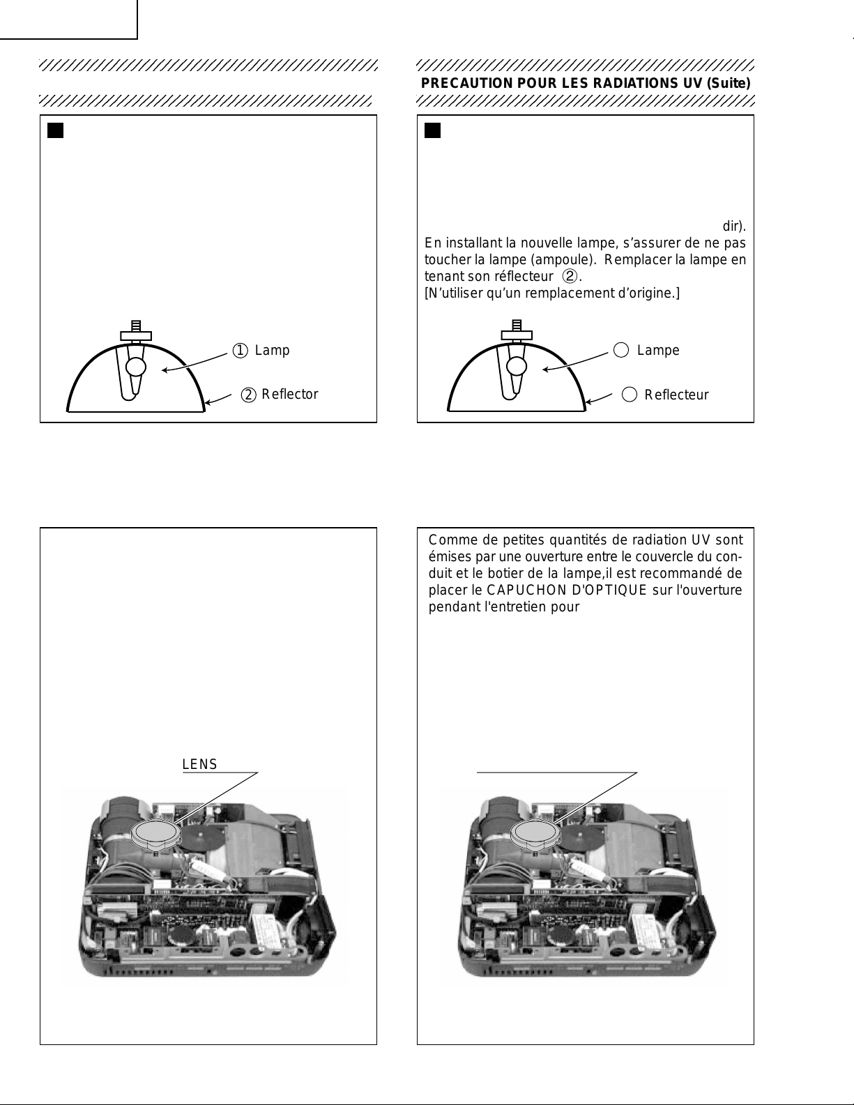
Installing the new lamp, make sure not to touch the
lamp (bulb) replace the lamp by holding its reflector
2.
[Use original replacement only.]
Lamp
1
Reflector
2
DANGER ! –– Ne ver turn the power on without the
lamp to avoid electric-shock or damage of the
devices since the stabilizer generates high v oltages
at its start.
PRECAUTION POUR LES RADIATIONS UV (Suite)
234567890123456789012345678901212345678901234
Remplacement de la lampe
Remarque:
Comme la lampe devient très chaude pendant le
fonctionnement de l’unité, son remplacement ne doit
être effectué au moins une heure après avoir coupé
l’alimentation (pour permettre à la lampe de refroidir).
En installant la nouvelle lampe, s’assurer de ne pas
toucher la lampe (ampoule). Remplacer la lampe en
tenant son réflecteur 2.
[N’utiliser qu’un remplacement d’origine.]
1
Lampe
2
Reflecteur
DANGER ! –– Ne jamais mettre sous tension sans
la lampe pour éviter un choc électrique ou des
dommages des appareils car le stabilisateur génère
de hautes tensions à sa mise en route.
Since small amounts of UV-Radiation are emitted
from an opening between the duct cover and the lamp
housing, it is recommended to place the LENS CAP
on the opening during servicing to avoid eye and
skin exposure (Fig. 1).
Note: Please obtai n a l ens cap be fore servicing a
models PG-M15X/M15S that is received without one.
LENS CAP CAPUCHON D'OPTIQUE
Comme de petites quantités de radiation UV sont
émises par une ouverture entre le couvercle du conduit et le botier de la lampe,il est recommandé de
placer le CAPUCHON D'OPTIQUE sur l'ouverture
pendant l'entretien pour éviter une exposition des
yeux et la peau (Fig. 1).
Remarque: Priére de se procurer un capuchon
d'optique acant d'entretien un modéle
PG-M15X/M15S qui est livré sans.
Figure 1.
Figure 1.
6
Page 7
PG-M15X
PG-M15S
AN-M15T
WARNING: High brightness light source, do not stare into the beam of light, or view directl y . Be especially
careful that children do not stare directly in to the beam of light.
WARNING: TO REDUCE THE RISK OF FIRE OR ELECTRIC SHOCK, DO NOT EXPOSE THIS UNIT TO
MOISTURE OR WET LOCATIONS.
CAUTION
RISK OF ELECTRIC SHOCK.
DO NOT REMOVE SCREWS
EXCEPT SPECIFIED USER
SERVICE SCREWS
CAUTION: T O REDUCE THE RISK OF ELECTRIC SHOCK,
DO NOT REMO VE CABINET.
NO USER-SERVICEABLE PARTS EXCEPT LAMP UNIT.
REFER SERVICING T O Q U ALIFIED SER VICE
PERSONNEL.
The lighting flash with arrowhead within a
triangle is intended to tell the user that
parts inside the product are risk of electric
shock to persons.
The exclamation point within a triangle is
intended to tell the user that important
operating and servicing instructions are
in the manual with the projector.
AVERTISSEMENT: Sour ce lumineuse de grande intensité. Ne pas fixer le faisceau lumineux ou le regarder
directement. Veiller particulièrement à éviter que les enfants ne fixent directement le
faisceau lumineux.
A VERTISSEMENT: AFIN D’EVITER TOUT RISQUE D’INCENDIE OU D’ELECTROCUTION, NE PAS PLACER
CET APPAREIL DANS UN ENDROIT HUMIDE OU MOUILLE.
ATTENTION
RISQUE
D’ELECTR OCUTION NE
PASRETIRER LES VIS, A
L’EXCEPTION DES VIS DE
REP ARATION UTILISATEUR
SPECIFIEES
ATTENTION: POUR EVITER TOUT RISQ UE
D’ELECTR OCUTION, NE PAS RETIRER LE CAPOT.
AUCUNE DES PIECES INTERIEURES N’EST REP ARABLE
PAR L ’UTILISA TEUR, A L’EXCEPTION DE L’UNITE DE
LAMPE. POUR T OUTE REPARATION, S’ADRESSER A UN
TECHNICIEN D’ENTRETIEN QU ALIFIE.
L’éclair terminé d’une flèche à l’intérieur
d’un triangle indique à l’utilisateur que les
pi‘eces se trouvant dans l’appareil sont
susceptibles de provoquer une décharge
électrique.
Le point d’exclamation à l’intérieur d’un
triangle indique à l’utilisateur que les
instructions de fonctionnement et
d’entretien sont détaillées dans les
documents fournis avec le projecteur.
7
Page 8
PG-M15X
PG-M15S
AN-M15T
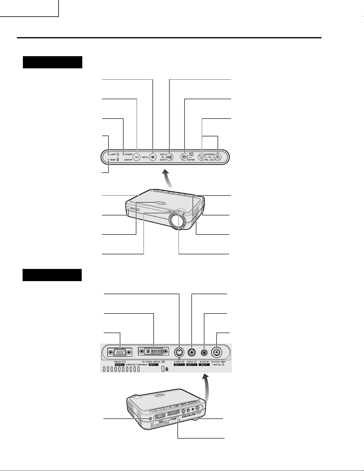
Location of Controls
Projector
Front and Top View
MENU button
ON/OFF button
POWER indicator
LAMP REPLACEMENT
indicator
TEMPERATURE WARNING
indicator
Cooling fan (Exhaust vent)
Remote control sensor
HEIGHT ADJUST button
INPUT/BACK button
AUTO SYNC/ENTER button
KEYSTONE (/)/
SELECT/ADJUST ('/") buttons
Intake vent
AC socket
Speaker
+–
FOCUS ring
Side and Rear View
S-VIDEO INPUT 2 terminal
(4-pin Mini DIN)
DVI-DIGITAL/ANALOG
INPUT 1 port (29-pin)
ANALOG OUTPUT port for
INPUT 1 (HD 15)
Remote control sensor
ZOOM knob
VIDEO INPUT 3 terminal
(RCA)
AUDIO INPUT terminal
(3.5 mm stereo Minijack)
RS-232C/MOUSE port
(7-pin Mini DIN)
Adjuster
Kensington Security Standard
connector
8
Page 9
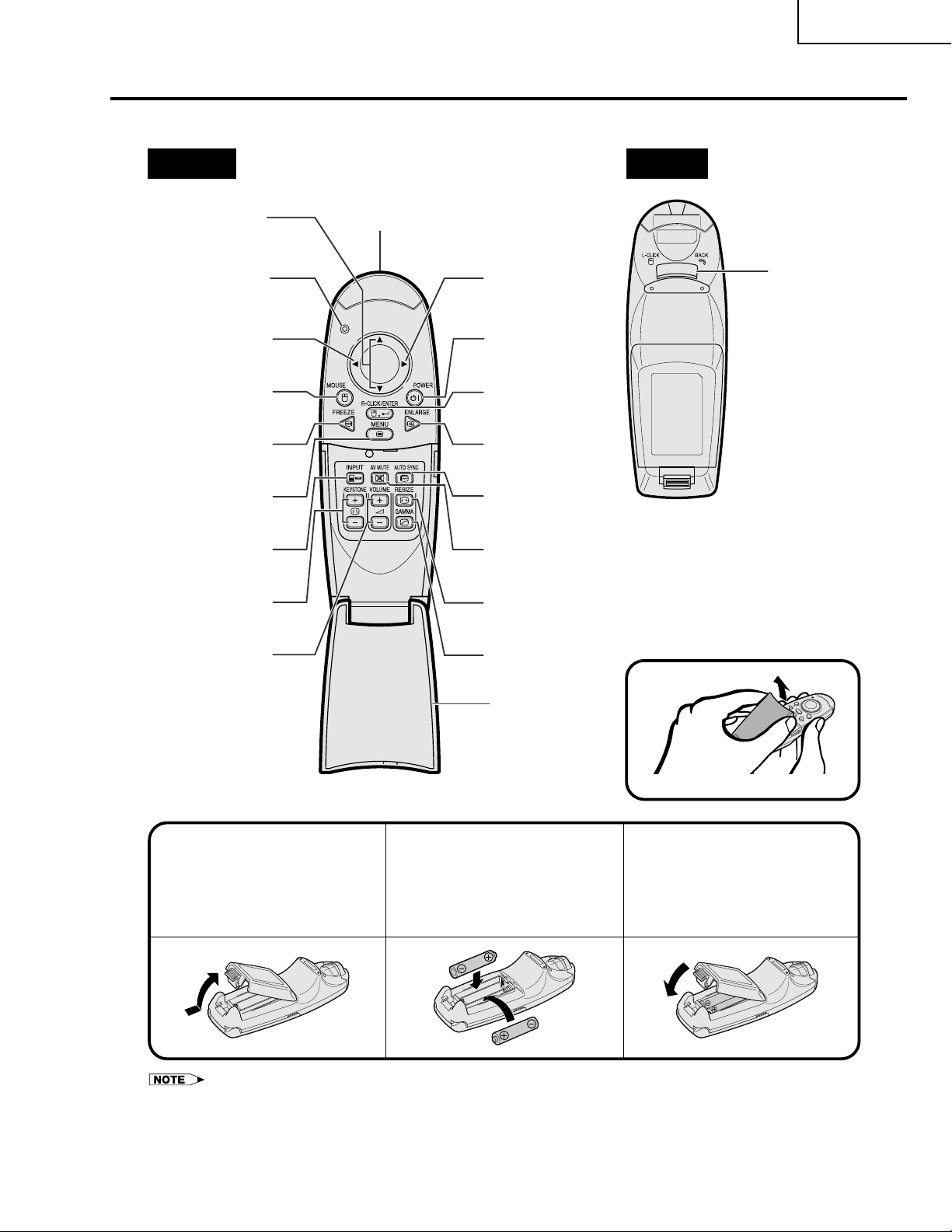
Operating the Wireless Mouse Remote Control
Remote Control
Front View Rear View
PG-M15X
PG-M15S
AN-M15T
Mouse ('/")/
Adjustment ('/")
buttons
Remote control signal
transmitter indicator
(Flashes when remote
control sends a signal)
Mouse (\ ) button
MOUSE button
FREEZE button
MENU button
INPUT button
KEYSTONE (+/– )
buttons
VOLUME buttons
Remote control signal
transmitting window
Mouse (|) button
POWER button
RIGHT-CLICK/
ENTER button
ENLARGE button
AUTO SYNC button
AV MUTE button
RESIZE button
GAMMA button
LEFT-CLICK/
BACK button
Opening the Flip Cover
Flip cover
Inserting the Batteries
Press the tab and lift open
13
the battery cover in the
direction of the arrow.
• If the remote control gets wet, wipe it dry immediately.
• Avoid excessive heat and humidity.
• If you will not be using the remote control for a long time, remove the batteries.
• Do not mix new and old or different types of batteries.
• There are operations that can only be carried out by remote control. Handle the remote control carefully.
Insert two AAA size
2
batteries, making sure
their polarities match the
and marks inside
–+
the battery compartment.
Insert the tabs on the
end of the battery cover
into their slots and press
the cover into position.
9
Page 10
PG-M15X
PG-M15S
AN-M15T
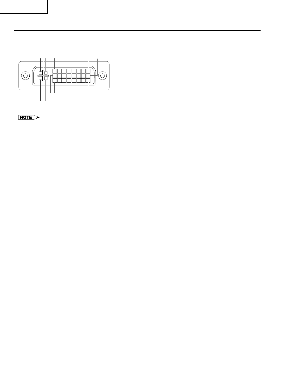
Connection Pin Assignments
DVI INPUT 1 Port: 29-pin
C5
C4 C3
24 17
9
816 1
C2 C1
•*1 Return for Ⳮ5 V, Hsync. and Vsync.
•*2 These pins are not used on this equipment.
DVI input
Pin No. Name
1 T.M.D.S. Data 2ⴑ
2 T.M.D.S. Data 2Ⳮ
3 T.M.D.S. Data 2/4 Shield
4 T.M.D.S. Data 4ⴑ*
5 T.M.D.S. Data 4Ⳮ*
6 DDC Clock
7 DDC Data
8 Vertical Sync
9 T.M.D.S. Data 1ⴑ
10 T.M.D.S. Data 1Ⳮ
11 T.M.D.S. Data 1/3 Shield
12 T.M.D.S. Data 3ⴑ*
13 T.M.D.S. Data 3Ⳮ*
14 Ⳮ5 V Power
15 Ground*
16 Hot Plug Detect
17 T.M.D.S. Data 0ⴑ
18 T.M.D.S. Data 0Ⳮ
19 T.M.D.S. Data 0/5 Shield
20 T.M.D.S. Data 5ⴑ*
21 T.M.D.S. Data 5Ⳮ*
22 T.M.D.S. Clock Shield
23 T.M.D.S. ClockⳭ
24 T.M.D.S. Clockⴑ
C1 Analog input Red
C2 Analog input Green
C3 Analog input Blue
C4 Horizontal Sync
C5 Ground
RGB input
Pin No. Name
1 Not connected
2 Not connected
2
2
2
2
1
2
2
3 Not connected
4 Not connected
5 Not connected
6 DDC Clock
7 DDC Data
8 Vertical Sync
9 Not connected
10 Not connected
11 Not connected
12 Not connected
13 Not connected
14 Ⳮ5 V Power
15 Ground
16 Not connected
17 Not connected
18 Not connected
19 Not connected
20 Not connected
21 Not connected
22 Not connected
23 Not connected
24 Not connected
C1 Analog input Red
C2 Analog input Green
C3 Analog input Blue
C4 Horizontal sync
C5 Ground
COMPONENT input
Pin No. Name
1 Not connected
2 Not connected
3 Not connected
4 Not connected
5 Not connected
6 Not connected
7 Not connected
8 Not connected
9 Not connected
10 Not connected
11 Not connected
12 Not connected
13 Not connected
14 Not connected
15 Ground
16 Not connected
17 Not connected
18 Not connected
19 Not connected
20 Not connected
21 Not connected
22 Not connected
23 Not connected
24 Not connected
C1 Analog input Pr
C2 Analog input Y
C3 Analog input Pb
C4 Not connected
C5 Ground
10
Page 11
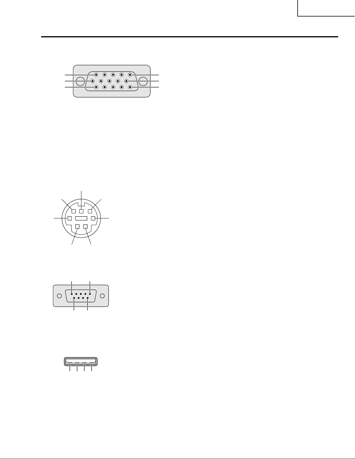
OUTPUT (INPUT 1) Signal Port: 15-pin Mini D-sub female connector
RGB output
Analog
1 Video output (red)
11
15
6
1
10
5
2 Video output
(green/sync on green)
3 Video output (blue)
4 Not connected
5 Not connected
6 Earth (red)
7 Earth (green/sync on green)
8 Earth (blue)
9 Not connected
10 GND
11 GND
12 Not connected
13 Horizontal sync signal
14 Vertical sync signal
15 Not connected
PG-M15X
PG-M15S
AN-M15T
COMPONENT output
Analog
R
(CR)
1P
2Y
B
(CB)
3P
4 Not connected
5 Not connected
6 Earth (P
7 Earth (Y)
8 Earth (P
9 Not connected
10 Not connected
11 Not connected
12 Not connected
13 Not connected
14 Not connected
15 Not connected
R
)
B
)
RS-232C T erminal: 7-pin Mini DIN female connector
6
7
5
4
21
Pin No. Signal Name
1 VCC (USB) USB Power
2 RD Receive Data
3 SD Send Data
4 USB (ⳮ) USB Data (ⳮ)
3
5 GND Signal Ground
6 USB (Ⳮ) USB Data (Ⳮ)
7 NC (Reserved)
RS-232C Port: 9-pin D-sub male connector of the DIN-D-sub RS-232C cable
15
69
Pin No. Signal Name
1CD
2 RD Receive Data
3 SD Send Data
4ER
5 SG Signal Ground
6 DR Data Set Ready
7 RS Request to Send
8 CS Clear to Send
9 CI
USB connector: 4-pin USB connector of the USB mouse control cable
Pin No. Signal Name
1 VCC USB Power
4321
2 USBⳮ USB Dataⳮ
3 USBⳭ USB DataⳭ
4 SG Signal Ground
11
Page 12
PG-M15X
PG-M15S
AN-M15T
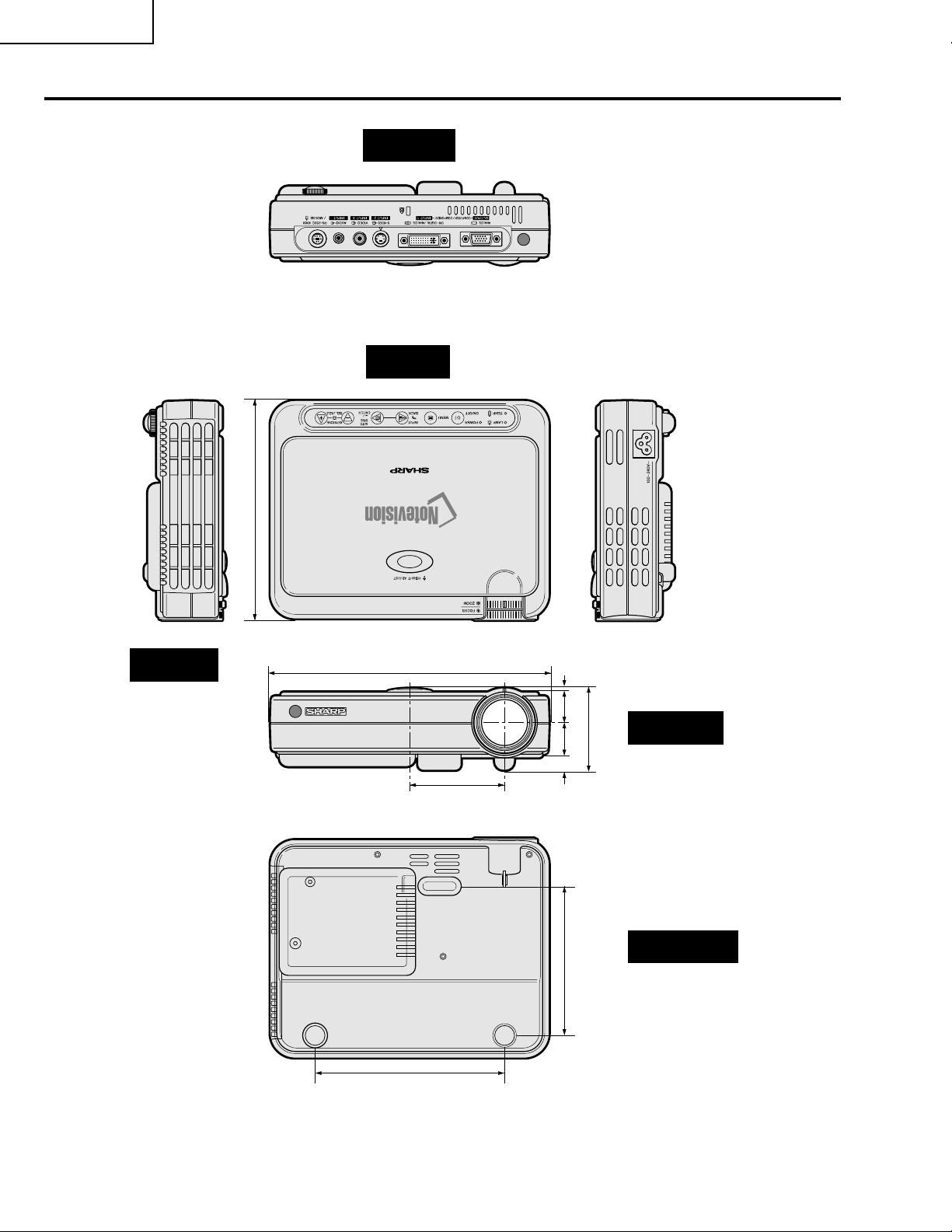
Dimensions
Rear View
T op View
Side View
(176)
64
/
59
6
855/64 (225)
1
3
/64 (76.5)
(3)
3
/
1
(13)
64
/
33
(24.5)
32
/
31
1 (25.5)
(120.5)
4
/
3
4
(66)
Front View
32
/
19
2
Bottom View
61/32 (153)
Units: inches (mm)
12
Page 13
PG-M15X
PG-M15S
AN-M15T
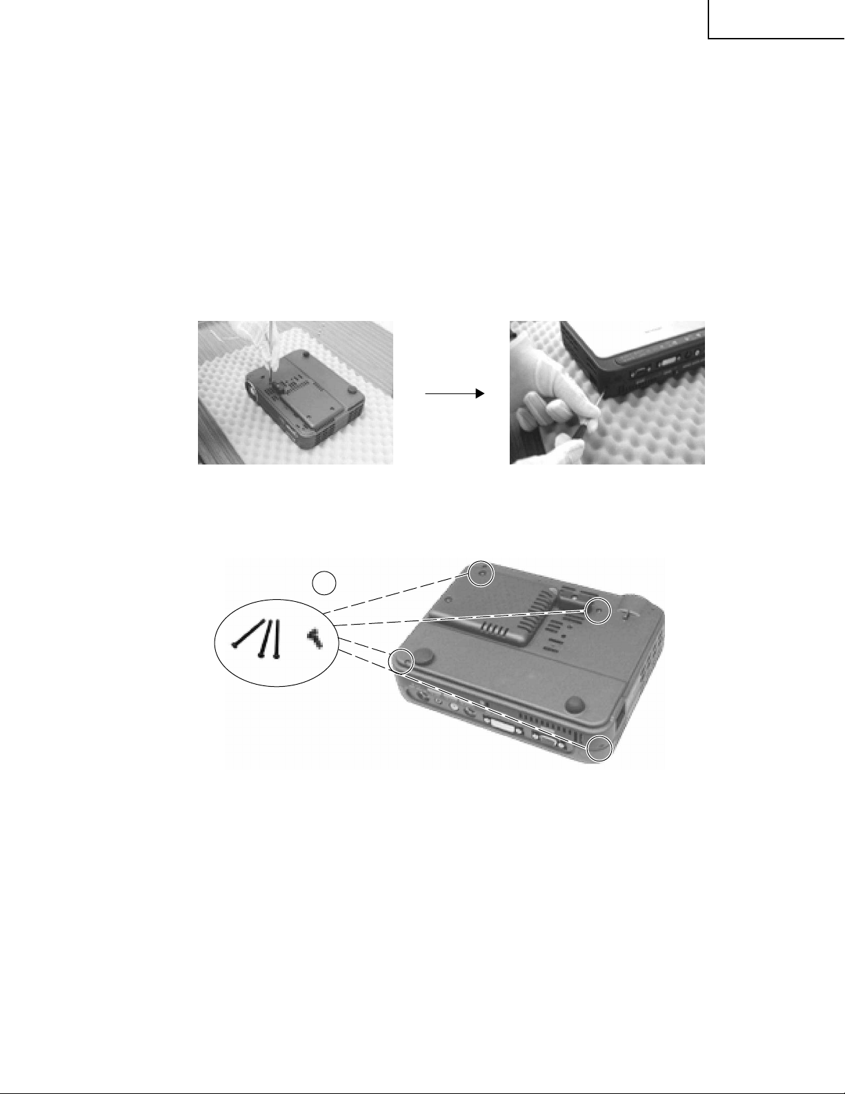
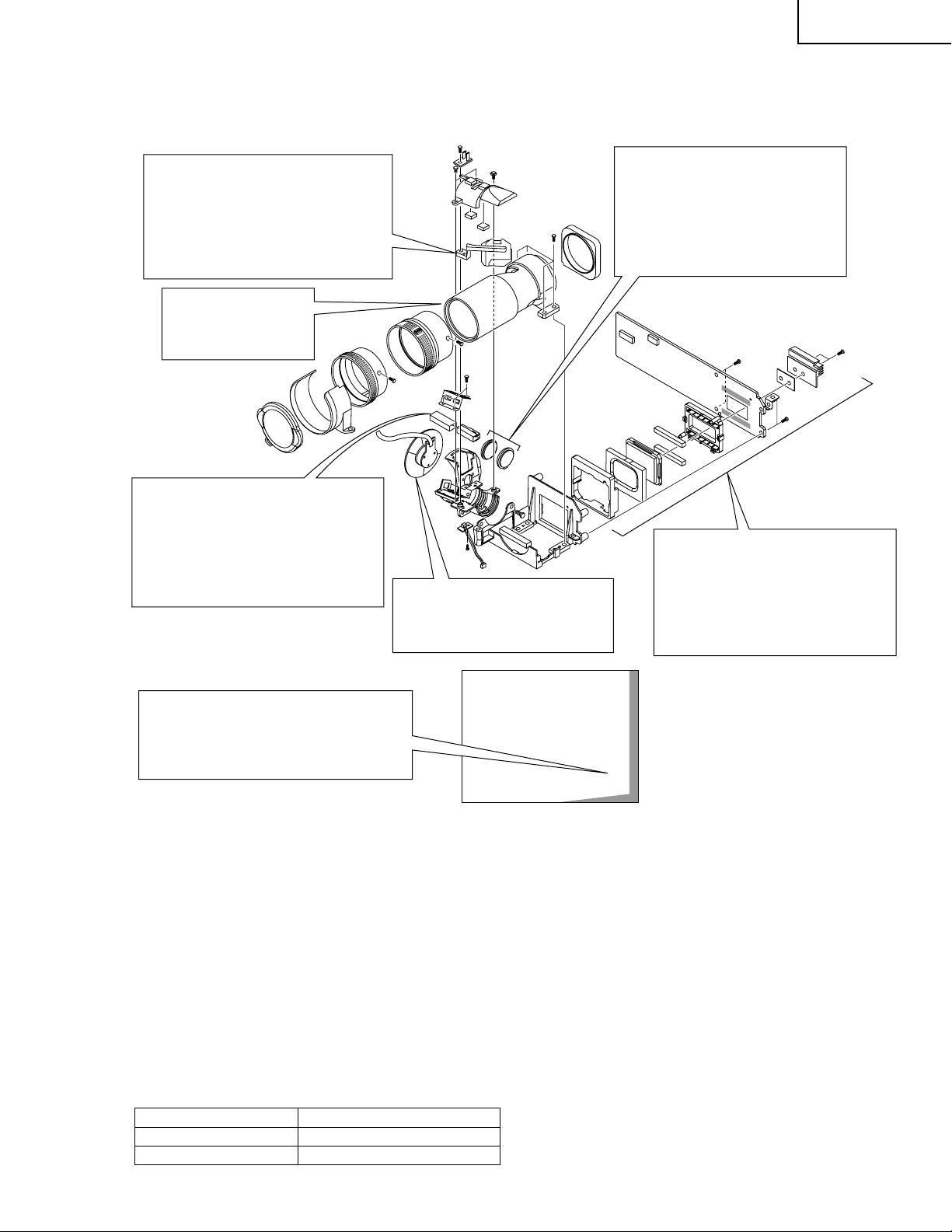
REMOVING OF MAJOR PARTS
Tools required
1. Philips screw driver (Size : 1, 2)
2. Nut driver (2.5mm)
3. Ball end hexagonal driver (5.0mm)
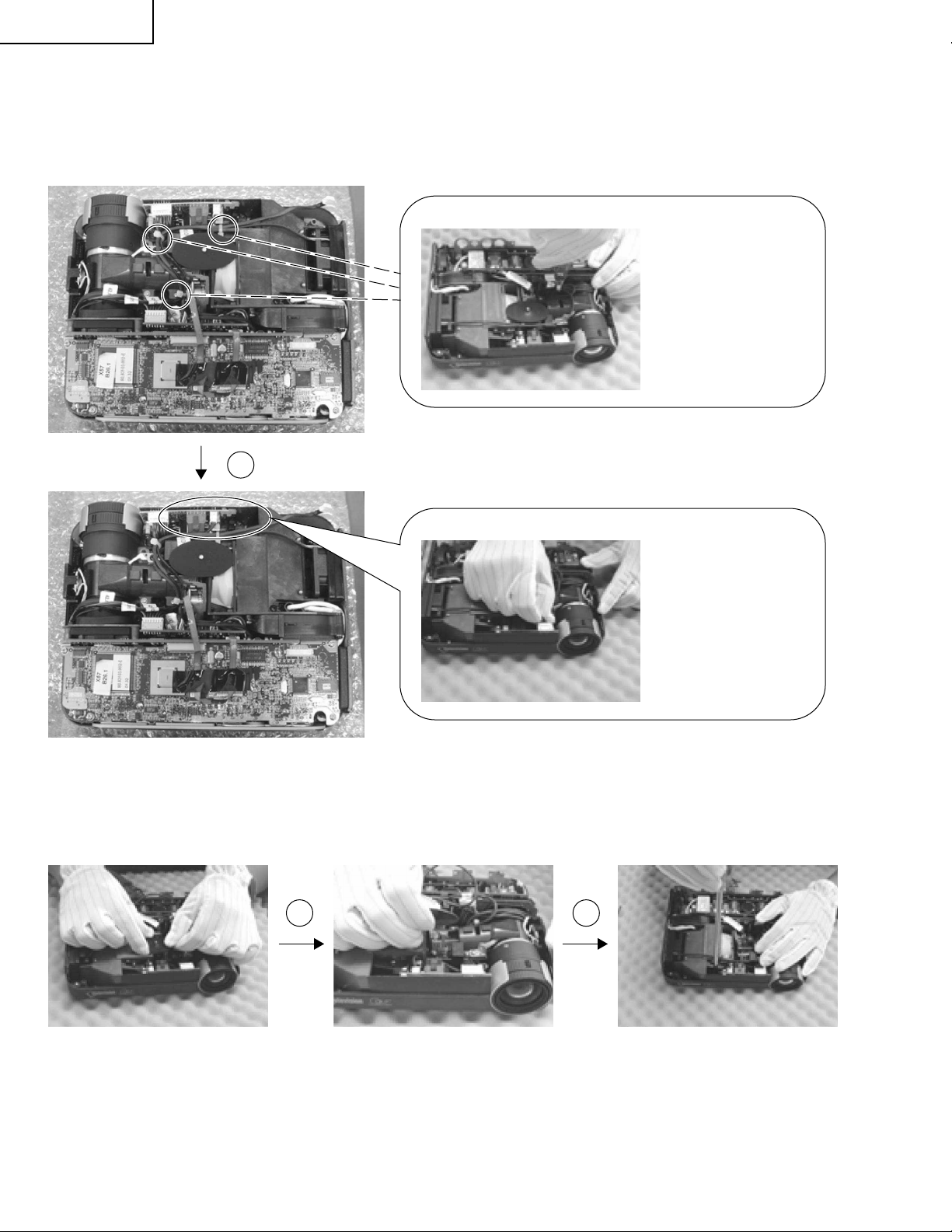
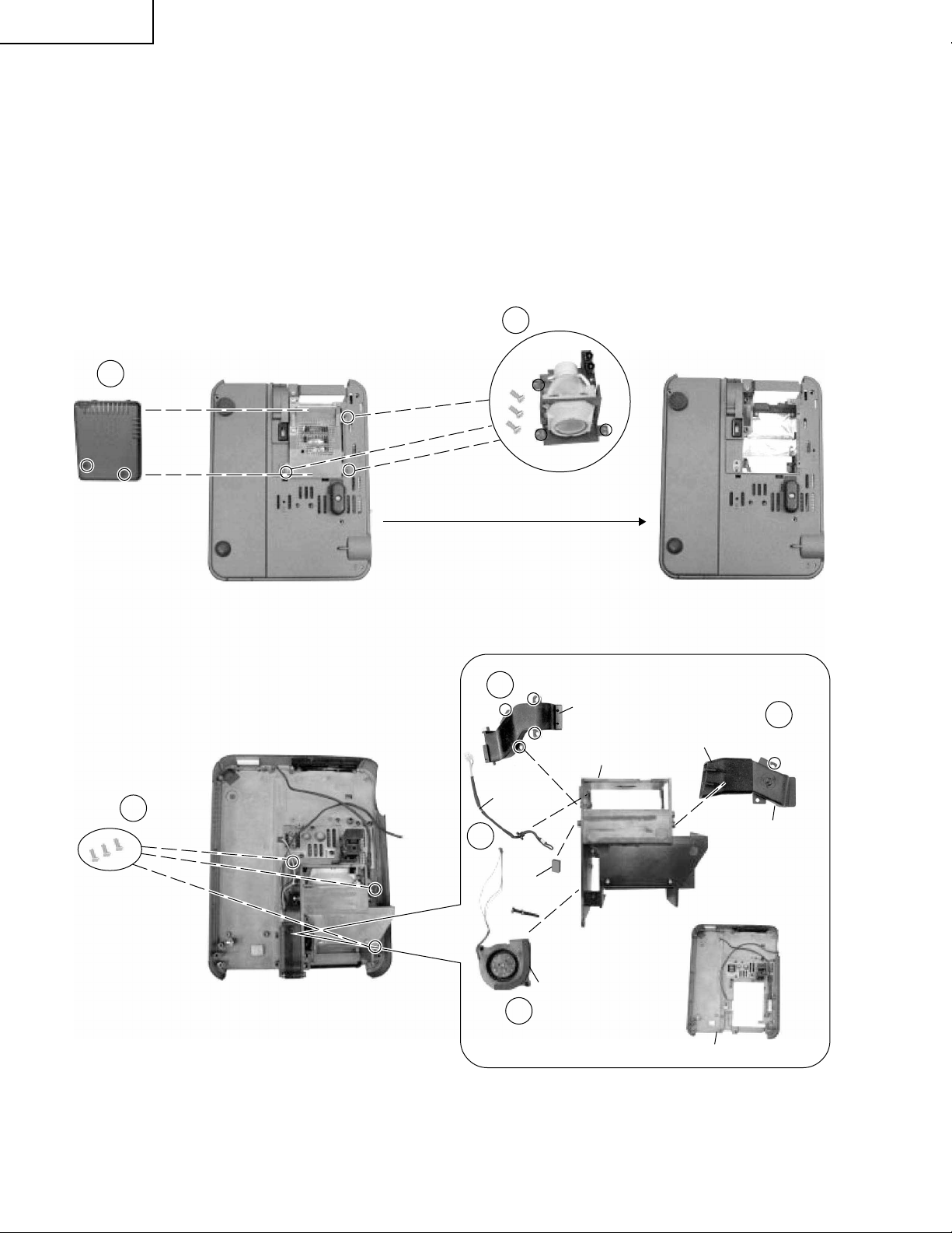
1.Disassemble Top Cover Module, Main PWB Unit and DC to DC PWB Unit
1-1. Remove four screws on Bottom Cover. (Refer to Step 1, 2.)
Step 1 Step 2
1-1
13
Page 14

PG-M15X
Terminal sheet
1-5
PG-M15S
AN-M15T
1-2. Lift up Top Cover and unplug two wires connected to IR PWB Unit and Main Unit. (Refer to Step 3~5.)
1-3. Remove Top Cover .
1-4. Remove one screw to take off IR PWB Unit and IR PWB Unit Cover.
1-5. Remove four D-SUB shafts from the D-SUB Terminals to take off Terminal Sheet. (Refer to Step 6~7.)
1-21-2
Step 3 Step 4 Step 5
1-3
IR PWB Unit Cover
Step 6
1-4
IR PWB Unit
Step 7
14
Page 15
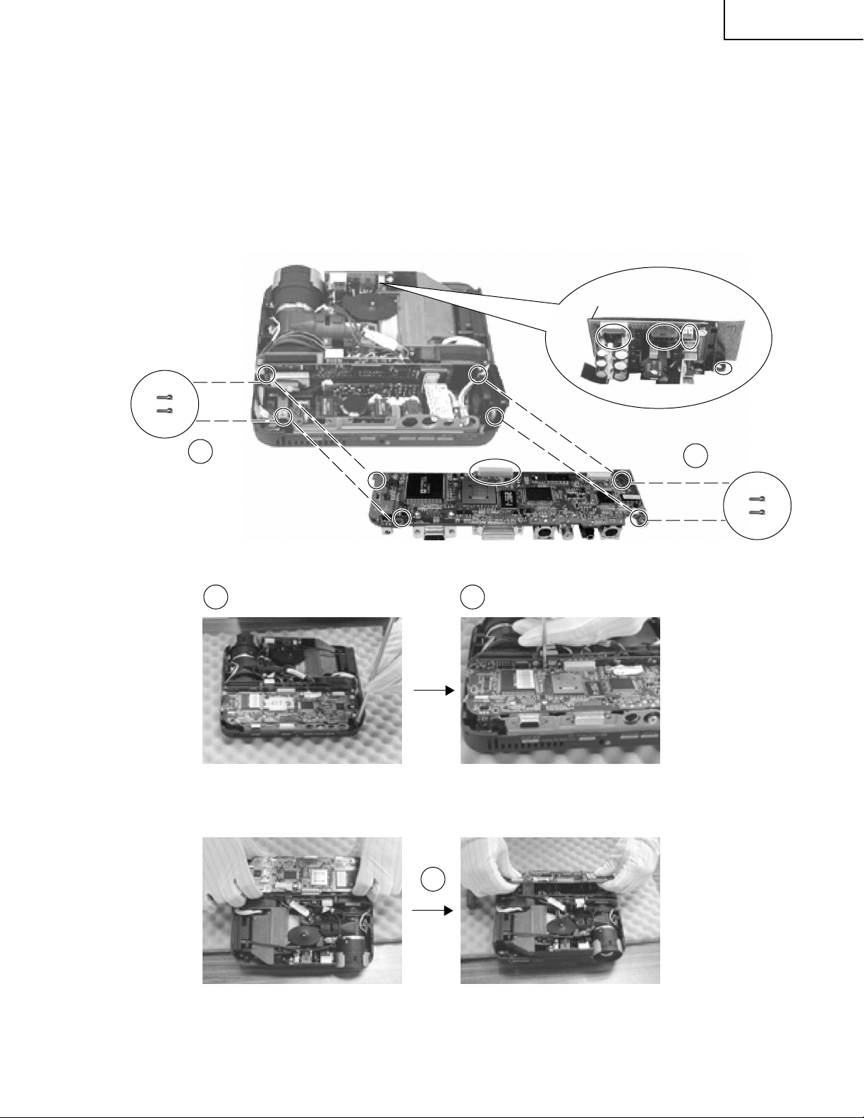
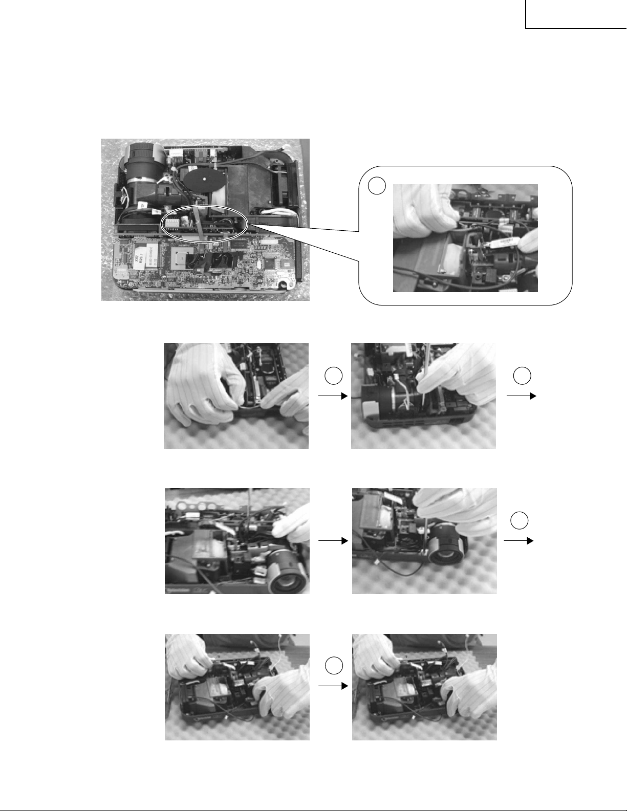
2.Disassemble Optical Engine Module
2-1. Remove 4 screws from main PWB unit.
2-2. Using a ball end hexagonal driver, loosen 2 screws holding terminal sheet holder.
(approx. 4 rotation)(Step 8.)
2-3. Place a tool in between main PWB unit and formatter PWB unit and disconnect the connector. (Step 9.)
2-4. Pull the main unit outwards and remove main PWB unit. (Step 10,11.)
DC to DC PWB Unit
PG-M15X
PG-M15S
AN-M15T
2-1
2-2 2-3
Step 8 Step 9
2-1
2-4
Step 10 Step 11
15
Page 16
PG-M15X
PG-M15S
AN-M15T
2-5. Remove one screw of DC to DC PWB Unit Holder, unplug three Connecting Cords, and then detach DC to
DC PWB Unit.
(Step 12,13.)
2-6. Remove push bar, push bar spring, and rubber. (refer to step 14~16.)
Cut three cable tie
from Optical Engine
Module.
Step 12
2-5
Step 13
Unplug three
Connecting Cords
of DC to DC PWB Unit
2-6 2-6
Step 14 Step 15 Step 16
16
Page 17
2-7. Unplug six wires of Thermal PWB Unit. (Step 17.)
2-8. Remove 5 screws from optical engine module (Step 18~20.)
2-9. Remove 2 screws from projection lens cover. (Step 21.)
2-10
. Remove optical engine module, projection lens cover, and Thermal Unit. (Step 22, 23.)
2-7
PG-M15X
PG-M15S
AN-M15T
Step 17
2-8 2-8
Step 18 Step 19
2-9
Step 20 Step 21
2-10
Step 22 Step 23
17
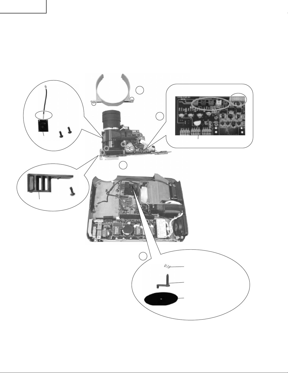
Page 18
PG-M15X
PG-M15S
AN-M15T
Projection Lens Cover
2-9
2-7
Speaker
DMD Off-Light Vent
Thermal PWB Unit
Optical Engine Module
2-8
2-6
Push Bar Spring
18
Pudh Bar
Leakage Rubber
Page 19
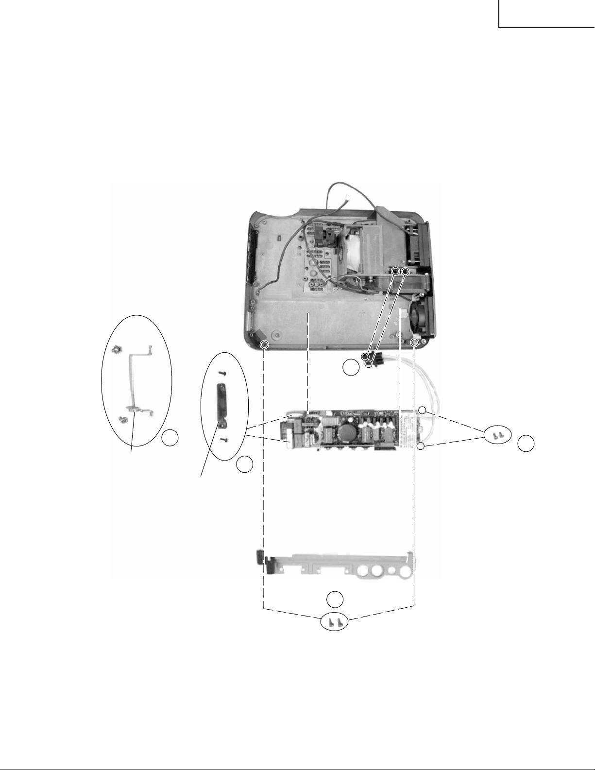
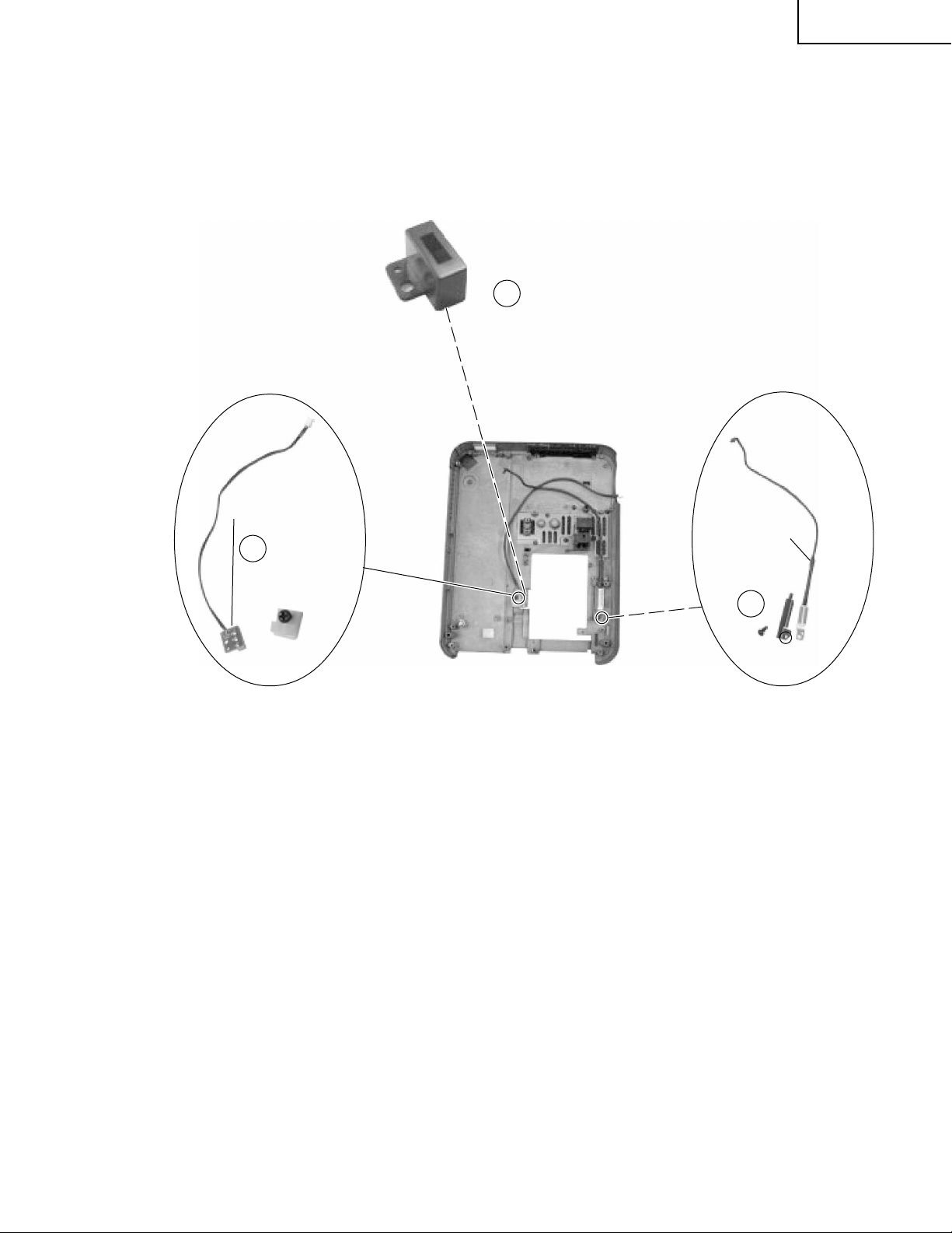
3.Disassemble Ballast PWB unit
3-1. Remove two screws and detach Terminal Sheet Holder.
3-2. Remove two screws and detach Grounding Sheet.
3-3. Remove two screws and detach AC Code Fix.
3-4. Remove two screws and detach ignitor cable from Lamp Housing.
3-5. Remove two screws and detach Ballast PWB unit.
PG-M15X
PG-M15S
AN-M15T
Grounding Sheet
3-2
3-3
AC Code Fix
3-4
3-5
Ballast PWB unit
Terminal Sheet Holder
3-1
19
Page 20
PG-M15X
PG-M15S
AN-M15T
4.Disassemble Lamp Housing
4-1. Loosen two screws and remove Lamp Cover.
4-2. Loosen three screws and lift Lamp.
4-3. Remove screw and detach Output Air Guide and Output Rubber duct.
4-4. Remove three screws and detach Lamp Housing.
4-5. Remove screw and nut then detach Fan from Lamp Housing.
4-6. Remove four screws and detach Blower Wind Guide from Lamp Housing.
4-7. Remove thermal Fuse from lamp Housing.
Lamp
4-2
4-1
Lamp Cover
4-4
4-6
4-7
Thermal
Fuse
Spacer
Blower Wind
Guide
Lamp Housing
Output
Rubber duct
4-3
Output
Air Guide
20
Fan
4-5
Bottom Cover
Page 21
4-8. Remove screw and detach SW PWB unit and Interlock Protection Cover.
4-9. Remove screw and detach Thermal Switch.
4-8
Interlock Protection Cover
PG-M15X
PG-M15S
AN-M15T
SW PWB unit
4-8
Thermal
Switch 70°
4-9
Bottom Cover
21
Page 22
PG-M15X
PG-M15S
AN-M15T
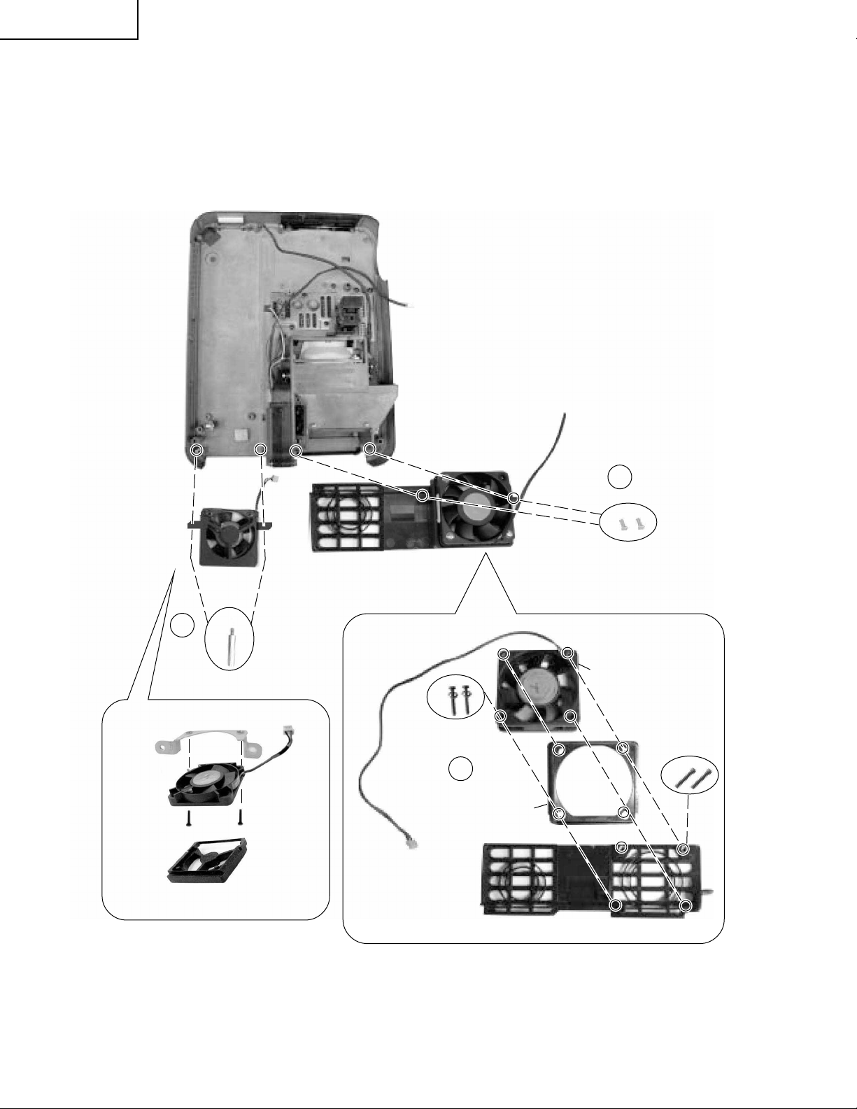
5.Disassemble Fan Module
5-1. Remove two Hexagon Copper Sticker and detach Assy Fan.
5-2. Remove two screws and detach Exhaust Window Assy.
5-3. Remove two screws and detach Fan and Rubber.
Fan Ass'y
5-1
Hexagon Copper Sticker
Fan
Rubber
5-2
Exhaust Window
Fan
5-3
Rubber
22
Page 23
RESETTING THE TOT AL LAMP TIMER
PG-M15X
PG-M15S
AN-M15T
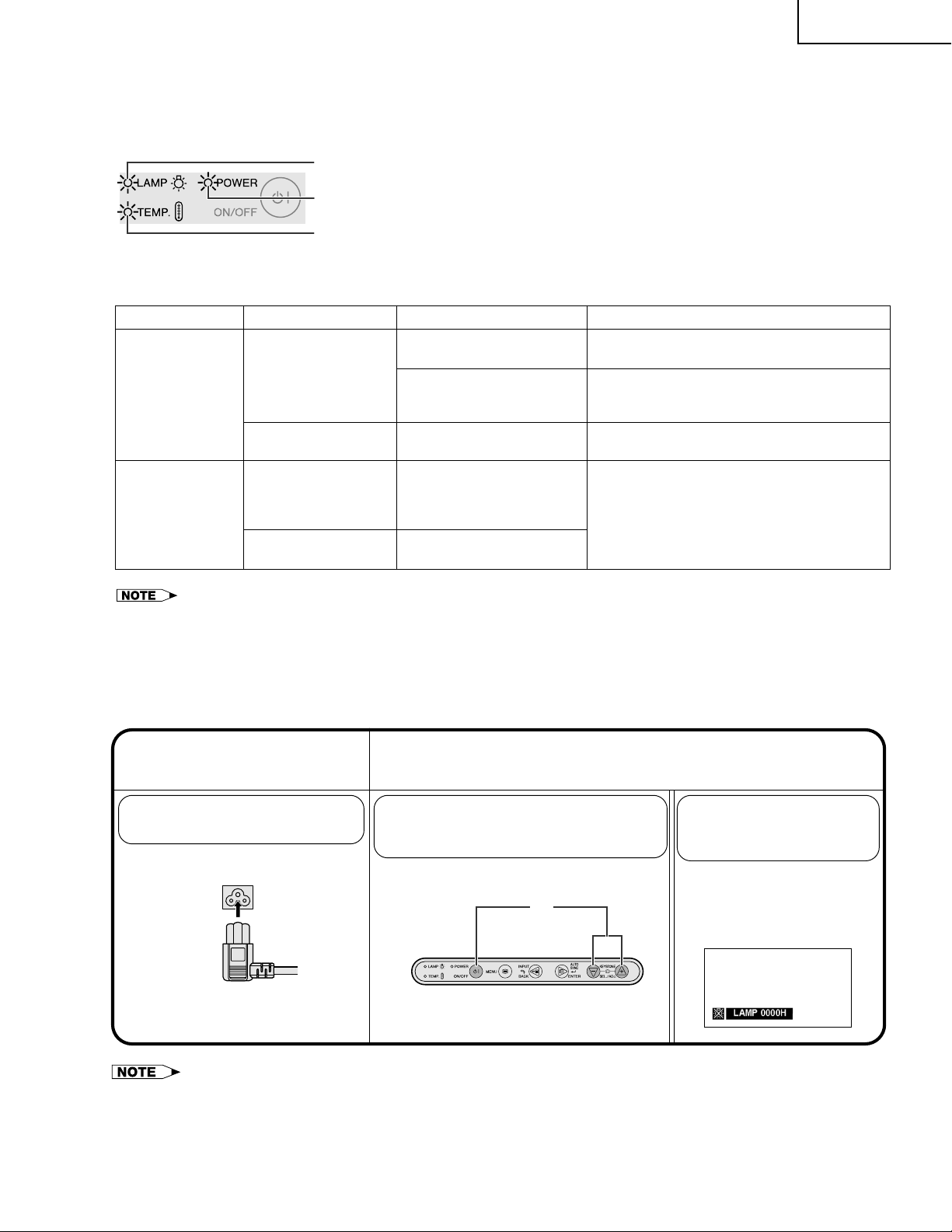
Maintenance Indicators
LAMP REPLACEMENT
indicator
POWER indicator
TEMPERATURE WARNING
indicator
Maintenance Indicator
TEMPERATURE
WARNING
indicator
LAMP
REPLACEMENT
indicator
Condition Possible Solution
The internal
temperature is
abnormally high.
The indicator flashes in
red.
The lamp does not
illuminate.
The lamp requires
replacement.
• The warning lights on the projector indicate problems
inside the projector.
• There are two warning lights: a TEMPERATURE
WARNING indicator which warns that the projector is too
hot, and a LAMP REPLACEMENT indicator which lets
you know when to change the lamp.
• If a problem occurs, either the TEMPERATURE WARNING
indicator or the LAMP REPLACEMENT indicator will
illuminate red. After turning off the power, follow the
procedures given below.
Problem
• Blocked air intake.
• Cooling fan breakdown.
• Internal circuit failure.
• Cooling down. • Wait until the indicator stops flashing and
• Burnt-out lamp.
• Lamp circuit failure.
• The lamp caga cover is
not securely installed.
• Lamp has been used for
over 1,400 hours.
• Relocate the projector to an area with proper
ventilation.
• Take the projector to your nearest Sharp
Authorized Projector Dealer or Service
Center for repair.
turns off.
• Carefully replace the lamp.
• Take the projector to your nearest Sharp
Authorized Projector Dealer or Service
Center for repair.
• If the TEMPERATURE WARNING indicator illuminates, follow the above possible solutions and then wait until the projector has cooled down
completely before turning the power back on. (At least 5 minutes.)
• If the power is turned off and then turned on again, as during a brief rest, the LAMP REPLACEMENT indicator may be triggered, preventing
the power from going on. Should this occur, take the power cord out of the wall outlet and put it back in again.
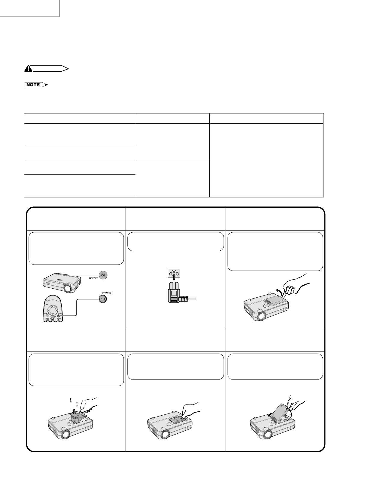
Resetting the lamp timer
Connect the power
1
cord.
Plug the power cord into the AC
socket of the projector.
Reset the lamp timer.
2
1 Press KEYSTONE (+) and
KEYSTONE (–) simultaneously and
ON/OFF at the same time.
1
“LAMP 0000H” is
displayed, indicating that
the lamp timer is reset.
Reset the lamp timer only after replacing the lamp.»
23
Page 24
PG-M15X
PG-M15S
AN-M15T
Lamp
The lamp in this projector operates for approximately 1,500 cumulative hours, depending on the usage environment. It is recommended that the lamp be replaced after 1,400 cumulative hours of use or when you notice a
significant deterioration of the picture and color quality. The lamp usage time can be checked with the On-screen
Display.
CAUTION
• Intense light hazard. Do not attempt to look into the aperture and lens while the projector is operating.
• As the usage environment can vary significantly, the projector lamp may not operate for 1,500 hours.
•“1,500 hours” above indicates average life span and should be used for reference only. This is different than the warranty period.
• For safety, the power will not be turned on from the fourth time when turning on the power without changing the lamp after use for 1,500
hours.
Condition
The LAMP REPLACEMENT indicator
illuminates red, and “LAMP” will appear in
yellow in the lower-left corner of the picture.
A significant deterioration of the picture and
color quality occurs.
The power will automatically turn off and
the projector will enter standby mode.
“LAMP” will appear in red in the lower-left
corner of the picture, and the power will
turn off.
Turn off the power.
1 3
Press ON/OFF on the projector
or POWER on the remote
control. Wait until the cooling
fan stops.
or
• Lamp has been used for
over 1,400 hours.
• Lamp has been used for
over 1,500 hours.
Disconnect the power
2
cord.
Unplug the power cord from the
AC socket.
Problem
• Purchase a replacement lamp unit (lamp
cage/module) of the current type BQCPGM15X//1 from your nearest Sharp
Authorized Projector Dealer or Service
Center.
• Replace the lamp.
If you wish, you may have the lamp
replaced at your nearest Sharp Authorized
Projector Dealer or Service Center.
Possible Solution
Remove the lamp cage
cover.
Turn over the projector and
loosen the user service screws
that secure the lamp cage cover.
Then lift open the cover in the
direction of the arrow.
Remove the lamp
46
cage.
Loosen the securing screws on
the lamp cage. Hold the lamp
cage by the handle and pull it
towards you.
Insert the new lamp cage.
5
Press the lamp cage firmly into
the lamp cage compartment.
Fasten the securing screws.
Attach the lamp cage
cover.
Slide the lamp cage cover in the
direction of the arrow. Then
tighten the user service screws.
24
Page 25

OPTICAL ADJUSTMENT AND MEASURING
1.Adjustment of Color Wheel Sensor
» Adjustment needed
1. When the color wheel unit has been replaced.
2. When the color wheel sensor has been replaced.
3. When the optical drive unit has been replaced (If a deviation from normal setting is found).
» Tools Required
1. Personal computer (run on Windows 95/98)
2. RGB cable
PG-M15X
PG-M15S
AN-M15T
25
Page 26
PG-M15X
PG-M15S
AN-M15T
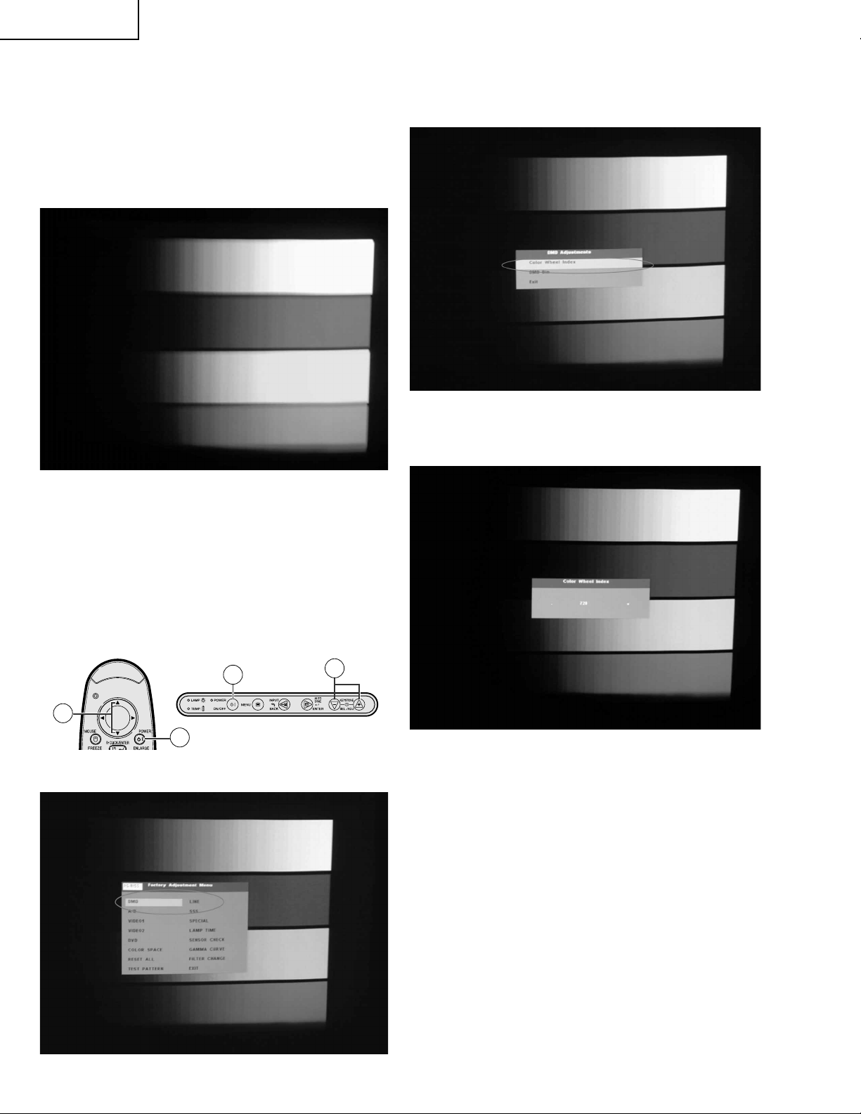
2.Color Wheel Index Adjustment
1. Choose R.G.B.W 4-color image.
1-1. Execute the “M15 Pattern dmw” command.
1-2. Click on “Color and Gray Scale”.
1-3. Left-click on the mouse to switch the pattern and to
provide the “R.G.B.W 4-color Image” (64 Intensities
for Primary Colors) output.
2. Select “DMD” on the process mode screen.
2-1. Tur n on the power. Press the ON/OFF button on the
projector or the POWER button on the remote controller .
2-2. Make sure the message “Turn Power OFF?” on the
screen. With this message still onscreen, press the
buttons in this order: “'”, “'”, “"” and “"” on the
remote controller, or “+”, “+”, “-” and “-” on the projector .
2-3. Be sure the process adjustment menu appears on
the screen, and select DMD .
3. Choose "Color Wheel Index" to do adjustment.
4. Use "+" and "-" keys on Keypad to adjust the value
to make the image have no abnormal color.
2-2
RemoteController
2-1
2-1
2-2
Projector
5. Press "Enter" key and "MENU" to go back to the
original image.
26
Page 27
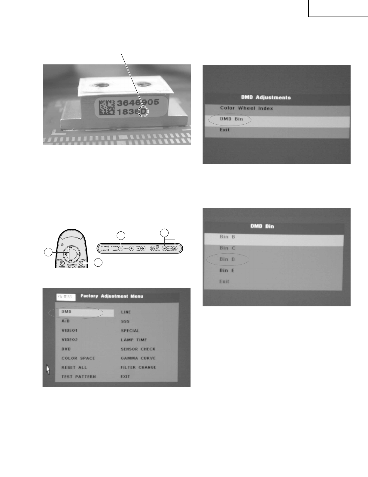
3.DMD Type Setting Sop
PG-M15X
PG-M15S
AN-M15T
1. Record type of DMD chip (An English letter in
capital) before assembly.
2. Select “DMD” on the process mode screen.
2-1. Tur n on the power. Press the ON/OFF button on the
projector or the POWER button on the remote controller .
2-2. Make sure the message “Turn Power OFF?” on the
screen. With this message still onscreen, press the
buttons in this order: “'”, “'”, “"” and “"” on the
remote controller, or “+”, “+”, “-” and “-” on the projector .
2-3. Be sure the process adjustment menu appears on
the screen, and select DMD .
3. Choose "DMD Bin" to do setting.
4. Use "+" and "-" keys on Keypad to choose DMD
type same as the type of new one
2-2
RemoteController
2-1
2-1
2-2
Projector
5. Press "Enter" key and then Press "MENU" key to go
back to the original image.
Note: Be sure to make this DMD Type Setting to keep up the
DMD chip reliability .
27
Page 28
PG-M15X
PG-M15S
AN-M15T
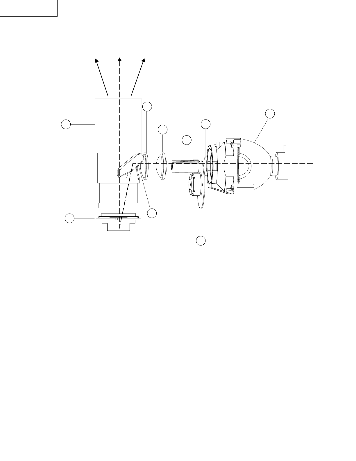
<Conceptual Drawing>
Projection Zoom Lens
8
THE OPTICAL UNIT OUTLINE
Condenser
Lens 2
6
UV-IR FilterCondenser
Lens 1
5
Rod Lens
4
2
Lamp
1
DMD Chip
9
1. OSRAM Elliptical Reflector Kind of
HID Lamp 130W
2. UV-IR Filter
3. Color Wheel
4. Rod Lens
5. Condenser Lens 1
<Basic Functions>
» UV-IR Filter : Filtering UV-IR out.
» Color Wheel : Separating the light beam into and produce R.G.B colors.
» Rod Lens : Making the light beam uniform.
» Condenser Lens 1, 2 : Condenses the illumination of Rod Lens and projects it to the effective area of
the reflection mirror.
» Reflection Mirror : This mirror reflects the light rojected to the effection area of the DMD.
» Projection Zoom Lens : Image from the DMD Chip will be projected on the screen through projection lens.
» DMD Chip : This chip turns on and off in proportion to each color component per dot depending
on the in put source.
7
Reflection Mirror
Color Wheel
3
6. Condenser Lens 2
7. Reflection Mirror
8. Projection Zoom Lens
9. DMD Chip
28
Page 29
Æ Precautions in disassembling the optical mechanism
Note:If the optical mechanism needs repairs, preferably replace the entire optical mechanism assembly
with new one. This is because to very fine adjustments are needed for some parts.
PG-M15X
PG-M15S
AN-M15T
Reflection mirror
Place back just in the same
position and direction. Otherwise
shades may appear on the
projector screen. Each positioning
is needed.
Projection lens
This lens cannot be
disassembled.
Rod lens
Place back just in the same
position and direction. Otherwise
shades may appear on the
projector screen. Each positioning
is needed.
Color wheel
Once disassembled, this part
may need readjustment.
Condenser lens 1 and 2
Place back just in the same
position and direction.
Otherwise shades may appear
on the projector screen. Each
positioning is needed.
DMD assembly
This assembly can be
disassembled. But be careful not
to allow dust and fingerprint on it.
Otherwise the images may be
adversely affected.
If the rod lens or mirror has not been
correctly adjusted, there will be
shades on the projection screen.
Æ Initial factory settings
These models require no additional electrical adjustment. If by any chance the factory settings must be made
again, however, call the process adjustment mode first in the following procedure.
1. Calling the process adjustment mode
1) Turn on the power. Press the ON/OFF button on the projector or the POWER button on the remote controller.
2) Make sure the message “Turn Power OFF?” on the screen. With this message still onscreen, press the buttons
in this order: “'”, “'”, “"” and “"” on the remote controller, or “+”, “+”, “-” and “-” on the projector.
3) Be sure the process adjustment menu appears on the screen.
2. Using the “'” and “"” buttons on the remote controller or the “+” and “-” buttons on the projector, select “SSS” and
press the “ENTER” key.
3. Using the “'” and “"” buttons on the remote controller or the “+” and “-” buttons on the projector, select the
following setting according to the destination and press the “ENTER” key.
Setting Destination
"S4" Europe, Asia, Oceania
"S6" North America
29
Page 30
PG-M15X
PG-M15S
AN-M15T
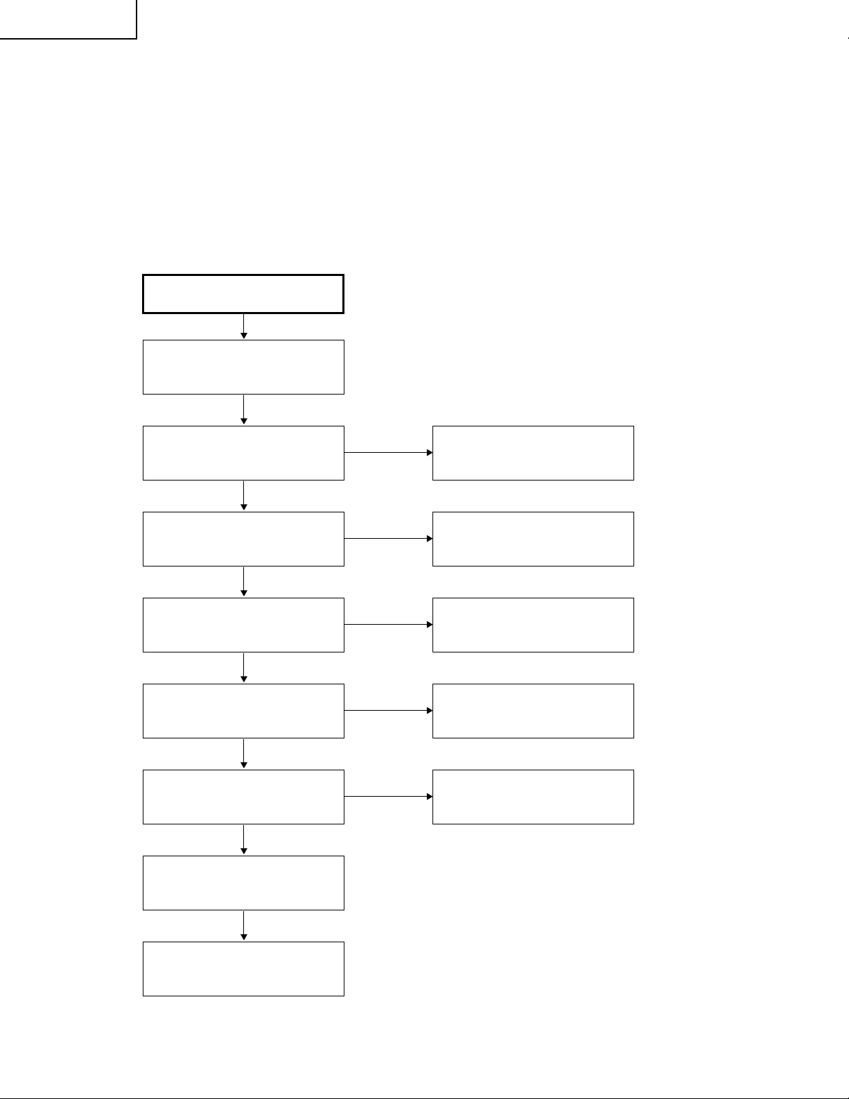
1. Equipment Needed
» PG-M15X/S
» VGA Cable, Power Cord
» PC (Personal Computer)
» Audio Input, Video Input
» Screw Driver
2. Main Procedure
Connect AC cord, VGA cable
and audio signal, then turn
power on
TROUBLE SHOOTING TABLE
Start
Is Lamp light on?
Yes
Is Image OK?
Yes
Is function OK?
Yes
Is Audio OK?
Yes
Is Remote Control OK?
Yes
No
No
No
No
No
A. Power Troubleshooting
B. Image Performance
Troubleshooting
C. Function
Troubleshooting
D. Audio Troubleshooting
Change Remote Control unit
No Fault Found
End
30
Page 31

2-1. A. Power Troubleshooting
Start
PG-M15X
PG-M15S
AN-M15T
Is LED indicator
OK?
Yes
Is Lamp OK?
Yes
Change Ballast
PWB unit
Yes
No
No
No
Check AC cord and
input power voltage
No
Supply
AC Cord
Change
Lamp unit
Main PWB unit
Troubleshooting
Yes
Lamp assembly
OK?
Yes
Change
DC to DC PWB unit
No
Main PWB unit
Troubleshooting
No
Change
Ballast PWB unit
No
Reassembly
lamp
End
31
Page 32

PG-M15X
PG-M15S
AN-M15T
2-2. B. Performance Troubleshooting
Start
Have image?
Yes
Have garbage
pattern?
No
Uniformity OK?
Yes
Is color OK?
No
Have dot defect?
No
No
Yes
(White Screen)
No
No
Yes
Main PWB unit
Troubleshooting
Main PWB unit
Troubleshooting
Change
Optical Engine
Module
Main PWB unit
Troubleshooting
Change
DMD Module
No
Change
DMD Module
No
Change
DMD Module
No No
Change
DMD Module
Change
Optical Engine
Module
Have line bar?
No
Have noise?
No
End
Yes
Yes
Adjust
frequency
Adjust
tracking
No
No
Main PWB unit
Troubleshooting
Main PWB unit
Troubleshooting
32
Page 33

2-2-1. White Screen or Garbage Pattern
Start
Check JP1 H, V SYNC in
Check U9 GH, GV SYNC
Check U17 Pin (5) DCLK
Check U16 Pin (5) MCLK
PG-M15X
PG-M15S
AN-M15T
End
2-2-2. Color abnormal (VGA)
Start
Check JP1 Pins (25), (26) and
(27)(RGB input)
Check U9 A/D coverter or
U7 (for DVI)
Check U11
Check JP2 is short circuit or not
Change DMD PWB unit
End
* When you fix it, suggest use white frame or RGBW color display.
33
Page 34

PG-M15X
PG-M15S
AN-M15T
2-3. C. Function Troubleshooting
Start
Does OSD
No
show up?
Yes
Can function
No
be adjusted?
Yes
End
2-4. D. Audio Troubleshooting
Start
Can hear
No
sound?
Is SW PWB unit
OK?
No
Change
SW PWB unit
Main PWB unit
Troubleshooting
Main PWB unit
Troubleshooting
Yes
No
Is Remote
Controller OK?
No
Change
battery
No
Change
Remote Controller
Change
Spearker
Yes
Main PWB unit
Troubleshooting
Yes
Sound is clear
without noise?
Yes
End
No
Main PWB unit
Troubleshooting
34
Page 35

3. Main PWB unit Troubleshooting
»»
» Condition-1.
»»
PC Source
Check VGAIN-R/G/B,
HSYNCIN, VSYNCIN PATH
PG-M15X
PG-M15S
AN-M15T
Check U9 AD9886
Yes
Check U11 PW164
Yes
DMD PWB unit
»»
» Condition-2.
»»
VIDEO Source
S-VIDEO Source
Check CY_out, C_out/Y_out,
PATH
No
Change AD9886
No
Change PW164
Check U40 ADG663
Yes
Check U24 VPC3230
Yes
Check U11 PW164
Yes
DMD PWB unit
No
Change ADG663
No
Change VPC3230
No
Change PW164
35
Page 36

PG-M15X
PG-M15S
AN-M15T
»»
» Condition-3.
»»
Component-i Source
Check Cr/Pr, YIN, Cb/Pb
PATH
Check U2 LT1399
Check U24 VPC3230
Check U11 PW164
DMD PWB unit
»»
» Condition-4.
»»
DVI Source
No
Change LT1399
Yes
No
Change VPC3230
Yes
No
Change PW164
Yes
Check
RX0+/RX0-,
RX1+/RX1-,
RX2+/RX2-,
RXC+/RXC-,
PATH
Check U7 Sil151A
Yes
Check U11 PW164
Yes
DMD PWB unit
No
Change Sil151A
No
Change PW164
36
Page 37

»»
» Condition-5.
»»
PC Source Output
PG-M15X
PG-M15S
AN-M15T
Check U3 LT1399
MONITOR DISPLAY
»»
» Condition-6.
»»
AUDIO Source
Check U22 LM4832
Check U23 LM4871
No
Change LT1399
Yes
No
Change LM4832
Yes
No
Change LM4871
Yes
SPEAKER OUTPUT
»»
» Condition-7.
»»
RREMOTE MOUSE
Check IR RECEIVER
Front : JP3
Back : IR1
Yes
Check U25 CY7C63612
Yes
REMOTE MOUSE CONTROL
No
Change IR RECEIVER
No
Change CY7C63612
37
Page 38

PG-M15X
PG-M15S
AN-M15T
Technische Daten
Produkttyp
Modell
Videosystem
Wiedergabeverfahren
DMD-Panel
Objektiv
Projektionslampe
Kontrastverhältnis
Videoeingangssignal
S-Videoeingangssignal
Komponenten-Eingangssignal
Horizontale Auflösung
RGB-Computereingangssignal
Punktetakt
Vertikale Frequenz
Horizontale Frequenz
Audioeingangssignal
Audioausgang
Lautsprechersystem
Nennspannung
Eingangsspannung
Nennfrequenz
Nennaufnahme
Energieverbrauch
Betriebstemperatur
Lagertemperatur
Gehäuse
I/R-Trägerfrequenz
Abmessungen (ca.)
Gewicht (ca.)
Mitgeliefertes Zubehör
Ersatzteile
Digitaler Multimedia-Projektor
PG-M15X/PG-M15S
NTSC/NTSC 4.43/PAL/PAL-M/PAL-N/PAL 60/SECAM/DTV480i
Single Chip Digital Micromirror Device™ (DMD™) von Texas Instruments
Panelgröße: 0,7 (17,8 mm), 1 Chip XGA DMD/SVGA DMD
Anzahl der Bildpunkte: 786.432 Bildpunkte (1.024 [H] 768 [V])/PG-M15X
480.000 Bildpunkte (800 [H] 600 [V])/PG-M15S
1-1,2 Zoomobjektiv, F2,2–2,4, f = 28,5–34,2 mm
Hochintensive Entladungslampe (HID-Lampe), 130 W Wechselstromspannung
500:1
RCA-Stecker (INPUT 3): VIDEO, Gemischtes Video, 1,0 Vs-s, negatives Sync.-Signal, 75 Ω
terminiert
4-Pin Mini DIN-Stecker (INPUT 2)
Y (Luminanz-Signal): 1,0 Vs-s, negatives Sync.-Signal, 75 Ω terminiert
C (Chrominanz-Signal): Stoß 0,286 Vs-s, 75 Ω terminiert
29-Pin-Stecker (INPUT 1)
Y: 1,0 Vs-s, negatives Sync.-Signal, 75 Ω terminiert
B
: 0,7 Vs-s, 75 Ω terminiert
P
R
: 0.7 Vs-s, 75 Ω terminiert
P
580 Fernsehzeilen (Videoeingang)
29-Pin-Stecker (INPUT 1)
RGB getrennt/Sync. auf Grün-Typ analoger Eingang: 0–0,7 Vs-s, positiv, 75 Ω terminiert
ORIZONTALES SYNC
H
ERTIKALES SYNC
V
.-S
.-S
IGNAL
: TTL-Pegelsignal (positiv/negativ)
IGNAL
: Wie oben
25–135 MHz
56–85 Hz
31,5–80 kHz
INIJACK
3,5 ø M
: AUDIO, 0,4 Vrms mehr als 47 kΩ (Stereo)
2,0 W (monaural)
4 2,8 cm
100–240 V Wechselstromspannung
2,0 A
50/60 Hz
180 W
<680 BTU/Stunde
41° bis 95°F (5° bis 35°C)
14° bis 140°F (10° bis 60°C)
Magnesium-Legierung (Anschlußplatte, Lampenabdeckung und seitliche Belüftungsplatte
sind aus Kunststoff)
38 kHz
55
⁄64 1 31⁄32 6 59⁄64 (225 (B) 50 (H) 176 (T) mm) (nur Hauptgerät)
8
55
⁄64 2 19⁄32 6 31⁄32 (225 (B) 66 (H) 177 (T) mm) (einschließlich Drehfüße und
8
vorstehende Teile)
3,5 pfd. (1,6 kg)
Fernbedienung, Zwei Batterien der Größe AAA, Netzkabel für USA, Kanada usw. (5 11,
1,8 m), Netzkabel für Europa, ausgenommen Großbritannien (5 11, 1,8 m), Netzkabel für
Großbritannien, Hongkong und Singapur (5 11, 1,8 m), Netzkabel für Australien,
Neuseeland und Ozeanien (5 11, 1,8 m), DVI-Analog auf VGA-kabel, DVI-Analog auf
VGA-Adapter, PC-Audiokabel (6 7, 2,0 m), DIN-D-Sub RS-232C-Kabel, (6
1
/2, 16,5 cm)
RGB-Computerkabel (5 11, 1,8 m), USB-Maus-Steuerungskabel (5 11, 1,8 m),
Videokabel (5 11, 1,8 m), S-Videokabel (5 11, 1,8 m), AV-Audiokabel (5 11, 1,8 m),
Weiche Tragetasche, Objektivkappe mit Band, CD-ROM, Bedienungsanleitung des
Projektors, Kurzreferenz des Projektors
Fernbedienung (9HJ7583104001), Zwei Batterien der Größe AAA (9HJ4683101001),
Netzkabel für USA, Kanada usw. (9HJ4283114001), Netzkabel für Europa, ausgenommen
Großbritannien (9HJ4283116001), Netzkabel für Großbritannien, Hongkong und Singapur
(9HJ4283117001), Netzkabel für Australien, Neuseeland und Ozeanien (9HJ4283118001),
DVI-Analog auf VGA-Kabel (9HJ4283108001), DVI-Analog auf VGA-Adapter
(9HJ4283124001), PC-Audiokabel (9HJ4283120001), DIN-D-Sub RS-232C-Kabel
(9HJ4283123001), RGB-Computerkabel (9HJ4283111001), USB-Maus-Steuerungskabel
(9HJ4283122001), Videokabel (9HJ4283112001), S-Videokabel (9HJ4283113001), AVAudiokabel (9HJ4283121001), Weiche Tragetasche (9HJ5383101001), Objektivkappe mit
Band (9HJ7083117001), CD-ROM (9HJ3683104001), Bedienungsanleitung des Projektors
(9HJ3683107001), Kurzreferenz des Projektors (9HJ3683110001)
Dieser Projektor von SHARP verwendet ein DMD-Panel. Dieses
hochentwickelte Panel enthält 786.432 (PG-M15X)/480.000 (PGM15S) Pixel. Bei allen technologisch fortschrittlichen, elektronischen
Geräten, z. B. Großbild-Fernsehern, Videosystemen bzw.
Videokameras, sind bestimmte Toleranzgrenzen für die Funktionen
gegeben.
Änderungen der technischen Daten ohne vorherige Ankündigung vorbehalten.
Dieses Gerät hat einige inaktive, innerhalb akzeptierter
Toleranzgrenzen liegende Bildpunkte, die als inaktive Punkte auf der
Bildwand wiedergegeben werden. Dies hat keinen Einfluß auf die
Bildqualität und die Lebensdauer des Gerätes.
38
Page 39

HINWEIS FÜR DAS WARTUNGSPERSONAL
5
Objectivedeckel
PG-M15X
PG-M15S
AN-M15T
ACHTUNG: UV-STRAHLUNG
234567890123456789012345678901212345678901234
Die Lichtquelle im Projektor, eine Metall-HalogenLampe, gibt eine geringe UV-Strahlung ab.
DIREKTE BESTRAHLUNG AUF AUGEN
UND HAUT MUSS VERMIEDEN WERDEN.
Zur Gewährleistung der Sicherheit muß folgendes
beachtet werden:
1. Bei Arbeiten am Projektor bei eingeschalteter
Lampe und abgenommenem oberen Gehäuse
muß unbedingt eine Sonnenbrille getragen
werden.
2. Die Lampe darf nicht außerhalb des
Lampengehäuses eingeschaltet werden.
Ë Aus wechseln der Lampe
Hinweis:
Da die Lampe während des Betriebs sehr heiß wird,
sollte die Lampe erst ausgewechselt werden, nachdem
das Gerät mindestens eine Stunde ausgeschaltet war ,
damit die Lampe ausreichend abkühlen kann.
Beim Installieren der neuen Lampe muß darauf
geachtet werden, die Lampe selbst (Glaskolben)
nicht zu berühren. Vielmehr muß die Lampe am
Reflektor 2 gehalten werden.
[Es darf nur ein Original-Ersatzteil verwendet
werden.]
Lampe
1
2
Reflektor
GEFAHR! — Niemals die Spannungsversorgung
einschalten, ohne daß eine Lampe vorhanden ist,
um elektrische Schläge und Schäden am Gerät zu
vermeiden, da der Stabilisator anfangs hohe
Spannungen erzeugt.
3. Betrieb für länger als 2 Stunden bei
abgenommenem Gehäuse ist nicht zulässig.
Zur Beachtung bei UV-Strahlung
und Mitteldruck-Lampen
1. Vor dem Auswechseln der Lampe muß der
Netzstecker gezogen werden.
2. Vor Durchführung von Wartungsarbeiten muß das
Gerät eine Stunde abkühlen.
3. Nur mit dem gleichen Lampentyp ersetzen Typ
9HJ708311901 oder BQC-XGM15X//1;
Nennleistung 85 V/130 W.
4. Die Lampe gibt eine geringe UV-Strahlung ab,
daher muß direkter Augenkontakt vermieden
werden.
5. Die Mitteldruck-Lampe weist ein Explosionsrisiko
auf. Daher müssen die nachstehenden
Installationsanweisungen beachtet werden, und die
Lampe muß vorsichtig behandelt werden.
Da eine geringe UV-Strahlung aus einer Öffnung
zwischen der Schachtabdeckung und dem
Lampengehäuse austritt, sollte der Objektivdeckel
bei Wartungsarbeiten auf die Öffnung gesetzt
werden, um die Bestrahlung von Augen und Haut
zu vermeiden (Abb. 1).
Hinweis: Besorgen Sie sich einen Objektivdeckel,
bevor Sie Arbeiten an einem Modelle XGPG-M15X/S durchführen, das keinen
Objektivdeckel aufweist.
Abbildung 1.
39
Page 40

PG-M15X
PG-M15S
AN-M15T
Bedienelemente
Projektor
Ansicht von vorne und oben
Menü-Taste (MENU)
Betriebs-Taste (ON/OFF)
Betriebsanzeige
Lampenaustausch-Anzeige
Temperaturwarnanzeige
Kühlventilator (Luftauslaß)
Fernbedienungs-Sensor
Höheneinstellungs-Taste
(HEIGHT ADJUST)
Eingang-/Zurück-Taste
(INPUT/BACK)
Automatische
Synchronisierung-/EingabeTaste (AUTO SYNC/ENTER)
Trapezentzerrung-( )/Wahl-/
Einstellungs-Tasten ( )
(KEYSTONE/SEL./ADJ.)
Lufteinlaß
Steckanschluß
Lautsprecher
/+–
'/"
Fokussierring
Seiten- und Rückansicht
S-Videoeingangsanschluß 2
(4-Pin Mini DIN)
DVI-DIGITAL/ANALOG
Eingangs-Port 1 (29-Pin)
Analoger Ausgangs-Port für
Eingang 1 (HD 15)
(ANALOG OUTPUT)
Fernbedienungs-Sensor
Zoom-Knopf
Videoeinganganschluß 3
(RCA) (VIDEO INPUT 3)
Audioeingangsanschluß
(AUDIO INPUT)
(3,5 mm Stereo-Minibuchse)
RS-232C/Maus-Port
(7-Pin Mini DIN)
(RS-232C/MOUSE)
Einstellfuß
40
Standardanschluß für
Kensington-Sicherheitssperre
Page 41

Betrieb mit der drahtlosen Maus-Fernbedienung
Vorderansicht Ansicht von hinten
Fernbedienung
Maus-( )/
Einstellungs-( )
Tasten
Standbild-Taste
(FREEZE)
Maustaste ( )
MAUS-Taste
(MOUSE)
Eingangs-Taste
(INPUT)
Menü-Taste
(MENU)
T r apezverzeichnungs-
Tasten
(KEYSTONE)( )
Lautstärke-Tasten
(VOLUME)
Netz-Taste
(POWER)
Rechte Klick-/
Eingabe-Taste
(R-CLICK/ENTER)
Vergrößern-Taste
(ENLARGE)
Auto-Synchron-Taste
(AUTO SYNC)
Größe-Taste (RESIZE)
Linke Klick-/
Zurück-taste
(L-CLICK/
BACK)
AV-StummschaltungsTaste (AV MUTE)
GAMMA-Taste
Abdeckung
Maustaste ( )
Einsetzen der Batterien
1
Auf den Vorsprung
drücken und die
Batteriefachabdeckung in
Pfeilrichtung öffnen.
23
Zwei Batterien der Größe
AAA einlegen und
sicherstellen, daß die
Pole mit der und
Markierung im
Batteriefach
übereinstimmen.
Die V orsprünge auf dem
Ende der
Batteriefachabdeckung
in die Schlitze schieben
und die Abdeckung auf
das Batteriefach
drücken.
Öffnen der Abdeckung
Fenster für die Übertragung des
Fernbedienungs-Signals
• Wenn die Fernbedienung naß wird, sollte sie sofort trocken gewischt werden.
• Die Fernbedienung sollte nicht übermäßiger Wärme oder Feuchtigkeit ausgesetzt werden.
• Wenn die Fenbedienung für längere Zeit nicht verwendet wird, sollten die Batterie entfernt werden.r
• Niemals neue und alte Batterien oder verschiedene Batterietypen mischen.
• Einige Bedienvorgänge können nur mit der Fernbedienung ausgeführt werden. Die Fernbedienung sorgfältig behandeln.
'/"
'
/"
\
|
Anzeige für die
Übertragung des
Fernbedienungs-Signals
(Blinkt, wenn die
Fernbedienung ein Signal
sendet.)
+/–
–+
PG-M15X
PG-M15S
AN-M15T
41
Page 42

PG-M15X
PG-M15S
AN-M15T
Pinbelegung
DVI EINGANG 1-Port: 29-Pin
C5
C4 C3
C2 C1
•*1Rückkehrcode für 5 V, H-Sync. und V-Sync.
2
Diese Stifte werden mit diesem Gerät nicht
•*
verwendet.
24 17
816 1
RGB-EingangDVI-Eingang
Pin Nr. Name
9
1 T.M.D.S. Daten 2
2 T.M.D.S. Daten 2
3 T.M.D.S. Daten 2/4 Abschirmung
4 T.M.D.S. Daten 4*
5 T.M.D.S. Daten 4*
2
2
6 DDC Taktgeber
7 DDC Daten
8 Vertikales Sync.-Signal
9 T.M.D.S. Daten 1
10 T.M.D.S. Daten 1
11 T.M.D.S. Daten 1/3 Abschirmung
12 T.M.D.S. Daten 3*
13 T.M.D.S. Daten 3*
14 5 V Stromversorgung
15 Masse*
1
2
2
16 Hot Plug festgestellt
17 T.M.D.S. Daten 0
18 T.M.D.S. Daten 0
19 T.M.D.S. Daten 0/5 Abschirmung
20 T.M.D.S. Daten 5*
21 T.M.D.S. Daten 5*
2
2
22 T.M.D.S. Taktgeber Abschirmung
23 T.M.D.S. Taktgeber
24 T.M.D.S. Taktgeber
C1 Analoger Eingang Rot
C2 Analoger Eingang Grün
C3 Analoger Eingang Blau
C4 Horizontales Sync.-Signal
C5 Masse
Pin Nr. Name
1 Nicht belegt
2 Nicht belegt
3 Nicht belegt
4 Nicht belegt
5 Nicht belegt
6 DDC Taktgeber
7 DDC Daten
8 Vertikales Sync.-Signal
9 Nicht belegt
10 Nicht belegt
11 Nicht belegt
12 Nicht belegt
13 Nicht belegt
14 5 V Stromversorgung
15 Masse
16 Nicht belegt
17 Nicht belegt
18 Nicht belegt
19 Nicht belegt
20 Nicht belegt
21 Nicht belegt
22 Nicht belegt
23 Nicht belegt
24 Nicht belegt
C1 Analoger Eingang Rot
C2 Analoger Eingang Grün
C3 Analoger Eingang Blau
C4 Horizontales Sync.-Signal
C5 Masse
KOMPONENTE-Eingang
Pin Nr. Name
1 Nicht belegt
2 Nicht belegt
3 Nicht belegt
4 Nicht belegt
5 Nicht belegt
6 Nicht belegt
7 Nicht belegt
8 Nicht belegt
9 Nicht belegt
10 Nicht belegt
11 Nicht belegt
12 Nicht belegt
13 Nicht belegt
14 Nicht belegt
15 Masse
16 Nicht belegt
17 Nicht belegt
18 Nicht belegt
19 Nicht belegt
20 Nicht belegt
21 Nicht belegt
22 Nicht belegt
23 Nicht belegt
24 Nicht belegt
C1 Analoger Eingang Pr
C2 Analoger Eingang Y
C3 Analoger Eingang Pb
C4 Nicht belegt
C5 Masse
42
Page 43

AUSGANG (EINGANG 1)-Signalport: 15-Pin Mini-D-Sub-Buchse
RGB-Ausgang
Analog
1 Videoausgang (rot)
11
15
6
1
10
5
2 Videoausgang
(Grün/Sync. auf Grün)
3 Videoausgang (blau)
4 Nicht belegt
5 Nicht belegt
6 Erdung (rot)
7 Erdung (Grün/Sync. auf Grün)
8 Erdung (blau)
9 Nicht belegt
10 MASSE
11 MASSE
12 Nicht belegt
13 Horizontales Sync.-Signal
14 Vertikales Sync.-Signal
15 Nicht belegt
PG-M15X
PG-M15S
AN-M15T
KOMPONENTE-Ausgang
Analog
R
(CR)
1P
2Y
B
(CB)
3P
4 Nicht belegt
5 Nicht belegt
6 Erdung (P
7 Erdung (Y)
8 Erdung (P
9 Nicht belegt
10 Nicht belegt
11 Nicht belegt
12 Nicht belegt
13 Nicht belegt
14 Nicht belegt
15 Nicht belegt
R
)
B
)
RS-232C-Anschlußstelle: 7-Pin Mini DIN-Steckanschluß
6
7
5
4
21
Pin Nr. Signal Name
1 VCC (USB) USB-Stromversorgung
2 RD Daten empfangen
3 SD Daten senden
4 USB () USB-Daten ()
3
5 MASSE Signalerdung
6 USB () USB-Daten ()
7 NC (Reserviert)
RS-232C-Anschlußstelle: 9-Pin D-Sub-Stecker des DIN-D-Sub RS-232C-Kabels
15
69
Pin Nr. Signal Name
1CD
2 RD Daten empfangen
3 SD Daten senden
4ER
5 SG Signalerdung
6 DR Datensatz bereit
7 RS Anforderung zum Senden
8 CS Bereit zum Senden
9CI
USB-Anschluß: 4-Pin USB-Anschluß für das USB-Maus-Steuerungskabel
Pin Nr. Signal Name
1 VCC USB-Stromversorgung
4321
2 USB USB-Daten
3 USB USB-Daten
4 SG Signal Masse
43
Page 44

PG-M15X
PG-M15S
AN-M15T
Abmessungen
Ansicht der Rückseite
Ansicht von oben
Seitenansicht
(176)
64
/
59
6
855/64 (225)
1
3
/64 (76,5)
(3)
3
/
1
(13)
64
/
33
(24,5)
32
/
31
1 (25,5)
(120,5)
4
/
3
4
(66)
Ansicht von vorne
32
/
19
2
Ansicht von unten
61/32 (153)
Einheit: Zoll (mm)
44
Page 45

ENTFERNEN DER HAUPTTEILE
Erforderliche Werkzeuge
1. Kreuzschlitz-Schraubendreher (Spitze = 1 und 2)
2 Steckschlüssel (2,5 mm)
3. Kugelend-Sechskantschlüssel (5,0 mm)
1.Zerlegung des oberen Abdeckmoduls,
der Hauptplatineneinheit und der DC zu DC-Platineneinheit
1-1. Die vier Schrauben von der unteren Abdeckung losdrehen. (Auf die Schritte 1 und 2, Bezug nehmen.)
PG-M15X
PG-M15S
AN-M15T
Step 1 Step 2
Schritt 1 Schritt 2
1-1
45
Page 46

PG-M15X
Terminal sheet
1-5
PG-M15S
AN-M15T
1-2. Die obere Abdeckung anheben und die beiden an die IR-Platineneinheit and die Haupt-Platineneinheit
angeschlossenen Kabel abziehen. (Auf Schritte 3 bis 5 Bezug nehmen.)
1-3. Die obere Abdeckung entfernen.
1-4. Die Schraube losdrehen, dann die IR-Platineneinheit und die Abdeckung der IR-Platineneinheit entfernen.
1-5. Die vier D-SUB-Stifte von den D-SUB-Anschlüssen entfernen, dann die Anschlußplatte abnehmen. (Auf
Schritte 6 und 7 Bezug nehmen.)
1-21-2
Step 3 Step 4 Step 5
Schritt 3 Schritt 4 Schritt 5
1-3
Schritt 6
Step 6
1-4
Abdeckung der IR-Platineneinheit
IR PWB Unit Cover
IR-Platineneinheit
IR PWB Unit
Step 7
Schritt 7
Anschlußplatte
46
Page 47

PG-M15X
PG-M15S
AN-M15T
2.Zerlegung des Optik Motormoduls
2-1. Die vier Schrauben von der Hauptplatimeneinheit entfernen.
2-2. Einen Kugelend-Sechskantschlüssel verwenden und die beiden Schrauben lockern, welche den Halter der
Anschlußplatte befestigen. (ca. 4 Umdrehungen)(Schritt 8.)
2-3. Ein Werkzeug zwischen die Hauptplatineneinheit und die Formatiererplatineneinheit schieben, dann den
Steckverbinder abziehen. (Schritt 9.)
2-4. Die Haupteinheit nach außen ziehen und die Hauptplatineneinheit danach entfernen. (Schritte 10 und 11.)
DC zu DC-
DC to DC PWB Unit
Platineneinheit
2-1
2-2 2-3
Step 8 Step 9
Schritt 8 Schritt 9
2-1
2-4
Step 10 Step 11
Schritt 10 Schritt 11
47
Page 48

PG-M15X
PG-M15S
AN-M15T
2-5. Die Schraube für die DC zu DC-Platineneinheithalter losdrehen, die drei Kabel abziehen, dann die DC zu
DC-Platineneinheithalter abnehmen. (Schritte 12 und 13.)
2-6. Die Schubstange, die Schubstangenfeder und den Gummi entfernen. (Auf Schritte 14 bis16 Bezug
nehmen.)
Cut three cable tie
Die drei Kabelbänder
from Optical Engine
vom Optikmotormodul
Module.
abschneiden.
Schritt 12
Step 12
2-5
Schritt 13
Step 13
2-6 2-6
Die drei Kabel der DC
Unplug three
zu DC-Platineneinheit
Connecting Cords
abziehen.
of DC to DC PWB Unit
Step 14 Step 15 Step 16
Schritt 14 Schritt 15 Schritt 16
48
Page 49

2-7. Die sechs Kabel der Thermoplatineneinheit abziehen. (Schrutt 17.)
2-8. Die fünf Schrauben vom Optik-Motormodul losdrehen (Schritte 18 bis 20).
2-9. Die beiden Schrauben vom Projektionsobjektivdeckel losdrehen (Schritt 21).
2-10.
Das Optik-Motormodul, den Projektionsobjektivdeckel und die Thermoplatine entfernen.
(Schritte 22 und 23.)
2-7
PG-M15X
PG-M15S
AN-M15T
Schritt 17
Step 17
Schritt 18 Schritt 19
Schritt 20 Schritt 21
2-8 2-8
Step 18 Step 19
2-9
Step 20 Step 21
2-10
Step 22 Step 23
Schritt 22 Schritt 23
49
Page 50

PG-M15X
PG-M15S
AN-M15T
Speaker
Lautsprecher
Projektionslinsen-Objektivdeckel
Projection Lens Cover
2-9
2-7
Thermal PWB Unit
Thermo-Platineneinheit
DMD-Off-
DMD Off-Light Vent
Lampenluftschlitz
Optik-Motormodul
Optical Engine Module
2-8
2-6
Push Bar Spring
Schubstangenfeder
Pudh Bar
Schubstange
50
Abdichtgummi
Leakage Rubber
Page 51

3.Ausbau des Ballast-Platineneinheit
3-1. Die beiden Schrauben losdrehen und den Anschlußplattenhalter entfernen.
3-2. Die beiden Schrauben losdrehen und die Erdungsplatte entfernen.
3-3. Die beiden Schrauben losdrehen und die Wechselstromkabelbefestigung entfernen.
3-4. Die beiden Schrauben losdrehen und das Zündkabel vom Lampengehäuse entfernen.
3-5. Die beiden Schrauben losdrehen und das Ballast-Platineneinh entfernen.
PG-M15X
PG-M15S
AN-M15T
Grounding Sheet
Erdungsplatte
3-2
3-3
Netzkabelbefestigung
AC Code Fix
3-4
Ballast-Platineneinheit
Ballast PWB unit
Terminal Sheet Holder
Anschlußleiste
3-1
3-5
51
Page 52

PG-M15X
PG-M15S
AN-M15T
4.Ausbau des Lampengehäuses
4-1. Die beiden Schrauben lockern und die Lampenabdeckung entfernen.
4-2. Die drei Schrauben lockern und die Lampe anheben.
4-3. Die Schraube losdrehen und die Entlüftungsführung sowie den Entlüftungsgummikanal entfernen.
4-4. Die drei Schrauben losdrehen und das Lampengehäuse entfernen.
4-5. Die Schraube losdrehen und das Gebläse vom Lampengehäuse entfernen.
4-6. Vier Schrauben losdrehen, dann das Gebläse-Windrohr vom Lampengehäuse entfernen.
4-7. Die Sicherung vom Lampengehäuse entfernen.
Lampen
4-2
4-1
Lampenabdeckung
4-4
4-6
Sicherung
4-7
Distanzstück
Umströmungsführung
Entlüftungsgummikanal
Lampengehäuse
4-3
Ausblasluftführung
52
Gebläse
4-5
Bottom Cover
Page 53

PG-M15X
PG-M15S
AN-M15T
4-8. Die Schraube losdrehen und die Schalttafel sowie die inneinandergreifende Schutzabdeckung entfernen.
4-9. Die Schraube losdrehen und den Anschlußschalter entfernen.
4-8
Ineinandergreifende
Interlock Protection Cover
Schutzabdeckung
Schalterplatineneinheit
SW PWB unit
4-8
Unterseite Abdeckung
Bottom Cover
Thermal
Thermoschalter
Switch 70°
70°
4-9
53
Page 54

PG-M15X
PG-M15S
AN-M15T
5.Ausbau des Gebläsemoduls
5-1. Die beiden sechskantigen Kupferscheiben entfernen und die Gebläseeinheit abnehmen.
5-2. Die beiden Schrauben losdrehen und die Ausblasfenstereinheit entfernen.
5-3. Die beiden Schrauben losdrehen und das Gebläse sowie den Gummi entfernen.
Fan Ass'y
Gebläseeinheit
Hexagon Copper Sticker
Sechskant-Kupferfolie
5-1
Gebläse
Fan
Gummi
Rubber
Luftausblasfenster
Exhaust Window
5-3
Rubber
Gummi
5-2
Fan
Gebläse
54
Page 55

LAMPENBETRIEBSZEIT-TIMERS
PG-M15X
PG-M15S
AN-M15T
Wartungsanzeigen
Temperaturwarnanzeige
LamapenaustauschAnzeige
Die Temperatur im
Gerät ist zu hoch.
Die Anzeige blinkt rot.
Die Lampe leuchtet
nicht auf.
Die Lampe muß
ausgewechselt
werden.
Lampenaustausch-Anzeige
Betriebs-anzeige
Temperaturwarnanzeige
• Belüftungsöffnungen
blockiert.
• Kühlventilator beschädigt.
• Interne Schaltkreise
beschädigt.
• Kühlung des Gerätes • Warten, bis die Anzeige nicht mehr blinkt
• Ausgebrannte Lampe.
• Lampen-Schaltkreis
beschädigt.
• Die Abdeckung des
Lampenkäfigs ist nicht
richtig angebracht.
• Die Lampe wurde über
1.400 Stunden verwendet.
• Die Warnanzeigen auf dem Projektor weisen auf
Fehlfunktionen im Projektors hin.
• Die folgenden zwei Warnanzeigen sind vorhanden: eine
Temperaturwarnanzeige, die aufleuchtet, wenn der
Projektor zu warm wird und eine LampenaustauschAnzeige, die den Zeitpunkt zum Auswechseln der Lampe
anzeigt.
• Wenn ein Problem auftritt, leuchtet entweder die
Temperaturwarnanzeige oder die LampenaustauschAnzeige rot auf. Nach dem Ausschalten des Gerätes den
unten aufgeführten Schritten folgen.
ProblemWartungsanzeige Symptom Abhilfe
• Den Projektor an einem besser belüfteten
Ort aufstellen.
• Den Projektor zu einem von Sharp
autorisierten Händler für Projektoren oder
dem Kundendienst zur Reparatur geben.
und erlischt.
• Die Lampe vorsichtig austauschen.
• Den Projektor zu einem von Sharp
autorisierten Händler für Projektoren oder
dem Kundendienst zur Reparatur geben.
• Wenn die Temperaturwarnanzeige aufleuchtet, sollten die obigen Abhilfen befolgt und dann gewartet werden, bis der Projektor vollständig
abgekühlt ist, bevor das Gerät wieder eingeschaltet wird. (Mindestens fünf Minuten.)
• Wenn das Gerät ausgeschaltet und dann nach einer kurzen Pause wieder eingeschaltet wird, kann die Lampenaustausch-Anzeige aktiviert
werden und das Einschalten des Gerätes verhindern. In diesem Fall sollte der Netzstecker von der Steckdose abgetrennt und erneut
angeschlossen werden.
Rückstellung des Lampentimers
Das Netzkabel
1
anschließen.
Das Netzkabel am
Steckanschluß des Projektors
anschließen.
Den Lampentimer zurückstellen.
2
1 KEYSTONE (+) und KEYSTONE
(–) gleichzeitig gedrückt halten
und dann ON/OFF drücken.
1
„LAMP. 0000H“ wird zum
Zurückstellen des
Lampentimers angezeigt.
• Der Lampentimer sollte nur nach dem Austauschen der Lampe zurückgestellt wer den.
55
Page 56

PG-M15X
PG-M15S
AN-M15T
Lampe
Die Lampe dieses Projektors kann abhängig von der Betriebsumgebung etwa 1.500 Stunden verwendet werden.
Es wird empfohlen, die Lampe nach 1.400 Betriebsstunden oder wenn eine sichtbare V erschlechter ung der Bildund Farbqualität auftritt, auszutauschen. Die Verwendungszeit der Lampe kann mit der Anzeige auf der Bildwand
überprüft werden .
VORSICHT
• Gefährliche Lichtstrahlen. Niemals beim Betrieb des Projektors in die Öffnung oder das Objektiv schauen.
• Wenn die Betriebsumgebung große Unterschiede aufweist, kann die Verwendungdauer der Lampe weniger als 1.500 Stunden betragen.
• Die obige Angabe von „1.500 Stunden“ bedeutet eine durchschnittliche Verwendungsdauer und ist nur als Referenz gedacht. Dies
unterscheidet sich von der Garantiezeit.
• Aus Sicherheitsgründen wird das Gerät nach dem Ausschalten nicht ein viertes Mal eingeschaltet, ohne daß die Lampe nach einer
Nutzungszeit von 1.500 Stunden ausgewechselt wird.
Symptom
Die Lampenaustausch-Anzeige leuchtet rot
auf und „LAMP.“ wird in der unteren linken
Ecke des Bildes gelb angezeigt.
Eine sichtbare Verschlechterung der Bildund Farbqualität tritt auf.
Das Gerät wird automatisch ausgeschaltet
und der Projektor auf Betriebsbereitschaft
geschaltet.
„LAMP.“ wird in der unteren linken Ecke des
Bildes rot angezeigt und das Gerät wird
automatisch ausgeschaltet.
Das Gerät ausschalten.
1 3
ON/OFF auf dem Projektor oder
POWER auf der Fernbedienung
drücken. Warten, bis der
Kühlventilator zum Stillstand
kommt.
oder
• Die Lampe wurde über
1.400 Stunden verwendet.
• Die Lampe wurde über
1.500 Stunden verwendet.
Das Netzkabel von der
2
abtrennen.
Das Netzkabel vom
Steckanschluß abtrennen.
Problem
• Einen Austauschlampen-Satz (Lampe/
Käfigmodul) des gegenwärtigen Typs
BQC-PGM15X//1 beim nächsten von
Sharp autorisierten Händler für Projektoren
oder dem Kundendienst kaufen.
• Die Lampe austauschen.
Sie können die Lampe auch bei
einem von Sharp autorisierten Händler für
Projektoren oder dem Kundendienst
austauschen lassen.
Den Projektor umdrehen und die
Benutzer-Serviceschrauben
lösen, die die Abdeckung des
Lampenkäfigs halten. Dann die
Abdeckung in Pfeilrichtung
abheben.
Abhilfe
Die Abdeckung des
Lampenmoduls entfernen.
Das Lampenmodul
46
entfernen.
Die Halteschrauben des
Lampenkäfigs lösen. Das
Lampenmodul am Griff halten
und herausziehen.
Ein neues Lampenmodul
5
einsetzen.
Das Lampenmodul fest in das
Lampenmodulfach einschieben.
Die Halteschrauben anbringen.
Die Abdeckung des
Lampenmoduls wieder anbringen.
Die Abdeckung des
Lampenmoduls in Pfeilrichtung
wieder aufschieben. Dann die
Benutzer-Serviceschrauben
wieder andrehen.
56
Page 57

Optische Einstellung und Messung
1.Einstellung des Farbscheibensensors
» Einstellung erforderlich:
1. Wenn die Farbscheibeneinheit ausgewechselt wurde.
2. Wenn der Farbscheibensensor ausgewechselt wurde.
3. Wenn die optische Antriebseinheit ausgewechselt wurde
(wenn eine Abweichung von der Normaleinstellung festgestellt wurde).
» Erforderliche Werkzeuge
1. Personalcomputer (läuft mit Windows 95/98)
2. RGB-Kabel
PG-M15X
PG-M15S
AN-M15T
57
Page 58

PG-M15X
PG-M15S
AN-M15T
2.Einstellung für Farbeinstellscheiben-Index
1. Das R.G.B W-4-Farbbild anwählen.
1-1. Den Befehl “M15 Pattern dmw” ausführen.
1-2. “Color and Gray Scale” anklicken.
1-3. Die Maus links anklicken, um das Muster
umzuschalten und um den “R.G.B .W 4-color Image”-
Ausgang (64 Intensitäten für Primärfarben) zu lief ern.
2. Auf der Verarbeitungsmodusanzeige “DMD”
anwählen.
2-1. Das Gerät einschalten. Die ON/OFF-Taste am
Projektor oder die POWER-Taste auf der
Fernbedienung betätigen.
2-2. Sicherstellen, daß die Meldung “Turn power OFF?”
auf der Anzeige erscheint. Während diese Meldung
angezeigt wird, die Tasten “'“, “'“, “"” und “"” auf
der Fernbedienung drück en (oder “+”, “+”, “-” und “-”
auf dem Projektor).
2-3. Sicherstellen, daß das Prozeßeinstellmenü in der
Anzeige erscheint.
3. Für die Einstellung ist der “FarbeinstellscheibenIndex“ zu wählen.
4. Die Tasten “+” und “-” auf der Tastatur benutzen,
um den Wert einzustellen, wo das Bild keine
abnormale Farbe aufweist.
2-2
Fernbedienung
2-1
2-1
2-2
Projektor
5. Die “Enter”-Taste drücken, um zum Originalbild
zurückzukehren.
58
Page 59

3.DMD-Typencode-Eingabeverfahren
PG-M15X
PG-M15S
AN-M15T
1. Vor dem Einbau den Typ des DMD-Chips notieren
(alphabetischer Großbuchstabe).
2. Auf der Verarbeitungsmodusanzeige “DMD”
anwählen.
2-1. Das Gerät einschalten. Die ON/OFF-Taste am
Projektor oder die POWER-Taste auf der
Fernbedienung betätigen.
2-2. Sicherstellen, daß die Meldung “Turn power OFF?”
auf der Anzeige erscheint. Während diese Meldung
angezeigt wird, die Tasten “'“, “'“, “"” und “"” auf
der Fernbedienung drück en (oder “+”, “+”, “-” und “-”
auf dem Projektor).
2-3. Sicherstellen, daß das Prozeßeinstellmenü in der
Anzeige erscheint.
3. Für die Einstellung ist “DMD Bin” zu wählen.
4. Die Tasten “+” und “-” auf der Tastatur benutzen,
um den Typencode des neuen DMDs zu
anzuwählen.
2-2
Fernbedienung
2-1
2-1
2-2
Projektor
5. Die “Enter”-Taste drücken und “MENU” wählen, um
das ursprüngliche Bild wieder zu zeigen.
Hinweis: Diese DMD-Typeneinstellung unbedingt
vornehmen, damit die Zuverlässigkeit des
DMD-Chips gewährleistet wird.
59
Page 60

PG-M15X
PG-M15S
AN-M15T
<Explosionszeichnung>
Projektions-Zoomobjektiv
8
ÜBERSICHT DER OPTIKEINHEIT
Kondensorlinse 2
6
Kondensorlinse 1
5
Stangenlinse
UV/IR-Filter
2
4
Lampe
1
DMD-Chip
9
1. Elliptischer Reflektor (OSRAM)
HID-Lampe 130 W
2. UV/IR-Filter
3. Farbscheibe
4. Stangenlinse
5. Kondensatorlinse 1
<Grundlegende Funktionen>
» UV/IR-Filter : Filterung der UV/IR-Strahlung
» Farbscheibe : Trennung des Lichtstrahls in R.G.B.-Komponenten
» Stangenlinse : Für Gleichförmigkeit des Lichtstrahls
» Kondensorlinse 1. 2 : Bündelt das Licht der Stangenlinse und richtet es auf den Wirkungsbereich
des Reflexionsspiegels.
» Reflexionsspiegel : Dieser Spiegel reflektiert das ausgestrahlte Licht zum Wirkungsbereich des
DMD-Chips.
»
Projektions-Zoomobjektiv
» DMD-Chip : Dieser Chip schaltet sich je nach Farbkomponente pro Bildpunkt ein oder aus
: Das Bild vom DMD-Chip wird durch das Projektionsobjektiv auf den Bildschirm
geworfen.lens.
(von der Eingangsquelle abhängig).
7
Reflexionsspiegel
Farbscheibe
3
6. Kondensatorlinse 2
7. Reflexionsspiegel
8. Projektions-Zoomobjektiv
9. DMD-Chip
60
Page 61

Æ Vorsichtsmaßnahmen bei der Zerlegung des optischen Mechanismus
Hinweis: Wenn der Optikmechanismus repariert werden muß, ist das Auswechseln der gesamten
Optikmechanismus-Einheit gegen ein neues Modul vorzuziehen. Andernfalls müssen einige Teile sehr
fein eingestellt werden.
PG-M15X
PG-M15S
AN-M15T
Reflexionsspiegel
In die gleiche Position und
Richtung zurückstellen, da sonst
auf dem Bildschirm Schatten
entstehen. Genaue Positionierung
ist erforderlich.
Projektionsobjektiv
Dieses Objektiv kann
nicht zerlegt werden.
Stangenförmige Linse
In die gleiche Position und
Richtung zurückstellen, da sonst
auf dem Bildschirm Schatten
entstehen. Genaue Positionierung
ist erforderlich.
Farbscheibe
Wenn dieses Bauteil zerlegt
wird, ist eventuell eine
Neueinstellung erforderlich.
Kondensatorlinse 1 und 2
In die gleiche Position und
Richtung zurückstellen, da
sonst auf dem Bildschirm
Schatten entstehen. Genaue
Positionierung ist erforderlich.
DMD-Einheit
Diese Einheit ist zerlegbar. Es muß
jedoch sehr sorgfältig vorgegangen
werden, damit kein Staub eindringt
und keine Fingerabdrücke
anhaften. Die Abbildungen werden
andernfalls negativ beeinflußt.
Denn die stangenförmige Linse
nicht korrekt eingestellt wird,
entstehen auf dem Bildschirm
Schatten.
Æ Anfängliche Werkseinstellung
Diese Modelle erfordern keine elektrischen Einstellungen. Falls die Werkseinstellungen jedoch er neut eingestellt
werden müssen, muß zuerst der Prozeß-Einstellmodus abgerufen werden.
1. Abruf des Prozeß-Einstellmodus
1) Das Gerät einschalten. Die ON/OFF-Taste am Projektor oder die POWER-Taste auf der Fernbedienung
betätigen.
2) Sicherstellen, daß die Meldung “IS POWER TURNED OFF?” auf der Anzeige erscheint. Während diese
Meldung angezeigt wird, die Tasten “'”, “'”, “"” und “"” auf der Fernbedienung drücken (oder “+”, “+”, “-”
und “-” auf dem Projektor).
3) Sicherstellen, daß das Prozeßeinstellmenü in der Anzeige erscheint.
2. Mit den Fernbedienungstasten “'” und “"” oder den Projektortasten “+” und “-”, “SSS” wählen und die
“ENTER”-Taste drücken.
3. Mit den Fernbedienungstasten “'” und “"” oder den Projektor tasten “+” und “-”, die nachstehende Einstellung
dem Bestimmungsort gemäß wählen und die “ENTER”-Taste drücken.
Einstellung Bestimmungsort
"S4"
"S6"
Europa, Asien, Ozeanien
Nordamerika
61
Page 62

PG-M15X
PG-M15S
AN-M15T
1. Erforderliche Ausrüstung
» PG-M15X/S
» VGA-Kabel, Netzkabel
» PC (Personalcomputer)
» Audioeingang, Videoeingang
» Schraubendreher
2. Hauptverfahren
Netzkabel, VGA-Kabel und
Audiokabel anschließen, dann
das Gerät einschalten.
FEHLERSUCHTABELLE
Start
Leuchtet die Lampe?
Ja
Ist das Bild in Ordnung?
Ja
Ist die Funktion in Ordnung?
Ja
Ist das Audiosignal in
Ordnung?
Ja
Ist die Fernbedienung in
Ordnung?
Ja
Nein
Nein
Nein
Nein
Nein
A. Netzspannung
Störungssuche
B. Bildleistung
Störungssuche
C. Funktion
Störungssuche
D. Audio
Störungssuche
Die Fernbedienung
auswechseln.
Keine Störung gefunden.
Ende
62
Page 63

2-1. A. Netzspannungs-Störungssuche
Start
PG-M15X
PG-M15S
AN-M15T
Ist die LED-Anzeige
in Ordnung?
Ja
Ist die Lampe in
Ordnung?
Ja
Ballastplatineneinheit
auswechseln.
Nein
Nein
Nein
Netzkabel und
Eingangsspannung
überprüfen.
Nein
Netzkabel
zuführen
Change
Lamp unit
Hauptplatineneinheit
Störungssuche.
Ja
Lampeneinheit in
Ordnung?
Ja
DC zu DCPlatineneinheit
auswechseln.
Nein
Hauptplatineneinheit
Störungssuche.
Nein
Ballastplatineneinheit
auswechseln.
Nein
Lampe wieder
einbauen
Ende
Ja
63
Page 64

PG-M15X
PG-M15S
AN-M15T
2-2. B. Leistungs-Störungssuche
Start
Liegt ein Bild vor?
Ja
Verzerrtes Muster?
Nein
Gleichmäßigkeit
vorhanden?
Ja
Ist die Farbe in
Ordnung?
Nein
Pixeldefekt?
Nein
Nein
Hauptplatineneinheit
Störungssuche.
Ja
Hauptplatineneinheit
Störungssuche.
(Weißer Bildschirm)
Nein
Optischer
Antrieb-Modul
auswechseln.
Nein
Hauptplatineneinheit
Störungssuche.
Ja
DMD-Modul
auswechseln.
Nein
DMD-Modul
auswechseln.
Nein
DMD-Modul
auswechseln.
Nein Nein
DMD-Modul
auswechseln.
Change
Optical Engine
Zeilenbalken
vorhanden?
Nein
Störung
vorhanden?
Nein
Ende
Ja
Ja
Frequenz einstellen
Spursuche
einstellen
Nein
Nein
Hauptplatineneinheit
Störungssuche.
Hauptplatineneinheit
Störungssuche.
64
Page 65

2-2-1. Weißer Bildschirm oder verzerrtes Bild
Start
JP1 H, V SYNC Eingang
überprüfen.
U9 GH, GV SYNC überprüfen.
U17 Stift (5) DCLK überprüfen.
U16 Stift (5) MCLK überprüfen.
PG-M15X
PG-M15S
AN-M15T
Ende
2-2-2. Abnormale Farbe (VGA)
Start
JP1 Stift (25), (26), (27)
überprüfen. (RGB-Eingang)
U9 A/D-Wandler oder U7
(für DV1) überprüfen.
U11 überprüfen.
Überprüfen, ob ein Kurzschluß
an JP2 vorliegt.
DMD BD auswechseln.
Ende
* Wenn Abhilfe vorgenommen wird, empfehlen wir die Benutzung eines weißen Bilds oder der
RGBW-Farbanzeige.
65
Page 66

PG-M15X
PG-M15S
AN-M15T
2-3. C. Funktions-Störungssuche
Start
Erscheint OSD?
Nein
Ja
Ist die Funktion
Nein
einstellbar?
Ja
Ende
2-4. D. Audio-Störungssuche
Start
Ist ein Ton
Nein
vorhanden?
Ist die
Schalterplatineneinheit
in Ordnung?
Nein
Schalterplatineneinheit
auswechseln.
Hauptplatineneinheit
Störungssuche.
Hauptplatineneinheit
Störungssuche.
Ja
Nein
Ist die
Fernbedienung
in Ordnung?
Nein
Batterie
auswechseln.
Nein
Fernbedienung
auswechseln.
Lautsprecher
auswechseln.
Ja
Hauptplatineneinheit
Störungssuche.
Ja
Störungsfreier T on?
Ja
Ende
Nein
Hauptplatineneinheit
Störungssuche.
66
Page 67

3. Störungssuche der Hauptplatineneinheit
»»
» Zustand 1
»»
PC-Quelle
VGAIN-R/G/B, HSYNCIN,
VSYNCIN PATH überprüfen.
PG-M15X
PG-M15S
AN-M15T
U9 AD9886 überprüfen.
Ja
U11 PW164 überprüfen.
Ja
DMD-Platineneinheit
»»
» Zustand 2
»»
VIDEO-Quelle
S-VIDEO-Quelle
CY_out, C_out, C-out/Y_out,
PATH überprüfen.
Nein
AD9886 auswechseln.
Nein
PW164 auswechseln.
U40 ADG663 überprüfen.
Ja
U24 VPC3230 überprüfen.
Ja
U11 PW164 überprüfen.
Ja
DMD-Platineneinheit
Nein
ADG663 auswechseln.
Nein
VPC3230 auswechseln.
Nein
PW164 auswechseln.
67
Page 68

PG-M15X
PG-M15S
AN-M15T
»»
» Zustand 3
»»
Kompoponenten-i-Quelle
Cr/Pr, YIN, Cb/Pb, PATH
überprüfen.
U2 LT1399 überprüfen.
Ja
U24 VPC3230 überprüfen.
Ja
U11 PW164 überprüfen.
Ja
DMD-Platineneinheit
»»
» Zustand 4
»»
DVI-Quelle
Nein
LT1399 auswechseln.
Nein
VPC3230 auswechseln.
Nein
PW164 auswechseln.
RX0+RX0-,
RX1+RX1-,
RX2+RX2-,
RXC+RXC-,
PATH überprüfen.
U7 SiI151A überprüfen.
Ja
U11 PW164 überprüfen.
Ja
DMD-Platineneinheit
Nein
SiI151A auswechseln.
Nein
PW164 auswechseln.
68
Page 69

»»
» Zustand 5
»»
PC-Quellenausgang
PG-M15X
PG-M15S
AN-M15T
U3 LT1399 überprüfen.
Ja
MONITORANZEIGE
»»
» Zustand 6
»»
AUDIO-Quelle
U22 LM4832 überprüfen.
Ja
U23 LM4871 überprüfen.
Ja
Nein
LT1399 auswechseln.
Nein
LM4832 auswechseln.
Nein
LM4871 auswechseln.
LAUTSPRECHERAUSGANG
»»
» Zustand 7
»»
FERNBEDIENTE MAUS
IR-EMPFÄNGER überprüfen.
Vorne: JP3
Hinten: IR1
Ja
U25 CY7C63612 überprüfen.
Ja
STEUERUNG FÜR
FERNBEDIENTE MAUS
Nein
Nein
IR-EMPFÄNGER
auswechseln.
CY7C63612 auswechseln.
69
Page 70

PG-M15X
PG-M15S
AN-M15T
OVERALL WIRING DIAGRM / GESAMTSCHALTPLAN
H
COLOR WHEEL
G
LENS
DISPLAYIMAGE
F
PROJECTION
120W LAMP
AC 110V/220V
E
D
C
B
CON1
DSUB
JP1
DVI
J5
S-Video
TX1
CVBS
JP5
Audio
J3
RS232
IR PWB
JP4
3
SPEAKER
2
J2
JP2
1~100
MAIN PWB
J4
1~14
SW PWB
DMD
JP5
1~100
4
PANEL
J502
FORMATTER PWB
JP1
1~34
MOTOR
THERMAL PWB
PHOTO SENSOR
2
J3
3
J5
3
J4
3
J2
3
J1
J6
1~14
Sensor
2
4
J3
390V
COLOR WHEEL INDEX
Fan3
Fan2
Fan3
J6
4
1~11
DC TO DC PWB
BALLAST
2
J2
3
INTER LOCK PWB
A
654321
70
Page 71

BLOCK DIAGRAM-1 / BLOCKSCHALTBILD-1
Ë
MAIN Unit / HA UPT-Einheit
H
PG-M15X
PG-M15S
AN-M15T
KEYPAD
G
MB89537
SUB-MICRON
F
SPEAKER
E
LM4871
AUDIO AMP
D
TXD
RXD
IR REC
PW_RX D
PW_TXD
REF
MCLK PCLK
ICS501 ICS502
YUV(16bit)
DMD
BOARD
RGB(24bit)
PIXEL WORKS
RGB(48bit)
CONTROL
PW164/10RK
H SYNC
ADCCLK
SIGNALS
AD BUS
V SYNC
FLASH
28F800
C
B
A
AD9886-140
A/D CONVERTER
LM4832
AUDIO PROCESSOR
RS232 AUDIO COMP S-Video DVI D USB15
VPC 3230D
CVBS
VIDEO DECODER
YC
Ycbcr
AMP
LT1399
RGB
YPbPr
RGB YPbPr
V
YCbCr
TMDS
H
SILI151A
RGB
V
H
71
LT1617
CONVERTER
-5V
AMP
LT1399
RGB
654321
Page 72

PG-M15X
PG-M15S
AN-M15T
BLOCK DIAGRAM-2 / BLOCKSCHALTBILD-2 (PG-M15X)
Ë
FORMATTER Unit / FORMATIERER-Einheit
H
sht18
DMD
G
MBIASRST (16)
sht16
0.7î XGA
DATA(0..63)
F
U12
RESET ASIC
FPGA CLK
DMD CLK
SDRAM CLK
DMD DATA(0..63)
sht8
U10U8
sht10
SDRAM B
E
VOFFSET
VRESET
VCC2 (DMD)
D
+5V +12V
VBIAS
VCC2 (ASIC)
sht11-15
VERSET GENERATION
VCC2,VOFFSET,VBIAS
U9
sht7
OSC
CLOCK
C
sht7
DPF2A
DATAPATH
FORMATTER
INPUTCLK
ADDRESS (19)
PBUS2
MENORY CONTROL A
VOLTAGE ENABLES
BIAS BIN
DMD CONTROL
BIAS/RESET CONTROL
MENORY ADDRESS A(12)
MENORY ADDRESS B(12)
MENORY CONTROL B
DMD CONTROL
SDRAM A
CWRSTZ
sht6
sht9
sht14
ALLEGRO
U2
COLOR
WHEEL
CONTROL
MOTOR
CONTROL
sht5
WHEEL
COLOR
DRIVE
B
A
CONFIG/
U504
PROM
SEQUENCE
DATA (8)
DPF2A CONTROL
FPGA
FPGA CLK
VSYNCZ
CONTROL
OLACT
TFIELD
HSYNCZ
ACTDATA
LAMP CONTROL&STATUS
SYNCV AL
U6
VSYNCZ, RESETZ
U13
COLOR WHEEL INDEX
FLASH
MICRO
CONTROLLER
HITACHI
DOWNLOAD
HEADER
IIC BUS
PROGRAMMING
HEADER
CUSTOMER INTERFACE CONNECTOR
CLKIN
sht3
COLOR WHEEL STATUS
654321
72
Page 73

BLOCK DIAGRAM-2 / BLOCKSCHALTBILD-2 (PG-M15S)
Ë
FORMATTER Unit / FORMATIERER-Einheit
H
sht18
PG-M15X
PG-M15S
AN-M15T
G
MBIASRST (16)
sht16
F
U12
RESET ASIC
DMD 8460
FPGA CLK
DMD CLK
SDRAM CLK
DMD DATA(5..57)
sht8
U10U8
sht10
SDRAM B
E
VOFFSET
VCC2 (DMD)
VCC2 (ASIC)
VRESET
VBIAS
U9
sht11-15
sht7
OSC
D
VERSET GENERATION
VCC2,VOFFSET,VBIAS
CLOCK
DPF2A
DATAPATH
FORMATTER
INPUTCLK
sht9
SDRAM A
sht15
WHEEL
COLOR
DRIVE
C
B
A
+5V +12V
CONFIG/
SEQUENCE
U504
Red(7:0), Green(8:0)&Blue(7:0)
sh17
PROM
ADDRESS (19)
U6
DATA (8)
DPF2A CONTROL
PBUS2
BIAS/RESET CONTROL
BIAS BIN
DMD CONTROL
MENORY CONTROL A
VOLTAGE ENABLES
FPGA CLK
CLKIN
VSYNCZ
HSYNCZ
MENORY ADDRESS(12)
MENORY ADDRESS A(12)
MENORY ADDRESS B(12)
MENORY CONTROL B
DMD CONTROL
FPGA
CONTROL
LAMP CONTROL&STATUS
OLACT
TFIELD
ACTDATA
SYNCVAL
CWRSTZ
sht6
VSYNCZ, RESETZ
U13
COLOR WHEEL INDEX
FLASH
IIC BUS
PROGRAMMING
HEADER
CUSTOMER INTERFACE CONNECTOR
sht 4
MICRO
CONTROLLER
HITACHI
DOWNLOAD
HEADER
CLKIN
ALLEGRO
U2
COLOR
WHEEL
MOTOR
CONTROL
CONTROL
sht3
654321
COLOR WHEEL STATU S
73
Page 74

DVI connector
DDCCLK
DDCDATA
DDCCLK
HSYNCIN
VSYNCIN
VSYNCIN
HSYNCIN
DDCDATA
RX2+ 3
RX2- 3
RX0+ 3
RX0- 3
RX1- 3
RXC+ 3
RXC- 3
VSYNCIN 2
HSYNCIN 2
VGAIN-R 2,4
VGAIN-B 2,4
VGAIN-G 2,4
RX1+ 3
PC_VCC
PC_VCC
+5V
+5V
PC_VCC
+3.3V
+5V
-5VA
D63
DA221
D64
DA221
D65
DA221
R35 10
D51
DA221
D50
DA221
D41
DA221
C227
NC
C17
10pF
C18
10pF
C19
10pF
R30
75/1%
R29
75/1%
D43
DA221
D42
DA221
R31
75/1%
D45
DA221
D44
DA221
D46
DA221
D47
DA221
D48
DA221
U6
24LC21A
8
5
6
4
7
3
2
1
VCC
SDA
SCL
GND
VCLK
NC2
NC1
NC0
C16
22p
RP1
10*8
1
2
3
4
5
6
7
8
9
10
11
12
13
14
15
16
R21
2K
R22
2K
R23 33
C9
1uF
R26 10
JP1
DVI Conn.
1
2
3
4
5
6
7
8
9
10
11
12
13
14
15
16
17
18
19
20
21
22
23
24
25
26
27
28
29
TX2-
TX2+
2/4 Shield
TX4-
TX4+
DDC CLK
DDC Data
AVsync
TX1-
TX1+
1/3 Shield
TX3-
TX3+
+5V Power
GND
Hot Plug Detect
TX0-
TX0+
0/5 Shield
TX5-
TX5+
CLK Shield
TXC+
TXC-
ARed
AGreen
ABlue
AHsync
AGND
R27 10
R28 10
R25
470
R19
10K
R18
10K
R20
10K
C8
1uF
R244 100
D61
DA221
D62
DA221
R245 100
PG-M15X
PG-M15S
AN-M15T
SCHEMATIC DIAGRAM: MAIN Unit-1/16 /
SCHEMATISCHEN SCHALTPLANS: HAUPT-Einheit-1/16
H
Ë
DIGITAL INPUT CONNECTOR / DIGITAL-EINGANGSANSCHLUSS
G
F
E
D
C
B
A
654321
74
Page 75

U1
RGB output connector
X56/57
VGA OUTPUT CONNECTOR
215Wednesday September 05 2001
Title
Size Document Number Re
Date: Sheet
of
VSYN
H-OUT
G-OUT
VGAIN-B
VGAIN-R
VGAIN-G
VGAIN-B
VGAIN-R
HSYN
VGAIN-G
R-OUT
B-OUT
V-OUT
HSYNCIN1
VSYNCIN1
VGAIN-B1,4
VGAIN-G1,4
VGAIN-R1,4
Cb/Pb 13
YIN 13
Cr/Pr 13
GHSYNC 4
GVSYNC 4
+5V
+3.3VA
+5VA
+5VA
-5VA
-5VA
+5VA
-5VA
-5VA
-5VA
+5V
-5VA
+5V
+5V
+5V
+5V
D60
DA221
-
+
U3A
LT1399
2
1
15
11
14
16
3
-
+
U2A
LT1399
2
1
15
11
14
16
3
C6
10u
R7
1K
R10
75
R1
1K
-
+
U3B
LT1399
5
4
12
13
R8
1K
-
+
U3C
LT1399
7
8
10
9
6
R6
1K
R11
1K
R13 1K
C2
0.1u
CON1
VGAOUT
15
10
5
14
9
4
13
8
3
12
7
2
11
6
1
U1A
74LVC14
1
2
L1
10uH 2.3A
C1
10u
-
+
U2C
LT11399
7
8
10
9
6
R15
75
R12
1K
U1B
74LVC14
3
4
U1F
74LVC14
13
12
U1E
74LVC14
11
10
C7
0.1u
R14
75
R9 75
R4 75
R217
1K
R216
1K
U5
LT1617
5
1
4
2
3
Vin
sw
SHDN
GND
NFB
C11
0.1u
L2
22u
L3
22u
C13
47u
C12
47u
C14
1u
D6
C15
0.1u
C10
1u
R16
30.1K
R17
10K
D57
DA221
D56
DA221
R38 10
R39 10
R2
1K
-
+
U2B
LT11399
5
4
12
13
C4
0.1u
C3
10u
R5
75
D58
DA221
U37
74AHCT14/1G
2
4
D59
DA221
U36
74AHCT14/1G
2
4
R215
1K
BC1
0.1u
R3
1K
SCHEMATIC DIAGRAM: MAIN Unit-2/16 /
SCHEMATISCHEN SCHALTPLANS: HAUPT-Einheit-2/16
H
Ë
V GA OUTPUT CONNECTOR / VGA-AUSGANGSANSCHLUSS
PG-M15X
PG-M15S
AN-M15T
G
F
E
D
C
B
A
75
654321
Page 76

X56/X57
SII151A
Title
Size Document Number
DDE
-PDO
GRO3
GGE5
GGO7
GGO4
GRE4
GBO6
GBO5
GBO0
GBE2
GBE1
GBO7
DCLK
GBO2
GBE5
GGO0
GGE1
DHSY
GBE0
GGO6
GGO2
GGE7
GGE2
GBE3
GRO4
GGO3
GRE2
GGE6
GRO7
GRO2
GRO1
GRE6
GRE3
GRE1
GRE0
GGE3
GBO3
EXT_RES
GRO6
GRE5
GBO1
GRO0
GGO5
GGO1
GGE4
GGE0
GBO4
GRO5
GRE7
DVSY
GBE7
GBE6
GBE4
DVSY
DHSY
-PDO
DDE
DCLK
SCDT 6
GBE[0:7] 4,5
GGE[0:7] 4,5
GRE[0:7] 4,5
GBO[0:7] 4,5
GGO[0:7] 4,5
GRO[0:7] 4,5
RX0+1
RX0-1
RX1+1
RX1-1
RX2+1
RX2-1
RXC+1
RXC-1
-PDO6
ADE4
AHSY4
AVSY4
GHS 5
GVS 5
GFBK 5
GPEN 5
ACLK4
GCLK 5
AFBK4
PVCC1
AVCC1
+3.3VDD
+3.3VDD
PVCC1
AVCC1
+3.3VDD
+3.3VDD
+3.3VDD
+3.3VDD
+5V
+3.3VDD
+3.3V
U7
SII151A
90
91
85
86
80
81
93
94
96
100
4
1
7
3
9
2
8
10
11
12
13
14
15
16
17
49
50
51
52
53
54
55
44
46
47
48
40
41
42
19
28
45
58
76
5
39
68
98
79
83
87
89
92
18
29
43
57
78
6
38
67
97
82
84
88
95
20
21
22
23
24
25
26
27
30
31
32
33
34
35
36
37
56
59
60
61
62
63
64
65
66
69
70
71
72
73
74
75
77
99
RX0p
RX0m
RX1p
RX1m
RX2p
RX2m
RXCp
RXCm
EXT_RES
OCK_INV
PIXS
DFO
STAG_OUT
ST
PDO
PD
SCDT
QE0
QE1
QE2
QE3
QE4
QE5
QE6
QE7
QO0
QO1
QO2
QO3
QO4
QO5
QO6
ODCK
DE
VSYNC
HSYNC
CTL1
CTL2
CTL3
OGND1
OGND2
OGND3
OGND4
OGND5
GND1
GND2
GND3
PGND
AGND1
AGND2
AGND3
AGND4
AGND5
OVCC1
OVCC2
OVCC3
OVCC4
OVCC5
VCC1
VCC2
VCC3
PVCC
AVCC1
AVCC2
AVCC3
AVCC4
QE8
QE9
QE10
QE11
QE12
QE13
QE14
QE15
QE16
QE17
QE18
QE19
QE20
QE21
QE22
QE23
QO7
QO8
QO9
QO10
QO11
QO12
QO13
QO14
QO15
QO16
QO17
QO18
QO19
QO20
QO21
QO22
QO23
RSVD
L5
10uH
C24
0.001u
C192
330P
C26
0.001u
L6 10uH
R33
10K
R34
10K
R36 0
R37
0
C27
0.1u
C23
0.001u
R32
499
C194
330P
C29
22p
C25
10u
U8
74LVC157
2
356
11
10
14
13
1
15
4
7
9
12
1A
1B
2A
2B
3A
3B
4A
4B
A/B
G
1Y
2Y
3Y
4Y
C199
100P
U38
S-816-3.3
1
2
3
4
5
EXT
VssCTL
Vin
Vout
C217
10u
C218
10u
Q29
2SB1386
C204
10u
C200
100P
C201
100P
C202
100P
C189
330P
C209
180P
C210
180P
R42
33
C190
330P
C211
180P
C191
330P
PG-M15X
PG-M15S
AN-M15T
SCHEMATIC DIAGRAM: MAIN Unit-3/16 /
SCHEMATISCHEN SCHALTPLANS: HAUPT-Einheit-3/16
H
Ë
U7 (SII151A)
G
F
E
D
C
B
A
76
654321
Page 77

SCHEMATIC DIAGRAM: MAIN Unit-4/16 /
Cecoupli ng for VD (3.3V)
Cecoupling for VDD (3.3V)
Cecoupling for VPLL (3.3V)
U32 U35
AD9886
Title
GCOAST
ACLK
COAST
GBO3
GBE0
GBE3
GRO5
GGE2
GRO4
GRE2
GGE0
GGO4
GRO6
GGE7
GBE4
GRO2
GGO3
GGO5
GGO1
GRE0
GRE1
GBO0
GRE4
GBO4
GGO7
GBE5
GGE1
GBO1
GRO0
GRE5
GRE3
GRO1
GGO6
GBO5
GGE5
GRE7
GRO3
GBO7
GBE6
GBE2
GGE6
GGO0
GRO7
GBE7
GGO2
GGE3
GGE4
GBO2
GRE6
GBO6
GBE1
GCOAST
PRGS
PRGS
COASTAHSOUT
AHSY
GCOAST
AHSOUT AHSY
GCOAST5
PRGS6
AHSY 3
VGAIN-R1,2
VGAIN-G1,2
VGAIN-B1,2
GHSYNC2
GVSYNC2
GBLKSPL5
SDA6,10,13
SCL6,10,13
ADE 3
AVSY 3
GRO[0:7] 3,5
GGO[0:7] 3,5
GGE[0:7] 3,5
GBO[0:7] 3,5
GBE[0:7] 3,5
GRE[0:7] 3,5
ACLK 3
AFBK 3
VD
VPLL
+5V
VD
VDD
+5V
VDD
VPLL
VD
VPLL
VD
VPLL
+3.3V
+3.3V
+3.3V
+3.3V
VDD
+3.3V
C54 0.1u
C46 0.1u
C50 0.1u
L31
BLM18BB121SB
L32
BLM18BB121SB
U32
74LVC157
2
3
5
6
11
10
14
13
1
15
4
7
9
12
1A
1B
2A
2B
3A
3B
4A
4B
A/B
G
1Y
2Y
3Y
4Y
C49 0.1u
C68 0.1u
C61 0.1u
R209
1.2K 1%
U35B
74LV123
6
7
9
10
11
5
12
CEXT
REXT/CEXT
A
B
CLR
Q
Q
C215
3.9n
C65 0.1u
C53 0.1u
C45 0.1u
C57 0.1u
R41 510
C31 0.1u
C32 0.1u
R44
NC
C43 0.1u
C47 0.1u
C56 0.1u
C52 0.1u
C44 0.1u
C70 0.1u
C60 0.1u
C48 0.1u
C64 0.1u
C67 0.1u
AD9886
U9
AD9886
71
72
73
129
45
50
53
65
66
62
63
59
60
56
57
46
47
48
49
137
139
138
150
149
148
147
146
145
144
143
160
159
158
157
156
155
154
153
10
9
8
7
6
5
4
3
20
19
18
17
16
15
14
13
30
29
28
27
26
25
24
23
40
39
38
37
36
35
34
33
99
100
101
109
110
111
118
119
120
78
82
81
108
93
84
83
94
126
125
140
134
135
136
89
90
91
92
2
12
22
32
41
42
44
52
58
61
64
69
74
76
80
85
86
95
97
102
103
106
112
113
116
121
122
128
130
131
133
142
152
75
77
79
87
88
51
54
55
67
68
70
96
98
104
105
107
114
115
117
123
124
127
1
11
21
31
43
132
141
151
NC
NC
NC
SCANin
SCANout
SCANclk
Rterm
RXC+
RXC-
RX0+
RX0-
RX1+
RX1-
RX2+
RX2-
CTL0
CTL1
CTL2
CTL3
DE
HSOUT
VSOUT
RED_A0
RED_A1
RED_A2
RED_A3
RED_A4
RED_A5
RED_A6
RED_A7
RED_B0
RED_B1
RED_B2
RED_B3
RED_B4
RED_B5
RED_B6
RED_B7
GREEN_A0
GREEN_A1
GREEN_A2
GREEN_A3
GREEN_A4
GREEN_A5
GREEN_A6
GREEN_A7
GREEN_B0
GREEN_B1
GREEN_B2
GREEN_B3
GREEN_B4
GREEN_B5
GREEN_B6
GREEN_B7
BLUE_A0
BLUE_A1
BLUE_A2
BLUE_A3
BLUE_A4
BLUE_A5
BLUE_A6
BLUE_A7
BLUE_B0
BLUE_B1
BLUE_B2
BLUE_B3
BLUE_B4
BLUE_B5
BLUE_B6
BLUE_B7
BclampV
Bain
BmidscV
GclampV
Gain
GmidscV
RclampV
Rain
RmidscV
FILT OUT
HSYNC
VSYNC
SOGIN
CLAMP
COAST
CKEXT
CKINV
REFOUT
REFIN
SOGOUT
DATACK
DATACK#
SCDT
A1
A0
SCL
SDA
GND
GND
GND
GND
GND
GND
GND
GND
GND
GND
GND
GND
GND
GND
GND
GND
GND
GND
GND
GND
GND
GND
GND
GND
GND
GND
GND
GND
GND
GND
GND
GND
GND
VPD
VPD
VPD
VPD
VPD
VD
VD
VD
VD
VD
VD
VD
VD
VD
VD
VD
VD
VD
VD
VD
VD
VD
VDD
VDD
VDD
VDD
VDD
VDD
VDD
VDD
R208
10K 1%
C214 0.1u
R45 10K
C71 0.1u
R48 NC
R46 10K
R40
0
C75
10u
C74
10u
U10
S-816-3.3
1
2
3
4
5
EXT
VssCTL
Vin
Vout
Q1
2SB1386
C42 39n
C39 1n
C41 3.9n
C33 0.047u
C35 0.047u
C37 0.047u
L9 10uH
C34 0.1u
C36 0.1u
C38 0.1u
L30
BLM18BB121SB
C20
68pF
R241
39
U34
S-816-3.3
1
2
3
4
5
EXT
VssCTL
Vin
Vout
C212
10u
C213
10u
R242
39
Q28
2SB1386
R243
39
C21
68pF
C22
68pF
BC30
0.1u
BC29
0.1u
C40 0.1u
U35A
74LV123
14
15
1
2
3
13
4
CEXT
REXT/CEXT
A
B
CLR
Q
Q
L10 10uH
R47 3.3K
SCHEMATISCHEN SCHALTPLANS: HAUPT-Einheit-4/16
H
Ë
U9 (AD9886)
PG-M15X
PG-M15S
AN-M15T
G
F
E
D
C
B
A
77
654321
Page 78

PG-M15X
GRE0
GRE1
GRE2
GRE3
GRE4
GRE5
GRE6
GRE7
GGE0
GGE1
GGE2
GGE3
GGE4
GGE5
GGE6
GGE7
GBE0
GRO0
GGO0
GBO0
GBE1
GBE2
GBE3
GBE4
GBE5
GBE6
GBE7
GRO1
GRO2
GRO3
GRO4
GRO5
GRO6
GRO7
GGO1
GGO2
GGO3
GGO4
GGO5
GGO6
GGO7
GBO1
GBO2
GBO3
GBO4
GBO5
GBO6
GBO7
UV7
UV6
UV5
UV4
UV3
UV2
UV1
UV0
Y7
Y6
Y5
Y4
Y3
Y2
Y1
Y0
GFBK3
GCLK3
GPEN3
GVS3
GHS3
GRE[0:7]3,4
GGE[0:7]3,4
GBE[0:7]3,4
GRO[0:7]3,4
GGO[0:7]3,4
GBO[0:7]3,4
Y[0:7]13
UV[0:7]13
GBLKSPL 4
GCOAST 4
VCLK13
VPEN13
VVS13
VHS13
VFIELD13
Video Port
U11B
PW164
D12
D13
C13
A14
B14
A15
D8
C8
B7
A7
B8
D9
C9
A8
B9
A9
B10
A10
D11
A11
C12
B13
VCLK
VCLKEN
VPEN
VVS
VHS
VFIELD
VY0
VY1
VY2
VY3
VY4
VY5
VY6
VY7
VUV0
VUV1
VUV2
VUV3
VUV4
VUV5
VUV6
VUV7
Graphics Port
U11A
PW164
H19
G20
J17
G19
M20
N19
N18
N17
N20
P20
P19
R20
F18
E19
E20
J18
H20
J19
J20
K19
D16
A18
C17
B18
A19
B19
A20
D18
K20
L17
L18
L19
L20
M18
M17
M19
E17
C19
B20
C20
E18
F17
D19
D20
B15
A16
C15
D15
B16
A17
C16
B17
H17
H18
F19
F20
GCLK
GPEN
GVS
GHS
GRE0
GRE1
GRE2
GRE3
GRE4
GRE5
GRE6
GRE7
GGE0
GGE1
GGE2
GGE3
GGE4
GGE5
GGE6
GGE7
GBE0
GBE1
GBE2
GBE3
GBE4
GBE5
GBE6
GBE7
GRO0
GRO1
GRO2
GRO3
GRO4
GRO5
GRO6
GRO7
GGO0
GGO1
GGO2
GGO3
GGO4
GGO5
GGO6
GGO7
GBO0
GBO1
GBO2
GBO3
GBO4
GBO5
GBO6
GBO7
GFBK
GREF
GBLKSPL
GCOAST
R50
0
PG-M15S
AN-M15T
SCHEMATIC DIAGRAM: MAIN Unit-5/16 /
SCHEMATISCHEN SCHALTPLANS: HAUPT-Einheit-5/16
H
Ë
U11 (PW164-1) GAPHICS and VIDEO PORT / GRAFIK- UND VIDEO-SCHNITTSTELLE
G
F
E
D
C
B
A
654321
78
Page 79

PG-M15X
X56/57
PW164-2 MICROPROCESS
A4
Title
Size Document Number
A14
A17
D9
D11
WRn
A6
A12
A16
D12
D13
EXTINT
A8
D6
SDA
A2
D10
RAMWEn
A9
D2
D7
A11
D5
A3
RDn
A1
SDA
A5
D3
D1
D14
SCL
A4
A7
A18
D0
D4
D15
RAMOEn
A10
A13
SCL
A15
D8
A[18:1] 9
RESET8,11
MCLK8
DCLK8
PW_RD14
PW_SD14
NMI 9
BHENn 9
STANDBY8
7SEC8
VPPEN9
BOOTWE9
A0 9
A19 9
FANEN10,15
SCL4,10,13
SDA511
SCL5 11
D[0:15] 9
WAKE15
MUTE11
TEMPERR10
PRGS4
SDA4,10,13
ROMOEn 9
X56_X5710
-PDO3
ROMWEn 9
SCDT3
SC_SEL12
+3.3V
+3.3V
+5V
+3.3V
C76
680pF
TJ3
R55
3.3K
R56
3.3K
TJ5
TJ6
TJ7
TJ8
TJ1
TJ2
R59
0
R58
10K
R61
10K
TJ4
Misc
U11C
PW164
E3
W13
Y13
C1
D3
E4
D2
C2
B1
B2
A1
C4
D5
B3
A2
A3
C5
D6
B4
A4
C6
B5
A5
B6
A6
A13
W3
P1
P2
N3
N4
R1
R2
T1
T2
R3
U1
U2
R4
T3
V1
W1
V2
T4
U3
Y1
W2
F4
F3
E1
F2
F1
G2
G1
H1
H4
H3
H2
J1
J2
J4
J3
K1
M3
M4
N2
M1
L2
L1
K2
M2
N1
E2
D1
RESET
MCKEXT
DCKEXT
RXD
TXD
IRRCVR0
IRRCVR1
PORTA0
PORTA1
PORTA2
PORTA3
PORTA4
PORTA5
PORTA6
PORTA7
PORTB0
PORTB1
PORTB2
PORTB3
PORTB4
PORTB5
PORTB6
PORTB7
DTMB
DTCLK
SCANMOD
PTSTIN0
A0
A1
A2
A3
A4
A5
A6
A7
A8
A9
A10
A11
A12
A13
A14
A15
A16
A17
A18
A19
D0
D1
D2
D3
D4
D5
D6
D7
D8
D9
D10
D11
D12
D13
D14
D15
RD
WR
BHEN
ROMOE
ROMWE
RAMOE
RAMWE
CS0
CS1
EXTINT
NMI
R51
3.3K
R254 NC
R52
3.3K
U12
24LC16B
1
2
3
4
8
7
6
5
A0
A1
A2
VSS
VCC
TEST
SCL
SDA
U13
NHIK03F
1
2
3
4
5
6
S1
G1
D2 S2
G2
D1
D15
ESD0805
R54
NC
R53
NC
PG-M15S
AN-M15T
SCHEMATIC DIAGRAM: MAIN Unit-6/16 /
SCHEMATISCHEN SCHALTPLANS: HAUPT-Einheit-6/16
H
Ë
U11 (PW164-2) MICROPROCESSOR / MIKROPROZESSOR
G
F
E
D
C
B
A
654321
79
Page 80

PG-M15X
X56/57
PW164-3 DISPLAY PORT
A4
Title
Size Document Number
DRE0
DGE0
DBE0
DRE1
DRE2
DRE3
DRE4
DRE5
DRE6
DRE7
DGE1
DGE2
DGE3
DGE4
DGE5
DGE6
DGE7
DBE1
DBE2
DBE3
DBE4
DBE5
DBE6
DBE7
DCLKO 10
DVS 10
DHS 10
DENR 10
DRE[0:7] 10
DBE[0:7] 10
DGE[0:7] 10
+2.5V
+3.3V
+3.3V
+3.3V
+2.5V
+2.5V
+5V
+2.5V
BC6
0.1u
BC19
0.1u
BC27
0.1u
U15
S-816-2.5
1
2
3
4
5
EXT
VssCTL
Vin
Vout
BC7
0.1u
Q2
2SB1386
BC14
0.1u
C79
10u
C80
10u
BC20
0.1u
BC28
0.1u
BC8
0.1u
BC15
0.1u
BC21
0.1u
BC23
0.1u
Display Port
U11D
PW164
W12
V13
U13
Y15
R19
T20
R18
R17
T18
U19
T17
V20
U18
V19
W20
W19
Y20
V17
U16
W18
Y19
Y18
V16
U15
Y16
V15
W16
W15
Y12
W11
Y11
U10
V10
W10
Y10
W9
Y9
W8
V8
U8
Y8
Y7
W7
Y5
V6
U6
W5
Y4
V5
Y3
V4
Y2
DCLK
DVS
DHS
DEN
DRE0
DRE1
DRE2
DRE3
DRE4
DRE5
DRE6
DRE7
DGE0
DGE1
DGE2
DGE3
DGE4
DGE5
DGE6
DGE7
DBE0
DBE1
DBE2
DBE3
DBE4
DBE5
DBE6
DBE7
DRO0
DRO1
DRO2
DRO3
DRO4
DRO5
DRO6
DRO7
DGO0
DGO1
DGO2
DGO3
DGO4
DGO5
DGO6
DGO7
DBO0
DBO1
DBO2
DBO3
DBO4
DBO5
DBO6
DBO7
BC9
0.1u
BC13
0.1u
BC22
0.1u
BC16
0.1u
BC3
0.1u
BC10
0.1u
BC24
0.1u
Power and Ground
U11E
PW164
D4
D7
D10
B11
A12
D14
D17
G17
K17
P17
T19
U17
W17
U14
W14
U12
U11
U9
U7
W6
W4
U4
P4
L4
K4
G4
C7
C18
U20
V18
Y17
V12
V9
Y6
V3
K3
C3
C10
C11
B12
C14
G18
K18
P18
V14
Y14
V11
V7
U5
P3
L3
G3
GND1
GND2
GND3
GND4
GND5
GND6
GND7
GND8
GND9
GND10
GND11
GND12
GND13
GND14
GND15
GND16
GND17
GND18
GND19
GND20
GND21
GND22
GND23
GND24
GND25
GND26
VDD1
VDD2
VDD3
VDD4
VDD5
VDD6
VDD7
VDD8
VDD9
VDD10
VCC1
VCC2
VCC3
VCC4
VCC5
VCC6
VCC7
VCC8
VCC9
VCC10
VCC11
VCC12
VCC13
VCC14
VCC15
VCC16
BC17
0.1u
BC4
0.1u
BC11
0.1u
BC25
0.1u
D66
NC
BC5
0.1u
C78
22p
BC18
0.1u
BC12
0.1u
BC26
0.1u
R62 33
PG-M15S
AN-M15T
SCHEMATIC DIAGRAM: MAIN Unit-7/16 /
SCHEMATISCHEN SCHALTPLANS: HAUPT-Einheit-7/16
H
Ë
U11 (PW164-3) DISPLAY PORT / DISPLAY-SCHNITTSTELLE
G
F
E
D
C
B
A
80
654321
Page 81

SCHEMATIC DIAGRAM: MAIN Unit-8/16 /
125MHz
3.3V
60MHz
3.3V
S1:UNCON
S0:0
31
4
DCK
5
2
A B GND
+3.3VD Y
X56/57
RESET & CLOCK GENERATOR
A4
Title
Size Document Number
7SEC
NRESET
DCLK 6
LAMPLIT10
LAMPEN 10
STANDBY6
RESET# 10,13
ICERESET#9
RESET 6,11
7SEC 6
MCLK 6
+3.3V
+5V
+3.3V
+3.3V
+3.3V
+3.3V
+3.3V
+3.3V
+3.3V
+3.3V
U17
ICS502
1
2
3
4
5
6
7
8
X1
VDD
GND
REF CLK
S0
S1
X2
U16
ICS501
1
2
3
4
5
6
7
8
X1
VDD
GND
S1 CLK
S0
OE
X2
Y1
20MHZ
C82
22p
C83
22p
R64
NC
R72 0
R65
33
R68 0
R69 0
R70
0
R71 33
R66
NC
R67
0
C81
NC
C84
22p
R63
NC
U19A
74LVC74
2
3
5
6
4
1
D
CLK
Q
Q
PRCL
R213
0
C89
NC
C93
680P
C87
680P
C91
10u
U21B
74LVC14
3
4
D19
MMBD914
A
B
GND
+VCC
Y
U20A
74AHC1G32
1
2
3
4
5
Q5
2SA812
1
2
3
U21A
74LVC14
1
2
D17
MMBD914
C88
10u
BC10A1
0.1u
BC13A1
0.1u
U21D
74LVC14
9
8
U21C
74LVC14
5
6
R97
10K
R96 1K
R95 1K
R92 1K
U21F
74LVC14
13
12
R93
10K
R94 NC
R90
10K
D20
MMBD914
C92
10u
D21
0805
D16
0805
U21E
74LVC14
11
10
R91
240K
C90
10u
D18
NC
R212
NC
SCHEMATISCHEN SCHALTPLANS: HAUPT-Einheit-8/16
H
Ë
RESET and CLOCK GENERATOR / NULLSTELLUNGS- UND TAKTGEBER
PG-M15X
PG-M15S
AN-M15T
G
F
E
D
C
B
A
654321
81
Page 82

PG-M15X
For PromICE Debug
For Promice
FOR 16M FLASH
For SRAM Selector
X56/57
FLASH MEMORY
A4
Wednesday September 05 2001
Title
Size Document Number
Date: Sheet
A6
A11
D4
D13
A18
D8
A1
D12
A12
D9
D0
A15
A14
D1
A10
D10
A8
A2
A5
A16
D2
CE
A13
ROMWEn
A3
D6
D11
D14
A4
D15
A17
BOOTWE
A9
D7
D5
A7
ROMOEn
D3
A19
CE
D9
A6
A15
A17
A16
D12
A1
D8
A7
A18
A2
A8
D2
A14
D6
A5
A13
A12
D1
D0
D4
A4
D13
A9
A11
A10
D14
A3 D5
D10
D15
D11
D7
D3
BHENn6
WDTEN
A196
A0 6
ICERESET# 8
NMI6
ROMOEn6
ROMWEn6
BOOTWE6
A[18:1]6
D[0:15] 6
VPPEN 6
+3.3V
+5V
+3.3V
+3.3V
+3.3V
+3.3V
+3.3V
+5V
+3.3V
R76 2K
R73
0
R74
NC
R78
1K
R77
1K
R75 0
R83 10K
R84 0
R82 NC
R79 0
R80 0
R81 0
J1
HEADER 30X2 / NC
2
4
6
8
10
12
14
16
18
20
22
24
26
28
30
32
34
36
38
40
42
44
46
48
50
52
54
56
58
60
1
3
5
7
9
11
13
15
17
19
21
23
25
27
29
31
33
35
37
39
41
43
45
47
49
51
53
55
57
59
U18
28F800
26
28
11
12
14
47
25
24
23
22
21
20
19
18
8
7
6
5
4
3
2
1
48
17
13
37
29
31
33
35
38
40
42
44
30
32
34
36
39
41
43
45
46
27
15
9
10
16
CE
OE
WE
RP
WP
BYTE
A0
A1
A2
A3
A4
A5
A6
A7
A8
A9
A10
A11
A12
A13
A14
A15
A16
A17
VPP
VCC
D1
D2
D3
D4
D5
D6
D7
D8
D9
D10
D11
D12
D13
D14
D15
D16
GND1
GND2
RY/BY/NC
NC1
NC2
NC3
C85
10u
Q4
2SC1623
2
1
3
Q3
2SB1386
2
1
3
R85
NC
PG-M15S
AN-M15T
SCHEMATIC DIAGRAM: MAIN Unit-9/16 /
SCHEMATISCHEN SCHALTPLANS: HAUPT-Einheit-9/16
H
Ë
FLASH MEMOR Y / FLASH-SPEICHER
G
F
E
D
C
B
A
82
654321
Page 83

SCHEMATIC DIAGRAM: MAIN Unit-10/16 /
To formatter board
100 PIN INTERFACE
Title
Size Document Number
FANERR
DRE5
DBE2
DGE1
DRE6
DRE0
SYNCVAL
DRE5
PWRGOOD
+3.3VI
DGE4
DBE4
DRE3
DRE3
DBE5
+3.3VI
LAMPSYNC
DGE2
DGE5
OLACT
+5VI
DGE4
DRE1
DRE0
DGE7 DGE6
DBE3
DGE3 DGE0
DGE6
SPOKE
CWINDEX
DGE5
DRE2
DBE6
DBE0
DRE7
DBE1
DRE4
-RESETO
DRE4
DGE2
DRE1
+3.3VI
DRE7
DGE7
+5VI
+3.3VI
DRE2
CWINDEXTST
+3.3VI
DGE0
DGE1
DGE3
DBE7
DRE6
+5VI
TFIELD
FANERR
+5VI
+5VI
DBE6
DBE0
DBE2
DBE1
DBE5
DBE4
DBE3
DBE7
LAMPEN8
RESET#8,13
DVS7
DENR7
FANRCS 15
SDA 4,6,13
DCLKO7
SCL 4,6,13
LAMPLIT 8
DHS 7
TEMP115
FANEN6,15
PCON15
TEMPERR 6
X56_X57 6
DBE[0:7]7
DGE[0:7]7
DRE[0:7]7
+3.3VI
+3.3V
+5VI
+5V
+3.3V
+5VSTB
+3.3V
+12V
+
CP2
10u
U1C
74LVC14
5
6
JP2
Conn100
1
2
3
4
5
6
7
8
9
10
11
12
13
14
15
16
17
18
19
20
21
22
23
24
25
26
27
28
29
30
31
32
33
34
35
36
37
38
39
40
41
42
43
44
45
46
47
48
49
50
51
52
53
54
55
56
57
58
59
60
61
62
63
64
65
66
67
68
69
70
71
72
73
74
75
76
77
78
79
80
81
82
83
84
85
86
87
88
89
90
91
92
93
94
95
96
97
98
99
100
1
2
3
4
5
6
7
8
9
10
11
12
13
14
15
16
17
18
19
20
21
22
23
24
25
26
27
28
29
30
31
32
33
34
35
36
37
38
39
40
41
42
43
44
45
46
47
48
49
50
51
52
53
54
55
56
57
58
59
60
61
62
63
64
65
66
67
68
69
70
71
72
73
74
75
76
77
78
79
80
81
82
83
84
85
86
87
88
89
90
91
92
93
94
95
96
97
98
99
100
U1D
74LVC14
9
8
R86 10K
C86
680P
L11
NFM
R89 10K
TJ11
1
TJ13
1
TJ12
1
TJ9
1
R87 0
R88 NC
TJ14
1
L12
NFM
TJ10
1
+
CP1
10u
SCHEMATISCHEN SCHALTPLANS: HAUPT-Einheit-10/16
H
Ë
100 PIN INTERFACE / SCHNITTSTELLE (100POLIG)
G
PG-M15X
PG-M15S
AN-M15T
F
E
D
C
B
A
654321
83
Page 84

PG-M15X
ID=80H
Audio input
03.00035.401 X5
To speaker
Title
L_OUT R_OUT
MUTE
MUTE
RESET
RESET
SDA5 6
SCL5 6
RESET6,8
MUTE6
+5VAU
+5VAU
+5VAU
+5VAU
+3.3V
+5VAU
+12V
C100 8200p
C99 8200p
C102 8200p
C96 0.1u
R107 0
R99 680K
R98 20K
C94 0.1u
R101
1K
R100
1K
U22
LM4832
1
2
3
4
5
6
7
8
9
10
11
12
13
14
15
16
17
18
19
20
21
22
23
24
25
26
27
28
L_3D
Bypass
L_ out
GND
L_Loop in
L_Tone out
L_Tone in
L_Loop out
L_in
AGND
MIC_IN1
MIC_IN2
VDD
MIC_OUT Addr_Bit1
Addr_Bit2
SCL
SDA
GPO
R_in
R_Loop out
R_Tone in
R_Tone out
R_Loop in
VDD
R_out
Reset
R_3D
+
C196
100uF/16V
C107
0.1u
+
C114
10u
C109
1u
R105 3.3K
C110
1u
C108
1u
R235
10 (1W)
C101 NC
L13
0/0805
C115
0.1u
C117
NC
C113
NC
C186
1000p
JP5
HEADER 5
1
2
3
4
5
L25
FCM2012K-301
L26
FCM2012K-301
C187
1000p
D37 ESD0805
D38 ESD0805
R223 3.3K
R236
10 (1W)
C118 0.47U
R237
10 (1W)
R238
10 (1W)
R240 1K
C116 1u
R106 NC
R239 1K
R104
33
R103
33
U23/U23A
LM4871
1
2
3
4
5
6
7
8
SHUTDOWN
BYPASS
+IN
-IN VO1
VDD
GND
VO2
L14
0/0805
C95
0.1u
R207
1.8K/1%
U33
PQ20WZ11
1
2
3
4
5
VIN
VC
VO
Vadj
GND
R214 2K 1%
R108 NC
R206 20K
R222
0
R221 10K NC
+
C216
2.2u NC
J2
SPEAKER-L
1
2
C98 1u
C105 1u
U39
74AHCT14/1G
2
4
C97 1u
+
C106
10u
C103 8200p
C104 1u
PG-M15S
AN-M15T
SCHEMATIC DIAGRAM: MAIN Unit-11/16 /
SCHEMATISCHEN SCHALTPLANS: HAUPT-Einheit-11/16
H
Ë
AUDIO / AUDIO
G
F
E
D
C
B
A
84
654321
Page 85

SCHEMATIC DIAGRAM: MAIN Unit-12/16 /
Composite
video input
S-video
input
C
Y
CV
SC_SEL6
CY_out 13
C_out 13
Y_out 13
+5V
+3.3V
+5V
-5VA
-5VA
R226 75
L27 2.2uH
R229
4.7K
R231
4.7K
C220
0.1u
TX1
RCAJACK_1P
4
2
1
3
U40
ADG663
1
2
3
4
5
6
7
8
9
10
11
12
13
14
15
16
IN1
D1S1
Vss
GND
S4 D4
IN4
/IN3
D3S3
NC
Vdd
S2 D2
/IN2
L29 2.2uH
R228 75
J5
S_VHS
3
1
4
2
5
6
7
L22
FCM2012K-301
L23
FCM2012K-301
C185
22p
L24
FCM2012K-301
C183
22p
C184
22p
R230
4.7K
R204
75
R203
75
R205
75
D34
DA221
D35
DA221
D36
DA221
R234
3.3K
C221
0.1u
C223
330pF
C222
330pF
C224
330pF
L28 2.2uH
R227 75
SCHEMATISCHEN SCHALTPLANS: HAUPT-Einheit-12/16
H
Ë
VIDEO INPUT / VIDEO EINGANG
G
PG-M15X
PG-M15S
AN-M15T
F
E
D
C
B
A
654321
85
Page 86

MAIN DECODER
TUV6
TUV5
TUV4
TUV3
TUV2
TUV1
TUV0
Y1
TY5
Y4
TY6
UV3
TY0 Y0
UV2
UV0
TY3
Y6
TY7
UV5
UV1
Y3
Y7
TY2
UV6
Y5
Y2
UV4
TY1
TY4
TUV7 UV7
VVS 5
VHS 5
Y[0..7] 5
UV[0..7] 5
VPEN 5
VFIELD 5
VCLK 5
RESET# 8,10
C_out12
Y_out12
CY_out12
Cr/Pr2
YIN2
Cb/Pb2
SCL4,6,10
SDA4,6,10
+3.3VD
+3.3V
+3.3VD
+5V
+5VB
+3.3VD
+5VB
+3.3VD
+3.3VD
+5VB
C144 0.1u
C145
0.1u
C146
0.1u
C147
0.1u
C148
0.1u
U24
VPC3230
31
32
33
34
37
38
39
40
41
42
43
44
47
48
49
50
72
73
74
75
71
70
62
63
13
14
3
1
2
6
5
4
28
27
7
8
9
10
11
12
15
16
17
18
19
20
21
22
23
24
25
26
29
30
35
36
45
46
51
52
53
54
55
56
57
585960
61
64
65
66
67
68
69
76
77
78
79
80
Y7
Y6
Y5
Y4
Y3
Y2
Y1
Y0
C7
C6
C5
C4
C3
C2
C1
C0
VIN1
VIN2
VIN3
VIN4
CIN
VOUT
XTAL1
XTAL2
SCL
SDA
R1/CR1IN
B1/CB1IN
G1/Y1IN
R2/CR2IN
G2/Y2IN
B2/CB2IN
LLC1
LLC2
ASGF
NC
VSUPCAP
VSUP0
GND0
GNDCAP
RESQ
TEST
VGAV
YCOEQ
FFIE
FFWE
FFRSTW
FFRE
FFOE
CLK2O
GNDPA
VSUPPA
VSUPLLC
GNDLLC
GNDY
VSUPY
VSUPC
GNDC
GNDSY
VSUPSY
INTLC
AVO
FSY/HC
MSY/HS
VS
FPDAT
VSTBY
CLK5
NC
ASGF
GNDF
VRT
I2CSEL
ISGND
VSUPF
VSUPAI
GNDAI
VREF
FB1IN
AISGND
+
C136
47U
C150 0.1u
C151
0.1u
C152
0.1u
+
C138
47U
C137
0.047u
C140
1500p
C139
0.22u
Y2
20.25 MHz
R218
75
R219
75
R220
75
C134
3p
C141
390p
C133
3p
R114
100K
C135
0.047u
C143
1500p
C142
0.047u
L19
NFM
RP7
33X4
1
2
3
4
5
6
7
8
9
10
11
12
13
14
15
16
C130 1u
RP6
33X4
1
2
3
456
7
8
9
10
11
12
13
14
15
16
C132
33p
C127 1u
L18 3.3u
L20
NFM
R111 33
+
C149 10u
R112 0
L16 3.3u
C219
22P
R109 75
R110 75
R113 75
C129 1u
C128 1u
C124
33p
C153
10u
C126
33p
L17 3.3u
+
C123
10u
+
C131 10u
+
C125 10u
PG-M15X
PG-M15S
AN-M15T
SCHEMATIC DIAGRAM: MAIN Unit-13/16 /
SCHEMATISCHEN SCHALTPLANS: HAUPT-Einheit-13/16
H
Ë
VIDEO DECODER / BILDDECODIERER
G
F
E
D
C
B
A
654321
86
Page 87

PG-M15X
To IR board
RS232 connector
PgUp
&PgDw
Direction
Selection
SW SLIDE-SPDT
470
2N3906
5.6K
RD
SD
RD
SD
XTALOUT
XTALIN
USB-
USB+
DSELECT
USB-
USB+
IRRCVR1 15
IRRCVR015
TS_TXD15
PW_RD 6
PW_SD 6
157_SEL15
TS_RXD 1 5
IN_TXD15
IN_RXD 15
IR_M15
+5VUSB
+5VSTB
+5VSTB
+5VSTB
+3.3VSTB
+5VUSB
+5VUSB
+5VUSB
+5VUSB
+5VUSB
+3.3VSTB
C159
120P
R117 100
R122 100
R116 47
R224
0
U27
74LVC157
243
5
7
6
11
9
10
14
12
13
1
15
1A 1Y
1B
2A 2Y
2B
3A 3Y
3B
4A 4Y
4B
A/B
G
C157
120P
R118 47
SW1
NC
3
2
U26
MAX202
1
2
3
4
5
6
7
8
9
10
11
12
13
14
15
16
C1+
V+
C1-
C2+
C2-
V-
T2OUT
R2IN R2OUT
T2IN
T1IN
R1OUT
R1IN
T1OUT
GND
Vcc
2
1
3
DTC144EE
Q7
C
E
B
C168
0.1u
C163
0.1u
C162
0.1u
R133
10K
C165 0.1u
D9 MA3120WA
C164 0.1u
D10 MA3120WA
C166
0.1u
C167
0.1u
D8 MA3120WA
D7 MA3120WA
U25
CY7C63612_13
1
2
3
4
5
6
7
8
9
10
11
12
13
14
15
16
17
18
19
20
21
22
23
24
D+
D-
P3(7)
P3(5)
P1(3)
P1(1)
P0(7)
P0(5)
P0(3)
P0(1)
Vpp
VssXTALin
XTALout
PO(0)
P0(2)
P0(4)
P0(6)
P1(0)
P1(2)
P3(4)
P3(6)
Vss-1
Vcc
D22
RLS4148
1
2
R131
NC
R130
NC
C155
0.1u
C154
10u
R115
7.5K
R120
27K
R123 27K
R125
NC
C161
22p
R124
100K
Q6
NC
3
2
1
R119
NC
R121
100K
C160
22p
R127 10M/OTP
Y3
6.00MHZ
R126
100K
D23
RLS4148
1
2
R129
100K
R128
100
R132 100
J3
CIR 7-P
1
3
5
6
7
4
2
JP4
HEADER 3
1
2
3
R134 47
C169
47u
IR1
1
2
3
C158
120P
C156
120P
PG-M15S
AN-M15T
SCHEMATIC DIAGRAM: MAIN Unit-14/16 /
SCHEMATISCHEN SCHALTPLANS: HAUPT-Einheit-14/16
H
Ë
RS232
G
F
E
D
C
B
A
87
654321
Page 88

PG-M15X
50V
50V
KI1
KI2
K01
K03
157_SEL
K02
FANRCS
LAMPGLED
STBLED
POWLED
LAMPRLED
IN_TXD
TEMPLED
TS_RXD
TEMP1
IN_RXD
TS_TXD
FANEN
FANEN
KO1
KO2
KO3
KI1 16
KI2 16
PCON 10
IRRCVR1 14
IRRCVR0 14
157_SEL 14
LAMPRLED 16
LAMPGLED 16
STBLED 16
POWLED 16
TEMPLED 16
FANRCS 10
TEMP1 10
TS_TXD 14
IN_RXD 14
IN_TXD 14
WAKE6
TS_RXD 14
IR_M14
FANEN 6,10
FANEN 6,10
+3.3VSTB
+3.3VSTB
+5VSTB
+5VUSB
+5VSTB
+5VSTB
+3.3VSTB
R145
NC
2
1
3
DTC144EE
Q11
C
E
B
C173 22p
R173
100
R161 100K
C175
0.1u
U29
MB89537A
1
64
2
3
4
5
6
7
8
9
10
11
12
13
14
15
16
17
18
19
20
21
22
23
24
25
26
27
28
29
30
31
32
33
34
35
36
37
38
39
40
41
42
43
44
45
46
47
48
49
50
51
52
53
54
55
56
57
58
59
60
61
62
63
P46/INT26
P45/INT25
P47/INT
P50/AN0
P51/AN1
P52/AN2
P53/AN3
P54/AN4
P55/AN5
P56/AN6
P57/AN7
AVcc
AVR
AVss
P60/INT10
P61/INT11
P62/INT12
P63/INT13/X0A
P64/X1A
RST
MOD0
MOD1
X0
X1
Vss
P27
P26
P25
P24
P23
P22/PPG02
P21/PPG01
P20/PWCK
P17
P16
P15
P14
P13
P12
P11
P10
P07
P06
P05
P04
P03
P02
P01
P00
C
P30/PPG03/MCO
P31/SCK1(UCK1)/LMCO
P32/SO1(UO1)
P33/SI1(UI1)
P34/PTO2
P35/PWC
Vcc
P36/WTO
P37/WTO1
P40/INT20/EC
P41/INT21/SCK2
P43/INT23/SO2/SDA
P43/INT23/SI2/SCL
P44/INT24
R164
10K
R168
10
R172 100K
R163
100K
R139100K
R171 100K
R167 100K
R166 100K
R135100K
R138100K
R140100K
U28 LM1117-3.3
3
2
1
Vin Vout
GND
R170100K
R1691K
C171
10u
C172
10u
2
1
3
DTC144EE
Q9
C
E
B
2
1
3
DTC144EE
Q8
C
E
B
R147 10K
R255 0
R136
10K
R137
4.7K
R16010
R144
10
R156
10
R150
1.8K
R159
3.3K
U30 PSD6001M
1
2
3
12
3
C174
0.1u
C179
0.1u
R148 10
R151
10
C170
10u
R17810K
R149 10
C207 10pF
C206 10pF
C205
10u
R14310
R14210
R14110
R1791K
R162 10K
R17510K
R17410K
R17610K
R17710K
2
1
3
DTC144EE
Q10
C
E
B
C178
0.018uF
R152
8.2K
R153
15K/1%
C177
0.1u
U31A
TC7S00F
1
2
4
3
5
R157 100
R165
3.3K
R155 100K
R146 NC
R154100K
R210100K
Y4
7.3728MHz
C176 22p
PG-M15S
AN-M15T
SCHEMATIC DIAGRAM: MAIN Unit-15/16 /
SCHEMATISCHEN SCHALTPLANS: HAUPT-Einheit-15/16
H
Ë
SUB-MICRON / SUB-MIKRON
G
F
E
D
C
B
A
654321
88
Page 89

PG-M15X
1/4W
1/4W
1/4W
1/4W
1/4W
1/4W
To keypad
1/16W
1/16W
1/16W
1/16W
1/16W
0.01uF10uF
KEYPAD CONTROL
Title
K01
K03
KI2
K02
POWLED
TEMPLED
LAMPRLED
LAMPGLED
KI1
STBLED
POWLED15
LAMPGLED15
LAMPRLED15
TEMPLED15
STBLED15
KO1
KO2
KO3
KI115
KI215
+3.3VSTB
+3.3VSTB
+5V
+5VSTB
+5VSTB
+5VSTB
+5VSTB
+5VSTB
Q15
A1037AKQ
Q12
A1037AKQ
Q23
A1037AKQ
Q19
A1037AKQ
2
1
3
DTC144EE
Q16
C
E
B
2
1
3
DTC144EE
Q17
C
E
B
R195
10K
D26
RB461F
D27
MA153
R197
10K
2
1
3
DTC144EE
Q20
C
E
B
2
1
3
DTC144EE
Q21
C
E
B
R196
1K
R194
1K
R180 180
C182
0.1u
Q13
C3928AR
1
2
3
R181
10K
D28
RB461F
2
1
3
DTC144EE
Q24
C
E
B
D29
MA153
2
1
3
DTC144EE
Q25
C
E
B
R200
10K
Q22
C3928AR
1
2
3
Q18
C3928AR
1
2
3
Q14
C3928AR
1
2
3
R186 100
R189 220
R188 330
R198
1K
R199
1K
D24
RB461F
D25
MA153
R201
1K
Q26
C3928AR
1
2
3
D30
RB461F
D33
MA153
D32
RB461F
D31
MA153
R193 390
J4
CON14
1
2
3
4
5
6
7
8
9
10
11
12
13
14
C180
NC
C181
NC
R182 100
R183 100
R184 100
R185 100
R191 330
R202
1K
R192 390
L21 10uH
R190
1K
R187
1K
PG-M15S
AN-M15T
SCHEMATIC DIAGRAM: MAIN Unit-16/16 /
SCHEMATISCHEN SCHALTPLANS: HAUPT-Einheit-16/16
H
Ë
KEYPAD CONTROL / TASTATURSTEUERUNG
G
E
D
C
F
B
A
654321
89
Page 90

FAN 1~3
THERMAL
SWITCH
PHOTO
SENOR
3P Connector
3P Connector * 3
2P Connector
DC TO DC POWER SUPPLY
+13.1VSBY
+5VSBY
+3.3VSBY
LAMPEN_OUT
LAMPLIT_IN
14P Connector
+12V
+5V ,
+5VSBY
+3.3V
LAMPLIT
CWINDEX
GND
30P Connector
to Formatter
Board
THERMAL BOARD Interface
THERMAL
SENSER
LAMPEN
PCON
FANEN
FAN_ERROR
PWRGOOD
Thermal Board Include :
1. Main Power & Fan Power Control
2. Fan Speed(2 state switch control ) Control
3. Thermal Effect Control
4. Lamp Control (LampEN , LampLIT)
5. Formatter Board Power Good Signal
8. Photo Sensor for Color Wheel Detecting
Input Signal
PG-M15X
PG-M15S
AN-M15T
SCHEMATIC DIAGRAM: THERMAL Unit-1/7 /
SCHEMATISCHEN SCHALTPLANS: THERMO-Einheit-1/7
H
Ë
CONNECTOR INTERFA CE / STECKERSCHNITTSTELLE
G
F
E
D
C
B
A
654321
90
Page 91

SCHEMATIC DIAGRAM: THERMAL Unit-2/7 /
FAN STATE FEEDBACK
RA
RB
RA
RB
8.7~12.2V
Vo = (V+ - V- ) RA/RB
FAN_ERROR 7
FAN17
FAN37
FAN27
FANPOW45
TEMP1 7
+13.1VSBY
+13.1VSBY
R1
3.3K
0603
R2
6.8K
0603
R84
100K
0603
R81
100K
0603
R82
100K
0603
R83
100K
0603
+
-
U20A
LM358
3
2
1
8
4
D1
1N4148
2
1
R3
33K
D2
1N4148
2
1
D3
1N4148
2
1
TP5
TP7
TP75
TP8
SCHEMATISCHEN SCHALTPLANS: THERMO-Einheit-2/7
H
Ë
FAN FEEDBACK DETECT / GEBLÄSE-RÜCKFÜHRUNGSERKENNUNG
G
F
PG-M15X
PG-M15S
AN-M15T
E
D
C
B
A
91
654321
Page 92

PG-M15X
LAMP Enable Signal to DC-DC
LAMPLIT Signal From DC-DC
SOT-323
1
B
2
E
C
3
SOT-323
1
B
2
E
C
3
SOT-323
1
B
2
E
C
3
not
installed
PHOTO SENSOR Input Signal
LAMEN1
LAMEN2 LAMEN3
PHOTO2
PHOTO1
LAMPEN7
LAMPLIT 7
LAMPEN_OUT7
LAMPLIT_IN7
PHOTO_IN7
CWINDEX 7
+5VSBY
+5VSBY
+3.3VSBY
+5VSBY
+3.3VSBY
+3.3VSBY
+3.3VSBY
+5VSBY
R16 100K
0603
TP14
TP15
R8
1K
0603
Q3
UMT2222A
SOT-323
SOT23BCE
1
2
3
+
-
U12A
LM393
SOIC8
3
2
1
8
4
+
-
U12B
LM393
SOIC8
5
6
7
8
4
R13
10K
0603
C4
0.1UF
0603
C40
0.01UF
0603
R17
10K,1%
0603
C5 3.3nF
0805
Q1
UMT2907A
SOT-323
SOT23BCE323
1
2
3
C6
0.1UF
0603
R10
10K
0603
TP13
R9 1K
0603
R5
10K
0603
R6
4.7K
0603
R11
4.7K
0603
Q2
UMT2222A
SOT-323
SOT23BCE
1
2
3
R7
1K
0603
R12
10K
0603
R14 4.99K,0.1%
0805
TP11
TP12
U23
74AHCT14/1G
2
4
R15 4.7K
0603
PG-M15S
AN-M15T
SCHEMATIC DIAGRAM: THERMAL Unit-3/7 /
SCHEMATISCHEN SCHALTPLANS: THERMO-Einheit-3/7
H
Ë
COLOR WHEEL and LAMP CONTROL / FARBSCHEIBEN- UND LAMPENREGELUNG
G
F
E
D
C
B
A
654321
92
Page 93

SCHEMATIC DIAGRAM: THERMAL Unit-4/7 /
A
B
Vout = 1.25V(1+B/A)
Main Power Control Signal
SOT-323
1
B
2
E
C
3
SOT-323
1
B
2
E
C
3
not install
ON/OFF1
+12V_ADJ
ON/OFF3
ON/OFF2
PCON7
+13.1VSBY
+13.1VSBY
+12V
+3.3V
+13.1VSBY
+3.3VSBY
+5VSBY
+5V
+5VSBY
Q9
FDS6612A
SO-8
N-Channel
SOIC8
4
3
5
6
7
8
2
1
R32
0
0603
U13
LT1117
SOT-223
SOT223
3
1
2
VIN
ADJ
VOUT
TP18
R22 1K
0603
R23
10K
0603
+
C9
10UF
25VDC
C-SIZE
+
C8
10UF
25VDC
C-SIZE
TP19
TP16
+
C7
10UF
25VDC
C-SIZE
R19
390
0805
TP20
TP21
R21
3.3K
0603
R20
10K
0603
R24
10K
0603
R25 10K
0603
+
C10
10UF
16VDC
B-SIZE
Q10
FDS6612A
SO-8
N-Channel
SOIC8
4
3
5
6
7
8
2
1
+
C11
10UF
16VDC
B-SIZE
+
C12
10UF
16VDC
B-SIZE
+
C13
10UF
16VDC
B-SIZE
TP17
Q5
UMT2222A
SOT-323
SOT23BCE
1
2
3
Q4
FDS4435A
SO-8
P-Channel
Rds(on) = 0.0175 @Vgs = -10V
SOIC8
4
3
5
6
7
8
2
1
Q6
UMT2222A
SOT-323
SOT23BCE
1
2
3
SCHEMATISCHEN SCHALTPLANS: THERMO-Einheit-4/7
H
Ë
SYSTEM MAIN POWER CONTROL / SYSTEM-HAUPSTROMSTEUERUNG
PG-M15X
PG-M15S
AN-M15T
G
F
E
D
C
B
A
654321
93
Page 94

PG-M15X
FAN Power Control Signal
C
3
2
E
1
B
SOT-323
8.7V
8.7~12.2V
8V
9V
(J1)
(J4)
(J2)
25C~60C
10K~2.955K
55C-3.46K
25C~60C
10K~2.955K
55C-3.46K
9.7V
9.7~12.2V
9.7~12.2V
not
installed
not
installed
9.7V 9V
not
installed
FANPW2J
FANPW3J
fan_power
FANON2
FANPW4J
fan_power
fan_power
FANPOW1
FANON1
FANPOW2
FANPOW3
fan_power
FANPW1J
FANEN7
FAN_P1 7
FAN_P3 7
FANPOW42
FAN_P2 7
+13.1VSBY
+13.1VSBY
+5VSBY
R87
0
0805
+
C37
10UF
25VDC
C-SIZE
t
RT2
THERMISTOR
Q7
FDS4435A
SO-8
P-Channel
Rds(on) = 0.0175 @Vgs = -10V
SOIC8
4
3
5
6
7
8
2
1
R88
1K
0603
TP23
TP76
U17
LT1117
SOT-223
SOT223
3
1
2
VIN
ADJ
VOUT
t
RT1
THERMISTOR
+
C39
10UF
25VDC
C-SIZE
+
C25
10UF
25VDC
C-SIZE
TP22
TP24
R29 3.3K
0603
R28
10K
0603
R30
1K
0603
Q8
UMT2222A
SOT-323
SOT23BCE
1
2
3
+
C14
10UF
25VDC
C-SIZE
+
C15
10UF
25VDC
C-SIZE
D7
1N4148
2
1
D6
1N4148
2
1
D5
1N4148
2
1
D9
RB051L-40
2
1
D11
RB051L-40
2
1
R31
3.3k
0805
D10
1N4148
2
1
R34
16.9K,1%
0603
TP27
+
C16
10UF
25VDC
C-SIZE
TP26
TP28
TP77
+
C17
10UF
25VDC
C-SIZE
R40
16.9K
0603
R37
2.87K
0805
U16
LT1117
SOT-223
SOT223
3
1
2
VIN
ADJ
VOUT
R80
0
0805
R79
0
0805
R78
0
0805
+
C38
10UF
25VDC
C-SIZE
R85
22K
0603
+
C18
10UF
25VDC
C-SIZE
U21
LT1117
SOT-223
SOT223
3
1
2
VIN
ADJ
VOUT
U15
LT1117
SOT-223
SOT223
3
1
2
VIN
ADJ
VOUT
PG-M15S
AN-M15T
SCHEMATIC DIAGRAM: THERMAL Unit-5/7 /
SCHEMATISCHEN SCHALTPLANS: THERMO-Einheit-5/7
H
Ë
FAN POWER CONTROL / GEBLÄSESTROMREGELUNG
G
F
E
D
C
B
A
94
654321
Page 95

SCHEMATIC DIAGRAM: THERMAL Unit-6/7 /
DC to DC Dummy Load
Power Good for Formatter Board
PWRG2PWRG1
PWRGOOD 7
+5VSBY
+3.3VSBY
+13.1VSBY
+5VSBY
+3.3VSBY
+3.3VSBY
R49 1.2K #1206
R52 1.2K #1206
R56 1.2K #1206
R59 1.2K #1206
R62 1.2K #1206
R65 1.2K #1206
R68 1.2K #1206
R51 75 #1206
R54 75 #1206
U19C
74LVC14
SOIC14
5
6
14
7
U19D
74LVC14
SOIC14
9
8
14
7
R58 75 #1206
R61 75 #1206
R50 180 #1206
R64 75 #1206
R67 75 #1206
TP46
TP47
R70 75 #1206
R48 4.7K
0603
R55
10K
0603
R53 180 #1206
R57 180 #1206
R60 180 #1206
R63 180 #1206
R66 180 #1206
R69 180 #1206
SCHEMATISCHEN SCHALTPLANS: THERMO-Einheit-6/7
H
Ë
POWER GOOD FOR FORMATTER UNI /
Ë
STROMKREISLAUF FÜR FORMATIEREREINHEIT
G
F
PG-M15X
PG-M15S
AN-M15T
E
D
C
B
A
95
654321
Page 96

to thermal switch
to color wheel
to fan1to ballaster
to fan2 to lamp
to fan3
brow
to formatter board
Thermal Board Connector Interfa
Title
FANB1
FANB2
FANB3
TEMPERR
FAN2 2
FAN3 2
PHOTO_IN 3
LAMPEN_OUT3
CWINDEX3
LAMPLIT3
PCON4
LAMPEN 3
FANEN 5
PWRGOOD6
FAN_ERROR 2
TEMP1 2
FAN1 2
FAN_P1 5
FAN_P2 5
FAN_P3 5
LAMPLIT_IN 3
+5VSBY
+5VSBY
+5VSBY
+3.3VSBY
+3.3VSBY
+5VSBY
+5VSBY
+3.3VSBY
+13.1VSBY
+12V
+3.3V
+5V
+5VSBY
+3.3VSBY
TP58
R77
100
0805
C23
0.1UF
0603
C24
0.1UF
0603
J6
14Pin Connector
TO DC-DC Interface
LC-MM2554-2*7
P2X7-2MM
1
2
3
4
5
6
7
8
9
10
11
12
13
14
1
2
3
4
5
6
78
9
10
11
12
13
14
C33
0.047UF
25VDC
0603
J1
3 PIN Connector
JST-S3B-PH-K
KR-3
1
2
3
+
C27
10UF
16VDC
B-Size
C26
0.047UF
25VDC
0603
L1
1uH
R86
6.8K
1/16W,5%
C32
0.047UF
25VDC
0603
TP55
TP56
L4
1uH
L3
1uH
L2
1uH
TP53
+
C35
10UF
16VDC
B-Size
C36
0.047UF
25VDC
0603
+
C28
10UF
16VDC
B-Size
C3
1000pF
0603
J3
2 PIN CN
JST-S2B-PH-K
KR-2
1
2
TP50
TP60
TP57
TP62
TP54
TP49
TP48
TP52
TP51
R71
10K
0603
R72 100
0805
C20
100PF
0603
+
C34
10UF
25VDC
C-Size
JP1
HEADER 15X2
TMM-113-01-T
P2X15-80
56
78
910
11 12
13 14
15 16
17 18
19 20
21 22
23 24
25 26
27 28
29 30
31 32
33 34
3
1
4
2
R74 100
0805
R73
10K
0603
C21
100PF
0603
TP64
J2
3 PIN Connector
JST-S3B-PH-K
KR-3
1
2
3
TP63
TP61
R75
10K
0603
R76 100
0805
C22
100PF
0603
J4
3 PIN Connector
JST-S3B-PH-K
KR-3
1
2
3
TP65
TP66
J5
3 PIN Connector
JST-S3B-PH-K
KR-3
1
2
3
PG-M15X
PG-M15S
AN-M15T
SCHEMATIC DIAGRAM: THERMAL Unit-7/7 /
SCHEMATISCHEN SCHALTPLANS: THERMO-Einheit-7/7
H
Ë
THERMAL BO ARD CONNECTOR INTERFACE /
Ë
THERMOPLATINEN-ANSCHLUSSSCHNITTSTELLE
G
F
E
D
C
B
A
96
654321
Page 97

SCHEMATIC DIAGRAM: IR Unit /
SCHEMATISCHEN SCHALTPLANS: IR-Einheit
H
IR1
G
1
2
3
F
PG-M15X
PG-M15S
AN-M15T
E
D
C
B
R4 47
C3
47u
2
2
1
A
J3
HEADER 3
654321
97
Page 98

PG-M15X
PG-M15S
AN-M15T
SCHEMATIC DIAGRAM: SW Unit /
SCHEMATISCHEN SCHALTPLANS: SCHALTER-Einheit
H
G
sw1
F
E
D
C
B
1
2
A
J4
CON2
654321
98
Page 99

PRINTED WIRING BOARD ASSEMBLIES /
LEITERPLATTENINHEITIN
H
G
F
PG-M15X
PG-M15S
AN-M15T
E
D
C
B
A
Main Unit (Wiring Side) /
Haupteinheit (Leiterbahnseite)
Main Unit (Component Side) /
Haupteinheit (Bestückungsseite)
654321
99
Page 100

PG-M15X
PG-M15S
AN-M15T
H
G
F
E
D
C
Thermal Unit (Wiring Side)/
Thermoeinheit (Leiterbahnseite)
Thermal Unit (Component Side)/
Thermoeinheit (Bestückungsseite)
B
A
IR Unit (Component Side)/
IR-Einheit (Bestückungsseite)
SW Unit (Component Side)/
Schaltereinheit (Bestückungsseite)
654321
100
 Loading...