

Page 1

PG-M10SU/SE
PG-M10XU/XE
SERVICE MANUAL
SERVICE-ANLEITUNG
S90i7PG-M10SU
DLP PROJECTOR
DLP PROJEKTOR
PG-M10SU/SE
MODELS
MODELLE
In the interests of user-safety (Required by safety regulations in some countries) the set should be restored
to its original condition and only parts identical to those specified should be used.
Im lnteresse der Benutzersicherheit (erforderliche Sicherheitsregeln in einigen Ländern) muß das Gerät in seinen
Originalzustand gebracht werden. Außerdem dürfen für die spezifizierten Bauteile nur identische Teile verwendet
werden.
CONTENTS / INHALT
Page
• SPECIFICATIONS.............................................. 2
• NOTE TO SERVICE PERSONNEL....................3
• OPERATION MANUAL ...................................... 4
• DISASSEMBL Y AND REASSEMBLY...............10
• REPLACING THE LAMP.................................. 15
• BLOCK DIAGRAM OF OPTICAL SYSTEM
PRINCIPLE ...................................................... 16
• OPTICAL ADJUSTMENT AND MEASURING ..17
• SAFETY DEVICE............................................. 20
• TROUBLE SHOOTING TABLE ........................ 21
• BLOCK DIAGRAM ........................................... 43
• PARTS LIST ..................................................... 44
• PACKING OF THE SET ................................... 51
PG-M10XU/XE
Seite
• TECHNISCHE DATEN ..................................... 22
• HINWEISE FÜR DAS
WARTUNGSPERSONAL................................. 23
• BEDIENUNGSANLEITUNG ............................. 24
• ZERLEGUNG UND ZUSAMMENBAU ............. 30
• AUSWECHSELN DER LAMPE........................ 35
• BLOCKDIAGRAMM FÜR OPTISHES
SYSTEMPRINZIP ............................................ 36
• OPTISCHE EINSTELLUNGEN UND
MESSUNG ....................................................... 37
• SICHERHEITSEINRICHTUNG ........................ 40
• FEHLERSUCHTABELLE ................................. 41
• BLOCKSCHALTBILD ....................................... 43
• ERSATZTEILLISTE.......................................... 44
• VERPACKEN DES GERÄTS ........................... 51
SHARP CORPORATION
1
Page 2

PG-M10SU/SE
PG-M10XU/XE
Specifications
2
Page 3
PG-M10SU/SE
5
PG-M10XU/XE
NOTE TO SERVICE
PERSONNEL
UV-RADIATION PRECAUTION
The light source, metal halide lamp, in the DLP
projector emits small amounts of UV-Radiation.
A VOID DIRECT EYE AND SKIN EXPOSURE.
To ensure safety please adhere to the following:
1. Be sure to wear sun-glasses when servicing the
projector with the lamp
turned “on” and the top
enclosure removed.
2. Do not operate the lamp outside of the lamp housing.
234567890123456789012345678901212345678901234
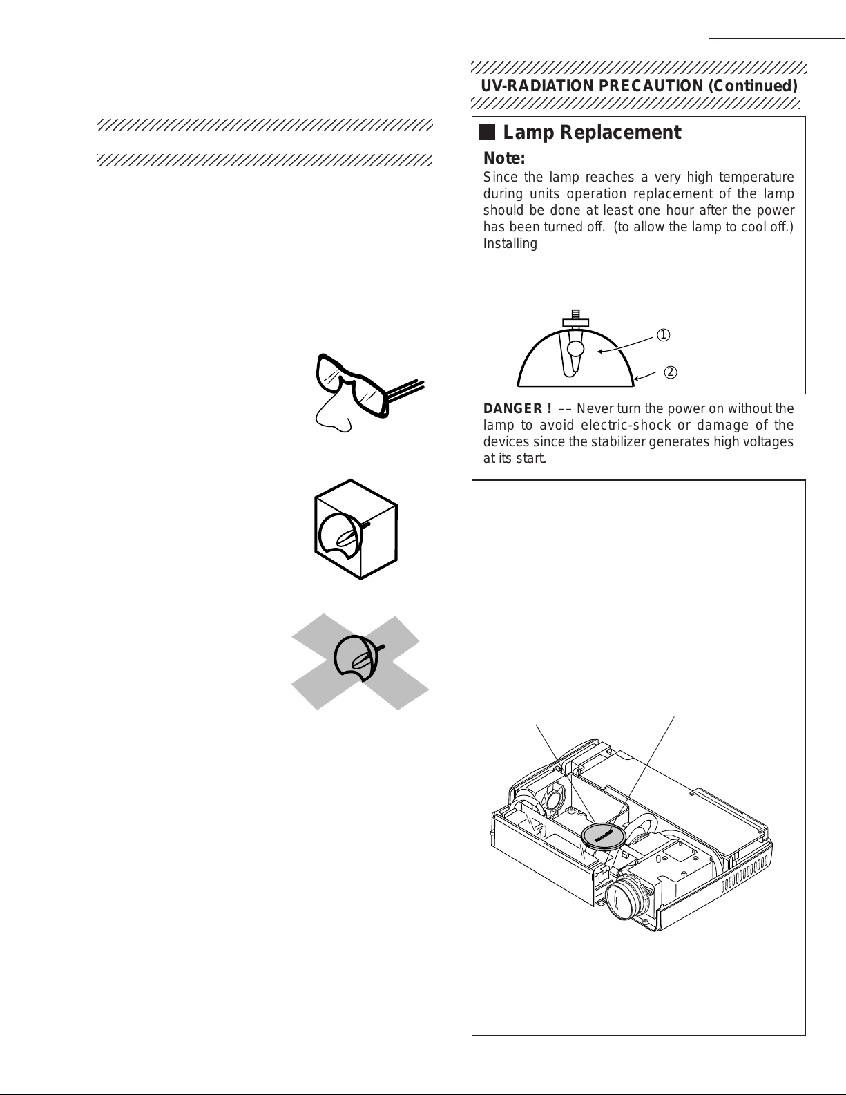
UV-RADIATION PRECAUTION (Continued)
Lamp Replacement
Note:
Since the lamp reaches a very high temperature
during units operation replacement of the lamp
should be done at least one hour after the power
has been turned off. (to allow the lamp to cool off.)
Installing the new lamp, make sure not to touch the
lamp (bulb) replace the lamp by holding its reflector
2.
[Use original replacement only.]
Lamp
1
Reflector
2
DANGER ! –– Never turn the power on without the
lamp to avoid electric-shock or damage of the
devices since the stabilizer generates high voltages
at its start.
3. Do not operate for more than 2 hours with the
enclosure removed.
UV-Radiation and Medium Pressure
Lamp Precautions
1. Be sure to disconnect the AC plug when replacing
the lamp.
2. Allow one hour for the unit to cool down before
servicing.
3. Replace only with same type lamp. Type BQCPGM10X//-1 rated 85V/130W.
4. The lamp emits small amounts of UV-Radiation, avoid
direct-eye contact.
5. The medium pressure lamp involves a risk of
explosion. Be sure to follow installation instructions
described below and handle the lamp with care.
Since small amounts of UV-Radiation are emitted
from an opening between the duct cover and the
lamp housing, it is recommended to place the LENS
CAP on the opening during servicing to avoid eye
and skin exposure (Fig. 1).
Notes:
» Please obtain a lens cap before servicing a model
PG-M10SU/SE, PG-M10XU/XE that is received
without one.
» The color wheel is running at high speed. Do not
touch it nor bring anything nearby.
COLOR WHEEL LENS CAP
Figure 1.
3
Page 4

PG-M10SU/SE
PG-M10XU/XE
Location of Controls
4
Page 5

PG-M10SU/SE
PG-M10XU/XE
5
Page 6

PG-M10SU/SE
PG-M10XU/XE
Reomte Control
6
Page 7

Connections
PG-M10SU/SE
PG-M10XU/XE
7
Page 8

PG-M10SU/SE
PG-M10XU/XE
8
Page 9

Pin Assignments
PG-M10SU/SE
PG-M10XU/XE
Dimensions
9
Page 10

PG-M10SU/SE
PG-M10XU/XE
DISASSEMBLY AND REASSEMBLY
1.Preparations and precautions
● Tools required
1. Phillips screwdriver, Nos. 1 and 2
2. Phillips and bladed precision screwdrivers
3. Anti-static wrist band
4. Hexagonal wrench (opposite side: ___ mm)
● Precautions for disassembly and reassembly
1. Before starting the procedure, unplug the power cable.
2. Some parts are still hot immediately after operation. Wait until they have cooled down.
3. Restore the components, screws and wires in their original positions.
4. Follow the important notes in handling the components and carrying out the job.
5. Be careful not to confuse the specific component parts for different models.
6. Do not tamper with the unit to ensure safety.
2.Disassembly and reassembly
1) Front panel (See Fig. 1 and Fig. 1-A.)
Remove the two screws (S-8) shown in Fig. 1.
Remove the front panel as shown in Fig. 1-A.
Note: Take care not to damage the IR cable.
2) Top cover (See Fig. 2.)
Remove the two louver screws (S-8) shown in Fig.
2.
Remove the top cover as shown in Fig. 2.
Note: Take care not to damage the speaker cable.
Top Cover
S-8
Fig. 1
2
Louver
Screw
S-8
Louver
Screw
Fig. 2
1
Front Panel
Fig. 1-A
10
Page 11

PG-M10SU/SE
PG-M10XU/XE
3) Speaker, buttons, etc. (See Fig. 3.)
As shown in Fig. 3, remove the nuts, speaker button
OP, and LED lens. Undo the hooks and remove
front buttons.
Speaker Ass’y
Front Foot
S-25
LED
Lens
Button
OP
S-25
Top Cover
5) Disassembling the front panel (See Fig. 5.)
Remove the screw (S-12) shown in Fig. 5, and
detach the front door.
Remove the screw (S-4) and take out the IR PWB.
Remove the two screws (S-1) and detach the plates.
Remove the screw (S-4) each off the right and left
front hooks, and detach the hooks.
S-4
S-18
Front Door
S-12
S-1
S-4
S-4
Fig. 3
4) Insulation barrier, urethane foam shield, etc. (See
Fig. 4.)
As shown in Fig. 4, the front cabinet is lined with
the barrier sheet.
Top Cover
Fig. 5
6) F/E PWB (See Fig. 6.)
Remove the screw (S-13) and two screws (S-5)
shown in Fig. 6, and disconnect the connectors.
Remove the screw (S-13) and two RGB spacers,
and detach the connector panel.
S-13
S-23
S-5
S-23
S-13
RGB Spacer
S-5
S-23
F/E PWB
Connector
Panel
Fig. 4
Fig. 6
11
Page 12

PG-M10SU/SE
PG-M10XU/XE
7) Lamp driver (See Fig. 7.)
Remove the two screws (S-16 and S-17 each)
shown in Fig. 7, and dismount the lamp driver.
S-16
S-19
Lamp Driver
S-17
Fig. 7
8) Lens base (See Fig. 8.)
Remove the four screws (S-7) shown in Fig. 8, and
detach the lens base.
Note: When disassembling or reassembling, be careful
not to get the wires caught. Do not dismount
the spherical mirror and the cylinder mirror out
of the lens base. Otherwise the adjustment will
be lost to produce shadows at the corners of
the screen.
S-7
9) Heat sink (See Fig. 9.)
Remove the two screws (S-1 1) shown in Fig. 9, and
detach the heat sink.
Note: Be careful to fit the heat sink in the correct
direction.
Heat Sink A
S-11
Heat Sink B
Fig. 9
10)DMD and F/M PWB (See Fig. 10.)
Remove the four screws (S-9) shown in Fig. 10,
and detach the DMD and F/M PWB from the lens
base.
Note: Take care not to touch the elastomer, DMD
surface or terminals, and F/M PWB terminals
by finger. When reassembling, be careful not to
allow dust or dirt on the parts. Special care
should be taken in handling the DMD, elastomer
and F/M PWB, which will directly affect the image
quality .
Fig. 8
S-7
S-7
Lens Base
12
F/M PWB
DMD
Elastomer
Fig. 10
F/M Angle
Elastomer
Holder
S-9
Page 13

11)Projection lens (See Fig. 11.)
Wheel Cover
Wheel Sensor
S-4
Light Tunnel
Aperture
S-4
S-7
S-7
Remove the three screws (S-7) shown in Fig. 11,
and detach the projection lens.
Note: When reassembling, be careful not to damage
the spherical mirror inside of the lens base.
S-7
PG-M10SU/SE
PG-M10XU/XE
Projection lens
S-7
Fig. 11
12)Color wheel (See Figs. 12 and 13.)
Remove the two screws (S-9) shown in Fig. 12, and
detach the color wheel from the lens base.
Remove the two screws (S-4) shown in Fig. 13, and
detach the wheel cover from the color wheel.
Remove the wheel screw shown in Fig. 13, and
detach the wheel sensor.
Note: When reassembling, be careful not to tighten
the screws too much. Otherwise the color wheel
mat come in contact with other components
nearby and fail to rotate. Readjustment will be
needed if the color wheel and the wheel sensor
have been replaced. (Refer to page __.)
Fig. 13
13)Light tunnel and aperture (See Fig. 14.)
Remove the three screws (S-7) shown in Fig. 14,
and detach the light tunnel from the lens base.
Remove the two screws (S-4) shown in Fig. 14, and
detach the aperture from the lens base.
Note: Do not disassemble the light tunnel.
Fig. 12
Color wheel
S-9
Fig. 14
S-9
13
Page 14

PG-M10SU/SE
PG-M10XU/XE
14)Lamp housing (See Fig. 15.)
Remove the three screws (S-7) shown in Fig. 15,
and detach the lamp housing from the bottom cover .
Remove the screws (S-15) shown in Fig. 15, and
detach the thermistor and thermistor plate.
Remove the screw (S-7) shown in Fig. 15, and
detach the ballast lock base.
With the lamp housing taken out, the 40 fan
assembly (DC) can be detached.
Note: Take note of the wiring for the 40 fan assembly ,
which goes below the lamp housing.
40FAN(DC)
S-7
S-7
Lamp housing
S-15
Thermistor
Ass’y
Thermistor
Plate
S-15
16)Front and rear feet (See Fig. 17.)
As shown in Fig. 17, press the hook (1) first and
then the hook (2). Remove the front feet.
Turn the rear feet away out of place.
Remove the screw (S-7) shown in Fig. 17, and
detach the lamp limit switch.
S-7
Rear Foot
Front Foot
Lamp Limit
Switch
Fig. 15
15)Power unit (See Fig. 16.)
Remove the two screws (S-7) shown in Fig. 16, and
detach the fan base from the cover.
Remove the screws (S-5 and S-10 one each) and
the two D/M spacers shown in Fig. 16, and detach
the power unit.
S-5
D/M Spacer
Power Unit
40FAN(L)
S-7
Fan Base
S-10
S-7
Fig. 17
Fig. 16
14
Page 15

REPLACING THE LAMP
● Tools required
1. A soft sheet on which the projector is placed upside down. It is to protect the unit against scratches.
2. Phillips screwdriver No. 1
● Precautions in replacing and handling the lamp
1. Be sure to unplug the power cable before starting the procedure. (For prevention of electric shock)
2. Make sure that the lamp has cooled down before replacement. (For prevention of burns)
3. Do not give intense shock or vibration to the lamp. (For prevention of breakage and injury)
4. Do not disassemble the lamp.
● Replacement procedure
1) Remove the screw off the lamp cover.
5) Install a new lamp unit into position.
PG-M10SU/SE
PG-M10XU/XE
2) Detach the lamp cover.
3) Remove the three screws off the lamp unit.
4) Take out the lamp unit by holding its grip.
6) Tighten up the three screws in the lamp unit.
7) Mount the lamp cover and fix it with the screw.
8) Reset the total lamp timer.
●Select the lamp time menu, and keep pressing the
POWER ON button of the remote controller for 10
seconds or longer.
15
Page 16

PG-M10SU/SE
PG-M10XU/XE
BLOCK DIAGRAM OF OPTICAL SYSTEM PRINCIPLE
1
●Names of parts and operating specifications
1 Lamp
2 RGBW color filter
G B R W
2
3
6
7
5
4
The AC light source lamp flickers 300 times per second.
This color filter splits the light into RGB and W components.
The W (White) component contributes to the reproduction
of bright white color. The rotation-detecting sensor should
get in sync with the timing to turn off the lamp at the seam
of color filter. The maximum rotating speed is 7200 rpm.
3 Condenser lens and light tunnel
4 Reflection mirror 1 & 2
5 DMD chip
6 Projection lens
7 Screen
This lens condenses the light that is split in RGB and W
components by the color filter, and projects it to the
effective area of the reflection mirror 1. Adoption of the
light tunnel has enhanced the illuminance ratio in
peripheral area of image, reducing the difference in
brightness between screen center and peripheries. The
image can be reproduced clearly at every corner of the
screen.
This mirror reflects the light projected to the effective area
of the DMD.
This chip turns on and off in proportion to each color
component per dot depending on the input source.
This lens enlarges and projects the incident light coming
from the DMD.
Projected light (RGB and W components) is interpreted
by the viewer's eye as composite color image due to afterimage phenomenon.
16
Page 17

OPTICAL ADJUSTMENT AND MEASURING
Wheel Screw
Wheel Sensor
1.Adjustment of color wheel sensor
● Adjustment needed
1. When the color wheel unit has been replaced
2. When the color wheel sensor has been replaced
3. When the optical drive unit has been replaced (if a deviation from normal setting is found)
4. When the F/E PWB has been replaced (if a deviation from normal setting is found)
● Tools required
1. Personal computer (run on Windows 95/98)
2. RGB cable
3. Dedicated application program (white.exe program commonly used for both models UP and U2)
4. Wrench (5 mm)
5. Projection screen (normally white)
Note: During the adjustment, be careful not to touch the lamp and other hot components.
● Procedure
1. Adjustment should be done with the top cover and
the front panel removed.
2. Connect the projector to the PC (RGB mode).
3. Start up the dedicated application program
(white.exe) on the PC.
4. Press the "6" key on the keyboard. After the pattern
shown in Fig. 1 at right has appeared, press the
"R" key to get the red image displayed for checking.
Check the other colors as well (*1).
5. When part of the image does not appear in red,
loosen the wheel screw shown in Fig. 2 below and
slide the wheel sensor up or down. Fix the wheel
sensor again at the position where the color
deviation disappears.
6. Finally press the "Q" key on the keyboard to finish
the program.
Fig.1
PG-M10SU/SE
PG-M10XU/XE
Fig.2
●1:The basic black and white patterns are registered in the numeric keys 0 thru 9 on the keyboard. The colors can be
changed to any of White(W), Black(K), Red(R), Green(G), Blue(B), Magenta(M) and Cyanic(C).
17
Page 18

PG-M10SU/SE
PG-M10XU/XE
2.Measuring illuminance
● Tools required
1. Personal computer (run on Windows 95/98)
2. Projection screen (normally white)
3. Light distribution point display program (Lumens.exe program commonly used for both models UP and U2)
4. Illumination meter
● Measuring lumen value
Connect the projector to the PC, and starts lighting.
Start up the light distribution point display program
(Lumens.exe) on the PC. Make the room dark. (A
darkroom is recommended.) Measure the illuminance
at the nine points shown at right. Put the measured
illuminance into the following equation to obtain the
lumen value.
A
B
Lumen value (L) = (Average illuminance of 9 points) x (Projected area in m2)
={(P1+P2+ • • • +P9) / 9} x (A xB)
● Evenness of illuminance
Put the measured illuminance into the following equation to obtain the evenness of illuminance.
Evenness of illuminance (%) = (The lowest illuminance measured out of 9 points) / (Average illuminance of 9 points)
= [MIN.(P1~P9) / {(P1+P2+ • • • +P9) / 9}] x 100
● Peripheral illuminance ratio
Put the measured illuminance into the following equation to obtain the peripheral illuminance ratio.
Peripheral illuminance ratio (%) = (Average illuminance at P1, P3, P7 and P9) / (Illuminance at P5)
= {(P1+P3+P7+P9) / 4} / P5] x 100
The factory settings are as follows.
Model PG-M10X
Lumen value: Min. 500 Lm Evenness of illuminance: Min. 50% Peripheral illuminance ratio: Min. 80%
Model PG-M10S
Lumen value: Min. 500 Lm Evenness of illuminance: Min. 50% Peripheral illuminance ratio: Min. 80%
18
Page 19

3.Precautions in disassembling the optical mechanism
DMD assembly
Color wheel
Once disassembled, this part may
need readjustment.
This assembly can be disassembled. But be careful not to allow dust and fingerprint on it. Otherwise
the images may be adversely affected.
PG-M10SU/SE
PG-M10XU/XE
Condenser lens ass'y
If the condenser lens or mirror has not
been correctly adjusted, there will be
shades on the projection screen.
(Usually shades appear on the righthand edge or at the bottom right corner of the screen.)
Spherical
mirror
Do not separate the spherical
mirror and cylinder mirror from
the lens base (46).
Cylinder mirror
19
Page 20

PG-M10SU/SE
PG-M10XU/XE
SAFETY DEVICE
1.Internal temperature detection
The lamp housing has a built-in thermostat which puts out the lamp when the temperature becomes 110°C.
Similarly , the power supply unit and lamp driver have thermostats which terminate power supply and driver operation
when the temperature reaches 120°C and 115°C, respectively.
2.Lamp unit interlocking switch
The lamp will not light up unless the lamp cover is mounted.
3.Fault-finding status LED indicator
When the lamp fails to light up, the status LED indicator starts flickering. Different flickering intervals help identify
the cause. (Refer to the figure at right and the table below.)
LED condition Meaning Correction
OFF (kept off)
ON (kept on)
Flickers with a cycle of one
second (0.5 sec. ON and
0.5 sec. OFF)
Flickers with a cycle of 4
seconds (2 sec. ON and 2
sec. OFF)
Flickers with a cycle of 8
seconds (4 sec. ON and 4
sec. OFF)
Normal condition
Total lamp timer has exceeded
1000 hours.
Lamp cover is not mounted cor-
rectly .
Temperature protector is activated.
Temperature protector still activated. Power may fail to come
on if the main power switch is
turned on just after it has turned
off.
Lamp light-up voltage error detector is activated.
Fan is nor running.
Replace the lamp with new one, and reset the
total lamp timer.
Mount the lamp cover correctly.
If room temperature is too high, relocate the projector to cooler area. If the projector's internal
temperature rises abnormally, check the cooling fan vent hole and the unit's bottom vent hole.
Clean them if they are clogged.
Wait for one minute, and try again to turn on the
power switch.
Wait for one minute, and try again to turn on the
power switch.
Check the fan.
Flickers with a cycle of 12
seconds (6 sec. ON and
6sec. OFF)
Lamp fails to light up.
Wait for one minute or longer, and try again to
turn on the power switch. Make internal check
if the condition is not improved.
20
Page 21

TROUBLESHOOTING TABLE
1.Troubleshooting in general
Symptom Possible causes Correction
PG-M10SU/SE
PG-M10XU/XE
Power is not supplied.
The unit does not go into
stand-by mode.
Image does not appear.
Lamp does not light up.
(Status LED indicator
flickers.)
Image does not appear.
Lamp is on.
Image is distorted.
Image is blurred.
Image is dislocated either horizontally or
vertically.
Remote controller is
not working.
Wireless mouse does
not work.
Status indicator LED
flickers.
Characters flitter or
colors deviate with
RGB input.
1.Power cable not connected to power
outlet.
2.Power cable damaged.
3.No power supplied to power outlet.
1.Lamp blown out.
2. Total lamp time exceeding 1100
hours.
3.Lamp cover not mounted correctly.
4.Protector circuit activated due to high
internal temperature.
1.Incorrect input selection.
2.Incorrect cable connection.
3.Cable disconnected or connector pin
broken.
4.Brightness or contrast set to
minimum.
5.Closed shutter.
6. Turning on PC power switch before
connecting to the projector when
notebook PC is used.
1.Incorrect placement of the projector.
1.Lens out of focus.
2.Incorrect angle between the
projection screen and the projector.
3. Projection distance out of the range
for correct focusing.
4.Dew condensation on the lens.
5.Stained lens or optical unit.
1.Screen's horizontal or vertical position
maladjusted.
2.Clock frequency maladjusted.
3.Resolution and frequency not
corresponding to input signal.
1. Does signal transmission indicator
(LED) flicker? If no flickering,
batteries are dead. Even when the
indicator flickers, signal transmission
may be ineffective due to low battery
voltage.
2.Obstruction between the remote
controller and receiver on the
projector.
3. Operation out of effective range of
remote controller.
4. Intense light or fluorescent lamp
existing near the receiver.
1. Wrong connection between the PC
and the projector's mouse terminal.
2. PC started up before connecting to
the projector's mouse terminal.
1. Refer to the description for the status
LED (on page 20).
1.Poor adjustment in AUTO mode.
2.Adjustment made in MANU mode.
1.Connect the power cable correctly.
2.Replace the power cable.
3.Check the circuit breaker.
1.Replace the lamp.
2.Replace the lamp, and reset the total lamp timer.
3.Mount the lamp cover correctly.
4. Check the operating environment. Check to see if
the vent holes are not blocked.
1.Select the correct input.
2.Check the cable connection.
3.Replace the cable.
4.Make adjustment with the program menu.
5.Open the shutter.
6.First hook up the PC to the projector and then turn
on the PC power.
1.Check the placement condition.
1.Adjust focus with the focus ring.
2.Set the screen and the projector lens at right angles.
3. Make the projection distance within the range for
correct focusing.
4.Wait until dew condensation disappears.
5.Clean the lens or optical unit.
1.Make adjustment with the program menu.
2.Manually adjust the clock frequency and phase.
3.Check the PC's resolution setting.
1.Replace the batteries with new ones.
2.Remove obstruction or change the operation
position.
3.Use the remote controller within its effective range.
4. Relocate the projector to a place not affected by
intense light, or turn off the light.
1.Check the connection.
2.Start up the PC after connection.
1.Check the flickering intervals and take proper
measures.
1.Manually adjust the clock frequency and phase.
2.Press the AUTO button.
21
Page 22

PG-M10SU/SE
B
A
C
D
E
F
1 2 3 4 5 6 7 8 9 10
PG-M10XU/XE
Ref. No. Part No. ★ Description Code Ref. No. Part No. ★ Description Code
BLOCK DIAGRAM / BLOCKSCHALTBILD
SPEAKER
IR-SENSOR
PORM
POPA
POSP
CN20
CN2
CN1
COLOR
DC
WHEEL
POWER
F/E PWB
SUPPLY
UNIT
PODC
PODB
POLB
POLA
PODA
WHEEL-SENSOR
LAMP
DRIVER
LAMP-SW
LAMP
POFA
POFB
TEMPERTURE
-SENSOR
J2
RAMP
-FAN
DV-PSU
-FAN
43
F/M PWB
Page 23

PG-M10SU/SE
PG-M10XU/XE
Ref. No. Part No. ★ Description Code Ref. No. Part No. ★ Description Code
PARTS LIST
ERSATZTEILLISTE
PARTS REPLACEMENT
Parts marked with "å" are important for maintaining the safety of
the set. Be sure to replace these parts with specified ones for maintaining the safety and performance of the set.
Les pieces marquées "å" sont importantes pour maintenir la sécurité
de l'appareil. Ne remplacer ces pieces que par des pieces dont le
numéro est spécifié pour maintenir la sécurité et protéger le bon
fonctinnement de l'appareil.
"HOW TO ORDER REPLACEMENT PARTS"
To have your order filled promptly and correctly, please furnish the
following informations.
1. MODEL NUMBER 2. REF . NO.
3. PART NO. 4. DESCRIPTION
5. CODE 6. QUANTITY
in USA: Contact your nearest SHARP Parts Distributor.
For location of SHARP Parts Distributor,
Please call Toll-Free; 1-800-BE-SHARP
in CANADA: Contact SHARP Electronics of Canada Limited
Phone (416) 890-2100.
★ MARK: SPARE PARTS-DELIVERY SECTION
AUSTAUSCH VON TEILEN
Ersatzteile, die besondere Sicherheitseigenschften haben, sind in
dieser Anleitung markiert. Elektrische Komponenten mit solchen
Eigenshaften sind in den Ersatzteil durch "å" gekenn-zeichnet.
Der Gebrauch von Ersatzteilen, die nicht deselben Sicherheitseigenschaften haben wie die vom Hersteller empfohlenen ud in der
Bedienungsanleitung angegebenen, können zur Ursache von
Blitzeinschlägen, Bränden und anderen Gefahren werden.
"WIE MAN ERSATSTEILE BESTELLT"
Damit Ihre Bestellung promt und korrekt ausgeführt wird, geben Sie
bitte folgende Informationen.
1. MODELL NR. 2. REF . NR.
3. ERSATZTEIL NR. 4. BESCHREIBUNG
5. KODE 6. QUANTITÄT
★ MARKIERUNG : ERSATZTEILE-LIEFERUNG
Ref. No. Part No. ★ Description Code
PRINTED WIRING BOARD ASSEMBLIES
(UNIT REPLACEMENT ITEM)
9FU770503000 J IR Sensor Unit AZ
9FU770821500 J F/E Unit (PG-M10X) DU
9FU770821600 J F/E Unit (PG-M10S) DU
9FU770508000 J Lamp Driver Unit CW
9FU770507000 J DC Power Supply Unit CV
CABINET AND MECHANICAL PARTS
1 9FU770821210 J Top Cover Ass’y (PG-M10S) CC
1 9FU770820310 J Top Cover Ass’y (PG-M10X) CC
2
3
4
5
6
7
8
9
10
11
12
13
14
15
16
17 9FU770519000 J Speaker Ass’y BA
Not Available
Not Available
Not Available
Not Available
Not Available
Not Available
Not Available
Not Available
Not Available
Not Available
Not Available
Not Available
Not Available
Not Available
Not Available
TOP CABINET SECTION
– Top Cover —
– Button OP —
– LED Lens —
– Foot Button —
– Foot Button Spring —
– Sensor Cover R —
– Insulation Board —
– Heat Conductive Both —
Sides T ape S
– Heat Conductive Both —
Sides T ape B
– Insulation Board Friction —
Tape
– Insulation Board Spacer —
– Top Cover Urethane Form L —
– Top Cover Mesh —
– Insulation Sheet F/E —
– U3 Gasket —
Ref. No. Part No. ★ Description Code
18 9FU770821300 J Front Panel (PG-M10S) BT
18 9FU770820500 J Front Panel (PG-M10X) BT
19 9FU177032504 J Slider Plate AL
20 9FU770326000 J Slider Spring (1) AD
21 9FU770328000 J Slider Spring (2) AD
22 9FU770327000 J Slider Holder AE
23 9FU177041806 J Push Slider AN
24 9FU770503000 J IR PWB AZ
25 9FU770511000 J IR Cable Ass’y AL
26 9FU770408000 J Front Hook (1) AF
27 9FU770409000 J Front Hook (2) AF
28 9FU770821410 J Front Door Ass’y (PG-M10S)BG
28 9FU770820610 J Front Door Ass’y (PG-M10X) BG
29
30
31
32
33 9FU770329000 J Louver Screw AD
34 9FU770413000 J Spacer D/M AH
Not Available
Not Available
Not Available
Not Available
– Front Door —
– Front Door Slide Sheet (1) —
– Front Door Slide Sheet (2) —
– Front Door Reflect Sheet —
44
Page 24

PG-M10SU/SE
PG-M10XU/XE
Ref. No. Part No. ★ Description Code Ref. No. Part No. ★ Description Code
J
1
2
I
H
G
10
12
14
9
15
11
34
5
6
S-8
7
4
16
3
S-20
S-8
17
F
13
S-1
8
S-20
E
33
S-7
D
18
C
28
S-8
B
27
22
S-22
19
21
S-12
23
26
20
S-2
S-4
25
S-7
S-8
32
29
30
A
31
S-8
24
1 2 3 4 5 6 7 8 9 10
45
Page 25

PG-M10SU/SE
PG-M10XU/XE
Ref. No. Part No. ★ Description Code Ref. No. Part No. ★ Description Code
CABINET AND MECHANICAL PARTS
(Continued)
PWB Section
35 9FU770821600 J F/E PWB (PG-M10S) DU
35 9FU770821500 J F/E PWB (PG-M10X) DU
36 9FU770820800 J Connector Panel AY
37 9FU770820900 J Connector Sheet AG
38 9FU770415000 J Spacer RGB AH
39 9FU770426000 J Lens Base Urethane Form AC
40 9FU770414000 J Lamp Driver Stud AM
41 9FU770505000 J Limit SW Board Ass’y AZ
42 9FU770508000 J Lamp Driver-U CW
43 9FU770802600 J Insulate Sheet L/D-N BB
45 9FU770407000 J Lamp Driver Lodk Base AG
46 9FU770821000 J Louver Panel AY
56
58
F
57
S-7
S-3
55
47 9FU770417100 J Lamp House Ass’y-U BC
48
49
50
51
52
Not Available
Not Available
Not Available
Not Available
Not Available
– Lamp House-U —
– Lamp House Mesh —
– Lamp House Guard —
– Insulation Varrier —
– Lamp House Mesh Tape —
53 9FU770814700 J Lamp fan Spacer AL
54 9FU770821700 J Thermistor Ass’y AR
55 9FU770814600 J 40 Fan Ass’y L-H BK
56 9FU770517000 J 40 Fan Ass’y DC BK
57 9FU770412000 J Fan Cushion AD
58 9FU770405000 J Fan Vibration Proof Rubber AC
59 9FU770406000 J Fan Guard AD
60 9FU770402000 J Fan Base AH
61 9FU770524000 J Core AR
62 9FU177044200 J Fan Fence AG
63 9FU770522000 J Ground Lead AG
62
S-7
60
S-13
S-18
63
S-5
35
S-18
S-13
38
37
36
E
S-7
61
59
53
D
S-7
46
48
52
47
52
49
41
S-7
50
S-5
54
S-16
51
S-7
39
S-7
C
45
40
S-7
S-7
B
43
44
A
S-17
42
1 2 3 4 5 6 7 8 9 10
46
Page 26

PG-M10SU/SE
B
A
C
D
E
F
1 2 3 4 5 6 7 8 9 10
PG-M10XU/XE
Ref. No. Part No. ★ Description Code Ref. No. Part No. ★ Description Code
CABINET AND MECHANICAL PARTS
(Continued)
BOTTOM COVER SECTION
64 9FU770820400 J Bottom Cover BW
65 9FU177043004 J Inlet Spacer AL
66 9FU770413000 J Spacer D/M AH
67 9FU770826800 J Spacer Tube AD
68 9FU770507000 J DC Power Unit CV
69 9FU770825000 J Insulation Sheet DC-1 BB
70 9FU770825200 J Insulation Sheet DC-2 BB
71 9FU770424000 J Insulation Sheet DC-3 AH
72 9FU770314000 J Rear Foot AL
73 9FU770320000 J Rear Foot Rubber AF
74 9FU770322000 J Front Foot BA
75 9FU770820710 J Lamp Cover Ass’y BC
76
77
78
79
80 BQC-PGM10X//1 J Lamp Ass'y CS
Not Available
Not Available
Not Available
Not Available
– Lamp Cover —
– Lamp Cover Screw —
– Lamp Cover Screw Spring —
– Lamp Cover Guard —
65
S-10
66
67
S-21
S-5
70
66
69
71
68
72
73
73
64
80
S-19
79
75
74
78
76
77
73
47
Page 27

PG-M10SU/SE
PG-M10XU/XE
Ref. No. Part No. ★ Description Code Ref. No. Part No. ★ Description Code
CABINET AND MECHANICAL PARTS
(Continued)
OPTICAL SECTION
81 9FU770800000 J Lens Base Ass’y CM
82
83
84
85
86
87
88 9FU770801900 J Insulation Sheet LB-U AN
89 9FU770800100 J Projection Lens Unit CR
F
E
Not Available
Not Available
Not Available
Not Available
Not Available
Not Available
95
94
– Lens Base —
– Spherical Mirror —
– Cylinder Mirror —
– Aparture —
– Lens Base Cover —
– Lens Base Sheel —
S-14
92
90 9FU770157000 J Condenser Lens Ass’y CD
91 9FU770130000 J Colour Wheel Ass’y CE
92 9FU770139000 J Wheel Cover AQ
93 9FU770140000 J Rubber Sheet BB
94 9FU770504000 J Wheel Sensor Board Ass’y AZ
95 9FU770416000 J Wheel Screw AD
96 9FU770439000 J Wire Sticker SD-10 AD
97 9FU770551000 J DMD Set, 97-A~D GE
97 9FU770510000 J DMD Set, 97-A~D HL
98 9FU177041004 J Push F/M Board AL
99 9FU177040303 J Heat Sink A AG
100 9FU177040403 J Heat Sink B AG
97-D
(PG-M10S)
(PG-M10X)
97
91
S-4
93
S-7
96
D
90
S-7
C
88
S-7
B
89
S-7
83
S-9
87
97-A
86
82
84
97-C
97-B
85
S-7
81
98
S-9
S-11
100
99
A
1 2 3 4 5 6 7 8 9 10
48
Page 28

PG-M10SU/SE
B
A
C
D
E
F
1 2 3 4 5 6 7 8 9 10
PG-M10XU/XE
Ref. No. Part No. ★ Description Code Ref. No. Part No. ★ Description Code
CABINET AND MECHANICAL PARTS
(Continued)
Label Section
101 9FU770821900 J Standard Label (PG-M10S) AQ
101 9FU770821800 J Standard Label (PG-M10X) AQ
102 9FU770822000 J Hot Caution Label AD
105
102
103 9FU770822100 J Lens Attention Indication AE
Plate
104 9FU770822200 J Lamp Caution Sheel A AF
105 9FU770824000 J Hot Caution Sheel 3 AD
106 9FU770824100 J Thunder Caution Indication AD
Plate
107 9FU770826700 J Attention Indication Board AE
(Swedish)
103
101
105
106
104
107
49
Page 29

PG-M10SU/SE
PG-M10XU/XE
Ref. No. Part No. ★ Description Code Ref. No. Part No. ★ Description Code
SCREWS, NUTS AND WASHERS
S-1 9FU957620020 J Washer, x1 AB
S-2 9FU951122551 J Screw, x4 AB
S-3 9FU953930650 J Screw, x1 AB
S-4 9FU951220450 J Screw, x4 AB
S-5 9FU952320430 J Screw, x3 AB
S-6 9FU952320450 J Screw, x1 AB
S-7 9FU951220550 J Screw, x27 AB
S-8 9FU951220430 J Screw, x5 AB
S-9 9FU951220830 J Screw, x7 AB
S-10 9FU952140510 J Screw, x1 AB
S-11 9FU959161220 J Screw, x2 AC
S-12 9FU953120351 J Screw, x1 AB
S-13 9FU953220530 J Screw, x2 AB
S-14 9FU951221010 J Screw, x1 AB
S-15 9FU953226510 J Screw, x1 AB
S-16 9FU953230650 J Screw, x1 AB
S-17 9FU951630550 J Screw, x1 AC
S-18 9FU957220530 J Washer, x2 AB
S-19 9FU958440200 J Cut Washer, x1 AB
S-20 9FU958615000 J Push Nut, x9 AB
S-21 9FU957240810 J Washer, x1 AB
S-22 9FU957220650 J Washer, x3 AB
SUPPLIED ACCESSORIES
108 9FU770822600 J Packing Case (PG-M10S) AQ
108 9FU770822500 J Packing Case (PG-M10X) AQ
109 9FU770612000 J Sleeve AW
110 9FU770824800 J Polyethylene Bag AG
111 9FU770611000 J Accessory Box AM
112 9FU753321500 J Bag (for Operation Manual AC
113 9FU770822800 J Operation Manual BD
114 9FU770822900 J Quick Start Guide AG
115 9FU770825700 J User Registration Form AH
115 9FU770826300 J User Registration Form (for AG
115 9FU770826400 J User Registration Form (for AG
116 9FU770823000 J Warranty Card AL
116 9FU770825800 J Warranty Card (for USA) AE
116 9FU770826100 J Warranty Card (for AE
117 9FU770826500 J Bag (for Card) AG
117 9FU770825500 J Envelope (for USA) AF
117 9FU770826200 J USA Label AD
117 9FU770825900 J Sticker (for USA) AG
117 9FU770825600 J User Guide Line (for USA) AG
117
117
118 9FU770823200 J Carrying Case BQ
119 9FU770625000 J Accessory Pad AF
120 9FU770823400 J Inner Case BA
121 9FU770823300 J Remote Controller BX
122 9FU770822400 J Remote Controller Label AH
123
124 9FU770726000 J AC Cord (1.8m) for USA AW
124 9FU770727000 J AC Cord (1.8m) for Europe AX
124 9FU770728000 J AC Cord (1.8m) for UK BA
124 9FU770729000 J AC Cord (1.8m) Australia AX
124 9FU770826600 J AC Cord Attention Label AF
125 9FU770703000 J Viideo Cable (1P 1m) AN
126 9FU770704000 J Audio Adapter AS
127 9FU770709000 J S-Video Cable (1m) AR
128 9FU770708000 J RGB Cable (1m) BB
129 9FU770710000 J MINI Jack Cable (1m) AP
130 9FU770706000 J PS/2 Mouse Cable AS
131 9FU770707000 J USB Mouse cable AS
Not Available
Not Available
Not Available
(for Machine)
and Accessories)
(for USA)
Canadian English area)
Canadian French area)
Canadian English area)
– No. Card —
– Carton Label —
– Batteries —
and Canada
50
Page 30

PG-M10SU/SE
PG-M10XU/XE
Ref. No. Part No. ★ Description Code Ref. No. Part No. ★ Description Code
PACKING OF THE SET / VERPACKEN DES GERÄTS
131
130
128
126
127
121
PLUS
112
125
122
123
129
124
112
113
114
115
116
117
120
119
108
109
118
111
110
109
51
Page 31

PG-M10SU/SE
PG-M10XU/XE
Ref. No. Part No. ★ Description Code Ref. No. Part No. ★ Description Code
COPYRIGHT © 2000 BY SHARP CORPORATION
ALL RIGHTS RESERVED.
No part of this publication may be reproduced,
stored in a retrieval system, or transmitted in
any form or by any means, electronic, mechanical,
photocopying, recording, or otherwise, without
prior written permission of the publisher.
DJapan PJapanTQ0986-S
Sept. 2000 Printed in Japan
In Japan gedruckt
SY. KY
SHARP CORPORATION
AV Systems Group
Quality & Reliability Control Center
Yaita, Tochigi 329-2193, Japan
52
 Loading...