

Page 1

DATA PROJECTOR
MODEL
PG-D40W3D
SETUP MANUAL
Connecting Pin Assignments .............................. 2
RS-232C Specifi cations and Commands ........... 4
Setting up the Projector Network Environment
1. Connecting the Projector to a Computer ...........11
2. Setting an IP Address for the Computer ............12
3. Setting up a Network Connection for the
Projector .......................................................14
Controlling the Projector via LAN ..................... 16
Controlling the Projector Using Internet Explorer
(Version 5.0 or later)......................................16
Confi rming the Projector Status (Status) ................17
Controlling the Projector (Control) ..........................17
Setting and Adjusting the Projector
(Settings & Adjustments) ..............................18
Setting the Security (Network – Security) ...............18
Making General Settings for the Network
(Network – General) .....................................19
Setting for Sending E-mail when an Error Occurs
(Mail – Originator Settings) ..........................19
Setting Error Items and Destination Addresses
to which E-mail is to be Sent when an
Error Occurs (Mail – Recipient Settings) ......20
Setting Error Items and the URL that are to be
Displayed when an Error Occurs
(Service & Support – Access URL) ...............20
Setting up the Projector Using RS-232C or
Telnet .......................................................... 21
When Connecting Using RS-232C .........................21
When Connecting Using Telnet ..............................22
SETUP MENU (Main Menu) ....................................23
ADVANCED SETUP MENU ....................................23
View Setting Detail List ([V]View All Setting) ...........24
Set Items ................................................................24
Save Settings and Quit ([S]Save & Quit) .................25
... 10
Quit without Saving Settings ([Q]Quit Unchanged)
IP Address Setting ([1]IP Address) .........................26
Subnet Mask Setting ([2]Subnet Mask) ..................26
Default Gateway Setting ([3]Default Gateway) .......26
User Name Setting ([4]User Name) ........................26
Password Setting ([5]Password) .............................27
RS-232C Baud Rate Setting
([6]RS-232C Baud Rate) ...............................27
Projector Name Setting ([7]Projector Name) ..........27
DHCP Client Setting ([8]DHCP Client) ....................27
Disconnecting All Connections
([D]Disconnect All) ........................................28
Entering ADVANCED SETUP MENU
([A]Advanced Setup) .....................................28
Setting Auto Logout Time
(ADVANCED[1]Auto Logout Time) ................28
Data Port Setting (ADVANCED[2]Data Port) ...........28
Carrying out Network Ping Test
(ADVANCED[5]Network Ping Test) ...............29
Setting of Accept IP Address (ADVANCED
[6]Accept IP Addr(1) – [8]Accept IP Addr(3))
Accepting All IP Addresses
(ADVANCED[9]Accept All IP Addr) ...............29
Setting of Search Port
(ADVANCED[0]Search Port) ..........................30
Return to Default Settings
(ADVANCED[!]Restore Default Setting) ........30
Return to Main Menu
(ADVANCED[Q]Return to Main Menu) ..........30
Resetting the Lamp Timer of the Projector
via LAN ....................................................... 31
Troubleshooting .................................................. 33
...25
...29
Page 2
Connecting Pin Assignments
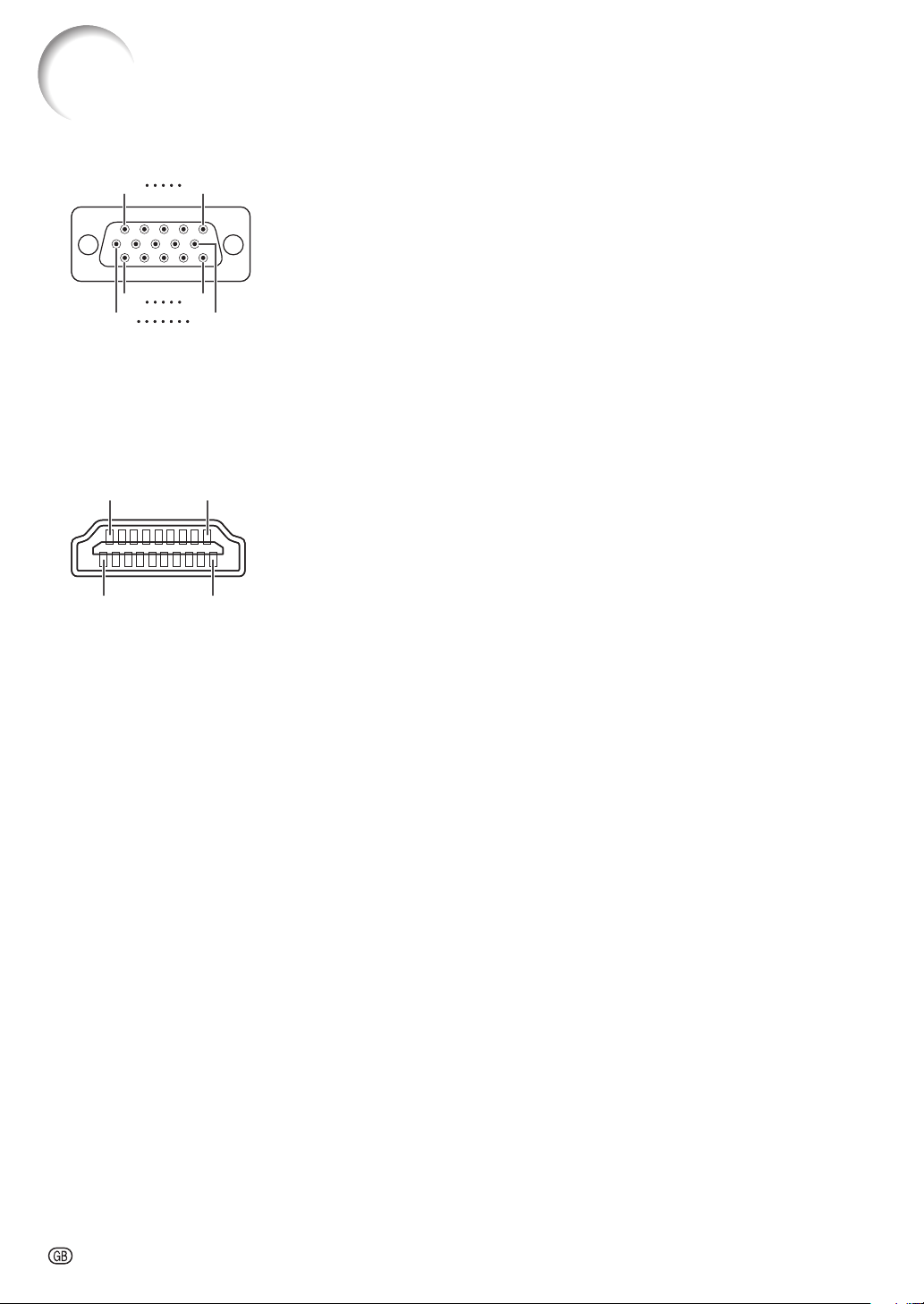
COMPUTER/COMPONENT input and COMPUTER/COMPONENT output Terminals: mini
D-sub 15 pin female connector
11
11
1
1
6
6
HDMI Terminal
15
15
5
5
10
10
218
218
119
119
COMPUTER Input/Output COMPUTER Input/Output
Pin No. Signal Pin No. Signal
1.
Video input (red)
2.
Video input (green/sync on green)
3.
Video input (blue)
4.
Not connected
5.
Not connected
6.
Earth (red)
7.
Earth (green/sync on green)
8.
Earth (blue)
9.
Not connected
10.
GND
11.
Not connected
12.
Bi-directional data
13.
Horizontal sync signal: TTL level
14.
Vertical sync signal: TTL level
15.
Data clock
Pin No. Name Pin No. Name Pin No. Name
1.
T.M.D.S data 2+
2.
T.M.D.S data 2 shield
3.
T.M.D.S data 2–
4.
T.M.D.S data 1+
5.
T.M.D.S data 1 shield
6.
T.M.D.S data 1–
7.
T.M.D.S data 0+
8.
T.M.D.S data 0 shield
9.
T.M.D.S data 0–
10.
T.M .D .S cl ock+
11.
T.M.D.S clock shield
12.
T.M .D .S cl ock–
13.
CEC
1.
2.
3.
4.
5.
6.
7.
8.
9.
10.
11.
12.
13.
14.
15.
PR (CR)
Y
PB (CB)
Not connected
Not connected
Earth (PR)
Earth (Y)
Earth (PB)
Not connected
Not connected
Not connected
Not connected
Not connected
Not connected
Not connected
14.
Reserved
15.
SCL
16.
SDA
17.
DDC/CEC ground
18.
+5V power
19.
Hot plug detection
-2
Page 3
Connecting Pin Assignments
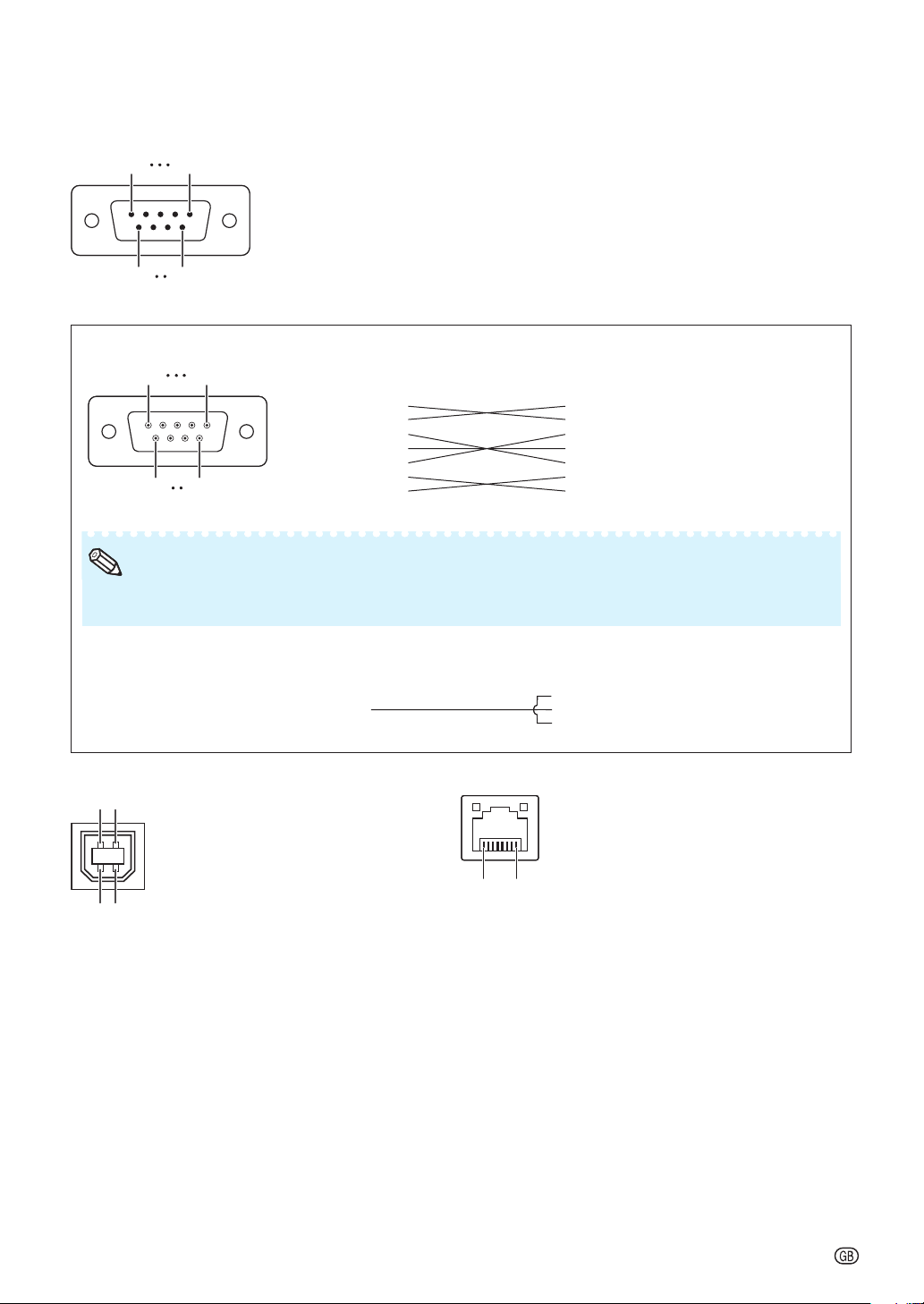
RS-232C Terminal: D-sub 9 pin male connector
15
15
69
69
RS-232C Cable recommended connection: D-sub 9 pin female connector
51
51
96
96
Note
Note
Depending on the controlling device used, it may be necessary to connect Pin 4 and Pin 6 on the
•
Depending on the controlling device used, it may be necessary to connect Pin 4 and Pin 6 on the
•
controlling device (e.g. computer).
controlling device (e.g. computer).
Pin No. Sign al Name I/O Reference
1.
2.
3.
4.
5.
6.
7.
8.
9.
Pin No. Signal Pin No. Signal
1.
2.
3.
4.
5.
6.
7.
8.
9.
RD
SD
SG
RS
CS
CD
RD
SD
ER
SG
DR
RS
CS
CI
Receive Data
Send Data
Signal Ground
Request to Send
Clear to Send
Input
Output
Not connected
Connected to internal circuit
Connected to internal circuit
Not connected
Connected to internal circuit
Not connected
Connected to CS in internal circuit
Connected to RS in internal circuit
Not connected
1.
2.
3.
4.
5.
6.
7.
8.
9.
CD
RD
SD
ER
SG
DR
RS
CS
CI
Projector
Pin No.
4
5
6
Computer
Pin No.
4
5
6
USB Terminal: Type B USB connector LAN Terminal: LAN (RJ-45)
431243
12
Pin No. Signal Name Pin No. Signal Pin No. Signal
1.
VCC
USB–
USB+
SG
USB power
USB data–
USB data+
Signal Ground
...18...
8
1
2.
3.
4.
1.
TX+
2.
TX–
3.
RX+
4.
5.
6.
RX–
7.
8.
-3
Page 4
RS-232C Specifi cations and Commands
Computer control
A computer can be used to control the projector by connecting an RS-232C serial control cable (cross
type, commercially available) to the projector. (See page 24 of the projector's operation manual for
connection.)
Communication conditions
Set the serial port settings of the computer to match that of the table.
Signal format: Conforms to RS-232C standard. Parity bit: None
Baud rate*: 9,600 bps / 38,400 bps / 115,200 bps Stop bit: 1 bit
Data length: 8 bits Flow control: None
*Set the projector's baud rate to the same rate as used by the computer.
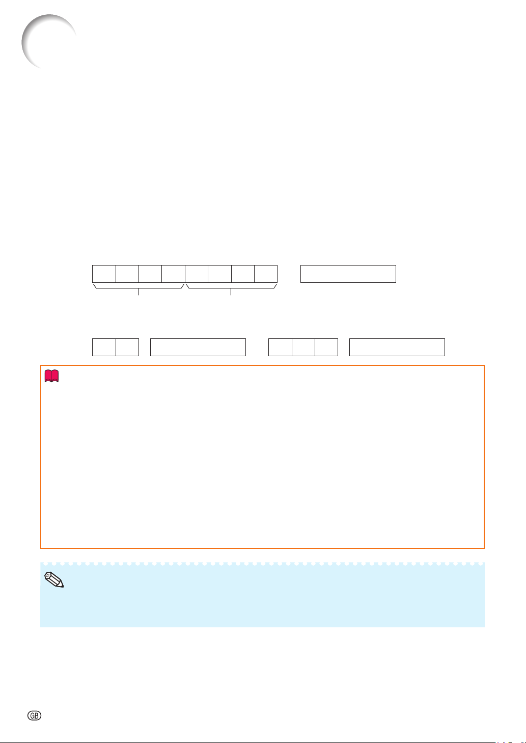
Basic format
Commands from the computer are sent in the following order: command, parameter, and return code.
After the projector processes the command from the computer, it sends a response code to the
computer.
Command format
C1 C2 C3 C 4 P1 P2 P3 P4 Return code (0DH)
Command 4-digit Parameter 4-digit
Response code format
Normal response
OK Return code (0DH) E R R Return code (0DH)
Problem response (communication error or incorrect command)
Info
•
When controlling the projector using RS-232C commands from a computer, wait for at least 30 seconds
after the power has been turned on, and then transmit the commands.
•
After sending an input selection or picture adjustment command and then receiving an “OK” response
code, the projector may take some time to process the command. If a second command is sent while the
projector is still processing the fi rst command, you may receive an “ERR” response code. If this happens,
try resending the second command.
•
When more than one code is being sent, send each command only after the response code for the
previous command from the projector is verifi ed.
•
“POWR????”, “TABN _ _ _ 1”, “TLPS _ _ _ 1”, “TPOW _ _ _ 1”, “TLPN _ _ _ 1”, “TLTT _ _ _ 1”,
“TLTM _ _ _ 1”, “TLTL _ _ _ 1”, “TNAM _ _ _ 1”, “MNRD _ _ _ 1”, “PJN0 _ _ _ 1”
− When the projector receives the special commands shown above:
* The on-screen display will not disappear.
* The “Auto Power Off” timer will not be reset.
− The special commands are available for applications that require continuous polling.
Note
If an underbar (_) appears in the parameter column, enter a space.
•
If an asterisk (*) appears in the parameter column, enter a value in the range indicated in brackets under
•
Control Contents.
PJLinkTM Compliant:
This product conforms with the PJLink standard Class 1 and all Class 1 commands are implemented.
This product confi rms with the PJLink standard specifi cation version 1.00.
For additional information, visit “http://pjlink.jbmia.or.jp/english/”.
-4
Page 5
RS-232C Specifi cations and Commands
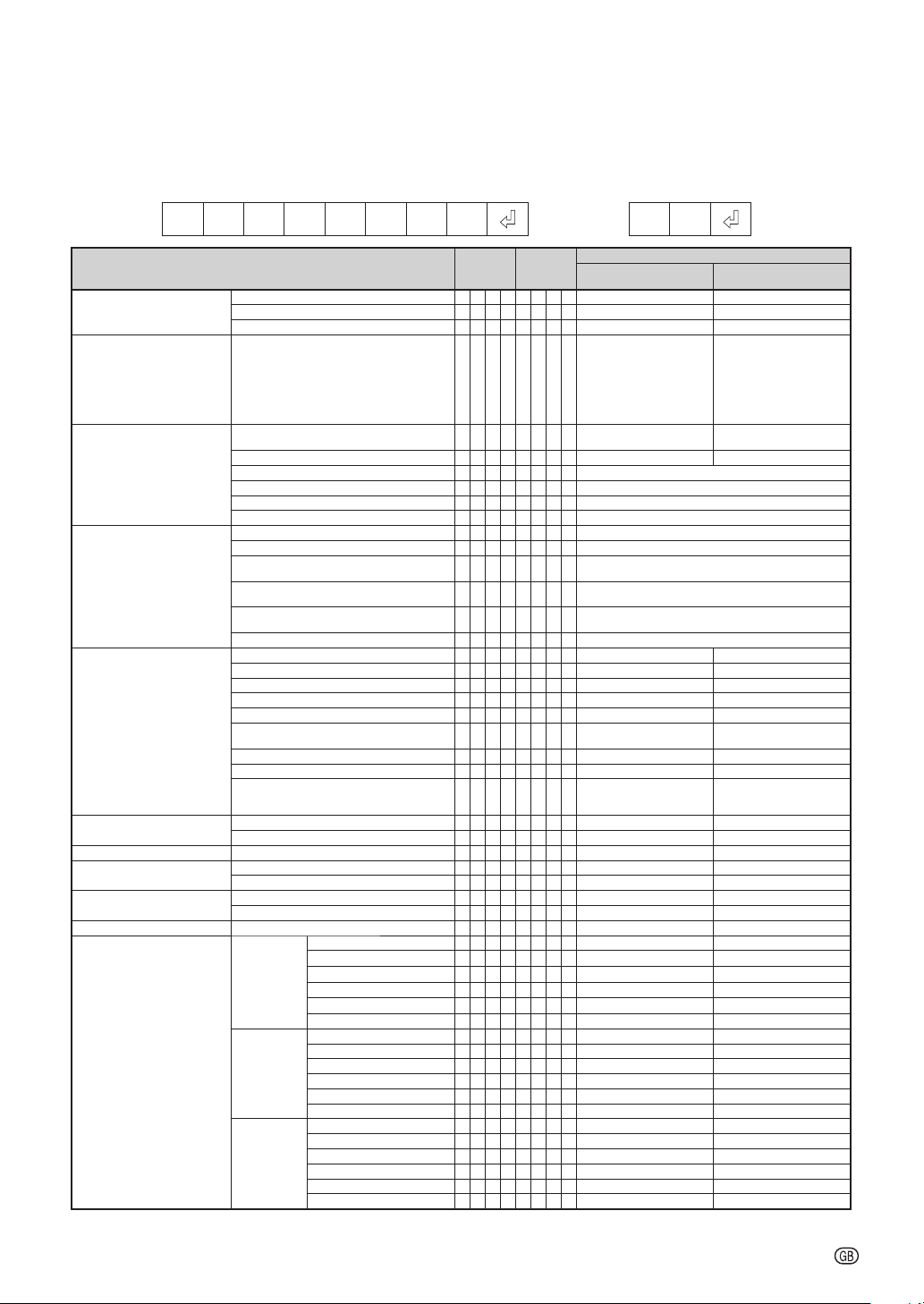
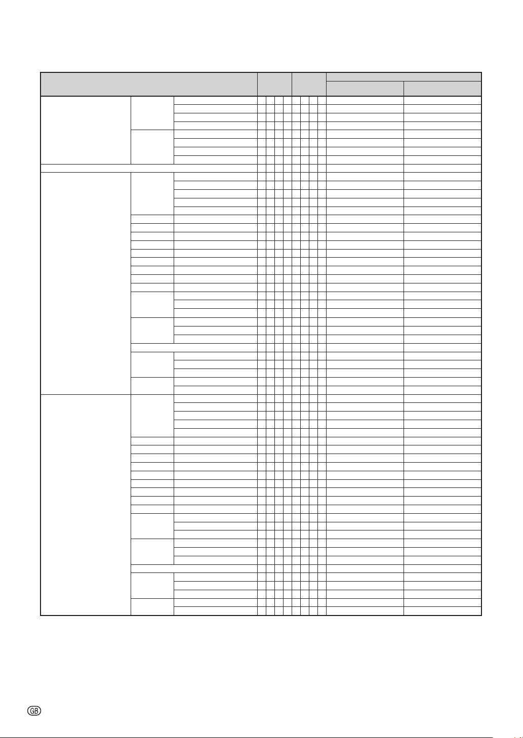
Commands
Example: When turning on the projector, make the following setting.
Compuer Projector
POWR___1
CONTROL CONTENTS COMMAND PARAMETER
Power On P O W R
Projec tor Conditi on T A B N
Lamp Status T L P S
Name Model Name Check T N A M
Input Change Computer1 I R G B
Volum e Volum e(0 – 60 ) V O L A
Keystone -80 – +80 K E Y S * * * * OK or ER R ERR
AV Mut e On I M B K
Freeze On F R E Z
Auto Sync Start A D J S
Resize Computer1 Normal R A S R
Off P O W R
Status POWR????1 0
Power Status T P O W
Quantity T L P N
Usage Time(Hour) T L T T
Usage Time(Minute) T L T M
Life(Percentage) TLTL
Model Name Check M N R D
Projec tor Name Set ting 1
(Firs t 4 character s) *1
Projec tor Name Set ting 2
(Middl e 4 characte rs) *1
Projec tor Name Set ting 3
(Last 4 c haracter s) *1
Projec tor Name Che ck P J N 0
Computer2 I R G B
HDMI I R G B
S-Video I V E D
Video I V E D
Input RGB Check I R G B ? ? ? ? 1: Computer1, 2: Computer2,
Input V ideo Check I V E D ? ? ? ? 1: S-Vide o, 2: Video or ER R ERR
Input Mo de Check I M O D ? ? ? ? 1: RGB, 2: Vide o ERR
Input Check I C H K ? ? ? ? 1: Computer1, 2: Computer2,
Volume up/d own(-10 – +10) V O U D_***OK or ERR ERR
Off I M B K
Off F R E Z
Stretch R A S R
Dot By Dot R A S R
Full R A S R
Area Zoom R A S R
Computer2 Normal R B S R
HDMI Normal R C S R
V-Stretch R A S R
Stretch R B S R
Dot By Dot R B S R
Full R B S R
Area Zoom R B S R
V-Stretch R B S R
Stretch R C S R
Dot By Dot R C S R
Full R C S R
Area Zoom R C S R
V-Stretch R C S R
PJN1****OK or ERR
PJN2****OK or ERR
PJN3****OK or ERR
→
←
___
1 OK or E RR OK
___
0 OK OK or ERR
___
10: Normal
1: Tem p Hig h
8: Lamp Life 5% or less
16: Lamp Bu rn-out
32: Lamp I gnition Fail ure
___
1 0: Of f, 1: On, 2: Retr y
___
___
___
___
___
___
___
___
___
___
___
___
___
__
___
___
___
___
___
___
___
___
___
__
__
___
___
___
___
__
__
___
___
___
___
__
__
3: Waiting , 4: Lamp Error
1 1: On, 2: Coo ling 0: Stand by
11
1 0 – 9999(Integer)
1 0, 15, 30, 4 5
1 0% – 100%(I nteger)
1PGD40W3D
1PG-D40W3D
1Projector Name
1 OK or E RR ER R
2 OK or E RR ER R
3 OK or E RR ER R
1 OK or E RR ER R
2 OK or E RR ER R
3: HDMI, ER R
3: HDMI, 4: S-V ideo,
5: Video
**OK or ERR ERR
1 OK or E RR ER R
0 OK or E RR ER R
1 OK or E RR ER R
0 OK or E RR ER R
1 OK or E RR ER R
1 OK or E RR ER R
2 OK or E RR ER R
3 OK or E RR ER R
5 OK or E RR ER R
10OK or ERR ERR
11OK or ERR ERR
1 OK or E RR ER R
2 OK or E RR ER R
3 OK or E RR ER R
5 OK or E RR ER R
10OK or ERR ERR
11OK or ERR ERR
1 OK or E RR ER R
2 OK or E RR ER R
3 OK or E RR ER R
5 OK or E RR ER R
10OK or ERR ERR
11OK or ERR ERR
OK
Power ON
RETURN
Standby mode
(or 30- second start up time)
0: Normal
1: Tem p Hig h
2: Fan Erro r
4: Cover Open
8: Lamp L ife 5% or less
16: L amp Bu rn-o ut
32: Lamp I gnition Failu re
Temp Abnormally High
64:
0: Off, 4: L amp Error
ERR
ERR
-5
Page 6
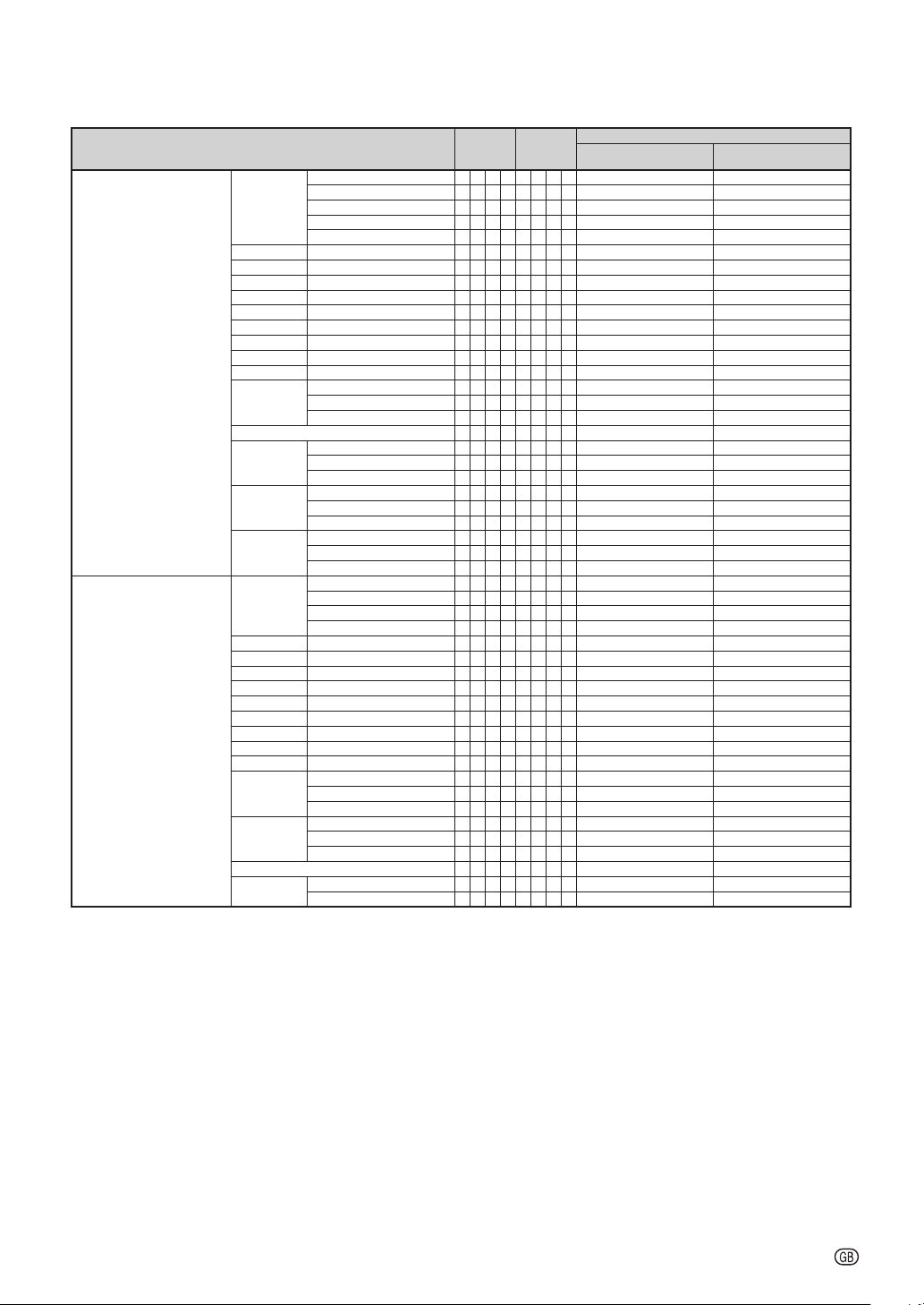
RS-232C Specifi cations and Commands
CONTROL CONTENTS COMMAND PARAMETER
Resize S-Video Normal R A S V
Video Normal R B S V
ALL Res et ALRE
Computer1 INPUT Picture Mode Standard R A P S
Contra st -30 – +30 R A P I_* * * OK o r ERR E RR
Brigh t -30 – +30 R A B R_* * * OK o r ERR E RR
Red -30 – +30 R A R D_* * * OK o r ERR E RR
Blue -30 – +30 R A B E_* * * OK o r ERR E RR
Color -30 – +3 0 R A C O_* * * OK o r ERR E RR
Tint -30 – +30 R A T I_* * * OK o r ERR E RR
Sharp -30 – +30 R A S H_* * * OK o r ERR E RR
CLR Temp -1 – +1 R A C T
BrilliantColor™
Progressive 2D Progressive R A I P
DNR Off R A N R
Pictur e Reset R A R E
Signal Type Auto I A S I
Audio Input Audio 1 R A A I
Computer2 INPUT Picture Mode Standard R B P S
Contra st -30 – +30 R B P I_* * * OK o r ERR E RR
Bright -30 – +30 RBBR_* * * OK o r ERR E RR
Red -30 – +30 R B R D_* * * OK o r ERR E RR
Blue -30 – +30 R B B E_* * * OK o r ERR E RR
Color -30 – +3 0 R B C O_* * * OK o r ERR E RR
Tint -30 – +30 R B T I_* * * OK o r ERR E RR
Sharp -30 – +30 R B S H_* * * OK o r ERR E RR
CLR Temp -1 – +1 R B C T
BrilliantColor™
Progressive 2D Progressive R B I P
DNR Off R B N R
Picture Reset RBRE
Signal Type Auto I B S I
Audio Input Audio 1 R B A I
Stretch R A S V
Area Zoom R A S V
V-Stretch R A S V
Stretch R B S V
Area Zoom R B S V
V-Stretch R B S V
Presentation RAPS__11OK or ERR ERR
Movie RAPS__12OK or ERR ERR
Game RAPS__13OK or ERR ERR
sRGB RAPS__14OK or ERR ERR
0 – +2 R A W E
3D Progressive R A I P
Film Mode
Level 1 R A N R
Level 2 R A N R
RGB I A S I
Component I A S I
Audio 2 R A A I
Presentation R B P S
Movie R B P S
Game R B P S
sRGB R B P S
0 – +2 R B W E
3D Progressive R B I P
Film Mode R B I P
Level 1 R B N R
Level 2 R B N R
RGB I B S I
Component I B S I
Audio 2 R B A I
RA I P
Power ON
___
1 OK or E RR ER R
___
2 OK or E RR ER R
__
10OK or ERR ERR
__
11OK or ERR ERR
___
1 OK or E RR ER R
___
2 OK or E RR ER R
__
10OK or ERR ERR
__
11OK or ERR ERR
___
1 OK or E RR ER R
__
10OK or ERR ERR
__
**OK or ERR ERR
___
* OK or ERR ERR
___
0 OK or E RR ER R
___
1 OK or E RR ER R
___
___
___
___
___
___
___
___
___
___
__
__
__
__
__
__
___
___
___
___
___
___
___
___
___
___
___
___
___
OK or ERR ERR
2
0 OK or E RR ER R
1 OK or E RR ER R
2 OK or E RR ER R
1 OK or E RR ER R
0 OK or E RR ER R
1 OK or E RR ER R
2 OK or E RR ER R
1 OK or E RR ER R
2 OK or E RR ER R
10OK or ERR ERR
11OK or ERR ERR
12OK or ERR ERR
13OK or ERR ERR
14OK or ERR ERR
**OK or ERR ERR
* OK or ERR ERR
0 OK or E RR ER R
1 OK or E RR ER R
2 OK or E RR ER R
0 OK or E RR ER R
1 OK or E RR ER R
2 OK or E RR ER R
1 OK or E RR ER R
0 OK or E RR ER R
1 OK or E RR ER R
2 OK or E RR ER R
1 OK or E RR ER R
2 OK or E RR ER R
RETURN
(or 30- second start up time)
Standby mode
-6
Page 7
RS-232C Specifi cations and Commands
CONTROL CONTENTS COMMAND PARAMETER
HDMI INPUT Picture Mode Standard R C P S
Contra st -30 – +30 R C P I_***OK or ERR ERR
Brigh t -30 – +30 R C B R_***OK or ERR ERR
Red -30 – +30 R C R D_***OK or ERR ERR
Blue -30 – +30 R C B E_***OK or ERR ERR
Color -30 – +3 0 R C C O_***OK or ERR ERR
Tint -30 – +30 R C T I_***OK or ERR ERR
Sharp -30 – +30 R C S H_***OK or ERR ERR
CLR Temp -1 – +1 R C C T
BrilliantColor™
DNR Off R C N R
Pictur e Reset R C R E
Signal Type Auto I C S I
Audio Input Audio 1 R C A I
Dynamic
Range
S-Video INPUT Picture Mode Standard V A P S
Contra st -30 – +30 V A P I_***OK or ERR ERR
Brigh t -30 – +30 V A B R_***OK or ERR ERR
Red -30 – +30 V A R D_***OK or ERR ERR
Blue -30 – +30 V A B E_***OK or ERR ERR
Color -30 – +3 0 V A C O_***OK or ERR ERR
Tint -30 – +30 V A T I_***OK or ERR ERR
Sharp -30 – +30 V A S H_***OK or ERR ERR
CLR Temp -1 – +1 V A C T
BrilliantColor™
Progressive 2D Progressive V A I P
DNR Off V A N R
Pictur e Reset V A R E
Audio Input Audio 1 V A A I
Presentation R C P S
Movie R C P S
Game R C P S
sRGB R C P S
0 – +2 R C W E
Level 1 R C N R
Level 2 R C N R
RGB I C S I
Component I C S I
Audio 2 R C A I
HDMI R C A I
Auto H M C D
Standard H M C D
Enhanced H M C D
Presentation VAPS__11OK or ERR ERR
Movie VAPS__12OK or ERR ERR
Game V APS__13OK or ERR ERR
0 – +2 V A W E
3D Progressive V A I P
Film Mode V A I P
Level 1 V A N R
Level 2 V A N R
Audio 2 V A A I
Power ON
__
10OK or ERR ERR
__
11OK or ERR ERR
__
12OK or ERR ERR
__
13OK or ERR ERR
__
14OK or ERR ERR
__
**OK or ERR ERR
___
* OK or ERR ERR
___
0 OK or E RR ER R
___
1 OK or E RR ER R
___
2 OK or E RR ER R
___
1 OK or E RR ER R
___
0 OK or E RR ER R
___
1 OK or E RR ER R
___
2 OK or E RR ER R
___
1 OK or E RR ER R
___
2 OK or E RR ER R
___
3 OK or E RR ER R
___
0 OK or E RR ER R
___
1 OK or E RR ER R
___
2 OK or E RR ER R
__
10OK or ERR ERR
__
**OK or ERR ERR
___
* OK or ERR ERR
___
0 OK or E RR ER R
___
1 OK or E RR ER R
___
2 OK or E RR ER R
___
0 OK or E RR ER R
___
1 OK or E RR ER R
___
2 OK or E RR ER R
___
1 OK or E RR ER R
___
1 OK or E RR ER R
___
2 OK or E RR ER R
RETURN
(or 30- second start up time)
Standby mode
-7
Page 8
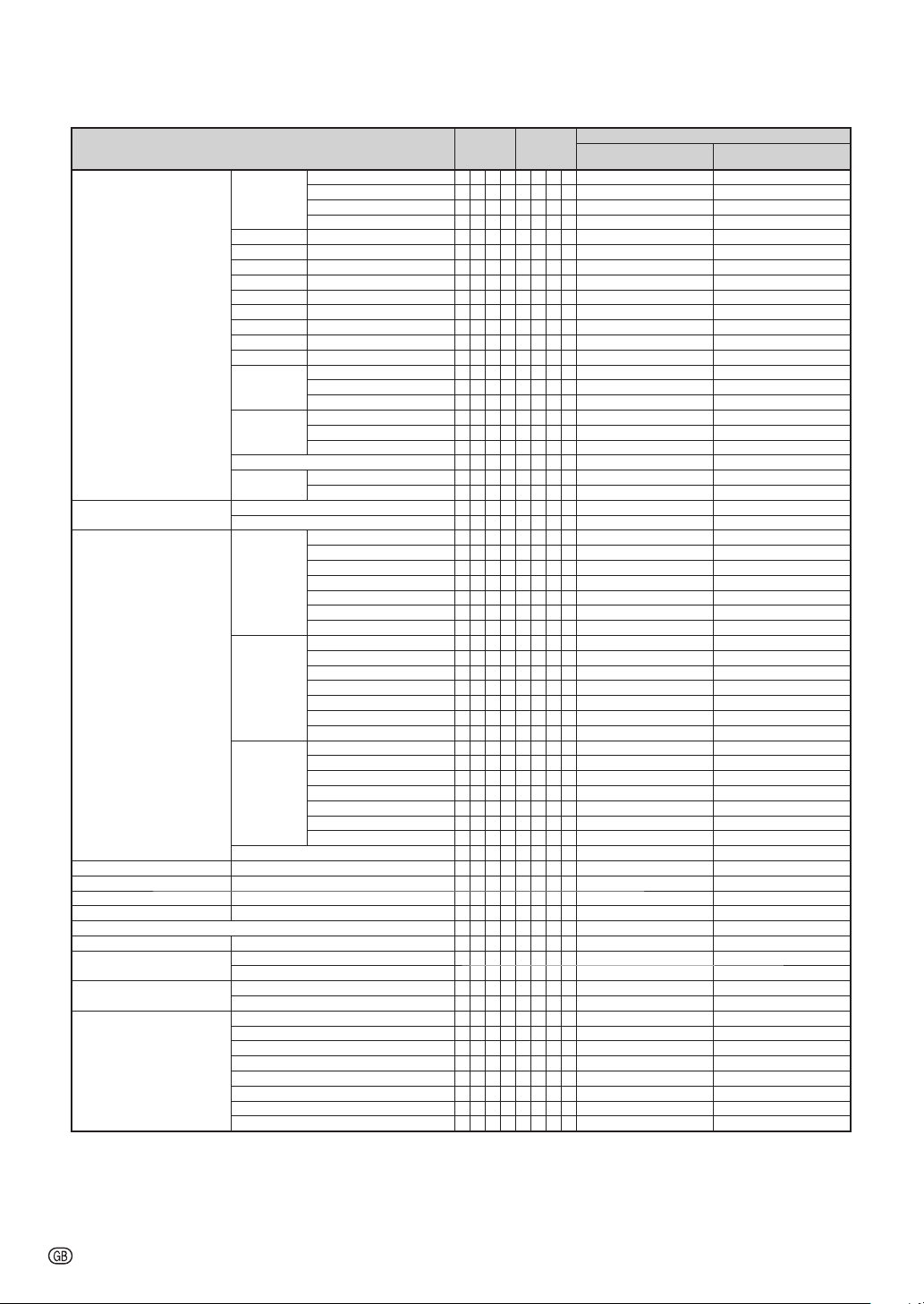
RS-232C Specifi cations and Commands
CONTROL CONTENTS COMMAND PARAMETER
Video INPUT Picture Mode Standard V B P S
Contra st -30 – +30 V B P I_* * * OK o r ERR E RR
Brigh t -30 – +30 V B B R_* * * OK o r ERR E RR
Red -30 – +30 V B R D_* * * OK o r ERR E RR
Blue -30 – +30 V B B E_* * * OK o r ERR E RR
Color -30 – +3 0 V B C O_* * * OK o r ERR E RR
Tint -30 – +30 V B T I_* * * OK o r ERR E RR
Sharp -30 – +30 V B S H_* * * OK o r ERR E RR
CLR Temp -1 – +1 V B C T
BrilliantColor™
Progressive 2D Progressive V B I P
DNR Off V B N R
Pictur e Reset V B R E
Audio Input Audio 1 V B A I
C.M.S. Sett ing On C M C S
Off C M C S
C.M.S. Hue Red C M H R_* * * OK o r ERR E RR
Saturation Red C M S R_* * * OK o r ERR E RR
Value Red C M V R_* * * OK o r ERR E RR
C.M.S. Al l Reset C M R E
Clock -150 – +150 I N C L * * * * OK or ERR ERR
Phase - 30 – +30 I N P H_* * * OK o r ERR E RR
H-position -150 – +150 IAHP****OK or ERR ERR
V-posi tion -60 – + 60 I A V P_* * * OK o r ERR E RR
Fine Sync Adjustment Reset I A R E
Image S hift - 40 – +40 L N D S_***OK or ERR ERR
Overscan On O V S N
Off O V S N
OSD Dis play On I M D I
Off I M D I
Video System Auto M E S Y
PAL M E S Y
SECAM M E S Y
NTSC4.43 M E S Y
NTSC3.58 M E S Y
PAL-M M E S Y
PAL-N M E S Y
PAL-6 0 M E S Y
Presentation V B P S
Movie V B P S
Game V B P S
0 – +2 V B W E
3D Progressive V B I P
Film Mode V B I P
Level 1 V B N R
Level 2 V B N R
Audio 2 V B A I
Yel low C M H Y_* * * OK o r ERR E RR
Green C M H G_* * * OK o r ERR E RR
Cyan C M H C_* * * OK o r ERR E RR
Blue C M H B_* * * OK o r ERR E RR
Magenta C M H M_* * * OK o r ERR E RR
Reset C M R E
Yel low C M S Y_* * * OK o r ERR E RR
Green C M S G_* * * OK o r ERR E RR
Cyan C M S C_* * * OK o r ERR E RR
Blue C M S B_* * * OK o r ERR E RR
Magenta C M S M_* * * OK o r ERR E RR
Reset C M R E
Yel low C M V Y_* * * OK o r ERR E RR
Green C M V G_* * * OK o r ERR E RR
Cyan C M V C_* * * OK o r ERR E RR
Blue C M V B_* * * OK o r ERR E RR
Magenta C M V M_* * * OK o r ERR E RR
Reset C M R E
__
10OK or ERR ERR
__
11OK or ERR ERR
__
12OK or ERR ERR
__
13OK or ERR ERR
__
**OK or ERR ERR
___
* OK or ERR ERR
___
0 OK or E RR ER R
___
1 OK or E RR ER R
___
2 OK or E RR ER R
___
0 OK or E RR ER R
___
1 OK or E RR ER R
___
2 OK or E RR ER R
___
1 OK or E RR ER R
___
1 OK or E RR ER R
___
2 OK or E RR ER R
__
11OK or ERR ERR
__
00OK or ERR ERR
___
2 OK or E RR ER R
___
3 OK or E RR ER R
___
4 OK or E RR ER R
___
1 OK or E RR ER R
___
1 OK or E RR ER R
___
1 OK or E RR ER R
___
0 OK or E RR ER R
___
1 OK or E RR ER R
___
0 OK or E RR ER R
___
1 OK or E RR ER R
___
2 OK or E RR ER R
___
3 OK or E RR ER R
___
4 OK or E RR ER R
___
5 OK or E RR ER R
___
6 OK or E RR ER R
___
7 OK or E RR ER R
___
8 OK or E RR ER R
Power ON
RETURN
(or 30- second start up time)
Standby mode
-8
Page 9
RS-232C Specifi cations and Commands
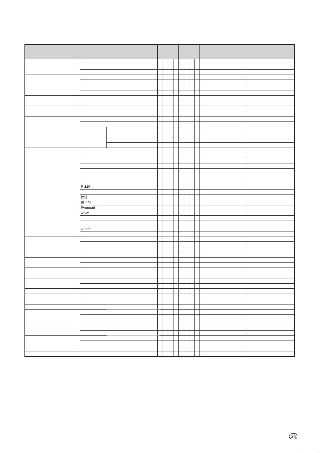
CONTROL CONTENTS COMMAND PARAMETER
Background Logo I M B G
Eco+Quiet On T H M D
Auto Sync On A A D J
Auto Power O ff On A P O W
Auto Restart On A R E S
STANDBY Mode Standard M O U T
PRJ Mode Reve rse On I M R E
Language English M E L A
System Sound On S S N D
Audio Out FAO A O U T
Internal Speaker On ASPK
RGB Freq uency Check Hori zontal T F R Q
Fan Mode Normal H L M D
Balan ce - 30 − +30 A A B L_***OK or ERR ERR
Treble - 30 − +30 A A T E_***OK or ERR ERR
Bass -30 − +30 A A B A_***OK or ERR ERR
Audio Ad justment Re set A A R E
®
TM
DLP
Link
DLP® LinkTM Invert 3 D I V _ _ _ 1 OK or ERR ERR
Video S etup 0 I RE V I S U _ _ _ 0 OK or E RR ER R
Closed Caption
(For Ame ricas onl y)
Lamp Timer Reset *3 LPRE0001ERR OK or ERR
Blue I M B G
None I M B G
Off T H M D
Off A A D J
Off A P O W
Off A R E S
Eco M O U T
Off I M R E
Invert On I M I N
Off I M I N
Deutsch M E L A
Español M E L A
Nederlands M E L A
Français M E L A
Italiano M E L A
Svenska M E L A
ME LA
Português M E L A
ME LA__10OK or ERR ERR
ME LA__11OK or ERR ERR
ME LA__12OK or ERR ERR
ME LA__13OK or ERR ERR
polski M E L A
Türkçe M E L A
ME LA__16OK or ERR ERR
Magyar M E L A
Off S S N D
VAO A O U T
Off ASPK
Vert ical T F R Q
High H L M D
Off 3DEN___0OK or ERR ERR
On 3DEN___1OK or ERR ERR
7.5 IRE V ISU___1OK or ERR ERR
Off CLCA___0OK or ERR ERR
CC1 CLCA___1OK or ERR ERR
CC2 CLCA___2OK or ERR ERR
___
1 OK or E RR ER R
___
3 OK or E RR ER R
___
4 OK or E RR ER R
___
1 OK or E RR ER R
___
0 OK or E RR ER R
___
1 OK or E RR ER R
___
0 OK or E RR ER R
___
1 OK or E RR ER R
___
0 OK or E RR ER R
___
1 OK or E RR ER R
___
0 OK or E RR ER R
___
1 OK or E RR ER R
___
0 OK or E RR ER R
___
1 OK or E RR ER R
___
0 OK or E RR ER R
___
1 OK or E RR ER R
___
0 OK or E RR ER R
___
1 OK or E RR ER R
___
2 OK or E RR ER R
___
3 OK or E RR ER R
___
4 OK or E RR ER R
___
5 OK or E RR ER R
___
6 OK or E RR ER R
___
7 OK or E RR ER R
___
8 OK or E RR ER R
___
9 OK or E RR ER R
__
14OK or ERR ERR
__
15OK or ERR ERR
__
17OK or ERR ERR
___
1 OK or E RR ER R
___
0 OK or E RR ER R
___
1 OK or E RR ER R
___
2 OK or E RR ER R
___
1 OK or E RR ER R
___
0 OK or E RR ER R
___
1 kHz(***.* or ERR) ERR
___
2 Hz(***.* or ERR) ERR
___
0 OK or E RR ER R
___
1 OK or E RR ER R
___
1 OK or E RR ER R
Power ON
RETURN
(or 30- second start up time)
Standby mode
*1 For setting the projector name, send the commands in the order of PJN1, PJN2 and PJN3.
*2 This command should be sent only after the “IRGB _ _ _ 2” command is sent and an “OK” response code is
received.
*3 The Lamp Timer Reset command is available only in standby mode.
-9
Page 10
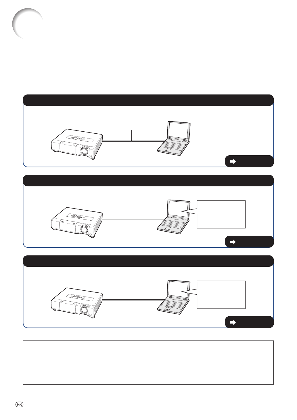
Setting up the Projector Network Environment
This section describes the basic procedure for using the projector via the network.
If the network is already constructed, the projector's network settings may need to be
changed. Please consult your network administrator for assistance with these settings.
You can make network settings both on the projector and on the computer. The following
procedure is for making settings on the computer.
Network settings on the computer
1. Connecting the projector to a computer
Connect a LAN cable (Category 5, cross-over type) between the computer and projector.
LAN cable
(commercially available)
Page 11
2. Setting an IP address for the computer
Adjust the IP settings of the computer to enable one-to-one communications with the projector.
Temporarily change
the computer's IP
address.
Pages 12, 13
3. Setting up a network connection for the projector
Adjust the projector network settings to conform to your network.
Use Internet Explorer
(version 5.0 or later)
to make various
projector settings.
Pages 14, 15
•
Microsoft®, Windows® and Windows Vista® are registered trademarks of Microsoft Corporation in the
United States and/or other countries.
•
PJLink is a registered trademark or an application trademark in Japan, the United States, Canada, E.U.,
China and/or other countries/regions.
All other company or product names are trademarks or registered trademarks of their respective
•
companies.
-10
Page 11
3
4
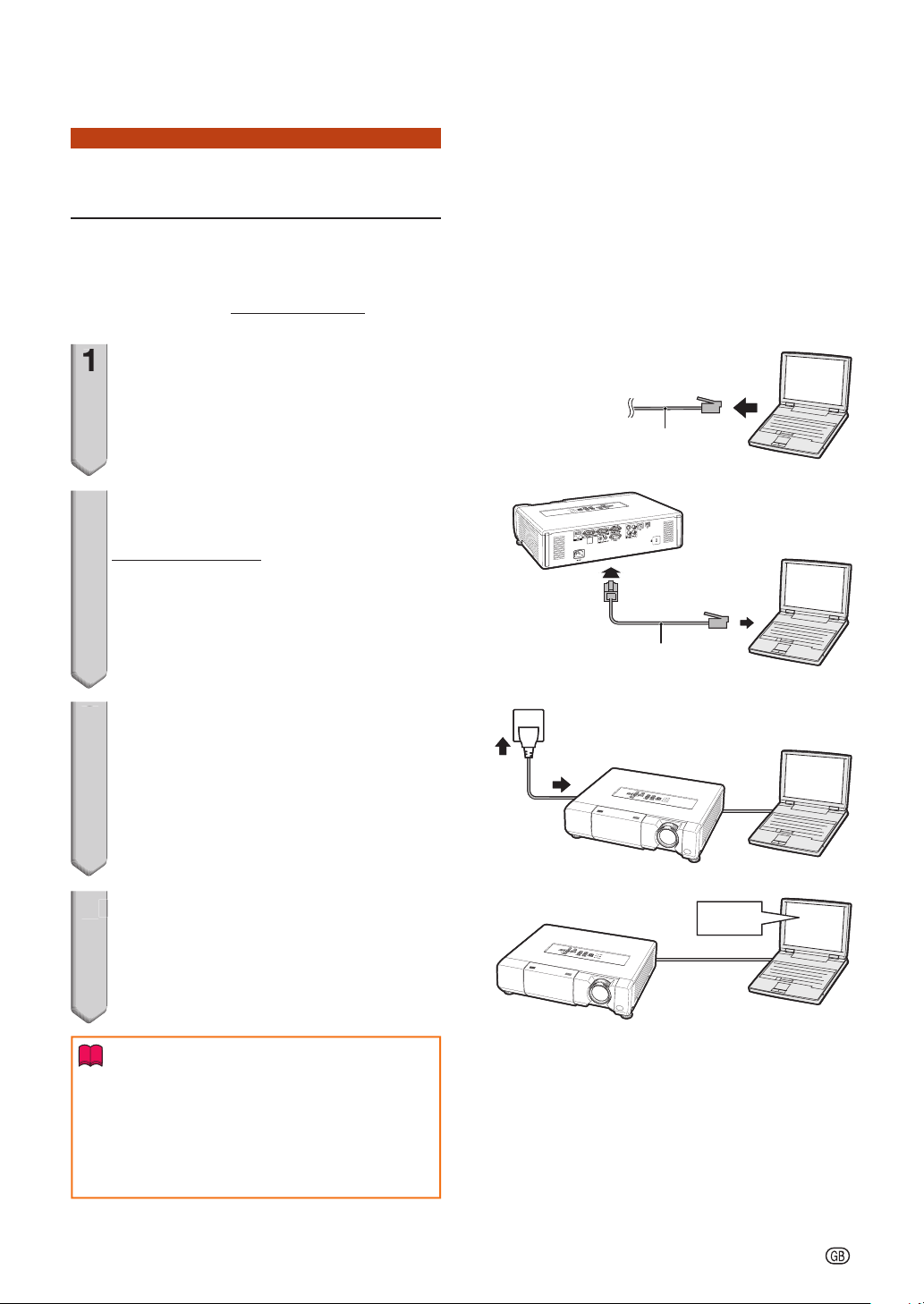
Setting up the Projector Network Environment
1. Connecting the Projector to a Computer
Establishing a one-to-one connection from
the projector to a computer. Using a
commercially available LAN cable (UTP
cable, Category 5, cross-over type) you can
confi gure the projector via the computer.
Disconnect the computer's LAN
1
cable from the existing network.
Connect a commercially available
2
LAN cable (UTP cable, Category 5,
cross-over type) to the projector's
LAN terminal and connect the
other end of the cable to the
computer's LAN terminal.
A LAN cable being
A LAN cable being
connected to the network
connected to the network
Plug the power cord into the AC
3
socket of the projector.
Turn on the computer.
4
Info
Confi rm that the LINK LED on the rear of the
projector illuminates. If the LINK LED does not
illuminate, check the following:
The LAN cable is properly connected.
•
The power switches of both the projector and
•
the computer are on.
LAN cable
LAN cable
(cross-over type, commercially available)
(cross-over type, commercially available)
ONON
This completes the connection. Now proceed to “2. Setting an IP Address for the Computer”.
-11
Page 12

3
Setting up the Projector Network Environment
2. Setting an IP Address for the Computer
The following describes how to make
settings in Windows Vista®.
Log on the network using the
1
administrator's account for the
computer.
Click “start”, and click “Control
2
Panel”.
121
Click “View network status and
3
tasks” of “Network and Internet”,
and click “View status” in the new
window.
This manual uses examples to explain the
•
operations in Category View. If you are using
Classic View, double-click “Network and
Sharing Center”.
121
2
Click “Properties”.
4
When the user account control display is
•
displayed, click “Continue”.
-12
2
11
Page 13

5
6
Setting up the Projector Network Environment
Click “Internet Protocol Version 4
5
(TCP/IPv4)”, and click the
“Properties” button.
121
2
Confi rm or change an IP address
6
for the setup computer.
1 Confi rm and note the current IP
address, Subnet mask and Default
gateway.
Make sure to note the current IP address,
Subnet mask and Default gateway as you
will be required to reset them later.
2 Set temporarily as follows:
IP address: 192.168.150.3
Subnet mask: 255.255.255.0
Default gateway: (Do not input any
values.)
Note
•
The factory default settings for the projector are
as follows:
DHCP Client: OFF
IP address: 192.168.150.2
Subnet mask: 255.255.255.0
Default gateway: 0.0.0.0
After setting, click the “OK”
7
button, and then restart the
computer.
After confi rming or setting, proceed to “3. Setting up Network Connection for the Projector”.
-13
Page 14

3
Setting up the Projector Network Environment
3.
Setting up a Network Connection for the Projector
Settings for such items as the projector's
IP address and subnet mask are
compatible with the existing network.
Set each item on the projector as follows.
(See page 50 of the projector's operation
manual for setting.)
DHCP Client: Off
IP Address: 192 .168.150.002
Subnet Mask: 255.255.255.000
Start Internet Explorer (version 5.0
1
or later) on the computer, and
enter “http://192.168.150.2/” in
“Address”, and then press the
“Enter” key.
If a user name and a password
2
have not yet been set, just click
the “OK” button.
If a user name and a password have been
•
set, input the user name and the password,
and click the “OK” button.
If the user name or password is entered
•
incorrectly three times, an error message will
be displayed.
When you are using Internet Explorer 7, other
•
setup screen may be displayed. In this case,
make the proper adjustments for the setup
screen.
When the screen as shown on the
3
right appears, click “TCP/IP”.
-14
Page 15

The TCP/IP setting screen
5
6
4
appears, ready for network
settings for the projector.
Items Setting example / Remarks
New
Password
DHCP
Client
IP
Address
Subnet
Mask
Default
Gateway
DNS
Server
You can set the password to protect
the TCP/IP setting.
Select “ON” or “OFF” to determine
whether to use DHCP Client.
You can set this item when “DHCP
Client” is set to “OFF”.
Factory default setting: 192.168.150.2
Enter an IP address appropriate for
the network.
You can set this item when “DHCP
Client” is set to “OFF”.
Factory default setting:
255.255.255.0
Set the subnet mask to the same as
that of the computer and equipment
on the network.
You can set this item when “DHCP
Client” is set to “OFF”.
Factory default setting: 0.0.0.0
* When not in use, set to “0.0.0.0”.
Factory default setting: 0.0.0.0
* When not in use, set to “0.0.0.0”.
Setting up the Projector Network Environment
Note
•
Confi rm the existing network's segment (IP
address group) to avoid setting an IP address
that duplicates the IP addresses of other
network equipment or computers. If
“192.168.150.2” is not used in the network
having an IP address of “192.168.150.XXX”, you
don't have to change the projector IP address.
For details about each setting, consult your
•
network administrator.
Click the “Apply” button.
5
The set values appear. Confi rm
6
that the values are set properly,
and then click the “Confi rm”
button.
•
Close the browser.
•
This completes the network settings.
•
After setting items, wait for about 15 seconds and then re-access.
•
Change the IP address of the setting computer back to its original address, which you have noted down in
Step 6-1 on page
13, and then connect the computer and the projector to the network.
-15
Page 16

Controlling the Projector via LAN
2
3
After connecting the projector to your network, enter the projector IP address in
“Address” on Internet Explorer (version 5.0 or later) using a computer on the network to
start a setup screen that will enable control of the projector via the network.
Controlling the Projector
Using Internet Explorer
(Version 5.0 or later)
Complete connections to external
equipment before starting the operation.
(See pages 21-25 of the projector's
operation manual.)
Complete the AC cord connection. (See
page 25 of the projector's operation
manual.)
Note
•
When connecting the projector to the LAN, use
a commercially available LAN cable (UTP cable,
Category 5, cross-over type). When
connecting the projector to a hub, use a
straight-through cable.
Start Internet Explorer (version 5.0
1
or later) on the computer.
Enter “http://” followed by the
2
projector IP address set by the
procedure on page
“/” in “Address”, and then press
the “Enter” key.
When “DHCP Client” is set to “OFF” on the
•
projector, IP address is 192.168.150.2. If you
did not change the IP address in “3. Setting
up a Network Connection for the
Projector” (pages
“http://192.168.150.2/”.
A screen for controlling the
3
projector appears, ready for
performing various status
conditions, control, and settings.
15 followed by
14-15), enter
-16
Page 17

Controlling the Projector via LAN
Confi rming the Projector
Status
On this screen, you can confi rm the
projector status. You can confi rm the
following items:
•
If you click the “Refresh” button before the
screen is displayed completely, an error
message (“Server Busy Error”) will be
displayed. Wait for a moment and then operate
again.
For details about each item, refer to the
•
projector's operation manual.
(Status)
MAC Address
•
Power
•
Condition
•
Lamp Timer
•
Lamp Life
•
Input
•
Signal Info
•
Serial Number
•
Note
Controlling the Projector
(Control)
On this screen, you can perform projector
control. You can control the following
items:
Power
•
Input Select
•
Volume
•
AV Mute
•
Note
•
If you click the “Refresh” button before the
screen is displayed completely, an error
message (“Server Busy Error”) will be
displayed. Wait for a moment and then operate
again.
•
You cannot operate this page while the
projector is warming up.
•
While the projector is in standby mode, you can
only control “Power ON”.
•
For details about each item, refer to the
projector's operation manual.
-17
Page 18

Controlling the Projector via LAN
Setting and Adjusting the
Projector
Example: “Picture” screen display for COMPUTER1
On these screens, you can make projector
settings or adjustments. You can set or
adjust the following items:
Picture Mode
•
CLR Temp
•
BrilliantColor
•
Progressive
•
DNR
•
Eco + Quiet Mode
•
Resolution Setting
•
Signal Type
•
Video System
•
Dynamic Range
•
Resize
•
Overscan
•
OSD Display
•
Background
•
Note
•
If you click the “Refresh” button before the
screen is displayed completely, an error
message (“Server Busy Error”) will be
displayed. Wait for a moment and then operate
again.
•
You cannot operate this page while the
projector is warming up.
•
For details about each item, refer to the
projector's operation manual.
(Settings & Adjustments)
Projection Mode
TM
•
DLP® Link
•
DLP® LinkTM Invert
•
Video Setup
•
OSD Language
•
Auto Sync
•
Auto Power Off
•
Auto Restart
•
System Sound
•
Audio Out
•
Internal Speaker
•
Audio Input
•
RS-232C Speed
•
Fan Mode
•
All Reset
•
TM
Setting the Security
(Network – Security)
On this screen, you can make settings
relating to security.
Items Description
User Name Setting of user name for security
Password Setting of password for security
Accept IP
Address
All IP
Addresses
From only
specifi c IP
addresses
Note
•
User Name and Password can be up to 8
characters.
•
You can input the characters below:
a-z, A-Z, 0-9, -, _
protection.
protection.
It is possible to set up to three IP
addresses allowing connection to the
projector.
No limits are set to IP addresses
connecting to the projector.
For security improvement, only an IP
address set by “Address 1-3” can be
connected to the projector.
-18
Page 19

Controlling the Projector via LAN
Making General Settings for
the Network
On this screen, you can make general
settings relating to the network.
Items Description
Projector
Name
Auto Logout
Time
Data Port Setting the TCP port number used
Search Port Setting the port number used when
Setting the projector name.
Setting the time interval in which the
projector will be automatically
disconnected from the network in units
of a minute (from 1 to 65535 minutes).
If the set value is made 0, the Auto
Logout function is disabled.
when exchanging data with the
projector (from 1025 to 65535).
searching for the projector (from 1025
to 65535).
(Network - General)
Setting for Sending E-mail
when an Error Occurs
(Mail – Originator Settings)
On this screen, you can make settings for
sending e-mail to report when the
projector has generated an error.
Items Setting example / Remarks
SMTP Ser ver Setting an SMTP server address for e-
Originator Email Address
Originator
Name
mail transmission.
e.g.1: 192.168.150.253
e.g.2: smtp123.sharp.co.jp
* When using a domain name, make
settings for the DNS server.
Setting the projector's e-mail address.
The e-mail address set here becomes
Originator E-mail Address.
Setting the sender's name. The name
set here appears in the “Originator
Name” column of the body of the
message.
After clicking the “Apply” button, the set
values appear. Confi rm that the values are
set properly, and then click the “Confi rm”
button.
Note
•
After setting items, wait for about 15 seconds
and then re-access.
•
Projector Name can be up to 12 characters.
•
You can input the characters below:
A-Z, 0-9, -, _, (,), space
(When “a-z” are input, they are converted to
“A-Z” automatically.)
Note
•
SMTP Server, Originator E-mail Address and
Originator Name can be up to 64 characters.
•
You can input the characters below:
SMTP Server and Originator E-mail Address:
a-z, A-Z, 0-9, !, #, $, %, &, *, +, -, /, =, ?, ^, {, |, },
~
, _, ', ., @, `
(You can input “@” only one time for “Originator
E-mail Address”.)
Originator Name : a-z, A-Z, 0-9, -, _, (,), space
If the settings of “3. Setting up a Network
•
Connection for the Projector” on pages
and
15 are incorrectly set, e-mail will not be
sent.
14
-19
Page 20

Controlling the Projector via LAN
Setting Error Items and
Destination Addresses to
which E-mail is to be Sent
when an Error Occurs
(Mail – Recipient Settings)
On this screen, you can input e-mail
destinations to which error notifi cation
(error items) e-mails are sent.
Items Description
E-mail
Address
Error Mail
(Lamp, Temp,
Fan,Cover)
Test Send test e-mail. This allows you to
Note
•
E-mail Address can be up to 64 characters.
•
You can input the characters below:
a-z, A-Z, 0-9, !, #, $, %, &, *, +, -, /, =, ?, ^, {, |, },
~
, _, ', ., @, `
(You can input “@” only one time.)
For details about error items, refer to the
•
projector's operation manual.
Set addresses to which error
notifi cation e-mail is sent. You can set
up to fi ve addresses.
Error e-mail is sent on the error items
checked in their check boxes.
confi rm that the settings for e-mail
transmission are properly set.
Setting Error Items and the
URL that are to be
Displayed when an Error
Occurs
Access URL)
On this screen, you can make settings of
the URL and error items that are to be
displayed when the projector has
generated an error.
Items Description
Access URL Set the URL that is to be displayed
Condition
(Always,
Lamp, Temp,
Fan,Cover)
Test The set URL site is test-displayed. This
Example of the display when an error
occurs
(Service & Support –
when an error occurs. You can set up
to fi ve addresses.
The URL is displayed when an error
checked in their check boxes occurs.
allows you to confi rm that the URL site
is properly displayed.
-20
Page 21

Setting up the Projector Using RS-232C or Telnet
3
5
6
Connect the projector to a computer using RS-232C or Telnet, and open the SETUP
MENU on the computer to carry out various settings for the projector.
Input “setup” and press the
7
When Connecting Using RS-232C
“Enter” key.
SETUP MENU will be displayed.
•
Launch general purpose terminal
1
emulator.
Input settings for the RS-232C
2
port of the terminal emulator as
follows.
Baud Rate : 9600 bps*
Data Length : 8 bit
Parity Bit : None
Stop Bit : 1 bit
Flow Control : None
* This is the factory default setting. If the value
of Baud Rate for the projector has been
changed, set Baud Rate here according to
the changed value on the projector.
Input “PJS11234” and press the
3
“Enter” key.
“OK” is displayed. Input
4
“PJS25678” and press the “Enter”
key within 10 seconds.
▼SETUP MENU
-----------------------------SETUP MENU---------------------------[1]IP Address [2]Subnet Mask [3]Default Gateway
[4]User Name [5]Password
[6]RS-232C Baud Rate [7]Projector Name [8]DHCP Client
[A]Advanced Setup [D]Disconnect All
[V]View All Setting [S]Save & Quit [Q]Quit Unchanged
setup>
Note
•
User name and password are not set in the
factory default settings.
•
If the user name or password is entered
incorrectly three times, SETUP MENU will be
quit.
“User Name:” is displayed. Input
5
the user name and press the
“Enter” key.
•
If a user name has not yet been set, just
press the “Enter” key.
“Password:” is displayed. Input
6
the password and press the
“Enter” key.
If a password has not yet been set, just press
•
the “Enter” key.
-21
Page 22

3
5
6
Setting up the Projector Using RS-232C or Telnet
▼SETUP MENU
When Connecting Using Telnet
Click “Start” from the Windows®
1
desktop and select “Run”.
Enter “telnet 192.168.150.2” in the
2
text box that opens up. (If the IP
address of the projector is
192.168.150.2.)
Click the “OK” button.
3
“User Name:” is displayed. Input
4
the user name and press the
“Enter” key.
If a user name has not yet been set, just
•
press the “Enter” key.
-----------------------------SETUP MENU---------------------------[1]IP Address [2]Subnet Mask [3]Default Gateway
[4]User Name [5]Password
[6]RS-232C Baud Rate [7]Projector Name [8]DHCP Client
[A]Advanced Setup [D]Disconnect All
[V]View All Setting [S]Save & Quit [Q]Quit Unchanged
setup>
Note
•
If the IP address has been changed, be sure to
enter the new IP address in step 2.
•
User name and password are not set in the
factory default settings.
•
If the user name or password is entered
incorrectly three times in steps 4 or 5, SETUP
MENU will be quit.
“Password:” is displayed. Input
5
the password and press the
“Enter” key.
If a password has not yet been set, just press
•
the “Enter” key.
Input “setup” and press the
6
“Enter” key.
SETUP MENU will be displayed.
•
-22
Page 23

Setting up the Projector Using RS-232C or Telnet
SETUP MENU (Main Menu)
▼SETUP MENU
-----------------------------SETUP MENU---------------------------[1]IP Address [2]Subnet Mask [3]Default Gateway
[4]User Name [5]Password
[6]RS-232C Baud Rate [7]Projector Name [8]DHCP Client
[A]Advanced Setup [D]Disconnect All
[V]View All Setting [S]Save & Quit [Q]Quit Unchanged
setup>
[1] IP Address
IP address settings. (Page
[2] Subnet Mask
Subnet mask settings. (Page
[3] Default Gateway
Default gateway settings. (Page
[4] User Name (Factory default setting: Not
Required)
Setting of user name for security protection.
(Page
26)
[5] Password (Factory default setting: Not
Required)
Setting of password for security protection.
(Page
27)
[6]
RS-232C Baud Rate (Factory default setting:
9600 bps)
Baud rate settings for the RS-232C terminals.
(Page
27)
[7] Projector Name
It is possible to assign a projector name. (Page 27)
[8] DHCP Client
DHCP Client settings. (Page
[A] Advanced Setup
Enters ADVANCED SETUP MENU. (Page
[D] Disc onnect All
Disconnect all connections. (Page
[V] View All Setting
Displays all setting values. (Page
Can also be used with ADVANCED SETUP
MENU.
[S] Save & Quit
Save set values and quit menu. (Page
[Q] Quit Unchanged
Quit menu without saving setting values. (Page 25)
26)
26)
26)
27)
28)
28)
24)
25)
ADVANCED SETUP MENU
▼ADVANCED SETUP MENU
********************** ADVANCED SETUP MENU ***************************
[1]Auto Logout Time [2]Data Port
[5]Network Ping Test
[6]Accept IP Addr(1) [7]Accept IP Addr(2) [8]Accept IP Addr(3)
[9]Accept All IP Addr [0]Search Port
[!]Restore Default Setting
[Q]Return to Main Menu
advanced>
[1] Auto Logout Time (Factory default setting:
5 minutes)
Setting of time until automatic disconnection of
network connection. (Page
[2] Data Port (Factory default setting: 10002)
Setting the TCP port number used when
exchanging data. (Page
[5] Network Ping Test
It is possible to confi rm that a network
connection between the projector and a
computer etc. is working normally. (Page
[6] Accept IP Addr(1)
[7] Accept IP Addr(2)
[8] Accept IP Addr(3)
[9] Accept All IP Addr (Factory default setting:
Accept All)
For improved security, it is possible to set up
to three IP addresses allowing connection to
the projector.
Set IP addresses can be cancelled using [9]
Accept All IP Addr. (Page
[0] Search Por t (Factor y default setting: 5006)
Setting the port number used when searching
for the projector. (Page
[!] Restore Default Setting
Restores all setting values that can be set
using the menu to the default state. (Page
[Q] Return to Main Menu
Return to the main SETUP MENU. (Page
28)
28)
29)
29)
30)
30)
30)
Note
•
When “DHCP Client” is set to “OFF” on the
projector:
IP address: 192.168.150.2
Subnet mask: 255.255.255.0
Default gateway: 0.0.0.0
-23
Page 24

Setting up the Projector Using RS-232C or Telnet
Enter number or symbol of item to be selected on the SETUP MENU. When setting, input
the details to be set. Setting is carried out one item at a time, and saved at the end.
View Setting Detail List
([V]View All Setting)
▼SETUP MENU
-----------------------------SETUP MENU---------------------------[1]IP Address [2]Subnet Mask [3]Default Gateway
[4]User Name [5]Password
[6]RS-232C Baud Rate [7]Projector Name [8]DHCP Client
[A]Advanced Setup [D]Disconnect All
[V]View All Setting [S]Save & Quit [Q]Quit Unchanged
setup>v
Model Name : XX-XXXX
Projector Name : XX-XXXX
MAC Address : XX:XX:XX:XX:XX:XX
DHCP Client : Disable
IP Address : 192.168.150.2
Subnet Mask : 255.255.255.0
Default Gateway : Not Used
RS-232 Baud Rate : 9600 bps
Password : Not Required
**********(Advanced Status)**********
Data Port : 10002
Accept IP Address : Accept All
Auto Logout Time : 5 minutes
Search Port : 5006
1 Enter “v” and press the “Enter” key.
Display all setting values(*).
1
Set Items
Example: When setting IP Address (change
from 192.168.150.2 to 192.168.150.3)
▼SETUP MENU
-----------------------------SETUP MENU---------------------------[1]IP Address [2]Subnet Mask [3]Default Gateway
[4]User Name [5]Password
[6]RS-232C Baud Rate [7]Projector Name [8]DHCP Client
[A]Advanced Setup [D]Disconnect All
[V]View All Setting [S]Save & Quit [Q]Quit Unchanged
setup>1
IP Address : 192.168.150.2
Please Enter : 192.168.150.3
(change) —> 192.168.150.3
-----------------------------SETUP MENU----------------------------
*
[1]IP Address [2]Subnet Mask [3]Default Gateway
[4]User Name [5]Password
[6]RS-232C Baud Rate [7]Projector Name
[A]Advanced Setup [D]Disconnect All
[V]View All Setting [S]Save & Quit [Q]Quit Unchanged
setup>v
Model Name : XX-XXXX
Projector Name : XX-XXXX
MAC Address : XX:XX:XX:XX:XX:XX
DHCP Client : Disable
IP Address : 192.168.150.3
Subnet Mask : 255.255.255.0
Default Gateway : Not Used
RS-232C Baud Rate : 9600 bps
Password : Not Required
**********(Advanced Status)**********
Data Port : 10002
Accept IP Address : Accept All
Auto Logout Time : 5 minutes
Search Port : 5006
[8]DHCP Client
1
*1
2
*2
3
*3
-24
1 Enter “1” (number of item to be set), and
press the “Enter” key.
Display current IP address (*1).
2 Enter IP address to be set and press the
“Enter” key.
Display IP address after change (*2).
3 Enter “v” and press the “Enter” key to verify
setting detail list.
IP address is being changed (*3).
Note
•
Verifi cation of setting detail list can be omitted.
•
Setting details are not effective until they have
been saved. (Page
•
If an invalid number is entered, an error
25)
message (“Parameter Error!”) will be displayed.
Page 25

Setting up the Projector Using RS-232C or Telnet
Save Settings and Quit
([S]Save & Quit)
Save set values and quit menu.
▼SETUP MENU
----------------------------SETUP MENU--------------------------[1]IP Address [2]Subnet Mask [3]Default Gateway
[4]User Name [5]Password
[6]RS-232C Baud Rate [7]Projector Name [8]DHCP Client
[A]Advanced Setup [D]Disconnect All
[V]View All Setting [S]Save & Quit [Q]Quit Unchanged
setup>s
All Connection will be disconnect.
Continue(y/n)? y
Apply New setting...Done.
1 Enter “s” and press the “Enter” key.
2 Enter “y” and press the “Enter” key.
1
2
Quit without Saving Settings
Quit menu without saving setting values.
▼SETUP MENU
----------------------------SETUP MENU--------------------------[1]IP Address [2]Subnet Mask [3]Default Gateway
[4]User Name [5]Password
[6]RS-232C Baud Rate [7]Projector Name
[A]Advanced Setup [D]Disconnect All
[V]View All Setting [S]Save & Quit [Q]Quit Unchanged
setup>q
Quit Without Saving(y/n)? y
Setting Unchanged.
1 Enter “q” and press the “Enter” key.
2 Enter “y” and press the “Enter” key.
([Q]Quit Unchanged)
[8]DHCP Client
1
2
-25
Page 26

Setting up the Projector Using RS-232C or Telnet
The setting procedure for each item will be explained. For the basic procedure, please
refer to “Set Items” on page 24.
IP Address Setting
([1]IP Address)
Setting of IP address.
setup>1
IP Address :192.168.150.2
Please Enter :192.168.150.3
(change)
1 Enter “1” and press the “Enter” key.
2 Enter numerical value to be set and press
—> 192.168.150.3
the “Enter” key.
Display IP address after change (*).
Subnet Mask Setting
([2]Subnet Mask)
Setting subnet mask.
setup>2
Subnet Mask :255.255.255.0
Please Enter :255.0.0.0
(change)
1 Enter “2” and press the “Enter” key.
2 Enter numerical value to be set and press
—> 255.0.0.0
the “Enter” key.
Display subnet mask after change (*).
1
2
1
2
Default Gateway Setting
([3]Default Gateway)
Setting default gateway.
setup>3
note: “0.0.0.0” means “Using no default gateway.”
Gateway Address :0.0.0.0
*
Please Enter :192.168.150.1
(change)
1 Enter “3” and press the “Enter” key.
2 Enter numerical value to be set and press
the “Enter” key.
Display gateway address after change (*).
—> 192.168.150.1
Note
•
If the values for IP Address, Subnet Mask or
Gateway of the projector have been changed
via Telnet, the computer cannot be connected
to the projector depending on the computer's
network settings.
*
1
2
*
User Name Setting
([4]User Name)
Carrying out security protection using user
name.
setup>4
User Name :
Please Enter : XX-XXXX
(change) —> XX-XXXX
1
2
*
-26
1 Enter “4” and press the “Enter” key.
2 Enter user name and press the “Enter” key.
Display set user name (*).
Note
•
User name can be up to 8 characters.
•
You can input the characters below:
a-z, A-Z, 0-9, -, _
•
In the default state, user name is not set.
Page 27

Setting up the Projector Using RS-232C or Telnet
Password Setting
([5]Password)
Carrying out security protection using
password.
setup>5
Password :
Please Enter :
(change) —> sharppj
sharppj
1 Enter “5” and press the “Enter” key.
2 Enter password and press the “Enter” key.
Display set password (*).
Note
•
Password can be up to 8 characters.
•
You can input the characters below:
a-z, A-Z, 0-9, -, _
•
In the default state, the password is not set.
1
2
*
RS-232C Baud Rate Setting
([6]RS-232C Baud Rate)
Setting of baud rate for RS-232C terminals.
setup>6
0 ... 9600 bps
1 ... 38400 bps
2 ... 115200 bps
Baud Rate Select[0-2] :2
RS-232C Baud Rate : 115200 bps
1 Enter “6” and press the “Enter” key.
2 Select and enter the number 0, 1 or 2 and
press the “Enter” key.
Display set baud rate (*).
Note
Set the projector's baud rate to the same rate
•
as that used by the computer.
1
2
*
Projector Name Setting
([7]Projector Name)
It is possible to assign a projector name.
setup>7
Projector Name : XX-XXXX
Please Enter : MY XX-XXXX
(change) —>
MY XX-XXXX
1 Enter “7” and press the “Enter” key.
2 Enter projector name.
Display set projector name (*).
Note
•
Projector name can be up to 12 characters.
•
You can input the characters below:
A-Z, 0-9, -, _, (,), space
(When “a-z” are input, they are converted to
“A-Z” automatically.)
•
It is the same as the name which can be
confi rmed or set, using RS-232C commands
“PJN0”, “PJN1”, “PJN2” and “PJN3”.
1
2
DHCP Client Setting
([8]DHCP Client)
Setting DHCP Client to “Enable” or “Disable”.
Example: When setting DHCP Client to
“Enable”
setup>8
note: It sets DHCP Client.
0 ... Disable
1 ... Enable
DHCP Select[0-1] : 1
DHCP Client : Enable
Success get data from DHCP server.
[MAC Address
[IP Address
[Subnet Mask
[Default Gateway
[DHCP IP Address] : [192.168.150.1]
] : [XX:XX:XX:XX:XX:XX]
] : [192.168.150.2]
] : [255.255.255.0]
] : [0.0.0.0]
1
2
*
*
1 Enter “8” and press the “Enter” key.
2 Enter “1” and press the “Enter” key.
Display the obtained values (*).
-27
Page 28

Setting up the Projector Using RS-232C or Telnet
Disconnecting All Connections
It is possible to disconnect all the TCP/IP
connections currently recognized by the
projector. Even if the COM Redirect port is
fi xed in the Busy status due to a problem, it is
possible to force the Ready status back by
carrying out this disconnection.
setup>d
Disconnect All Connections(y/n)?y
Now Disconnecting...
1 Enter “d” and press the “Enter” key.
2 Enter “y” and press the “Enter” key.
•
([D]Disconnect All)
1
2
Note
If Disconnect All is performed, the connection
to the projector via network will be forcibly
disconnected.
Entering ADVANCED
SETUP MENU
([A]Advanced Setup)
Setting Auto Logout Time
(ADVANCED[1]Auto Logout Time)
If there is no input after a fi xed time, the
projector automatically disconnects network
connection using the Auto Logout function. It
is possible to set the time until the projector
is automatically disconnected in units of a
minute (from 1 to 65535 minutes).
advanced>1
Valid range : 0 to 65535 (minute)
note: if you enter “0”, auto logout function will be disable.
Auto Logout Time : 5
Please Enter :15
(change) —> 15
1 Enter “1” and press the “Enter” key.
2 Enter numerical value and press the
“Enter” key.
Display set numerical value (*).
Note
•
If the set value is made 0, the Auto Logout
function is disabled.
•
If an invalid number is entered, an error
message (“Parameter Error!”) will be displayed
and the screen returns to the ADVANCED
SETUP MENU.
1
2
*
Enters ADVANCED SETUP MENU.
setup>a
********************** ADVANCED SETUP MENU *************************
[1]Auto Logout Time [2]Data Port
[5]Network Ping Test
[6]Accept IP Addr(1) [7]Accept IP Addr(2) [8]Accept IP Addr(3)
[9]Accept All IP Addr [0]Search Port
[!]Restore Default Setting
[Q]Return to Main Menu
advanced>
1 Enter “a” and press the “Enter” key.
-28
1
Data Port Setting
(ADVANCED[2]Data Port)
Setting of TCP port number. It is possible to
set in the range of 1025 to 65535.
advanced>2
Valid range :1025 to 65535
Data Port :10002
Please Enter :10005
(change) —> 10005
1 Enter “2” and press the “Enter” key.
2 Enter numerical value and press the
“Enter” key.
Display set numerical value (*).
Note
Set according to need. Normally, use with the
•
factory default setting.
1
2
*
Page 29

Setting up the Projector Using RS-232C or Telnet
Carrying out Network Ping
Test
(ADVANCED[5]Network Ping Test)
It is possible to confi rm that a network
connection between the projector and a
computer etc. is working normally.
advanced>5
Ping Test IP addr :192.168.150.1
Please Enter :192.168.150.152
(change) —> 192.168.150.152
32 bytes from 192.168.150.152: icmp_seq = 1, time = 0 ms
32 bytes from 192.168.150.152: icmp_seq = 2, time = 0 ms
32 bytes from 192.168.150.152: icmp_seq = 3, time = 0 ms
32 bytes from 192.168.150.152: icmp_seq = 4, time = 0 ms
1 Enter “5” and press the “Enter” key.
2 Enter IP address of device to be tested and
press the “Enter” key.
Display entered IP address (*1).
Display test result (*2).
Note
•
If the “Enter” key is pressed without entering an
IP address, the Ping Test IP address used
previously is entered.
•
If there is a fault with the connection, “Error: No
answer” is displayed after a 5 second retry. In
this case, please confi rm the settings for the
projector and the computer, and contact your
network administrator.
1
2
*1
*2
Setting of Accept IP Address
Addr(1) - [8]Accept IP Addr(3))
It is possible to improve security of the
projector by allowing connection from only a
prescribed IP address. It is possible to set up
to three IP addresses allowing connection to
the projector.
advanced>6
Accept IP Addr(1) : 0.0.0.0
Please Enter : 192.168.150.152
(change) —> 192.168.150.152
1 Enter “6”, “7” or “8” and press the “Enter”
key.
2 Enter numerical value and press the
“Enter” key.
Display set numerical value (*).
•
To invalidate the Accept IP Address being
currently set, enter “0.0.0.0”.
•
If there is one or more Accept IP Addr being
set, no connections are allowed from IP
addresses that are not yet set. They can be
cancelled using [9]Accept All IP Addr.
(ADVANCED[6]Accept IP
1
2
Note
*
Accepting All IP Addresses
(ADVANCED[9]Accept All IP Addr)
Removes IP addresses set with “Accept IP
Addr”.
advanced>9
Accept All IP Addresses(y/n)? y
1 Enter “9” and press the “Enter” key.
2 Enter “y” and press the “Enter” key.
Note
•
At the point in time where “y” was entered, the
numerical values for Accept IP Addr(1)-(3) are
reset to “0.0.0.0”.
If “n” is entered, setting is not altered.
•
1
2
-29
Page 30

Setting up the Projector Using RS-232C or Telnet
Setting of Search Port
(ADVANCED[0]Search Port)
Sets the port number used when searching
for the projector from the network.
advanced>0
Please Enter Port Number for Search from Computer.
Valid range : 1025 to 65535
Search Port : 5006
Please Enter : 5004
(change) —> 5004
1 Enter “0” and press the “Enter” key.
2 Enter numerical value and press the
“Enter” key.
Display set numerical value (*).
Note
Set according to need. Normally, use with the
•
factory default setting.
Return to Default Settings
(ADVANCED[!]Restore Default
Setting)
1
2
Return to Main Menu
(ADVANCED[Q]Return to Main
Menu)
Returns to the main SETUP MENU.
advanced>q
----------------------------SETUP MENU--------------------------[1]IP Address [2]Subnet Mask [3]Default Gateway
[4]User Name [5]Password
*
[6]RS-232C Baud Rate [7]Projector Name [8]DHCP Client
[A]Advanced Setup [D]Disconnect All
[V]View All Setting [S]Save & Quit [Q]Quit Unchanged
setup>
1 Enter “q” and press the “Enter” key.
Returns to the SETUP MENU.
1
Returns all menu setting values to the default
state.
advanced>!
Restore All Setting to Default(y/n)? y
— User Setting Initialized —
1 Enter “!” and press the “Enter” key.
2 Enter “y” and press the “Enter” key.
1
2
Note
•
If the values for IP Address, Subnet Mask or
Gateway of the projector have been returned to
the default settings via Telnet, the computer
cannot be connected to the projector
depending on the computer's network settings.
-30
Page 31

Resetting the Lamp Timer of the Projector via LAN
2
3
4
When the projector is connected to a network, you can use the communications program
to send a command to reset the lamp timer. The example below uses Windows® XP as the
operating system. When you use Windows Vista
referring to the following steps, because Windows Vista® does not come with
HyperTerminal.
Click “Start” – “All Programs” –
1
“Accessories” – “Communications” – “HyperTerminal”.
If you do not have HyperTerminal installed,
•
see the operation manual of your computer.
Depending on the settings of your computer,
•
you may be required to enter your area code
and other details. Enter the information as
required.
Enter a name in the “Name” fi eld,
2
and click “OK”.
®
, use other communications program
If you are required to enter the
3
area code, enter it in the “Area
code” fi eld. From the “Connect
using” drop-down menu, select
“TCP/IP (Winsock)”, and click
“OK”.
Enter the IP address of the
4
projector in the “Host address”
fi eld (see “TCP/IP” on the
“Network” menu of the projector),
and enter the data port of the
projector in the “Port number”
fi eld (“10002” is the factory default
setting), and click “OK”.
Select
Select
“TCP/IP (Winsock)”
“TCP/IP (Winsock)”
-31
Page 32

5
6
8
9
0
Resetting the Lamp Timer of the Projector via LAN
Click “Properties” on the “File”
5
menu.
Click the “Settings” tab, and then
6
click “ASCII Setup”.
Select the check boxes next to
7
“Send line ends with line feeds”,
“Echo typed characters locally”,
and “Append line feeds to
incoming line ends”, and click
“OK”.
The LAMPRESET Properties window
•
appears, click “OK”.
If a user name and/or password is
8
set for the projector, enter the
user name and password.
Send the lamp reset command
9
“LPRE0001”.
•
This command can only be sent when the
projector is in standby mode.
•
When “OK” is received, this indicates that the
lamp was successfully reset.
Clo se H y perTerm inal.
10
1
-32
Page 33

Troubleshooting
Communication cannot be established with the projector
When connecting the projector using serial-connection
\ Check that the RS-232C terminal of the projector and a computer or the commercially
available controller are connected correctly.
\ Check that the RS-232C cable is a cross-over cable.
\ Check that the RS-232C port setting for the projector corresponds to the setting for the
computer or the commercially available controller.
When connecting the projector to a computer using network (LAN)connection
\ Check that the cable's connector is fi rmly inserted in the LAN terminal of the projector.
\ Check that the cable is fi rmly inserted into a LAN port for a computer or a network device
such as a hub.
\ Check that the LAN cable is a Category 5 cable.
\ Check that the LAN cable is a cross-over cable when connecting the projector to a computer
directly.
\ Check that the LAN cable is a straight-through cable when connecting the projector with a
network device such as a hub.
\ Check that the power supply is turned on for the network device such as a hub between the
projector and a computer.
Check the network settings for the computer and the projector
\ Check the following network settings for the projector.
•
IP Address
Check that the IP address for the projector is not duplicated on the network.
•
Subnet Mask
When the gateway setting for the projector is “0.0.0.0” (Not Used), or the gateway setting
for the projector and the default gateway setting for the computer are the same:
•
The subnet masks for the projector and the computer should be the same.
•
The IP address parts shown by the subnet mask for the projector and the computer
should be the same.
(Example)
When the IP address is “192.168.150.2” and the subnet mask is “255.255.255.0” for the
projector, the IP address for the computer should be “192.168.150.X” (X=3-254) and the
subnet mask should be “255.255.255.0”.
•
Gateway
When the gateway setting for the projector is “0.0.0.0” (Not Used), or the gateway setting
for the projector and the default gateway setting for the computer are the same:
•
The subnets for the projector and the computer should be the same.
•
The IP address parts shown by the subnet mask for the projector and the computer
should be the same.
(Example)
When the IP address is “192.168.150.2” and the subnet mask is “255.255.255.0” for the
projector, the IP address for the computer should be “192.168.150.X” (X=3-254) and the
subnet mask should be “255.255.255.0”.
Note
•
When “DHCP Client” is set to “OFF” on the projector:
IP address: 192.168.150.2
Subnet mask: 255.255.255.0
Gateway address: 0.0.0.0 (Not Used)
For network settings for the projector, refer to page
•
14.
-33
Page 34

Troubleshooting
\ Take the following steps for checking the network settings for the computer.
1. Open a command prompt.
•
In the case of Windows
➔ “Command Prompt” in order.
•
In the case of Windows
➔ “Accessories” ➔ “Command Prompt” in order.
2. After launching the command prompt, enter the command “ipconfi g”, and press the “Enter”
key.
®
2000: click “start” ➔ “Programs” ➔ “Accessories”
®
XP, Windows Vista®: click “start” ➔ “All Programs”
Note
Communication may not be established even after carrying out the network settings
•
for the computer. In such cases, restart your computer.
C:\>ipconfi g
Note
•
Usage examples of ipconfi g
C:\>ipconfi g /? displays how to use “ipconfi g.exe”.
C:\>ipconfi g displays the set IP address, subnet mask and default gateway.
C:\>ipconfi g /all displays all the setting information related to TCP/IP.
3. To return to the Windows® screen, enter “exit” and press the “Enter” key.
-34
Page 35

Troubleshooting
\ Check if the “TCP/IP” protocol is operating correctly using the “PING” command. Also, check
if an IP address is set.
1. Open a command prompt.
•
In the case of Windows
“Command Prompt” in order.
•
In the case of Windows
“Accessories” ➔ “Command Prompt” in order.
2. After launching the command prompt enter a command “PING”.
Entry example C:\>ping XXX.XXX.XXX.XXX
“XX X.XXX.XXX.XXX” should be entered with an IP address to be connected to, such as the
projector.
3. When connecting normally, the display will be as follows.
(The screen may be slightly different depending on the OS type.)
<Example> when the IP address connected to is “192.168.150.1”
4. When a command cannot be sent, “Request time out” will be displayed.
Check the network setting again.
If communication can still not be established properly, contact your network administrator.
5. To return to the Windows
®
2000: click “start” ➔ “Programs” ➔ “Accessories” ➔
®
XP, Windows Vista®: click “start” ➔ “All Programs” ➔
®
screen, enter “exit” and then press the “Enter” key.
\ When the projector cannot be connected, even though the “PING” command is checked:
1. When “Accept IP Address” is set on the projector, set the IP address of the PC to be
connected.
2. When a security software is installed on the PC, or when a fi re wall has been set up for the
network system, connection may not be possible. Consult the system administrator when,
for example, you want to change the settings to enable use of the TCP port set as the data
port.
3. When neither of the above two items applies, change the settings for the data port.
A connection cannot be made because you have forgotten your user name
or your password.
\ Initialize the settings. (See page 51 of the projector's operation manual.)
\ After the initialization, carry out setting again.
-35
 Loading...