

Page 1

Page 2

Notice for Users in the USA
FCC Statement
WARNING - FCC Regulations state that any unauthorized changes or
modifications to this equipment not expressly approved by the manufacturer could
void the user’s authorityto operate this equipmen t.
Note: This equipment has been tested and found to complywith th e limits for a
Class B digital device pursuant to Part 15 of the FCC Rules.
These limits are des ig nedto prov idereasonable protection against harmful interference
in a residential installation. This equipment generates, uses and c an radiate radio
frequ e nc yenergy and, if not installed and us e d in ac c ordance with the instructions, may
causeharmful interferencetoradio commu nications. Ho weve r, there is no guarantee
that interferencew ill not occur in a particular installation. If this equip me nt doescaus e
harmful interference to radio or television reception, which can be determined by
turning the equipment offand on, the user is enc ouraged to tryto co rrec t the
interfere nceb yone o r more of the f ollowing measures :
• Reorient or relocate the receiving antenna.
• Increase the distance between the equipment and receiver.
• Connect the equipment into an outlet on a circuit different from that to which
the receiver is connected.
• Consult the dealer or an experienced radio/TV technician for help.
A shielded I/F cable and included ferrite core for LAN cable is required to insure
compliance with FCC regulation for Class B computing equipment.
®
*AsanENERGYSTAR
meets the ENERGY STAR
Declaration of Conformity
SHARP PERSONAL COMPUTER, PC-MV Series
This device complies with part 15 of the FCC rules. Operation is subject to the following
conditions:(1) this device maynot cause harmful interference, and (2) this device must
accept any interference received, including interference that may cause undesired operation.
Responsible Party: SHARP ELECTRONICS CORPORATION
Sharp Plaza, Mahwah, New Jersey 07430-2135
TEL:1-800-BE-SHARP
Partner, SHARP has determined that this product
®
guidelines for energy efficiency.
i
Page 3

About the Modem
This equipment complies with Part 68 of FCC rules. On the bottom ofthis
equipmen t is a label that contains, among other information, the FCC registration
number and ringer equivalence number (REN) for this equipment. If requested,
this information must be provided to the teleph one compan y.
The modem jack of this equipment complies with Sub-part F of Part 68 of FCC
rules.
The REN is used to deter mine the quantity of devices which maybe conn ected to
the telephone line. Excessive RENs on the telephone line may result in the devices
not ringing in response to an incoming call. In most, but not all areas, the sum of
the RENs should not exceed five (5.0). To be certain of the number of devices that
may be connected to the line, as determined by the total RENs contact the
telephone company to determine the maximum REN for the calling areas.
If the terminal equipmen t causes harm to the telephone n etwork, the telephone
compan y will notify you in advance that temporary discontinuance of service may
be required. But if advance notice isn't practical, the telephone company will
notify the customer as soon as possible. Also, you will be advised of your right to
file a complaint with th e FCC if you believe it necessar y.
The telephone company may make changes in its facilities, equipment, operations,
or procedures that could affect the operation of the equipment. If this happens, the
telephone company will provide advance notice in order for you to make the
necessary modifications in order to maintain uninterrupted service.
If trouble is experienced with this equipment, please contact Sharp Electronics
Corp. for repair and (or) warranty information (Refer to the end of th is section).
If the trouble is ca using harm to the telephone n etwork, the telephone company
may request you remove the equipment from the network until the pr oblem is
resolved.
The equipment cannot be used on public coin service provided by the telephone
compan y. Connection to Party Line Service is subject to state tariffs. (Contact th e
state public utility commission, public service commission or corporation
commission for information.)
ii
Page 4

The Telephone Consumer Protection Act of 1991 makes it unlawful for any person
to use a computer or other electronic device, including fax machines, to send any
messa ge unless such message clear ly contain s in a margin at the top or bottom of
each tr ansmitted page or on the first page of th e transmission, the date and time it
is sen t and an identification of th e business or other entity, or other individual
sending the message and the telephone number of the sending machine or such
business, other entity, or individual. (The telephone number provided may not be
a 900 number or any other number for which charges exceed local or long-distance
transmission charges.) To program this information, refer to the manual of the
communication software.
For Wireless LAN Bundled Model
Wireless LAN / Modem Model Name: T60H418
FCC ID: MCLT60H418
This device complies with part 15 of the FCC rules. Operation is subject to the
following conditions: (1) this device may not cause harmful in terference, an d (2)
this device must accept any interference received, including interference that may
cause undesired operation.
Warning
This product utilizes tin-lead solder, and fluorescent lamp containing a small
amount of mercury.
Disposal of these materials may be regulated due to environmental consideration s.
For disposal or recycling information, please contact your local authorities or the
Electronics Industries Alliance: www.eiae.org
Copyright
It is the intent of Sharp that this product be used in full complian ce with the
copyright laws of the United States an d that prior permission be obtained from
copyright owners whenever necessary.
Product Information and Customer Assistance
For Product Information and Customer Assistance:
Call: 1-800-BE-SHARP (237-4277)
Sharp Systems of America
5901 Bolsa Avenue, Huntington Beach, CA 92647
Home Page: http://www.sharp-business.com
E-mail address: support@sharp-business.com
iii
Page 5

Notice for Users in the UK and Ireland
The mains lead of this product is fitted with a non-rewireable (moulded) plug
incorporating a 3A fuse. Should the fuse need to be replaced, a BSI or ASTA
approved BS 1362 fuse marked
also indicated on the pin face of the plug must be used.
Always refit the fuse cover after replacing the fuse. Never use the plug without the
fuse cover fitted.
In the unlikelyevent of the socket outlet in your home n ot being compatible with
the plug supplied, cut-off the mains plug and fit an appropr iate type.
DANGER:
The fuse from the cut-off plug should be removed and the cut-off plug destroyed
immediately and disposed of in a safe manner.
Under no circumstances should the cut-off plug be inserted elsewhere into a 13A
socket outlet as a serious electric shock may occur.
To fit an appropriate plug to the mains lead, follow the instructions below:
IMPORTANT:
The wires in th e mains lead are coloured in accordance with the following code:
Blue: Neutral
Brown: Live
As th e colours of the wires in the mains lead of this product may not correspond
or and of the same rating as above; which is
with the coloured markings identifying the terminals in your plug, proceed as
follows:
• The wire which is coloured blue must be connected to the plug terminal which
is marked N or coloured black.
• The wire which is coloured brown must be connected to the plug terminal
which is marked L or coloured red.
Ensure that neither the brown nor the blue wire is connected to the earth terminal
in your three pin plug.
Before replacing the plug cover, make sure that:
• If the new fitted plug contains a fuse, Its value is the same as th at r emoved from
the cut-off plug.
• The cord grip is clamped over the shea th of the mains lead and not simply over
the lead wires.
IF YOU HAVE ANY DOUBT, CONSULT A QUALIFIED ELECTRICIAN.
iv
Page 6

Copyright
Recording and playback of any material may require consent, which SHARP is
unable to give. Please r efer particularly to the pr ovision s of the Copyright Act
1956, the Dramatic and Musical Performers Protection Act 1958, the Performers
Protection Acts 1963 and 1972 and to any subsequent statutory enactments and
orders.
v
Page 7

Notice for Users in Europe
About the Modem
Your Sharp PC-MV series with integral modem has been designed to work with
the analogue PSTN’s in the following countries:
• United Kingdom
• Ireland
• Italy
• Germany
• Switzerland
If you wish to connect the equipment to the PSTN in a country not listed above,
you should contact your equipment supplier for further details.
The modem is not designed for use on a shared service line or a line equipped with
a call waiting facility. If you attempt to use the modem on a telephone lin e with
call waiting, you may experience communication err ors.
To main tain CTR21 network compatibility when used in the above listed countries
the following setting should be observed:
Pulsedialmaynotbeavailableinsomecountries.
Modem Model Name: T60M099
Intended Use
This is a Personal Computer with Modem for the analogue PSTN network which
oper ates in all UK, Irish, Italian, German, Swiss networks which follow the
CTR21 Standard.
If you are in doubt whether your network follows the CTR21, please contact your
dealer or network operator.
vi
Page 8

This equipment complies with the requirements of the Directive 1999/5/EC.
Dieses Gerät entspricht den Anforderungen der EU-Richtlinie 1999/5/EG.
Cet appareil est conforme aux exigences de la directive 1999/5/CE.
Este aparato satisface las exigencias de las Directiva 1999/5/CE.
Quest'apparecchio è conforme ai requisiti delle direttiva 1999/5/CE.
Dit apparaat voldoet aan de eisen van de richtlijn 1999/5/EG.
Este equipamento obedece às exigências da directiva 1999/5/CE.
Η συσκευη αυτη ανταττοκρινεται στιζ ατταιτησειζ τω ν οδηγια
1999/5/EK
Denna utrustning uppfyller kraven enligt direktiv 1999/5/EC.
Dette udstyr overholder kravene i direktiv 1999/5/EF.
Dette produktet oppfyller kravene i direktiv 1999/5/EC.
Tämä laite täyttää dir ektiivi 1999/5/EY.
About the battery
Die gebrauchte Lithiumbatterie bitte gegen Kurzschlus sichern (z.B. durch
Abkleben der beiden Batterie-Pole mit Klebestreifen) und der Verkaufsstelle
zuruckgeben.
Das Produkt enthalt eine Lithiumbatterie. Die gebrauchte Lithiumbatterie bitte
gegen Kurzschlus sichern (z.B. durch Abkleben der beiden Batterie-Pole mit
.
Klebestreifen) und der Verkaufsstelle zuruckgeben.
vii
Page 9

CAUTION:
TO PREVENT ELECTRICAL SHOCK, DISCONNECT THE AC CORD AND
THE BATTERY BEFORE SERVICING.
CAUTION:
FOR A COMPLETE ELECTRICAL DISCONNECTION, PULL OUT THE MAIN
PLUG AND THE BATTERY.
VORSICHT:
UM DIE STROMZUFU HR VOLLSTÄNDIG ZU UNTERBRECHEN, DEN
NETZSTECKER HERAUSZIEHEN UND DIE BATTERIE ÈNTFERNEN.
ATTENTION:
POUR UN ARRET TOTAL DU SYSTEME, DECONNECTEZ LA PRISE DE
COURANT SECTEUR ET LA BATTERIE.
VARNING:
FÖR TOTAL ELEKTRISK URKOPPL ING, KOPPLA UR KONTAKTEN OCH
TA UR BATTERIET.
PRECAUCION:
PARA UNA COMPLETA DESCONEXION ELECTRICA DESENCHUFE LA
CLAVIJA DE LA RED Y LA BATERIA.
viii
Page 10

Safety Precautions
General
• Follow all cautions and instructions, which may be marked, on the computer.
• Except as described elsewhere in th is manual, refer all servicing to qualified
personnel. Immediatelyshut off the computer and seek servicing under the
following conditions:
• when the power cord or plug is damaged or frayed
• if liquid has been spilled on the computer
• if the computer has been dropped or the cabinet has been damaged
Location
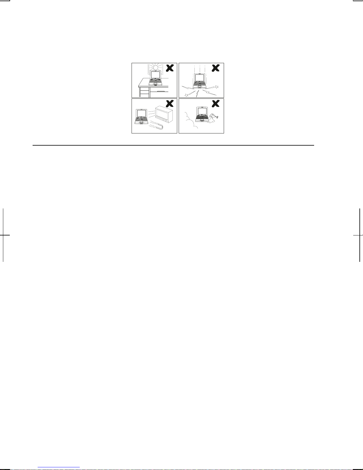
• Do not expose the computer to direct sunlight.
• Try to avoid dusty environments.
• Keep the computer away from any magnetic devices and TVs.
• Keep the computer away from excessive humidity or fluids such as rain, snow,
water spray, juice, coffee, steam, etc.
• Do not move the computer from an extremely cold place to an extremely warm
place. A temperature difference of more than 10°C(18°F) will cause
condensation inside th e unit, which may cause damage.
• Do not block or cover slots or openings on the cabinet. These protect the
computer from overheating.
• Care should be exercised when using on heat sen sitive surfaces or your lap a s
the base of this computer will get hot.
Usage
• Never push any objects ofany kind into cabinet openings. Theymaytouch
dangerous voltage points or short parts that could result in fire or electrical
shock.
• Turn off the computer before installing or removing a peripheral device (except
when connecting USB devices, IEEE1394 devices and PC cards).
• Check the AC power cord and power connectors periodically for damage.
Replace the power cord immediatelyif damage is found.
• Never subject your computer to sudden shocks or extreme vibration.
ix
Page 11
• Do not drop the computer nor hit it with other equipmen t.
• Do not scratch the surface of the LCD screen.
• Turn off the computer and disconnect the AC power cord before cleaning.
Battery Precautions
CAUTION
DANGER OF EXPLOSION IF BATTERY IS INCORRECTLY REPLACED.
REPLACE ONLY WITH THE SAME OR EQUIVALENT TYPE
RECOMMENDED BY THE MANUFACTURER. DISCARD USED BATTERIES
ACCORDING TO THE MANUFACTURER'S INSTRUCTIONS.
Handling
• Never put the battery pack in a fire, as it could explode and cause injury.
• Do not attempt to open or alter the battery pack.
• Do not place the batter y wh ere it might get hotter than 60°C (140°F).
• Do not allow metal objects such as jewelry to short across the battery terminals,
as it could heat up and explode.
• Do not allow liquids to come in con tact with the battery pack.
• Avoid dropping the pack or other violent shock.
• Do not solder anything to the batter y terminals.
Charging
• Charge the battery pack only with the AC adapter included with your computer.
x
Page 12

Discharging
• Do not use the battery pack for any purpose other than powering the computer.
Storage
• Stor e the batter y pack in a cool and dry place. Never allow the temperature to
exceed 60°C (140°F) during storage.
• Recharge the battery pack after storage, before use.
Modem Precautions
• Never install telephone wiring during a lightning storm.
• Never install telephone jacks in wet locations unless the jack is specifically
designed for wet locations.
• Never touch uninsulated telephone wires or terminals unless the teleph one line
has been disconnected at the network interface.
• Use caution when installing or modifying telephone lines.
• Avoid using the telephone during a lightning storm. Theremay be a remote
risk of electricshock from lightning.
• Do not use the telephone to report a gas leak while in the vicinity of the leak.
Wireless LAN Precautions
• Do not communicate with wireless LAN in specific environment where radio-
susceptible equipments are nearby such as on airplanes, in hospital, etc.
• Do not touch the antennas while communica ting.
• Keep the distance at least 20cm between the antennas and your body while
communicating..
xi
Page 13

About This Manual
Notice
Information in this manual is subject to change without notice and does not represent a
commitment on the part ofSHARP Corporation.
SHARP Corporation shall not be liable for technical or editorial errors or omissions
contained herein; nor for incidental or consequential damages resulting from the furnishing,
performance, or use ofthis material.
SHARP stronglyrecommends that separate permanent written records be kept of all
important data. Data may be lost or altered in v irtually any electronic memory product under
certain circumstances. Therefore, SHARP assumes no responsibility for data lost or
otherwise rendered unusable whether as a result ofimproper use, re pair s, defects, battery
replacement, use after the specified battery life has expired, or any other causes.
SHARP assumes no responsibility directly or indirectly, for financial losses or claims from
third persons resulting from the use of this product and any of its functions, such as stolen
credit card numbers, the loss of or alteration of stored data, etc.
Edition
1st Edition, June 2002.
Copyright
© 2002 SHARP Corporation
This document contains or refers to proprietary information which is protected bycopyright.
All rights are reserved. Copying or other reproduction of this document is prohibited without
the prior written permission of SHARP Corporatio n.
Trademarks
Intel and Pentium are registered trademarks, and SpeedStep is a trademark o fIntel
Corporatio n.
IBM is a trademark of International Business Machines Corporation.
Microsoft, MS-DOS, Windo ws, and the Windows Logo are registered trademarks of
Microsoft Corporation.
WinDVD is a trademark of Inter Video, Inc.
All other brand and product names are trademarks or registered trademarks oftheir
respective holders.
xii
Page 14

Recording Important Information
For future reference, please record the following information in the spaces
provided below.
Model Number:
Serial Number:
Date of purchase:
Dealer’s Name:
Place of purchase:
Password:
The serial number is pr inted on a sticker located on the bottom of the computer.
xiii
Page 15

Manual Conventions
This manual uses a set of style conventions described below.
Notes and Cautions are italicized with icons:
A note icon informs you of a special technique or information that may
help you perform a task or better understand a process.
A caution icon alerts you to something that may cause problems or
damage to hardware, software or data.
Key Labels on the Keyboard, when referred to in theinstructions, are shown in
boldface:
Press Enter to continue.
When two or more keys are pressed simultaneously, the key labels are separated by
a plus (+) sign:
Restart your computer by pressing Ctrl+Alt+Delete.
Sample Entries are shown in upper cases of different typeface.
C:\WINDOWS\SYSTEM
Words/Texts on Screen, such as window titles or possible par ameters, are
italicized:
Double-click this icon to displaythe Power Properties window.
SettheitemtoEnabled.
Screens reproduced in th is manual may differ slightly from the screens you see on
your computer.
Section Titles in other parts of this man ual are italicized:
Refer to Installing Battery Pack section of Chapter 1.
xiv
Page 16

Table of Contents
Notice for Users in USA........................................................................................i
Notice for Users in the UK and Ireland................................................................ iv
Notice for Users in Europe...................................................................................vi
Safety Precautions............................................................................................... ix
About This Manual.............................................................................................xii
Recording Important Information......................................................................xiii
Manual Conven tions.......................................................................................... xiv
Table of Conten ts ............................................................................................... xv
Overview of Computer...................................................................................... xvii
Quick Setup
Installing Battery Pack ......................................................................................1-1
Connecting AC Power.......................................................................................1-2
Setting Up Windows..........................................................................................1-4
Turning Off Your Computer..............................................................................1-7
Basic Operations
Choosing Power Source.....................................................................................2-1
Resetting the System..........................................................................................2-3
Using the Glide Pad...........................................................................................2-4
Usin g the Keyboard...........................................................................................2-6
Using an Optical Drive ...................................................................................... 2-7
Writing Data to CD-R/RW..............................................................................2-10
Watching DVD-ROM Video ...........................................................................2-11
Controllin g Audio...........................................................................................2-15
Adjusting the Display...................................................................................... 2-17
Sharing the Computer (Windows 2000)........................................................... 2-20
Sharing the Computer (Windows XP Professional) .......................................... 2-21
Battery and Power Management
Batter y Pack......................................................................................................3-1
Optional Add-on Battery Pack...........................................................................3-6
Power Management.........................................................................................3-10
xv
Page 17

Peripherals
Usin g Peripherals...............................................................................................4-1
Using Option al External FloppyDisk Drive Unit...............................................4-3
Display..............................................................................................................4-6
AudioSystem.....................................................................................................4-7
USB Device.....................................................................................................4-11
PC Card...........................................................................................................4-12
Printer .............................................................................................................4-15
Using IEEE 1394 Devices................................................................................4-16
Communication Functions
Built-in Modem .................................................................................................5-1
LAN unit...........................................................................................................5-6
Wireless LAN....................................................................................................5-9
Setup Utility
Running the Setup Utility ..................................................................................6-1
Main Menu........................................................................................................6-3
Advanced Menu.................................................................................................6-4
Security Menu....................................................................................................6-5
Boot Menu.........................................................................................................6-7
Exit Menu..........................................................................................................6-7
Appendixes
Memory Module...............................................................................................A-1
Installing Weigh t Saver ....................................................................................A-4
Maintenance and Care......................................................................................A-6
Re-in stallation Instructions.............................................................................A-11
Specifications..................................................................................................A-16
Troubleshooting
Index
xvi
Page 18
Overview of Computer
Each number after an arrow indicates the page r eferring to the part. Actual
appearance of your computer may be slightly different depending on the model.
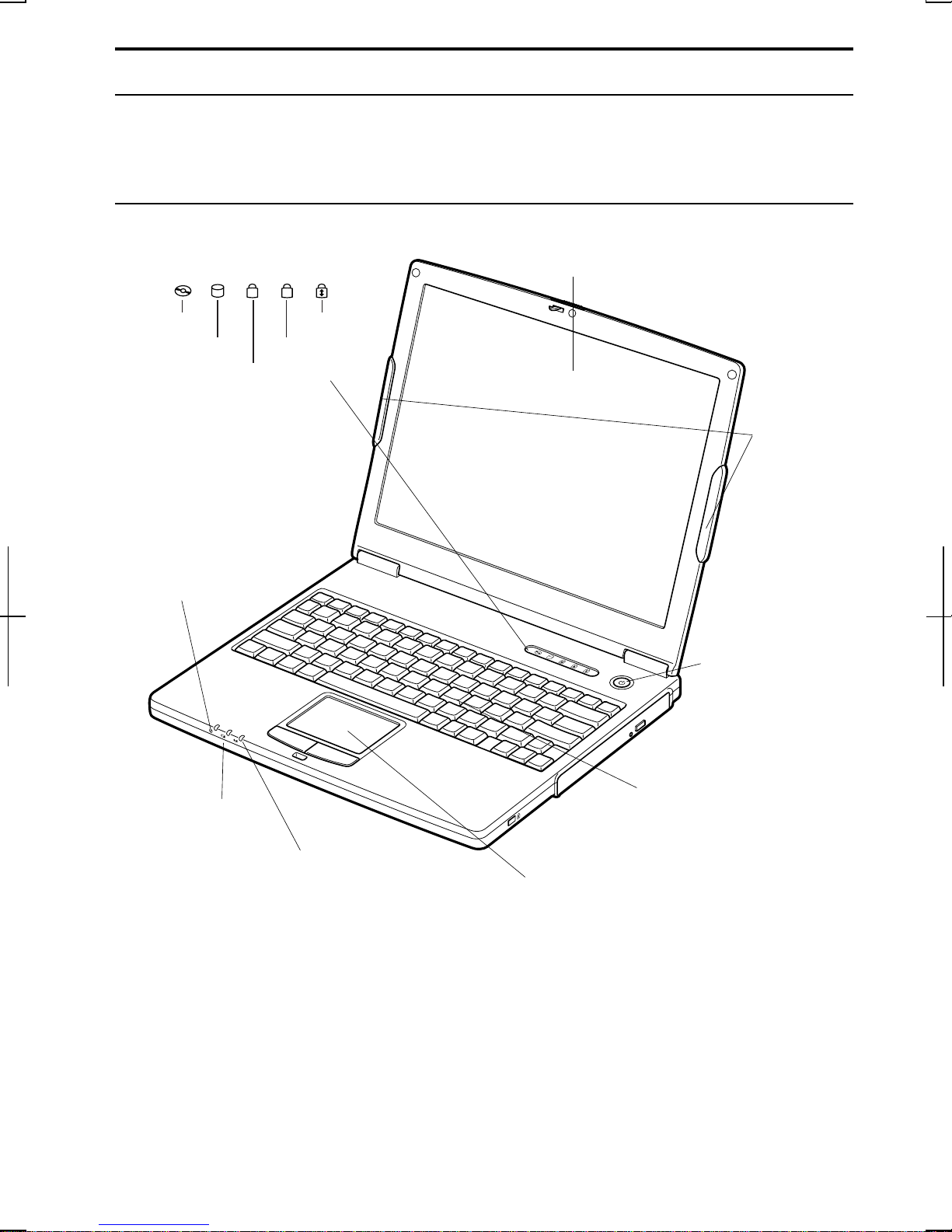
Front
LCD Screen
Status Indicators
N
Hard Disk
Num Lock
A
Scroll LockOptical Drive
Caps Lock
→2-17
Wireless
LAN
Antennas
→5-9
Power Indicator
→2-1
Battery Indicator
→2-1
Antenna Indicator
→5-9
Power Button
Keyboard
→2-6
Glide Pad
→2-4
xvii
Page 19
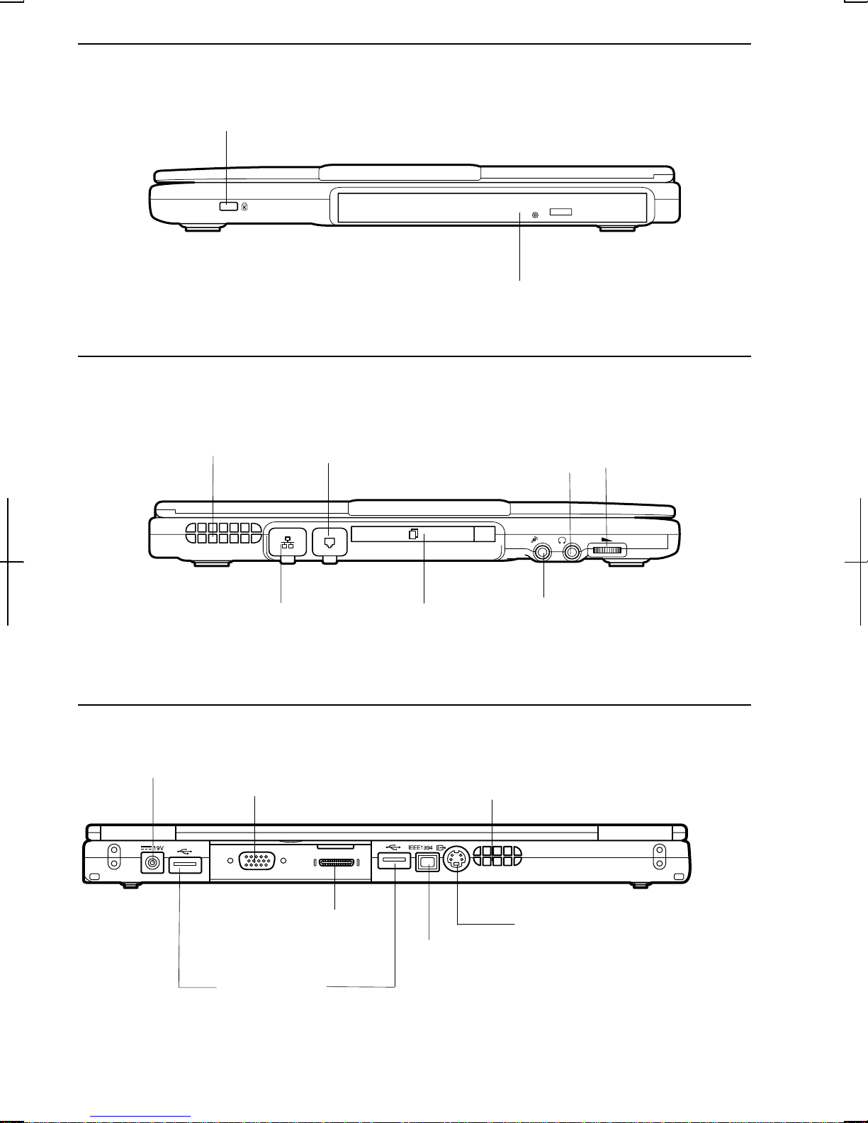
Right
-
Left
Security Slot
→A-9
Optical Drive
→2-7
Ventilation Openings
→ix
LAN Jack
→5-6
Rear
AC Adapter Jack
→1-2
Modem Jack
→5-2
PC Card Slot
→4-12
External Monitor
Port →4-6
Audio Output Jack
(S/PDIF Compliant)
7
→4
Microphone Jack
→4-10
Ventilation Openings
→ix
Volume Control
→2-15
Parallel Port
→4-15
USB Ports
→4-3,4-11,4-15
xviii
S Video Output
Jack →2-13
IEEE1394
Connector
→4-16
Page 20
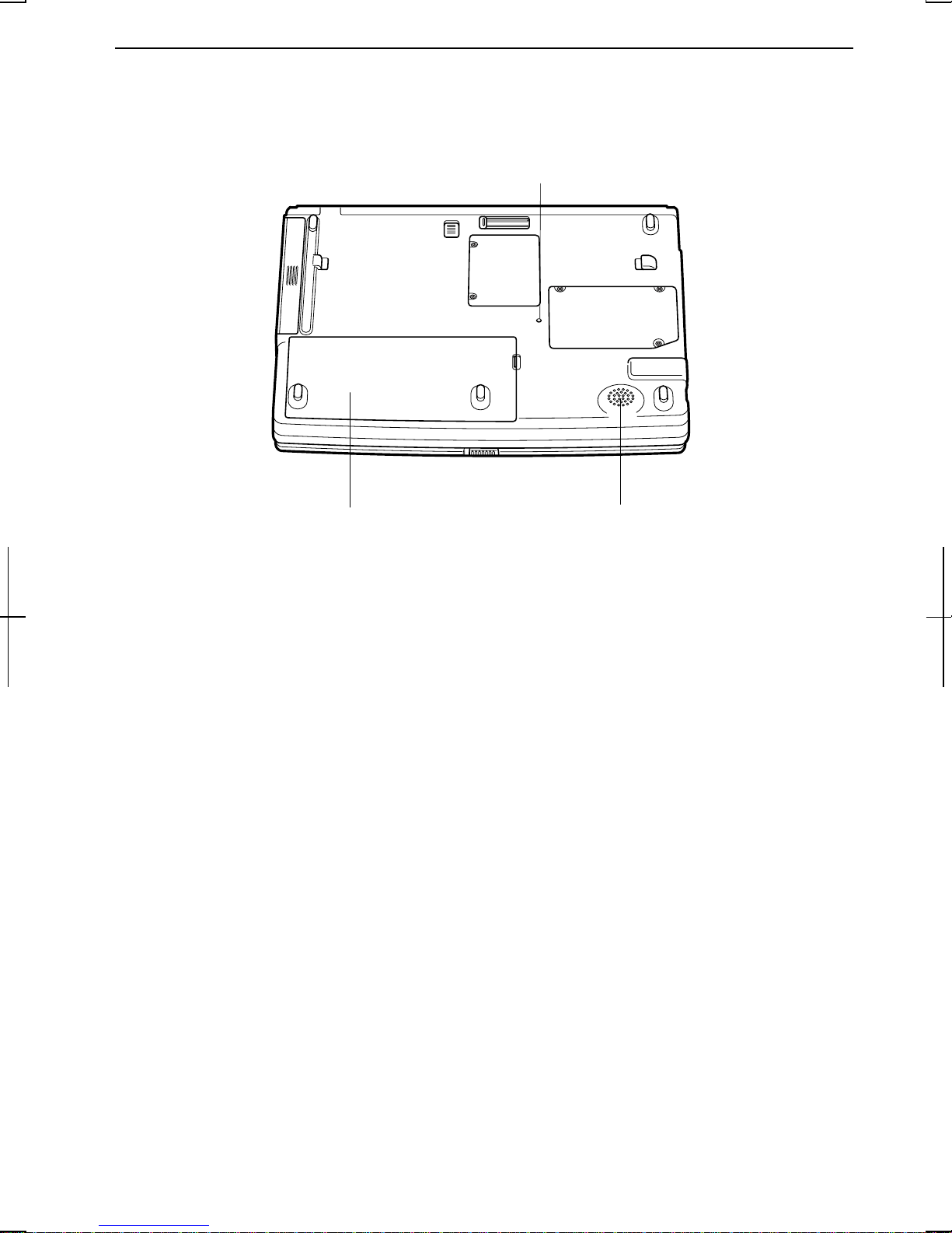
Bottom
Reset Switch
→2-3
RESET
Battery Pack
→3-1
Speaker
xix
Page 21

xx
Page 22
CHAPTER 1
Quick Setup
Your computer is designed and pre-configured for easy setup and use. This chapter
describes the steps to get your computer up and running as quickly as possible.
Read this chapter first.
Installing Battery Pack
Your computer is powered with either the rechargeable batterypack or AC power.
See the next chapter for more information on power sources. Before using th e
1
computer for th e first time:
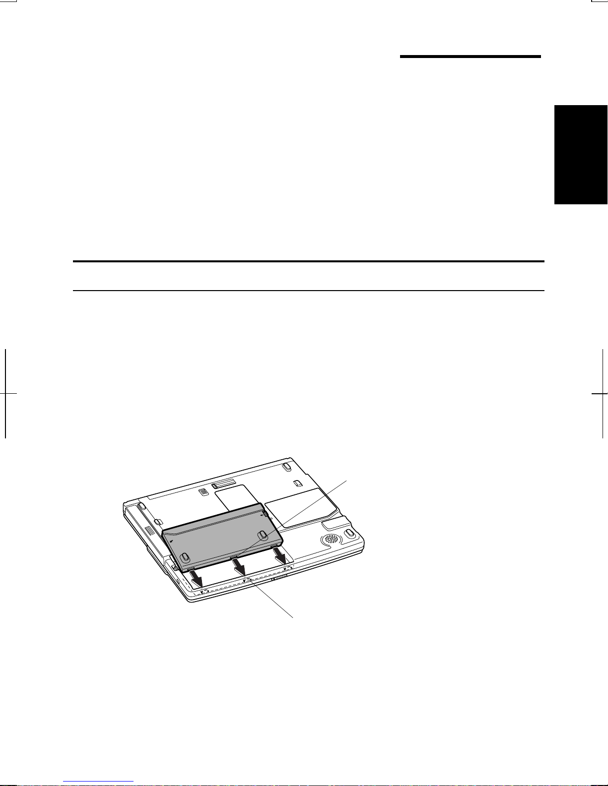
1. Place the computer upside down.
2. Insert th e batterypack into the computer by matching the projected parts of
the battery to th e notched parts on the computer.
Projected Part
Notched Part
1-1
Page 23
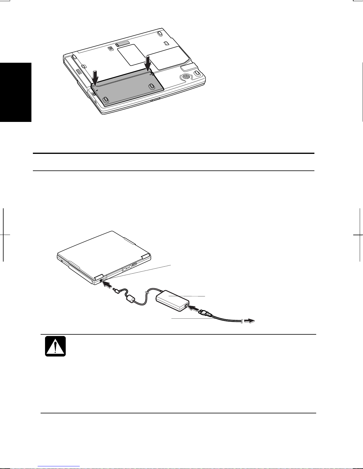
3. Push the battery pack until you hear the clicking sound.
1
4. Turn over your computer and go to the next section.
Connecting AC Power
1. Plug the AC adapter cable to the AC adapter jack on the rear side of your
computer.
2. Plug the AC power cord into the AC adapter.
3. Plug the AC power cord into a wall outlet.
AC Adapter Jack
AC Power Cord
• Always use the AC adapter included with the computer or the optional
one (may not be available in some countries). Using other AC
adapters may damage the computer.
• Always hold the AC power cord by its plug when removing it from the
wall outlet. Never pull on the cord.
AC Adapter
To Wall Outlet
• When using the computer for the first time, be sure to connect it to AC
power. If using the battery instead, you may not be able to complete
the Windows setup if the battery does not have enough power.
1-2
Page 24
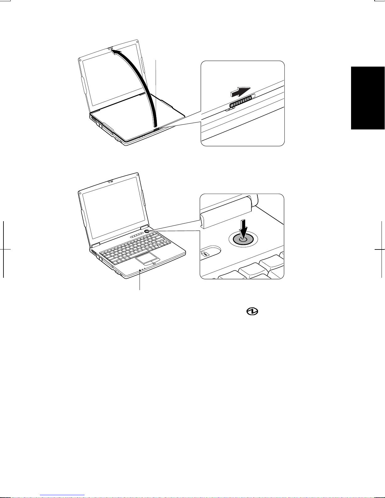
4. Slide the displaycover lock lever to th e right until the displaycover releases,
and raise th e cover.
Display Cover Lock Lever
5. Press the power button to turn on your computer.
1
Power Indicator
When you turn on the computer, the power indicator ( ) turns green, the
computer goes through a self test to detect any problems, and Windows setup
process starts. See the next page.
1-3
Page 25

Setting Up Windows
Before starting the setup of Windows, you must select the operating system. There
are two kinds of operating system available: Windows 2000 and Windows XP
Professional. You can choose one of them when starting to use the computer for
the first time.
1
If you choose Windows 2000, the setup steps are:
• Accepting license agreement
• Configuring the name ofyou and your organization
• Configuring the setting of your computer within the work group
• Completing configuration
If you choose Windows XP Professional, the setup steps are:
• Configuring your location, language an d keyboard
• Configuring your time zone
• Accepting license agreement
• Naming your computer
• Creating an account
• Completing configuration
To setup Windows, follow the instructions on the screen. See also the Windows
manual. It takes approximately 15-20 minutes to complete the entire setup
process.
• Do not turn off the computer until completing Windows setup. If you
turn it off, you cannot set up Windows later.
• Be sure to connect the computer to AC power. If using the battery
instead, you may not be able to complete the Windows setup if the
battery does not have enough power.
• Do not connect any peripheral devices to your computer unless
Windows setup completes. Otherwise your computer may malfunction.
1-4
Page 26

• If the display turns off, some power management may function. In this
case, press any key to resume your computer from the power
management.
• If you cannot operate the keyboard or the touch pad, press the power
button for more than four seconds to turn off the computer. Be sure
that the battery indicator turns off; then, after more than 10 seconds,
press the power button to turn it on again.
For Users Outside UK
After completing Windows setup, set your date and time. Double-click the time
appearing on the right of the taskbar to open Date/Time Properties (Windows
2000) or Date and Time Properties (Windows XP Professional) dialog box.
Confirm Time Zone is correctly selected, an d set date and time.
For UK Users
After completing Windows setup, double-click README FIRST (for U.K.users)
icon on the desktop and follow the instructions in it to customize the setting
suitable for UK users. Th en set date and time in Date/Time Properties (Windows
2000) or Date and Time Properties (Windows XP Professional) dialog box.
Properties Dialog Box in Windows 2000
In this manual, you will often see the expression “XXX Properties dialog box.” A
dialog box is a win dow containing text boxes, check boxes, button s, etc., with
which you can send commands to Windows or other application pr ograms. To
open the properties dialog boxes, click the Start buttontoopentheStart menu;
1
then, select Settings - Control Panel and double-click the XXX icon. Some of the
dialog boxes you will use often are:
• Display
• Phone and Modem Options
• Mouse
• Power Options
• System
Properties Dialog Box in Windows XP Professional
In this manual, you will often see the expression “XXX Properties dialog box.” A
dialog box is a win dow containing text boxes, check boxes, button s, etc., with
which you can send commands to Windows or other application pr ograms.To open
the properties dialog boxes, click start - Control Panel. There are two types of
view for the Control Panel. One is Category view, and the other is Classic view. If
1-5
Page 27

1
you select Category view, you can choose the category which may be related to
what you want to do, then, choose your task by clicking it. If Classic view
selected, all the icons appear simultaneously. You can open a property dialog box,
or similar window, for the component or feature represented by that icon, by
double-clicking it.
1-6
Page 28

Turning Off Your Computer
When you’re finished using your computer, turn it off with the following ways:
• With a power button (Windows 2000)
Before using this way, confirm that Power Off is selected in When I press the
power button on my computer in Advanced tab of Power Options Properties
dialog box.
• With a power button (Windows XP Professional)
Before using this step, confirm that Shut down is selected in When I press the
power button on my computer in Advanced tab of Power Options Properties
dialog box.
• From the Start menu (Windows 2000)
1. From the Start menu, select Shut Down….
2. In the Shut Down Windows dialog box, select Shut down from the pull down
menu, and click OK.
1
• From the start menu (Windows XP Professional)
1. Click start – Turn Off Computer.
2. In the Turn off computer dialog box, click Turn Off.
Close the cover to keep the screen and keyboard clean and protected.
If you have not saved a file, a dialog box will appear asking whether you
want to save it.
• Do not turn off or reset the computer while the hard disk indicator,
optical drive indicator, or the indicator on the optional external
floppy disk drive is lit. Doing so may damage or even wipe out the
data.
• Before turning it back on, wait at least ten seconds after turning off
the computer. Turning the power off and on in rapid succession can
damage the computer’s electrical circuitry.
1-7
Page 29

1
1-8
Page 30
CHAPTER 2
Basic Operations
This chapter describes the basic operations of your computer.
Choosing Power Source
You can use the computer with one of the following power sources:
• AC power from a wall outlet
Use AC power whenever possible; rely on the battery only when AC power is
not available.
2
• Rechargeable batter y
Your computer is equipped with a standard battery. You can also use an
optional battery. See Chapter 3 for battery information.
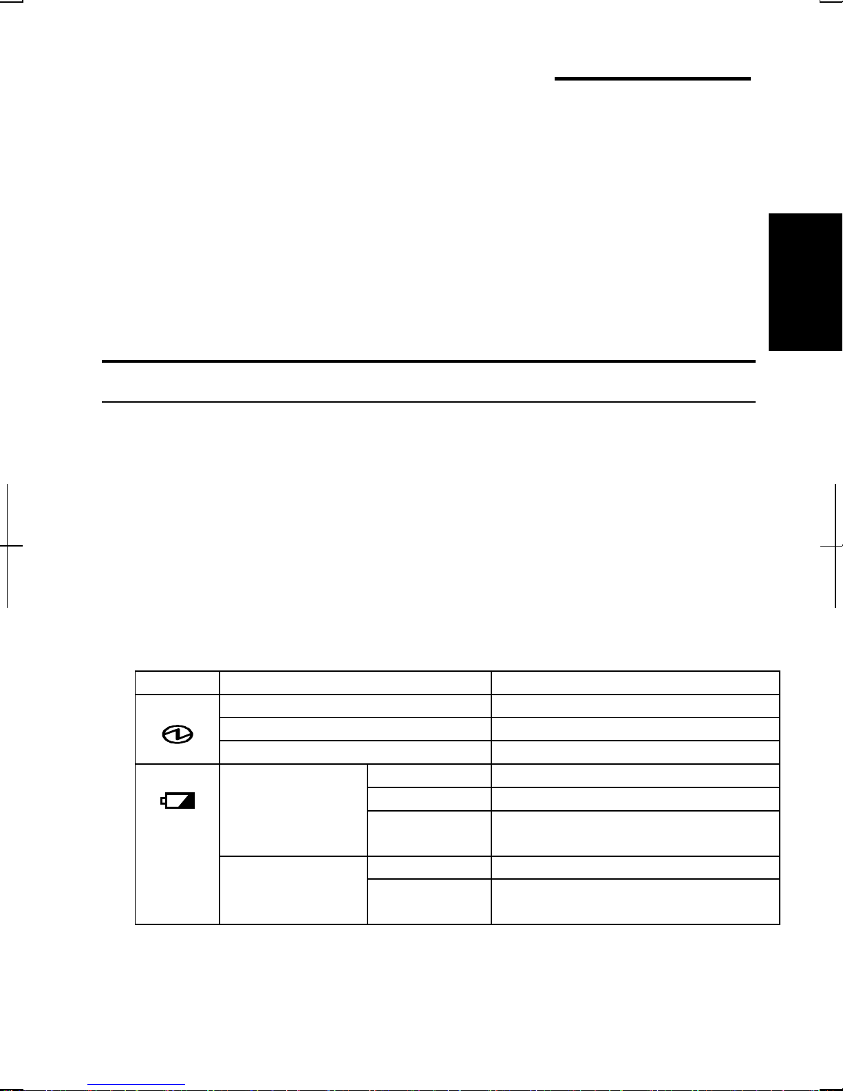
About the Power Indicators
The following indicators showth e power status of your computer.
Indicator Light Meaning
Power On (green) Operating
Blinking (green) In System Standby
Off Powered off or in System Hibernate
Battery On (green) Fullycharged
When Connected
to AC Power
Battery
On (orange) Being charged
Blinking
(orange)
Off Has powerWhen Run by
Blinking (red) Almost completely discharged
In abnormal state. Remove the
battery pack and install it again .
(The warning beep sounds)
2-1
Page 31

Battery indicator is always off when the computer is turned off and not connected
to AC power.
• When the battery is hot, the battery indicator may turn off and stay off
until the battery becomes cool.
• For more information on System standby/hibernate, see Chapter 3.
Using the AC Adapter
When connected to a wall outlet, the AC adapter provides power for operation and
2
charges the battery. The AC input voltage can range from 100 to 240 volts so that
you can use the computer with the appropriate plug adapter.
The AC power cord included with the computer is appropriate for the
voltage used in the area in which you purchased your computer. If you
attempt to connect the computer to a wall outlet other than in this area,
check the voltage of the outlet and use an AC power cord appropriate
for the outlet. Consult local service staff if you are unsure.
2-2
Page 32

Resetting the System
You may need to restart the system if the computer becomes inoperable or after
adding new hardware or software. When the message appears after the
installation, click OK, Yes,etc.torestartWindows.
You can also restart Windows 2000 from the Start menu. Select Shut down…;
then, Restart. You can restart Windows XP Professional by clicking start - Turn
Off Computer; then, Restart.
Warm Boot (Software Reset)
If the system is locked up because of a software problem, you can reset or reboot
the system by pressing the Ctrl+Alt+Del keys simultaneously an d follow the
instructions on the scr een.
Resetting may cause data loss. Use the resetting process only if the
normal Windows Shut Down does not work because of software
malfunction. Although resetting will not damage the system, you may
lose the data you are processing.
Power Switch
You can turn off the computer with the power button if you encounter har dware or
software problems which lock up the system. In this case, press the power button
for more than four seconds.
Reset Switch
If you cannot turn off the computer by pressing the power button, you can use the
2
reset switch on the bottom of your computer. To r eset the system, insert a narrow
object in to the small h ole to press the switch .
RESET
Reset Switch
2-3
Page 33

Using the Glide Pad
Your computer is equipped with an integrated pointing device called a glide
pad. Using th e glide pad, you can move the pointer, select an item from a
menu, and perform other tasks in the same wayyou would with a mouse.
2
Glide Pad
• Do not hit or scratch the surface of the glide pad with pointed objects
(such as a ballpoint pen).
• Do not operate the glide pad with a moist finger. This may cause the
glide pad to operate incorrectly.
Using the Glide Pad
Take a moment to become familiar with how the glide pad works.
Place Your Fingertip
Place your left or right hand next to the glide pad, resting your wrist natura lly in a
relaxed mann er. Place your thumb or finger on the glide pad.
Move Your Fingertip
The rectangular pad of the glide pad acts like a miniature duplicate of the display.
As you slide your fingertip across th e pad, the pointer on the screen moves in the
same direction across the screen. The glide pad is very sensitive, so you do not
have to exer t much pressure on the pad. The glide pad will r espond to a light touch
from your fingertip.
2-4
Page 34

Click, Double-click, and Right-click
To click or double-click, you can use the left button just like that of a mouse.
Instead of clicking the left button, you can also just tap gently anywhere on the
rectangular pad. For right-clicking, you must use the right button.
Drag and Drop
You can move icons or windows by using “drag and drop” below:
1. Position the pointer over the object.
2. Press the left button; do not release it.
3. Holding down the button, move the pointer. The object moves together with
the pointer.
4. Release the button when the object reaches its destin ation.
Or you can tap the pad twice instead of pressing the left button in step 2.
Scroll
You can scroll through information in a list or in a document byusing the glide
pad. To viewinformation vertically, place your finger on th e most righ t part of th e
glide pad and slide your finger up an d down. To view horizontally, place your
finger on the bottom part of the glide pad and slide your finger to the left or the
right. This procedure works only in limited applications.
Changing the Configuration
In the Mouse Properties dialog box, you can change the configuration of the glide
pad, such as swapping left and right buttons, changing the pointer size, etc.
Double-click
icon on the taskbar.
2
2-5
Page 35

Using the Keyboard
Your computer, equipped with the Windows Enhanced Keyboard, provides all the
functionality of a full-sized desktop keyboard.
Special Keys
2
Windows Key
Application Key
System Function Keys
When pressed together with the Fn key, function keys set specific system
parameters. Th is combin ation is sometimes refer red to as “hot keys”.
Fn + F1 Turns the wireless LAN antenna on and off. This key
combination functions only when Wireless LAN in Security
menu in the Setup Utility is set to Enabled.
Fn + F5 Rotates displaymode in between LCD only, CRT only, and
simultaneously display.
Fn + F6 Decreases the LCD screen brightness.
Opens the Windows Start menu.
Opens an application-specific short-cut menu
equivalent to right-clickin g.
2-6
Fn + F7 Increases the LCD screen brightness.
Fn + F11 Turns on and off the LCD screen.
Fn + F12 Forces the computer into System standby. See Power
Management of Chapter 3 for more information.
Page 36

Using an Optical Drive
With the optical dr ive, you can r ead data from CD and write data into CD-R/RW.
Furthermore, you can enjoy a movie etc, with the DVD-ROM disk.
CAUTION FOR LASER
Use of controls or adjustments or performance of procedures other
than those specified herein may result in hazardous radiation exposure.
Maximum output and wavelength of the laser:
144mW, 784nm(CD-R/RW)
6mW,662nm(DVD-ROM)
CLASS1LASER PRODUCT
LASER KLASSE1
Handling Disks
2
• Do not write on either side of th e disk, par ticularly the non-label side. Data is
read from th e non-label side. Do not mark this surface.
• Keep your disks away from direct sunlight, heat and excessive moisture.
• Always hold th e disks by the edges. Fingerprints, dirt or water on the disks can
cause noise or mistracking. If a disk is dirty or does n ot play properly, clean it
with a soft, dry cloth, wiping straight out fr om the cen ter, along the radius.
2-7
Page 37

Inserting a Disk
1. Make sure the optical drive indicator does not light on; then, press the eject
button to open the dr ive tray slightly.
2
Optical drive Indicator
Eject Button
2. Gentry pull out the tray.
3. Place your disk, label side up, onto the tray and slightly press th e center of the
disk until it clicks into the place.
2-8
Page 38

4. Gently push the tray back into the computer.
• Do not leave the tray pulled out. Also, avoid touching the lens in the
tray. If the lens becomes dirty, the disk may malfunction.
• Do not wipe the lens with materials with rough surface (such as paper
towels). Instead, use a cotton swab to gently wipe the lens.
Removing a Disk
1. Make sure the optical drive indicator is not lit and press the eject button to
open the optical drive tray slightly.
2. Gentry pull out the tray.
3. Remove the disk from the tray by holding its edge.
2
4. Gently push the tray back into the computer.
Make sure the optical drive indicator is not lit or blinking before
pressing the eject button.
2-9
Page 39

Writing Data to CD-R/RW
You can use a CD-R or a CD-RW disk to write data on. CD-RW is an erasable
disk onto wh ich you can write data and from which you can erase data. CD-R is
non-erasable disk onto which you can write data only once. If free space remains,
you can add data until the disk is full.
To write data, run the application called Drag’nDropCDinstalled with your
computer. See the online help of Drag’nDropCDfor the details.
2
Before writing to CD-R/RW, follow the instructions below:
• Connect the AC adapter. If t he battery is discharged, writing to the
disk will be stopped and the write process will fail.
• Disable the power management. See Power Management of
chapter 3.
• Close any applications which are unnecessary for writing, or will
start automatically when the computer is turned on.
• Disable the screen saver.
2-10
Page 40

Watching DVD-ROM Video
C
n
You can enjoy watching DVD-ROM video on your computer using the application
called Win DVD. See online help of Win DVD for more details.
• Before watching DVD-ROM video, followthe instructions below:
onnect the AC adapter. If the battery is discharged, the operatio
•
will stop.
• Disable the power management. See Power Management of
Chapter 3.
• Close any applications which are unnecessary.
This product incorporates copyright protection technology that is
protected by method claims of certain U.S. patents and other
intellectual property rights owned by Macrovision Corporation and
other rights owners. Use of this copyright protection technology must be
authorized by Macrovision Corporation, and is intended for home and
other limited viewing uses only unless otherwise authorized by
Macrovision Corporation. Reverse engineering or disassembly is
prohibited.
(Apparatus Claims of U.S. Patent Nos. 4,631,603; 4,577,216;, 4,819,098
and 4,907,093 licensed for limited viewing uses only.)
Make sure to remove the DVD-ROM disk from the drive when you finish
watching it. If you turn off the computer with the disk inserted in the
drive, the drive may not be recognized when the computer is turned on
again.
2
Changing Region Code
Each DVD-ROM disk has a region code w hich prevents playback of the disk in
certain region. Region code appears on the top of the disk.
When shipped from the factory, the region code of your DVD-ROM drive is set to
the region code applicable to your area. (may not be available in some areas)
2-11
Page 41

Available region codes are:
Region Code Area
1 U.S.A, Canada, U.S. Territories
2 Europe, South Africa, Middle East, Japan
3 Southeast Asia, East Asia(including Hong Kong)
4 Australia, New Zealand, Pacific Islands, Central
America, Mexico, South America
5 Former Soviet Union, Indian Subcontinent, Africa
6 China
2
To change the region code:
1. Insert a DVD-ROM disk into the drive.
If the region code of your disk is different from that of your DVD-ROM
drive, the message “Playback of content from this region is not permitted”
appears.
2. Click OK. Confirm Region dialog box appears.
3. The region code currently selected is checked in the left box. Region code of
your disk is checked in the right box. If you want to change th e code an d play
your disk, click OK.
On some DVD-ROM disk, plural region codes appear. In this case,
some region codes appear to be checked in the right box. Check
carefully which one is the appropriate region code in your country.
Use Parental Control
If you want to set the parental control to prevent your children from watching an
inappropriate movie, click
box, and select Parental Control tab. Select the control level and set your password
if you want. See online help of WinDVD for more details.
Disabling LCD Optimization
Your computer optimizes the screen visibility automatically when you play a DVD
video. When the screen is not appropriate to y o u, you can disable the LCD
optimization function. Click
box, and select Display tab; then, uncheck LCD Optimization.
2-12
icon of WinDVD to open the Properties… dialog
icon of WinDVD to open the Properties… dialog
Page 42

Displaying Video on Your TV Set
You can connect a television set with S-Video input to y o ur computer and enjoy
DVD video on a big display.
• Before connecting the television set, disconnect the external monitor.
• Connect the computer and the television set directly. Otherwise, the
screen may be distorted.
Connecting a TV Set
1. Turn off the computer and the television set.
2. Connect the television set to your computer.
Audio
Output
Jack
S Video
Output
Jack
To Audio Input Jacks:
WhitePlugtoLeft
RedPlugtoRight
Stereo
Mini
Plug
To S Video Input Jack
2
3. Turn on the computer and the television set.
4. Right-click somewhere on the Windows desktop.
5. Click Properties from the pull-down menu.
6. Click Advanced…inSettings tab.
7. Select Intel® Graphic Technology; then, click Graphic Properties.
8. Select TV and click OK three times.
9. If you can see the screen image on the television set, click Yes.
10. Click OK and close Display Properties dialog box.
2-13
Page 43

Before disconnecting the television set, be sure to turn off the computer and the
television set.
After disconnecting the television set, set back the display property
following the steps 4 to 6.
Enjoying Dolby Digital Audio
Your computer is Dolby Digital compliant. If you connect Dolby Digital
2
complian t audio equipment or headphones, you will have an audio output similar
to a big theater.
For connection, refer to Audio System of Chapter 4.
WinDVD is equipped with Dolby HeadphoneTMproperties.You can
enjoy Dolby sound just by connecting normal headphones. To set this
function, click
online help of WinDVD for more details.
icon and select DolbyHeadphone tab. Refer to the
2-14
Page 44

Controlling Audio
You can control the output volume of your computer by the following steps.
With the Volume Control
Turn the volume control on the left side of the computer backward you to increase
the volume. Turn it toward you to decrease the volume.
Increases
the volume
Decreases
the volume
2
In Windows 2000
1. Click Start – Settings - Control Panel.
2. Double-click Sounds and Multimedia icon.
3. In Sounds and Multimedia Properties dialog box, slide the lever to control
the output volume.
4. Click OK and close Control Panel window.
Check the box of Show volume control on the taskbar on Step 3 above.
Next time you find the speaker icon on the taskbar, and it is easy to
control volume.
If you want to control the output volume of each source individually:
1. Click Start - Settings – Control Panel.
2. Double-click Sounds and Multimedia icon.
3. In Sounds and Multimedia Properties dialog box, click Volume of Sound
Playback in Audio tab.
4. Slide the lever of the source that you want to control.
5. Close the dialog box, then; click OK and close Control Panel window.
2-15
Page 45

If you Control;
2
Wave
SW Synth
CD Player
In Windows XP Professional
1. Click start - Control Panel.
2. Click Sounds, Speech, and Audio Devices; then, Sounds and Audio Devices.If
Classic view is selected, double-click Sounds and Audio Devices icon.
3. In Sounds and Audio Devices Properties dialog box, slide the lever to control
the output volume.
4. Click OK and close the dialog box; then Control Panel window.
Check the box of Place volume icon in the taskbar on Step 3 above.
Next time you find the speaker icon on the taskbar, and it is easy to
control volume.
Controlling th e volume of CD/DVD or WAVE file
Controlling th e volume of MIDI file
Controlling th e volume of CD/DVD if the application selects
analog playback
If you want to control the output volume of each source individually:
1. Click start - Control Panel.
2. Click Sounds, Speech, and Audio Devices; then, Sounds and Audio Devices.If
Classic view is selected, double-click Sounds and Audio Devices icon.
3. In Sounds and Audio Devices Properties dialog box, click Advanced…of
Device volume.
4. Slide the lever of the source that you want to control.
5. Close the dialog box, then; click OK and close Control Panel window.
If you control:
Wave
SW Synth
Controlling th e volume of CD/DVD or WAVE file
Controlling th e volume of MIDI file
2-16
Page 46

Adjusting the Display
You can adjust the brightness, resolution , and number of colors of the internal
LCD display.
Changing Brightness of Display
Press Fn and F6 keys simultaneously to decrease the brightness of the display.
Press Fn and F7 keys simultaneously to increase it.
Changing Resolution and Number of Colors
When shipped, your computer is set to the default resolution and color. The default
resolution is 1024 x 768 at 16 million colors. To change th e resolution and the
number of colors, perform th e following:
1. In the Display Properties dialog box, select Settings tab.
2. Select the number of th e colors in the Colors or Color quality, and select the
resolution in Screen area or Screen resolution. Refer to the table of the next
page.
3. Click OK twice; then, Yes. (Windows 2000)
Click OK; then, Yes. (Windows XP Professional)
2
2-17
Page 47

Resolutions and Colors you can choose
2
Resolution
640 x 480
(Windows 2000 only)
800 x 600 256
1024 x 768 256
1280 x 1024
1400 x 1050
1600 x 1200
(*1)
Available only in Windows 2000.
(*2)
Available only when the sc reen is displayed to an external mo nito r.
(*3)
On the internal LCD screen, the number of colors in this mode is made using
(*2)
(*2)
(*2)
Numb er of Colors
(*1)
256
64K
(*3)
16M
(*1)
64K
(*3)
16M
(*1)
64K
(*3)
16M
(*1)
256
64K
(*3)
16M
(*1)
256
64K
(*3)
16M
(*1)
256
64K
(*3)
16M
a Dithering algor ithm.
• You cannot switch to a display resolution and number of colors that are not
available.
• In the Colors, High Color (16 b it) means 65,536 (64K)colors, and True
Color (32 bit) means about 16,770,000 (16M)colors.(Windows 2000)
• In the Colo r quality , Medium (16 bit) means 65,536 (64K) colors and
Highe s t(3 2 bit) means about 16,770,000 (16M) colors.(Windows XP
Professional)
2-18
Page 48

Changing Wallpaper and Setting Screen Saver
You can enjoy various desktop patterns or screen savers.
Changing Wallpaper
1. In the Display Properties dialog box, select Settings tab.
2. Select the number of th e colors in the Colors or Color quality, and select the
resolution in Screen area or Screen resolution. Refer to the table of the
previous page.
3. In the Display Properties dialog box, select Background or Desktop.
4. Select an appropriate wallpaper in Select a background picture or HTML
document as Wallpaper or Background.
5. Click OK.
Setting Screen Saver
1. In the Display Properties dialog box, select Screen Saver.
2. Select an appropriate screen saver in Screen saver and set time when screen
saver starts.
3. Click OK.
2
2-19
Page 49

Sharing the Computer (Windows 2000)
For the details, refer to Windows 2000 Professional Quick Start Guide.
Registering New Users to Your Computer
1. Log on to your computer with the name of the administrator.
2. From the Start menu, select Settings – Control Panel.
3. Double-click Users and Passwords icon.
2
4. In Users and Passwords dialog box, check Users must enter a user name and
password to use this computer; then, click Add…..
5. Type a new user’s name and click Next.
6. Type a new user’s password twice; then, click Next.
7. Select the user’s access level and click Finish.
8. Click OK to close the dialog box.
9. Close Control Panel window.
Changing User Name
1. Follow the steps 1 to 3 of the above.
2. In Users and Passwords dialog box, check Users must enter a user name and
password to use this computer; then, double-click the user name you want to
change.
3. Change the name and click OK twice.
4. Click Yes.
5. Type the user name an d its password; then, click OK to log on to the system.
6. Close Control Panel window.
Changing User Password
If you want to change the password of the currently logged-on user;
1. Press Ctrl+Alt+Delete simultaneously.
2. In Windows Security window, click Change Password….
3. Type the old and a new passwords; then, the new password again for
confirmation.
2-20
Page 50

4. Click OK twice.
5. Click Cancel to back to Windows 2000.
If you want to change the passwor d of another user (For administrator only);
1. Follow the steps 1 to 3 on Registering New Users to Your Computer.
2. In Users and Passwords dialog box, check Users must enter a user name and
password to use this computer; then, click the user nameyou want to change
its password.
3. Click Set Password…..
4. Type a new password twice for confirmation.
5. Click OK twice.
Sharing the Computer (Windows XP Professional)
If you are sharing the computer with your colleagues or familymembers, set a user
2
account for each person . Every user can choose their favorite desktop setting, web
site lists, or make their own My Documents folder etc., and save them to their user
accounts. When you turn on the computer, select your user account.
Set a New User Account
1. Click start - Control Panel.
2. Click User Accounts. If Classic view is selected, double-click User Accounts
icon.
3. Click Create a new account.
4. Type a name for the new account and click Next.
5. Select the account type; then, click Create Account. If you have selected a
Limited account, then that user account has limits for using the computer.
See Help and Support Center for more details.
6. Close User Accounts dialog box; then, Control Panel.
If you added a n ew user account(s), you must select which user account you will
log in when you turn on the computer.
2-21
Page 51

Log off the Computer
“Log off” is useful because you do not have to turn off the computer when you
finish your task and pass the computer to another person. There are two ways to
log off the computer, Switch User or Log Off.
If you select Switch User, yo u can pass the computer to another person without
closing your current applications. For example, if you are viewing a Web site, and
your colleague needs to open a program on the computer, use Switch User.You
can then view the same Web site by just switching users after your colleague
2
finishes with the computer.
If you select Log Off, the system will close all your session and you need to save
your files before logging off the computer.
1. Click start - Log Off.
2. Select Switch User or Log Off. If you select Log Off, the dialog box, which
asks you to save your data may appear.
3. Select a new account to start Windows XP again.
If you cannot see Switch User in Log Off Windows dialog box, click
Change the way users log on or off in User Accounts dialog box, and
check Use Fast User Switching and click Apply Options.
Set Password to User Account
You can set a password to each user account to avoid unauthorized use of your
computer. Once you set the password, you need to enter it when you log on to its
account. If you loose the password, you cannot start th e computer with th at user
account, so un necessary password setting can cause tr ouble in starting the system.
Setting Password
1. Click start - Control Panel.
2. Click User Accounts. If Classic view is selected, double-click User Accounts
icon.
3. Select the account you want to set a password to. You will only have this
option if you log onto th e computer with an Administrator account. If you
2-22
Page 52

log on the computer with a limited user account, go to the next step. (You
cannot set a password to another user account.)
4. Select Create a password.
• If the password has been already set, Create a password will not
appear.
• Only an administrator can set a password to another user account.
5. Type a new password.
6. Type the new password again to confirm it.
7. If necessary, type a password hint word to remember the password you set.
8. Click Create Password.
9. Close User Accounts dialog box; then, Control Panel window.
Changing Password
1. Follow the steps 1-2 on the above section.
2. Select the account you want to change, if you log on to the computer with an
Administrator account. If you log on the computer with a limited account, go
to the next step. (You cannot change the password of another user account.)
3. Select Change the password or Change my password.
• If the password has not been set yet, Change the passwor d or Change
my password will not appear.
• Only an administrator can change the password of another user
account.
2
4. Type a new password.
5. Type the new password again to confirm it.
6. If necessary, type a password hint word to remember the password you set.
7. Click Change Password.
8. Close User Accounts dialog box; then, Control Panel window.
2-23
Page 53

2
Deleting Password
1. Follow the steps 1-2 on Setting Password.
2. Select the account you want to delete its password, if you log on to the
computer with an Administrator account. If you log on the computer with a
limited account, go to the next step. (You cannot delete the password of
anotheruseraccount.)
3. Select Remove the password or Remove my password.
• If the password has not been set yet, Remove the password or Remove
my password will not appear.
• Only an administrator can delete the password of another user
account.
4. Type the password you wan t to delete and click Remove Password.Ifyoulog
on to the computer as a member of the Administrators gr oup and want to
delete the password ofanother user account, just click Remove Password.
5. Close User Accounts dialog box; then, Control Panel window.
2-24
Page 54

CHAPTER 3
y
Battery and Power Management
This chapter explains how to manage the computer’s power effectively and use the
battery pack.
In this section, you often see the expression “Power Options Properties
dialog box”. To open the dialog box:
1. From the Start menu, select Settings – Control Panel.
2. Double-click Power Options icon.(Windows 2000)
or
1. Click start - Control Panel.
2. Click Performance and Maintenance - Power Option s in Categor
view or double-click Power Options icon in Classic view.
(Windows XP Professional)
Battery Pack
When not connected to an external power source, your computer operates with the
rechargeable batterypack. The duration of the battery life may be longer if the
3
computer’s Power Management is active. See the next section for power
management.
To keep the battery life long:
• Condition (see “Conditioning the Battery Pack” later in this chapter) the battery
pack if the actual remaining power in your battery is less than what Windows
Power Meter indicates.
• Turn off your computer when you are not using it.
3-1
Page 55

• The duration of the battery will depend on the computer usage. Using
applications, which heavily use the optical drive or external
peripherals, will experience shorter battery life.
• When using the computer for several hours with battery packs, enable
power management and set System hibernate. Refer to the Power
Management section in this chapter.
• When the battery has not been charged, your computer may not
operate properly. Connect the AC power to charge the battery.
Charging the Battery Pack
1. Connect the AC a dapter to the computer. While the battery is being charged,
the battery indicator ligh ts orange.
3
2. When the battery is fully charged, the battery indicator tur ns green. Charging
time may vary according to the status of the computer.
• Battery indicator may turn off even while the battery pack is being
charged. This is because the battery pack is hot, and the charging
stops temporarily. When the battery becomes cool, the charging will
start and the battery indicator will turn on again.
• The battery pack may not be installed correctly if the battery
indicator blinks orange. In this case, turn off the computer, remove
the AC adapter and the battery pack; then, install the battery pack
and connect the A C adapter again. If the battery indicator still blinks
orange, ask your local dealer for assistance.
• When the battery pack is hot (for example, after a long usage), it may
take longer to fully charge the battery pack.
Checking the Battery Level
You can check the battery level by pointing to the battery or AC plug icon on the
taskbar, or double-clicking the icon to open th e Power Meter dialog box. If the
battery is fullycharged, remaining capacity level will not appear even if you point
the icon.
If you cannot see the battery or AC plug icon, follow the instructions below:
1. In the Power Options Properties dialog box, select Advanced tab.
2. Check Always show icon on the taskbar and click OK.
3. Close Control Panel window.
3-2
Page 56

• The remaining operating time depends on the power you are
consuming. If you are using the audio system, PC card slot, hard disk
drive, floppy disk or optical disk, your computer may consume more
battery life.
• If the actual remaining power in your battery is less than what
Windows Power Meter indicates, you should condition the battery
pack as per the procedure on “Conditioning the Battery Pack”.
Low Battery Indication
When the battery power becomes significantly low, the battery indicator ( )
blinks red, the warning beep sounds for about ten seconds. Save your data and turn
off the computer, or connect the computer to AC power immediately. Otherwise,
the computer will be shut down an d the data may be lost.
3
Battery Indicator
In Windows, th e alarm will tell you when the battery drops to the specified level by
sounding an alarm or displaying a message, and let your computer go on System
standby/hibernate or be shut down automatically.
1. In the Power Options Properties dialog box, select Alarms tab.
2. Set the batterylevel at which the alar ms are activated. We recommen d you set
Critical battery alarm to mor e than 5 % or more and Low battery alarm to
more than that of Critical battery alarm.
3. Set the Alarm Action desired.
3-3
Page 57

4. Click OK twice.
5. Close the Control Panel window.
Conditioning the Battery Pack
You need to condition the battery pack when the actual remaining power in your
battery is less than what Windows Power Meter indicates, or you buy a new battery
pack.
1. Make sure the computer is turned off. Connect the computer to AC power
and wait until the battery is fully charged. The battery indicator tur ns orange
first; th en, turn s to green when the battery pack is fully charged.
3
2. Turn on the computer.
3. When the message Press <F2> to enter SETUP appears, press F2 to open the
Setup Utility.
4. Disconnect the AC adapter , an d leave the computer on until the battery is
completely discharged and the system shuts down automatically.
5. Conn ect the computer to AC power and let the battery fully charge again .
6. Restart the computer. Th e condition ing process is complete.
Do not connect the computer to wall outlet while discharging the
battery. The conditioning will be cancelled.
Changing the Battery Pack
The capacityof a battery pack gradually decreases when used r epeatedly(the
deterioration rate depends on the operatin g environment). If the batterylife
becomes extremelyshort even after the conditioning, you should buy a new
standard battery pack.
When you replace the battery pack with a new one:
1. Turn off the computer and disconnect the AC adapter from the computer.
2. Close the display cover and turn over the computer on a flat place.
3-4
Page 58

3. Unlock the battery stopper of the computer to the left and hold it; then,
unlock the battery release lever of the battery to th e left and hold it; then, pull
out the battery pack.
Battery Stopper
4. Insert th e new battery pack in to the computer bymatching the projected parts
of the batter y with th e notched parts on the computer.
Battery Release Lever
Projected Part
3
Notched Part
5. Push the battery pack until you hear the clicking sound.
6. Turn over the computer and it’s ready to use.
3-5
Page 59

Optional Add-on Battery Pack
To power your computer for extended periods of time, there is an optional battery
pack, the high capacity battery pack (CE-BL20)(may not be available in some
countries).
3
Use only the appropriate optional battery (CE-BL20), and attach it
correctly.
Connecting Add-on Battery
Follow the steps below:
1. Turn off the computer and disconnect the AC adapter from the computer.
2. Close the display cover and turn over the computer on a flat place.
3. Open the cover on the bottom of the computer.
Cover
3-6
Page 60

4. Hook the projected parts of th e batteryup to the notch ed parts of th e
computer.
Projected Part
Notched Part
5. Softly press down the battery.
3
6. Slightly pr ess the both levers of the battery inward and hold them; then, press
down the battery and release the levers.
Levers
3-7
Page 61

Removing Add-on Battery
Follow the steps below:
1. Turn off the computer and disconnect the AC adapter from the computer.
2. Close the display cover and turn over the computer on a flat place.
3. Sligh tly press the both levers of th e batteryin ward and hold them.
3
4. Sligh tly lift up th e front of the battery and release the levers.
Levers
5. Push out the battery backward and remove it.
3-8
Page 62

6. Close the cover on the bottom of the computer.
Cover
Be sure to close the cover when the add-on battery is not attached.
Otherwise some object may damage inside the computer.
Checking the Battery Level of Add-on Battery
You can check the add-on batter y level with one of the following ways.
3
With Windows
Refer to Checking the Battery Level sectioninthischapter.
With the battery level lamp
When you press the battery level button, the battery level lamps light up.
Battery Level Button
Battery Level Lamps
Conditioning Add-on Battery Pack
1. Connect the add-on battery pack.
2. Refer to Conditioning the Battery Pack in this chapter.
3-9
Page 63

Power Management
Power management saves electricity and extends battery life by controlling power
supply to built-in devices. You can set the following power management properties
in Windows.
• Stopping power supply to the hard disk
• Stopping power supply to the display
• Controlling CPU speed
• Using System standby/hibernate
To open Power Options Properties dialog box, from the Start menu, select Settings
3
– Control Panel, and double-click Power Options icon (Windows 2000). Or click
start – Control Panel, and click Performance and Maintenance; then, Power
Options. If Classic view is selected, double-click Power Options icon (Windows
XP Professional).
Note that the power management may not seem to function when you are
using an application program that accesses the hard disk periodically.
Stopping Power Supply to the Hard Disk
1. In the Power Options Properties dialog box, select Power Schemes tab.
2. Set Turn off hard disks to an appropriate value, and click OK.
3. Close Control Panel window.
Stopping Power Supply to the Display
This procedure is also effective for an attached external monitor complying
with power management.
1. In the Power Options Properties dialog box, select Power Schemes tab.
2. Set Turn off monitor to an appropriate value, and click OK.
3. Close Control Panel window.
3-10
Page 64

Controlling CPU Speed (Windows 2000)
Your computer is equipped with Intel® SpeedStep™ tech nology which can control
CPU speed to reduce power consumption.
Do not control CPU speed while communicating, or reading/writing
data. Otherwise the computer may malfunction.
1. Double-click
2. In Intel(R) SpeedStep(TM) technology dialog box, select the CPU speed
performance.
3. Click OK.
• If Automaticallychange performance when the power source changes
is checked in the dialog box, CPU speed will change automatically
when the AC adapter is connected/disconnected except while using
the built-in modem.
• You can also select the performance by right-clicking the icon, or
selecting Intel(R) SpeedStep(TM) technology tab in Power Options
Properties dialog box.
or icon on the taskbar.
Controlling CPU Speed (Windows XP Professional)
Windows XP Professional will control the processor performance to reduce power
consumption.
3
Do not control the processor performance, or connect/disconnect the
AC adapter while communicating, or reading/writing data. Otherwise
the computer may malfunction.
1. In the Power Options Properties dialog box, select Power Schemes tab.
2. Select an appropriate power scheme in Power schemes according to the table
on the next page, and click OK.
3. Close Power Options Properties dialog box; then Control Panel window.
3-11
Page 65

Power Scheme Processor Performance
Using AC Power Always runs at highest performance stateHome/Office Desk
Using Battery Performance state will be chosen based on CPU
demand
3
Portable/Laptop
Presentation
Minimal Power
Management
Max Battery
Using AC Power Performance state will be chosen based on CPU
demand
Using Battery Performance state will be chosen based on CPU
demand
Using AC Power Performance state will be chosen based on CPU
demand
Using Battery Starts at lowest performance state; then, uses liner
performance reduction as battery discharges
Using AC Power Always runs at highest performance stateAlways On
Using Battery Always runs at highest performance state
Using AC Power Performance state will be chosen based on CPU
demand
Using Battery Performance state will be chosen based on CPU
demand
Using AC Power Performance state will be chosen based on CPU
demand
Using Battery Starts at lowest performance state; then, uses liner
performance reduction as battery discharges.
• Note that Power scheme includes other power management settings
(such as a timer for System standby, etc.) appearing on Power
Schemes tab. Check those settings are set to an appropriate value
when you select the processor performance using Power schemes
facility.
• You can set your own Power scheme. Set all power management
settings to your suitable ones, and click Save as…; then, type an
appropriate name and click OK.
3-12
Page 66

Using System Standby/Hibernate
System standby/hibernate is a very useful power management tool. For example,
after your computer has entered System standby mode, you can restart your
computer more quickly when compared to a restart, after a normal shutdown
operation. When your computer resumes from System standby/hibernate,the
system restores the exact last state of the computer. In Windows, you can define
System standby or System hibernate the system enters under what conditions.
• System standby stores the current condition of the computer in RAM a nd stops
power supply to all but a few essential components. Your system enters and
resumes from System standby per the conditions mentioned later. In System
standby, the Power indicator or the battery power indicator blinks green. To
resume from System standby, operate the computer again.
• System hibernate saves the cur rent con dition of the computer in an area of the
hard disk and turns off thecomputer. Your system enters and resumes from
System hibernate per the conditions mentioned later. In System hibernate,the
power indicator or the batter y power indicator tur ns off. To resume from System
hibernate, press th e power button.
3
When entering/resuming from System standby/hibernate, followthe
instructions below:
• Finish communications, printing, and playing music or video before
entering System standby/hibernate.
• Do not operate the computer or peripheral devices, or
connect/disconnect peripheral devices, while entering/resuming from
System standby/hibernate.
• While operating with a battery, the computer may not resume from
System standby/hibernate if the battery capacity is not enough. In this
case, connect the AC adapter to your computer.
• Save your data before your computer enters System standby.Ifthe
power supply to the computer is stopped, the RAM contents will be
lost.
• Select the user account if you see them when the computer resumes
from System standby/hibernate.
Supporting System Hibernate
If your battery becomes completely discharged during System standby,
you will lose unsaved data and will need to reboot your computer.
Therefore, if you are planning to leave your computer powered by
battery for long periods of time, we recommend System hibernate.
3-13
Page 67

3
Confirm that System hibernate is supported by the following steps below.
1. In the Power Options Properties dialog box, select Hibernate tab.
2. Confirm Enable hibernation Support (Windows 2000) or Enable hibernation
(Windows XP Professional) is checked.
3. Click OK.
4. Close Control Panel window.
Set Timer to Enter System Standby/Hibernate Automatically
Your computer will enter System standby/hibernate automaticallywhen the
specified time has passed without any operation. To set the time:
1. In the Power Options Properties dialog box, select Power Schemes tab.
2. Set the time after which the computer will enter System standby/hibernate in
System standby or System hibernates.
3. Click OK.
4. Close Control Panel window.
Entering System Standby/Hibernate
Your computer enters System standby/hibernate in each of the following cases:
• You select Stand by or Hibernate in the Shut Down Windows dialog
box.(Windows 2000)
• You select Stand By or Hibernate(which will appear if you press Shift key) in
the Turn off computer dialog box. To open the dialog box, click start – Turn Off
Computer. (Windows XP Professional)
• The specified time in System standby or System hibernates in Power Schemes
tab of Power Options Properties dialog box has passed without any operation
(See the previous section).
• The screen cover is closed.
The above functions if you perform the following:
1. In the Power Options Properties dialog box, select Advanced tab.
2. Select Hibernate or Stand by in When I close the lid of my portable
computer:
3. Click OK.
4. Close Control Panel window.
3-14
Page 68

• You press th e power button.
The above functions if you perform the following:
1. In the Power Options Properties dialog box, select Advanced tab.
2. Select Hibernate or Stand by in When I press the power button on my
computer:
3. Click OK.
4. Close Control Panel window.
• You press Fn+F12.
The above functions if you perform the following:
1. In the Power Options Properties dialog box, select Advanced tab.
2. Select Hibernate or Stand by in When I press the sleep button on my
computer:
3. Click OK.
4. Close Control Panel window.
If Ask me what to do is selected in the step 2 of You press the powe r
button or You press Fn+F12, the Turn off computer dialog box will
appear when you press the power button or Fn+F12 key combination.
You can select System standby or System hibernate at that
timing.(Windows XP Professional only)
• The battery level is low.
The above functions if you set the alarm in Windows. See Low Battery Indication
in this section.
3
Disabling Power Management
1. In the Power Options Properties dialog box, select Power Schemes tab.
2. Set Turn off monitor, Turn off hard disks, System standby,andSystem
hibernates to Never; then, click OK.
3. Close Control Panel window.
3-15
Page 69

3
3-16
Page 70

CHAPTER 4
Peripherals
This chapter describes how to use peripheral devices with your computer. You can
connect a floppy disk drive unit, a printer, external monitor, IEEE 1394 devices, or
other devices to your computer. To ensure proper use, be sure to read the
instructions for each peripheral device before connecting it to your computer.
4
Using Peripherals
You can use the peripheral devices shown on the next page. For the details, refer
to the section explaining each device, and contact your dealer.
• Be sure to turn off the computer and the peripheral device before
connecting them (except when connecting USB devices, IEEE 1394
devices or inserting a PC card).
• Confirm the peripheral device you will connect is Windows 2000 or
Windows XP Professional compatible.
• Some devices have to be turned on after the computer is turned on.
• Some devices require that you install drivers before use (You may
need to connect an optional external floppy disk drive unit or an
optional external CD-ROM unit to install the drivers.)
4-1
Page 71

USB Devices
Peripheral Connection Overview
4
External Monitor
Printer
IEEE 1394 Device
Video Equipment
with S video
Headphone /
Audio Equipment
Microphone
4-2
Page 72

Using Optional External Floppy Disk Drive Unit
You can use double-density (2DD) 720KB or high-density (2HD) 1.44MB floppy
disks with the optional external floppy disk drive unit (CE-FD04/05).
Connecting Optional External Floppy Disk Drive Unit
• Do not place the floppy disk drive unit on its side or upside down.
• Do not press on the floppy disk drive unit. It may damage the drive or
cause malfunction.
• Do not place the AC adapter on the floppy disk drive unit. It may
cause the drive to malfunction.
Connect the floppydisk drive unit cable to either of the USB ports on the
computer. Be sure to let the USB mark side up when connecting the cable to the
computer. (CE-FD04 is required to connect the included USB cable to the drive
first.)
4
USB Mark
Handling Floppy Disks
• Do not open the shutter and touch the disk inside; otherwise, you will not be
able to read or write data to the disk.
• Do not place floppy disks near magnets or heat source, in direct sunlight or in a
dusty place, etc.
• Never subject a disk to sudden shocks or extreme vibration. Do not drop, bend,
or place heavy objects on a disk.
• Do not spill liquid onto a disk.
4-3
Page 73

Inserting and Removing a Floppy Disk
Inserting
Hold the floppy disk with the arrow facing up and towards the drive. Slide the disk
into the drive until it locks into place.
Arrow Facing Up
Indicator
4
• Always insert a floppy disk straight into the floppy disk drive.
• When inserting the disk, make sure it is not upside down.
• Do not use excessive force when inserting the floppy disk. If you have
difficulty inserting or removing disks, seek the assistance of an
authorized service technician.
• Do not touch the disk while reading/writing data. It may cause
malfunction of the computer and the drive.
Removing
Before removing the floppy disk, make sure the indicator of the floppy
disk drive unit is not lit.
Press the eject button firmly. The disk will pop out slightly. Remove it and stor e it
properly.
4-4
Page 74

Formatting a Floppy Disk
1. Ma ke sure th e floppy disk is not write-protected, and insert it into the floppy
disk drive.
2. Double-click My Computer on the desktop (Windows 2000). Or click start -
My Computer (Windows XP Professional).
3. Right-click 3 ½ Floppy (A:) icon; then, click Format… from the pull-down
menu.
4. Select the appropr iate formatting option s.
5. Click Start to start formatting.
• When you format a floppy disk, all data previously stored on the disk
is lost.
• You cannot format a double-density (2DD) 720KB floppy disk (for
Windows XP Professional only).
Removing Optional External Floppy Disk Drive Unit
To r emove the unit, you need to perfor m th e following steps before you remove it:
In Windows 2000
1. Click Unplug or Eject Hardware icon (
2. Click Stop Mitsumi USB Floppy – Drive(A:).
3. Click OK in Safe To Remove Hardware; then remove the unit.
In Windows XP Professional
1. Click Safely Remove Hardware icon (
2. Click Safely remove Mitsumi USB Floppy – Drive(A:); then, Safe To Remove
Hardware dialog appears.
3. Remove the unit from the computer.
)onthetaskbar.
)onthetaskbar.
4
4-5
Page 75

Display
You can use an external monitor with your computer. To display the same images
on both displays simultaneously, use the 1024x768 resolution.
• Some monitors, which are not compatible with your computer, may
not display correctly.
• In this section, you often see the expression “DisplayProperties
dialog box.” To open the dialog box, right-click somewhere on the
Windows desktop and select Properties from the pull-down menu.
Connecting External Monitor
1. Turn off the computer an d the external monitor.
2. Connect one end of your external monitor cable to the external monitor port
4
of the rear side of the computer.
External
Monitor Port
Monitor Cable
3. Connect the other end of the external monitor cable to your external monitor.
4. Turn on the external monitor; then, turn on the computer.
Displaying on an External Monitor
To display the screen on an external monitor, you mayn eed to install the driver for
your external monitor. Before using the extern al monitor, refer to the manual
included with your exter nal monitor.
4-6
Page 76

Switching the Display
1. In the Display Properties dialog box, select Settings tab; then, click Advanced.
2. Select Intel® Graphic Technology tab; then, click Graphic Properties...
3. Select the output display and click OK.
4. Click OK three times and close Control Panel window.
• You can also switch the display with Fn+F5.
• While playing video or animation, you may not be able to switch the
display.
• The screen may be distorted when you switch the display. If this
occurs, refresh the screen by right-clicking on the Windows desktop;
then, clicking Refresh.
Audio System
You can output sound to speakers, an audio equipment or a headphone.
4
Connecting Speakers
You can connect stereo speakers with an amplifier to the audio output jack on the
left side of the computer.
Speakers with an Amplifier
Audio Output Jack
4-7
Page 77

Connecting Digital Audio Equipment
The audio output jack of the computer is compliant to S/PDIF (Sony/Philips
Digital Interface). You can connect S/PDIF compliant audio equipment to the
computer and output/record sound.
S/PDIF Compliant
Audio Equipment
Audio Output Jack
S/PDIF Compliant Audio Cable
4
When recording sound with an audio equipment:
• Connect AC adapter to the digital audio equipment.
• Exit other application programs.
• Disable Windows power management.
• Do not enter System standby/hibernate.
• Do not operate the computer.
• Use the digital audio equipment compliant to sampling rate of 48kHz.
• Sound may not be recorded correctly if you use the synchronized
recording system of the digital audio equipment.
Enabling the S/PDIF audio output (Windows 2000 only)
1. From the Start menu, select – Settings – Control Panel.
2. Double-click System icon.
3. Click Hardware tab; th en, Device Manager….
4. Double-click DVD/CD-ROM drives; then double-click MATSHITA UJDA730
DVD/CDRW.
5. Check Enable digital CD audio for this CD-ROM device in Properties tab;
then click OK.
4-8
Page 78

Connecting Analog Audio Equipment
Audio Output Jack
White (L)
You can adjust the output volume in Windows by double-clicking the
speaker icon in the taskbar.
Red (R)
Connecting a Headphone
Use the headphone with an impedance of more than 8Ω (32Ω is recommended).
4
Audio Output Jack
4-9
Page 79

Connecting Microphone
You can input sound using an exter nal microphone connected to the microphone
jack. Use an electret condenser microphone with an impedance of 2.2kΩ and an
allowable voltage of 2V.
Microphone Jack
4
To record sound:
1. Click start; then, point Programs –Accessories – Entertainment (Windows
2000), or click start; then, point All Programs Accessories – Entertainment
(Windows XP Professional).
2. Click Sound Recorder.
3. See Help for Sound Recorder for more details.
4-10
Page 80

USB Device
Your computer has an interface called Universal Serial Bus (USB). With a USB
connection, yo u can connect/disconnect peripherals without turning off the
computer. Generally, when you connect a device to the computer, the necessary
driver will be installed automatically. See also th e manuals of peripheral devices
supporting USB.
When a new device is correctly connected to the computer, the
appropriate driver is automatically installed. If the driver is not
installed correctly, you will see a message on the screen. In this case,
install the driver by following the instructions on the screen.
4
USB Ports
To remove USB devices, you may need to perform the following before you remove
them:
In Windows 2000
1. Click Unplug or Eject Hardware icon (
2. Click Stop xxxxx (xxxxx is the name of your USB device).
3. Click OK; then, remove the device from the computer.
In Windows XP Professional
)onthetaskbar.
1. Click Safely Remove Hardware icon (
the icon, click
) on the taskbar. If you cannot find
to show all kinds of icons.
4-11
Page 81

2. Click Safely remove xxxx (xxxxx is the name of your USB device); then, Safe
To Remove Hardware dialog appears.
3. Remove the device from the computer.
PC Card
Your computer is equipped with a PC card (PCMCIA) slot, which can
accommodate one Type II card or CardBus compliant card. You can insert/eject a
PC card without turning off the computer. Before inserting a PC card into the slot,
refer to its manual.
Inserting PC Card
4
When a new card is correctly inserted, the appropriate driver is
automatically installed. If the driver is not installed correctly, you will
see a message on the screen. In this case, install the PC card driver by
following the instructions on the screen.
1. Confirm the PC card eject button is inside the computer cabinet. If the button
is not inside the computer cabinet, push it back into the cabinet.
4-12
Page 82

2. Insert a PC card in to the slot with the label face up until it locks into place.
Label Facing Up
Ejecting PC Card
• Some PC cards may become hot after long use.
• Be sure to use the procedure below when ejecting a PC card.
Otherwise, the system may not work properly.
4
In Windows 2000
1. Click Unplug or Eject Hardware icon (
2. Click Stop xxxxx (xxxxx is the name of your PC card).
3. Click OK and go to Ejecting PC card of the next page.
In Windows XP Professional
1. Click Safely Remove Hardware icon (
the icon, click
2. Click Safely remove xxxx (xxxxx is the name of your PC card); then, Safe To
Remove Hardware dialog appears. Go to Ejecting PC card in the next page.
to show all kinds of icons.
)onthetaskbar.
) on the taskbar. If you cannot find
4-13
Page 83

4
Ejecting PC Card
1. Push the PC card eject button so that it pops out from the side of the
computer.
Push
then
Pops
out
2. Push the eject button and remove the PC card.
3. Push the PC card eject button all the wayin side the cabinet for safekeeping.
4-14
Page 84

Printer
You can con nect a printer to the parallel port with the provided parallel cable
adapter (CE-PP01) or the USB port.
Before using a printer, read the printer manual and install the printer
driver.
Connecting to Expansion Port
1. Turn off the computer and the printer.
2. Conn ect the pr inter cable and the parallel cable adapter.
Parallel Cable
Adapter
3. Open the cover on the rear side of the computer.
`
4. Connect the computer with the printer.
Cover
Parallel Port
Printer Cable
4
Parallel
Cable
Adapter
Printer Cable
4-15
Page 85

5. Turn on the printer; then, the computer.
To avoid damaging the parallel port, close the cover after you finish
using the parallel port.
ConnectingtoUSBPort
Be sure to read the printer manual before connecting the USB printer to
the computer. Some printer may not use New Hardware Find wizard to
install the printer driver.
You can con nect the USB printer to the computer with out turning off the
computer.
Using IEEE 1394 Devices
4
You can connect the IEEE 1394 devices to the IEEE 1394 port on the rear side of
the computer. The IEEE 1394 is digital interface for handling digital video, digital
audio and other data in two directions between devices, and for controlling other
equipment.
When two or more IEEE 1394 compatible devices are connected to the computer
in a daisy chain, operations and data transactions arepossible with not onlythe
equipment hat is directly connected, but also with other devices via the directly
connected device.
• Confirm the IEEE 1394 device you will connect is Windows 2000 or
Windows XP Professional compatible.
• Some IEEE 1394 devices require that you install drivers before use.
• Use AC power for the computer especially when reading/writing the
data.
Connecting IEEE 1394 Device
• You need not turn off the computer before connecting the device.
• Be sure to read the manuals of the IEEE 1394 device before
connecting it to the computer.
4-16
Page 86

1. Connect the co re end of the DV cable into the IEEE 1394 connector of the
computer.
2. Connect the other end of the DV cable into the DV connector of the IEEE
1394 device.
IEEE 1394 connector
To IEEE 1394 Compliant Device
3. Install the driver according to the instructions on the screen. Generally when
you connect the device to the computer, the necessary driver will be in stalled
automatically.
4. Start the appropriate application for handling your data.
Disconnecting IEEE 1394 Device
In Windows 2000
1. Click Unplug or Eject Hardware icon (
2. Click Stop xxxxx (xxxxx is the name of your IEEE 1394 device.).
3. Click OK; then, remove the DV cable from the computer.
In Windows XP Professional
1. Click the Safely Remove Hardware icon (
find the icon, click
to show all kinds of icon. If the icon does not appear, go
)onthetaskbar.
) on the taskbar. If you cannot
4
to Step 3.
2. If the name of your device appears, click Safely remove xxxxx (xxxx is the
name of your IEEE 1394 device.); then, Safe To Remove Hardware dialog
appears.
3. Remove the DV cable from the computer.
4-17
Page 87

4
4-18
Page 88

CHAPTER 5
Communication Functions
This chapter explains how to use the built-in modem, the wir ed LAN unit and
wireless LAN functions.
Built-in Modem (may not be available in some countries)
You can use the built-in modem for data transfer an d fax communication.
• The built-in modem on your computer is designed only for regular
analog telephone lines. The modem may be damaged when connected
to a digital ISDN terminal or a digital PBX.
• Use TA (terminal adapter) to connect the built-in modem to a digital
telephone line.
• If an unusual device is attached to the line you are connecting to, the
modem may not function properly. Remove the device or contact the
dealer of the device.
• Before connecting to a PBX, consult the PBX maintenance staff or its
service company. If the electric characteristics of your PBX are
different from those of a regular analog line, the modem will not
function properly. If you connect the modem to a digital PBX, both
the modem and the PBX may be damaged.
5
5-1
Page 89

Connecting the Modem to a Telephone Line
k
1. Turn off your computer.
2. Open the cover of the modem jack on the left side of your computer.
LAN jack
Modem jack
To avoid damaging the modem, close the modem cover after you finish
using the built-in modem.
3. Connect one end of the included modem cable to the modem jack.
Do not connect the modem cable to the LAN jack next to the modem
jack. It may damage the LAN jack or the modem cable.
5
4. Connect the other end of the modem cable to the telephone line.
Modem Jac
To Telephone Line
5. Turn on the computer.
Connect the modem to the telephone line directly. Do not use a
distributor or allotter.
5-2
Page 90

Configuring the Modem in Windows 2000
Make the necessary adjustments as shown below.
1. From the Start menu, select Settings - Control Panel.
2. Double-click the Phone and Modem Options icon. If Location Information
dialog box appears, go to Step 4.
3. Select New Location and click Edit.
4. Type in the details about your location and dialing properties and click OK.
5. Even after you set one dialing property, you can make another new dialing
property by clicking New … an d typing a suitable name in Location name.
Internet Connection
Windows 2000 has a special Internet Connection Wizard to help you to conn ect to
the Internet with ease. Simply double-click on the Connect to the Internet icon on
the Windows desktop. If you plan on connecting to the Internet by using the
modem to dial an Internet Service Provider (ISP), have y o ur account information
and dial-up number readybefore you begin the Internet Connection Wizard.
Dial-Up Networking
To create another dial-up n etworking accounts:
1. On the Windows desktop, double-click My Computer icon.
2. Click Network and Dial-up Connections.
3. Double-click Make New Connection.
4. Follow the instr uction of th e Network Connection Wizard dialog box to create
a new account.
Hyper Terminal and Phone Dialer
You can find th ese applications byopening the Start menu and selecting
Programs-Accessories- Communications. HyperTerminal lets you connect to other
computer terminals, for example, Bulletin Boards. Phone Dialer lets you store and
dial numbers for quick access.
Modem Settings
The settings for your modem ar e pre-installed in the Windows 2000 installed on
5
your computer. In normal circumstances you do not have to make chan ges to the
modem settings. If you need to make changes, follow this procedure:
1. From the Start menu, select Settings - Control Panel.
5-3
Page 91

2. Double-click Phone and Modem Options icon.
3. Use the Modems an d Advanced tabs to displaythe settings of your modem
and make changes if necessary.
Configuring the Modem in Windows XP Professional
Modem Configuration
When you use the modem first time, you must type your location’s information.
1. Click start - Control Panel - Printers and Other Hardware; then, Phone and
Modem Options. If Classic view is selected, double-click Phone and Modem
Options icon .
2. In Location Inforamtion dialog box, select your country, type your area code,
etc., and select your dial type; then, click OK.
After th e configuration, click or double-click Phone and Modem Options (icon) to
open, Phone and Modem Options dialog box and double-click the location name of
5
Locations: in Dialing Rules tab for the information you set above.
You can change th e settings or make a new location by clicking New…or Edit ….
Internet Connection
Windows XP Professional has a special Internet Connection Wizard to help you to
connect to the Internet with ease. Click start – Control Panel. Click Network and
Internet Connections; then, Network Connections. If Classic view is selected,
double-click Network Connections icon. In Network Connections dialog box, click
Create a new connection of Network Tasks. When the New Connection Wizard
dialog box appears, follow the instructions on the scr een. If you plan on connecting
to th e Internet byusing the modem to dial an Internet Service Provider (ISP), have
your account information and dial-up number ready before you begin the wizard.
Once you set your connection, you can see or edit the connection status by doubleclicking the icon appearing Dial-up of Network Connections dialog box.
5-4
Page 92

Power Management
To use communication software, you may h ave to disable power management. See
Disabling Power Management of Chapter 3.
• See also the manual or online help of the software you are using.
• Within the communications software you are using, set the COM port
of the built-in modem to COM3.
• Do not enter System standby/hibernate while using communication
software.
• The communication speed may vary depending on the traffic, local
telecommunications infrastructure, and ISP (Internet Service
Provider) infrastructure.
• Before commencing with fax communication, it is recommended that
you exit other application programs.
5
5-5
Page 93

LAN unit
You can connect to a LAN (Local Area Network) with the 100 Base-TX/10 Base-T
LAN unit on your computer. To activate th e LAN unit, perform the following
steps.
Use a category 3 or a category 5 LAN cable when connecting to 10
BASE-T LAN, and the category 5 only when connecting to 100 BASE-TX
LAN.
Connect your computer to LAN
1. Turn off the computer.
2. If your computer is provided with th e LAN cable, go to the step 4. If with the
coreforaLANcable,gotothenextstep.
3. Attach the provided core to one end of your LAN cable. Insert the cable into
the core and close the core until it clicks.
5
4. Open the cover of the LAN jack on the left side of your computer.
LAN Jack
Modem Jack
To avoid damaging the LAN unit, close the LAN jack cover after you
finish using the LAN unit.
5-6
Page 94

5. ConnectthecoreendoftheLANcableintotheLANjack.
Do not connect the LAN cable to the modem jack next to the LAN jack.
It will damage the LAN cable and the modem jack.
6. Connect the other end of the LAN cable into the network hub.
7. Turn on the computer.
Configuring the LAN Unit in Windows 2000
1. On the Windows desktop, double-click My Computer icon.
2. Click Network and Dial-up Connections.
3. Right-click Local Area Connection.
4. From the pull-down menu, click Properties.
5. In the Local Area Connection Properties dialog box, set fields according to
your networ k status. Refer to your network administrator.
Attach the provided core to your LAN cable to insure compliance with
requirements of EMC regulations for computing equipment. If your
computer is provided with a LAN cable, always use that LAN cable. If
your LAN cable has no core attached, please attach the provided core
before use.
If you cannot access the network,
1. From the Start menu, select Settings - Control Panel.
2. Double-click System icon.
3. Click Hardware tab; then, Device Manager… button .
4. Double-click Network adapters; then, Realtek RTL8139 xxxxx.
5. Click Advanced tab, and select Link Speed/Duplex Mode in Property:and
select an appropriate value in Value:.
6. Click OK and close Device Manager window.
7. Click OK and close Control Panel window.
5
Configuring the LAN Unit in Windows XP Professional
1. Click start - Control Panel.
2. Click Network and Internet Connections; then, Network Connections. If
Classic view is selected, double-click Network Connections icon.
5-7
Page 95

3. Right-click Local Area Connection.
4. From the pull-down menu, click Properties.
5. In the Local Area Connection Properties dialog box, set the network setting
accordin g to the in struction of your n etwork administrator.
Attach the provided core to your LAN cable to insure compliance with
requirements of EMC regulations for computing equipment. If your
computer is provided with a LAN cable, always use that LAN cable. If
your LAN cable has no core attached, please attach the provided core
before use.
If you cannot access the network,
1. Click start - Control Panel.
2. Click Performance and Maintenance; then, System. If Classic view is
selected, double-click System icon.
3. Click Hardware tab; then, Device Manager.
5
4. Double-click Network adapters, then, Realtek RTL8139 xxxxx.
5. Click Advanced tab, and select Link Speed/Duplex Mode in Property:and
select an appropriate value in Value:.
6. Click OK and close Device Manager window.
7. Click OK and close Control Panel window.
5-8
Page 96

Wireless LAN (maynotbeavailableinsomecountries)
Your computer has an integrated wireless LAN function compliant with IEEE
802.11b standard. You can access the network by the wireless LAN.
There are two kinds of wireless networks: a network using an access point and a
peer-to-peer wireless network. You can connect your computer to a wired LAN or
the Internet through an access point that is also compliant with IEEE 802.11b
standard. Peer-to-peer wireless network consists of a number of computers each
equipped with wireless networking interface. Each computer can communicate
directly with other wireless enabled computers.
The range to give reliable performance and the quality of connection
vary depending on the environment where you perform.
To communicate with the wireless LAN, activate the integrated antennas with the
following steps.
Activate Antennas
You can enable/disable the antennas bypressing Fn +F1 key combination. When
the antenna indicator (
indicator light is off, they are disabled.
) lights green, the antennas are enabled. When the
Antennas
5
Fn+F1 key combination functions only when Wireless LAN in Security
menu in Setup Utility is set to Enabled.
Antenna Indicator
5-9
Page 97

Connecting to the Internet via an Access Point
You can connect your computer to the Internet or a wired network via an access
point supporting IEEE 802.11b. Refer to the manual of the access point or consult
your networ k administrator if you are not sure.
Communicating with Other Computers in Windows 2000
• Confirm each computer is enabled for wireless LAN first.
• Ensure to log on the computer as a member of the Administrators
group.
• When you log on the computer with a limited account, you cannot
change some settings for wireless LAN.
1. Click Start – Settings – Control Panel.
2. Double-click Network and Dial-up Connections icon; then, Local Area
Connection 2 icon. Local Area Connection 2 Status dialog box appears.
5
3. Click Properties button and double-click Internet Protocol (TCP/IP) in
Components checked are used by this connection.
4. Select Use the following IP address in Internet Protocol (TCP/IP) Properties
dialog box and set a unique IP address to 192.168.1.2 thorough 192.168.1.254
and the Subnet mask to 255.255.255.0; then click OK.
• The IP address of each computer should be unique.
• The Default gateway can be blank.
5. Click OK twice and Close; then, close the Network and Dial-up Connections
dialog box.
6. From the Start menu, click Programs – SHARP Wireless LAN Configuration
Utility.
7. Click (
dialog box, click Profile tab.
8. Type any name in Profile name.
9. Click Ad.Hoc and select the desired Channel in Network Type.
)icononthetaskbar.InWireless LAN Card Utility for Windows
5-10
Page 98

• Ensure for all connecting computers to select one channel that is not
the same as or adjacent to channels used by nearby communicating
devices, and use an ESSID that is not used by nearby communicating
devices.
• When the WEP security of other devices, which you want to access, is
enabled, ensure to enter the WEP Key,theKey fo rmat, Default Key
and the Key characters correctly.
10. Click Apply, then, Hide buttons. The Wireless LAN Card Utility for Windows
dialog box closes.
11. Configur e the network bysetting the name of your computer and workgroup.
To communicate with other wireless enabled computers, set the
computer name and the workgroup name. The computer name should be
unique and the workgroup name should be same as others.
Communicating with Other Computers in Windows XP Professional
• Confirm each computer is enabled for wireless LAN first.
• Ensure to log on the computer as a member of the Administrators
group.
• When you log on the computer with a limited account, you cannot
change some settings for wireless LAN.
1. Click start – Control Panel.
2. Click Network and Internet Connections – Network Connections. If Classic
view is selected, click Network Connections.
3. Select Wireless Network Connection; then, click Change settings of this
connection of Network Tasks.
4. Double-click Internet Protocol (TCP/IP) in This connection uses the following
items.
5. Select Use the following IP address in Internet Protocol (TCP/IP) Properties
dialog box and set a unique IP address to 192.168.1.2 thorough 192.168.1.254
and the Subnet mask to 255.255.255.0; then click OK.
6. Click Wireless Networks tab; then, click Advanced button on the right bottom
5
of the dialog box. Advanced dialog box appears.
7. Select Computer-to-computer (ad hoc) networks only; then, click Close.
8. Click Add… button in Preferred networks of Wireless Network Connection
Properties dialog box.
5-11
Page 99

9. Type a name of the network in Wireless Network Properties dialog box.
Confirm your computer and other computers are connecting to the same
network.
10. Click OK; then, close Control Panel.
11. Configure the n etwork bysetting the name of your computer and workgroup.
To communicate with other wireless enabled computers, set the
computer name and the workgroup name. The computer name should be
unique and the workgroup name should be same as others.
Confirming the Status of the Wireless Connection in Windows 2000
Before performing the following in structions, confirm th e devices that you want to
communicate with are enabled for Wireless LAN.
5
1. Click (
Windows dialog box opens. A connected network name appears in ESSID of
Connected with AP Information if available.
2. Confirm the Link Quality an d the Signal Strength on the bottom of the dialog
box.
)icononthetaskbar.SHARP Wireless LAN Card Utility for
• If you cannot find the ( ) icon, from the Start menu, click
Programs – Wireless LAN Card Utility for Windows (for
members of the Administrators group).
• Clicking Rescan button detects another available network.
• When the WEP security of other devices, which you want to
access, is enabled, ensure to enter the WEP Key,theKey
format, Default Key and the Key characters correctly.
When the quality of connection is poor, adjust the distance between the
computers and other devices or the access point and/or the facing
direction of the computers.
5-12
Page 100

Confirming the Status of the Wireless Connection in Windows XP
Before performing the following in structions, confirm th e devices that you want to
communicate with are enabled for Wireless LAN.
1. Click Wireless Network Connection icon (
cannot find the icon click
Network dialog box appears. If Wireless Network Connection Status dialog
box appears, go to Step 4.
2. Select a network you want to access in Available networks in Connect to
Wireless Network dialog box; then, click Connect.
• When the network name you want to access does not appear, click
Advanced tab; then, Refresh button of Available n etworks in Wireless
Network Connection Properties dialog box; then, click OK.
• When the WEP security of the wireless network, which you want to
access, is enabled, ensure to enter the Network key and select Key
format and Key length correctly. (Click Add… button in Wireless
Networks tab of Wireless Network Connection Properties dialog
box.).
3. Click Wireless Network Connection icon (
to show all kinds of icon. Connect to wireless
or )onthetaskbar.Ifyou
)onthetaskbar.
5
4. In Wireless Network Connection Status dialog box, confirm your connection
status.
• When the quality of connection is poor, adjust the distance between
the computers and other devices or the access point and/or the facing
direction of the computers.
• The connection quality is shown the number of green signals (
The more signals light on, the better quality is given to the computer.
).
5-13
 Loading...