

Page 1
Operation Manual
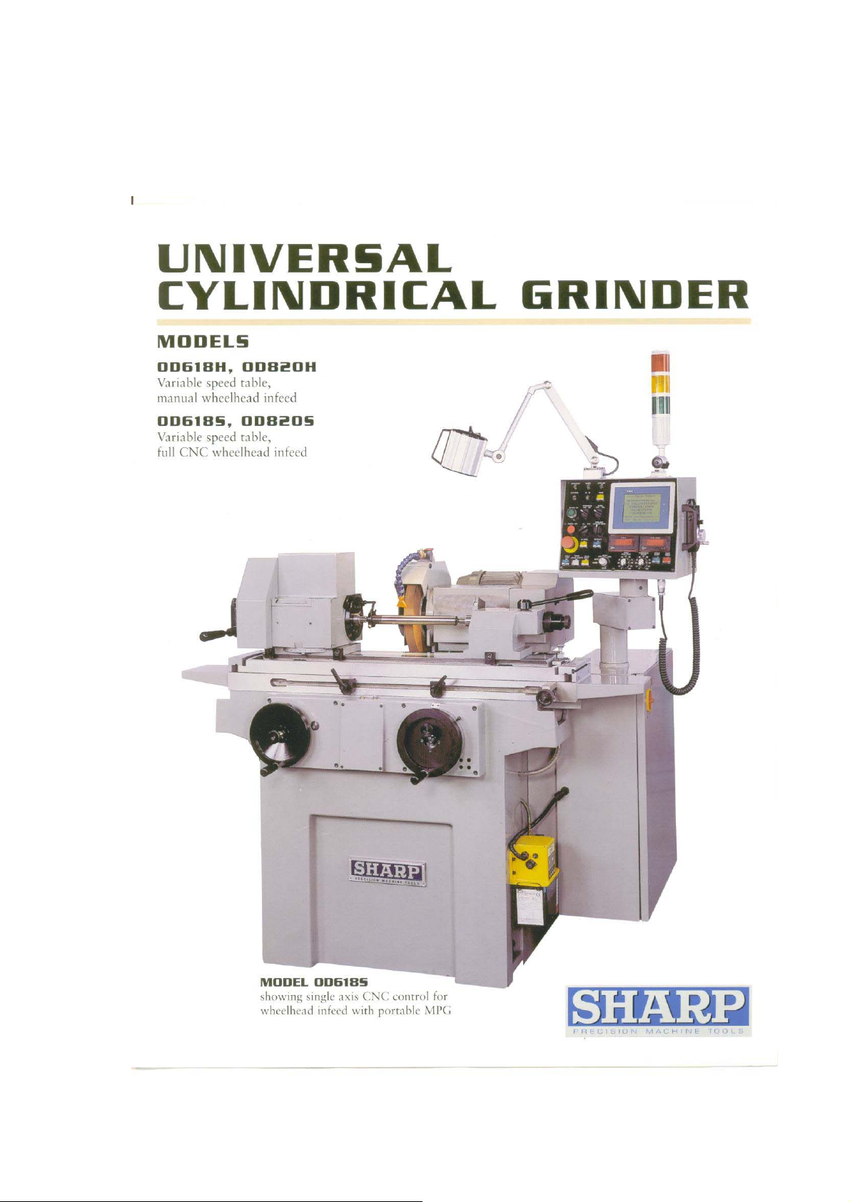
OD-618 S\H
OD-820 S\H
2
Page 2

Contents
z Operation Manual
z Electric Diagram
z Parts List
3
Page 3
Operation Manual
4
Page 4

Specification & Floor Space
Descrption Model
Swing over table
Distance between centers
Capacity
Wheelhead
Automatic
modles only
Grinding wheel
Internal
grinding
[Optional]
Workhead
Table
Maximum grinding diameter
Effective grinding diameter
Maximum load between centers 130 lbs 176 lbs
Hand feed travel
Feed of handwheel per division
Feed of handwheel per revolution
Swivel angle
Auto infeed range(by diameter)
Auto infeed passes ; control input
Auto infeed spark out
Diameter x Width x Bore
Wheel speed
Grinding bore range
Max. grinding length
Max. chucking length x diameter
Spindle speed 14000rpm 14000rpm
Internal grinding wheel motor 1/2 HP 1/2 HP
Spindle speed( Variable ) 0 ~ 500 rpm 0 ~ 500 rpm
Swivel angle
Taper of center 5C 5C
Travel speed( Variable ) 0 ~ 20 ipm 0 ~ 20 ipm
Feed of handwheel per revolution
Swivel angle
OD-618 H\S
8〞 8〞
18〞 20〞
6〞 8〞
5.25〞 / >6〞
4.2〞 6.3〞
0.0002〞 0.0002〞
0.1〞 0.1〞
+7° ; -13° +7° ; -13°
12〞 x 1〞 x 3〞 14〞 x 2〞 x 5〞
1960 rpm 1960 rpm
0.6〞 ~ 2.75〞 0.6〞 ~ 2.75〞
2.75〞 2.75〞
10.75〞 x 4.3〞 10.75〞 x 4.3〞
±45° ±45°
3/8〞 3/8〞
±8°
OD-820 H\S
±7°
Quill travel
Tailstock
Motors
General
*S Models controller: A-TECH AT-200A
Taper of center
Wheel spindle motor 2 HP 3 HP
Wo rkhead motor 1/4 HP 1/4 HP
Table travel motor
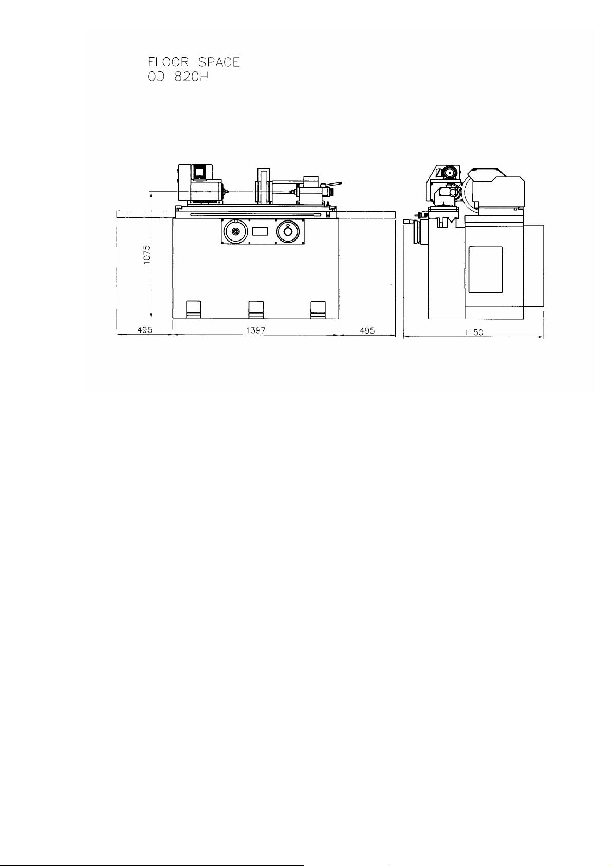
Floor space(L x D x H)
Net weight(approximately)
Servo Driver: Mitsubishi J2S
Servo Motor: Mitsubishi
Display : Hi_Tech LCD Human machine
Note :
change without notice
The contents of this brochure are reference only and are subject to
1〞 1〞
MT #2 MT #3
1/4 HP 1/4 HP
2300 lbs 3500 lbs
5
Page 5
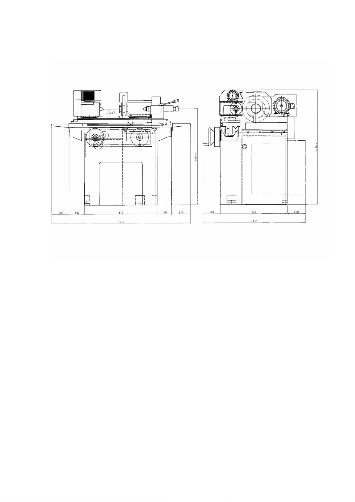
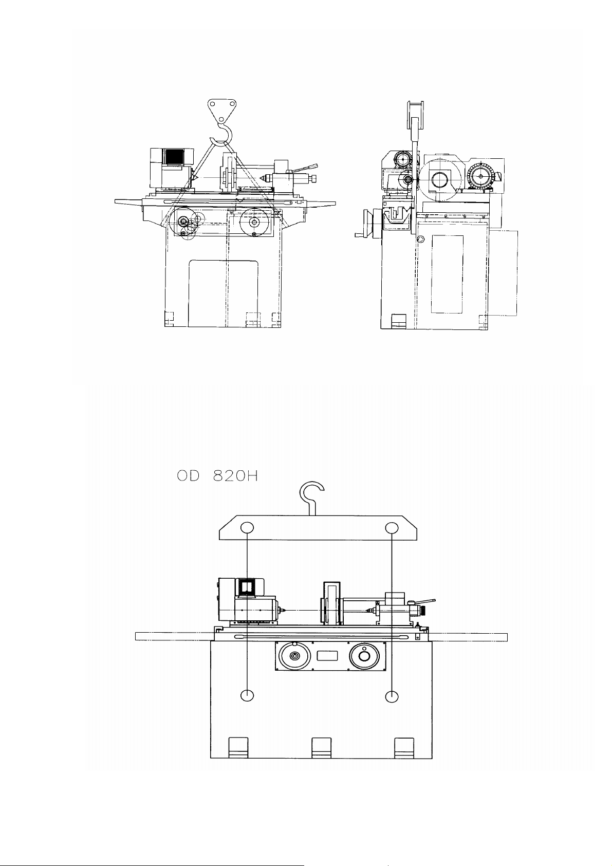
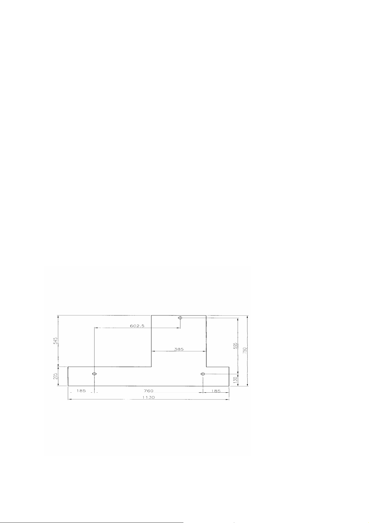
FLOOR SPACER OD-618H/S
6
Page 6
Transportation:
The table and wheelhead are fixed with red pressed plate before transportation to avoid
any damage .It must to remove all these red plates before operate machine
The wires outside the electrical cabinet and control are covered in flexible conduit for
protect from any damage ,and there is oil in auto-lubrication system
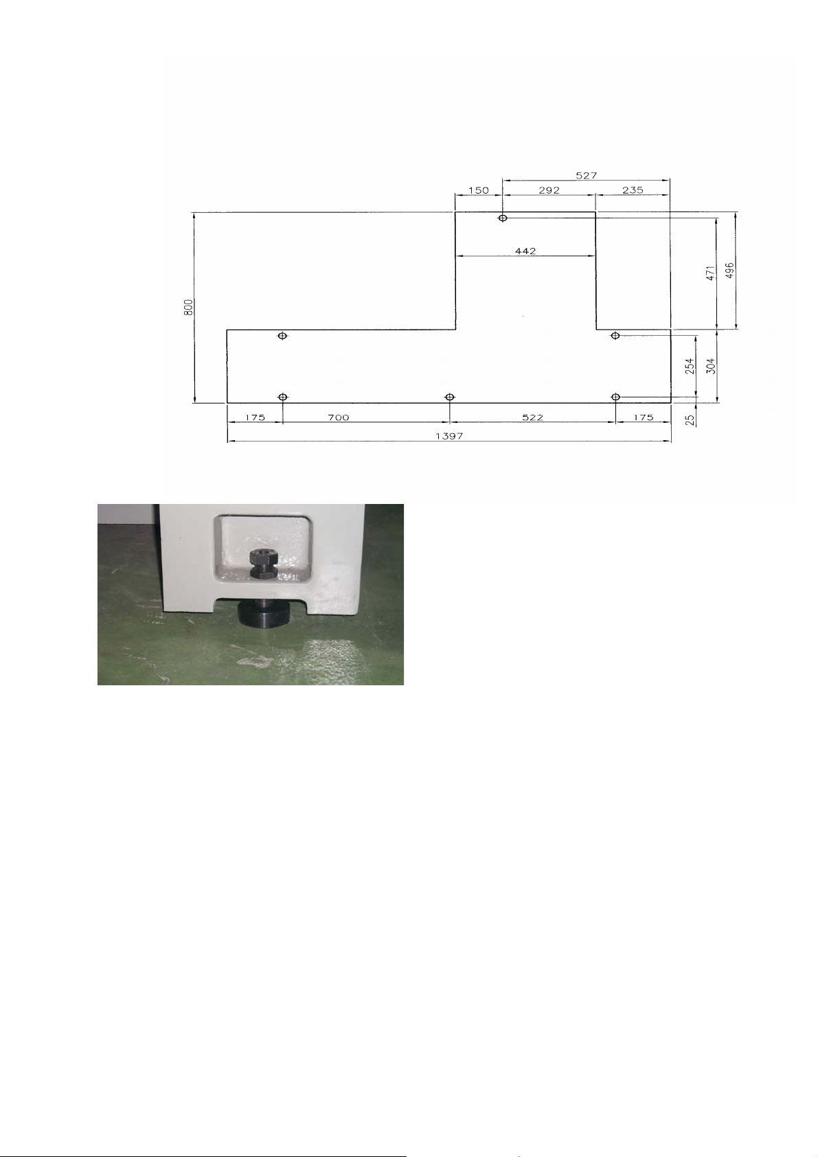
Before lifting the machine ,prepare an adequate cable .Hook the cable unto the eye-bolts
fixed at base .Please take a note of the following items while lift machine.
1. The cable must be capable of lifting weight more than 2 tons.
2. Place wooden wedge or rags between cable & machine to prevent the machine from
damage.
3. Lifting cable must be strong enough with diameter over 10mm.
4. Table must be truly fastened to avoid any slip during movement
Machine Transportation & Installation
7
Page 7
8
Page 8
Cleaning:
All sideways and ground surface are coated with anti-rust preventive before
delivery .Remove the coating with solvent agent prior to operation.
Installations:
While doing the installation ,special cares must be paid to the followings:
1. Never install the machine at an area where has direct sun light to maintain a
longer life ,preferable at an area has constant temperature.
2. Never install the machine at an area where is dusty ,not at an area next to
high-shocking machines ,such as ,air compressor ,press machine ,etc.
3. Machine is supplied with leveling and blocks as standard to facilitate and to avoid
any vibration.
Leveling:
It is essential to level the machine before operation . Please take a note of the following
items while leveling.
1. Prepare a level having the sensitivity of 0.02 mm/M( or 0.0002〞/ 10〞).
2. Clean the table surface before leveling .
3. Adjust the level as Figure indicates to place level.
4. After checking the table ,check torsion by traversing the table to left and right to
check if the table is distorted.
5. Check leveling which may be varied due to work load and others in 30 days after
installation .And check semiannually afterwards to retain grinding accuracy.
圖表 1
9
Page 9
10
Page 10

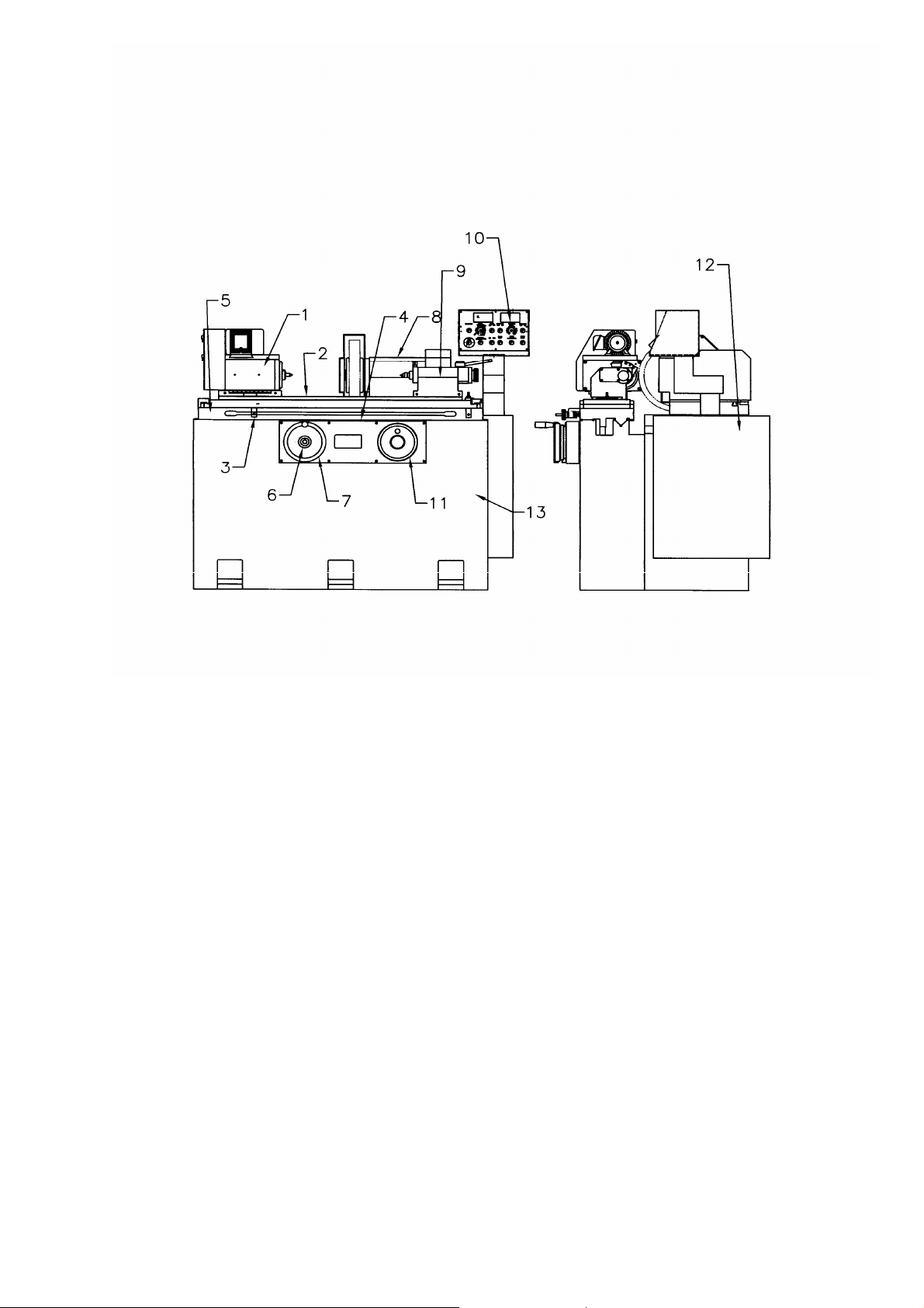
Description of Machine
ILLUSTRATIONS OF MACHINE
1. WORKHEAD
2. TOP TABLE SLIDE
3. TABLE TRAVEL LIMIT DOG
4. REVERSE LIMIT SWITCH
5. BOTTOM TABLE SLIDE
6. AUTO/MANUAL OPERATING KNOB
7. TABLE HANDWHEEL
8. WHEELHEAD
9. TAILSTOCK
10. CONTROL PANEL
11. WHEELHEAD HANDWHEEL
12. ELECTRICAL CABINET
13. BASE
11
Page 11
ILLUSTRATIONS OF CONTROL PANEL FOR OD 618H/820H
1. POWER “ON” BUTTON
2. I.D./O.D. SELECTION SWITCH
3. WHEEL “ON” SWITCH.
4. WHEEL”OFF” SWITCH
5. COOLANT ON “MANU.” POSITION
6. COOLANT OFF
7. COOLANT ON “AUTO” POSITION
8. TABLE RIGHT SIDE MOVEMENT BUTTON
9. T ABLE AUTO MOVEMENT BUTTON
10. TABLE MANU. MOVEMENT BUTTON
12
Page 12
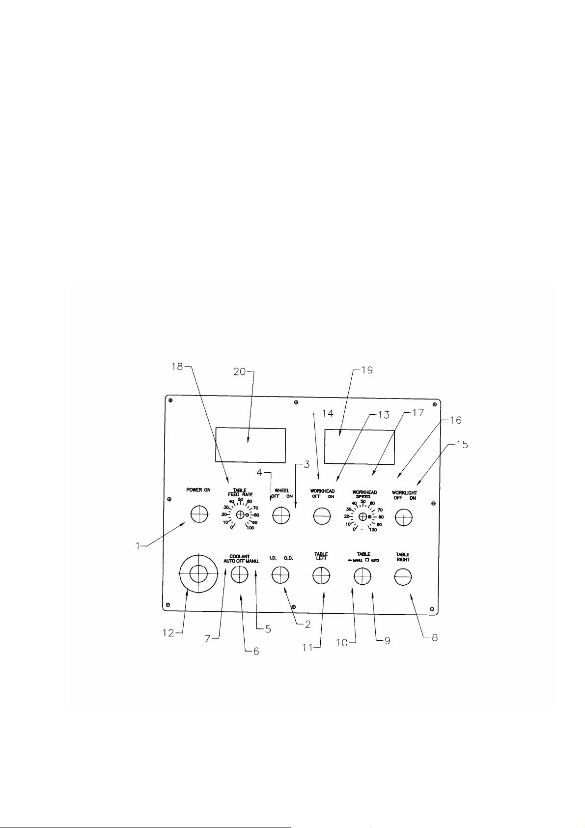
11. TABLE LEFT SIDE MOVEMENT BUTTON
12. EMERGENCY STOP SWITCH
13. WORKHEAD SWITCH “ON” POSITION
14. WORKHEAD SWITCH “OFF” POSITION
15. WORKLIGHT ON
16. WORKLIGHT OFF
17. WORKHEAD SPEED ADJUSTING KNOB
18. TABLE FEED RATE ADJUSTING KNOB
19. LED DISPLAY FOR WORKHEAD SPEED
20. LED DISPLAY FOR TABLE FEED RATE
13
Page 13

Electrical Power & Motors
Electrical equipment:
Rotation of motors:
Check the rotation of motors in details before operating the machine .
Wheelhead motor: The grinding wheel should rotate inward in the operator’s
Workhead motor: The tipped center should rotate inward in the operator’s
Coolant pump : Clockwise ( CW )
Table travel motor : Push up the button “TABLE AUTO MANUAL”,
then push the button “TABLE LEFT” or “TABLE
Note:
The rotation of motors are checked in the plant before delivery. In case any of the motors
run in opposite direction ,just switch any of the “R/S/T” cables in the electrical cabinet .
In case there are more than 2 motors run in opposite direction, a cable change from the
Individual motor connection is required.
Check the machine voltage with power source before connection. And check the
rotation of motors before operation.
direction.(Clockwise CW)
direction.(Clockwise CW)
RIGHT” .Check the table if move on the correct
direction.
14
Page 14

Lubrications System & Coolant System
Lubrication system :
Coolant system :
Recommended coolants :
material finish and wheel’s life .
There is an automatic lubrication supplied as standard for lubrication on all
slideways .The volume of the unit of 1 liter ( 2 liters for OD-820 Models)
The volume of coolant tank is of 72 liters . Just hook up the pipe to the coolant
nozzle before connecting power .
An appropriate coolant is essential for precision grinding ,and is resulted in the
A. Purpose of using coolant system.
a. Refrain material from temperature rise.
b. Flush off the grinding dust & peel-off grains.
c. Lubrication the material.
B. Category of coolant system.
a. Soluble coolant : Mainly with non-organic solution ,mostly suitable for
cast iron ,cast steel grindings .
1. Emulsion type
2. Soluble solution type
3. Solution type
b. Non-soluble coolant: A coolant with mineral oil in sulfuric
objects, suitable for lubrication.
15
Page 15
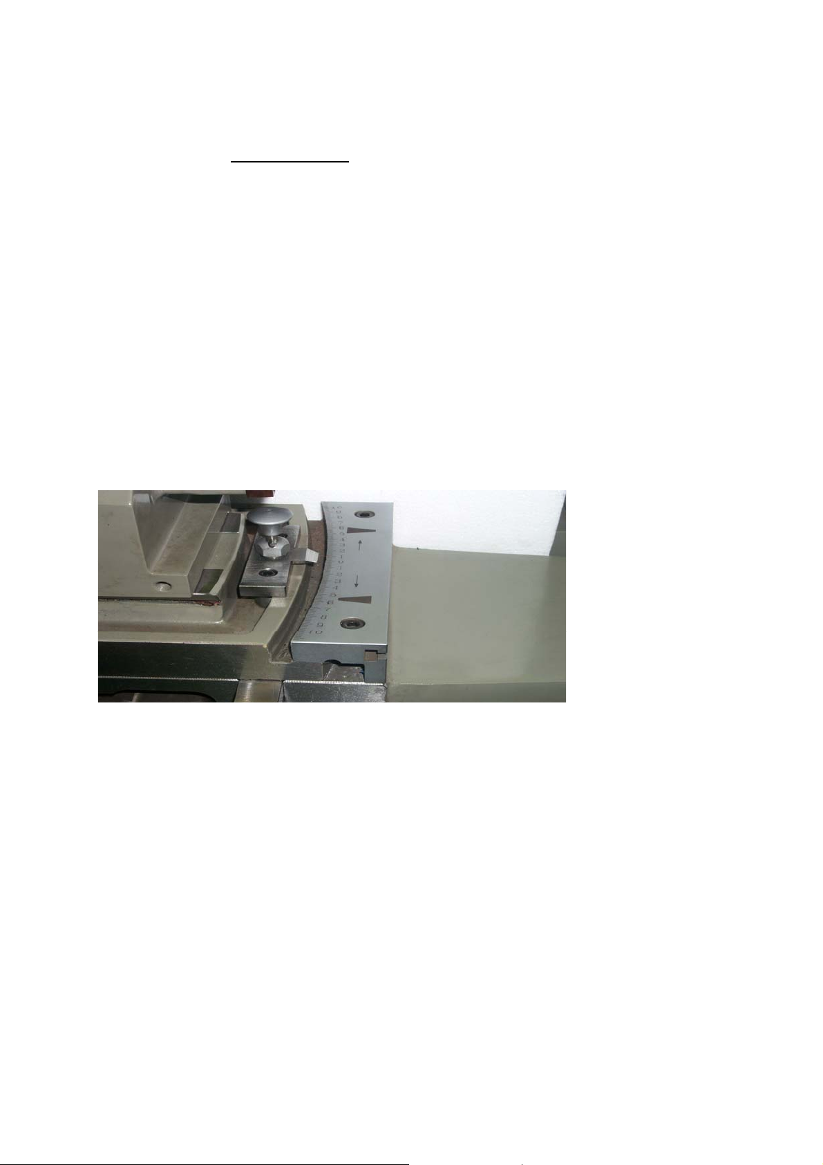
Table traverse and adjustment
The table can be driven both by manual and mechanical :
1. Manual traverse : Release the AUTO/MANUAL operating knob at the clutch
gear from the clutch unit. Swivel the handwheel to drive table manually.
2. Motorized auto drive : Adjust the table travel limit dogs to a desired
position. Tighten the AUTO/MANUAL operation knob at the table handwheel
to engage the clutch gear with the clutch unit .Push the “TABLE RIGHT” or
“TABLE LEFT” movement buttons to drive table automatically .The table’s
speed is variable that can be altered by Digital Variable Speed (DVS)System .
Adjustment of table inclination
The table consists of top & bottom slides in which the top slid is adjustable as foloows:
1. Release the two hex bolts at both table ends .
2. Pull up the knob .
3. Turn the adjusting knob in conjunction of the indicator to desired angle .
4. Tighten the two hex bolts at both table ends then begin grinding .
Table
16
Page 16
17
Page 17

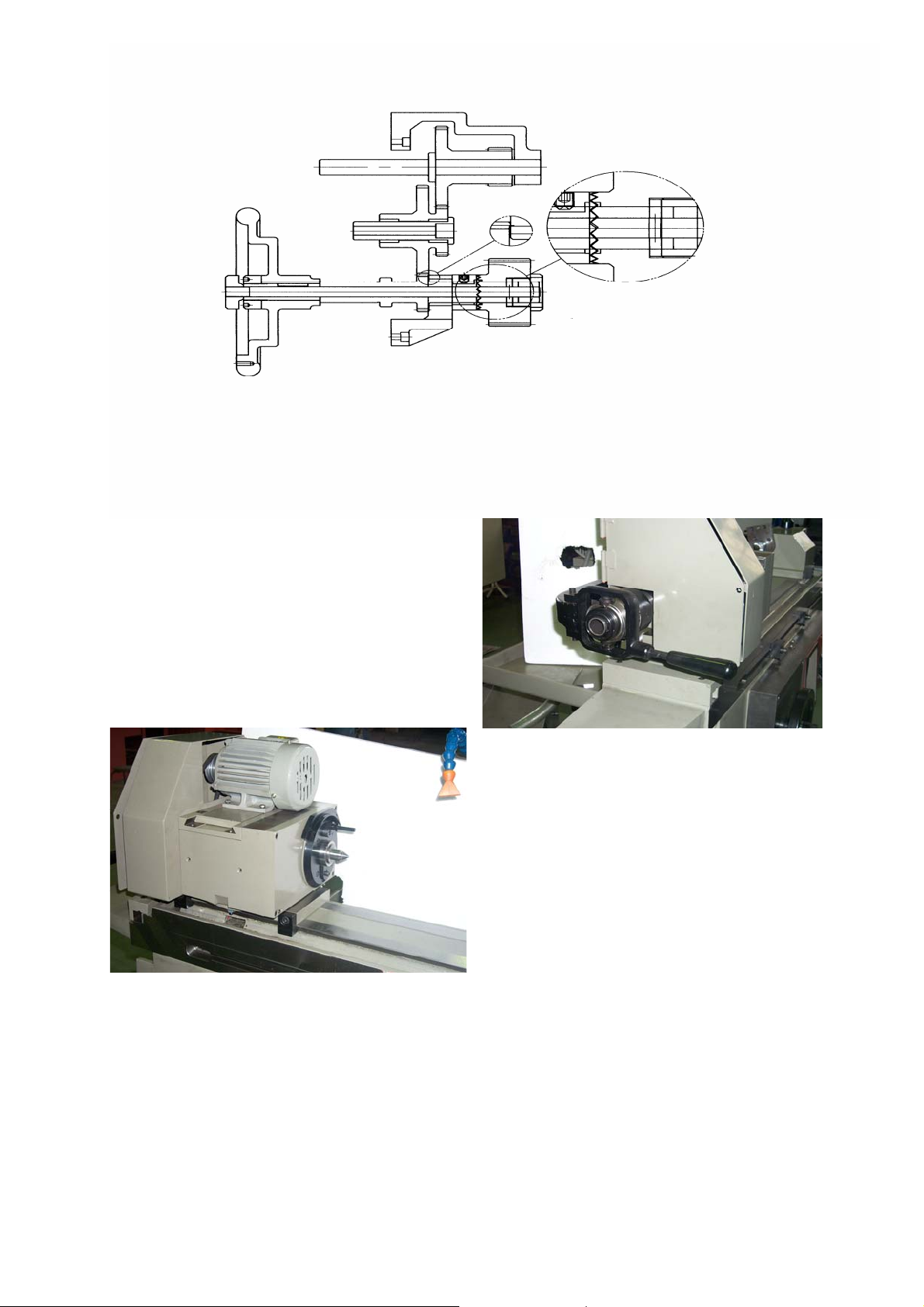
Workhead
Structure of workhead :
1. The workhead is furnished with 1/4 HP motor and is capable of variable speed that can be
altered by Digital Variable Speed ( DVS ) System.
2. Dead center and live center are available for supporting workpiece. Use a dead center for
external grinding. When using a 3-jaw chuck ,the spindle can be shift for a free rotation.
Adjustment of workhead :
1. Movement of workhead : Release the two fixed bolts at front of the unit to move the
workhead to desire position .Then clamp the two bolts .Clean the table surface before
moving is to be made .
2. Inclination of workhead: Release the two setting nuts at bottom of the unit to swivel the
workhead ±45° to an desire angle. Then clamp the nuts .
3. Alternation of dead center & live center: The spindle rotates when a chuck is used .Pull out
the plunger unit at back of the unit & press the clutch of driving plate into the groove of
spindle nose for free rotation. Star the procedures reversely while changing the live center to
dead center.
18
Page 18

5Ctype of workhead:
1. Clean inside of spindle nose and the collet .
2. Push in lock pin ( To engage lock pin ,turn spindle until pin lines up with the notch ) .
3. Disengage adjusting finger.
4. Place collet in the tube making sure the slot in the colet lines up with the pin in the spindle.
5. Apply light pressure to collet while turning “Shell Guard” making sure the threads
engage. Do not use force. If the collet does not go in smoothly, check for burs or damaged
threads.
6. Insert workpiece in the collet, move lever to the left or closed position and turn shell guard
toward the oprator until the collet seats.
7. Move lever to the right or released position and turn shell guard two notches toward the
oprator on the adjusting finger.
8. Move lever to the left or closed position and test the workpiece for correct tightness, if not
correct, make any adjustments needed and lock the adjusting finger .
19
Page 19

Tailstock
1. Move the tailstock in position according to workpiece length. Clean the table surface before
moving the tailstock to maintain accuracy.
2. Adjusting the tension of carbide tip center from the knob at rear of tailstock according to
workpiece length and forms. Turn the knob clockwise to increase tension whilst turn
counterclockwise to release. The workpiece may possibly be deflected or its center bore
expended in case the center tension is too great. To the contrary, workpiece would vibrate if
it is small.
3. Clean the center bore of workpiece and tailstock before clamping to ensure grinding
accuracy.
20
Page 20

Wheelhead
The wheelhead comprises of whellhead base ,rotary base ,saddle and saddle side, etc.That can
be driven both by manual and automatically and is inclinable for taper grinding.
Wheel spindle and bearings:
The wheelhead is the key part of the machine that adopts 4 pieces of precision angular contact
ball bearing providing a higher rigidity so as obtain a finer straightness and roundness.
Wheel spindle drive mechanism & adjustment
The wheel spindle is driven by a multiple V belt. A big tension may cause a poor surface finish
while a small tension cause vibration .Therefore it is imperative to keep an adequate belt tension
that can be adjusted through the bolts at back of motor.
Grinding Wheels
Selection of grinding wheels
A successful grinding is based on a qualified operator who knows well about the forms ,types and
property of grinding wheels and knows how to use them in different conditions .
Standard Marking System Chart
455x205x305 – WA – 80 – L - 5 - V – 2100
1. D x T
2. Abrasive symbol.
3. Grit size.
4. Grade.
5. S
6. Bond type.
7. Max. M/min (or M.P.M.)
1. 2. 3. 4. 5. 6. 7.
x H( mm ).
tructur
z D x T x H(mm)
The size of the grinding wheels .
z Abrasive:
Chemical composition of wheel grains used.
e.
:
21
Page 21

z Grit size:
Size of grain which will pass through a silk screen having that number of meshes to the
linear inch ( not square inch ) ,but will not pass through next smallest screen .Sizes smaller
than 220 are separated by hydraulic flotation and sedimentation or air classification .
z Grade:
Strength with which bond holds grains together ,or a measure of resistance which bond
exerts against a force tending to tear abrasive from wheel .It has nothing to do with abrasive
hardness as compared to a diamond .However ,a given wheel can be made to act relatively
harder or softer by varying work speed ,wheel speed ,depth of cut ,area of contact ,rate of
relative longitudinal movement of wheel and work .A given wheel and work .A given wheel
will act softer ( loses its grain readily ) if work speed (peripheral ) is increased or wheel
speed decreased .Decreasing area of contact makes a wheel act softer .Increasing infeed
( depth of cut ) or traverse rate will make a wheel act softer .The reverse of any of above will
make a given wheel act harder .
z Structure:
Is determined by porosity of wheel amount and size of air spaces between grains .( What
might be called swiss cheese effect where holes or pores are scientifically determined .) It is a
measure of closeness of adjacent grains ,or density .
z Bond type:
Material used for holding abrasive grains in wheel shape .Each grain is held in wheel by
coating of bond and joined to others by a network of bonding material .
z Max. M/min. ( or M.P.M. )
Max allowable M.P.M ( M/min ) .Keep the M.P.M. under the max M.P.M. can protect the
wheel from broken . ( R.P.M. = M.P.M. / πD )
Recommeneded Wheels for External Grindings
Parts Material
Wheel Specs
Wheel Outside Dia. ( ~ 355 mm )
Carbon Steel
Alloy Steel
Tool Steel
≦ HRC 25
> HRC 25
≦ HRC 55
> HRC 55
≦ HRC 60
> HRC 60
FA60MV
WA60MV
WA60LV
WA60KV
WA60KV
WA60JV
Stainless Steel WA60KV
Cast Iron C60JV
Special Cast Iron GC60IV
Chilled Cast Iron GC60IV
Malleable Cast Iron FA60MV
Brass C46JV ~ C36JV
Bronze 10A54LV ~ 10A36LV
22
Page 22

Aluminum Alloy C46JV ~ C36JV
Sintered Carbide GC80IV ~ GC60IV
Alnico WA46KV
Rubber C/GC 36 ~ 60 H ~ LV
Grinding Wheel :
1. Dimension of grinding wheel :
OD-618 S\H D x T x H = ∮12〞 x 1〞 x 3〞
OD-820 S\H D x T x H = ∮14〞 x 2〞 x 5〞
23
Page 23

圖表 2
24
Page 24

2. Assembly of grinding wheel:
a. Check the support surface, groove of wheel flange ,nut ,and screw holes for ant defects.
b. Put the flange into wheel bore slightly. The clearance between the wheel bore and flange
must be equal, namely, the wheel flange can not stay at one side
c. Screw up the flange cover with spanner.
d. After eight hours grinding service, screws should be checked for any looseness cause by
necessary to restore the original tension.
3. Installation of wheel:
25
Page 25

a. Clean the wheel bore and flange surface before mounting.
b. Put the assembled wheel onto spindle slightly .
c. Turn the nut C.C.W. to clamp the flange .
4. Extract of grinding wheel :
a. Remove the splash guard and open the wheel door .
b. Insert and turn wheel extractor C.W. to remove the wheel clamping nut .
c. Insert the wheel extractor into the wheel slightly .In no any condition ,it is strictly
prohibited to use a hammer or punch to take off the wheel forcibly .
Balance of Grinding Wheel :
1. Insert the flange into wheel tighten it .
2. Mount the wheel onto spindle switch on the spindle and dressing the wheel with
coolant .stop the coolant after dressing and let the wheel rotate for 10 minute or so to drop
the water off the wheel .
3. Dismantle the wheel set from spindle and put the balancing arbor thru flange bore ,and put
the wheel set on balance stand .Clean the flange bore and balance arbor tapered surface
before mounting .
4. Set the wheel for free rotation to locate its gravity center “S” and mark it with a chalk .
5. Put a balance weight at “S” position .Turn the wheel for 90 degree see in which side (S&G)
weight more .
6. Place 2 balance weight “K” at weightier side with same distance from “G” .
7. Turn the wheel for 90 degree see if the wheel is balanced .If not ,move the balance weight
“K” till the wheel is balance no matter in which position the wheel rotates .
Dressing of Grinding Wheel:
Installation of diamond dresser:
Put the diamond bit into the seat, front the tailstock body ,and tighten it .
Notes for wheel dressing;
a. A sufficient coolant is required whiled dressing the wheel .In the even of insufficient
coolant, the diamond bit will become carbonized due to high heat generated because
of friction. In this case, the life of diamond bit will be shortened and deteriorated if
keep using.
26
Page 26

b. The feed rate for each dressing should not be large as the diamond is an element of
hard and crispy, and is unbearable of impact .In order to prevent the diamond bit
from impact against grinding wheel, start the dressing from the middle of wheel
thru both ends.
c. A fixed moderate dressing rate: less than 5μm (0.0002) for a period of time and
cause a poor at times to regain a good and sharp dressing angle.
d. Formula of dressing speed :
F = D x N F : feed rate (mm /min )
2.5 x 1000 D: wheel grain size (μm)
N: wheel speeds (rpm)
Reference Table of Grinding Conditions :
A. Workpiece periphery speed range : UNIT :M.P.M(M/min)
R.P.M. = M.P.M. / πD (D = workpiece’s diameter ,M )
Type of Grinding Soft Steel
Coarse
Grinding
External
Grinding
Internal
Grinding
B. Feed rate per grinding : UNIT : mm
(1 mm = 0.039370〞≒ 0.04〞)
Type of Grinding Soft Steel
Fine
Grinding
Precision
Grinding
Fine
Grinding
10 ~ 20 15 ~ 20 15 ~ 20 10 ~ 15 25 ~ 30 25 ~ 40
6 ~ 15 6 ~ 16 6 ~ 16 6 ~ 15 14 ~ 20 18 ~ 30
5 ~ 10 5 ~ 10 5 ~ 10 5 ~ 10 5 ~ 10 5 ~ 10
10 ~ 40 16 ~ 50 6 ~ 40 20 ~ 50 40 ~ 60 40 ~ 70
Quenched
Steel
Tool Steel Cast Steel
Quenched
Steel
Tool Steel
Bronze
Steel
Stainless
Steel
Aluminum
Steel
Cast Steel
Plunge
Grinding
External
Grinding
Traverse
Grinding
Internal Grinding
Fine
Grinding
Coarse
Grinding
Fine
Grinding
Coarse
Grinding
Fine
Grinding
Coarse
Grinding
0.005 ~ 0.01 0.01 ~ 0.002 0.005 ~ 0.01 0.005 ~ 0.01 0.005 ~ 0.01
0.02 ~ 0.04 0.03 ~ 0.04 0.02 ~ 0.03 0.02 ~ 0.03 0.02 ~ 0.04
0.005 ~ 0.04 0.005 ~ 0.01 0.02 ~ 0.005 0.02 ~ 0.005 0.005 ~ 0.01
0.015 ~ 0.04 0.02 ~ 0.04 0.005 ~ 0.01 0.005 ~ 0.01 0.015 ~ 0.04
0.005 ~ 0.01 0.005 ~ 0.01 0.005 ~ 0.01 0.005 ~ 0.01 0.005 ~ 0.01
0.015 ~ 0.03 0.015 ~ 0.03 0.005 ~ 0.015 0.005 ~ 0.015 0.015 ~ 0.03
27
Page 27

Machine Alignment
Machine Alignment :
Check the machine accuracy as below in maintenance .
1. Alignment of table :
a. Place a dial gage on top of table and against dovetail surface of the upper table .
b. Turn the table handwheel to check if the zero-setting is obtained .
c. If not, adjustment can be made in reference of procedures as stated in Page 10 .
2. Alignment of workhead and tailstock :
a. Place a dial gage on top of table and a test bar into the spindle bore.
b. Direct the stylus to the test bar.
c. Turn the table handwheel to check if the zero-setting is obtained .
d. If not, adjust it in reference of procedures as stated in Page. 12 (adjustment of
workhead inclination) .
e. Test grind a bar of 300 mm long and measure the diameter at both ends see if it has the
same diameter. If not, realign the table.
28
Page 28

Safety Rule of Grinding Wheels
1. Carefully store grinding wheels in proper condition ,i.e. away from heat and humidity
sources .
2. Select correct wheel in accordance with grinding requirements.”Ring “ wheel and inspect
for cracks. Never use cracked wheel.
3. Strictly prohibit exceeding maximum safe operation speed established for wheel .
4. Use clean recessed matching flanges at least 1/3 wheel diameter .
5. Never alter hole in wheel or force wheel on spindle .
6. Wheel newly mounted or rarely used must run idle for at least 3 minutes before starting to
grind .
7. Under grinding ,carefully protect eyes and organ of breath .
29
Page 29

Electric Diagram
30
Page 30

31
Page 31

32
Page 32

33
Page 33

34
Page 34

35
Page 35

OD-820H\S
PARTS LIST
36
Page 36

37
Page 37

R
W
KEY PART NUMBER DESCRIPTION QUANTITY
1 GOD-61510 WHEELHEAD MOTOR COVE
2 EM03754P WHEELHEAD MOTOR 1
3 GOD-65280 MOTOR UPPER BASER 1
4 GOD-65220 MOTOR LOWER BASE 1
5 GOD-65210 SIDE COVER 1
6 SHS05012 SOCKET HEAD SCREW 2
7 GOD-65110 DRIVING PLATE 1
8 SHS-06012 SOCKET HEAD SCREW 1
9 GOD-65120 LOCATING PIN 1
10 SS05010 SET SCREW 2
11 SHS10016 SOCKET HEAD SCREW 2
12 GOD-65250 SLIDE FIXED BLOCK 2
13 GOD-61120 SLIDE BLOCK BASE 1
14 RHS-04016 REDIOUS HEAD SCREW 2
15 GOD-65350 ANGLE INDICATOR 1
16 RHS04006 REDIUS HEAD SCREW 2
17 GOD-65330 PLATE 1
18 GOD-67310 PULLY SIDE COVER BASE 1
19 GOD-67320 COVER 1
20 GOD-65160 HNOB 1
21 GOD-65322 MOTOR PULLY 1
22 BELT 1
23 DRK04020 KEY 4
24 SS05006 SET SCREW 1
25 GOD-65230 TAPER PLATE 1
26 SHS06014 SOCKET HEAD SCREW 1
27 HHS05016 H EX HEAD SC RE
28 SHS06016 SOCKET HEAD SCREW 4
1
4
38
Page 38

39
Page 39

KEY PART NUMBER DESCRIPTION QUANTITY
1 GOD- 65020 RIGHT COVER 1
2 SHS06025 SOCKET HEAD SCREW 4
3 OS-V110A OIL SEAL 1
4 GOD- 67290 DRIVEN PLATE 1
5 SHS08016 SOCKET HEAD SCREW 4
6 GOD-67270 P ULLEY 6
7 GOD- 61390 5C COLLET HOUSE 1
8 GOD- 86020 CARBIDE CENTER 1
9 SHS-06016 SOCKET HEAD SCREW 1
10 GOD- 65100 DRIVEN PLATE 1
11 GCT-11160 KEY SCREW 1
12 GOD- 67280 LOCKED NUT 1
13 BB-6911DDU BALL BEARING 2
14 VB-70A V STYLE BELT 1
15 RHS-08016 REDIOUS HEAD SCREW 1
16 W08B SPRING WASHER 1
17 GOD-65180 PULLY 1
18 VB-70A V STYLE BELT 1
19 RR-42 RETAINNG RING 2
20 BB-6004Z Z BALL BEARING 2
21 GOD- 65190 PULLY SHAFT 1
22 GOD- 65200 SLEEVE FOR SH AFT 1
23 SS08016 SET SCREW 2
24 GOD-65312 PULLY 1
25 VB BELT 1
26 GCT-14010 YOKE SHAFT 1
27 GCT-14130 HANDLE ROD 1
28 GCT-14110 KNOB 1
29 GCT-14060 O UTER RING 1
30 GCT-14140 BALL BEARING 1
31 GCT-14190 NUT 1
40
Page 40

KEY PART NUMBER DESCRIPTION QUANTITY
32 GCT-14210 BUSH BLOCK 1
33 SRR-32 SHAFT RETAINING RING 6
34 GOD-67100 COLLE T TU BE 1
35 GCT-14180 1
36 HN012F NUT 2
37 GCT-14040 SET SCR EW 2
38 GOD67330 LINK S H A FT 1
39 GCT14200 JAW 3
40 SP08100B PIN 3
41 SP0308B PIN 1
42 GCT-14100 NATCH 1
43 GCS2020 ADJUSTABLE NUT 1
44 GCT-14230 KEY PIN 1
45 GOD67250 S PINDLE 1
46 GOD67260 S PACE R 1
47 GCT14050 PIN 2
48 OS-V70A OIL SEAL 1
49 GCT KNO B 1
50 SP04016 PIN 1
51 GOD65290 SLEEVE 1
52 GCT- SPRING 1
53 GOD-65300 SHAFT 1
54 GOD-67240 WORKHEAD BASE 1
55 BB-7010CP4UL BALL BEARING 4
56 GOD-6 OUTER SPACE 1
57 GOD-6 INNER SPACE 1
41
Page 41

42
Page 42

18 PART NU M BER DESCR IPTION QUA NTITY
R
1 GOD62130 LOC K ED N U T 1
2 GOD62140A SP ACER 1
3 GOD61900 S PIND LE P U LLEY 1
4 GOD62060 INNER LO C KED N U T 1
5 GOD62050 OU TE R LO C KED N U T 1
6 GOD62030 REAR BEARING COVER 1
7 GOD62040 SP ACER 1
8 BB7011CP4UL BALL BEARING 4
9 GOD62021 SPINDLE SLEEVE 1
10 GOD62011 S PINDLE 1
11 GOD62040 S PACE R 1
12 GOD62070 S PACE R 1
13 GOD62040 S PACE R 1
14 GOD62080 FR O N T C O VER 1
15 SHS08020 SO CK ET H EA D S C R EW 6
16
17 GOD62090 F RO NT LOCKED N U T 1
18 GOD62160 WHEEL COVER BODY 1
19 GOD62100 WHE E L FLAN G E 1
20 GOD62110 FLANGE COVER 1
21 GOD62150 BALANCE BLOCK 3
22 BB03B BALL 3
23 GOD62120 N UT 1
24 GOD62140 S PACE R 1
25 GOD6222N LOCKED N U T 1
26 GOD62180 C OVE R 1
27 GOD62170 SWIVEL CO VE
1
28 GOD62210 FITTING BLOCK 1
29 GOD62270 S PACE R 1
30 SS08060 SET SCR EW 3
圖表 1
43
Page 43

44
Page 44

KEY PART NUMBER DESCRIPTION QUANTITY
1 SHS08020 SO C KET H E AD SC R E W 8
2 GOD61110 WHEEL B O DY C O VE R 1
3 GOD6108S WHEEL HEADSTOCK 1
4 IM024P 2HP4P MOTOR 1
5 GLS1880 SUPPO R T BLOC K 1
6 GOD61140 MOTOR SUPPOR T PLATE 1
7 SHS08035 SC O KET H E AD SC R E W 4
8 GOD61100 SUPPORT BLOCK BASE 1
9 SHS06045 SO C KET H E AD SC R E W 2
10 GOD68330 P LATE 1
11 GOD68340 PROTECT RUBBER 1
12 SHS06012 REDIUS HEAD SCREW 2
13 GOD61420 R EA R C O VER 1
14
15 SS06012 SET SCR EW 3
16 GOD61910 M O TO R P U LLEY 1
17 SRK08025 SINGLE REDIUS HEAD KEY 1
18 VB V TYLE B ELT 2
19 GOD61860 M O U N TING BO LT 2
20 GOD61850 M R TO R P U LLY C O VE R 1
21 GOD63080 BEARING BASE 2
22 SHS06020 SCO K ET H EA D S C R EW 4
23 GOD68240 S TO P B LO CK 1
24 GOD68250 ACTIVE STOP BLOCK 1
25 GOD65350 INDICATOR PLATE 1
26
27 GOD6108S WHEEL HEADSTOCK 1
28 GOD61090 WHEEL HEADSTOCK BASE 1
29 GOD61490 SUPPORT PLATE 1
30
圖表 2
45
Page 45

46
Page 46

KEY PART NUMBER DESCRIPTION QUANTITY
1 SHS06020 SO C KET H E AD SC R E W 2
2 GOD64130 BEARING SUPPORT 1
3 NBNA5904 NEDDLE BEARING 253723 1
4 GOD64050 C LUTC H G EA R 1
5 GOD64050 38T CLU TC H G EAR 1
6 SP05040 PIN 1
7 GOD64070 LOC K ED N U T 1
8
9 GOD64080 CLUTCH ROD 1
10 SS08080 SET SCR EW 1
11 GOD64100 53& 19T G E AR 1
12 NBF2016 NEDDLE BEARING F202016 3
13 SHS10100 SO CK ET H EA D S C R EW 1
14 GOD64090 SLEEVE 1
15 GOD64110 53T16T R AC K G EAR 1
16 GOD64140 GEAR BASE 1
17 GOD64120 G EAR S H A FT 1
18
19 SHS06020 SO CK ET H EA D S C R EW 2
20
21 FR80M10 KNO B 1
22 GOD64030S LEFT SIDE HAN D WHEE L 1
23 GOD64020 N UT 1
24 SRD06020 SINGLE REDIUS KEY 1
25 GOD64010 LO C KED NUT 1
26 GOD64020 LO C KED NUT
27 GOD6108S WHEEL HEADSTOCK 1
28 GOD61090 WHEEL HEADSTOCK BASE 1
29 GOD61490 SUPPORT PLATE 1
30
47
Page 47

48
Page 48

圖表 3
5
KEY PART NUMBER DESCRIPTION QUANTITY
1 GOD63140 76T G EA R 1
2 TLK3001822 CLAM P ING R ING 1pr.
3 WS010 FLAT WASHER 1
4 SHS10016 SO C KET H E AD SC R E W 1
5 GOD63120 19T PINION G EAR 1
6 DRK05030 DOUBLE REDIUS KEY 1
7 GOD63250 BU SH 1
8 GOD63110 GE AR SH A FT 1
9 BB6005ZZ BALL BEARING 4
10 GOD63080 BEARING HOUSE 2
11 SHS08016 SOCKET HEAD S C RE W 8
12 SDR05020 SINGEL REDIUS KEY 4
13 GOD63090 CONN EC TION BU SH 2
14 GOD63100 M IDDLE SHAFT 1
15 SS06006 SET SCR EW 4
16 CP04 CUPPER PLUG 4
17 GOD63070 WHEEL SHAFT 1
18 SHS08025 SOCKET HEAD S C RE W 1
19 GOD63410 LO C KED ROD 1
20 GOD63400 STO PPE R 1
21 HN08N NILON NUT 1
22 GOD63420 HANDLE STUD 1
23 GOD63430 S TO P ROD 1
24 GOD63450 N UT 2
25 SS05006 SET SCR EW 2
26 GOD63460 HA N D LE SH AF T 1
27 FR02
BLACK COLOR KNOB 1
28 GCT SCREW 1
29 GOD63040 WHEEL BASE 1
30
31 GOD63020 WHE EL 1
32 GOD63010 N UT 1
33 GOD63440 B OLT 1
49
Page 49

KEY PART NUMBER DESCRIPTION QUANTITY
34 GOD6306S SHAFT RING 1
35 GOD63030 WASHER 1
36 SHS08025 SOCKET HEAD SCREW 1
37 DDR05030 DOUBLE REDIUS KEY 1
38 SHS06030 SOCKET HEAD SCREW 4
39 FR80M10 KNOB 1
40
41 GOD63050 INDICATOR RING 1
42 GOD63190 LEAD SCREW 1
43 PN-020 PRECISION NUT 2
44 OSTC204207 OIL SEAL 4
45 GOD63170 BEARING COVER 2
46 BB6005ZZ BALL BEARING 4
47 GOD63180 BEARING HOUSE 2
48 GOD63210 SCREW NUT 1
49 GOD63220 NUT 1
50 GOD63230 SHIM 1
51 SHS08025 SOCKET HEAD SCREW 4
52 SHS05025 SOCKET HEAD SCREW 4
53 GOD63200 SCREW NUT 1
54 SHS08025 SOCKET HEAD SCREW 4
55 GOD63160 BUSH 1
56 GOD63150 BUSH 1
57 WS080 WASHER 1
58 SHS08025 SOCKET HEAD SCREW 1
50
Page 50

51
Page 51

KEY PART NUMBER DESCRIPTION QUANTITY
W
A
1 GOD66050 HANDLE BLOCK 1
2 GOD66010 BASE 1
3 SHS06014 SOCKET HEAD SCREW 2
4 SS08010 SET SCREW 1
5 DDNO-05 DIAMOND DRESSER 1
6 GOD66080 TAILSTOCK 1
7 GOD66070 ACTIVE PIN 1
8HN08 HEX. NUT 1
9 SS08010 SET SCREW 1
10
11 SHS06016 SOCKET HEAD SCREW 6
12 GOD65120 LOCKED BLOCK 2
13 SHS10016 SOCKET HEAD SCREW 2
14 KNOB 1
15 HANDLE 1
16 ADJUSTABLE HANDLE 1
17 GOD66040A CUPPER PLUG 1
18 GOD66040B CUPPER NUT 1
19 OSG35 OIL RING 1
20 SHS06030 SOCKET HEAD SCRE
4
21 CARBIDE CENTER 1
22 GOD66030 SHAFT 1
23 GOD66140 SEF SCREW 1
24 HN014F FINE NUT 1
25 GOD66120 SPRING 1
26 GOD66100 FIXED NUT 1
27 GOD66130
DJUSTMENT NUT 1
28
52
Page 52

53
Page 53

KEY PART NUMBER DESCRIPTION QUANTITY
1
2 OIL PAN 1
3 FITTING 1
4 RECYLE TANK 1
5 LUBRICATION UNIT 1
6 OIL TUBE 1
7 OIL LINE PLATE 1
8 OIL PLUG 1
9 FITTING 1
10 FITTING 1
54
 Loading...