

Page 1
Personal Computer
.
lllZ·OOrnJ
MONITOR
SB-1510
REFERENCE
MANUAL
SHARP
•
Page 2
J
SHARP
Personal
Computer
MZ-808
Monitor
SB-1510 Reference
Manual
·~.
january
1981
080231-150281
Printed
in
Japan
©SHARP
CORPORATION
Page 3
NOTICE
This manual
is
applicable
to
the
MONITOR
S8-1510
system software used with
the
SHARP MZ-
808
Personal Computer. The MZ-
808
general-purpose personal
computer
is
supported by system software which
is
filed
in
software packs (cassettes and diskettes).
All
system software
is
subject
to
revision
without
prior notice; therefore, you are
requested
to
pay special
attention
to
their file version numbers.
This
manual has been carefully prepared and checked
for
completeness, accuracy and
clarity. However,
in
the
event
that
you
should notice any errors or ambiguities, please feel
free
to
contact
your
local Sharp representative
for
clarification.
All
system software packs provided
for
the
MZ-808 are original products, and all rights
are reserved. No portion
of
any system software pack may be copied
without
approval
of
the
Sharp Corporation.
ii
Page 4
Introduction
This manual describes commands and subroutines
of
standard system software MONITOR
SB-151
0
for
the
Sharp MZ-80B and procedures
for
coding machine language programs and generating data.
MONITOR SB-151 0
is
part
of
the system software for the MZ-80B and it acts mainly as
the
moni-
tor
program for BASIC
SB-5
510, DISK BASIC SB-651 0 and Double Precision DISK BASIC SB-671 0.
Further, MONITOR SB-1510 can be used
as
a machine language
monitor
by
transferring system con-
trol
to
it. With this feature,
you
can
not
only code and debug machine language programs
but
also
generate system programs
of
your
own.
This manual includes all
MONITOR SB-151 0 assembly listings for reference.
iii
•.,
.
Page 5
Contents
Notice
....
......
....
.........
.
..............
..
...................
ii
Introduction . . . . . . . . . . . . . . . . . . . . . . . . . . . . . . . . . . . . . . . . .........
.....
iii
Chapter 1 MONITOR SB-1510 Commands and Subroutines
................
1
1.1
Function
of
the
monitor
program . . . . . . . . . . . . . . . . . . . . . . . . . . . . . . . . 2
1.2 Using
monitor
commands . . . . . . . . . . . . . . . . . . . . . . . . . . . . . . . . . . . . . . . 4
1.2.1
1.2.2
1.2.3
1.2.4
..
;.
1.2.5
1.2.6
M command
........
.....
.............................
. 4
D command
........................
.... .-......
.
.......
7
J command
...
...
....
. . .
...............................
9
S command
V command
L command
.......
.........
...
.....
............
.
....
. 10
.......
.
..................................
12
13
1.3 Monitor Subroutines. . . . . . . . . . . . . . . . . . . . . . . . . . . . . . . . . . . . . . . . . .
15
Appendix
.......................................................
21
A.l Mnemonic Codes and Corresponding Object Codes . . . . . . . . . . . . . . . . . . 22
(Mnemonic codes are arranged in alphabetic order.)
A.2
Object Codes and Corresponding Mnemonic Codes
...............
...
32
(Object codes are arranged in hexadecimal order.)
A.3
MONITOR SB-1510 Assembly Listing ..............
.....
..... ..
. 42
iv
Page 6
Chapter 1
MONITOR
SB-1510 Commands and Subroutines
This chapter describes six commands executed
at
the
monitor
command level and
monitor
sub-
routines enables the user to generate, execute and/or
file
a simple machine language program;
that
is,
to operate the MZ-80B at the
CPU
level. Machine language programs generated can be linked with
other BASIC programs with the USR function
of
the BASIC language.
I
Page 7
2
1.1
Function
of
the monitor program
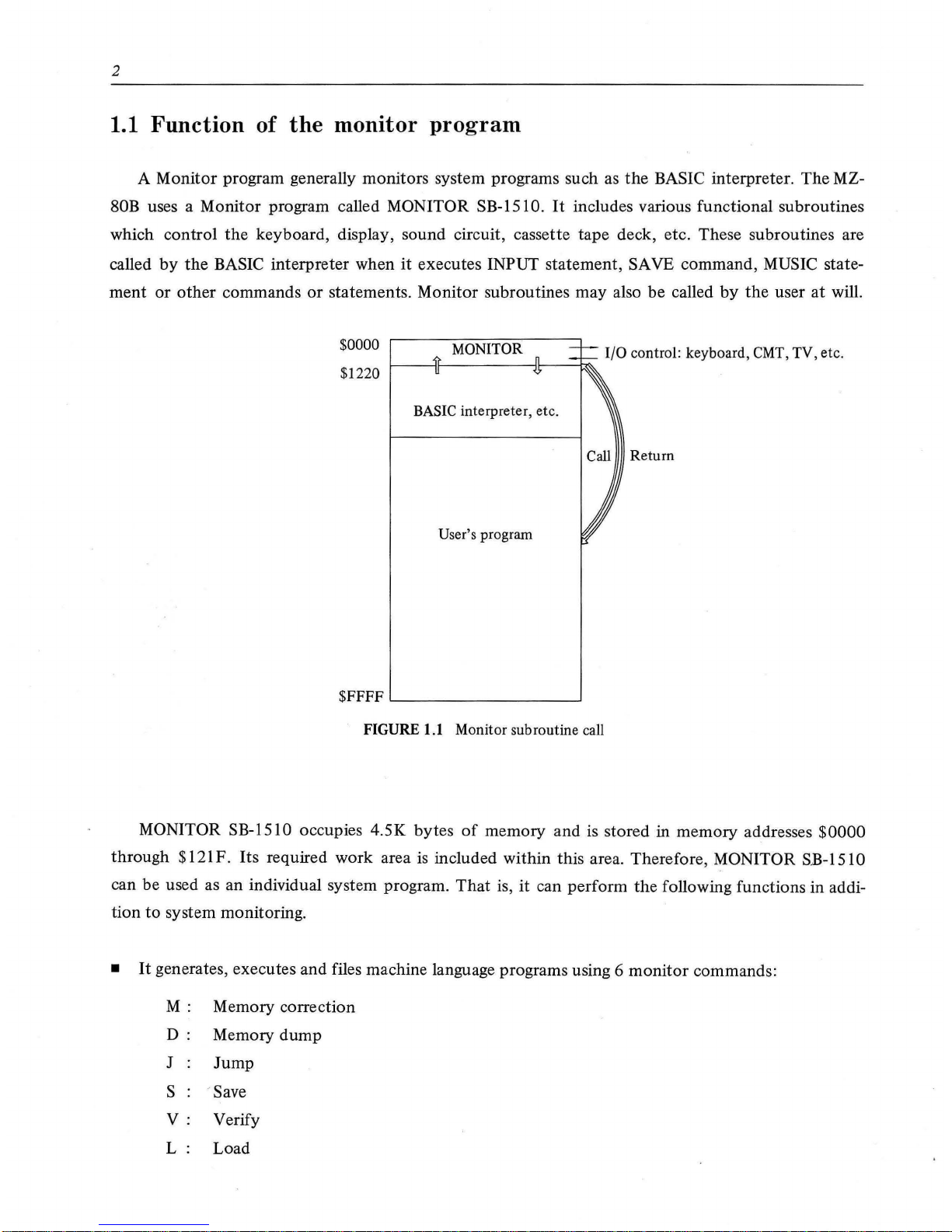
A Monitor program generally monitors system programs such as
the
BASIC interpreter.
The
MZ-
80B
uses a Monitor program called MONITOR SB-1510.
It
includes various functional subroutines
which control
the
keyboard, display, sound circuit, cassette tape deck, etc. These subroutines are
called
by
the
BASIC interpreter when
it
executes INPUT statement, SAVE command, MUSIC state-
ment
or
other
commands
or
statements. Monitor subroutines may also be called
by
the
user
at
will.
$0000
$1220
MONITOR
BASIC
interpreter, etc.
User's program
$FFFF
...._
_______
__,
FIGURE 1.1 Monitor subroutine call
1/0
control: keyboard, CMT, TV, etc.
Return
MONITOR SB-1510 occupies 4.5K bytes
of
memory
and
is stored in memory addresses
$0000
through $121 F. Its required work area is included within this area. Therefore, MONITOR SB-151 0
can be used as an individual system program.
That
is, it can perform the following functions in addi-
tion
to
system monitoring.
•
It
generates, executes and files machine language programs using 6
monitor
commands:
M:
Memory correction
D:
Memory
dump
J
Jump
s
-save
V:
Verify
L:
Load
Page 8
3
• Since MONITOR SB-1510
is
stored in RAM, its contents may be varied with commands.
For
example, the contents
of
$0000-
$0038 and $0066, which are called when processing an inter-
rupt, can be changed at will
or
the
function
of
a monitor subroutine can be modified.
Programs may be freely written
on
cassette tape,
so
a machine language program including MONI-
TOR SB-1510 can
be
filed for future use. See
the
assembly listing for MONITOR SB-1510 in Ap-
pendix A.3.
To use monitor commands, system control must be transferred
to
the Monitor from the BASIC
interpreter
or
other
system program.
• To transfer system control from the BASIC interpreter
to
the
Monitor, execute a
MON
command.
• To transfer system control from
the
Assembler
or
Linkert
to
the Monitor, execute a ! command.
•
To
transfer system control from
the
PASCAL
interpretertt
to
the Monitor, execute
an
editor _
command,
Q/.
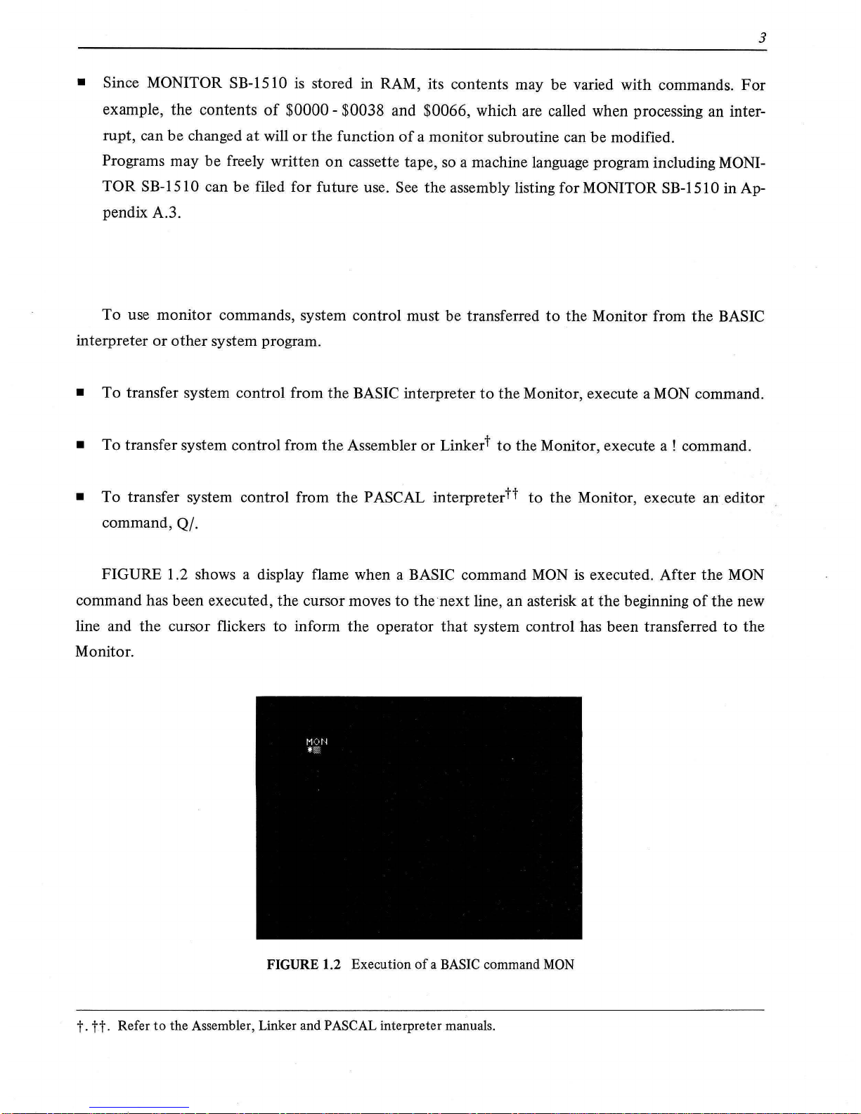
FIGURE 1.2 shows a display flame when a BASIC command
MON
is
executed. After the
MON
command has been executed, the cursor moves to the next line, an asterisk at the beginning
of
the new
line and the cursor flickers to inform the operator
that
system control has been transferred
to
the
Monitor.
FIGURE
1.2 Execution
of a BASIC
command
MON
t.
tt.
Refer
to
the Assembler, Linker and PASCAL interpreter manuals.
Page 9
4
1.2
Using
monitor commands
General conventions for use
of
Monitor commands are as follows:
• Commands and data are
input
from
the
keyboard with
the
I CR ] key pressed
to
conclude
the
entry.
• Data display and
input
are in hexadecimal. One
byte
of
data consists
of
two
hexadecimal digits
and an address consists
of
four hexadecimal digits.
• When
the
number
of
characters
input
firm
the
keyboard exceeds
the
number
the
required
by
the
Monitor program,
the
excess are ignored.
•
To
cancel execution
of
a command, press
the
I BREAK] key.
• Every command can access any memory location, allowing a wide range
of
applications,
but
spe-
ci~l
care must
be
taken
not
to
destroy required data
or
a program.
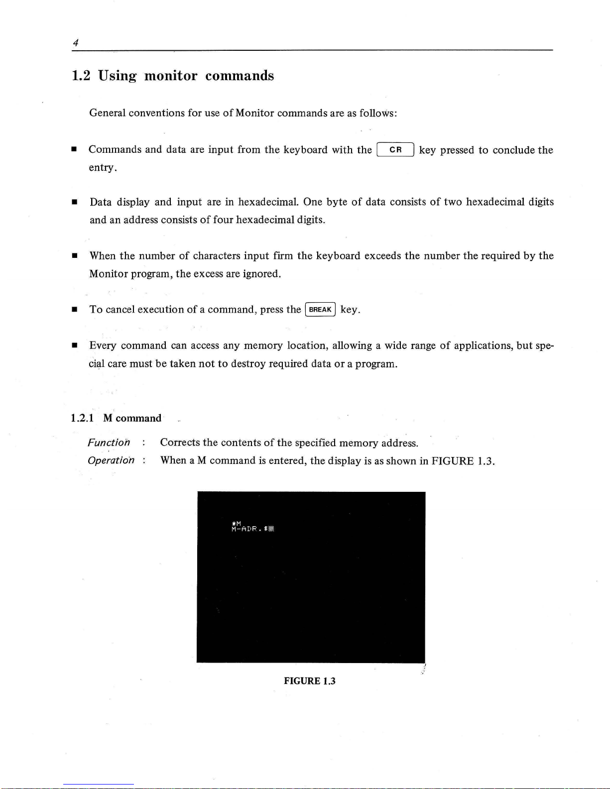
1.2.1 M command·
Function
Operation
Corrects
the
contents
of
the
specified memory address.
When
aM
command is entered,
the
display is as shown in FIGURE 1.3.
FIGURE 1.3
Page 10

5
In
this case,
the
Monitor requests
the
operator
to
enter
the
address
at
which mem-
ory correction
is
to
start.
For
example, let memory correction start
at
memory address $70AO.
Enter
70AO
from
the
keyboard,
then
press
the
[
CR
] key. The display is as shown in FIGURE
1.4.
FIGURE
1.4
The
monitor
program displays
the
contents, $00,
of
memory address $70AO and
requests
the
operator
to
determine whether or
not
the
contents
of$
70AO
are
to
be
corrected.
To
correct them,
enter
two hexadecimal digits, from
of
00
to
FF,
at
the
cursor position from
the
keyboard.
For
example,
to
change
the
contents
of
$70AO
from $00
to
$C9 (operation code
of
the
RET command),
enter
"C9",
then
press
the
[
CR
] key.
The
monitor
program
then
corrects
the
contents
of
the
memory address and
the
display is as shown in FIGURE 1.5.
FIGURE
1.5
Page 11
6
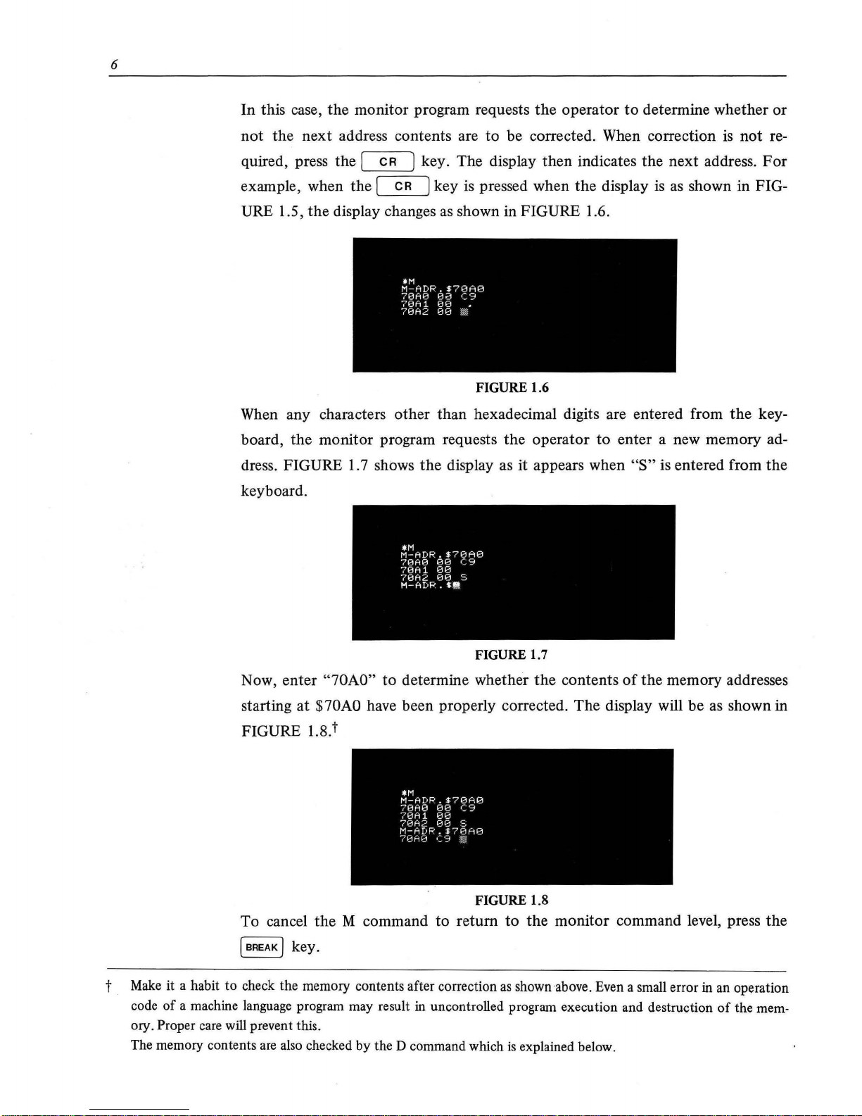
In this case, the monitor program requests the operator
to
determine whether
or
not
the next address contents are to be corrected. When correction
is
not re-
quired, press the [
CR
J key. The display then indicates
the
next address.
For
example, when the [
CR
] key
is
pressed when
the
display
is
as
shown in FIG-
URE 1.5,
the
display changes
as
shown in FIGURE 1.6.
FIGURE 1.6
When any characters other than hexadecimal digits are entered from
the
key-
board,
the
monitor program requests
the
operator
to
enter a new memory ad-
dress. FIGURE
1.
7 shows
the
display as it appears when
"S"
is
entered from the
keyboard.
FIGURE 1.7
Now, enter "70AO" to determine whether
the
contents
of
the memory addresses
starting at $
70AO
have been properly corrected. The display will be
as
shown in
FIGURE 1.8.t
FIGURE 1.8
To
cancel
the
M command
to
return
to
the
monitor command level, press the
( BREAK ) key.
t
Make
it a habit to check the memory contents after correction
as
shown above. Even a small error
in
an operation
code
of
a machine language program may result in uncontrolled program execution and destruction
of
the mem-
ory.
Proper care will prevent this.
The memory contents are also checked
by
the D command which
is
explained below.
Page 12
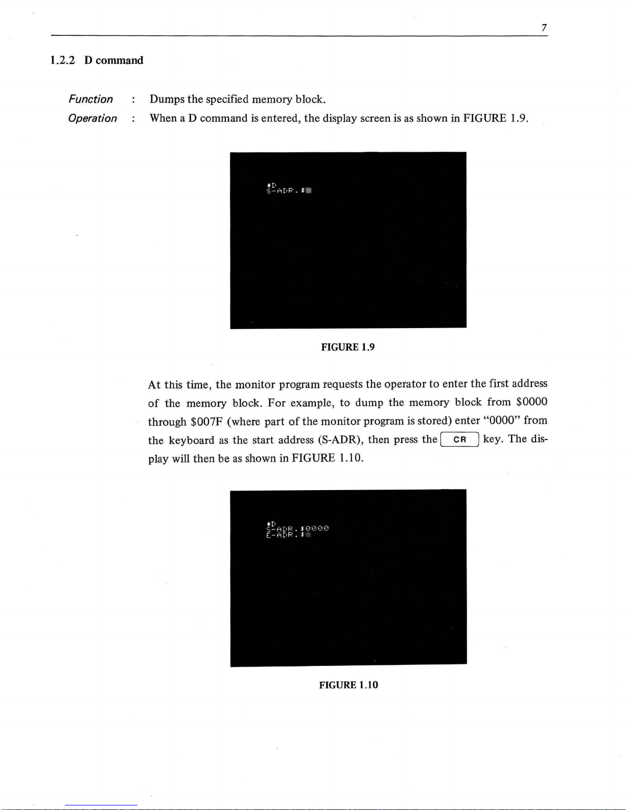
1.2.2 D command
Function
Operation
7
Dumps
the
specified memory block.
When
aD
command is entered,
the
display screen is as shown in FIGURE 1.9.
FIGURE 1.9
At
this time,
the
monitor
program requests
the
operator
to
enter
the
first address
of
the
memory block.
For
example,
to
dump
the
memory block from $0000
through
$007F
(where
part
of
the
monitor program is stored) enter
"0000"
from
the
keyboard
as
the
start address (S-ADR),
then
press
the
[
CR
J key. The dis-
play will
then
be
as shown in FIGURE
1.1
0.
FIGURE 1.10
Page 13
8
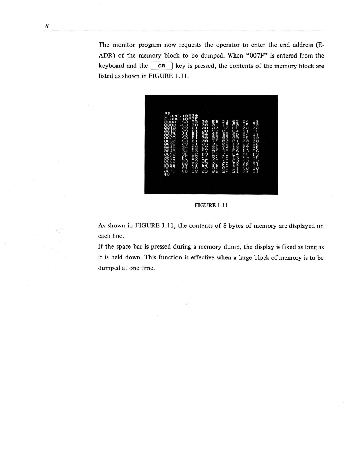
The monitor program now requests
the
operator
to
enter
the
end address (E-
ADR)
of
the
memory block
to
be dumped. When
"007F"
is entered from
the
keyboard and the I
CR
] key is pressed,
the
contents
of
the
memory block are
listed as shown in FIGURE 1.11.
•D
5-ADR
Hl880
E-ADP
$087F
1313130
(.3
3B
08
EB
D
1
05
04
1
:;:
01308
,e;3
00
00
8 1
18
08
1F
~30
131310
C3
B 1
88
08
D0
FF
88
~'711:-1
13018
•:3
B 1
00
C8
83
84
11
FF
RH~H
(;3
B 1
88
38
38
8[.
04
1
:;·
~~~~
·:3
B 1
00
80 80
88
HE
10
(.3
B 1
00
?F
80
01
~~n3
~::,
1:1
1111
=::=:
a
'='1
0D
3E
82
[•?. E
:::
~:[
~~~ ~~!
~
~~
(.:::
E7
3E
74
Io?.
E7
:::E
E:4
Io?.
E7
AF
[.3
EE
[•
:::
E~.
~-=-11:1
C'"
1:-1
:;:E
n
[•::::
E5
D3
E4
HF
[•
=:
~~,~~1
~
:~:
E5
E4
3E
CF
[o
:::
~·~
HF
oor::.o
[•
:::
?.E
CF
1C•
~1-=:
-
:
n
1:11:1~,
:=:
1:11:1
a
EE:
?.E
FF
f·
~:
~
E:
~~,~~171~1
'~'I
~B
(;)
E:
~3Et
3 1
I
1:1
10
007:=:
[!
(16
2F
2 1
~~~1
1 1
.,,
FIGURE 1.11
As shown in FIGURE 1.11,
the
contents
of
8 bytes
of
memory are displayed
on
each line.
If
the
space bar
is
pressed during a memory dump,
the
display is fixed as long as
it
is
held down. This function
is
effective when a large block
of
memory is
to
be
dumped
at
one time.
Page 14
1.2.3 J command
Function
Operation
9
Transfers system control
to
the specified address,
that
is, loads
the
specified ad-
dress in the program counter
of
the
CPU.
When a J command is entered, the display
is
as shown in FIGURE 1.12.
FIGURE 1.12
At this time,
the
monitor program requests the operator
to
enter the address
to
which system control
is
to be transferred.
Enter
a 4-digit hexadecimal address
from
the
keyboard and press the [
CR
) key. System control
is
then transferred
to
the machine language program starting at the specified address.
This command
is
used to invoke a machine language program. Before executing a
machine language program, carefully check
the
program. Careless execution
of
a
machine language program may result in a serious error.t This command
is
also
used
to
restart
the
BASIC interpreter
or
other system program
if
it has
not
been
destroyed. There are two methods
of
restarting the system program: warm start
and cold start. With a warm start, previous system data (that is, data which was
stored in the system work area at the end
of
the last execution
of
the system pro-
gram) are
not
erased. With a cold start, previous system data are ignored just
as
during an initial start with the IPL. The start addresses
of
the BASIC interpreter
are
as
follows:
Warm
start address= $1280
Cold start address = $1220
t The hardware
will
not be damaged, but a
ftle
protected tape may be overwritten with something
else
or the pro·
gram in
RAM
may
be
destroyed.
The
RST 7 instruction (OBJ Code: $FF)
is
used to stop machine language program execution.
When
the
RST
7
instruction
is
encountered, system control
is
transferred to the monitor program to wait for the next command.
At the
same
time, the contents
of
registers AF,
BC,
DE,
HL
and
P~
are displayed on the CRT screen in sequence
in
4 digit hexadecimal notation. The
PC
register contains the address where the RST 7 instruction
is
stored.
It
is
recommended that RST 7 instructions be placed in appropriate program locations for
ease
of
debugging. To
continue program execution, execute the J command. (The contents
of
the
PC
register which were pushed
to
the
stack
by
the RST 7 instruction
have
been popped from the stack by the break routine. Therefore, no RET instruc-
tion can be executed.)
Page 15
10
1.2.4 S command
Function
Operation
Saves the contents
of
the specified memory block
on
cassette
tape
with
the
specified file name assigned.
When
aS
command
is
entered,
the
display is
as
shown below.
*S
FILENAME:
c::::l
The
monitor
requests
the
operator
to
specify file name.
Enter
an appropriate file
name
of
16 characters
or
less from
the
keyboard
and
press the [
CR
] key.
For
example, when "ABRACADABRA" is specified,
the
display is as shown below.t
*S
FILENAME: ABRACADABRA
S-ADR.$
c::ll
After the file name has been specified,
the
monitor
requests the operator
to
specify the memory block
to
be saved.
Enter
the
start
and end addresses in
the
manner
described
in
the
D command explanation. Any start and end addresses
of
the
installed memory can be specified; however,
if
the
monitor
area is saved, a file
which cannot be coded
is
generated
on
the
cassette tape. This
is
because
the
moni-
tor
saves itself, so check sum codes necessarily mismatch.
t
If
the
~
key
is
pressed without specifying a
file
name, a nameless file
is
generated. This
is
not
desirable.
It
is
strongly recommended that
flle
names be specified for all significant files.
Page 16
11
For
example,
to
save
the
memory block from $6000
to
$60A3 with
the
file name
"ABRACADABRA" assigned,
enter
"6000"
and press the I CR ] key,
then
enter
"60A3"
and press
the
I
CR
] key. The display is
as
shown below.
*S
FILENAME: ABRACADABRA
S-ADR.$6000
E-ADR.$60A3
1-ADR.$
~
The monitor now requests the operator
to
enter a
jump
address.
If
a
jump
address
is
specified, system control will be transferred
to
this address after loading when
the file
is
later loaded
by
a L command. This feature
is
useful when
the
file
is
an
individual machine language program file.
When
the
file
is
a data file
or
program file which
is
linked with the BASIC inter-
preter,
the
jump
address
is
not
specified.t
In
this case,
the
monitor
will retain
system control after file loading.
For
example, when file "ABRACADABRA" includes a program with a starting
address
of
$6050,
enter
"6050"
from the keyboard as shown below.
J-ADR.$6050
After
the
I
CR
] key
is
pressed,
the
file will be saved. When no cassette
is
in-
stalled in
the
cassette tape deck,
the
cassette tape cover will open and
the
message
"SET TAPE" will appear
on
the
screen
if
aS
command is attempted. When a file
protected tape
is
loaded,
the
message "WRITE PROTECT" will appear
on
the
screen
if
aS
command
is
attempted.
t Press the
~
key without entering the address.
Page 17
12
1.2.5 V command
Function
Operation
Checks to confirm that data in a cassette tape file matches the original data in the
memory block from which it was saved.
When a V command
is
entered, the display
is
as
shown below.
*V
FILENAME:§
The monitor requests the operator
to
specify the file name
to
be verified.
For
example, when file "ABRACADABRA"
is
to
be verified, enter "ABRACADA-
BRA" from the ·keyboard
as
shown below. Note
that
the cassette tape must first
be rewound.
*V
FILENAME: ABRACADABRA
When the
I
CR
r key
is
pressed, verification
is
performed automatically. The
memory block with which the specified file
is
compared is indicated by informa-
tion recorded when
the
file was saved with the S command.
If
the
file name
is
not specified,
the
first cassette tape file data encountered will
be verified.
When the file data
is
the same
as
data in the memory block,
"OK"
is
displayed;
when it differs,
"ERROR"
is
displayed.
Although cassette deck read/write operation
is
highly reliable, it
is
recommended
that
a habit be made
of
verifying data every time a file
is
saved.
Page 18
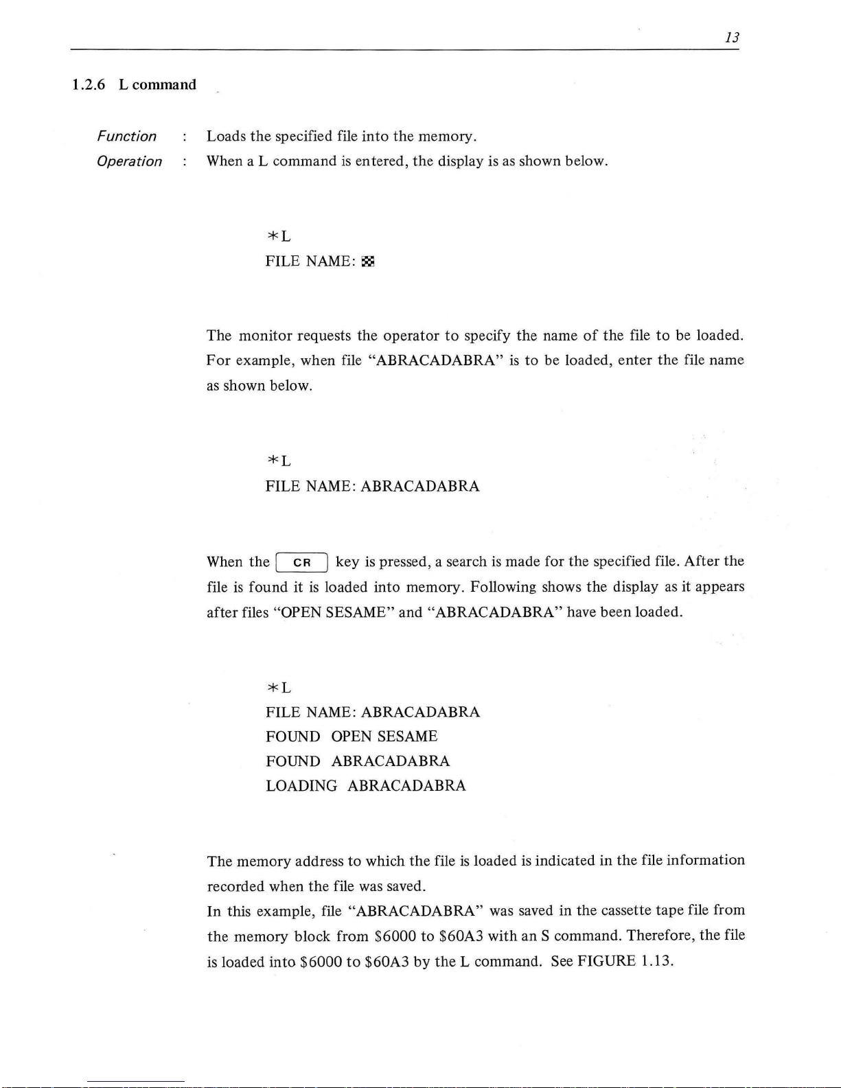
1.2.6 L command
Function
Operation
13
Loads
the
specified file
into
the memory.
When a L command
is
entered,
the
display is
as
shown below.
*L
FILE
NAME:~
The
monitor
requests the
operator
to
specify
the
name
of
the file
to
be loaded.
For
example, when file "ABRACADABRA"
is
to
be loaded,
enter
the
file name
as
shown below.
*L
FILE
NAME: ABRACADABRA
When
the
[
CR
] key
is
pressed, a search
is
made for the specified file.
After
the
file
is
found it
is
loaded
into
memory. Following shows
the
display as it appears
after files
"OPEN SESAME" and "ABRACADABRA" have been loaded.
*L
FILE
NAME: ABRACADABRA
FOUND OPEN SESAME
FOUND ABRACADABRA
LOADING ABRACADABRA
The memory address to which
the
file
is
loaded
is
indicated in the file information
recorded when the file was saved.
In this example, file
"ABRACADABRA" was saved in the cassette tape file from
the
memory block from $6000
to
$60A3
with
an
S command. Therefore,
the
file
is loaded
into
$6000
to
$60A3
by
the
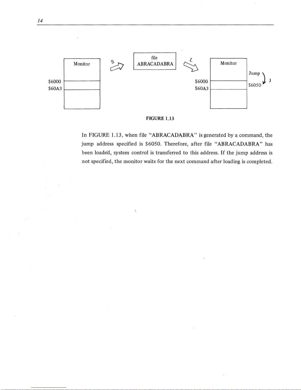
L command. See FIGURE 1.13.
Page 19
14
Monitor
$6000
1-------i
$60A3
1---------i
ftle
ABRACADABRA
FIGURE 1.13
Monitor
Jump\
$6000
t--------l
.J,
J
$60A3
t---------i
$
6050
In
FIGURE 1.13, when file "ABRACADABRA"
is
generated
by
a command,
the
jump
address specified is $6050. Therefore,
after
file "ABRACADABRA" has
been loaded, system control
is
transferred
to
this address .
If
the
jump
address
is
not
specified,
the
monitor
waits for the
next
command
after
loading is completed.
Page 20
15
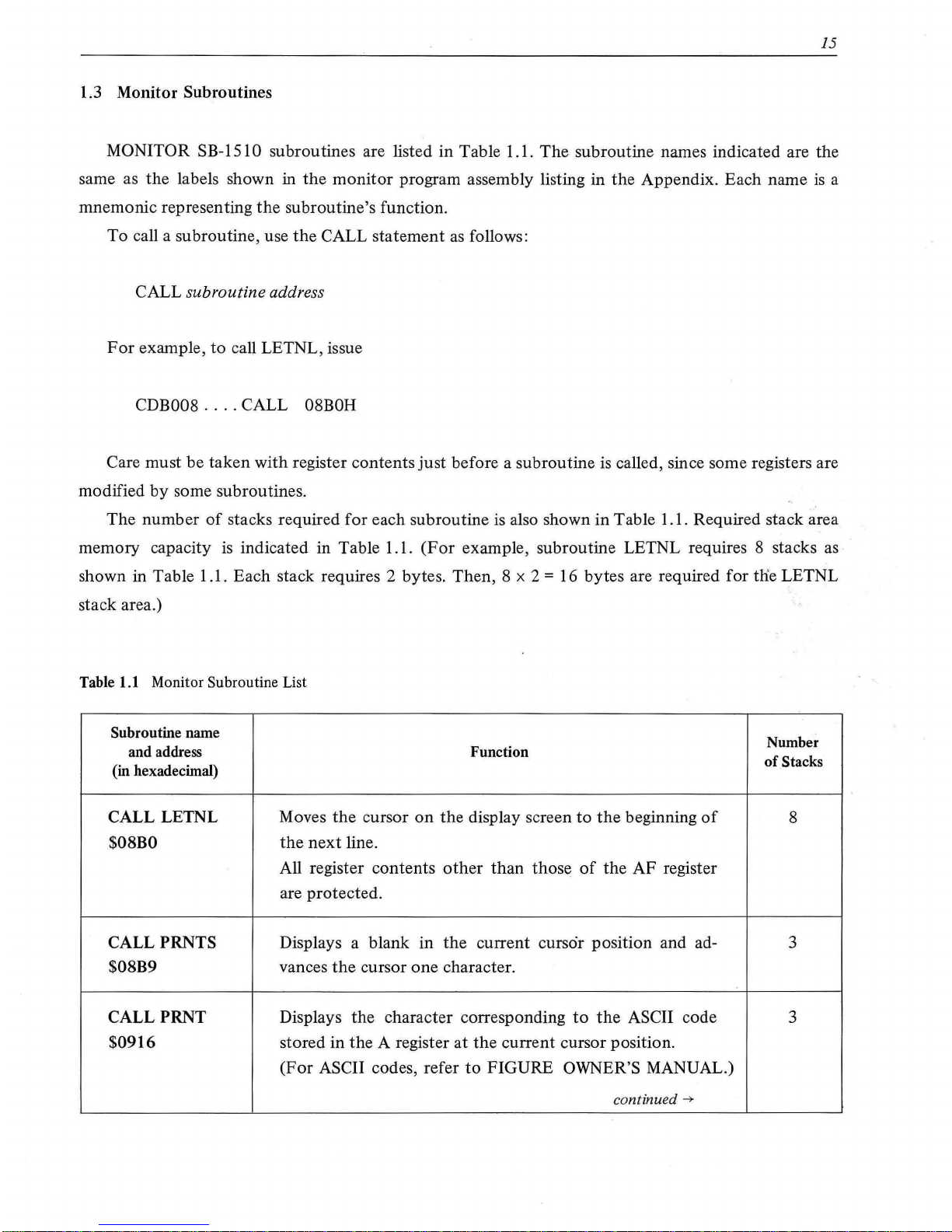
1.3 Monitor Subroutines
MONITOR SB-151 0 subroutines are listed in Table 1.1.
The
subroutine names indicated are the
same as the labels shown in
the
monitor
program assembly listing in
the
Appendix. Each name
is
a
mnemonic representing
the
subroutine's function.
To
call a subroutine, use
the
CALL statement
as
follows:
CALL
subroutine address
For
example,
to
call LETNL, issue
CDB008
....
CALL 08BOH
Care must be taken with register contents
just
before a subroutine
is
called, since some registers are
modified
by
some subroutines.
The
number
of
stacks required
for
each subroutine
is
also shown in Table 1.1. Required stack area
memory capacity
is
indicated in Table 1.1.
(For
example, subroutine LETNL requires 8 stacks as·
shown in Table 1.1. Each stack requires 2 bytes. Then, 8 x 2
= 16 bytes are required for tlie LETNL
stack area.)
Table
1.1
Monitor Subroutine List
Subroutine name
Number
and address
Function
of
Stacks
(in hexadecimal)
CALL LETNL Moves
the
cursor
on
the
display screen
to
the
beginning
of
8
$08BO
the
next
line.
All register contents
other
than
those
of
the
AF
register
are protected.
CALL
PRNTS Displays a blank
in
the
current
cursor position and ad-
3
$08B9 vances
the
cursor one character.
CALLPRNT
Displays the character corresponding
to
the
ASCII code 3
$0916 stored in the A register
at
the
current cursor position.
(For
ASCII codes, refer
to
FIGURE OWNER'S MANUAL.)
continued
--7
Page 21

16
Subroutine name
Number
and address Function
(in hexadecimal)
of
Stacks
Note
that
ASCII codes $01 through
$OF
are control codes;
when any
of
these characters are stored in the A register,
the
corresponding display control
is
performed.
For
example, $01 performs
the
same function as
the
CfJ
key.
CALL MSG
Display characters stored in the area whose start address
is
4
$08DB
stored in
the
DE register, starting at the cursor position
and continuing until
$0D
(the
carriage
return
code) is en-
countered. Carriage
return
is
not
performed in this case.
Display control
is
performed
with
ASC codes
$01-$0A,
$0C, $0E
and
$OF.
All register contents are protected.
CALL BELL Sounds middle range
tone
(about
440
Hz) for a short time.
4
$0EBE
CALLMELDY
Plays music according
to
music data.
The
music data area
4
$0EE9
start address must
be
set in
the
DE register in advance.
Music data
is
coded in
the
same manner as described
for
the
MUSIC statement in the BASIC Language Manual.
The
end mark
is
$0D (carriage return)
or$2A(*).
When con-
trol
is
returned
to
the
calling program, the C flag has
the
following meanings:
0 - play has been completed.
1
-play
has been stopped
by
the
[BREAK]
key.
CALL XTEMP
Specifies
the
tempo
at which music
is
played.
Tempo
data
3
$0DF8
($0 1-$07) must be set in
the
A register in advance.
$01: Lowest
tempo
$04
: Medium
tempo
$07: Highest
tempo
CALL SOUT
Sounds a
tone
of
the desired pitch and duration. The
pitch
3
$0ECC
and duration must be set, respectively,
in
the
HL and
BC
registers in advance.
(For
example, when $00A4
is
set in
the
HL register,
the
pitch is middle la).
Page 22
Subroutine
name
and
address
(in
hexadecimal)
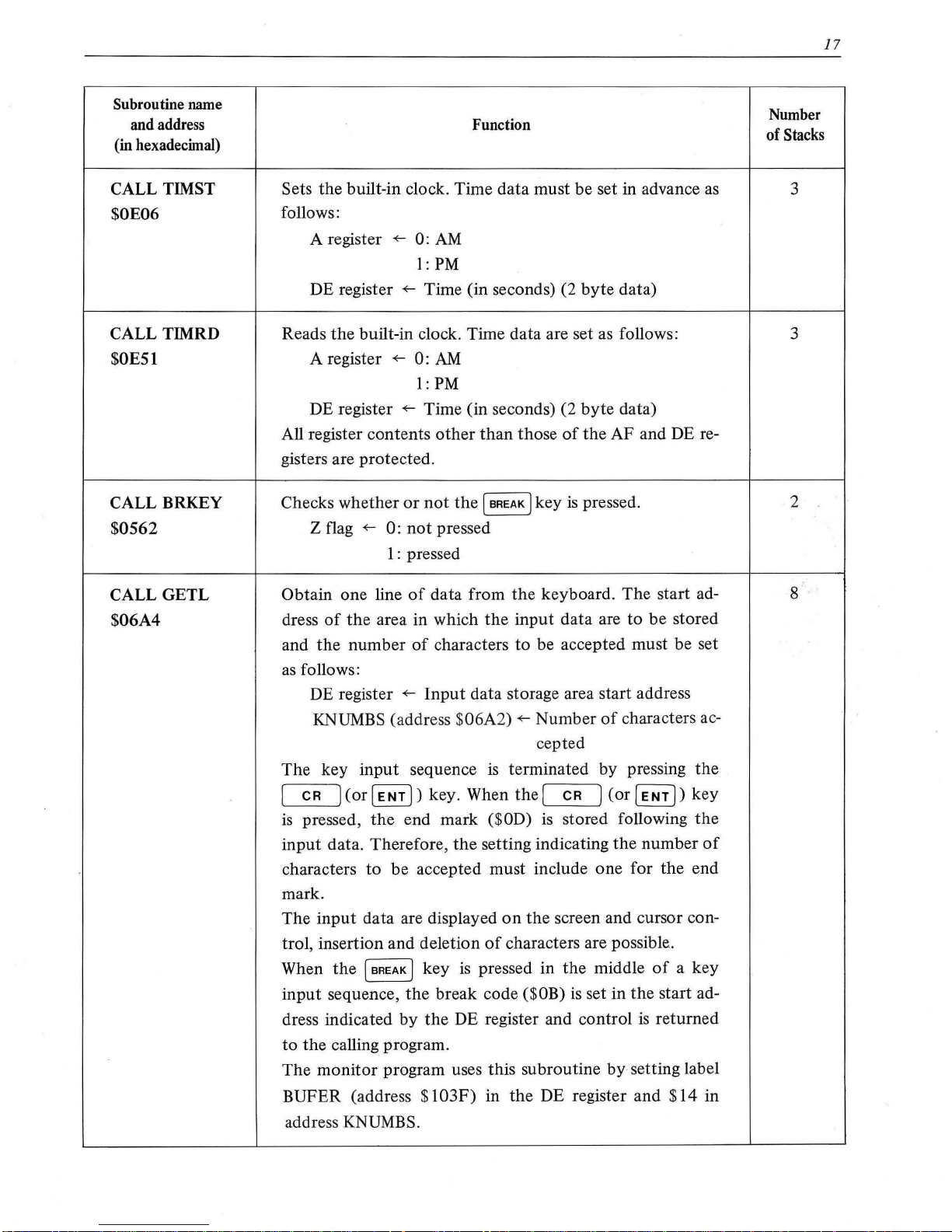
CALL TIMST
$0E06
CALLTIMRD
$0E51
CALL BRKEY
$0562
CALL
GETL
$06A4
Function
Sets the built-in clock. Time data must be set in advance
as
follows:
A register
+--
0:
AM
1:
PM
DE register
+--
Time (in seconds) (2
byte
data)
Reads
the
built-in clock. Time data are set as follows:
A register
+--
0:
AM
1: PM
DE register
+--
Time (in seconds) (2
byte
data)
All register contents
other
than
those
of
the
AF and DE re-
gisters are
protected
.
Checks whether
or
not
the
(
BREAK
J key
is
pressed .
Z flag
+--
0:
not
pressed
1:
pressed
Obtain one line
of
data from
the
keyboard.
The
start ad-
dress
of
the
area in which
the
input
data are to be stored
and
the
number
of
characters
to
be accepted must be set
as
follows:
DE register
+--
Input
data storage area start address
KNUMBS (addre
ss
$06A2)
+--
Number
of
characters ac-
cepted
The
key
input
sequence
is
terminated by pressing
the
(
CR
]
(or
[
ENT])
key. When
the
[
CR
]
(or
(
ENT
j)
key
is
pressed,
the
end mark ($0D)
is
stored following
the
input
data. Therefore,
the
setting indicating
the
number
of
characters to be accepted must include
one
for the end
mark.
The
input
data are displayed
on
the
screen and cursor con-
trol, insertion and deletion
of
characters are possible .
When
the
(BREAK] key
is
pressed in
the
middle
of
a key
input
sequence,
the
break code ($0B)
is
set in
the
start ad-
dress indicated by
the
DE register and control
is
returned
to
the
calling program.
The
monitor
program uses this subroutine
by
setting label
BUFER (address
$103F)
in
the
DE register and
$14
in
address
KNUMBS.
17
Number
of
Stacks
3
3
2
8
Page 23
18
Subroutine name
and address
(in hexadecimal)
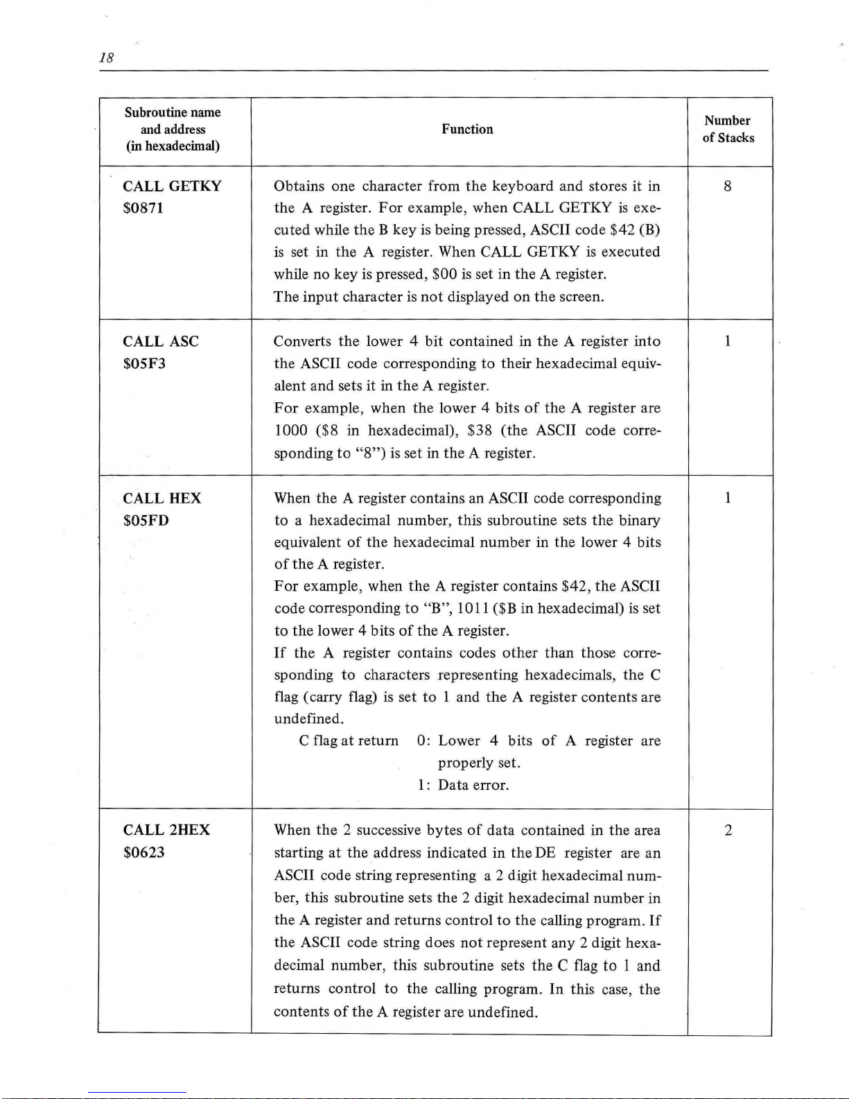
CALL GETKY
$0871
CALL ASC
$05F3
CALL HEX
$05FD
CALL 2HEX
$0623
Function
Obtains one character from
the
keyboard and stores it in
the
A register.
For
example, when CALL GETKY
is
exe-
cuted while
the B key
is
being pressed, ASCII code $42 (B)
is
set in
the
A register. When CALL GETKY
is
executed
while no key is pressed,
$00
is set
in
the
A register.
The
input
character
is
not
displayed
on
the
screen.
Converts
the
lower 4
bit
contained in
the
A register
into
the
ASCII code corresponding
to
their hexadecimal equiv-
alent and sets it in
the
A register.
For
example, when
the
lower 4 bits
of
the
A register are
1000 ($8 in hexadecimal), $38
(the
ASCII code corre-
sponding
to
"8")
is set in
the
A register.
When the A register contains an
ASCII code corresponding
to
a hexadecimal number, this subroutine sets
the
binary
equivalent
of
the
hexadecimal
number
in
the
lower 4 bits
of
the
A register.
For
example, when
the
A register contains $42,
the
ASCII
code corresponding
to
"B",
lOll
($Bin
hexadecimal)
is
set
to
the
lower 4 bits
of
the
A register.
If
the A register contains codes
other
than
those corre-
sponding
to
characters representing hexadecimals,
the
C
flag (carry flag)
is
set
to
1 and
the
A register contents are
undefined.
C flag
at
return
0: Lower 4 bits
of
A register are
properly set.
1:
Data error.
When
the
2 successive
bytes
of
data contained in the area
starting
at
the
address indicated in
the
DE register are an
ASCII code string representing a 2 digit hexadecimal number, this subroutine sets the 2 digit hexadecimal number in
the A register and returns control
to
the
calling program.
If
the
ASCII code string does
not
represent any 2 digit hexa-
decimal number, this subroutine sets
the
C flag
to
1 and
returns control
to
the
calling program.
In
this case,
the
contents
of
the
A register are undefined.
Number
of
Stacks
8
2
Page 24
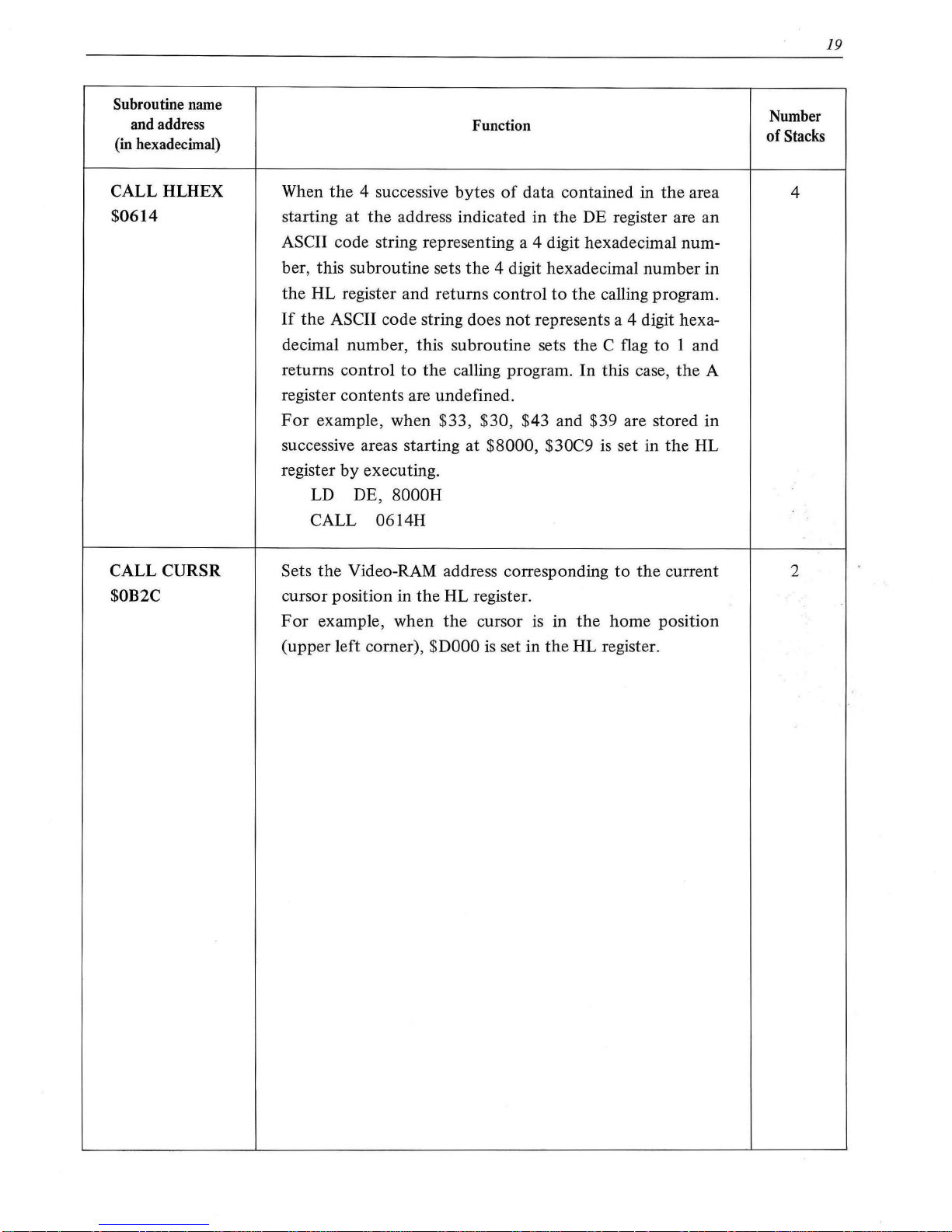
Subroutine name
and address
(in hexadecimal)
CALL HLHEX
$0614
CALL
CURSR
$0B2C
Function
When
the
4 successive bytes
of
data contained in
the
area
starting
at
the
address indicated in
the
DE register are an
ASCII code string representing a 4 digit hexadecimal number, this subroutine sets
the
4 digit hexadecimal number in
the
HL register and returns control
to
the
calling program.
If
the
ASCII code string does
not
represents a 4 digit hexa-
decimal number, this subroutine sets
the
C flag
to
1 and
returns control
to
the
calling program. In this case,
the
A
register contents are undefined.
For
example, when $33, $30 , $43 and $39 are stored in
successive areas starting at
$8000, $30C9
is
set in
the
HL
register
by
executing.
LD DE,
8000H
CALL 0614H
Sets
the
Video-RAM address corresponding
to
the
current
cursor position in the HL register.
For
example, when
the
cursor
is
in
the
home position
(upper left comer),
$DOOO
is
set in
the
HL register.
Number
of
Stacks
4
2
19
Page 25

Page 26
APPENDIX
Correspondence between each object
(08
j)
code and mnemonic code
is
shown in sections A. 7 and
A.2.
In
A.
7,
mnemonic codes
are
arranged in the alphabetic order; this arrangement
is
convenient
when cross-referencing from
ZBOA
CPU
instructions to corresponding object codes.
In
A.2, object
codes
are
arranged in hexadecimal order; this arrangement
is
convenient when it
is
necessary to look
up the mnemonic code corresponding to a particular object code.
Details on operation,
flag
operation, execution time, etc., for each instruction
are
contained in the
ZBOA
CPU
reference data
in
the appendix
of
the MZ-808 OWNER's MANUAL.
The
MONITOR 58-7 570 assembly listing
is
shown in
A.3
.
21
Page 27
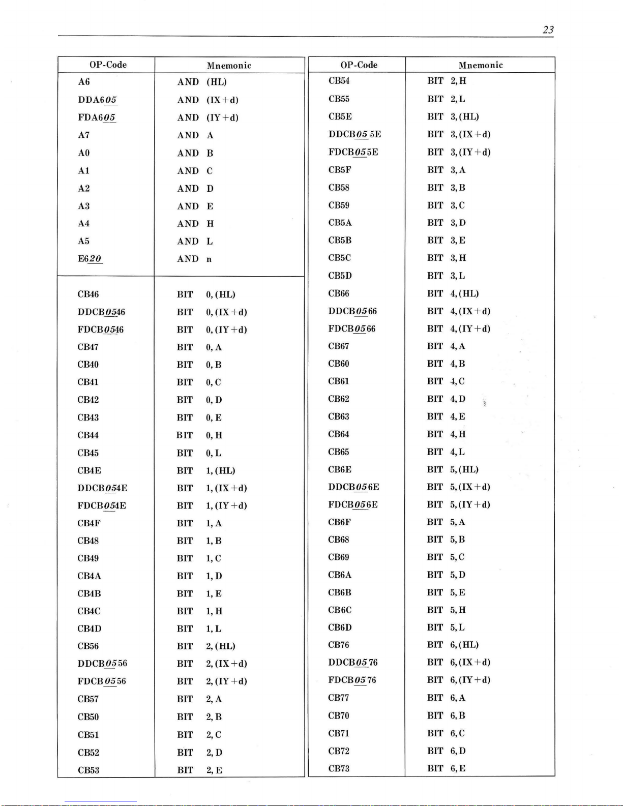
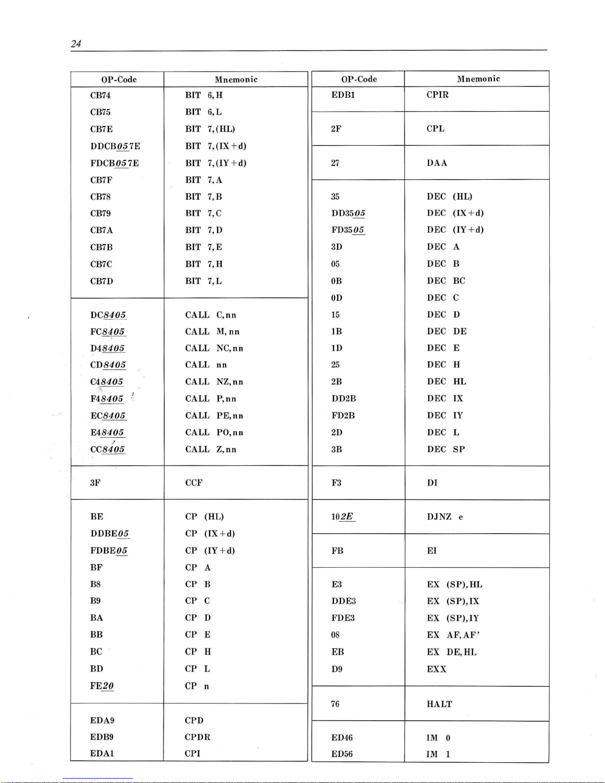
22
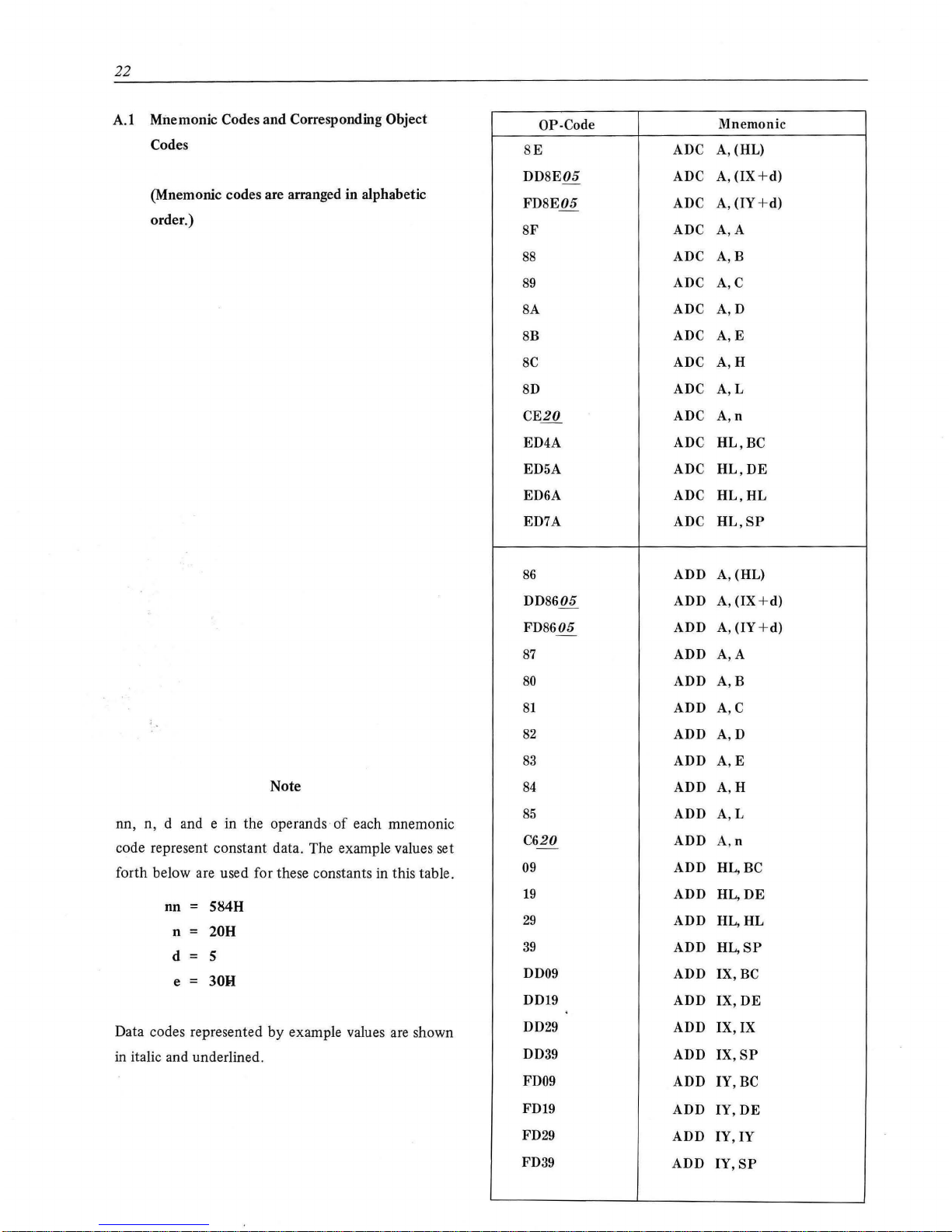
A.l
Mnemonic Codes and Corresponding Object
Codes
(Mnemonic codes are arranged in alphabetic
order.)
Note
nn, n, d and e in the operands
of
each mnemonic
code represent constant data. The example values set
forth below are used for these constants in this table.
nn = 5848
n =
208
d s
e = 30H
Data codes represented
by
example values are shown
in
italic and underlined.
OP-Code
BE
DDSE05
-
FD8E05
SF
ss
S9
SA
SB
SC
SD
CE20
ED4A
ED5A
ED6A
ED7A
86
DD8605
FD8605
-
87
80
81
82
83
84
85
C620
-
09
19
29
39
DD09
DD19
DD29
DD39
FD09
FD19
FD29
FD39
Mnemonic
ADC
A,
(HL)
ADC
A,
(IX
+d)
ADC
A,
(IY +d)
ADC
A,
A
ADC
A,B
ADC
A,C
ADC
A,D
ADC
A,E
ADC
A,H
ADC
A,L
ADC
A,n
ADC
HL,BC
ADC
HL,DE
ADC
HL,HL
ADC
HL,SP
ADD
A,
(HL)
ADD
A,
(IX +d)
ADD
A,
(IY
+d)
ADD
A,
A
ADD
A,B
ADD
A,C
ADD
A,D
ADD
A,E
ADD
A,H
ADD
A,L
ADD
A,n
ADD
HL,BC
ADD HL,
DE
ADD
HL,HL
ADD
HL,SP
ADD
IX,BC
ADD
IX,
DE
ADD
IX,
IX
ADD
IX,SP
ADD
IY,BC
ADD
IY,DE
ADD
IY,IY
ADD
IY,SP
Page 28
23
OP-Code
Mnemonic
OP-Code
Mnemon ic
A6
AND
(HL)
CB54
BIT
2,H
DDA605
AND
(IX + d)
CB55
BIT
2,L
-
FDA605
AND
(IY
+d)
CB5E
BIT
3,(HL)
A7
AND A
DDCB055E
BIT
3,
(IX
+d)
-
AO
AND
B
FDCB055E
-
BIT
3,
(IY + d)
AI
AND
c
CB5F
BIT
3,A
A2
AND
D
CB58
BIT
3,B
A3
AND
E
CB59
BIT
3,C
A4
AND
H
CB5A
BIT
3,D
A5
AND
L
CB5B BIT
3,E
E620
AND n
CB5C BIT
3,H
CB5D
BIT
3,L
CB46
BIT
0,
(HL)
CB66
BIT
4,(HL)
DDCB0546
BIT
0,
(IX
+d)
DDCB0566
BIT
4,(1X + d)
-
FDCB0546
BIT
0,
(IY + d)
FDCB0566 BIT
4,(1Y
+d)
CB47
BIT O,A
CB67
BIT
4,A
CB40
BIT
O,B
CB60
BIT
4,B
CB41
BIT
0,
c
CB61
BIT 4,C
CB42
BIT
O,D
CB62
BIT
4,D
~
CB43
BIT
0,
E
CB63
BIT
4,E
CB44
BIT
O,H
CB64
BIT
4,H
CB45
BIT
O,L
CB65
BIT 4,L
CB4E
BIT
1,
(HL)
CB6E BIT
5,(HL)
DDCB054E
BIT
1,
(IX
+d)
DDCB056E
BIT
5,(1X+d)
-
-
FDCB054E
BIT
1,
(IY
+d)
FDCB056E
BIT
5,
(IY
+d)
-
CB4F BIT
l,A
CB6F BIT
5,A
CB48 BIT
l,B
CB68
BIT
5,B
CB49 BIT
1,
c
CB69
BIT
5,C
CB4A BIT
1,
D
CB6A BIT
5,D
CB4B
BIT
1,
E
CB6B BIT
5,E
CB4C BIT
1,
H
CB6C BIT
5,H
CB4D BIT
1,
L
CB6D BIT
5,L
CB56
BIT
2,
(HL)
CB76
BIT
6,(HL)
DDCB0556
BIT
2,
(IX
+d)
DDCB0576
BIT
6,(1X+ d)
-
FDCB0556
BIT
2,
(IY
+d)
FDCB0576
BIT
6,(IY+d)
-
-
CB57
BIT
2,A
CB77
BIT
6,A
CB50
BIT
2,B
CB70
BIT
6,B
CB51
BIT
2,C
CB71
BIT 6,C
CB52 BIT
2,
D
CB72
BIT
6,D
CB53
BIT
2,
E
CB
73 BIT
6,E
Page 29
24
OP-Code
Mnemonic
OP-Code
Mnemonic
CB74
BIT
6,H
EDBl
CPIR
CB75
BIT
6,L
CB7E
BIT
7,(HL) 2F
CPL
DDCB057E
BIT
7,(IX+d)
FDCB057E
BIT
7,(1Y + d)
27
DAA
-
CB7F BIT
7,A
CB78
BIT
7,B
35
DEC
(HL)
CB79
BIT 7,C
DD3505 DEC
(IX + d)
-
CB7A BIT
7,D
FD3505 DEC
(IY
+d)
-
CB7B BIT
7,E
3D
DEC A
CB7C
BIT
7,H
05
DEC B
CB7D
BIT
7,L
OB
DEC
BC
OD
DEC c
DC8405
CALL
C,n
n
15
DEC D
FC8405
CALL
M,nn
1B DEC
DE
D48405
CALL
NC,nn
1D
DEC E
CD8405
CALL
nn
25
DEC H
--
C48405
CALL
NZ,nn
2B
DEC
HL
.
..---------
F48405
!
CALL
P,nn
DD2B DEC IX
- -
EC8405
CALL
PE,nn
FD2B DEC IY
E48405
CALL
PO,nn
2D
DEC
L
- -
.!
CC8405
CALL
Z,nn
3B DEC
SP
3F
CCF F3
DI
BE
CP
(HL)
102E
DJNZ
e
DDBE05
CP
(IX
+d)
-
FDBE05
CP
(IY
+d)
FB
EI
-
BF
CP
A
BS
CP
B
E3 EX
(SP),HL
B9
CP
c DDE3
EX
(SP),IX
BA
CP
D
FDE3 EX
(SP),
IY
BB
CP
E
08
EX
AF,AF'
BC CP H
EB
EX
DE,HL
BD CP L
D9
EXX
FE20
CP
n
-
76
HALT
EDA9 CPD
EDB9
CPDR
ED46
IM
0
EDA1
CPI
ED
56
IM 1
Page 30

25
OP-Code Mnemonic
OP-Code
Mnemonic
ED5E IM 2
C28405
JP
NZ,nn
- -
F28405
JP
P,nn
ED78 IN
A,(C)
EA8405
JP
PE,nn
--
DB20
IN
A,
(n)
E28405
JP
PO,
nn
ED40
IN
B,(C)
CA8405
JP
Z,nn
--
ED48 IN
C,(C)
ED
50
IN
D,(C)
382E
JR
C,e
-
ED
58
IN
E,(C)
182E
JR
e
--
-
ED60 IN
H,(C)
302E
JR NC,e
ED68 IN
L,(C)
202E
JR
NZ,e
282E
JR
Z,e
-
34
INC
(HL)
DD3405
INC
(IX + d)
02
LD
(BC),A
-
FD3405
INC
(IY
+d)
12
LD
(DE), A
-
3C
INC
A
77
LD
(HL),A
04
INC B
70
LD
(HL),B
03
INC
BC
71
LD
(HL),C
oc
INC
c
72
LD
(HL), D
~.-.
14
INC
D
73
LD
(HL), E
..
13
INC
DE
74
LD
(HL),H
. .
.
1C
INC
E
75
LD
(HL),L
..
..
24
INC
H
3620
LD
(HL), n
'
23
INC HL
DD7705
LD
(IX+d),A
-
DD23 INC
IX
DD7005
LD
(IX+
d),B
FD23 INC
IY
DD7105
LD
(IX+d),C
-
2C
INC
L
DD7205
LD
(IX + d)
,D
33
INC
SP
DD7305
LD
(IX
+d),E
DD7405
LD
(IX
+d),H
-
EDAA
IND
DD7505
LD
(IX +
d),L
EDBA
INDR
DD360520
LD
(IX
+d),
n
EDA2
INI
FD7705
LD
(IY+
d),A
EDB2
INIR
FD7005
LD
(IY+d),B
FD7105
LD
(IY+d),C
E9
JP
(HL)
FD7205
LD
(IY+d),D
-
DDE9
JP
(IX)
FD7305
LD
(IY
+d),E
FDE9
JP
(IY)
FD7405
LD
(IY+
d),H
DA8405
JP
C,nn
FD7505
LD
(IY+d),L
-
--
FA8405
JP
M,nn
FD360520
LD
(IY+d),n
--
D28405
JP
NC,nn
328405
LD
(nn),A
--
C38405
JP
nn
ED438405
LD
(nn),
BC
Page 31

26
OP-Code
Mnemonic
OP-Code
Mn
emon
ic
ED
538405
LD
(nn),DE
4B
LD
C,E
228405
LD
(nn),HL
4C
LD
C,H
DD228405
LD
(nn),IX
4D
LD
C,L
FD228405
LD
(nn),IY
OE20
LD
C,n
-
ED738405
LD
(nn),
SP
56
LD D,(HL)
OA
LD
A,(BC)
DD5605
LD
D,(IX +
d)
lA
LD
A,(DE)
FD5605
LD
D,(IY+d)
7E
LD
A,(HL)
57
LD
D,A
DD7E05
LD
A,
(IX +d)
50
LD
D,B
FD7E05
LD
A,(IY+d)
51
LD
D,C
3A8405
LD
A,(nn)
52
LD
D,D
7F
LD
A,
A
53
LD
D,E
78
LD
A,B
54
LD
D,H
79
LD
A,C
55
LD
D,L
7A
LD
A,D
1620
LD
D,n
-
7B
LD
A,E
ED5B8405
LD
DE,(nn)
- -
7C
LD
A,H
118405
LD
DE,nn
--
ED
57
LD
A,
I
5E
LD
E,(HL)
7D
LD
A,L
DD5E05
LD
E,(IX +d)
-
3E20
LD
A,n
FD5E05
LD
E,(IY +d)
-
46
LD
B,(HL)
5F
LD
E,A
DD4605
LD
B,(IX +
d)
58
LD
E,B
'
FD4605
LD
B,(IY+d)
59
LD
E,C
47
LD
B,A
5A
LD
E,D
40
LD
B,B
5B
LD
E,E
41
LD
B,C
5C
LD
E,H
42
LD
B,D
5D
LD
E,L
43
LD
B,E
1E20
LD
E,n
-
44
•
LD
B,H
66
LD
H,(HL)
45
LD
B,L
DD6605
-
LD
H,(IX +d)
0620
LD
B,n
FD6605
LD
H,(IY +
d)
-
ED4B8405
LD
BC,
(nn)
67
LD
H,A
018405
LD
BC,nn
60
LD
H,B
4E
LD
C,(HL)
61
LD
H,C
DD4E05
LD
C,(IX+d)
62
LD
H,D
FD4E05
LD
C,(IY +d)
63
LD
H,E
4F
LD
C,A
64
LD
H,H
48
LD
C,B
65
LD
H,L
49
LD
C,C
2620
LD
H,n
4A
LD
C,D
2A8405
LD
H,(nn)
--
Page 32

27
OP-Co
de
Mnem
onic
OP-Code
Mnemon
ic
2184 05
LD HL,nn
B4
OR
H
ED47
LD
I, A
B5
OR
L
DD2A8405
LD
I
X,(nn) F620
OR
n
--
-
DD21
8405
LD I
X,n
n
- -
FD2A8405
LD
I
Y,(
nn)
EDBB
OTD R
--
FD21
8405
LD
IY,nn
EDB3
OTIR
6E LD
L,(H
L)
ED79
OUT
(C), A
DD6E05
LD
L,(IX
+d)
ED41 OUT
(C),B
FD6E 05 LD
L,(IY
+ d)
ED49
OUT
(C),C
-
6F
LD
L,A
ED
51
OUT
(C),D
68
LD
L,B
ED
59
OUT
(
C),E
69
LD
L,C
ED61 OUT
(C),H
6A LD
L,D
ED69
OUT
(C), L
6B
LD
L,E
D320
OUT
(n),A
-
6C
LD
L,H
EDAB
OUTD
6D
LD
L,L
EDA3
OUTI
2E20
LD
L,n
-
ED7B8405
LD
SP,(n
n) F l
POP
AF
--
F9
LD
SP,HL
Cl
POP
BC
~
DDF9
LD
SP,IX
Dl
POP
DE
FDF9
LD
SP,IY
El
POP
HL
318405
LD
SP,n
n
DDE
I
POP
IX
;
FDEI
POP
IY
EDAS
LDD
EDBS
LD
DR
F5
PUSH AF
EDAO
LDI
C5
PUSH
BC
EDBO
LDIR
D5
PUSH DE
E5
PUSH
HL
ED44
NEG
DDE5
PUSH
IX
FDE5
PUS
H IY
00
NOP
CB86
RES
0,
(HL
)
B6
OR
(HL)
DDCB0586
RES
0,
(IX + d)
DDB605
OR
(IX + d)
FDCB0586
RES
O,(IY +d)
-
-
FDB605
OR
(IY
+d)
CB87
RES
O,A
-
B7
OR A
CBSO
RES
O,B
BO
OR B
CBSI
RES
O,C
Bl
OR C
CB82
RES
O,D
B2
OR
D
CB83
RES
O,E
B3
OR
E
CB84
RES
O,H
Page 33

28
OP-Code
Mnemonic
OP-Code
Mnemonic
CB85
RES
O,L
CBA5
RES
4,1
CB8E
RES
1,
(HL)
CBAE
RES
5,
(HL)
DDCB058E
RES
l,(IX
+ d)
DDCB05AE
RES
5,
(IX
+d)
--
FDCB058E
RES
l,(IY+d)
FDCB05AE
RES
5,
(IY + d)
-
-
CB8F
RES
l,A
CBAF
RES
5,A
CB88
RES
l,B
CBA8
RES
5,B
CB89
RES
l,C
CBA9
RES
5,C
CB8A
RES
l,D
CBAA
RES
5,D
CB8B
RES
l,E
CBAB
RES
5,E
CB8C
RES
l,H
CBAC
RES
5,H
CB8D
RES
l,L
CBAD
RES
5,L
CB96
RES
2,(HL)
CBB6
RES
6,(HL)
DDCB0596
RES
2,(IX + d)
DDCB05B6
RES
6,(IX+d)
FDCB0596
RES
2,(IY + d)
FDCB05B6
RES
6,
(IY
+d)
-
-
CB97
RES
2,A
CBB7
RES
6,A
CB90
RES
2,B
CBBO
RES
6,B
CB91
RES
2,C
CBBl
RES
6,C
CB92
RES
2,D
CBB2
RES
6,D
CB93
RES
2,E
CBB3
RES
6,E
CB94
RES
2,H
CBB4
RES
6,H
CB95
RES
2,L
CBB5
RES
6,L
CB9E
RES
3,(HL)
CBBE
RES
7,(HL)
DDCB059E
RES
3,(IX + d)
DDCB05BE
RES
7,(1X + d)
FDCB059E
RES
3,
(IY
+d)
FDCB05BE
RES
7,(IY+ d)
-
-
CB9F
RES
3,A
CBBF
RES
7,A
CB98
RES
3,B
CBB8
RES
7,B
CB99
RES
3,C
CBB9
RES
7,C
CB9A
RES
3,D
CBBA
RES
7, D
CB9B
RES
3,E
CBBB
RES
7,E
CB9C
RES
3,H
CBBC
RES
7,H
CB9D
RES
3,L
CBBD
RES
7,L
CBA6
RES
4,(HL)
DDCB05A6
RES
4,(1X
+d)
C9
RET
FDCB05A6
RES
4,(1Y + d)
D8
RET
c
CBA7
RES
4,A
F8
RET
M
CBAO
RES
4,B
DO
RET
NC
CBAl
RES
4,C
co
RET
NZ
CBA2
RES
4,D
FO
RET
p
CBA3
RES
4,E
E8
RET
PE
CBA4
RES
4,H
EO
RET
PO
Page 34

29
OP-Code
Mnemonic
OP-Code
Mnemonic
cs
RET
z
CBOE
RRC
(HL)
ED4D
RETI
DDCB050E
RRC
(IX
+d)
ED45
RETN
FDCB050E
RRC
(IY
+ d)
CBOF
RRC
A
CBI6
RL
(HL)
CBOS
RRC
B
DDCB05I6
RL
(IX
+d)
CB09
RRC
c
-
FDCB05I6
RL
(IY
+d)
CBOA
RRC
D
-
CBI7
RL
A
CBOB
RRC
E
CBIO
RL
B
CBOC
RRC
H
CEll
RL
c
CBOD
RRC
L
CBI2
RL
D
OF
RRCA
CBI3
RL
E
CBI4
RL
H ED67
RRD
CBI5
RL
L
I7 RLA C7
RST
0
CB06
RLC
(HL)
D7
RST
IOH
DDCB0506
RLC
(IX
+ d)
DF
RST
ISH
FDCB0506
RLC
(IY
+d)
E7
RST
20H
-
CB07
RLC A
EF
RST
28H
CBOO
RLC
B
F7
RST
30H
CBOI
RLC c
FF
RST
38H
CB02 RLC D
CF
RST
8
/
CB03
RLC E
CB04 RLC
H
9E
SBC
A,(HL)
CB05
RLC L
DD9E05
SBC
A,(IX+d)
-
07
RLCA
FD9E05
SBC
A,(IY
+d)
9F
SBC
A, A
ED6F
RLD
98
SBC
A,B
99
SBC
A,C
CBIE
RR
(HL) 9A SBC
A,D
DDCB05IE
RR
(IX + d) 9B
SBC
A,E
-
FDCB05IE
RR
(IY
+d)
9C
SBC
A,H
-
CBIF
RR
A
9D
SBC
A,L
CBI8
RR
B
DE20
SBC
A,n
-
CBI9
RR
c
ED42
SBC
HL,BC
CBIA
RR
D
ED
52
SBC
HL,DE
CBlB
RR
E
ED62
SBC
HL,HL
CBIC
RR
H
ED72
SBC
HL,SP
CBID
RR
L
IF
RRA
37
SCF
Page 35

30
OP-Code
Mnemonic
OP-Code Mnemonic
CBC6
SET
0,
(HL)
CBE6
SET
4,
(HL)
DDCB05C6
SET
O,(IX
+d)
DDCB05E6
SET
4,
(IX
+d)
-
FDCB05C6
SET
0,
(IY
+d)
FDCB05E6
SET
4,
(IY
+d)
-
-
CBC7
SET
O,A
CBE7
SET
4,A
CBCO
SET
O,B
CBEO
SET
4,B
CBCI
SET
O,C
CBEI
SET
4,C
CBC2
SET
O,D
CBE2
SET
4,D
CBC3
SET
O,E
CBE3
SET
4,
E
CBC4
SET
O,H
CBE4
SET
4,H
CBC5
SET
O,L
CBE5
SET
4,L
CBCE
SET
l,(HL)
CBEE
SET
5,
(HL)
DDCB05CE
SET
l,(IX
+ d)
DDCB05EE
SET
5,
(IX
+d)
FDCB05CE
SET
1,
(IY
+d)
-
FDCB05EE
SET
5,
(IY + d)
CBCF
SET
I,
A
CBEF
SET
5,A
CBCS
SET
l,B
CBES
SET
5,B
CBC9
SET
l,C
CBE9
SET
5,C
CBCA
SET
l,D
CBEA
SET
5,D
CBCB
SET
l,E
CBEB
SET
5,E
CBCC
SET
l,H
CBEC
SET
5,H
CBCD
SET
l,L
CBED
SET
5,L
CBD6
SET
2,(HL)
CBF6
SET
6,
(HL)
DDCB05D6
SET
2,(1X + d)
DDCB05F6
SET
6,
(IX+d)
-
FDCB05D6
SET
2,
(IY
+d)
FDCB05F6
SET
6,
(IY + d)
-
-
CBD7
SET
2,A
CBF7
SET
6,A
CBDO
SET
2,B
CBFO
SET
6,B
CBDI
SET
2,C
CBFI
SET
6,C
CBD2
SET
2,D
CBF2
SET
6,D
CBD3
SET
2,E
CBF3
SET
6,E
CBD4
SET
2,H
CBF4
SET
6,H
CBD5
SET
2,L
CBF5
SET
6,L
CBDS
SET
3,B
CBFE
SET
7,
(HL)
CBDE
SET
3,(HL)
DDCB05FE
SET
7,
(IX+ d)
DDCB05DE
SET
3,(1X + d)
FDCB05FE
SET
7, (IY + d)
-
FDCB05DE
-
SET
3,
(IY +d)
CBFF
SET
7,A
CBDF
SET
3,A
CBFS
SET
7,B
CBD9
SET
3,C
CBF9
SET
7,C
CBDA
SET
3,D
CBFA
SET
7,
D
CBDB
SET
3,E
CBFB
SET
7,
E
CBDC
SET
3,H
CBFC
SET
7,H
CBDD
SET
3,L
CBFD
SET
7,L
Page 36

31
OP-Code
Mnemonic
OP-Code
Mnemonic
CB26
SLA
(HL)
93
SUB
E
DDCB0526
SLA
(IX + d)
94
SUB
H
-
FDCB0526
SLA
(IY
+d)
95
SUB
L
-
CB27
SLA A
D620
SUB
n
-
CB20
SLA
B
CB21
SLA
c
AE
XOR
(HL)
CB22
SLA
D
DDAE05
XOR (IX + d)
-
CB23
SLA
E
FDAE05
XOR (IY + d)
-
CB24
SLA H
AF
XOR A
CB25
SLA L
AS
XOR
B
A9
XOR c
CB2E
SRA
(HL)
AA
XOR D
DDCB052E
SRA
(IX + d)
AB
XOR E
-
FDCB052E
SRA
(IY + d)
AC
XOR H
-
CB2F
SRAA
AD XOR L
CB28
SRA
B
EE20
XOR n
-
CB29
SRA
C
CB2A
SRA
D
CB2B
SRA
E
CB2C
SRA
H
CB2D
SRA
L
CB3E
SRL
(HL)
DDCB053E
SRL
(IX
+d)
-
FDCB053E
SRL
(IY
+d)
-
CB3F
SRL
A
CB38
SRL
B
CB39
SRL
c
CB3A
SRL
D
CB3B
SRL
E
CB3C
SRL
H
CB3D
SRL
L
96
SUB
(HL)
DD9605
SUB
(IX + d)
-
FD9605
SUB
(IY + d)
-
97
SUB
A
90
SUB
B
91
SUB
c
92
SUB
D
Page 37

32
A.2
Object Codes and Corresponding Mnemonic
Codes
(Object codes are arranged in hexadecimal
order.)
Note
The underlined data codes shown in italic take the
following example values. These constants are represented
by
nn, n, d and e in the operands
of
each mne-
monic code.
nn
584H
n = 20H
d 5
e = 30H
Note that instructions whose first two letters are CB,
DD, ED or FD are collected
in
the last part
of
the
table.
OP-Code
00
018405
--
02
03
04
05
0620
-
07
08
09
OA
OB
oc
OD
OE20
-
OF
102E
-
118405
--
12
13
14
15
1620
-
17
182E
-
19
1A
1B
1C
1D
1E20
-
1F
202E
-
218405
--
228405
23
24
25
Mnemonic
NOP
LD
BC,nn
LD
(BC),A
INC BC
INC
B
DEC B
LD
B,n
RLCA
EX
AF,AF'
ADD
HL,BC
LD
A,(BC)
DEC
BC
INC C
DEC C
LD C,n
RRCA
DJNZ
e
LD
DE,nn
LD
(DE),
A
INC
DE
INC D
DEC D
LD
D,n
RLA
JR
e
ADD
HL,DE
LD
A,(DE)
DEC
DE
INC E
DEC E
LD
E,n
RRA
JR
NZ,e
LD
HL,nn
LD
(nn),HL
INC
HL
INC H
DEC H
Page 38

33
OP-Code
Mnemonic
OP-Code
Mnemonic
2620
LD
H,n
4C
LD
C,H
-
27
DAA
4D
LD
C,L
282E
JR Z,e
4E
LD
C,(HL)
-
29
ADD
HL,HL
4F
LD
C,A
2A8405
LD
HL,(nn)
2B
DEC
HL
50
LD
D,B
2C
INC
L
51
LD
D,C
2D
DEC
L
52
LD
D,D
2E20
LD
L,n
53
LD
D,E
- -
2F
CPL
54
LD
D,H
55
LD
D,L
302E_
JR
NC,e
56
LD
D,
(HL)
318405
LD
SP,nn
57
LD
D,A
328405
--
LD
(nn),A
58
LD
E,B
33
INC
SP
59
LD
E,C
34
INC
(HL)
5A
LD
E,D
35
DEC
(HL)
5B
LD
E,E
3620
LD
(HL),
n
5C
LD
E,H
-
37
SCF
5D
LD
E,L
382E
JR
C,e
5E
LD
E,(HL)
39
ADD
HL,SP
5F
LD
E,A
3A8405
LD
A,(nn)
--
3B
DEC
SP
60
LD
H,B
3C
INC
A
61
LD
H,C
3D
DEC
A
62
LD
H,D
3E20
-
LD
A,n
63
LD
H,E
3F
CCF
64
LD
H,H
65
LD
H,L
40
LD
B,B
66
LD
H,(HL)
41
LD
B,C
67
LD
H,A
42
LD
B,D
68
LD
L,B
43
LD
B,E
69
LD
L,C
44
LD
B,H
6A
LD
L,D
45
LD
B,L
6B
LD
L,E
46
LD
B,(HL)
6C
LD
L,H
47
LD
B,A
6D
LD
L,L
48
LD
C,B
6E
LD
L,(HL)
49
LD
c,c
6F
LD
L,A
4A
LD
C,D
4B
LD
C,E
70
LD
(HL),B
Page 39

34
OP-Code
Mnemonic
OP-Code
Mnemonic
71
LD
(HL),C
97
SUB
A
72
LD
(HL),
D
9S
SBC
A,B
73
LD
(HL),E
99
SBC
A,C
74
LD
(HL),H
9A
SBC
A,D
75
LD
(HL),L
9B
SBC
A,E
76
HALT
9C
SBC
A,H
77
LD
(HL),A
9D
SBC
A,L
7S
LD
A,B
9E
SBC
A,(HL)
79
LD
A,C
9F
SBC
A,
A
7A
LD
A,D
7B
LD
A,E
AO
AND
B
7C
LD
A,H
A1
AND
c
7D
LD
A,L
A2
AND
D
7E
LD
A,(HL)
A3
AND
E
7F
LD
A,
A
A4
AND
H
A5
AND
L
so
ADD
A,B
A6
AND
(HL)
S1
ADD
A,C
A7
AND
A
S2
ADD
A,D
AS
XOR
B
S3
ADD
A,E
A9
XOR
c
S4
ADD
A,H
AA
XOR
D
S5
ADD
A,L
AB
XOR
E
S6
ADD
A,(HL)
AC
XOR
H
S7
ADD
A,
A
AD
XOR
L
ss
ADC
A,B
AE
XOR
(HL)
S9
ADC
A,C
AF
XOR
A
SA
ADC
A,D
SB
ADC
A,E
BO
OR
B
SC
ADC
A,H
B1
OR
c
SD
ADC
A,L
B2
OR
D
SE
ADC
A,(HL)
B3
OR
E
SF
ADC
A,
A
B4
OR
H
B5
OR
L
90
SUB
B
B6
OR
(HL)
91
SUB
c
B7
OR
A
92
SUB
D
BS
CP
B
93
SUB
E
B9
CP
c
94
SUB
H
BA
CP
D
95
SUB
L
BB
CP
E
96
SUB
(HL)
BC
CP
H
Page 40

OP-Code
BD
BE
BF
co
Cl
C28405
C38405
C48405
C5
C620
C7
C8
C9
CA8405
CC8405
CD8405
CE20
CF
DO
Dl
D28405
D320
D48405
D5
D620
D7
D8
D9
DA8405
DB20
DC8405
DE20
DF
EO
El
E28405
E3
Mnemonic
CP L
CP (HL)
CP A
RET
NZ
POP
BC
JP
NZ,nn
JP
nn
CALL
NZ,nn
PUSH
BC
ADD
A,n
RST
0
RET
Z
RET
JP
Z,nn
CALL
Z,nn
CALL
nn
ADC
A,n
RST
8
RET
NC
POP
DE
JP
NC,nn
OUT
(n),A
CALL
NC,nn
PUSH
DE
SUB
n
RST
IOH
RET
C
EXX
JP
C,nn
IN
A,(n)
CALL
C,nn
SBC
A,n
RST 18H
RET
PO
POP
HL
JP
PO,nn
EX
(SP),HL
OP-Code
E48405
E5
E620
E7
E8
E9
EA8405
EB
EC8405
EE20
EF
FO
Fl
F28405
F3
F48405
F5
F620
F7
F8
F9
FA8405
FB
FC8405
FE20
FF
CBOO
CBOI
CB02
CB03
CB04
CB05
CB06
CB07
CB08
CB09
CBOA
CBOB
Mnemonic
CALL
PO,nn
PUSH
HL
AND n
RST
20H
RET
PE
JP
(HL)
JP
PE,nn
EX
DE,HL
CALL
PE,nn
XOR n
RST 28H
RET
P
POP
AF
JP
P,nn
DI
CALL
P,nn
PUSH
AF
OR n
RST
30H
RET
M
LD
SP,HL
JP
M,nn
EI
CALL
M,nn
CP n
RST 38H
RLC B
RLC C
RLC D
RLC E
RLC H
RLC L
RLC (HL)
RLC A
RRC B
RRC C
RRC D
RRC E
35
Page 41

36
OP-Code
Mnemonic
OP-Code
Mnemonic
CBOC
RRC
H CB39
SRL
c
CBOD
RRC
L CB3A
SRL
D
CBOE
RRC
(HL)
CB3B
SRL
E
·
CBOF
RRC
A CB3C
SRL
H
CB3D
SRL
L
CBlO
RL
B
CB3E
SRL
(HL)
CBll
RL
c
CB3F
SRL
A
CB
12
RL
D
CB13
RL
E
CB40
BIT
O,B
CB
14
RL
H
CB41
BIT
O,C
CB15
RL
L
CB42
BIT
O,D
CB
16
RL
(HL)
CB43
BIT
O,E
CB17
RL
A
CB44
BIT
O,H
CB18
RR
B
CB45
BIT
O,L
CB
19
RR
c
CB46
BIT
O,(HL)
CBlA
RR
D
CB47
BIT
O,A
CBlB
RR
E CB48
BIT
l,B
CBlC
RR
H
CB49
BIT
l,C
CBlD
'
RR
L CB4A
B
IT
l,D
CBlE
RR
(HL)
CB4B
BIT
l,E
CBlF
RR
A CB4C
BIT
l,H
CB4D
BIT
l,L
CB20
SLA
B CB4E
BIT
1, (HL)
CB21
SLA
c
CB4F
BIT
l,A
CB22
SLA
D
CB23
SLA
E
CB50
BIT
2,B
CB24 SLA H
CB51
BIT
2,C
CB25
SLA
L
CB52
BIT
2,D
CB26
SLA
(HL)
CB53
BIT
2,E
CB27 SLA A CB54
BIT
2,H
CB28
SRA
B CB55
BIT
2,L
CB29
SRA
c
CB56
BIT
2,(HL)
CB2A
SRA
D CB57
BIT
2,A
CB2B
SRA
E CB58
BIT
3,B
CB2C
SRA
H CB59
BIT
3,C
CB2D
SRA
L CB5A
BIT
3,D
CB2E
SRA
(HL)
CB5B
BIT
3,E
CB2F
SRA
A
CB5C
BIT
3,H
CB5D
BIT
3,L
CB38
SRL
B
CB5E
BIT
3,(HL)
Page 42

37
OP-Code
Mnemonic
OP-Code
Mnemonic
CB5F
BIT
3,A
CB84
RES
O,H
CB85
RES
O,L
CB60
BIT
4,B
CB86
RES
O,(HL)
CB61
BIT
4,C
CB87
RES
O,A
CB62
BIT
4,D
CB88
RES
l,B
CB63
BIT
4,E
CB89
RES
l,C
CB64
BIT
4,H
CB8A
RES
l,D
CB65
BIT
4,L
CB8B
RES
l,E
CB66
BIT
4,(HL)
CB8C
RES
l,H
CB67
BIT
4,A
CBSD
RES
l,L
CB68
BIT
5,B
CBSE
RES
1,
(HL)
CB69
BIT
5,C CB8F
RES
l,A
CB6A
BIT
5,D
CB6B
BIT
5,E
CB90
RES
2,B
CB6C
BIT
5,H
CB91
RES
2,C
CB6D
BIT
5,L
CB92
RES
2,D
CB6E
BIT
5,
(HL)
CB93
RES
2,E
CB6F
BIT
5,A
CB94
RES
2,H
CB95
RES
2,L
CB70
BIT
6,B
CB96
RES
2,(HL)
CB71
BIT
6,C
CB97
RES
2,A
CB72
BIT
6,D
CB98
RES
3,B
CB73
BIT
6,E
CB99
RES
3,C
CB74
BIT
6,H
CB9A
RES
3,D
CB75
BIT
6,L
CB9B
RES
3,E
CB76
BIT
6,(HL)
CB9C
RES
3,H
CB77
BIT
6,A
CB9D
RES
3,L
CB78
BIT
7,B
CB9E
RES
3,(HL)
CB79
BIT
7,C
CB9F
RES
3,A
CB7A
BIT
7,D
CB7B
BIT
7,E
CBAO
RES
4,B
CB7C
BIT
7,H
CBAl
RES
4,C
CB7D
BIT
7,L
CBA2
RES
4,D
CB7E
BIT
7,(HL) CBA3
RES
4,E
CB7F
BIT
7,A
CBA4
RES
4,H
CBA5
RES
4,L
CB80
RES
O,B
CBA6
RES
4,(HL)
CB81
RES
O,C
CBA7
RES
4,A
CB82
RES
O,D
CBA8
RES
5,B
CB83
RES
O,E
CBA9
RES
5,C
Page 43

38
OP-Code
Mnemonic
OP-Code
Mnemonic
CBAA
RES
5,D
CBDO
SET
2,B
CBAB
RES
5,E
CBDl
SET
2,C
CBAC
RES
5,H
CBD2
SET
2,D
CBAD
RES
5,L
CBD3
SET
2,E
CBAE
RES
5,(HL)
CBD4
SET
2,H
CBAF
RES
5,A
CBD5
SET
2,L
CBD6
SET
2,(HL)
CBBO
RES
6,B
CBD7
SET
2,A
CBBl
RES
6,C
CBDS
SET
3,B
CBB2
RES
6,D
CBD9
SET
3,C
CBB3
RES
6,E
CBDA
SET
3,D
CBB4
RES
6,H
CBDB
SET
3,E
CBB5
RES
6,L
CBDC
SET
3,H
CBB6
RES
6,
(HL)
CBDD
SET
3,L
CBB7
RES
6,A
CBDE
SET
3,(HL)
CBBS
RES
7,B
CBDF
SET
3,A
CBB9
RES
7,C
CBBA
RES
7,D
CBEO
SET
4,B
CBBB
RES
7,E
CBEl
SET
4,C
CBBC
RES
7,H
CBE2
SET
4,D
CBBD
RES
7,L
CBE3
SET
4,E
CBBE
RES
7,(HL) CBE4
SET
4,H
·
CBBF RES
7,A
CBE5
SET
4,L
CBE6
SET
4,(HL)
CBCO
SET
O,B
CBE7
SET
4,A
CBCl
SET
o,c CBES
SET
5,B
CBC2
SET
O,D
CBE9
SET
5,C
CBC3
SET
O,E
CBEA
SET
5,D
CBC4
SET
O,H
CBEB
SET
5,E
CBC5
SET
O,L
CBEC
SET
5,H
CBC6
SET
0,
(HL) CBED
SET
5,L
CBC7
SET
O,A
CBEE
SET
5,(HL)
CBCS
SET
l,B
CBEF
SET
5,A
CBC9
SET
l,C
CBCA
SET
l,D
CBFO
SET
6,B
CBCB
SET
l
,E
CBFl
SET
6,C
CBCC
SET
l,H
CBF2
SET
6,D
CBCD
SET
l,L
CBF3
SET
6,E
CBCE
SET
l,(HL)
CBF4
SET
6,H
CBCF S.ET
l,A
CBF5
SET
6,L
Page 44

39
OP-Code
Mnemonic
OP-Code
Mnemonic
CBF6
SET
6,(HL) DD9E
05
SBC
A, (IX+
d)
-
CBF7
SET
6,A DDA6
05
AND (IX+ d)
-
CBF8
SET
7,B
DDAE05
XOR (IX + d)
-
CBF9
SET
7,C DDB6
05
OR (IX + d)
CBFA
SET
7,D
DDBE05
CP (IX + d)
-
CBFB
SET
7,E
DDEl
POP
IX
CBFC
SET
7,H
DDE3
EX
(SP)
,IX
CBFD
SET
7,L DDE5
PUSH
IX
CBFE
SET
7,(HL)
DDE9
JP
(IX)
CBFF
SET
7,A DDF9
LD SP,IX
DD09
ADD
IX,
BC
DDCB0506
RLC (IX + d)
DD19
ADD
IX, DE
DDCB050E
RRC (IX+ d)
-
DD21
8405
LD
IX,nn
DDCB0516
RL
(IX + d)
-
- -
DD22
8405
LD
(nn)
,IX
DDCB051E
RR
(IX +d)
--
DD23
INC IX
DDCB0526
SLA (IX +d)
DD29 ADD
IX,IX
DDCB052E
SRA
(IX
+d)
DD2A8405
LD
IX,
(nn)
DDCB053E
SRL
(IX + d)·
--
DD2B
DEC IX
DDCB05
46
BIT
O,(IX + d)
'
DD34
05
INC (IX
+d)
DDCB054E
BIT
l,(IX
+ d)
-
DD35
05
DEC (IX
+d)
DDCB0556
BIT
2,
(IX + d)
-
DD36
0520
LD
(IX + d),n
DDCB055E
BIT
3,(1X+ d)
-
--
DD39
ADD
IX,SP
DDCB0566
BIT
4,(IX+
d)
'·
-
DD46
05
LD
B,(IX
+ d)
DDCB056E
BIT
5,(1X
+d)
.
..
-
-
DD4E05
LD
C,(IX+d)
DDCB0576
BIT
6,
(IX
+d)
-
DD56
05
LD
D,(IX
+d)
DDCB057E
BIT
7,(IX + d)
-
DD5E05
LD
E ,(IX
+d)
DDCB0586
RES
0,
(IX + d)
-
-
DD66
05
LD
H ,(IX
+d)
DDCB058E
RES
l,
(IX+d)
-
DD6E05
LD
L,(IX
+d)
DDCB0596
RES
2,(1X +
d)
-
DD70
05
LD
(IX +
d),B
DDCB059E
RES
3,(IX+
d)
DD71
05
LD
(IX
+d),
C
DDCB05A6
RES
4,(1X+d)
-
-
DD72
05
LD
(IX +
d),D
DDCB05
AE
RES
5,(1X +
d)
-
-
DD73
05
LD
(IX +
d),E
DDCB05B6
RES
6,(IX+d)
-
-
DD74
05
LD
(IX+d),H
DDCB05BE
RES
7,(1X+d)
-
DD75
05
LD
(IX
+d),
L
DDCB05C6
SET
0,
(IX + d)
-
DD77
05
LD
(IX + d), A
DDCB05CE
SET
I, (IX + d)
-
DD7E05
LD
A, (IX + d)
DDCB05D6
SET
2,
(1X
+d)
-
-
DD86
05
ADD
A,(IX+d)
DDCB05DE
SET
3,
(IX + d)
-
DD8E05
ADC
A,(IX+d)
DDCB05E6
SET
4,(IX + d)
-
-
DD96
05
SUB (IX + d)
DDCB05EE
SET
5,(IX+d)
-
Page 45

40
OP-Code
Mnemonic
OP-Code
Mnemonic
DDCB05F6
SET
6,(IX+ d)
ED7B8405
LD
SP,(nn)
-
--
DDCB05FE
SET
7,(IX+ d)
EDAO
LDI
-
EDAl
CPI
ED40
IN
B,(C) EDA2
INI
ED41
OUT (C),B EDA3
OUTI
ED42 SBC
HL,BC
EDAS
LDD
ED438405
LD
(nn),BC
EDA9
CPD
ED44 NEG
EDAA
IND
ED45
RETN
EDAB
OUTD
ED46
IM
0
EDBO
LDIR
ED47
LD
I, A
EDBl
CPIR
ED48
IN
C,(C) EDB2
INIR
ED49 OUT
(C),C
EDB3
OTIR
ED4A
ADC
HL,BC
EDBS
LDDR
ED4B8405
LD
BC,(nn)
EDB9
CPDR
--
ED4D
RETI
EDBA
INDR
ED
50
IN D,(C)
EDBB
OTDR
ED
51
OUT (C),D
ED
52
SBC
HL,DE
FD09
ADD
IY,
BC
ED538405
LD
(nn),
DE
FD19 ADD
IY,DE
ED
56
IM
1
FD218405
LD
IY,
nn
ED
57
LD
A,
I
FD228405
LD
(nn),IY
- -
ED
58
IN E, (C)
FD23 INC IY
ED
59
OUT
(C),E
FD29
ADD
IY,IY
ED5A ADC
HL,DE
FD2A8405
LD
IY,(nn)
--
ED5B8405
LD
DE,(nn)
FD2B DEC IY
ED5E IM 2
FD3405
INC (IY + d)
-
ED60
IN
H,(C)
FD3505
DEC (IY + d)
ED61
OUT (C), H
FD360520
LD
(IY+d),n
--
ED62
SBC
HL,HL
FD39 ADD
IY,SP
ED67
RRD
FD46
05
-
LD
B,(IY
+d)
ED68
IN
L ,(C)
FD4E05
LD
C,(IY
+d)
-
ED69
OUT
(C),L
FD56
05
-
LD
D,(IY+d)
ED6A
ADC
HL,HL
FD5E05
-
LD E
,(IY
+ d)
ED6F
RLD
FD66
05
LD H
,(IY
+ d)
-
ED72
SBC
HL,SP
FD6E05
LD L,(IY+d)
ED738405
--
LD
(nn),SP
FD70
05
LD
(IY+d),B
-
ED78
IN
A,(C)
FD71
05
LD
(IY
+d),C
-
ED79
OUT (C),A
FD72
05
LD
(IY+d),D
-
ED7A
ADC
HL,SP
FD73
05
LD
(IY+d),E
-
Page 46

41
OP-Code
Mnemonic
OP-Code Mnemonic
FD74
05
LD
(IY
+d),H
FDCB05BE
RES
7,(1Y+d)
-
-
FD75
05
LD
(IY
+d),L
FDCB05C6
SET
O,(IY + d)
-
-
FD77
05
-
LD
(IY+
d),A
FDCB05CE
SET
l,(IY
+ d)
-
FD7E
05
LD
A,(IY
+d)
FDCB05D6
SET
2,(IY
+ d)
-
-
FD86
05
ADD
A,(IY
+ d)
FDCB05DE
SET
3,(IY
+d)
-
-
FDSE
05
ADC A, (IY + d)
-
FDCB05E6
SET
4,(IY + d)
-
FD96
05
SUB
(IY
+d)
FDCB05EE
SET
5,(IY + d)
-
-
FD9E
05
SBC A, (IY
+d)
FDCB05F6
SET
6,(1Y + d)
-
-
FDA6
05
AND
(IY + d)
FDCB05FE
SET
7,(IY
+d)
-
-
FDAE05
XOR
(IY
+d)
-
FDB605
OR (IY + d)
-
FDBE05
-
CP (IY
+d)
FDEl
POP
IY
FDE3
EX
(SP),IY
FDE
5
PUSH
IY
FDE9
JP
(IY)
FDF9
LD
SP,IY
FDCB0506
RLC (IY + d)
-
FDCB050E
RRC
(IY+d)
-
FDCB0516
RL
(IY+ d)
-
FDCB051E
RR
(IY + d)
'.
-
FDCB0526
SLA
(IY+d)
-
FDCB052E
SRA
(IY+d)
-
FDCB053E
SRL
(IY+d)
-
FDCB0546
BIT
O,(IY
+d)
-
FDCB054E
BIT
1,
(IY
+d)
-
FDCB0556
BIT
2,(IY
+ d)
-
FDCB055E
BIT
3,(IY+d)
-
FDCB0566
BIT
4,(IY
+ d)
FDCB056E
BIT
5,(IY+d)
-
FDCB0576
BIT
6,
(IY + d)
-
FDCB057E
BIT
7,(IY
+d)
-
FDCB0586
RES
O,(IY
+d)
-
FDCB058E
RES
l,(IY
+ d)
-
FDCB0596
RES
2,(IY
+ d)
FDCB059E
RES
3,(IY+d)
-
FDCB05A6
RES
4,(1Y
+d)
-
FDCB05
AE
RES
5,
(IY + d)
-
FDCB05B6
RES
6,(IY
+d)
Page 47

42
A.3
MONITOR SB-1510 Assembly Listing
The
MONITOR SB-151 0 assembly listing
is
shown in following pages.
This assembly listing was obtained
with
the
Z80A Macro-Assembler.
The
meaning
of
each column
is
as
follows.
r
Relative address [Assembler
message
1
Mnemonic (Op Code)
Relozatable OBJ code r Label !
rperand
Comment
~
0000
C33BOO
MONIT:
JP
START
;
R::no
0003
0003 0000
FLPO::;;:
DEFW
OOOOH
0005
00
ONTYC):
DEFB
OOH
000(:.
00
KEDA:
DEFB
0
0007
00
KE::nRB:
DEFB
0
ooo::::
ooo::::
C30000
,Jp
MONIT
OOOB
0008
01
::;CROST:
DEFB
01H
oooc
10:0
....
::;CREND:
DEFB
1BH
000[1
FLASH:
DEF:::;
1
OOOE
FL:::;DAT:
DEFS
1
OOOF
00
AMPM:
DEFB
OOH
0010
0010
C3B100
,Jp
:;:;T
0013
0013
00[10
:;:;CRST:
DEFW
DOOOH
0015
:::;WRf::::
DEFS
1
001(:.
INIC1:
DEF:;:;
2
FIGURE
A.1
Since
the
first address
of
MONITOR SB-151 0
is
$0000, relative addresses and relocatable OBJ
codes may
be
regarded
as
absolute addresses and OBJ codes
without
interpretation.
This assembly listing
is
for reference only.
The
Sharp corporation
is
not
obliged
to
answer any
questions
about
the
contents
of
this program.
Page 48

43
0000
0000
0000
12/10
1980
MONITOR
SB-1510
0000
0000
0000
C33BOO
MONIT:
JP
START
RSTO
0003
0003 0000
FLPOS:
DEFW
OOOOH
0005
00
ONTYO:
DEFB
OOH
0006
00
KEDA:
DEFB
0
0007
00
KESTRB:
DEFB
0
0008
0008
C30000
JP
MONIT
RST1
0008
0008
01
SCROST:
DEFB
01H
oooc
10
u
SCREND:
DEFB
18H
OOOD
FLASH:
DEFS
1
OOOE
FLSDAT: DEFS 1
OOOF
00
AMPM:
DEF8
OOH
0010
0010
C38100
JP
ST
RST2
0013
0013
OODO
SCRST:
DEFW
DOOOH
0015
SWRK:
DEFS 1
0016
INIC1
.
DEFS 2
.
0018
0018
C3B100
JP
ST
RST3
0018
0018
8007
SCRSIZ:
DEFW
0780H
001D
TEMPW:
DEFS 1
001E
C2DATA: DEFS
2
0020
0020
C38100
JP
ST
RST4
0023
0023
3030
FOARE:
DEFW
3030H
0025
OD
DEFB
ODH
0026
KDATW!
DEFS 1
0027
KDATW1:
DEFS 1
0028
0028
C38100
JP
ST
RST5
0028
0028
SHL:
ENT
0028
SUMDT:
DEFS
2
002D
STRGF: DEFS 1
002E
STACK: DEFS 2
0030
0030
C3B100
JP
ST
RST6
0033
0033
EHL~
ENT
0033
CSMDT:
DEFS 2
0035
40
REPTCT:
DEF8 40H
0036
RATIO:
DEFS
~
~
0038
0038
C3310D
JP
REGIST
RST7
0038
0038
3E02
START:
LD
A,2
0030
D3E3
OUT
<E3H)
,A
003F
3E34
LD
A
,34H
co
MODE2
0041
D3E7
OUT
<E7H>
,A
0043
3E74
LD
n
,74H
Cl
MODE2
H
Page 49

44
0045
D3E7
OUT
<E7H>
,A
0047
3EB4
LD
A,B4H
r··-·
_.,.::.
1'10DE2
004'1
D3E7
OUT
<E7H)
,
A
004B
AF
XCJR
A
004C D3E6
OUT
<E6H>
,A
C2=0000
:3ET
004E
D3E6
OUT
<E6H)
,A
0050
3E02
LD
A
·-:·
:a..:..
C1=0002
::;ET
0052
D3E5
OUT
<E5H)
,A
C0=0002
::;ET
0054
D3E4
OUT
<E4H>
,A
005t.
AF
XOR
A
0057
D3E5
OUT
<E5H)
,A
005'7' D3E4
OUT
<E4H>
,A
005B 3ECF
LD
A,CFH
PIOA=MOD3
005[1
D3E9
OUT
<E9H>
,A
005F
AF
XOR
A
A=ALL
CJUTPUT
OOt.O
D3E'7'
OUT
<E9H)
,A
0062
3ECF
LD
A,CFH
B=MOD3
0064
1:::03
.]F\
+5
OOt.(:.
006t.
C33BOO
,]p
::;TART
NMI
006'7'
00t8
D3EB
OUT
<EBH>
,A
006B
3EFF
LD
A,FFH
B=ALL
INPUT
00(:.[1
D3EB
OUT
<EBH>
,A
006F
:21011:::
LD
HL,
1:::01H
0072
220BOO
LD
<
:::;cRo:::;T
>
,HL
0075
31C010
LD
SP,
IBUFE
007:::
CD1:::oD
CALL
CHF\40
007B
062F
LD
B,2FH
007[1
215011
LD
HL,MODE
0080
3E12
LD
A,
12H
0082
77
LD
<HU
,A
C)t):::3
D3EO
OUT
<EOH>
,A
INIT
CMT
oo::::5
23
INC
HL
(H):;::C,
CD4FOt.
CALL
?CLER
0089
3EOD
LD
A,ODH
008B D3E3
OUT
<E3H>
,A
008[1
Ot.AO
LD
B,AOH
oo8F
CD500t.
CALL
·?DINT
00'7'2 21BB11
LD
HL,
11
:::BH
0095
227011
LD
<FKAE>
,HL
009:::
3E04
LD
A,4
(H)'iA
321[100
LD
<TEMPW>
,A
009[1
3C
INC
A
009E
320500
LD
<ONTYO>
,A
OOA1
11550t·
LD
DE,TITMES
OOA4
CDBt.05
CALL
NLM::a3
OOA7
ED
56
IM
1
.
OOA'i
3EFF
~:··=·.
·-'·
-·.
LD
A,FFH
OOAB
321!:10(1
LD
<SWF\K)
,A
OOAE
OOAE
C3B100
1300UT:
,]p
EXIT
OOB1
OOB1
3EOD
::;;r:
LD
A,ODH
READ
MODE
C)(1E:3
D3E3
OUT
<E3H)
,A
OOB5
31C010
LD
::;;p, IBUFE
OOB:::
CDABO:::
CALL
NL
OOBB
3E2A
LD
A,2AH
:+:
OOBD
CDl
t.o·:;r
CALL
·
PRNT
ooco
113F
10
LD
DE,BUFER
Page 50

45
OOC3
3E14
LD
A,20
OOC5
32A206
LD
(
f:::t~UMB::;)
,A
ooc:::
CDA40f:,
CALL
13ETL
OOCB
1A
LD
A,
<DE)
oocc
FE2A
CF'
2AH
:t:
OOC::E
20E1
,JF
;:
NZ
,
::;;r
OODO
13
INC
DE
00[11
1A
LD
A,
<DE)
00[12
21E700
LD
HL , :::EL
TBL
00[15
0606
LD
B,t,.
00[17
BE
:::ELO:
CF'
<HU
OOD:::
2:::07
,JR
z,:::EL1
OODA
23
INC
HL
OODB
•'')7
~·-·
INC
HL
OODC
23
INC
HL
00[1[1
10FB
[I,JNZ
:
::ELO
OODF
1 ::;:[H)
,JR
:::T
OOEl
23
:::ELl
:
INC
HL
OOE2
5E
LD
E,
<HU
OOE3
·-:•7
,.,;_._.
INC
HL
OOE4
5(:.
LD
[1,
<HU
OOE5
EB
EX
DE,HL
OOEf:,
E'i
,Jp
<HU
OOE7
OOE7
4A
SEL..TBL.:
DEFB
4AH
,]
OOE:::
4802
DEFW
.JUMP
OOEA
4[1
DEFB
4DH
M
OOEB
F900
DEHJ
MCLECT
OOED
44
DEFB
44H
[I
OOEE
2001
DEFW
DUMP
OOFO
4C
DEFB
4CH
L
OOF1
CB01
DEHJ
MLOAD
OOF3
a::-~
·-·-~
DEFB
53H
!:;
OOF4
4E01
DFFvJ
M::;A\JE
OOF6
1::"'
._
.t;
.
DEFB
56H v
OOF7
1702
DEFW
M\JRFY
OOF'i
OOF'=i'
OOF'i
OOF'i
3E4D
MCL.ECT:
LD
A,4DH
M
OOFB
CDBC05
CALL
KIN
OOFE
;:B
DEC
HL.
OOFF
23
MR:
INC
HL
0100
CDBC05
CALL
NLPHL:::
;
0103
7E
LD
A,
<HU
0104
(:[1[1[10~~
C(il.L
PF\THX
0107
CDB'iO:::
CALL
F'RNTS
010A
113F
10
LD
DE,BUFER
010[1
CDC505
CALL
13ETLBR
0110
114710
LD
DE , BUFER+t:
0113
1A
LD
A,
<DE)
0114
FEOD
CP
ODH
CF:
0116
2:::E7
,JR
Z,MR
01
u::
CD230f:,
CALL
2HEX
0118
3BDC
,JF:
C,MCLECT
011
[I
77
LD
<HU
,A
011E
H::DF
.JR
MR
0120
0120
0120
Page 51

46
0120
CD7A05
DUMP:
CALL
:
;:;:;:;ET
0123
cn:::3o5
CALL
E:::ET
0
12(:.
E8
EX
DE,HL
0127
2A2800
LD
HL
,
<SHU
012A
CD8C05
DUMPO:
CALL
NLPHL:;:;
01
::;::[1
0610
LD
8,1(:.
012F
CD890::::
DUMP
1:
CALL
PRNT:::
;
0132
7E
LD
A,
<HU
0133
CDDD05
CALL
PRTHX
013(:.
Ec:-
·
-'
PU:::;H
HL
0137
AF
XOR
A
013::::
ED
52
::;;BC
HL,DE
013A
E1
POP
HL
013B CAB100
,Jp
z
,::n
013E
C[l.'.:.205
CALL
8RKEY
0141
2::::F8
,Jf-~:
z
,-(:.
0143
D8EA
IN
A,
<EAH)
0145
FEFD
CP
FDH
::;;PKEY
0147
28FA
,
JR
z,-4
014
'7'
22.\
INC
HL
014A 10E3
D.JNZ
DUMF'1
014C:
:
18DC
,
JR
DUMF'O
014E
014-E
014E
014E
3EO::::
MSA\JE:
LD
A .
-.
,...:;.
0150
321(:.02
LD
<MWARK)
,A
01'53
0153
21C001
MENf-'lME:
LD
HL,FNCOM
015(:.
113F1.0
LD
DE
,8UFER
015'7'
010800
LD
8C,
11
015C
[15
F'U:::;f-1
DE
015[1
ED80
LDIR
015F
EB
EX
DE,HL
01(:.0
0(:.11
LD
8,
11H
0 1
(:.:-;::
3EOD
LD
A,
ODH
01(:.4
CD500(:.
CALL
?DINT
0167
Dl
POP
DE
016:::
CD8605
U-iLL
NLM:::;J3
016B CDC505
CALL
t3ETL8R
016E
3{-'11
(:.02
LD
A,
<MWAF:K)
0171
FE02
CP
2
0173
C2CF01
,.Jp
NZ,MLOVE
0176
11C010
LD
DE, IBUFE
017'7
3E01
LD
A, 1
017B
1.
-.
..::
LD
<DE>
,A
017C
13
INC
DE
017[1
214'7'
10
LD
HL,BUFER+10
01
::::o
011000
LD
8C,
16
01:::3
ED80
LDIR
01::::5
3EOD
LD
A,ODH
01:::::7
1.-.
..::.
LD
<DE>
,A
01::::::::
CD7A05
MNAM1:
CALL
SSET
o1::m
22[1410
LD
<DTADR>
,HL
01::::E
CD::::305
C?'~LL
E:::;ET
0191
ED5B2BOO
LD
[1[,
<
::;HL.)
0195
AF
XOR
A
01'7'6
ED
52
:;:;8C
HL,DE
01'7:::
3::::EE
.JR
C,MNAM1
019A
22[1210
L.D
<:::;I
ZE)
,HL.
Page 52

47
01'iD
218100
LD
HL,::n
01AO
22[1610
LD
<EXADR>
,HL
01A3
3E4A
LD
A,4AH
,]
01A5
32'i'i05
LD
O<INP+1)
,A
01A:::
CD9:305
KIN2:
CALL
KINP
01A8
2:::():::
,JR
Z ,
:::AVEt:30
01AD
CD1406
CALL
HLHEX
01BO
38F6
,JR
C,KIN2
0182
22[1(:,
10
LD
<EXADR>
,HL
0185
CD5102
:
::AVEI:30:
CALL
?WRI
0188
3::::()3
.JR
C,+5
018A
(:[1::::202
CALL
?~JRD
018D
C38100
,J::::T
1:
,Jp
::::r
01CO
01CO
4(:.4'i4C45
FNCC:IM:
DEFM
'FILE
NAME:'
01C4
204E414D
01C8 453A
01CA
OD
DEF8
ODH
01C8
01
C::8
01C8
01CB 3E01
1'1LOAD:
LD
A, 1
01CD
1881
,JR
M::::AVE+2
01CF
01CF
214'=!10
MLOVE:
LD
HL,8UFER+10
01[12
7E
LD
A,
<HU
01[13
FEOD
C::P
ODH
01[15
F5
PU::::H
AF
01[16
CD::::E02
CALL
"'?RD
I
0 1D'i
3:::E2
.JF\
c ,.J::n 1
01D8 F1
POP
AF
01DC C4F601
CALL
NZ,NAMECK
01DF
20EE
.JF:
NZ,MLOVE
01E1
3A1602
LD
A , (
M~JARI<
>
01E4
3D
DEC
A
01E5
2033
,
JR
NZ,MVERY
01E7
112[102
LD
DE
,LOAME::::
OlEA CDCF05
CALL
D::::PNAM
01ED
CD8202
CALL
?F:DD
01FO
3::::c8
.JF:
C,
,J::::T
1
01F2
2AD610
LD
HL,
<EXADR>
01F5
E9
,jp
<HU
01F6
Ol.F(:.
114102
NAMECf<:
[_[I
DE , FOUME::::
01F'i
CDCF05
CALL
DSF'N?~M
01FC 114'=!10
LD
DE,BUFER+10
01FF
21C110
LD
HL,NAME
0202
0610
LD
8,16
0204
CD3A06
CALL
::::AME
0207
c:::
RET
z
020::::
CD8104
CALL
:::ER:::p
020B CDCE04
CALL
M:::TOP
020E
38AD
.JR
c ,.J:::r 1
0210
CD1105
CALL
DEL6
0213
C1
POP
8C
AD.J
0214
1
::::8'7'
.JF\
MLOVE
0216
021
(:,
M~JARK:
DEF::::
1
0217
0217
Page 53

48
0217
0217
AF
MVRFY:
XOR
A
0218
1883
JR
MLOAD+2
021A
021A
113602
MVERY:
LD
DE,VERMES
0210
CDCF05
CALL
DSPNAM
0220
CD8E02
CALL
?VRFY
0223
3898
JR
C,JSTl
0225
114802
LD
DE,OKMES
0228
CDB605
NMSGST:
CALL
NLMSG
0228
1890
JR
JST1
0220
022D
4C4F4144
LOAMES:
OEFM
'LOADING
0231
494E4720
0235
OD
OEFB
OOH
0236
56455249
VERMES:
DEFM
'VERIFYING
023A
4659494E
023E
4720
0240
OD
DEFB
OOH
0241
464F554E
FOUMES:
DEFM
'FOUND
0245
4420
0247
OD
DEFB
ODH
0248
4F48
OKMES:
DEFM
'OK'
024A
OD
DEFB
ODH
0248
0248
0248
0248
3E4A
JUMP:
LD
A,4AH
J
024D
CD8C05
CALL
KIN
0250
E9
JP
<HL>
0251
0251
0251
0251
WRINF:
~T
0251
F-
~
?WRI:
OI
0252
1601
LO
0.1
OOOl:WI
0254
21C010
LD
HL,I8UFE
0257
018000
LO
8C,0080H
025A
CD2304 WRI1:
CALL
CKSUM
025D
CD5704
CALL
MOTOR
0260
3848
JR
C,STPRET
0262
C842
BIT
o.D
0264
2808
JR
z
,WRI2
WD
0266
05
PUSH
[IE
0267
117806
LD
OE,WRIMES
026A
CDCF05
CALL
OSPNAM
026D
Dl
POP
DE
026E
CDF904
CALL
TSPE
0271
COC703
WRI2:
CALL
GAP
0274
CODA02
CALL
WTAPE
0277
3834
JR
C,STPRET
0279
C84A
BIT
1
.o
0278
C4F904
CALL
NZ
,TSPE
027E
2020
JR
NZ
,STPRET
0280
F8
EI
0281
C9
RET
0282
WROAT:
ENT
0282
F3
?WRD:
OJ
0283
1602
LD
0.2
0010:WO
0285
E0480210
LO
8C,
<SIZEl
Page 54

49
0289
2AD410
LD
HL
,
<DTADR>
c)2:=:c:
u::cc
,JR
WRI1
02:::E
02:::E
02:::E
02:::E
FmiNF:
ENT
028E
F3
?RDI:
DI
02:::F
1(:.04
LD
[1,4
0100:RI
02'i1
21C010
LD
HL, IBUFE
02'i4
o1:::ooo
LD
BC,OOBOH
0297
CD5704
RD1:
CALL
MOTOR
02
'iA
3:::11
.JR
C
,~:nPRET
02'iC
CDF103
CALL
TMARK
029F
3:::oc
.JR
C,
~:;TPHET
02Al
[:[10803
CALL
RTAPE
02A4
3807
.JR
C ,STPF\ET
02Ae.
CB5A
RD2:
BIT
3,[1
02A8
2:::0(:.
.JR
z
,~:::TPRET+3
02AA
CDB104
CALL
SER~3P
02AD
CDCE04
~:;TPRET:
CALL
MSTOP
0280
FB
EI
0281
C'i
RET
0282
RDDAT:
ENT
0282
F3
·?RDD
:
DI
0283
160:::
LD
[1,::;
1000:RD
0285
ED4BD210
LD
BC,
<::;I
ZE)
028'7
2AD410
LD
HL,
<DTADR>
02BC 1
BD'i
,JR
RD1
'
02BE
02BE
02BE
02BE
VERFY:
ENT
02BE
F~
.~
?VRFY:
DI
02BF
1(:.08
LD
[I
, :::
RD
02C1
ED4BD210
LD
BC,
<SIZE)
02C5 2AD410
LD
HL
,
<DTADR>
02C:::
CD2304
CALL
o
::::
:;UM
02CB CD5704
CALL
MOTOR
02CE
38[1[1
.JR
C,STPRET
02[10
CDF103
CALL
TMARK
02[13
38[1:;::
.JR
C
,~3TPRET
02[15
c:D5::::o3
CALL
TVRFY
02D::::
1:::cc
,JR
RD2
02DA
02DA
02DA
02DA
1E02
WTAPE:
LD
E .
-.
,,..::.
02DC
C:5
PU~:;H
BC
02DD
E5
PU::;H
HL
02DE
7E
vJTAP
1:
LD
(:~
,
<HL>
02DF
cm::Fo3
CALL
vJBYTE
02E2
C:[l(:.C05
CALL
BRf:::
02E5
3:::1:::
:
.JR
C
,F:ETHB
02E7
23
vJTAP2:
INC
HL
02E:::
08
DEC
BC
02E'7
7.-.
·=·
LD
A,B
02EA
81
OR
c
02EB
20F1
,JR
NZ
,vJTAP1
02ED
2A2BOO
LD
HL,
<:
::UMDT>
02FO
7C
:
LD
A,H
Page 55

50
02F1
CD8F03
CALL
W8YTE
02F4
7D
LD
A,L
02F5
CD8F03
CALL
W8YTE
02F8
CD3905
CALL
LONG
02F8
1D
DEC
E
02FC
2004
JR
~Z,WTAP4
02FE
AF
XOR
A
02FF
E1
RETH8: POP
HL
0300
C1
POP 8C
0301
C9
RET
0302
CD1D05
WTAP4:
CALL
SHORT
0305
10F8
DJNZ
-3
0307
El
POP
HL
0308
C1
POP
BC
0309
18D1
JR
WTAPE+2
0308
0308
0308
0308
1E02
RTAPE:
LD
E
~
~~
030D
C5
PUSH
8C
030E
E5
PUSH
HL
030F
CD4604
RTAP1:
CALL
EDGE
0312
38E8
JR
C,RETHB
0314
CD5405
CALL
DLYR
0317
D8E1
IN
A,
<ElH)
0319 .E640
AND
40H
0318
28F2
JR
Z,RTAPl
031D
210000
LD
HL,OOOOH
0320
222800
LD
<SUMDT>
,HL
0323
E1
POP
HL
0324
C1
POP
8C
0325
C5
PUSH
BC
0326
E5
PUSH
HL
0327
CDA003 RTAP2:
CALL
RBYTE
032A
38D3
JR
C,RETH8
032C
77
LD
<HL>
,A
032D
23
INC
HL
032E
08
DEC
8C
032F
7n
0
LD
A,8
0330
81
OR
c
0331
20F4
JR
NZ,RTAP2
0333
2A2800
LD
HL,
<SUMDT>
0336
CDA003
CALL
RBYTE
0339
38C4
JR
C,RETH8
0338
4F
LD
C,A
033C
CDA003
CALL
RBYTE
033F
388E
JR
C,RETH8
0341
8D
CP
L
0342
2006
JR
NZ,RTAP3
0344
7'7
LD
A,C
0345
8~
CP
H
0346
3EOO
LD
A,O
0348
2885
JR
Z,RETH8
034A
1D
RTAP3:
DEC
E
0348
20C2
JR
NZ,RTAP1
0340
119206
TAPER:
LD
DE,SUMMES
0350
CD8605
CALL
NLMSG
0353
3EFF
LD
A,FFH
0355
37
SCF
0356
18A7
JR
RETH8
Page 56

51
()35:::
(>35:::
(>35:::
<)35:::
1E02
TVRFY:
LD
E,2
035A
C5
PU~::;H
BC
0358
E5
PU~::;H
HL
o:35c
CD4604
TVF1:
CALL
EDGE
035F
3:::·:tE
.JR
C
,F~ETHB
03~.1
CD5405
CALL
DLYR
03~;.4
DBE1
IN
A,
<E1
H>
..
03~.~.
E640
AND
40H
03~.::::
2:::F2
.]F\
z
,TVFl
036A CDA003
TVF2:
CALL
R8YTE
036[1
3890
,JR
C,HETHB
036F
BE
CP
<HU
0370
20DB
.JR
NZ
,
TAPER
0372
23
INC
HL
0373
OB
DEC
BC
0374
7•':J
·-·
LD
A,8
0375
Bl
OR
c
0376
20F2
.JR
NZ,TVF2
037:::
2A3300
LD
HL,
<CSMDT)
0378
CDA003
CALL
R8YTE
037E
BC
CP
H
:":..·
...
_,
037F
20CC
.JR
NZ
,TAPER
.i;·
.
(>3::::1
CDA003
CAL.L
F:BYTE
o:3:::4
BD
CP
L
t)3:::5
20C6
.JF~
NZ,TAPER
03::::7
lD
DEC
.
E
(>3:::::::
CAFF02
,Jp
Z,RETHB
03::::8
El
POP
HL
o3:::c
C1
POP
BC
03:::[1
1SC8
.JR
TVRFY+2
03SF
03f::F
03f:F
03::::F
C:5
WBYTE:
PU~::;H
BC
03'i0
o6o::::
LD
B,
::;:
03'12 CD3'105
CALL
LONG
03'15
07
WBYl:
F:LCA
0396
DC3'105
CALL
C::,
LCJNt3
03·:t·:t
[141[105
CALL
NC
,
~::;HOF\T
03'1C
10F7
[I.JNZ
WBYl
039E
C1
POP
BC
03':tF
C'1
RET
03AO
03AO
03AO
03AO
Eo::-
·-'
RBYTE:
PU~::;H
HL
03A1
21
0(H):;::
LD
HL , o:::OOH
03A4
CD4604
RBY1:
CALL
EDt3E
03A7 381C
.JR
C,RBY3
03A·:t
CD5405
CALL
DLYR
03AC
DBEl
IN
A , <E 1 H>
03AE
E640
AND
40H
0380
280A
.JR
z
,F~BY2
0382
E5
PU~::;H
HL
0383
2A2800
LD
HL,
(
~:;UMDT)
0386
23
INC
HL
0387
222800
LD
<SUMDT>
,HL
Page 57

52
03BA
E1
POP
HL
03BB
37
SCF
03BC
CB15
RBY2:
RL
L
03BE
.
-.c:-
..::.._I
DEC
H
03BF
20E3
JR
NZ,RBYl
03C1
CD4604
CALL
ED13E
03C4
7[1
LD
A,L
03C5
E1
RBY3:
POP
HL
03C6
C'=i
RET
03C7
03C7
03C7
03C7
C5
GAP:
PUSH
BC
03C8
Ec.
-
·-·
PU:::H
HL
03C'i 01F:::2A
LD
BC,2AF8H
03CC
211414
LD
HL, 1414H
03CF
CB4A
BIT
1
,[I
03[11
2004
.JR
NZ
,13APl
WD
03D3
011027
LD
BC,2710H
55FOH
0:::>
03[16
2'1
ADD
HL,HL
03[17
CD1D05
GAP
1:
CALL
:::HORT
03DA
OB
DEC
BC
03DB
7·-·
·=·
LD
A,B
03DC
B1
OR
r·
03[1[1
20F:::
,JR
NZ
,13AP1
03DF
CD3'i05
13AP2:
CALL
LONG
o:5E2 "
25
DEC
H
0:3E3
20FA
.JR
NZ
,13AP2
03E5
CD1D05
GAP3:
CALL
:::HORT
03E8
2[1
DEC
L
03E'i
20FA
.JR
NZ
,13AF'3
03EB
CD3'i0!5
CALL
LONG
03EE
E1
RETHB1:
POP
HL
03EF
C1
POP
BC
03FO
C9
RET
03F1
03F1
03F1
03F1
E5
TMARK:
PUSH
HL
03F2
2E14
LD
L.
, 14H
03F4
CB5A
BIT
3,[1
03Ft.
2002
JR
NZ,TM1
03F::::
CB05
RLC
L
03FA
65
TM1:
LD
H,L
03FB CD4604
TM2:
CALL
EDGE
03FE
3::::21
JF:
C,TMLJ
0400
CD5405
CALL
DLYR
0403
DBE1
IN
A,
<E1Hl
0405
E640
AND
40H
0407
2::::F1
.JR
z
,TM1
0409
25
DEC
H
040A
20EF
,JR
NZ
,TM2
040C
(:.5
LD
H,L
040[1
CD4604
TM3:
CALL
ED13E
0410
3::::oF
.JR
C,TM4
0412
(:[15405
CALL
DLYF:
0415
DBEl
IN
A'
<ElH)
0417
E640
AND
40H
0419
20DF
.JR
NLTM1
041B
25
DEC
H
Page 58

53
041C
20EF
JR
NZ,TM3
041E
CD4604
CALL
EDGE
0421
E1
TM4:
POP
HL
0422
C9
RET
0423
0423
0423
0423
C5
CKSUM:
PUSH
BC
0424
E5
PUSH
HL
0425
D5
PUSH
DE
0426
110000
LD
DE,OOOOH
0429
70
v
CKSl:
LD
A,B
042A
81
OR
r
0428
200A
JR
NZ,CKS2
042D
E8
EX
DE,HL
042E
222800
LD
<SUMDT>
,HL
0431
223300
LD
<CSMDT>
,HL
0434
Dl
POP
DE
0435
1887
JR
RETHB1
0437
7E
CKS2:
LD
A,
<HL>
0438
C5
PUSH
8C
0439 0608
LD
8,8
0438
07
CKS3:
RLCA
043C
3001
JR
NC,+3
043E
13
INC
DE
043F
10FA
DJNZ
CKS3
0441
C1
POP 8C
0442
23
INC
HL
0443
OB
~c
8C
0444
18E3
JR
CKS1
0446
0446
0446
0446
DBE1
EDGE:
IN
A,
<E1H>
0448
2F
CPL
0449
07
RLCA
044A
D8
RET
r
0448
07
RLCA
044C
30F8
JR
NC,EDGE
044E
D8E1
EDGE1:
IN
A,
<E1H>
0450
2F
CPL
0451
07
RLCA
0452
D8
RET
c
0453
07
RLCA
0454
38F8
JR
C,EDGE1
0456
C9
RET
0457
0457
0457
0457
CD7105
MOTOR:
CALL
KBSET
045A
D8E1
IN
A,
<ElH>
045C
E620
AND
20H
045E
2818
JR
Z,MOT2
0460
D5
PUSH
DE
0461
117206
LD
DE,SETMES
0464
CDB605
CALL
NLMSG
0467
[11
POP
DE
0468
CD8C04
CALL
OPEN
0468
CD6C05 MOTl:
CALL
8RK
046E
D8
RET
c
Page 59

54
046F
D8El
IN
A,
<E1H>
0471
Et.20
AND
20H
0473
20F6
,JR
NZ,MOT1
0475
CD1705
CALL
DEL
1M
047::::
3E03
MOT2:
LD
A,3
0011:WRITE
1100:READ
047A
A.-
.
..::.
AND
[I
0478
281E
.JR
Z,PLAY
047[1
D8E1
MOTW:
IN
A,
<E1H>
047F
Et
.10
AND
10H
04:31
2:::14
,JR
Z
,MOTvJG
04::::3
D5
PU::;H
DE
0484
11::::40t.
LD
DE
,1.£JPHME3
0487
CD8605
CALL
NLMSG
048A
[11
POP
DE
0488
37
SCF
048C
04:3C
3EOS
OPEN:
LD
A,OSH
048E
D3E3
OUT
<E3H>
,A
0490
CD1705
CALL
DEL
1M
0493
3C
INC
A
04'74 D3E3
OUT
<E3H>
,A
04'=)/:.
.
C9
RET
04'77
04''l'7
3EOC
MOTWG:
LD
A,OCH
WRITE
MODE
0499
D3E3
OUT
<E3H>
,A
04'=)8
7A
PLAY:
LD
A,D
049C
E605
AND
05H
049E
C4D204
CALL
NZ,MPLAY
04Ptl CDE104
CALL
FR
04A4 3A5011
LD
·A,
<MODE>
04A7
-
C8D7
:3ET
2,A
04A9
1::::2c
.JF:
BU::A
04A8
00
NOP
04AC
D3E3
FR1:
OUT
<E3H>
,A
0
4AE
C31105
,]p
DEL(:.
0481
0481
0481
0481
C:
:DCE04 SERSP:
CALL
MSTOP
0484
CD1105
CALL
DEL6
0487
CDE'704
CALL
FFWD
OLJ-BA
CD1105
CALL
DEL6
048D
01A601
s::;p
1:
LD
8C,01A6H
04CO
DBE1
IN
A,(ElH)
04C:2
2F
CPL
04C3
07
RLCA
04C4
D:::
RET
c
-04C5
07
F\LCA
04C6
30F5
.JF
:
tK
,:::;:;:;p1
04C:::
OB
DEC
BC
04C9
7:::
LD
A,8
04CA
Bl
OR
c
04C8
20F3
,JR
NZ
,::;
;::;P1+3
04C:
:D
C9
RET
04CE"
04CE
04CE
04CE.
MSTOP:
ENT
04CE
3EOD
LD
A,ODH
READ
MODE
04[10
D3E3
OUT
<E3H)
,A
Page 60

55
04[12
3A5011
MPLAY:
LD
A,
<MODE>
04D5
CBDF
::;ET
3,A
04D7
CDDD04
BLK4:
CALL
BLKl
04DA
3A5011
BU<3:
LD
A,
<MODE>
04DD
D3EO
BU<l:
OUT
<EOH>
,A
04DF
1:::30
.
JR
DEL
C.
04E1
04E1
3EOB
FR:
LD
A,OBH
04E3
CDAC04
CALL
FR1
04Ee.
3D
DEC
A
04E7
1::::c3
.JR
FR1
04E·;04E'1
04E9
04E.:Y
CD7105
FFWD:
CALL
KB:::;ET
04EC
CDDA04
CALL
BU<3
04EF CDE104
CALL
FR
04F2
CDDA04
CALL
BLK3
04F5
CBC7
::;;ET
O,A
04F7
!::::DE
.JR
BLK4
04F·;04F·;04F•;04F9
3EOE
T::;;pE:
LD
A,OEH
04FB D3E3
OUT
<E3H>
,A
04FD CD0005
CALL
DELT
0500
~
.
0500
0500
0500
C5
DELT:
pu:::;H
BC
0501
012BOF
LD
BC:
, :
3:::::::3
4-=-
·
-·
0504
F5 Dl
M:
PU::;H
AF
0505
AF
xor.:.:
A
0506
3D
DEC
A
0507
20FD
.JR
NZ,-1
O~io·;-
OB
DEC
BC
IY:iOA
7·=·
·
-·
L.D
A,B
O~iOB
B1
OR
r·
050C
20F7
.JR
NZ,D1M+1
O~iOE
F1
POP
AF
050F
C1
PCJP
BC
0510
c;-
RET
0511
0511
C5
DEL6:
PUSH
BC
0512
012301
LD
BC,291
300M:::;
0515
u::ED
.JR
DiM
0517
0517
C5
DEL
1M:
PUSH
BC
051::::
01'1Ml7
LD
BC,
1942
·
-:··::
·
k·-'
051B 1BE7
.JR
D1M
051D
051D
0510
051[1
F5
3HORT:
PU3H
AF
0~51E
3EOF
LD
A,OFH
0520
D3E3
OUT
<E3H>
,A
0522
OA
LD
A,
<BC>
()52"3
3E2A
LD
A,2AH
2AH<H>
:
166.
751_1::;;
(>525
~325C:C>5
LD
<DL
Y+
1 >
,{::.,
3FH<U
:
240.
251_1:;:;
(>52:=:
CD5B05
CALL
DLY
Page 61

56
0528
3EOE
LD
A,OEH
052[1
D3E3
OUT
<E3H)
,A
052F
3E:25
LD
A,25H
25H<H>
: 1
t;.
t;.
u
::::
0531
32~5C:C>~i
LD
<DLY+1.)
,A
3AH<U
:221
.
5U:::
0534
CD5805
CALL
DLY
0537
Fl
POP
AF
(>53:=:
C9
F:ET
()53'1
053'7'
F5
LONI::J:
PU:::H
AF
053A
3EOF
LD
A,OFH
053C
D3E3
OUT
<E3H)
,A
053E
3E":iA
LD
A,5AH
5AH<H>
:
3331_1:=
:
0540
325C:<)5
LD
<DL
Y+
1)
,A
81H<U
:
4t:8.
5U:::
0543
CD5B05
CALL
DLY
054t.
3EOE
LD
A,OEH
054:::
D3E3
OUT
<E3H>
,A
054A
3E55
LD
A,55H
55H<H>
: 334U:::
0~·4C
325C:C>5
LD
(
DL
Y+
1 >
,A
7CH(L)
:
4~i2.
5U:::
054F
CD5805
CALL
DLY
05~i2
F1
POP
AF
(>553
C9
RET
0554
O":i54
7C
DLYR:
LD
A,H
(>555
7[1
LD
A,L
055t.
3E41
LD
A,41H
66H<K>
()55:=:
32!5[:()5
LD
(DLY+1
>
,A
0558
055B 3EFF
DLY:
LD
A,FFH
055D
3D
DEC
A
055E
[:25[105
,Jp
NZ
,-1
0561
C'i
RET
0562
0562
0562
BR•=::EY:
ENT
05t.2
CD7105
CALL
K8SET
0565
DBEA
IN
A,
<EAH>
0567
D8EA
IN
A,
<EAH>
0'569
E680
AND
::::OH
0568
C'7'
RET
056C
056C
056C
056C
DBEA
8RV:
IN
A,
<EAH>
05t:.E 2F
CF'L
056F
07
RLC?"%
0570
C9
RET
0571
0571
0571
0571
DBE:::
KB::::ET:
IN
A,
<E:::H)
0573
Et.EO
AND
EOH
O":i75
F613
OR
13H
0577
D3E:::
OUT
(E8H>
,A
057'7'
C9
F~ET
057A
057A
057A
O":i7A
3E53
fSET:
LD
A,53H
.-.
-=·
057C
cD:::co5
CALL
KIN
057F
222800
L.D
<:::HL>
,HL.
Page 62

57
0582
C9
RET
0583
0583
3E45
ESET:
LD
A,45H
E
0585
CD8C05
CALL
KIN
0588
223300
LD
<EHL>
,
HL
0588
C9
RET
058C
058C
058C
329905
KIN:
LD
<KINP+l)
,A
058F
CD9805
KIN1:
CALL
KINP
0592
CD1406
CALL
HLHEX
0595
38F8
JR
C,KINl
0597
C9
RET
0598
0598
0598
0598
3EFF
KINP:
LD
A,FFH
059A
113F10
LD
DE,8UFER
059D
1~
£
LD
<DE>
,A
059E
D5
PUSH
DE
059F
13
INC
DE
05AO
216806
LD
HL,COMES
05A3
010700
LD
8C,7
05A6
EDBO
LDIR
05A8
[11
POP
DE
05A9
CDB605
CALL
NLMSG
05AC
CDC505
CALL
GETL8R
05AF
114610
LD
DE,BUFER+7
0582
1A
LD
A,
<DE>
0583
FEOD
CP
ODH
0585
C9
RET
0586
0586
NLMSG:
ENT
0586
CDAB08
CALL
NL
0589
C3CD08
JP
MSGX
05BC
058C
CDAB08
NLPHLS:
CALL
NL
05BF
CDD805
CALL
PRTHL
05C2
C3B908
JP
PRNTS
05C5
05C5
CDA406
GETL8R:
CALL
GETL
05C8
1A
LD
A,
<DE>
05C9
FE08
CP
08H
05CB CA8100
JP
Z,ST
05CE C9
RET
05
CF
05CF
CD8605
DSPNAM:
CALL
NLMSG
-.
05D2
11C110
LD
DE,NAME
.
05D5
C3CD08
JP
MSGX
0508
05D8
05D8
05D8
7C
PRTHL:
LD
A,H
05D9
CDDD05
CALL
PRTHX
05DC
7D
LD
A,L
05DD
05DD
F5
PRTHX:
PUSH
AF
05DE E6FO
AND
FOH
05EO
OF
RRCA
05E1
OF
RRCA
Page 63

58
05E2
OF
RRCA
05E3
OF
RRCA
05E4
C:DF305
CALL
A:::;c
05E7
CD1
61)'=/
CALL
PRNT
05EA F1
POP
AF
05EB E60F
AND
OF
O~iED
CDF305
CALL
A:::;c
05FO
C316o·;·
JP
PF:NT
05F3
05F3
05F3
05F3
E60F
A:::;c:
AND
OFH
05F5
C630
ADD
A,30H
05F7
FE3A
CP
3AH
05F·:;
DC:
RET
c
05FA C607
ADD
A,07H
05FC
c·:;
RET
05FD
05FD
05FD
05FD
FE47
HEX:
CP
47H
05FF
3011
.JR
NC,HEXCR
0601
FE41
CP
41H
0603
300A
.
JR
NC,HEX1
1)(:.1)5
FE3A
CP
3AH
0607
3009
.JR
NC
,HEXC:F\
0609
FE30
CP
30H
0/:..0B
[1::;:
F\ET
r·
0/.:
.0C
D/.:.30
::;;ua
30H
060E
C'=J
F\ET
060F
D/.:.37
HEX
1:
SUB
37H
0611
C'=J
F:ET
0612
37
HEXCR:
SCF
(1(:.13
C'=/
RET
0/.:.14
0/.:.14
0614
0/.:.14
[15
HL..HEX:
PU:::;H
DE
0/.:.15
c:
D230I.:.
CALL
2HEX
0618
3807
.JR
c:
,HL
1
0/.:.lA
67
LD
H,A
0/.:.18
CD230/.:
.
CALL..
2HEX
061E
3801
.JR
C,HL1
0620
/.:.F
LD
L,A
0621
Dl
HLl:
POP
DE
(l/.:.22
C'7'
RET
0623
0623
0/.:.23
(1(:.23
C5
2HEX:
PU:::
;H
BC
(1(::.24
lA
LD
A,
([I[)
(l/.:.25
13
INC
DE
062/.:.
CDFD05
C?"~LL..
HEX
0/.:.29
380[1
.JF~
C,2HEX1
01.:.28
07
RLCA
062(:
07
RL.CA
062[1
07
RLCA
062E
07
RLCA
0/.:.2F
4F
LD
C,A
0/.:.30
1A
LD
A,
([IE)
Page 64

59
0631
13
INC
DE
0632
CDFD05
CALL
HEX
0635
3801
JR
C,2HEX1
0637
81
OR
r
0638
C1
2HEX1:
POP
BC
0639
C9
RET
063A
063A
063A
063A
C5
SAME:
PUSH
BC
0638
D5
PUSH
[IE
063C
E5
PUSH
HL
063D
lA
SAME1:
LD
A,
<DE>
063E
BE
CP
<HL)
063F
2002
JR
NZ,SAME2
0641
1004
DJNZ
SAME3
0643
E1
SAME2: POP
HL
0644
[11
POP
DE
0645
C1
POP 8C
0646
C9
RET
0647
FEOD
SAME3:
CP
ODH
0649
28F8
JR
Z,SAME2
0648
13
INC
DE
064C
23
INC
HL
064D
18EE
JR
SAME
1
064F
064F
064F
064F
AF
?CLER:
XOR
A
0650
0650
77
?DINT:
LD
<HL>
,A
0651
23
INC
HL
0652
lOFC
DJNZ
~
-4
0654
C9
RET
0655
0655
0655
0655
2A2A204D
TITMES:
DEFM
'**
MONITOR
SB-1510
**'
0659
4F4E4954
065D
4F522053
0661
422D3135
0665
3130202A
0669
2A
066A
OD
DEFB
ODH
0668
2D414452
COMES:
DEFM
' -
ADR.S'
066F
2E24
0671
OD
DEFB
ODH
0672
53455420
SETMES:
DEFM
'SET
TAPE'
0676
54415045
067A
OD
DEFB
ODH
0678
57524954
WRIMES:
DEFM
'WRITING
,
067F
494E4720
0683
OD
DEFB
ODH
0684
57524954
WPRMES:
DEFM
'WRITE
PROTECT'
0688
45205052
068C
4F544543
0690
54
0691
OD
DEFB
ODH
0692
43484543
SUMMES:
DEFM
'CHECK
SUM
ERROR'
0696
48205355
Page 65

60
0~8A
4D204552
06'=i'E
524F52
06A1
0[1
DEFB
ODH
o~.A2
o~.A2
13ETL
~
:::
EY
06A2
06A2
~
:::
NUMEc:::
DEF::::
1
06A3
KNUMB:
DEF:::
1
06A4
06A4
GETL:
ENT
06A4
Fe:
·-·
PU:::
:H
AF
06A5
C5
PU::::H
BC
06A6 E5
PU::::H
HL
o~.A7
D5
PUSH
DE
06A8
3AA206
LD
A,
(~<NUMBS>
06AB
32A30.~.
LD
<KNUMB>
,A
06AE
AF
XOR
A
O~·AF
322DOO
LD
<STRGF>
,A
0682
CD530C
f:::EYW:
CALL
?PONT
0685
:
220300
LD
<FLPOS>
,HL
o~.B::::
coc.:::
:oc
CP,LL
D:::PR
O~·BB
320DOO
LD
<FLASH>
,A
06BE 320EOO
[._[1
<FLSDAT>
,A
06Cl
EDT.32EOO
KEYW2:
LD
<::::TACK>
,:;:;p
o~.c!::~
2A0300
[._[I
HL,
<FLPo:;::)
06C::::
3AOEOO
KEYWl:
LD
A ' <FL::::DAT>
06CB FE1F
CF'
1FH
06CD
2008
.JR
NZ ,DYSC3L
06CF
3AODOO
LD
A,
<FLA::::H)
06[12
320EOO
KEYW3:
LD
<FL::::DAT>
,A
06[15
CD7AOI::
CALL
D::::PvJ
o~.o::::
1804
.JR
KEYFL
06DA
3E1F
DY::::CSL:
LD
A,
1FH
o~.Dc
1::::F4
.JR
KEYW3
06DE
Fe:-
·
-·
KEYFL:
PU::::H
AF
06DF
E"'"
·
-·
PU::::H
HL
O~·EO
010003
LD
BC,0300H
06E3
c:~i
KYFL1:
PU:::H
BC
o~.E4
CD500'=i'
CALL
~=::EY
o~.E7
FElE
CP
lEH
;
NCI
KEY
DATA
06E'=i'
200A
.JR
NZ , KEYD
I:;::
06EB
Cl
KYFL2:
POP
BC
O~·EC
OB
DEC
BC
06ED
7'7'
LD
A,C
06EE
BO
OR
B
06EF
20F2
.JR
NZ,KYFLl
06Fl
E1
POP
HL
o~.F2
F1
POP
AF
06F3
1
:;::[13
.JR
KEYWl
o~.F5
F5
KEYD
I:;:::
PU::::H
AF
06F6
FE01
CP
01H
06F::::
3::.::33
.JF~
C
,[II::::PM
O~·FA
FE05
CP
05H
06FC
302F
.
JF~
NC
, D I
::::PM
06FE
CB50
BIT
2,8
0700
2:::::8
.JR
z
,[I I
::::PM
0702
AF
XOR
A
0703
320600
LD
(f:::EDA>
,A
0706
320700
, ..
LD
<KE::::TRB>
,A
070'1'
3E7:::
LD
A,
7:::H
;
CUR:::OL
KEY
ONLY
Page 66

61
0708
327711
LD
<
K::;TD+3)
,A
070E
3A3500
LD
A,
<REPTCT>
0711
3D
DEC
A
0712
3235(H)
LD
<F:EPTCT>
,
PI
0715
2:::11
.JF:
Z,REPT
0717
F1·
POP
AF
071:::
CD500'7' REPT1:
CALL
KEY
071B
FEOl
CP
01H
071D
3:::04
.JF:
C,REPT2
071F
FE05
CP
05H
0721
3:::[12
.JR
C
,~<EYDI::;
0723
cDt.:::o8
REPT2:
CALL
FLA::;W
0726
1848
.JR
KFINO
0728
3E40
REPT:
LD
A,40H
072A
3235<)0
LD
<REPTCT)
,A
072[1 CD680::: D I
::=;PM:
CALL
FLA::;;t,~J
0730
F1
POP
AF
0731
4F
LD
C,A
0732
3A1500
LD
{·h
(:;:;WRK)
0735
B7
OR
A
OT36
CCBEOE
CALL
Z,BELL
073'7'
79
LD
A,C
OT3A
E6FO
AND
FO
073C FE20
CP
20H
073E
3::::3C:
.JR
C,FUNC
0740
79
LD
A,C
0741
CB5:::
BIT
3,8
;
Rvs
·-;:-
0743
2007
.JR
NZ
,KDI::;1
0745
215011
LD
HL,MODE
; RV::;
MODE
?
07 4::=:
CB7E
BIT
7,
<HU
074A
2::::()(:
.JR
Z,KDIS2
074C
3A0700
f<
DIS1:
LD
A.,
<KE::nRB>
074F
E60F
AND
OFH
0751
FE03
CP
03H
0753
79
LD
A,C
0754
3::=:02
,JR
C,KDIS2
0756
F680
OR
::=:OH
0758
4F
KDI :::;2
:
LD
C,A
075'7'
3A2DOO
LD
A,
<
::HRI3F)
075C
B7
OR
A
075[1
FA6t.07
,]p
M ,(3T2
0760
2804
.JR
z
,(3T2
0762
3[1
GT'7':
DEC
A
0763
322[100
LD
(
::;TRI3F)
,A
076(:.
3AA306
13T2:
LD
A,
(f:::NUMB>
07t8
3D
DEC
A
071.:.A
32A306
LD
<KNUMB>
,A
076[1
2841
.JF\
z
,13TCF\
076F
79
LD
A,
C::
0770
CD7FO:::
CALL
?D::;;p
0773
218206
KFINO:
LD
HL,KEYW
0776
ED7B2EOO
LD
::;;p,
(::;TAO
<>
077A
Ec:-
·-'
PUSH
HL
0778
C'i
RET
077C
CBI.:.7
FUNC:
BIT
4,A
077E
7'7'
LD
A,C
077F
C2090::::
,]p
NZ,FTAB
0782
FEOD
CP
ODH
07:::4
2::::2A
.JR
z
,13TCR
Page 67

62
0786
FEOB
CP
OBH
0788
2813
JR
Z,GTBRK
078A
FE08
CP
08H
078C
2805
JR
Z,GTINS
078E
CD6EOA
GT5:
CALL
?DPCT
0791
18EO
JR
KFINO
0793
3A2DOO
GTINS:
LD
A,
CSTRGF>
0796
3C
INC
A
0797
322DOO
LD
CSTRGF)
,A
079A
79
LD
A.C
0798
18F1
JR
GT5
079D
ED7B2EOO
GTBRK:
LD
SP,
<STACK>
07A1
E1
p~
HL
07A2
E5
PUSH
HL
07A3
3608
LD
<HL)
,OBH
;BREAK
07A5
23
INC
HL
07A6
360D
LD
<HL>
,ODH
;CR
07A8
CDB008
GETLR:
CALL
LETNL
07AB
D1
POP
[If~
07AC
E1
p~
HL
07AD
Cl
POP
BC
07AE F1
POP
AF
07AF
C9
RET
0780
2A5111
GTCR:
LD
HL,
<DSPXY>
0783
5C
LD
E,H
0784
012800
LD
BC,40
CKBO
0787
CD4AOC
CALL
MAGA
07BA
EB
EX
DE,HL
0788
2A5111
LD
HL,
<DSPXY>
07BE
2011
JR
NZ
,GETLA
~
07CO
13
:
.
GTCRO:
INC
DE
07C1
1A
LD
A,
<DE>
07C2
87
OR
A
07C3
281~
JR
Z,GETLC
07C5
3E28
LD
A,40
07C7
81
ADD
A,C
07C8
4F
LD
C,A
07C9
18F5
JR
GTCRO
07CB
~~
ADDGA:
DEC
H
~~
07CC
3E28
LD
A,40
07CE
81
ADD
A.C
07CF
4F
LD
C,A
07DO C9
RET
07D1
3D
GETLA:
DEC
A
0702
2809
JR z ,GETLAl
07D4
3D
DEC
A
0705
2803
JR
z ,GETLA2
07D7
CDCB07
CALL
ADDGA
07DA
CDCB07
GETLA2:
CALL
ADDGA
07DD
CDCB07
GETLAl:
CALL
ADDGA
07EO
2EOO
GETLC:
LD
L.OOH
07E2
CD560C
CALL
?PNTl
07E5
ED7B2EOO
LD
SP.
<STACK>
07E9
Dl
POP
DE
07EA
D5
PUSH
DE
07EB
C5
PUSH
BC
07EC
CD870C
CALL
DWLDIR
07EF
C1
POP
BC
07FO
El
POP
HL
07F1
E5
PUSH
HL
07F2
41
LD
B.~
Page 68

63
07F3
7E
GLOP1:
LD
A,
<HL>
07F4
B7
OR
A
07F5
CC0608
CALL
z
,SP
ACE
07F8
77
LD
<HL>
,A
07F9
23
INC
HL
07FA
10F7
DJNZ
GLOP
I
07FC
3600
GLOP2:
LD
<HL>
,ODH
07FE
2B
DEC
HL
07FF
7E
LD
A,
<HL>
0800
FE20
CP
20H
0802
28F8
JR
z
,GLOP2
0804
18A2
JR
GETLR
0806
3E20
SPACE:
LD
A,20H
0808
C9
RET
0809
FE1B
FTAB:
CP
1BH
080B
282C
JR
z
,TAB
0800
FE1A
CP
1AH
080F
284E
JR
z
,FOO
0811
E60F
AND
~H
;00-09
F1-F10
0813
3C INC
A
0814
47
LD
B,A
0815
218011
LD
HL.FARE
•
1180-121F
0818
54
LD
D,H
0819
50
LD
E.L
081A
70
LD
A.L
0818
FE20
CP
20H
FARE
END
0810
2810
JR
z
,+18
081F
7E
LD
A.
<HL>
0820
~7
~~
INC
HL
0821
FEOD
CP
ODH
0823
20F5
JR
NZ
,-9
0825
10F1
DJNZ
-13
0827
1A
MRUN:
LD
A.
<DE)
0828
FE7F
CP
7FH
;?CR
082A
CAB007
JP
z
.GTCR
0820
FEOD
CP
ODH
082F
CA7307
JP
z
.KFINO
0832
4F
LD
C.A
0833
CDEE08
CALL
?PRT
0836
17
~
INC
DE
0837
18EE
JR
MRUN
0839
3E03
TAB:
LD
A.03H
0838
CD6EOA
CALL
?DPCT
083E
3A5111
LD
A.
<DSPXY>
0841
B7
OR
A
0842
CA8007
JP
z
.GTCR
0845
214011
LD
HL,TABDAT
;TAB
DATA
ARER
0848
~7
k~
TAB1: INC
HL
0849
3E27
LD
A,39
0848
BE
CP
<HL>
084C
DAB007
JP
C.GTCR
084F
3A5111
TAB2:
LD
A,
<D
SPXY>
0852
96
SUB
<HL>
0853
CA7307
JP
z .KFINO
0856
30FO
JR
NC,TAB1
0858
3E03
LD
A,03H
0~5A
CD6EOA
CALL
?DPCT
085D
18FO
JR
TAB2
085F
112300
FOO:
LD
DE.FOARE
0862
CDCD08
CALL
MSGX
Page 69

64
o:::65
C37307
.]p
KFINO
o:::t:.::
:
2A0300
FLA:::w:
LD
HL,
<FLPOS)
o:::
/:..8
3AODOO
LD
A,
<FLA::::H)
o:::f:..E
C37AOC
.]p
DSPW
o:::71
0871
o:::71
0871
13ETKY:
ENT
0871
c:5
Pu:::H
8C
o:::72
[15
PUSH
DE
():::73
E5
PUSH
HL
o:::
74
CD5009
CALL
~<EY
o:::77
E1
POP
HL
087:::
[11
POP
DE
0879
Cl
PCJP
8C
o:::7A
FElE
CP
1EH
087C
co
RET
NZ
087D
AF
XOH
A
o:::7E
C-7
RET
o:::7F
087F
o:::7F
087F
F5
?D::::P:
PUSH
AF
o:=::::c)
C5
PU::::H
8C
o:::8 1
D5
PUSH
DE
o::::::2
E5
PU:::H
HL
(>:=:83
CD530C
D::;p(l:
CALL
?PONT
o::::::t.
CD7AOC
CALL
DSPt.aJ
088'7'
2A5111
LD
HL,
m:::PXY)
o::::::c
7D
LD
A,L
o::::::n
FE27
CP
3'7'
o::::::F
2017
,
JR
NZ
,m:w4
o:::-=t1
5C
m:w
1 :
LD
E,H
o:::·12
CD4AOC
CALL
MA13A
(>:::·":}5
23
INC
HL
o:::·
=it:
.
3601
LD
<HU
d
08'7'::
:
87
OR
A
o:::
9·-:;
280A
.JR
z
,DSP3
o:::98
3/:..02
D:
::P
.JR:
LD
<HU
.
-.
,,.::.
; C:
HF:::.::o:
.JR
DSP3+1
08'7'[1
3D
DEC
A
O::NE
2805
.
JR
z
,
D:::P3
08AO
3603
LD
<HU
,3
08A2
3D
DEC
A
08A3 2001
,
JR
NZ
,DSF'3+1
08A5
23
D:::P3:
INC
HL
o:::A6
3600
LD
<HU
,o
08A8
C32C08 DSP4:
.]p
CUFi:::::F
:
08A8
o::::A8
O:
:::A8
NL:
ENT
08A8
3A7211
LD
A,
<DPRNT)
O:::AE
87
OR
A
o:::AF
c:::
RET
z
0880
0880
LETNL:
ENT
0:
::80
AF
XOR
A
o:::8t
327211
LD
<DPRNT)
,A
o:::84
3EOD
LD
A,ODH
o:::8t.:.
C3/.:.E
OA
.]p
?
DPCT
0889
Page 70

65
0889
PRNTS:
ENT
0889
3E20
LD
A,20H
0888
C31609
JP
PRNT
088E
088E
PRNTT:
ENT
088E
CD8908
CALL
PRNTS
08C1
3A7211
LD
A,
<DPRNT)
08C4
87
OR
A
08C5
C8
RET
z
08C6
D60A
SUB
10
08C8
38F4
JR
c,-10
08CA 20FA
JR
NZ,-4
08CC
C9
RET
08CD
08CD
MSGX:
ENT
08CD
F5
PUSH
AF
08CE C5
PUSH
BC
08CF
05
PUSH
[IE
08DO
1A
MSGX1:
LD
A,
<DE>
08D1
FEOD
CP
ODH
0803
2815
JR
z
,MSG2
08D5
CD0709
CALL
PRT3
0808
13
INC
[IE
08D9
18F5
JR
MSGX1
08D8
0808
MSG:
ENT
0808
F5
PUSH
AF
08DC C5
PUSH
8C
08DD
D5
PUSH
DE
08DE
1A
MSGl:
LD
A,
<DE>
08DF
FEOD
CP
ODH
08E1
2807
JR
z
,MSG2
08E3
4F
LD
C,A
08E4
CDEE08
CALL
?PRT
08E7
13
INC
DE
08E8
18F4
JR
MSG1
08EA
Dl
MSG2:
POP
DE
08EB
Cl
p~
BC
08EC
Fl
POP
AF
08ED
C9
RET
08EE
OSEE
7'i
?PRT:
LD
A,C
08EF
E6FO
AND
FOH
08F1
7'i
LD
A.C
08F2
2013
JR
NZ.PRT3
08F4
CD6EOA
CALL
?DPCT
08F7
FE03
CP
03H
;CURSR
08F9
280F
JR
z
.PRT4
08F8
FE05
CP
05H
;HOME
08FD
2803
JR
z
,PRT2
08FF
FE06
CP
06H
;CLRS
0901
co
RET
NZ
0902
AF
PRT2:
XOR
A
0903
327211
LD
<DPRNT)
,A
0906
C9
RET
0907
CD7F08
PRT3:
CALL
?DSP
090A
3A7211
PRT4:
LD
A
,
<DPRNT>
090D
3C
INC
A
090E
FEAO
CP
160
0910
38F1
JR
C,PRT2+1
Page 71

66
0912
D6AO
::;U8
160
0'714
18ED
.JR
PRT2+1
0'71/:..
0916
PRNT:
ENT
0'716
FEOD
CP
ODH
091:::
2:::9e.
,
JF:
z
,LETNL
091A C5
PU
::;H
8C
0'71 8
4F
LD
C,A
0'
71
C CDEE08
CALL
'
?PRT
091F
7'7
LD
A,C
0'7'20
C1
POP
8C
0921
C9
RET
0'722
t)•=J22
::;CROL
DATA
IN
0922
< SCROST) =::;TART
LINE
0'7'22
<
::;CREND)
==END
LINE
0922
INITIAL:
1
'
24
0'722
::::t:::
:RSET:
ENT
0922
F5
PUSH
AF
0923
C5
PUSH
8C
0'7'24
D5
PUSH
DE
0'725
E5
Pu:::;H
HL
0'
=126
"
3A0800
LD
A,
<SCR0:3T)
0'72'7
47
LD
8,A
0'7'2A
4F
LD
C,A
0'728 21D8CF
LD
HL , ::
;CRN-40
092E
112800
LD
DE,0028H
0931
19
ADD
HL,DE
0'7'32
lOFD
[I,JNZ
-1
0934
221300
LD
(:;:
;eRST)
,HL
0937
0'7'37
3AOCOO
LD
A,
(:;:;CREND>
O'i3A
3C
INC:
A
0938
91
SI..J8
c
<Y:13C
47
LD
8,A
0'7'3[1
210000
LD
HL,OOOOH
0'7'40
l'i
ADD
HL,DE
0'7'41 10FD
D.JNZ
-1
0'7'43
221800
LD
< ::;
CRS I Z)
,HL
0946
3E06
LD
A,06H
0'7'48
CD6EOA
CALL ?DPCT
0948
El
POP
HL
0'7'4C
Dl
POP
DE
0'i4D
C1
POP
BC
094E
Fl
POP
AF
094F
C9
RET
0'750
0950
0950
..
,
0950
KEY:
ENT
O''l50
D8E8
KSWEP:
IN
A,
<ESH)
0'7'52
E6FO
AND
FOH
0"7'54
F/:..18
OR
18H
095e.
57
LD
D,A
;
D=::;TROB
0957
D3E8
CJUT
<E::::H)
,A
o·:;s·:;
AF
XOR
A
0'7'5A
322600
LD
<KDATW>
,A
095[1
322700
LD
<KDATW1)
,A
0960
D8EA
IN
A,
<EAH>
0'=)(:.2
2F
CF'L
Page 72

67
0'7'63
47
LD
B,A
;B:::BIT
DATA
0964
OEEA
LD
C,EAH
;C=I/0
PORT
091;.1:.
.
(I
[I
::;WEP:
DEC
c
O'':J67
OD
DEC
r·
09(:.:;::
15
DEC
[I
09(:.·j
ED51
OUT
(C)
,[I
096B
oc
INC
c
096(:
oc
INC
r·
O'':J(:,[I
[15
pu:::
;H
DE
096E
217411
LD
HL
,f=
:STD
0971
7A
LD
A,D
O'':J72
E60F
AND
OFH
0974
5F
LD
E,A
0975
1
(:.00
LD
D,O
0'777
19
ADD
HL,DE
0'17:
:::
ED78
IN
A,
<c>
0'77A
5F
LD
E,A
0'77B
2F
CF'L
097C
A6
AND
<HU
0'77D
73
LD
<HU
,E
097E
D1
POP
DE
..
. .
097F
5F
LD
E,A
"
~
. '
!
•'
' •
"
0'780
B7
OR
A
. .
09:::
:1
C4f:.90A
CALL
NZ,DATA1
·
!<
0'7:::4
7A
LD
A,D
;
:::;TROB
END''?
(l·-:;:=:5
E60F
AND
OFH
0'787
20[1[1
.JR
NZ,SWEP
0'7:::·7
ED5B2600
LD
DE,
<KDATW>
.. ,
'
0'7'8[1
7B
LD
A,E
0'78E
B7
OR
A
(Y:t:::F
204F
"'
.
JR
NZ,DATA
; f<
:.::;WEF'
EN[I
.
-
0'791
AF
NOKD:
XOR
A
09'72
320600
LD
<KEDA>
,A
09'75
320700
LD
<
f:::E::;TRB
>
,A
09'7::::
217311
NOKD1:
LD
HL
,I<
YBDA
; ::;PECIAL
BI,J
DATA
()'=i'jB
7·-·
C•
LD
A,B
O'i':YC
BE
CP
<HU
...
·~;}
.: ;~·
0'7'7D
2E:2E
,
JR
Z,KFINA
..
0'79F
77
LD
<HU
,A
09AO
215011
NOKD2:
LD
HL,MODE
;
RG:::;x
xxxx
0'7A3
FE01
CP
01H
0'7A5
281B
.JR
Z
,13RPHO
;G
0'7A7
FE02
CP
02H
O'':JA'i
281E
.JR
Z
,::;MALLO
;
~=;L
09AB
FE03
CF'
03H
;DISP
c:R
0'-=JAD
2::::21
.JR
Z ,CRDI::;
;
G+::
;L
0'7AF
FE05
CP
05H
0'781
2::::2()
.JR
z
,
G::;HFO
;
13+:::;
0'
7B3
FE06
CP
06H
09B5
2::::1F
.JR
Z ,
:;:;M::;HFO
;
:::
;L
+:::;
0'787
FE08
CP
08H
0'789
281E
.
JR
z
,Rv:::;o
;R
09BB
FEOC
CP
OCH
0'7BD
200E
.
JR
NZ,KFINA
0'7BF
3EOC
R:
::;HFO:
LD
A,OCH
;R+S
0'7C1
C'7
KD
I:;:;:
F\ET
Ci'iC2
CB7f:.
GRPHO:
BIT
(:.
>
<HU
0'7C4
2::::07
.JR
z
,f:::FINA
0'7C6
3EOE
LMOD:
LD
A,OEH
0'7
C8
C:'i
RET
f
:::
Dr:::;
Page 73

68
O'"YC''l
CB6E
:::;MALLO:
BIT
5,
<HU
O'iCB
20F'i
,JF<
NZ,LMOD
O'iCD
3E1E
KFINA:
LD
A,
1EH
; Nm<
EY
DATA
09CF
c·::;
RET
f<D
I:::;
cY1DO
3E7F
C:F:D
IS:
LD
A,7FH
0'1[12
C9
RET
KDI:::;
09[13
3EO''l
13::;HFO:
LD
A
,O·:YH
0'=![15
C'Y
RET
f<DI
::;;
O'iD6
3EOA
:::;M:::;HFO:
LD
A,OAH
09[18
C9
RET
KDI::;;
0'=![19
CB7E
RV:::;O:
BIT
7,
<HU
09DB
28FO
,JR
Z
,f<FINA
09[1[1
3EOF
LD
A,
OFH
0'1DF
C9
RET
f:::D
I::;;
~
)'"YEO
210600
DATA:
LD
HL,f<EDA
09E3
BE
CP
<
HL)
09E4
2005
,JF:
NZ
,NEI.<J
O'=!Et.
23
INC
HL
O'
iE7
7A
LD
A,D
0'1E::::
BE
CP
<HU
:
O'iE'=J
2:=:.es
.
JR
Z,NOKD2
09EB ED530600
NEvJ:
LD
<f<EDA>
,DE
O'iEF.
78
LD
A,E
O'=JFO
1EOO
LD
E,OOH
O''lF2
B7
OR
A
0'1F3
1F
ROT:
F:RA
09F4
3:::03
,JR
C,ROTE
0'1F6
1C
,
,,
INC
E
O'iF7 1
::::FA
.JR
ROT
O'iF'=J
B7
;,
ROTE:
OF\
A
cYtFA
20[11
.
,JR
NZ
,f<FINA
-
09FC
3EOF
., f<DIN:
LD
A,OFH
09FE
A·-
·
..::..
AND
[I
;
[I::::::;:;TROB
DATA
O'=JFF
1F
RRA
OAOO
57
LD
D,A
OA01
3004
,JR
NC,f<Dl
OA03
3EOS
LD
A
,o:::H
OA05
::::3
ADD
A,E
OAOt.
5F
LD
E,A
OA07
7A
KD1:
LD
A,D
OAO:::
4A
LD
C,D
;D==ADD
:::;Tfi:OB
OAO'i
07
RLCA
OAOA
07
RLCA
OAOB
07
F<LCA
OAOC
07
RLCA
OAOD
B3
OR
E
OAOE
5F
LD
E,A
OAOF
AF
XOF~
A
OA10
57
LD
[I,A
OA11
7'1
L.D
A,C
OA12
FE02
CF'
02H
OA14
3:::3B
'.
-
i'
,JR
C
,LMf<Y
0(416
FE04
CP
04H
OA1:::
300A
,JR
NC
,::;;Mf:::Y
OA1A
7S
THREE:
LD
A,B
;
B==::;PEC I AL
BIT
DATA
OA1B
FE01
CP
01H
;
(]?
OAlD
201:::
,JR
NZ
;n..Jo
OA1F
21880[1
K13RP:
LD
HL
,KTBU3
OA22
1830
,
JR
KADD
OA24
78
::;Mf:::v:
LD
A,B
\
-
Page 74

69
OA25
FE02
I
I
CP
02H
;SL?
OA27
282E
'
JR z
,KSMAL
OA29
FE04
CP
04H
;S?
OA2B
282A JR z
,KSMAL
OA2D
E607
~D
07H
OA2F
B7
OR
A
OA30
209B
JR
NZ,KFINA
OA32
21501 1
LD
HL,MODE
OA35
1816 JR
0~1
OA37
70
v
TWO:
LD
A,B
OA38
FE02
CP
02H
;SL?
OA3A
281B JR z
,KSMAL
OA3C
FE04
CP
04H
;S?
OA3E
2817
JR z
,KSMAL
OA40
E607
TW01:
AND
07H
OA42
B7
OR
A
OA43
C2CD09
JP
NZ,KFINA
OA46
215011
ONE:
LD
HL,MODE
OA49
CB76
BIT
t•
'
<HL>
;
13
MODE?
OA48
20D2
JR
NZ,KGRP
OA4D
CB6E
ONE1:
BIT
e
~·
<HL)
·~
·~
MODE?
OA4F
200B
JR
NZ
.K$MALS
OA51
21480D
LMKY:
LD
HL,KTBL
;L
MODE
OA54
1
'i
KADD:
ADD
HL,DE
OA55
7E
LD
A,
<HL>
OA56
C9
RET
'
KDIS
OA57
~1000D
KSMAL:
LD
HL,KTBLS
OA5A
18F8
JR
KADD
OA5C
OA5C
21800D
KSMALS:
LD
HL,KTBLS
OA5F
l'i
ADD
HL,DE
OA60
7E
LD
A,
<HL>
OA61
FE09
CP
09H
OA63
DO
RET
NC
OA64
FE05
CP
05H
OA66
DB
RET
c
OA67
18E8 JR
LMKY
OA69
OA69
ED532600
DATAl:
LD
<KDATW>
,DE
OA6D
C9
RET
OA6E
OA6E
OA6E
?DPCT:
ENT
OA6E
Fe
·~
PUSH
AF
OA6F
C5
PUSH
BC
OA70
D5
PUSH
DE
OA71
E5
PUSH
HL
OA72
B7
OR
A
OA73
2834
JR
Z,RETN
OA75
21830A
LD
HL,TDPCT
OA78
3D
DEC
A
OA79
07
RLCA
OA7A
4F
LD
C,A
OA7B
0600
LD
B.O
OA7D
09
ADD
HL,BC
OA7E
5E
LD
E,
<HL>
OA7F
23
INC
HL
OA80
56
LD
[1
•
<HL>
OA81
EB
EX
DE.HL
OA82
E9
JP
<HL>
Page 75

70
OA::n
1408
TDPCT:
DEFW
CUR::m
OA:::5
2308
DEHJ
CUR:::U
OA87
2COB
DEFW
CURSR
OA::::·7
4708
DEFW
CURSL
OA::::B
7COB
DEF\.LJ
HOME
OA8D
5808
DEHJ
CLRS
OA8F
::::408
DEFW
DEL
OA'71
CBOB
DEFW
IN:::T
OA'13
C'70A
DEFW
GRr~PH
OA'75
COOA
DEFW
::::MALL
OA'77
A'iOA
DEFW
RETN
;BREAK
OA'79
8'70A
DEFW
RVS
OA'iB
120C
DEFW
CR
OA'iD
AEOA
DEFW
LAMODE
OA'iF
A10A
DEFW C:ANRVS
OAAl
OAA1
215011
CANRV:::::
LD
HL,MODE
OAA4
CBBE
RES
7,
<HL>
OAA6
7E
OUTRT:
LD
A, (HU
OAA7
D3EO
OUT
<EOH>
,A
OAA'i
E1
RETN:
POP
HL
OAAA
D1
F'OF'
DE
QAAB
C1
POP
BC
OAAC
Fl
POP
AF
OAAD
C'i
RET
OAAE
215011
LAMODE:
LD
HL,MODE
OAB1
00
NOP
OAB2
00
NOP
OAB3
CBB~.
RE::::
6,
CHU
OAB5
CBAE
RE::::
5,
CHU
OAB7
1BED
.JR
OUTRT
OAB'i
215011
RV:::::
LD
HL,MODE
OABC
CBFE
SET
7,
<HU
OABE
18E~.
.JF:
OUTRT
OACO
215011
::::MALL:
LD
HL,MODE
OAC:3
CBEE
:::ET
~i,
CHU
OAC5
CBB6
RE::::
6,
CHU
OAC7
1BDD
,JR
OUTRT
OAC'i
215011
GRAPH:
LD
HL,MODE
OACC
CBAE
RES
5,
<HU
OACE
CBF6
SET
6,
CHU
OADO
18[14
.JR
OUTRT
OAD2
OAD2
OAD2
ED5B1300
SCROL:
LD
DE
, <
:::CRST)
OAD6
ED4B1BOO
LD
BC,
c:::CRSI
Z >
OADA
212::::oo
LD
HL
,002::::H
; ·40
OADD
19
ADD
HL,DE
OADE
CD::::70C
CALL
DWLDIR
OAEl
EB
EX
DE,HL
OAE2
062:::
LD
8,40
OAE4
CD960C
CALL
DSCL
OAE7
3AOBOO
LD
A , <
:::CRO:::T)
OAEA
4F
LD
C,A
OAEB
3AOCOO
LD
A,
(
:::CREND)
OAEE
91
:::UB
c
OAEF
C603
ADD
A,03H
OAF!
4F
LD
c: , A
OAF2
0600
LD
B,o
OAF4
115311
LD
DE,MANG
Page 76

71
OAF7
3A0800
LD
A,(SCROST)
OAFA
6F
LD
L,A
OAF8
2600
LD
H,o
OAFD
19
AOO
HL,DE
OAFE
E~
~
PUSH
HL
OAFF
D1
POP
DE
0800
18
DEC
DE
0801
D5
PUSH
DE
0802
ED80
LDIR
0804
3600
LD
<HL)
,OOH
0806
E1
POP
HL
0807
7E
LD
A,<HL)
0808
87
OR
A
0809
289E
JR
Z,RETN
0808
2A5111
SCR02:
LD
HL,<DSPXY>
OBOE
25
DEC
H
080F
225111
LD
<DSPXY>
,HL
0812
18BE
JR
SCROL
0814
0814
2A5111
CURSD:
LD
HL,<DSPXY>
0817
3AOCOO
LD
A,<SCREND>
OB1A
BC
CP
H
0818
2885
JR
Z,SCROL
OB1D
24
INC H
081E
225111
CURS1:
LD
<DSPXY>
,
HL
0821
1886
JR
RETN
0823
0823
CD3COC
CURSU:
CALL
SCRDSD
0826
CAA90A
JP
Z,RETN
0829
~~
k~
DEC
H
082A
18F2
JR
CURS1
082C
082C
2A5111
CURSR:
LD
HL.<DSPXY>
082F
7D
LD
A,L
0830
FE27
CP
39
0832
3003
JR
NC.CURS2
0834
2C
INC
L
0835
18E7
JR
CURSl
OB37
2EOO
CURS2:
LD
L,O
0839
24
INC
H
083A
3AOCOO
LD
A.<SCREND>
OB3D
8C
CP
H
083E
30DE
JR
NC,CURS1
0840
67
LD
H,A
0841
225111
LD
<DSPXY)
,HL
0844
C3D20A
JP
SCROL
0847
0847
2A5111
CURSL:
LD
HL.<DSPXY>
OB4A
7D
LD
A.L
0848
B7
OR
A
084C
2803
JR
Z,CURL1
OB4E
2D
DEC
L
084F 18CD
JR
CURSl
0851
~E27
CURL1:
LD
L.39
0853
CD3FOC
CALL
SCRSTD
0~56
2824
JR
Z.HOME
0858
~e
~~
DEC
H
0859
18C3
JR
CURS1
0858
0858
Page 77

72
OB5B
210800
CLF:::;:
LD
HL
.,
:;:;CI=i:O:::;T
08~:;E
:;E
L.D
E:
,
(HU
085F
23
INC
HL
0860
7E
LD
r.
t-·1
,
<HU
OB61
·:;;:::-:;
::;;1_18
E
0Bt·2
:::.c
INC
{1
OB63
3C
INC
A
OB1.:.4
4F
LD
c
l\
~
t-1
OBt.S
:2{1
1
:3()()
LD
HL
'
< ::;cf:.:::;T)
086:::
062:::
CLF\::;;
l
:
LD
B
,40
086(-1
CD960C
CALL
D:::;cL
08&,.[1
0[1
DEC
c
086E
20F::::
,Jp
t~Z
,.C:LR:::;t
0870
21'531 1
L.D
HL.
.'
r·l
{:'1
r·H:J
OBT3
48
LD
c
,.E
OB74
09
{~[I
[I
HL
,BC
087'5
3E6F:-
l_[l
A
,6FH
0877
·=}~:;
::;;UB
L.
OB7:::
47
LD
8
l"
•.
'l"i
0879
CD4F06
CALL.
?CLEf:.:
087C
087C
CD3FOC
HOt1E:
U1LL
::;; C F:
::;;r
D
087F
1:..7
LD
H
,(4
OB::::o
2EOO
LD
L.
,(l
OB:::2
1
::::·}(-1
,Jp
CURSl
08:::4
OB:::4
CD3COC
DEL:
c:nLL
::;;
c
f;:
[I:;:;
[I
(l£!::::7
2005
,Jf-~
NZ
,.DEL..O
08::::9
AF
):fJF:
{1
OBB~
~
.
85
OR
L
08::::8
CAA'7'0(1
,Jp
..,
,F:ETN
"'
OB::::E
7D
DELO:
LD
P1
,L.
08:::F
87
OF:
r.
t;
OB'':JO
2010
.
JF;:
NZ
,DEL.J
.
CiB'7'2
5C
LD
E
,H
0893
CD4AOC
U1LL
r1P1C~{4
089(:.
200A
,JR
NZ
,DELl
089:::
CD530C
UiL.L
'?F'ONT
08'18
28
DEC
HL
08'~'C
AF
XOF:
P1
OB';'D
CD7AOC
CALL
[(:;pw
OBP10
1
:::AS
,JF:
CUR::;L.
08A2 CDlt50C
DELl
:
CALL
D:::I'1Af3
08A5
0600
LD
B
,(i
OBA7
7::::
DEL10:
LD
A
,8
OBA::::
ce.2::::
ADD
A
,40
OBAA
47
L_D
B ' A
OBAB
7E
LD
A
'
<HU
OBAC
87
OR
A
OBAD
2B03
.JF\
z
,[IEL.2
08AF
23
INC
HL
0880
18F5
.JF:
DELiO
0882
2A51
11
DEL2:
LD
HL
'
([I:;:;PXY)
0885
7•=·
I
1_1
LD
A,B
0886
95
:;:;1_18
L
0887
4F
LD
C,A
088::::
o~.oo
LD
8
,(l
OBBA
CD530C
CALL
?PONT
088[1
E5
PU:::;H
HL
OBBE
D1
F'OF'
DE
088F
18
DEC
DE
OBCO
CD::::?OC
CALL
DLI.ILDI
R
08C3
28
DEC
HL
Page 78

73
OBC4
AF
XOR
A
OBC5
CD7AOC
CALL
D::;pw
OBC:::
C3470B
,]p
CUR::;L
OBC8
CD450C
IN~;T:
Ct:~LL
D:::;MAI::]
OBCE
EB
EX
DE,HL
OBCF
OEOO
LD
(:,(1
OBD1
2A5111
LD
HL , <D::;p X Y)
08[14
2E27
LD
L,39
OBD6
2SOA
.JR
z,
IN::no
OBD8
24
INSTRO:
INC
H
08[1'=)
79
LD
A,C
OBDA
CC-2::::
ADD
A,40
OBDC
4F
LD
C,A
OBDD
13
INC
DE
OBDE
1A
LD
A,
<DE)
OBDF
87
OR
A
OBEO
20F6
,JR
NZ
, I
N:;:;TRO
OBE2
CD560C INSTO:
CALL
?PNT1
OBE5
CD6SOC
CALL
DSPR
OBE8
87
OR
A
OBE9
C2A90A
,Jp
NZ,RETN
OBEC::
E5
PU:::;H
HL
OBED
2A5111
LD
HL,
<DSPXY)
08FO 3E27
LD
A,
3'=1
OBF2
'75
SUB
L
OBF3
81
ADD
A,C
OBF4
47
LD
B,A
OBF5
D1
IN:;:;T2:
POP
DE
OBF6
D5
Pu:::;H
DE
OBF7
E1
POP
HL
OBF:::
28
DEC
HL
08F'=i
DBE:::
IN
A,
<ESH)
OBFB
CBFF
::;ET
7,A
OBFD
F~
·
!'
DI
OBFE
D3E8
OUT
<ESH>
,A
ocoo
7E
INST1:
LD
A,
<HU
OC01
1.-.
..::.
LD
<DE)
,A
OC02
3620
LD
<HU
,20H
OC04
28
DEC
HL
OC05
1B
DEC
DE
OC06
10F:::
[I.JNZ
INST1
oco::::
DBE8
IN
A,
<E8H)
OCOA
CBBF
RES
7,A
ococ
D3E:::
OUT
<E8H>
,A
OCOE
FB
EI
OCOF
C3A90A
,Jp
RETN
OC12
OC12
CD450C
CR:
CALL
DSMAI3
OC15
EB
EX
DE,HL
oc
1/:..
2A5111
LD
HL, <
[l::;;pxy)
OC19
CA370B
,Jp
Z
,CUR::;2
OC1C
0(:.00
LD
8,0
OC1E
04
CRO:
INC
B
OC1F
13
INC
DE
OC20
1A
LD
A,
<DE)
OC21
B7
OR
A
C>C:22
20FA
.JR
NZ,CRO
OC24
24
CR1:
INC
H
OC25
2EOO
LD
L,O
OC27
3AOCOO
LD
A , ( :
:;CREND)
Page 79

u
OC2A
57
LD
D,A
OC2B
7C
LD
A,H
OC2C
80
ADD
A,B
OC2D
BA
CP D
OC2E
3806
JR
C,CR2
OC30
22511i
LD
<DSPXY)
,HL
OC33
C3D20A
JP
SCROL
OC36
24
CR2:
INC
H
OC37 10FD
DJNZ CR2
OC39 C31EOB
JP
CURS1
OC3C
OC3C
2A5111
SCRDSD:
LD
HL,
<DSPXY>
OC3F
3AOBOO
SCRSTD:
LD
A,
<SCROST>
OC42 3D
DEC
A
OC43
BC
CP H
OC44 C9
RET
OC45
OC45
2A5111
DSMAG:
LD
HL,
<DSPXY)
OC48 5C
LD
E,H
OC49
1C
INC E
OC4A
1600
MAGA:
LD
D,O
OC4C
215311
LD
HL,MANG
OC4F
19
ADD
HL,DE
OC50
7E
LD
A,
<HL>
OC51
87
OR
A
OC52
C9
RET
OC53
OC53
2A5111
?PONT:
LD
HL,
<DSPXY>
OC56
.C5
? PNT1:
PUSH
BC
OC57
D5
PUSH
DE
OC58
E5
t
PUSH
HL
OC59
C1
POP
BC
OC5A
04
INC
B
OC5B
112800
;
LD
DE,0028H
OC5E 21D8CF
t•
LD
HL,SCRN-40
OC61
19
~
PON1:
ADD
HL,DE ~
OC62
1~D
DJNZ
PON1
OC64
09
' .
'
ADD
HL,BC
OC65
[11
POP
DE
OC66
Cl
..
POP
BC
..
. ·
OC67 C9
. .
RET
OC68
~
OC68 DSPRED:
ENT
OC68
F3
DSPR:
[II
OC69
r~
-
~
PUSH
BC
OC6A
OEE8
LD
C,E8H
OC6C
ED40
IN
B,
<C>
OC6E
CBF8
SET
7,8
OC70
ED41
OUT
<C>
,B
OC72
7E
LD
A,
(HL>
OC73
CBB8
DSPWRR:
RES
7,8
OC75
ED41
OUT
<C>
,B
OC77
C1
POP
BC
OC78
FB
EI
OC79
C9
RET
OC7A
F3
DSPW:
[II
OC7B
C5
PUSH
BC
OC7C
OEE8
LD
C,E8H
OC7E ED40
IN
B,
<C>
OC80
CBF8
SET
7,8
Page 80

75
()(::::2
ED41 OUT
(
C>
,B
oc:::4
77
LD
<HU
,A
()(:
:::5
18EC
.JR
m::PWRR
oc:::7
F3
DWLDIR:
DI
oc:::::::
DBE8
IN
A,
<ESH>
OC:3A
C:BFF
SET
7,A
C>C:::::c
:
D3E8
OUT
< E:::H)
,A
oc::::E
EDBO
LDIR
OC'iO CBBF
DWLDRN:
RE:::
7,A
OC'7'2
D3E:::
OUT
<E8H>
,A
OC'i4
FB
EI
OC95
C'i
F:ET
OC'it.
F3
D:::CL:
DI
OC'i7
DBE::::
IN
A,
<E8H>
OC'i'i
CBFF
:::ET
7,A
OC'iB
D3E::::
OUT
<
E::::H)
,A
OC9D
AF
XOF:
A
OC''l'E
~
.....
I I
LD
<HU
,A
OC'iF
·
-:•7
....
_,
INC
HL
OCAO
10FC
[I.JNZ
-2
OCA2
DBE8
IN
A,
( E:::H)
OCA4
18EA
.JR
DWLDF:N
OCAf::.
OCA·~·
OCAf::
.
OCP,6
CHF::::o:
ENT
OCAf::.
3E10
LD
A,
10H
OC(-i::::
322E01
LD
<DUMP0+4)
,A
OC(-18
211
:::o·~,
LD
HL, 0'7' 1 BH
ocr:~E
22'7'BO:::
L.D
( [l::;:p.JR)
,HL.
OCBl
3EBO
[_[I
p,
,BOH
OCB3
32C10C
L.D
<CHX0+1)
,A
OCBf::.
3EEF
LD
p,
,EFH
OCB:::
32FEOC
LD
<CHX2+1 >
, A
OCBB
3E4F
LD
p,
,4FH
OCBD 32C'7'0C
LD
<CHX1+1>
,A
occo
3EBO
CHXO:
LD
A,BOH
OCC2
322CO'i
LD
( :
:;:c:R::::ET
+ 1 0 >
,A
occ~.
32'::;Foc
LD
<
?PNT
1 +'7')
,
{1
occ:::
3E4F
CHX
1:
LD
A,4FH
OCC?"1
324A08
LD
<TAB1+2)
'(!,
OCCD
32:::Eo::::
LD
(
D::::F'O+
11 )
,A
OCDO
32310B
L.D
(
CUF(::;:F::+5)
,A
OCD3
32~3208
LD
<CURL1 +
1)
,A
OCDb
32D50B
LD
<IN::::T+10)
,p,
OCD'i
32F108
LD
(
IN3T0+15)
,A
OCDC
3C:
INC
A
OCDD
328507
LD
<
C:JTCR+-5
>
,
A
OCEO
32Cf::.07
L.D
<
C:JTCF:O+f::.)
,A
OCE3
32CD07
LD
<ADDI3A+2)
,A
OCEI;;.
322F0'7'
U:r
(
::::CF::::ET + 13)
,A
OCE9
32D80A
LD
( :::CROL
+9)
,A
OCEC
32E30f1
LD
(:::CROL+17)
,
r:~
OCEF
326'7'08
LD
<c:u::::::1+1 >
,A
OCF2 32A'7'0B
LD
<DEL10+2)
'p,
OCPS
32[1808
LD
( I N:::
TF:0+3)
,A
OCF:?::
325COC
LD
<?PNT
1+6)
,A
OCF8
DBE:::
IN
(-1
'
<
E::::H)
OCFD
CBEF
CHX2:
:;::ET
~~'A
OCFF
D3E::::
OUT
<E::n
-n
'p,
Page 81

76
0[101 2100[10
LD
HL,DOOOH
0[104
AF
XOR
A
0[105 D3F4
OUT
<F4H>
,A
;GRAPHIC I lOX
0[107
47
LD
B,A
0[108 CD'760C
DCL:
CALL
D:::;cL
ODOB
7C
LD
A,H
ODOC
FEEO
CP
EOH
ODOE
20F::::
,
JR
NZ,DCL
0[110
CD220'7
CALL
::;;CR:::;ET
0[113
3EO(:.
LD
A,
O(:,H
;CL
0[115
C36EOA
,Jp
?DPCT
0[11::::
0[118
CHR40:
ENT
0[118
3E08
LD
A,08H
OD1A
322E01
LD
<DUMF'0+4)
,A
0[11[1
213(:.02
LD
HL,0236H
0[120
22'7'808
LD
(
n:;;:;p,JR)
,HL
0[123
3ED::::
LD
A,DBH
0[125
32C10C
LD
<CHX0+1
>
,A
0[128
3EAF
LD
A,AFH
OD2A
32FEOC
LD
<CHX2+1)
,A
0[12[1
3E27
LD
A,27H
OD2F
t::::::::c:
,JR
CHX0-3
0[131
0[131
0[131
OD31
E5
REGI:::;r:
PU:::;H
HL
OD32
[15
PU:::;H
DE
OD33
C5
pu:::;H
BC
OD34
F5
PUSH
AF
OD35
0604
LD
B,4
0[137
E1
POP
HL
0[138
CDDB05
CALL
PRTHL
OD3B
CDB'708
CALL
F'RNr::;
OD3E
10F7
[I,JNZ
-7
0[140
E1
POP
HL
OD41
2B
DE1~
:
HL
0[142
CDD::::05
CALL
PRTHL
0[145
C3B100
,Jp
:::;T
0[14::::
\ : -
0[14::::
·-',.
--
0[14::::
;KEY
TABL
0[14::::
' .
OD48
;
~;()
0[14::::
1011
KTBL:
DEFW
1110H
OD4A
1213
DEF!,IJ
1312H
OD4C
1415
DEFW
1514H
OD4E
1617
DEFW
1716H
0[150
;
~=;
1
0[150
1B1·~
DEFW
1
'i
1
::::H
0[152
3::::3'7
DEFW
393::::H
0[154
1A2E
DEFW
2E1AH
0[15(:.
2B2D
DEFW
2D2BH
0[158
. ,-
..
-,
='
·
=·..::.
0[15::::
3031
DEFW
3130H
OD5A
3233
DEFW
3332H
OD5C
3435
DEFW
3534H
OD5E
3(:.37
DEFW
373(:.H
0[160
;
::;3
0[1(:.0
1B20
DEFW
201BH
Page 82

77
(1[1(:.2
OD02
DEFW
020DH
(1[1(:.4
0104
DEFI.AJ
0401H
(1[11;,.1;,.
0308
DEFliJ
OB03H
0[16::::
;::A
0[16:::
2F41
DEFW
412FH
OD6A
4243
DEFW
4342H
OD6C
4445
DEFW
4544H
ODt:.E
4t:o47
DEFW
474t:.H
OD70
;
:=;5
0[170
4:?.4'?
DEFliJ
4'?4:::H
0[172
4A4B
DEFW
4B4AH
0[174
4C4D
DEFW
4D4CH
0[176
4E4F
DEFW
4F4EH
0[178
;
::::6
0[17:::
5051
DEFW
5150H
OD7A
C."".-,
C"
......
._I.,;_ ,
_1.,!-.
DEFliJ
5352H
OD7C
5455
DEFW
5554H
OD7E
5657
DEFW
5756H
0[180 ;
::::7
om::o 5:=:59
KTBU:::
DEFW
5'?58H
0[1:::2
5A5E
DEFW
5E5AH
OD:::4
5C3F
DEFW
3F5CH
0[186
2E2C
DEFW
2C2EH
OD::::;::
;
~:;:::
OD::::::
3031
DEFW
3130H
om::
A
3233
DEFliJ
3332H
ODE:C
3435
DEFW
3534H
OD8E
3t:.37
DEFW
3736H
OD'iO
; s·:t
0[190
383'?
DEFliJ
3'?38H
0[1'?2
3A3B
DEFW
3B3AH
0[194 2[140
DEFliJ
402DH
OD'?t:.
5BOO
DEFW
005BH
0[1'?8 ; :::10
OD·:t:::
5[100
DEFW
005DH
OD'iA
0507
DEFW
0705H
OD9C
0000
DEFW
OOOOH
OD'?E
0000
DEFW
OOOOH
ODAO
;SMALL
ODAO
;
:::4:::
ODAO
84t:. 1
DEH.J
61::i
4H
ODA2
62t:.3
DEFW
63t:.2H
ODA4
64t:.5
DEFW
65t:.4H
ODAt:.
6t:.
67
DEFW
6766H
ODA:::
;
~=;s~::;
ODA8
6:::t:8
DEFW
t:868H
ODAA
t:.At:.B
DEFW
6Bf:.AH
ODAC
6C6D
DEFI.AJ
6D6CH
ODAE
6Et:.F
DEFW
6F6EH
ODBO
;
:
::;~:,.::;
ODBO
7071
DEFW
7170H
ODB2
7273
DEFW
7372H
ODB4
7475
DEFW
7574H
ODB6
7677
DEFliJ
777t:.H
ODBS
;
~:;7::;
ODB:::
7:::7'?
KTBU3:
DEFW
7'?7:::H
ODBA
7A7E
DEFW
7E7AH
ODBC
7C::::2
DEFW
827CH
ODBE
3E3C
DEFW
3C3EH
ODCO
..
-.. -.
.-.
' ·
=··=··=·
Page 83

78
ODCO
5F21
ODC2
2223
ODC4
2425
ODC:t;.
2627
ODC::::
ODC8 2:::2·;·
ODCA
2A28
ODCC
3Dt·O
ODCE
7800
ODDO
ODDO
7DOO
1)[1[12
0608
ODD4
0000
(l[l[lt;.
0000
0[1[18
ODD:::
ODD::::
839:::
ODDA
:::::;:::::6
ODDC '=i'A'iE
ODDE
989'7
ODEO
•'·
<)[IE<)
:::()::
:
·~
"~.
·-.
ODE2 'iOi::D
ODE4 · 8F'=i'2
ODEt. '7'48C
ODE
if::
:
ODE:::
8897
ODEA
'=i'F'=i't·
ODEC '7'C8A
ODEE
··
:::7'7'5
ODFO ·•··
., .
. ,
ODFO
859D
~
•.
ODF.2
8E~iE
,
;_
;,,
.
o[tF4
5C8f
~
...
ODF6
.
FF·n
·-
'~
, .
ODF8
()[IF:=:
,.:
,,
ODF8
ODF8
ODF:3
F5
ODF'i
C5
ODFA Et.OF
ODFC
47
ODFD
3EO::::
ODFF
'7'0
OEOO
321DOO
OE03
C1
OE04
Fl
OE05
C'7'
OEOt.
OEOt.
OE06
OE06
OE06
OE06
OE06
OE06
OE06
C5
OE07
320FOO
OEOA
ED531600
•
·· ~ooo
·
c'
"
;
t3F:{-1F'H
;
:::AG
"
;.-f'
· •. ·\
~
~
..
.
; :
i;
~:;;
~
~;;:;
·
..
DEF\.LJ
DEFW
DEFVJ
DEF\.LJ
DEF\.LJ
DEFW
DEFVJ
DEFW
DEFW
DEF\.LJ
DEFW
DEHJ
DEFW
DEF\.LJ
DEF\.lJ
DEF\.LJ
DEF\.LJ
DEFW
DEF\.LJ
DEFW
:··, '
DEFW
·
DEF\.LJ
·
DEFW
DEF\.LJ
21~iFH
2322H
2524H
272t.H
2'7'2:::H
282AH
603DH
0078H
007DH
o::::ot:.H
OOOOH
OOOOH
'=i'8::::3H
B68i::H
'iE'?'AH
9'7''7'BH
89:::oH
:3D90H
928FH
:::C'i4H
97::::BH
·=)69FH
8A'7'C::H
'i5::::7H
- ;
:::;713
-
;TEMPO
DEF\.LJ
..
DEFW
DEF\.LJ
DEFW
··
A=VALUE
'=i'D:::5H
5E8EH
:::1
~·CH
'ilFFH
XTEMP: 'ENT
PUSH
PU:
::;H
AND .
AF
8C
OFH
8;A
A,8
8
LD
.
LD
.
:::;UB
LD
POP
POP
RET
<TEMP\.LJ)
,A
8C
AF
;
TIME
::;
;ET
..
'
TIM
:::;T:
?TM::;T:
BC>C2
DE
==:=.:;
ECOND
C2=0-FFFF
12H
C 1 =
ASC:
:OH= 12H::;EC
C0=7A12H=31.25KHZ
ENT
PU::;H BC
LD
<AMPM>
,A
LD
(
IN
I C 1 ) , DE
Page 84

79
OEOE
~::.Ec
1
LD
P•
,C1H
;
c
1.
==A::::c
1
:;:;ET
OE10 D3E5
OUT
<ESH>
'{1
OE12
3EA:::
LD
A
,A:::H
OE:14
D3E5
OUT
<E5H)
,.A
OE
11_~,
3E02
LD
P1
,02H ; C0=:0002
::;;ET
OE1:::
D:.3E4
OUT
<E4H>
,A
OElP•
AF
X
OF\
r..
OE1B
D3E4
OUT
<E4H)
,A
OElD
OE1D
D3FO
OUT
(F'Of-1)
'
A
;co
C1
F\E::;ET
OE1F
OE1F
3E44
1"1'1:::;
1 :
LD
{1,
44H
;Cl
UH'CH
OE21
D3E7
OUT
(E'Jf-1)
,A
OE23
DBE"5
IN
A
'
(
E~iH)
;Cl
F:EAD
OE25 4F
LD
c ,{4
OE26
DBE::
i
IN
r:~J
='
(
E'5H)
OE2::::
FEA::::
CF'
A:::H
OE2P•
20F3
.JF~
NZ
,
nt::;
1
OE2C
3ECO
LD
{1,COH
OE2E
B-=i
CF'
c
OE2F
20EE
,JF:
NZ
,
TM~:;
1
OE31
3ECO
LD
?'1
,COH
; c 1 =n:::co
~::Er
OE33
D3E5
CJUT
(E5H)
,.A
OE35
3EP.
::;:
LD
A,A:::H
OE37
D3E5
OUT
<E5Hl
,
r:.
OE3'7'
?'.E:12
LD
p.'
121-1
;
C0=::7AL?
~::;ET
,_
OE3B
D'3E4
OUT
<E·4H)
:·A
OE3D
3E7r1
LD
{1,
7AH
OE3F
D3E4
OUT
<E4H) , A
OE41
3E::::4
LD
A
,::;:4H
;
c:::::
LATCH
OE43 D3E7
OUT
<E7H>
'.A
OE4~:.
DBEt:.
IN
r..
'
<Et.H>
;C2
F\EAD
OE47 4F LD
c,.A
OE4::::
DBEb
IN
A,
<Et:.H>
OE4A
47
LD
B,A
OE4B
ED431EOO
LD
<C2Dr1TA>
,BC
OE4F
Cl
POP
BC
OE50
C'7'
RET
OE51
OE51
;TIME
REr.m
OE51
BC=C2
12H
OE51
DE=~:;ECOND
OE51
T I
1"1F\D:
ENT
OE51
C5
?TMRD:
PU:::;
H
BC
OE~i2
E5
pu~::;H
HL
OE53
3E::::4
LD
A
,:::4H
; c:2
LATCH
OE~i5
D3E7
OUT
<E7H)
,A
OE57 3E4·4
LD
A,44H
;C
l
LATCH
OE5'7'
D3E7
OUT
<E7H>
,A
OESB
DBE6
IN
A,
<E6H>
;
C:2
READ
OESD
4F
LD
C,A
OESE
DBE6
IN
A,
<E6H>
OEt:
.o
47
LD
B,A
OE61
DBE5
IN
A,
<ES
H>
;Cl
READ
OE63 SF
LD
E,A
OE64
DBE5
IN
A,
<ESH>
OE66
57
LD
D,A
OE67
2A1EOO
LD
HL,
<C2DATA
>
Page 85

80
OEt.A
AF
OE6B
ED42
OEt.D
7D
OE6E
OF
OE6F
DCAFOE
OE72
D5
OET3
7A
OE74
B3
OE75
2003
OE77
11
COA::::
OE7A
21COA8
OE7D
ED52
OE7F
ED5B1600
OE::::3
1
'i
OE::::LJ
. 3:::23
OE:;::.~.
E5
OE::::7
11
COA::::
OE::::A
ED52
on=:c
3:::14
OE::::E
F1
OE::::F
EB
OE'iO
3AOFOO
oE·~;·3
EEO
1
'OE'i5
El
OE'=i6
010100
OE'i'~'
ED•l
:1
OE'iB
2002
OE'iD
EE:
O 1
OE'iF
El
.
·~
-
OEPt~
7
EJH3l
EOO
OEB3
3(~0FOO
OEB6
EE01
Ol=::B::::
:3~2C>F=-()()
·
·;:.·
·:
on::B
c::·=i
OEBC
0000
OFElE~
Ot:::BE
OEBE
OEBE
OEBE
C~i
OEBF
E::::i
OECO
01.3000
OEC3
:21
6000
OE:C6
C::DCCOE-
OEC?
E1
OECA
Cl
OECB
o·:;;
OECC
TMX:
TMX2:
,:
TMF:1: · ·.
TMXl:
Tt1.UF':
BELL
BELL:
XOR
A
SBC:
HL,BC
LD
A,L
RRCA
CALL
C,TMUP
PUSH
DE
LD
A,D
OR
E
.JR
NZ,TMX
LD
DE,A8COH
LD
HL
,A::::COH
::;Be
HL,DE
LD
DE
, <
IN
I C 1 )
ADD
HL,DE
,JF(
C,TMX1
F'U:::;H
HL
LD
DE
,A:::COH
::me
HL,DE
.JF:
C,TMR1
POP
?'1F
EX
DE,HL
LD
A,
({-1MF'Ml
XCJR
OlH
PCJP
HL
LD
BC,0001H
:::;BC
HL,BC
.JF:
NZ,,+4
XOF:
01H
F'OF'
HL.
F'OF'
.
Br:
.
F:El
PCJP
DE
F'OF'
HL
LD
(-1,
<
?'1r1FI'1
1
.JF(
-
..
::;:
LD
DE , ::57
40H
ADD
HL.,DE
.JF:
Tl'1
X
~'2
L.D
(C2DATA)
LD
A,
<AMPM>
xor::
OlH
LD
<AI"IF'Ml
_,,
,H
F:ET
DEFl•J
OOOOH
ENT
·
F't.I:;;;H
BC
Pl_nH
HL
L.D
E:C
,0030H
LD
HL,OOf:.OH
cm_L.
::;;OUT
POP
HL
POF' BC
I::;:ET
,BC
;HL=A8CO-C1
; HL=HL+INI:::;ET
::HL=HL-A8CO
AD.J
Page 86

OECC
OECC
OECC
OECC
C5
OECD
D5
OECE
3E05
OEDO
CDDFOE
OED3
3E04
OED5
CDDFOE
OED8-08
OED'7'
7'7'
OEDA
BO
OED8
20F1
OEDD~:52
OEDF
OEDF
D3E3
OEE1
54
OEE2
5D
OEE3
18
OEE4
7A
OEE5
83
OEEC.
20F8
OEE8
C'7'
OEE9
OEE'7'
OEE9
OEE'7'
OEE9
C5
OEEA
D5
OEE8
E5
OEEC
3E02
OEEE
326F11
OEF1
1A
OEF2
FEOD
OEF4
283A
OEF/:..
FE2A
OEF8
2::::3/:..
OEFA
FE2D
OEFC
2::::21:..
OEFE
FE2B
OFOO
2:::2A
OF02 21'7'40F
OF05
FE23
OF07
3EOO
OF0'7'
2005
OF08
21AC:OF
OFOE
3C
OFOF
13
OF10 323D10
OF13 CD340F
OF
1/:..
38D'7'
OF 1 ::::
CDDDOF
OF18 3E02
OFlD 326F11
OF20
3::::0E
OF22
18CD
OF24
3E03
OF2/:.
. 32/:..Fll
OF2'7'
13
OF2A
1::::c5
,
~
:::OUND
OUT
BC=ONCHOO
HL=ONTEI
~
:::our:
PU~::H
PUSH
~::OUT
1:
LD
CALL
L[l
·-
CALL
DEC
-
LD
OR
,JR
,JR
~:::CJUT2:
OUT
LD
LD
DEC
LD
OR
,JR
RET
MELODY
DE=DATA
MELDY:
ENT
PUSH
PUSH
PUSH
LD
LD
MLD1:
LD
MLD2:
CP
,JR
C:P
.JR
CP
.JR
CP
.JR
LD
CF'
LD
,JR
LD
INC
INC
LD
CALL
.JR
CALL
LD
LD
.JR
.
JR
LD
LD
INC
.JR
8C
DE
A,05H
'
SOUT2
A, 04H
;
:;;:OUT2
8C
A,C
8
NZ
,~:::OUT1
F'ORET1
<E3H)
D,H
E,L
DE
A,D
E
NZ,-3
8C
DE
,A
HL
._
A
,2
. ~-·
<OCTV>
?A.
A,
<DE)
ODH
Z,MLD4
2AH
.
Z,MLD4
2DH
Z,MLD2
2BH
Z,MLD3
HL,MTBL
23H.
'.
_,.•
A,OO
NZ,+7
HL,M#TBL
A
DE
<CH#)
,A
ONF'U
C,MLD1
RYTHM
A,2
<OCTV>
,A
C,MLD4
MLDl
A,3
<OCTV)
,A
DE
MLD1
;·:
+:
END
MARK
;
:. ...
UNDER
OC:TAV~
;+
UPPER
OCTAVE
:.·.
81
Page 87

82
OF2C
OF2E
OF30
OF31
OF32
OF33
OF
:.54
OF34
OF34
OF34
3E01
1
::::F
f:.,
E1
[11
C1
C9
OF34
C5
OF35
0/:..0:::
OF37
1A
OF3::: BE
OF3'=i' 2:::0·7'
OF
3B
23
OF3C
23
OF3D
23
OF3E
!OF:::
OF40
37
OF41
13
OF42
C1
OF43
C'=i'
OF44 7:::
·-
OF45
323E10
OF4B
23
OF49
P5
.-
..
l
OF5B
2'=)
OF5C
223(:.00
OF5F
[11
OF60 13
OF/:..1
1A
OF62
47
OF63 E6FO
OF65 FE30
OF(:.7
2:::()5
OF6'=i'
3A0500
OF(:.C
1
:=:07
OF(:
.E
13
OF6F
7
·=
·
·-·
OF70
EM>F
OF72
320500
OF75
4F
OF76
0600
OF7::
:
21C40F
OF7B
09
OF7C
[15
OF7D
5E
J
~
-
'
.,
_
MLD3:
LD
A, 1
,JF\
MLD2+2
MLD4:
POP
HL
F'OF:ET1:
F'CW
DE
POP
BC
RET
ONPU
TO
RATIO
CONV
<RATIO>=ONTEI
C=ONCHOO:+:TEMPO
ONPU:
PU:::H
BC
ONP1:
ONP2:
LD
LD
CP
.JR
INC
INC
INC
[I.JNZ
:::c:F
INC
POP
RET
LD
LD
INC
~~
F'IJl::
;.H
LD
.
INC
LD
--·,
EX
"
LD
OR
..
_;."
, .JF\
LD
,
DEC
\_
:
;
_;·--~~
P
!'JP3
~
.
'
.JR
DEC
,JR
ADD
LD
POP
IN
C
LD
LD
AND
CP
,
JF\
LD
.JF
:
INC
LD
AND
LD
LD
LD
LD
ADD
PU::
:H
LD
B ,:::
A ,
<DE>
<HL>
Z,ONP2
HL
HL
HL
ONP1+1
DE
BC
A,B
<TOF)
,A
HL
DE
E,
<HL>
HL
D, (
HL>
DE,HL
A,H
L
Z
,ONF'3
A,
<OCTV>
A
Z
,HC)
CT
A
Z,ONP3
HL,HL
<RATIO> ,HL.
DE
DE
A,
<DE)
B,A
FOH
30H
Z,+7
A,
(ONTYO>
+'7'
DE
A,B
OFH
<ONTYO>
,A
C:
,A
B,O
HL,OPTBL
HL,BC
DE
E,
<HL>
Page 88

83
OF7E
50
LD
[1,8
OF7F
3A1DOO
LD
A,
<TEMPW>
OF:::2
47
LD
8,A
0Ft:3
(.
.
-,
:.·..::.
LD
H,D
OFB4
6A
LD
L,D
OF85
1
·:;
ADD
HL,DE
OF86
10FD
[I,JNZ
-1
on:::::
D1
POP
DE
OF:::·:;
Cl
POP
8C
OF8A
E5
PUSH
HL
OFB8
C1
POP
BC
OF8C
AF
XOR
A
OFBD
C'i
RET
OF:::E
C:B3C
HOCT:
::;RL
H
OF'iO
CBlD
RR
L
0F'12
1
:::c:::
JR
ONP3
OF94
OF'14
43
MTBL:
DEF8
, c,
OF'15
2501
DEFW
0125H
OF97
44
DEFB
,
[I'
OF·:;:::
0501
DEFW
0105H
OF'iA
45
DEFB
, E,
OF'iB
E'iOO
DEFW
OOE'iH
.
OF'iD
46
DEFB
,
F,
OF9E
DCOO
DEFW
OODCH
OFAO
47
DEF8
'13'
~;
:'I;
,
OFA1
C300
DEFW
OOC3H
.'~-
-~~
OFPJ3
41
DEF8
, A'
~
..
':
~
·~'.,
.
.
OFA4
AEOO
DEFW
OOAEH
J •
~·'
OFAC:.
4.
-,
DEF8
,
8'
·:~~
'
..
..::.
t I
OFA7 '1800
DEFW
OO'iBH
-.
OFA'i
52
DEF8
'R'
-~
,.
l·
OFAA
0000
DEFW
OOOOH
·-
'·
I
~1
~
OFAC
43
M#T8L:
DEF8
,
C'
·~
i:.."':
OFAD
1501
DEFW
0115H ·
-
·:
~.
·::
·~'
OFAF
44
DEF8
,
[I,
...
..,
-
..
~,.;
-~l
OF80
F/:..00
DEFW
OOF(:.H
..
•
.
-.
OF82
45
DEFB
,
E'
!.
• .
.
•··
..
OFB3
DCOO
DEFW
OODCH
..
-~
•'
,.,.
:~
.
OF85
4C:.
DEF8
,
F'
:i
.
..
OF8C:
.
CFOO
DEFW
OOCFH
'· ·t·
OFB8
47
DEF8
, 13'
.....
{."
.·
OF8'1
8800
DEFW
0088H
OF88
41
DEF8
, A'
:
··.
OFBC
A400
DEFW
OOA4H
OFBE
4.-.
..::.
DEF8
, B'
OFBF
9200
DEFl-'J
0092H
OFC1
C'
~J
._
.....
DEF8
' F\'
OFC2
0000
DEFW
OOOOH
OFC4
01
OPTBL:
DEFB
01H
OFC5
02
DEFB
02H
OFCC:.
03
DEFB
03H
OF
C7
04
DEFB
04H
OFC:::
oe:
.
DEF8
0/:..H
OFC
'i
o:
::
DEF8
o:::H
OFCA
oc
DEF8
OCH
OFC8
10
DEF8
lOH
OFCC
1.-.
·
=·
DEF8
1:
::H
OFCD
20
DEF8
20H
OFCE
Page 89

84
OFCE
OFCF
OFDO
OFD1
OFD2
OFD3
OFD4
OFD5
OFD6
OFD7
oFm::
OFD'=i
OFDA
OFDB
OFDC
OFDD
OFDD
OFDD
OFDD
o:::
OF
0[1
oc
OB
OA
0'7'
o:::
10
OE
(I
[I
OB
OB
OA
o::::
OFDD
CD7105
OFEO
CD6C05
OFE3
D8
OFE4
D5
' ... t.· ·
OFE5
C5
i~ ··~
'
r "
()FEe. c:5 :,
·
OFE7
21
CX:JOF
.
6FEA
t 3f'3D 1
~~
~
.
OFED
'ii
FEOO
'' .
(1
FEF
ifiFF
OFF
OF
~
6
1007
3[1
;..,
.
1
oo:=:
2:::ci
~~·
100A 3.D ,''
1
OOB ,;.2:::oc
. :
100D .
CB38
·:
;-
~.£
.~·
·:·:·~.~
~~
~·
.
1
OOF 1 :::02
1011
CB20
1013
Dl
1014
210000
1017
l'=i
1018
lOFD
lOlA
44
1018
4[1
~-·.
1 0 1 C
2A3c.OO
101F
7C
1020
B5
1021
2806
1023
CDCC:OE
1026 Cl 1027
Dl
TABLEl:
DEFB
DEFB
DEFB
DEFB
DEFB
DEFB
DEFB
DEFB
DEFB
DEFB
DEFB
DEFB
DEFB
DEFB
DEFB
RHYTHM
RYTHM:
-~
.
RYTHMf:
RYTHM2:
:
+:t.J:
=+=
Nl:
ENT
CALL
CALL
RET
PUSH
PUSH
Pu::::H
LD
LD
CF'
.JR
LD
ADD
:
LD
'
LD
..
·
CP
·:·;:JR
'q:l
LD
ADD
LD
LD
DEC
.JR
[tEC
.JR
SRL
.JF:
:::LA
POP
LD
ADD
[I.JNZ
LD
LD
LD
LD
OF:
.JR
CP1LL
POP
POP
·
=·
·-·
15
13
1
.
-.
..:.
11
10
•=j
.-.
C•
1(:.
14
13
11
11
10
:
:::
KB::;E'f
BRK
c
DE
BC
BC
HL.TABLE1-1
A,
<CH#>
0
Z.
RYTHMl
BC.7
HL.BC
A,
<TOF>
C,A
1
NZ.RYTHM3
A:-2
<OCTV>
,A
HL,BC
B,
<HL>
A,
<OCTV>
A
Z,RYTHM2
A
Z
,:+
:N
B
=
+=N
B
DE
HL,OOOOH
HL,DE
- 1
B,H
C,L
HL,
<RATIO>
A,H
L
Z,RDEL
:::ouT
BC
DE
Page 90

85
1028
C'7'
RET
1 02'7' E5
RDEL:
F'U::;H
HL
102A
3E04
LD
A,4
102C
321~:FOE
LD
(:
:;OUT
1 + 1 )
,A
102F
212~01
LD
HL,0125H
1032
CDCCI)E
CALL
::;ouT
1035
3E05
LD
A,5
1037
32CFOE
LD
<::;OUT
1 + 1 )
,A
103A
E1.-\
POP
HL
1038
1
::::E'7'
.JR
:
+:N1
103[1
103[1
CH#:
DEFS
1
103E
TOF:
DEF::;
1
103F
103F
103F
BUFER:
DEF::
;
20
1053
1053
p
IBUFE:
EOU
10COH
1053
p
ATRB:
EC!U
10COH
1053
p
NAME:
EG:!U
10C1H
1053
p
SIZE:
EC!U
10D2H
1053
p
DTADR:
EOU
10D4H
1053
p
EXADR:
EC!U
10D6H
u.;.,
1053
p
COMNT:
EG"~U
1
OD:::H
'
.
;;:.
~"'
1053
p
TABDAT:
EI)U
1140H
''.,I
·
1053
p
1053
p
MODE:
EOU
1150H
:.v~~
DSF'XY:
EOU
1151H
'
~;;
1053
p
MANI3:
EOU
1153H
1053
p
OCTV:
EOU
11c.FH
1053
p
Ff<AE:
EC!U
1170H
1053
p
DPRNT:
EG!U
1172H
.~
·
.:
.~
r.·
1053
p
f<
YBDA:
EOU
1173H
1053
p
f
:::
::;TD:
EOU
1174H
1053
p
FARE:
EC~U
11::::0H
1053
p
::;CRN:
EG!U
DOOOH_
,
;
1053
p
EXIT:
E~~~u
00818
...
1053
1053
1053
1053
END
Page 91

86
:t:N
?DINT
·
-::·pF:T
?VF~FY
A::::c
BL.f<4
Ct-INF
:v•
::;;
CHXl
C:I<S
UI'1
CF
:
c
::::
:MDT
CUF
::::;
L
DATAl
DELlO
D I
::::PM
D::::i'1Af3
[l
:;:
;p,_JF:
D::::PWRR
DUMPl
EDGEl
FOO
FLA
:::H .
1013
o::::EE
02BE
05F3
04[17
OAAl
=+=Nl
?DF'CT
?RDD
''?WRD
t'-iTRB
BRK
CH#
OCC::::;::
CHX2
Ol.J-23
CLRS
OC12
C:F:O
0033
CURLl
084
7
CUFc:::R
OAt.:.·~~
DCL
08A7
DELlM
072D
DLY
OC45
m::PO
o::::'7'B
D::::F'NAM
OC73
D::::PXY
012F
DWLDIR
044E
EHL
.
0::::5Fj_~-
FOARE
OOO[i , .
FLA:;:;t,.J
1026
OA.::.E
0282
02::::2
lOCO
O~if:..C
103[1
OCFD
OB5B
OClE
0851
OB2C
ODO::::
0517
O!:i5B
2HE
X
?D:;:;p
?RDI
'
'?WF:I
BELL
BF:KEY
C:HR40
O
=:
S1
CLR::::l
CRl
CUR:::l
cuw::u
DEL
DEL2
DLYR
DSPl
05CF
D::::PR
1151
DTADR
oc::::7
[11,-'JLDF:N
0033
E::::ET
0023
FARE
o::::t.:
:::
FLPO::::
Ft~tUME::;;
.
0;2.t
ft.
o.
FF:
"~·
GAP , , :
631!~7
·~·
GAP 1
Q4E1><,
FR1
' :
~
·r.
t:aETL
1:'\,~
06t~4
t3ETLA
:<
-
03D7 ·_f3AP2
9]
D1 ,
GETU~11
t::J
F T
!iC
'\"··
o~·
En
t3ETLR
. ··.
lJ'
: r
-'
.
.
c'ti7A8'··· t3LOP1
O
'?
'C2 · (:J::::HFO
07'1D
GTCR
·
GRAF'Iil
:~~::
OAJ:'i
,.
t3T'7'
,
',t~
.
76
2
'HEX .
060F
HEXer.:;:
~l'B7
C:
I
BUFE
~
,"
1
Oti:OO
, . I N:::T2
I.
D
OA54
.. _/KBSET
'"'l . .•
·,:.,'~KD
I.
J'<l
- O'
iFC:
. KD
IS
.,
';1,.·.-k·.r· R;8
nc1n7 L,·-
E\.'
J:·.C·-
'· ..
1
.
-··-•
f·.
l
.
~'£Y
~U'
,;.~.;,
C~6CS ~f
EYW2
0'7'CD .
Kt3F:P
~··,Jt
<D
A1F
'-'
.,
KIN
'"" ~-•
~~
'·
<:..~> ~·
.•
~
05':1::;::
KNUM8 . •
.>'
06{)3
- ·~:::
NUMB:::
;
11 7 4
~::::~
;
t,.JEP
.·
./l9~i~
,
•..
KTBL
1173
' .
KYf~:'l
..
!J6E~:t\'
.
KYFL2
OA51 ;Li'10D
0'7'(,:
;
.::~.
LO?~i'1ES
·:
7
MAGA .
OC:4A
' ?;:M.ANG
1153
MCLECT
1'1L.D1
..
·~
·OE~
1 Ml::
D2
OF24
MLD3
MLOVE
~-
~
C;
~i.f
F
.. MlJAM
1
0188
MODE
··::''
.
-~-
~
' .
1'10T2 · 04-7.'8 MOTOR
0457
1'10HJ
MP
'~
ci
hF~~
; -
MR_IIN
. p::::27 MSAVE
1'1::::132
;~-
~~;:
~;&~A
·~--
1'1:~:i3)
:
. , · o::::cD
M::::t3X
1
MVERY
~
.Cl21A
MVRFY
0217
MWARK
NEW
09EB
NL
08AB
NLMSG
NOKD
ONE
ONF'U
PLAY
F'RNTT
F'RTHX
RBYTE
F\D
I NF
~:EPTCT
F\OTE
RTAPE
0;?191
OA46
OF34
0498
o::::BE
05DD
03(-iO
()2:::E
0035
09F'7'
0308
NOKDl
ONE1
ONTYO
PONl
F'RT2
RATIO
RD1
REGI::n
RETHB
H::::HFO
Rv::::
0'7'9::::
Nm<D2
OA4D
ONP1
0005
OPEN
OCt.l
PORET1
0'7'02
PRT3
0036
RBY1
0297
RD2
OD31 F{EPT
02FF
F:ETHB 1
O'iBF
F:TAP 1
OAB'7'
~:v:::o
0623
OS
7F
02SE
0251
OEBE
0562
0[11::::
0429
0868
OC24·
OB1E
0823
0884
OBB2
0554
o::::-::;1
OCb::::
10[14
OC'7'0
05::::3
11::::o
0003
04AC
03DF
07[1[1
07F3
09[13
0780
o.~.12
lOCO
08F5
05
7 1
0'7'C:
1
0'7'~50
06Cl
c>s::;:c:
Of:.A2
OD4i=:
Of:.EB
022[1
OOF9
OF2C
1150
047[1
014E
08[10
0216
05B6
09AO
OF37
048C
OF31
0'7'07
03A£1.
02A6
072:::
03EE
030F
0'7'[19
2HEX1
?PNTl
?TMRD
ADDGA
BLK1
BUFEH
c:
HR::::o
CK::::2
C:CtME::::
CR2
CUR::::2
[I
11'1
DELO
DEL6
DPRNT
m::P3
DSPRED
DUMP
DY::::CSL
EXADR
FHJD
FL::::DAT
FTAB
t3AP3
GETLA2
t3LOP2
13T2
GTC:RO
HL1
INIC1
IN::::n;:o
KD1
KDI::::l
KEYDI
::;:;
KEYW3
KIN1
~=:SMAL
KTBU3
LAMODE
U:JNI3
MELDY
MLD4
MONIT
MOTVJI3
M::::t3
1'1::::TOF'
NAME
NLPHU:;
OCTV
ONP2
OPTBL
PRNT
PRT4
RBY2
FWDAT
REPTl
RETN
F:TAP2
RYTHM
O
t.:.3S
OC5/:..
OE51
07CB
04DD
103F
oc::A(:.
0437
066B
OC36
OB37
0504
OB::::E
0511
1172
o::::A5
oc:
:6::::
0120
06DA
lOD6
04E'i
OOOE
o::::o9
03P5
07DA
07FC
0766
07CO
0621
0016
OBD::::
OA07
074C
(l(:.F5
0(:.[12
<Y'5:::
:F
OA57
0[18::;:
OAAE
0539
OEE'i
OF30
0000
04'7'7
08[18
04CE
lOCi
05BC
11 f:,F
OF44
OFC4
0916
0'7'0A
03BC
02B2
071:::
OAA9
0327
OFDD
?CLER
?PONT
?TMST
AMPM
BLK3
C2DATA
CHXO
CK:::
:3
COM
NT
CRDI:::;
CUR:::
:D
DATA
DELl
DELT
D::::CL
D::::P4
D::::Pw
DUMPO
EDGE
EXIT
FKAE
FNCOI'1
FUNC
t3ETKY
t3ETLBR
t300UT
t3T5
GT IN:::;
HLHEX
I
N::::T
,J::::T1
~<DATW
KDI::::2
KEY
FL.
KFINO
KIN2
KSMALS
f=::TBL::::
LETNL
1'1#TBL
MENAI"'E
MLOAD
MOT1
1'1PLAY
M:
:::t31
t'1TBL
NAMEO<
N
1'1
:;:;
13
::;;
T
OKME::;;
ONP3
OUTRT
PF\NT:;:;
PRTHL
RBY3
RDEL
HEPT2
ROT
RTAP3
RYTHM1
064F
OC53
OEOf:.
OOOF
04DA
OOlE
occo
04·38
10[1::;::
0'7'[10
0814
O''l'EO
OBA2
0500
OC'7'(:.
o::::A::::
OC:?A
012A
0446
0081
1170
01CO
077C
o::::71
05C5
OOAE
07i=:E
07'=/3
0614
OBCB
018[1
002(:.
06DE
0773
01A:::
OA5C
OD80
0880
OFAC
01~i3
01CB
04(:.8
04[12
08DE
OF94
OlF(:.
<)22:::
024:::
OF5C
OAA6
088'7'
05[1::;:
:
03C5
1 02'7'
(>7'23
09F3
034A
OFF5
Page 92

RYTHM2
101
1 RYTHM3
1002
::;AME
063A
sr~ME3
0647
::;AVE130
01B5
:::;cRD::m
OC:3C
::;CR02
OBOB
::;CF:OL
0{-1[12
:::;cF:o::;r
OOOB
::;;cF::::;T
0013
:;:;cR::;TD
OC:3F
::;ELO
00[17
:::ER:::;p
04B1
::::ETME::;
0672
SHL
002B
3MALL
OACO
::;MALLO
O'?'C'7'
::;;MKY
OA24
::;OUT1
OECE
:::OUT2
OEDF
SF'ACE
o::::ot.
:;:;:;:;Pi
04BD
ST
OOB1
:::;TACK
002E
::::TF:I3F
002[1
:;:;UMDT
002B
::;UMI'1t:S
0692
TAB
083'7'
TAB1
084:::
TAB2
o:::4F
TAF'ER
034[1
TDF'CT
OA83
TEMF'l.tJ
001[1
TIM
::;T
OEO~.
T ITME::;
<)/:..55
TM1
03FA
TM4
0421
TMARf:::
03F1
TMF:1
OEA2
Tl''lX OE7A TMX1
OEA'i
TMX2
OE:::F
TVF1
035C
TVF2
03~.A
TVRFY
(>35::::
VERFY
02BE
VERME:;:;
(>:236
WBY1
()3'7'5
WF:DAT
0282
l.tJRI
1
025A
l.tJFU2
0271
WTAP1
02DE
l.tJTAP2
02E7
WTAP4
0302
:;:;?-IME
1
SCREND
::;CR::;ET
::;ELl
:::1-IOF\T
SMSHFO
- -
:=;~=;
3TAF:T
::::t•JEP
TABDAT
THr~:EE
TM2
Tl't::;1
TC)F
TWO
WBYTE
LAJRIME::;
WTAPE
;('
~
: .
f
ot:.3D
oooc
()'~'~"22
OOEl
051[1
09[1(:.
00f.i'7'
C:tC>3E:
t)·:;,t.:.,-s
1140
OA1A
03FB
OE1F
103E
OA37
03:::F
067B
02DA
tr--.
::;AME2
Ot:.43
::;;CRN
DOOO
::;:;CF:::;
I Z
001B
:::ELTBL
OOE7
::;I ZE
10[12
::;our
OECC
::;;:;:;ET
057A
::;TPRET 02?)[1
::;;t,.,IF:K
0015
TABLE!
OFCE
T I
1'1RD
OE51
TM3
040[1
T!'1UP
OEl~F
T3F'E
OLI-F'i
TW01
OA40
WPF:ME::;
06::::4
~·JF:
I NF
0251
X TEMP ODF8
r··
~~~-
,·-~
~·.,-J
'·
'li
.; . ._;_·
'
J.
·i
·.
t•
.
':~#
f.
. ~ .;,
~
~~
?.~:~~\
.
!.. . ;:.:
..
.,_;:\
'i·.
.:~~---;.
87
·
..
·
...
·
,,:
.
Page 93

Page 94

 Loading...