

Page 1
SHARP.
PREFACE
Thank
you
for
purchasing Sharp's
mini-floppy
disk drive MZ-1 F19.
Please
read
this
manual
thoroughly
for
proper
use.
The MZ-1 F 19
is
an
external expansion storage device
for
Sharp personal com-
puters and contains one
mini-floppy
disk drive.
Notes:
1) The MZ-1
F19
contains precIsion components (LSI chips, etc.)
so
do
not
subject
it
to
extreme temperatures,
humidity,
or
dust.
Further,
do
not
use
it
in locations exposed
to
direct sunlight. This
is
to
prevent damage
to
the MZ-1 F19.
2) Do
not
yank
on
the .power cord while
it
is
connected. Further,
turn
off
the
power switch before disconnecting the power cord.
3) Do
not
hit,
drop,
or
turn
over the MZ-1 F19.
4)
Use
the MZ-1 F19 on a horizontal and
sturdy
surface.
5)
Do
not
use
the
M;l-l
F19
next
to
noise generating equipment.
Use
a separate
power supply
from
such
equipm~nt.
This
is
to
prevent errors due
to
noise.
6)
Do
not
cover the ventilation hole$
on
the MZ-1 F 19
with
objects,
cloth,
etc.
7)
Use a soft
dry
cloth
to
clean the MZ-1 F19 and do
not
use
volatile liquids such
as
alcohol, benzine, and thinner,
or
wet
rags.
This
is
to
prevent damage
to
the
MZ-1 F19.
8) Make sure
to
turn
on
the drive before inserting a
floppy
disk.
If
the
floppy
disk
is
inserted
while
the power
is
off,
the
hub
hole may become damaged
and errors may
be
caused.
Page 2
Contents
Page
o
Parts
Identification . . . . . . . . . . . . . . . . . . . . . . . . . . . . . . . . . .
..
2
o Connecting the
MZ-1
F 19 Mini-Floppy Disk Drive
to
a Computer. . . .
..
3
o
Installing Additional Mini-Floppy Disk Drives
..................
5
o
Floppy Disk Operation
.................................
8
o Floppy Disk Handling
..................................
11
o Specifications
...................................
'
....
12
-1-
Page 3
C~
__________________
p_a_rt_s_l_d_e_nt_i_fi_c_at_io
__ n __________________
)
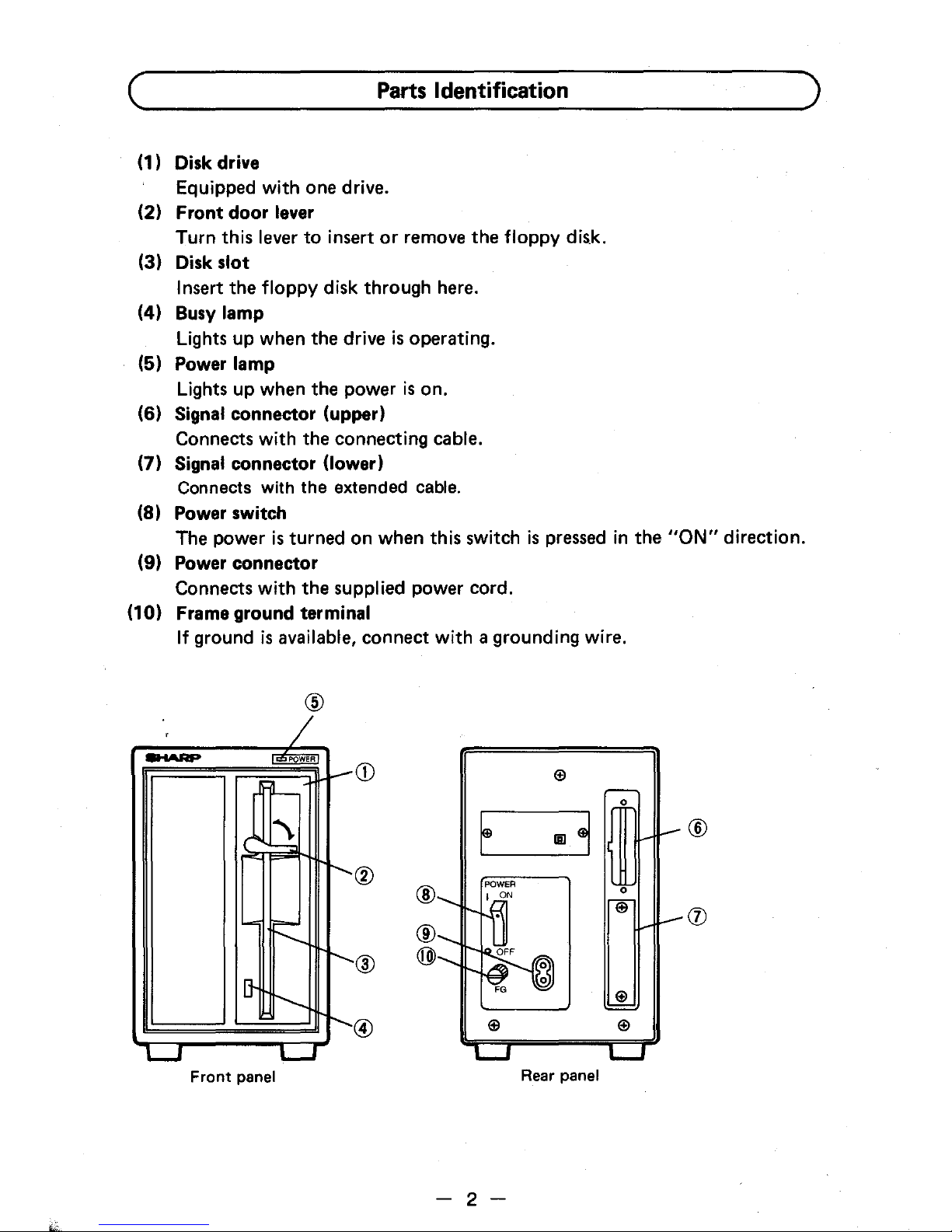
(1) Disk drive
Equipped
with
one drive.
(2)
Front
door
lever
Turn this lever
to
insert
or
remove the
floppy
dis.k.
(3) Disk
slot
Insert the
floppy
disk through here.
(4) Busy
lamp
Lights up when the drive
is
operating.
(5) Power
lamp
Lights up when the power
is
on.
(6)
Signal connector (upper)
Connects
with
the connecting cable.
(7) Signal connector (lower)
Connects with the extended cable.
(8) Power switch
The power
is
turned on when this switch
is
pressed
in the
"ON"
direction.
(9) Power connector
Connects
with
the supplied power cord.
(10) Frame ground terminal
If
ground
is
available, connect
with
a grounding wire.
@
--
Q)
El
0
E
IiI
~
CID
®
0
El
®
@
@
El
@
El
El
Front
panel
Rear panel
- 2 -
®
Page 4
Connecting
the
MZ-1
F19 Mini-Floppy
Disk
Drive
to a Computer
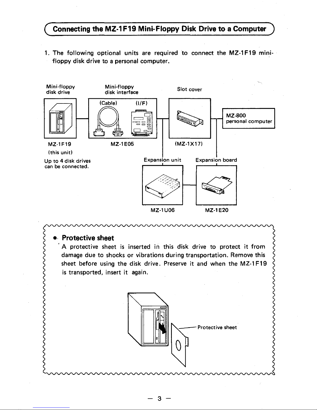
1. The following optional units are required
to
connect
the
MZ-1
F19
mini-
floppy
disk drive
to
a personal
computer.
Mini-floppy
disk
drive
MZ-1F19
(this
unit)
Up
to
4 disk drives
can
be
connected.
Mini-floppy
disk
interface
(Cable)
OfF)
o
~Cl§
===
=
M
CJ
=~
MZ-1E05
MZ-lU06
e.
Protective
sheet
Slot
cover
MZ-800
personal
computer
(MZ-1X17)
MZ-1E20
, A protective sheet
is
inserted
in
this disk drive
to
protect
it from
damage due
to
shocks
or
vibrations during transportation. Remove this
sheet before using
the
disk drive. Preserve it and when
the
MZ-1
F19
is
transported, insert it again.
- 3 -
Page 5
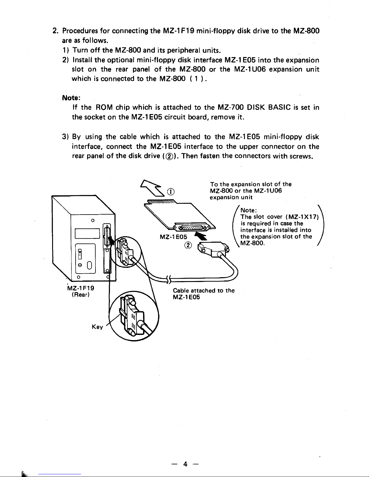
2. Procedures
for
connecting the
MZ-l
F19
mini-floppy
disk drive
to
the MZ-800
are
as
follows.
1) Turn
off
the MZ-800 and its peripheral units.
2)
Install
the
optional
mini-floppy
disk interface
MZ-l
E05
into
the expansion
slot
on
the rear panel
of
the MZ-800
or
the
MZ-l
U06 expansion
unit
which
is
connected
to
the MZ-800 ( 1
).
Note:
If
the
ROM
chip
which
is
attached
to
the MZ-700
DISK
BASIC
is
set in
the socket
on
the
MZ-l
E05
circuit
board, remove
it.
3) By using the cable which
is
attached
to
the MZ-l E05
mini-floppy
disk
interface, connect the
MZ-l
E05 interface
to
the upper connector
on
the
rear panel
of
the disk drive
(CID).
Then fasten the connectors
with
screws.
~
To
the
expansion slot
of
the
~
CD
MZ.sO~
or
th~
MZ·1U06
~
=~expanSlo(n
~:~::
)
The
slot cover (MZ-1 X 17)
is
required
in
case
the
o~
interface
is
installed into
MZ-1 E05
~
the
expansion slot
of
the
CID
MZ.sOO.
Cable attached
to
the
MZ-1E05
- 4 -
Page 6

4) When you use
the
MZ-1
F19 connecting
to
the
MZ-aOO,
be sure
to
connect
the
earth wire provided for
the
MZ-1
F19 as shown in
the
figure.
MZ·1 F19
49
~
0
E
·3
ill
MZ·800
I
ON~
OFFU
Power
-1-+---
Rear
.fi
U
@
1
{J
~
•
I
=
49
L.
I"
L....I
Rear panel
I
I
I
I
I
I
I
I
I
Bottom
~.--------------------~
Earth wire
~
Note:
. After connecting
the
mini-floppy disk drive, be sure
to
turn
on
the
disk
'drive first, and then
the
MZ-800.
When
two
or
more disk drives are con-
nected,
turn
on from
the
remotest disk drive. For example, when 4 disk
drives are connected,
turn
on
the
power switch
of
the
drive No.
4,
then
No. 3, then
No.
2, then No. 1
(as
for
the
drive numbers, refer
to
page 6).
Reverse this order when turning
off
the
power switches.
If
the
disk drives
are turned on
or
off
in
the
wrong order,
the
contents
of
the
disks may be
destroyed.
- 5 -
Page 7

c
....
____
I_n_st_8_II_in
....
g_A_dd_i_ti_o_n_81_M_in_i-_F_lo_p
....
P
....
Y_D_iS_k_D_r_iV_8_S
____
)
The optional MZ-1 C30 cable
is
provided
for
connecting additional
mini-floppy
disk drives.
Note:
The maximum number
of
disk drives which
can
be
connected
is
4.
1_
MZ-1
F19
1) Turn
off
the MZ-800 and its peripheral units.
2) Remove the screw on the
left
side
of
the additional disk drive and remove
the cover.
I.--\--
Jumper
(set
at
the
time
of
shipment)
Screw
3)
Reset
the
DRIVE
SELECT jumper on the
circuit
board according
to
the
• drive number. (The drive number
is
set
to
1 at the
time
of
shipment.)
Note:
The jumper setting pattern should
be
one
of
the
4 patterns on the
next
page.
4) Replace the cover and screw
it.
5) Remove the lower connector cover on the rear panel
of
the disk drive
which
is
already connected, and plug the connector
with
the
name label
of
the MZ-1 C30 cable
into
the lower connector. Connect the other
connector
of
the cable
to
the upper connector
of
the additional disk drive.
Fasten
both
connectors
of
the cable
with
screws.
Follow
the
same
procedures when the
third
and
fourth
disk drives are
connected.
- 6 -
Page 8

Cable attached
to
First Second
Third
Fourth
;'
MZ-'
E[BlfBtE
ill
I~R"'
~',
of
<h.d,;w
MZ-1E05
MZ-1F19
MZ-1F19
MZ-1F19
MZ-1
F19
'~
,[!
'i
'[i
Position
of
the
jumper
-
~
~
~
2_
2
00
2
00
3
00
3_
3
00
4
00
4
00
4
00
4
Drive number
2 3
4
The drive numbers are
as
shown above. Stick
the
drive No. labels
to
the drives.
(The software uses these drive numbers
to
identify each drive.)
2_
MZ-1F02
Note:
The
MZ-1
F02 must be used
as
the first and second disk drives.
1) Turn off the
MZ-800 and its peripheral units.
2) Disconnect the
cable from
the
MZ-1
F19.
3) Remove the screws
on
the left side
of
each disk drive unit
to
remove
:,
the cover.
4) Set
the
DIP switch and jumper as shown on
the
next page.
Note:
Do
not
set the DIP switch and jumper
to
the position other than
that
shown
on
the next page.
5)
Remove
the
terminator set
in
the socket located above
the
DIP switch
of
the
MZ-1
F02.
Socket
DIP switch
- 7 -
Page 9

6) Replace each cover.
7) Connect the
cable which was disconnected
at
step 2
to
the
upper con-
nector
on
the rear panel
of
the
MZ-1
F02 and fasten
the
connector with
screws.
8) Remove the
lower connector cover on
the
rear panel
of
the
MZ-1
F02.
Use
the
MZ-1
C30 cable
to
connect
the
MZ-1
F02 and
MZ-1 F 19
by
plugging the connector with the name label
of
the
cable into
the
lower
connector of the
MZ-1
F02 and the other connector into
the
upper con-
nector
of
the
MZ-1
F19. Fasten both connectors
of
the
cable with screws.
* Take the same manner
to
connect the fourth disk drive.
First
Second
Fourth
o
-Rear
panel
of
the
drive
MZ-1E05
MZ-1
F02
MZ-1 F19 MZ-1
F19
[S]
Position
of
the
DIP
---
switch
and
the
jumper
0
Drive
number
----
...
1,2
1;]0
2
00
3_
4
00
3
o
=
l
r-
:::::::
~ ~
~
-
r-
-
-
~
+-
0
2
'--
-8-
1WJO
2
00
3
00
4
4
Page 10

(~
________________
F_lo_P_p~y_D_i_Sk
__
O_p_er_a_ti_o_n
______________
~)
(1) Floppy Disk
This
floppy
disk drive
uses
a 5-1/4 (5.25) inch double-sided, double density
mini-floppy disk
for
the storage media. Its appearance
is
shown below.
It
consists
of
a magnetic sheet covered
by
a jacket and
is
called a
floppy
disk.
"-5-1/4
inch I d I b I
1-
n
ex
a e
T
D
'/
Write-protect
notch
Drive spindle hole
5-1/4
inch
1
Index
hole
0----1-
Head
window
Jacket
Drive spindle
hole.
..
When the disk
is
inserted in the drive. the drive's
spindle clamps
into
this hole
to
rotate the disk.
Head
window.
. . .
..
The read/write head comes
in
contact
with
the disk
to
read
or
write
data through this
window.
The head
is
moved
from
one track
to
another
by
a stepping
motor.
Index
hole.
. . . . .
..
This hole
is
used
for
determining the head's position
around the circumference
of
the disk.
•
It
is
recommended
that
you
buy
blank disks at the
same
store where
you
bought this
floppy
disk drive.
[Model]
MZ-6F01 (Double-sided. double-density disk. 1 pc)
- 9 -
Page 11

(2) Inserting the Floppy Disk
1.
The
floppy
disk
can
be
inserted when the
front
door
lever
is
turned
to
its
vertical position.
2. With the index
label side
(front
surface) on the
left
and the head
window
away
from
you, insert the
floppy
disk
into
the
drive. This
is
the
only
way
to
insert the
floppy
disk
for
proper operation.
(See
figure below.)
3. Gently push the disk
until
it
stops and
turn
the
front
door
lever
to
its
horizontal position. Always make sure
to
turn
the lever
to
its
horizontal
position after inserting a
floppy
disk. This drive
will
not
operate
if
the
lever
is
vertical.
Front
door
lever
(vertical
position)
Notes:
1) The lever
will
not
turn
if
the
floppy
disk
is
not
completely inserted. Do
not
forcibly
turn
the lever. Instead,
properly
reinsert the
floppy
disk
before
you
turn
the lever.
2)' Make sure
to
turn
on
the drive before inserting a
floppy
disk.
If
the
floppy
'disk
is
inserted while the power
is
off,
the
hub
hole may become damaged
and errors may
be
generated.
3) Turn
off
the power switch after
turning
the
front
door
lever
to
its vertical
position. This prevents the contents
of
the
floppy
disk
from
being
destroyed by misoperations at the
time
of
power
off.
-
10-
Page 12

(3) Write-Protect Notch
The write-protect notch
is
used
to
prevent erasure of data already written
on the floppy disk. Covering this notch with an opaque seal inhibits writing
to
the floppy disk. However,
the
floppy disk can still be read. Some floppy
disk supplied by Sharp called
the
master has this notch covered
by
a seal.
Since the notch
is
covered
to
avoid trouble due
to
erroneous operation, do
not remove it
unless necessary.
Do
not cover
the
notch with a seal
if
the
floppy disk
is
always written. The disk cannot be written
if
the notch
is
covered.
Write-protected disk
I
0
~o
t,;~_~o
__
,
(4) Data Read/Write Operation
All
that
you have
to
do with the disk drive are
to
turn on and off the power
and
to
insert and remove the floppy disk. The data read/write operation
is
controlled by the computer.
For details, refer
to
the
manual for the software being used.
-
11-
Page 13

C
_______________
F_IO~P~p~y_D_is_k_H_a_nd
__
lin_g
______________
~)
Observe
the following precautions
for
long
use
of
your
floppy
disks.
o Do
not
touch, soil,
or
scratch the recording surface (through the
head
window)
to
prevent disk errors due
to
damaged medium.
o Do
not
apply alcohol, thinner, freon,
or
other solvents
to
the magnetic
surface
or
disks.
o Do not bend
or
fold
the
floppy
disk
to
prevent damage.
o Never
place magnetized materials
(such
as
magnets) near
floppy
disks.
Mag-
netism
will
destroy the data
on a floppy
disk. For the
same
reason
keep
mag-
netic field generating equipment (such
as
moters) away
from
floppy
disks.
o Write on the index
label before attaching
it
on
floppy
disk jacket
or
use
a
soft-tipped instrument
such
as
a felt-tipped pen. The
floppy
disk may become
scratched
if
a hard-tipped instrument such
as
a pencil
or
ball-point pen
is
used.
o
Do
not place anything
or
use
paper clips on
floppy
disks
so
that
the jacket
will
not become deformed.
o Avoid eating, drinking, or smoking around the
floppy
disks.
o
Do
not
use
floppy
disks which
have
been
contaminated by spilled liquids such
as
coffee.
o
Always keep the
floppy
disk in its protective envelope and vertically in its
storage box when
not
in
use,
This
is
to
prevent problems
caused
by dust.
o Do
not
place
floppy
disks in direct sunlight
or
near heaters. The heat
will
deform the jacket and make the
floppy
disk unusable.
o
Us~
floppy
disks
within
the temperature
range
noted on the envelope. Since
the storage environment and operating environment may
differ,
leave'
the
floppy
disk(s) in the operating environment
for
30-60
minutes before using.
o
Properly insert
floppy
disks
into
the drive
unit.
o Make sure
to
turn
on the drive before inserting a
floppy
disk.
If
the
floppy
disk
is
inserted while the power
is
off,
the hub hole may become damaged
and errors may
be
generated.
-12
-
Page 14

(~
_______________
S_~
___
ifi_ca_t_ioo
__
8
________________
)
Model
Recording capacity
Number
of
tracks
Number
of
sectors
Storage medium
Power supply
Power consumption
Operating temperature
Operating
humidity
External dimensions
Weight
Accessories
MZ-1F19
320
K bytes
40
tracks/side
16 sectors/track
5-1/4 inch double-sided, double density
floppy
disk
Local voltage,
50/60 Hz
20W
10-:-35°C
20-80%
(without
condensation)
118(W) x
331
(D) x 189(H) mm
5.1
kg
Instruction Manual, drive number
seals,
power cord.
Earth wire
This apparatus complies
with
requirements
of
BS
800
and
EEC
directive
82/499/EEC.
,
Dieses
Gerat stimmt
mit
den Bedingungen der EG-Richtlinien
82/449/
EWG
uberein.
Cet appareil repond aux specifications de
la
directive
CCE
82/499/CCE
Dit
apparaat voldoet
aan
de
vereiste EEG-reglementen 82/499/EEG.
Apparatet opfylder kravene i EF direktivet
82/499/EF.
Questo apparecchio e stato
prodotto
in conform ita alle direttive
CEE
82/449/CEE.
-13-
Page 15

SHARP
CORf»ORATION
OSAKA, JAPAN
Printed
in
Japan
Gedruckt
in
Japan
Imprim6
au Japan
Stampato In Glappone
iC>
t
984
SHARP CORPORATION
4K1.00(TINSE1286ACZZ)®
 Loading...