

Page 1
INSTRUCTION
MANUAL
MANUEL
D'UTILlSATION
BEDIENUNGSANLEITUNG
ISTRUZIONI
PER
L'USO
Page 2
English
...•..•...•...•.............•........
2 - 5
German
...•.•••.•.•...•...•................
6 - 9
French
........•••..........•..••.........
10-
13
Italian
...••.•••...........................
14 -
17
r-------FOR
U.K.
CUSTOMERS--------,
IMPORTANT
The wires
in
this
mains
lead
are
coloured in accordance with the following code:
GREEN·AND·YELLOW: Earth
BLUE: Neutral
BROWN: Live
As
the colours
of
the wires in the mains
lead
of
this apparatus may
not
correspond
with
the coloured markings identifying the terminals in your plug proceed
as
follows.
The
wire which
is
coloured GREEN·AND·YELLOW must
be
connected
to
the
terminal in the
plug which
is
marked by the letter E or by the safety earth
symbol~
or coloured
green
or
green·and·yellow.
The
wire which
is
coloured BLUE must
be
connected
to
the terminal which
is
marked
with
the letter N or coloured black.
The wire which
is
coloured
BROWN
must
be
connected
to
the terminal which
is
marked with the letter L or coloured
red.
Ensure
that your equipment
is
connected correctly·if you
are
in any doubt consult
a
qualified electrician.
"WARNING: THIS APPARATUS MUST
BE
EARTHED"
-1-
Page 3

Introduction
Thank
you
for
buying Sharp's
color
display MZ·
1019.
Please
read
this manual carefully
for
proper
use.
Also,
be
sure
to
keep this manual
for
later
use.
This manual should
be
helpful during
use
or when
problems arise.
~lGBI
direct
drive system.
• Practical
use
2000 character display.
Contents
PAGE
Features
. . . . . . . . . . . . . . . . . . . . . .
..
2
Precautions . . . . . . . . . . . . . . . . . . . .
..
2
Names and functions
of
each
part
.......
3
Input
signals
.....................
4
Connection . . . . . . . . . . . . . . . . . . . .
..
5
Specifications
....................
5
• 16
color
display (black, blue, green, cyan, red, magenta, yellow, white, gray, light blue,
light
green, light cyan,
light
red,
light
magenta,
light
yellow, high intensity
white)
• 58W
low
power consumption design.
• Since this
unit
contains precision parts such
as
ICs,
do
not
place
it
in
a location exposed
to
dust,
humidity
or
sudden
changes
in
temperature.
• When disconnecting the power plug, always pull the plug itself and
not
the power cord. Also,
turn
off
the
power switch before pulling the plug.
•
When
not
in
use
for
long periods
of
time, disconnect the power cord
from
the power
outlet
for
safety.
•
Be
especially careful when handling the CRT. Do
not
hit
or
drop
it.
Do
not
turn
it
on its side or back. Do
not
apply mechanical shock
or
vibration. Such
abuse
may become the source
of
trouble later.
•
Do
not
place anything on this
unit,
as
doing
so
may deform the cabinet.
• Never open the rear cover. There are
several
high voltage parts located
within
this
unit.
Do
not
touch anything
;nside this
unit
as
there is the danger
of
electric shock.
'-"Do
not
place
anything
magnetic such electric clocks near this
unit.
The magnetism may
cause
the
screen
to
flicker.
•
Do
not
clean this
unit
with
any volatile
liquid
such
as
alcohol, benzine
or
thinner.
Use
of
a volatile
liquid
may
damage this
unit.
Always
use
a soft,
dry
cloth
when wiping this
unit.
For
cleaning
of
the internal parts, consult
your
dealer.
• There
may
be
times when a slight electric shock
is
felt
when
CRT
screen
is
touched. This
is
because
the
CRT
screen
has
a static
electricity
charge which does
not
affect
the human body.
•
To
display a video picture on this
unit,
connect
it
with
a computer using the connecting cable. This
unit
cannot
be
used alone.
-2-
Page 4
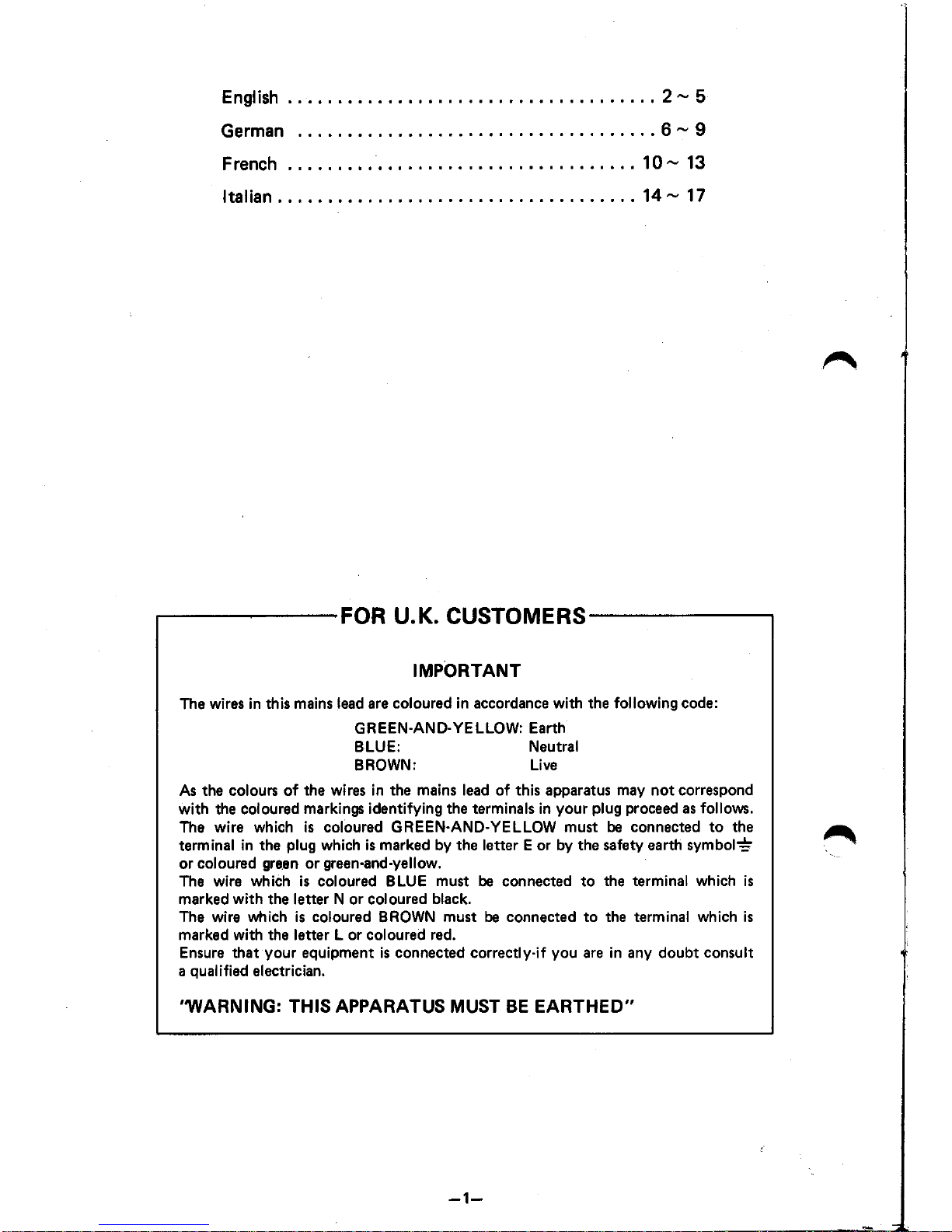
Names and
H-HOLD--------lUJ..:~:::;::;~~
(horizontal
hold
adjustment)
Turn
this knob
to
edjust the pic-
ture when the picture moves
sideways or disappears.
V-SIZE
----------11-11--
___
......,
(vertical
size
adjustment)
Turn
this
knob
to
adjust the
picture
when
the height
is
stretched
or
shrunk.
V-HOLD.~=:~~~~----~~~~~~t:~~~~!!
Turn and adjust this
knob
when
the picture moves up
or
down
and
is
not
still,
or
when parts
of
the screen overlap.
BRIGHTNESS--------------~
Turning
this knob varies the
brightness
of
the picture.
•
Turning
it clockwise
brightness the picture.
•
Turning
it
counterclockwise
darkness the picture.
Power cord (Accessories)
__________________
...J
-3-
Power
indicator
lamp
~I---
Power switch
ON:
Push
to
turn
on (power
indicator
lamp
I ights up)
Push
again
to
turn
off
(power indicator
lamp
goes
out)
SIGNAL
INPUT
CONNECTOR
As
shown in the figure, the
signal
input
cable
from
the
computer
is
connected to the
signal input connector.
Signal
input
~
connector11
,:R~~'
,:R~
®
~~.~.
~,I!j
Signal
input
cable
Page 5

1.
Input signals
a. Video signal separate R.G.B.1. System
TTL level positive polarity
TTL
level
positive polarity
TTL level negative polarity
TTL level negative polarity
b. Intensity signal
c. H·hold signal
d. V-hold signal
2. Timing charts
of
the video signal (typical example)
a. Relation between the video signal
and
the H-hold signal.
(unit:
~IS)
Data blank interval Data interval
;.---
27.97 ai_ 36.09
al
Video signal 1L--'
__
---I!IIIIIIII
~
11111111111
~:
__
H-hold signal
---'1
I I // I
r-
I---l I i
~
,
'14.43B..I
~
___
_
~
~
b. Relation between
the
video signal
and
the V-hold signal.
(unit:
ms)
Data
blank
interval
Data interval
1-----7.17
alol
12.B1
,I
VideOSignal~L-_--IIIIIIIIII'IIIIIIIIIIII~;
_
V-hold signal
---"""U
! It i
U-
, ,
4.09B--:
I ,
~
~
- Signal input connector
VTh~
relation between each pin
of
the 8-pin
connector
and each rnput signal
is
as
follows.
PIN
ASSIGNMENT
1 Intensity
2
Video input I Red)
3
Video input (Green)
4 Video input (Blue)
5
Ground
~
6 Ground
7
H-Orive
B
V-Drive
-4-
Page 6
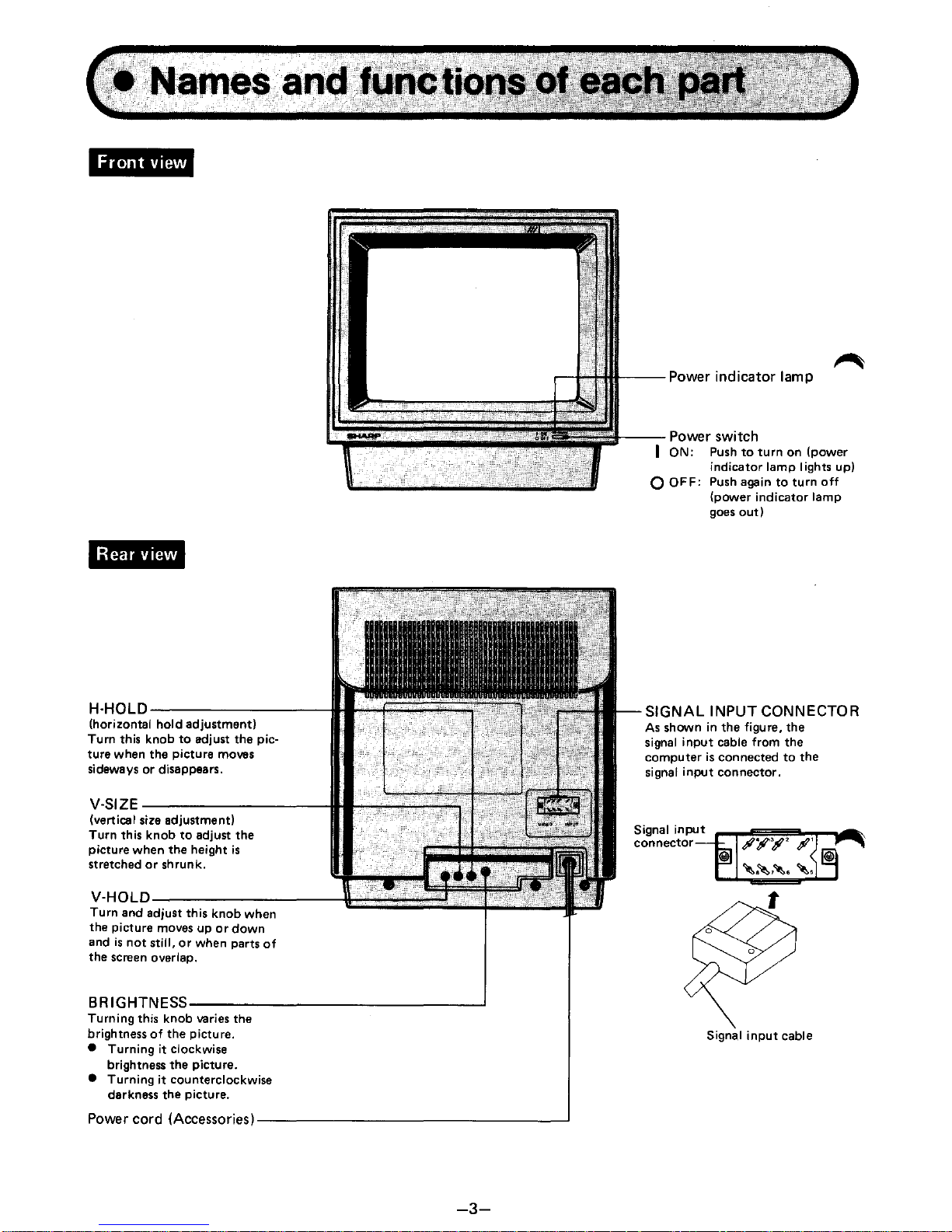
1.
Before connection,
turn
off
the power
of
both
the
computer
and the
CRT
display.
2.
Attach
the DI N connector
of
the accompanying connector cable
to
the RGB connector on the back
of
the
computer and the square connector on the other end
to
the video
input
terminal on the back
of
the display.
(See
Connection diagram)
Model name
Product name
CRT
Input
signal
Deflection frequency
Display time
Display
colors
Resolution
Power requi rements
External dimensions
Weight
Accessori
es
(MZ·800
rear view)
MZ·1D19
Color display
14 inch,
900 deflection
(MZ·1D19
rear view)
Video
signal separate R.G.B.1. system
ITL
Level positive polarity.
Intensity
signal
TTL
level positive
polarity
H·hold signal
TTL
level negative
polarity
~
V-hold signal
TTL
level negative
polarity
Horizontal 15.6 kHz, Vertical 50.04 Hz
Horizontal
36.09
/J-s,
Vertical 12.81 ms
16
color
display (black, blue, green, cyan, red, magenta, yellow, white, gray,
light blue,
light
green,
light
cyan,
light
red,
light
magenta,
light
yellow,
high
intensity
white)
Horizontal
480
dots, Vertical
240
lines (non-interlaced)
AC
Local voltage (2201240V),
50
Hz, 58 W
Width 364 mm x Depth
425
mm x Height
370
mm (Max.)
13.5 kg
1 instruction
manual, 1
AC
power cord, 1 Connecting cable
These
specifications
are
subject
to
change
without
notice
for
improvements.
-5-
Page 7

Einleitung
Wir
freuen uns, daB Sie sich
zum
Kauf des Farbbild-
schirm-Anzeigegeriites
MZ-1
D19
von
Sharp
ent-
schieden haben_ Fur den richtigen Gebrauch lesen
Sie diese Bedienungsanleitung
bitte
sorgfiiltig durch_
Fur spiitere Bezugnahme die Bedienungsanleitung
sorgfiiltig aufbewahren. Diese Bedienungshinweise
sind
nutzlich zum Gebrauch
nud
beim
Auftreten
von
eventuellen Betriebssorungen.
• RGBI-Direktantriebs-System.
• Anzeige von
2000
Zeichen effektiv
Inhalt SEITE
Ausstattungsmerkmale . . . . . . . . . . . . .
..
6
VorsichtsmaBnahmen
...............
6
Bezeichnung
und
Funktionen
der
einzelnen Teile
...........
. . . .
..
7
Eingangssignale
...................
8
AnschluBweise
....................
9
Technische Daten . . . . . . . . . . . . . . . .
..
9
• Anzeige
in
16 Farben (schwarz, blau, griin, cyan, rot, magenta, gelb, weiB, grau, hellolau, hellgrun, hellcyan,
hell rot, hellmagenta, hellgelb,
intensiv weiB)
•
Geringe Leistungsaufnahme (58W).
• Dieses Geriit enthiilt hochpriizise verarbeitete Bauteile wir
ICs
usw. Daher das Geriit
nicht
an Orten aufstellen,
wo es
plotzlichen
Temperaturschwankungen,
Staub
oder
hoher
Feuchtigkeit ausgesetzt ist.
• Beim Ziehen des Netzsteckers stets
am
Stecker,
nicht am Kabel anfassen. Den Stecker nach Ausschalten des
Geriites ziehen.
• Wenn das Geriit liingere
Zeit
nicht
verwendet werden 5011,
zieht
man
aus Sicherheitsgrunden den Stecker.
• Das Geriit nicht anstoBen bzw. fallen lassen. Desgleichen das Geriit nicht
auf
die Seite oder die Ruckseite legen.
Die Einwirkung mechanischer StoBe bzw. Vibrationen vermeiden. Andernfalls
konnen
dadurch spiitere
Betriebsstorungen verursacht werden. Bei der Handhabung der
Bildrohre
mit
besonderer Vorsicht vorgehen.
• Keine Gegenstiinde
auf
dem Geriit ablegen. Andernfalls
konnte
das Gehiiuse
verformt
werden.
10..
.JAuf keinen Fall die Ruckwand offnen. Im Geriit befinden sich mehrere Hochspannung-fuhrende Teile, die zu
"'beruhren
iiuBerst gefiihrlich ist.
Auf
keinen Fall Teile
im
inneren dieses Geriites beruhren, da die Gefahr eines
elektrischen Schlages gegeben ist.
• Keine magnetischen Gegenstiinde, wie z.B. die magneten von elektrischen Uhren
in
die Niihe dieses Geriites
bringen.
Andernfalls kann
der
Magnetismus Bildschirmflackern verursachen.
• Dieses Geriit
nicht
mit
chemischen Reinigern. Alkohol. Benzin
oder
Farbverfunner reinigen. Zum Reinigen
stets ein weiches
trockenes
Tuch verwenden. Durch den Gebrauch von chemischen Reinigen wird die Ober-
fliiche
des Geriites angegriffen. Zum Reinigen innerer Teile wend
et
man
sich an
den
Hiindler.
•
Bei Beruhren der Bildschirmoberfliiche spurt
man
eine leichte elektrische Wirkung. Dieses Phiinomen wird
durch
die elektrostatische Ladung des Bildschirms ausgelost, es stellt keine Gefahr fur den menschlichen
Korper dar.
• Um eine Bildwiedergabe zu bewirken ist der AnschluB dieses Geriites
mit
dem mitgelieferten AnschluBkabel an
einen
Computer
erforderlich. Dieses Geriit allein kann
nicht
verwendet werden.
-6-
Page 8

'ii.!n;hWU
';1.'
ZEILENEINSTELLUNG
(H-HOLD)
-------
(Zei lenfang-E instell u
ng)
Zur
Einstellung
des
Bildes, wenn
das
Bild
seitwiirts wegliiuft, bzw.
verschwindet. .
BI
LDFANG (V-HOLD)
___
_
Wenn
das
Bild nach oben oder
unten
durchliiuft,
oder wenn der
Bildschirme in iiberlapptes
Bild
anzeigt,
nimmt
man die
Einstellung
mit
diesem Regler vor.
V-SIZE
__
---:-:------t::==::::!..;.:~~~~I_JJ
(Teilbild-H6henregler)
Zur
Einstellung
des
Bildes, wenn
die
Bildh6he gedehnt oder
gastaucht ist.
HELLlGKEITSREGLEM
__________
---'
(BRIGHTNESS)
Zur
Veriinderung der Bildhelligkeit
verwendet man diesen Regler.
•
Durch Drehen
im
Uhrzeigersinn
nimmt
die Helligkeit zu.
• Durch Drehen
gagan
den Uhr-
zeigarsinn
nimmt
die Helligkeit
ab.
Netzkabel
(ZubeI10r)------'
-7-
Einschalt-Anzeige
Zum Einschalten drucken.
(Die Einschalt-Anzeige
leuchtet
auf)
Zum Ausschalten die Taste
nochmals d riic
ken
. (Die
Einschalt-Anzeige erlischt).
SIGNALEI NGANGSBUCHSE
Wie aus der zeichnung ersichtlich,
wird
das
Signaleingangskabel vom
Computer an die
Signaleingangsbu-
chse angeschlossen.
Signaleingangsbuchsenkabel
Page 9

1. E ingangssignale
a. Videosignal separates R.G.B.1. System
TTL-Pegel, positive Polung
TTL-Pegel,
positive Polung
TTL-Pegel,
negative Polung
TTL-Pegel,
negative Polung
b. I ntensitiitssignal
c. H·hold signal (Zeileneinstellsignal)
d. V-hold signal (Bildfang-Signal)
2. Impulsiibersicht
des
Videosignals
(typisches
Beispiel)
a. Verhiiltnis zwischen Videosignal und Zeileneinstell-signal.
IEintieit:
jJ.S)
Leerstellen-Intervall Oaten-I ntervall
I+-----
27.97
_I_
36.09
_I
I I I
Videosignal
1'-------1111
~IIIIIIIIIIII
~_-
Zeileneinstell-5ignal ---'W !
iI
i
W-
I I 14,43B"":
~
___
_
~
~
b. Verhiiltnis zwischen Videosignal und bildfang-Signal.
IEinheit:
ms) Leerstellen-I ntervall
Oaten-I ntervall
!----7.17
_101
12.B1
_I
Videosignal
~'----------i!
IIIIIIII~
111111111111
!.....-:
_
Bildfang-5ignal---...,U
!
11
j
U-
I I 4.09B.......: I I
~
~
~s
ignaleingangs-steckverbinder
....... Zwischen den
Stiften
des 8-Pin Steckers und den einzelnen Eingangssignalen besteht folgende Beziehung:
STI FTBE LEG UNG
1 Intensitat
2
Videoeingang I Rot)
3
Videoeingang I Griin)
4 Videoeingang IBlau)
5
Erdung
6 Erdung
7
H-O
B V·O
-8-
Page 10

1.
Vor
dem AnschluB sowohl
den
computer
als
auch
das
Bildschirm-Anzeigegerat ausschalten.
2.
Den DIN-Stecker
des
mitgelieferten DIN-Verbindungskabels
an
den RGB-AnschluB an der Rlickseite
des
Computers, den rechteckigen Stecker
am
anderen kabelende
an
den videoeingang
an
der Rlickseite
des
Bildschirms anschlieBen. (siehe Zeichnung)
(MZ-800, Riickseite)
(MZ-1D19,
Riickseite)
Modellname
Produktnama
Bildriihre
Eingangssignal
Ablenkfrequenz
Anzeigezeit
Anzeigefarben
Aufliisung
Stromversorgung
AuBere Abmessungen
Gewicht
Zubehiir
MZ-1D19
Farbbildschirm-Anzeigegerat
Hochaufliisende 14-Zoll-Farbbildriihre,
900 Ablenkung
Videosignal,
separates R.G.B.1. System, TTL-Pegel, positive polung
Intensitatssignal TTL-Pegel,
positive Polung
Zeileneinstel'-Signal, TTL-Pegel,
negative Polung
Bildfang-Signal, TTL-Pegel,
negative polung
Horizontal 15,6 kHz, vertikal 50,04
Hz
Horizontal 36,09
/J.S,
vertikal 12,81
ms
16
Farben (schwarz, blau, grlin, cyan, rot, magenta, gelb, weiB, grau,
helliilau, hellgrlin, hellcyan, hell
rot,
hell magenta, hellgelb, intensiv weiB)
Horizontal
480
Bildpunkte, vertikal 240 Zeilen (ohne Zeilensprung)
Regionale
Netzspannung (220/240Vl. 50 Hz, 58 W
364 (B) x
425
(T) x
370
(H) mm (Max.)
13,5
kg
1 Bedienungassnleitung, 1 netzkabel, 1 AnschluBkabel
Anderungen der technischen Daten vorbehalten.
-9-
Page 11

Introduction
Nous vous felicitons
pour
I'
achat
de
cet
affichage
couleur MZ-1D19 Sharp. Afin d'utiliser correctement
cet
affichage couleur, veuillez lire ce mode
d'emploi tres attentivement.
Ce
mode d'emploi sera
d'une
aide precieuse
pendant
I'utilisation
ou
en cas de
probleme.
~Svsteme
cl
commande directe RGBI.
•
Affichage de
2000
caracteres d'utilisation pratique.
Table del matiltre. PAGE
Caracteristiques . . . . . . . . . . . . . . . .
..
10
Precautions . . . . . . . . . . . . . . . . . . .
..
10
Designation
et
fonction de chaque partie
..
11
Signaux d'entn!e . . . . . . . . . . . . . . . .
..
12
Raccordement . . . . . . . . . . . . . . . . .
..
13
Fiche technique . . . . . . . . . . . . . . . .
..
13
• Affichage 16 couleurs (noir, bleu, vert, bleu-vert, rouge, magenta, jaune, blanc, gris, bleu clair, vert clair, bleuvert clair, rouge clair, magenta clair, jaune clair, blanc intense)
• Conception
cl
faible consommation d'energie (58 W).
• Cet appareil
comportant
des composants de precision, tels
que
des circuits integres (lC),
il
ne doit pas
etre
place dans un endroit sujet
cl
des variations brusques de temperature,
ni
dans un endroit humide ou pou-
ssiereux.
• Pour debrancher
le
cordon d'alimentation, toujours tenir
la
fiche
et
non pas
le
cordon
proprement dit.
De
plus,
la
fiche ne
doit
etre
debranchee qu'apn!s avoir coupe I'alimentation.
•
Lorsque I 'apparei I nest pas utilise
pendant
une periode prolongee, debrancher
le
cordon d'alimentation de
la
prise secteur par mesure de securite.
•
Ne pas heurter
cet
appareil
et
ne pas
le
laisser tomber.
De
plus,
il
ne
doit
pas etre couche sur
le
cote
ni
a
I'arriere.
11
ne
do
it pas etre soumis
cl
des chocs mecaniques
ni
a des vibrations. Cela pourrait a
la
longue etre
une source
de
probhlmes. D'une maniare generale, I'ecran
cathodique
doit
etre manipule avec soin.
~e
rien placer sur
cet
appareil, cela pourrait deformer son boitier.
•
Ne
jamais ouvrir
le
capot
arriere. Cet appareil
comporte
plusieurs pieces haute tension pouvant etre dan-
gereuses.
Ne
rien toucher
cl
l'interieur de
cet
appareil car
il
va
un danger d'electrocution.
•
Ne
pas placer d'objets magnetiques, tels qu'aimants ou horloges electriques, a proximite de
cet"
appareil.
Le
magnetisme affecterait son
fonctionnement
et
provoquerait un scintillement de I'ecran.
•
Ne pas
nettover
cet
appareil avec un
produit
volatile, tel que de I'alcool, de
la
benzine ou
du
diluanti Toujours
utiliser un chiffon
doux
et
sec
pour
essuver
ses
surfaces. L'emploi dun liquide volatile
peut
endommager
rappareil. Pour
le
nettovage de I'interieur,
se
renseigner aupres
du
depositaire.
• On
peut
parfois ressentir un leger
effet
electrique lorsuqe I'on touche
la
surface de I'ecran cathodique. Cela
provient de
la
charge d'electricite statique de I'ecran
et
n'a aucun effect sur
le
corps humain.
• Pour
obtenir
une image video avec
cet
appareil,
le
raccorder a un ordinateur au moven du cable de reccorde-
ment
fourni. Cet appareil ne
peut
pas etre utilise
tout
seul.
-10-
Page 12

'im,hi'"
SYNCHRONISATION
HORIZONTALE
(H-HOLD)----lI.~~..;;;.;..;;;.;...::::..:,
(n3glage
de
la synchronisation
horizontale)
Agir sur
ca
couton
pour
regler
I'image lorsqu'elle
se
deplace
lateralement
DU
disparait.
HAUTEUR
VERTICALE----lHI-,.---.---....
(r.glage de la
hauteur
verticalel
Agir sur ca
bouton
poru ragler
"image lorsque la hauteur
est
allongee
OU rI!trl!cie.
STABI LITE VE RT! CALE
----\C::====-
......
./-o
..............
.:..aIu
(V-HOLD)
Ajuster
ce
bouton
en
le
tournant
lorsque I'image
se
deplace
vers
le
haut
ou
vers le
bas
et n'est
pas
immobile. DU lorsque
des
parties
de
I'image
se
recouvrent.
LUMINOSITE
(BRIGHTNF~!;;\--------....J
La luminosite de I'image paut etre
modifiee
en
tournant
ca
bouton.
• L'image s'eclaircit lorsque le
bouton est tourne dans le sens
des
aiguilles
d'une
montre.
• L'image s'assombrit lorsque le
bouton est tourne dans le sens
contraire
des
aiguilles d'u
ne
montre.
Cordon d'ali.TI"nt
••
tirln
___
.J
(Accessoires)
-11-
Indicateur
d'alimentation
~.
I nterrupteur
d'
alimentation
ON:
Appuyer
pour
enclencher
(L'indicateur d'alimentation
S'allumel.
Appuyer
une nouvelle fois
pou r declencher
(L'indicateur
d'alimentation
S'eteint).
CONNECTEUR D'ENTREE
DU
SIGNAL
Tel
qu'illustre,
le cable
d'entn3e
du
signal provenant
de I'ordinateur
est
branch6 au
connecteur
d'entree du signal.
Connecteur
d'entree du
signal
Cable
d'
entree
du signal
Page 13

1. Signaux d'entree
a. Signal video
b. Signal d'intensite
c.
Signal
de
stabil ite-H
d. Signal
de
stabilite-V
Niveau
TTL, polarite positive
Niveau
TTL, polarite positive
Niveau
TTL, polarite negative
Niveau
TTL, polarite negative
2. Diagramme
des
temps du
signal
video (exemple type)
a. Relation entre
le
signal video
et
le
signal de stabilite horizontale
(H)
(Unite:
/-Is)
Intervalle vierge de donnees Intervalle de donnees
I+--
27,97
..
~
36,09
_I
I I I
Signal video
~L...-_~'
11111111
~'IIIII
"" "
111----
Signal de stabilite-H ---"W !
/I
i
~
I I
14438
I I I
~~
~
b. Relation entre le signal video
et
le
signal
de
stabilite verticale (V)
(Unite:
ms)
I
nterval
le vierge de donnees Intervalle de donnees
1----7,17
_If
12,81
_I
Signal video
~'--------flllllllll'
11111111111111--;
_
Signal de stabilite-V
-----,U
!
if
i W
I I
4,098---:
I I
~
~
3. Connecteur d'entree de
signal
Va
relation
entre
chaque broche du
connecteur
a 8 broches
et
chaque
signal
d'entree
est
comme
suit.
ASSIGNEMENT
DE BROCHE
1 Intensite
2 Entree video (Rouge)
3 Entree video
(Vert)
4 Entree video (Bleu)
5
Terre
6 Terre
7
H-D
8
V-D
-12-
Page 14

1.
Avant
de
proceder
au
raccordement couper I'alimentation
de
I'ordinateur et
de
lecran cathodique.
2.
Fixer
le
connecteur
DIN
du cable
de
connexion inclus
au
connecteur
RGB
situe sur
la
face
arriere
de
I'ordina-
teur et
le
connecteur carre a I'autre extremite a
la
borne d'entree a I'arriere
de
I'afficheur.
(Voir
schema).
(MZ-800,
face
a rrllre) (MZ-1D19, face arrillre)
Fiche-
..
..an.
Designation
du
modele
Appellation du
produit
lam
pe
a reyons cathodiques
Signal d'entree
Frequence
de
deviation
Duree d'affichage
Couleurs affichees
Resolution
Alimentation
Dimensions exterieures
Poids
Accessoi
res
MZ-1D19
Affichage couleur
lampe
couleur
14",
deviation 90°
System
R.G.B.I.
separe
du
signal
video, niveau
TTl,
polarite positive.
Signal d'intensite Niveau
TTl,
polarite positive.
Signal de stabilite-H: Signal
TTl,
polarite negative
Signal
de
stabilite-V: Signal
TTl,
polarite negative
Horizontale:
15,6 kHz
Verticale:
50,04
Hz
Horizontale: 36,09
jJ.S
Verticale: 12,81
ms
16 couleurs, (noir, bleu, vert, bleu-vert, rouge, magenta, jaune, blanc, gris, bleu
clair, vert clair, bleu-vert clair, rouge clair, magentaclair, jaune clair, blanc
intense)
Horizontale:
480
points
Verticale:
240
lignes
(sans
entrelacement)
Tension
locale
(220/240V).
50 Hz, 58 W
364
(l)
x 425
(P) x 370
(H) mm (Max.)
13,5 kg
1 Mode
d'emploi, 1 Cordon d'alimentation, 1 Cable
de
raccordement
les
specifications sont sujettes a modification
sans
pniavis pour amelioration du
produit.
-13-
Page 15

Introduzione
Congratulazioni per
I'ottimo
acquisto
delle
schermo a
colori
MZ-1019
della
Sharp_
AI
fine di usarlo cor-
rettamente,
si
raccomanda
di
leggere attentamente
questo
manuale_
Esso
vi
san!
inoltre
de
aiuto
nella
soluzione
di
eventual i
difficolta.
~istema
RGBI
ad
accoppiamento
diretto
con.
Indice PAGINA
Caratteristiche . . . . . . . . . . . . . . . . .
..
14
Precauzioni . . . . . . . . . . . . . . . . . . .
..
14
Oesignazione·e funzione delle parti
.....
15
Segnali
di
ingresso . . . . . . . . . . . . . . .
..
16
Collegamento. . . . . . . . . . . . . . . . . .
..
17
Oati tecnici . . . . . . . . . . . . . . . . . . .
..
17
• Schermo pratico da usare, con una capacitll
di
2000 caratteri.
• Schermo a 16 colori (nero, blu, verde, ciano, rosso, magenta, giallo, bianco, gnglo, azzurro chiaro,
verde
chiaro, ciano chiaro,
rosso
chiaro, magenta chiaro, giallo chiaro, bianco
ad
alta intensitll).
• Consumo
energetico
limitato
(58
W).
• Questo apparecchio contiene parti di elevata precisione (come per esempio
circuiti
integrati). per cui non
deve
essere
installato in luoghi soggetti a
importanti
cambiamenti
di
temperatura, polverosi 0
molto
umidi.
•
Per
scollegare il cavo
di
alimentazione, afferrarne sempre bene
la
spina; non tirare
iI
cavo
stesso.
I noltre, prima
di
scollegarlo
da
rete, spegnerlo.
• Quando non
si
intende
usare
iI
video per lunghi periodi
di
tempo
si
raccomanda di scollegare il cavo di cor-
rente.
• Non sottomettere il video a colpi. Non voltarlo
ne
sui
lato,
ne
all'insu. Non sottometterlo a
scosse
0 vibrazioni,
per evitare possibili danni. Trattare il video CRT con cura.
• Non disporre
nessun
oggetto sopra il video. Cib potrebbe causare deformazioni dell'involucro.
\..
.JNon
togliere mai
iI
coperchio posteriore. Parecchie parti interne sono
sotto
alta tensione, e il
contatto
con
esse
-..rpotrebbe
essere
causa
di
scosse
elettriche.
• Non avvicinare magneti (come per esempio il magnete di un orologio elettrico)
al
video. Cia potrebbe
causa
re
un
tremolio
nello schermo.
• Non pulire il video usando liquidi volatili quali alcool, benzina 0 diluenti. Usare sempre
uno
strofinaccio
mordibo
e asciutto. L'uso di
liquidi
volatili potrebbe danneggiare
la
rifinitura.
Per
quanto riguarda
la
pulizia
delle parti interne, rivolgersi
al
proprio
vivenditore.
• A volte, e possibile che toccando
10
schermo
si
abbia
la
sensazione di sentire I'elettricita. Questo e dovuto
effettivamente all'elettricita statica caricatasi sullo schermo,
la
quale non e comunque dannosa all'organismo
umano.
•
Per
riprodurre delle immagini
su
questo video, collegarlo
ad
un computer facendo
usa
dell'apposito cavo
fornito.
II video non
pUG
essere
usato come unita a
se
stante.
-14-
Page 16

~--f--+-fll----Indicatore
di
funzionamento
I~~_~~~~=~~~~~ii~~~;"':"!~--,
nterruttore
di
corrente
[ ON (accesso); Premere
per
accendere
(I'indicatore
di
funzionamento
si
accendel.
~
COMANDO
01
ALLlNEAMENTO
ORIZZONTALE (H-HOLD)
-~II=F=~~~=;:::Y
(regolazione del
tracciamenta
orizzontale)
Far girare quests manopola per
regolare fermare I'immagine
quando
si
sposta sui lati osparisce.
V-SIZE--------H...---~n
(regolazione verticale delle
forme)
Far girare questa manopola per
regolare
I'immagine
quarido
le
forme appaiono allungate 0
accorciate.
COMANDO
01
ALLlNE
VERTICALE (V-HOLD)
Toccard questo
comando
quando
I'immagins sfugge verso
I'alto
0
if
basso, 0
quando
le immagini
si
sovrappongono.
LUMINOSITA
(BRIGHTNESS)--------'
Girando
questa
manopola
si
regola
la
luminosita
deWim-
magine .
• Girare in
sensa
orario per
rendere I'immagine
piu
luminosa .
• Girare
in
sensa
antiorario
per
rendere
I'immagine piu oscura.
Cavo
di
alimentazione
(Accessori)
-15-
o
OFF
(spento); premere
di
nuovo
per spegnere
if
video
(l'indicatore
di
funzionamento
si
spegne).
.:-.--HlI----
PRESA
DEL
SEGNALE
01
INGRESSO
Come
illustrato nella figure,
la
cavo di ingresso del segnale dal
computer
viene collegato alia
presa del segnale di ingresso.
Presa del
segnale
di
ingresso
Cavo del segnale
di ingresso
Page 17

1.
Segnali di ingresso
a.
Segnale
video
b.
Segnale
di intensita
c.
Segnale
H-hold
d.
Segnale
V-hold
Polarita
positiva livello
TTL
Polarita positiva livello
TTL
Polarita negativa livello
TTL
Polarita negativa livello
TTL
2.
Tabelle di sincronizzazione del segnale video (esempio tipico)
a.
Relazione tra
iI
segnale
video e il
segnale
H-hold (unita:
/Js)
I
ntervallo
senza
d_ti
Interv_llo
con
d_ti
~27,97
11'
36,09
_I
I I I
Segnale
video
---1
..
---------11
11
I
!
,IIIIIIIIW
11I1
1111111
1
1--
__
Segn_le
H-hold
---"W !
if
i
~
I I
14438
I I I
~~
~
b. Relazione tra il
segnale
video e
iI
segnale
V-hold (Unita:
/Js)
I
ntervallo
senza
dati
I
ntervallo
con
dati
.
1---7,17
"'" 12,81
1I
Segnale video
~L.-----f!1
1111111I/~/f'11111111111I1
~:
__
Segn_le
V-hold
-----,
r----+----/
..
/-------..,.,....-
W:
i W
I I
4,098--':
I I
~ ~
Presa
di
ingresso del segnale
~La
ralazione tra ognuno degli 8 spilli della
presa
ed
ogni
segnale
di ingresso e come
segue.
SPI
LLO
1 I
ntensita
2
Ingresso
video
(Rosso)
3
Ingresso video (Verde)
4
I ngresso video (Blu)
5 Messa a
terra
6 M essa a
terra
7 H-D
8
V-D
-16-
Page 18

1.
Prima
di
esequire il collegamento, spegnere siail computer cheil video.
2.
Collegare il connettore DIN a un capo del cavo in dotazione
al
connettore RGB
sui
retro del computer,
ed
il
connettore quadrato, suWaltro capo del cavo, al terminale
di
ingresso video,
sui
retro delle schermo.
(Vedere
schema
collegamenti)
(Retro dell'MZ·800)
(Retro dell'MZ·1D19)
( ./Dati
tecni~,
Modello
Designazione del
prodotto
Tubo CRT
Segnale
di
ingresso
Frequenza
di
deflessione
Tempo
di
visualizzazione
Colori delle
schermo
Risoluzione
Alimentazione
Dimensioni esterne
Peso
Accessori
MZ·1D19
Schermo a colori
Tubo
CRT
di
14
pollici,
90° deflessione
Segnale
video, a sistema R.G.B.1. separato, livello
TTL,
polarita positiva
Segnale
di
intensita Polarita positiva livello
TTL
Segnale
H·hold, polarita negativa livello
TTL
Segnale
V·hold, polarita negativa livello
TTL
orizzontale 15,6 kHz, verticale 50,04 Hz
36,09
MS
orizzontalmente e 12,81
ms
verticalmente
Schermo a 16 colori (nero, blu, verde, ciano,
rosso,
magenta, gizllo, bianco,
grigio, azzurro chiaro, verde chiaro, ciano chiaro, rosso chiaro, magenta chiaro,
giallo chiaro, bianco
ad
alta intensita).
rozzontale
480
punti,
verticale 240 righte (non intrecciate)
Tensione
locale (220/240VI. 50 Hz, 58 W
larghezza
364
mm x
profondita
425
mm
x altezza
370
mm (Max.)
13,5
kg
manuale delle istruzioni, 1 cavo
di
alimentazione, 1 Cavo
di
collegamento
Dati tecnici soggetti a modifiche
senza
preawiso, per eventuali miglioramenti.
-17-
Page 19

This apparatus complies with requirements of
BS
800
and
EEC
directive
82/499/EEC.
Dieses
Geriit stimmt
mit
den Bedingungen der EG-Richtlinien
82/499/
EWG
iiberein.
Cet
appareil repond aux specifications de
la
directive
CCE
82/499/CCE.
Dit apparaat
voldoet aan de vereiste EEG-reglementen 82/499/EEG.
Apparatet
opfylder kravene i EF direktivet 82/499/EF.
Questo apparecchio
~
stato
prodotto
in
conform ita alle direttive CEE
82/499/CEE.
Page 20

SHARP CORPORATION
OSAKA, JAPAN
Printed in Japan
Gedruckt
in Japan
Imprime
au
Japon
Stampato in Giappone
TINSZ7679TAZZ
4K.
 Loading...