

Page 1
Page 2
l:::.ng'its'n
•....•.•..••....•.••.•.......•
.••••
~
-
~
German
.............................
....
. 0 - 0
French
............................
..•..
. .
4D)
-
~
Italian
........•....................
.......
41)-_,
0
Page 3
Introducti
on
Contents
Features
..
PAGE
Precautions
..................
.
Names
and
functions
of
each
part
...
.
How
to
attach
the
tilt
sta
nd
.......
.
2
2
3
4
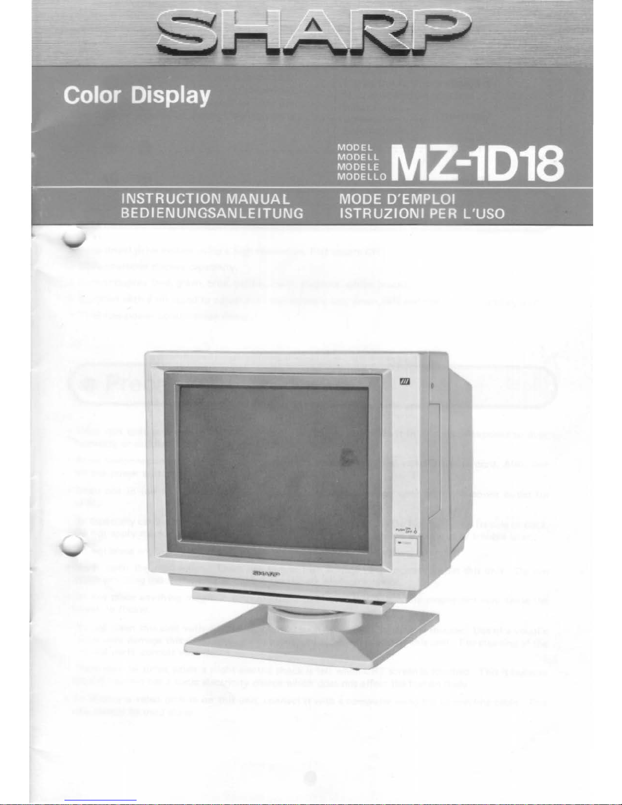
Thank
you
for
buying
Sharp's
CRT
display
(MZ-1 D18).
This
unit
consists
of a color
dis-
play
un•t
(MZ-1 D17)
and
tilt
stand
(MZ-1
S13).
Please
read
this
manual
carefully
for
proper
use.
Also,
be
sure
to
keep
this
manual for
later
use.
Th s
manual
should
be
helpful
during
use
or
when
problems
arise.
Input
signals
..
Connection
..
Specifications
.
.
................
4
5
.
.....
-
........
5
(•
Features
)·
GB
direct drive
system
using a high
resolution,
Flat
square
CRT.
•
2000
character
display
capability.
• 8 col
or
display
(red,
green,
blue,
yellow,
cyan,
magenta,
whtte,
black).
•
Supplied
with a tilt
stand
to
adjust
the
viewtng
angle
(up,
down,
left
and
right)
of
the
display
unit.
•
71 W low
power
consumption
destgn
(•
Precautions
)
•
Since
this
unit
contains
precision
parts
such
as ICs,
do
not
place
it
in a
location exposed
to
dust
,
humidity
or
sudden
changes
in
temperature
.
•
When
disconnecting
the
power
plug,
always
pull
the
plug itself
and
not
the
power
cord
. Also,
turn
off
the
power
switch
before
pulling
the
plug.
•
When
not
in use
for
long
periods
of
time,
disconnect
the
power
cord
from
the
power
outlet
for
safety
.
•
Be
especially careful
when
handling
the
CRT
. Do
not
hit
or
drop
it
Do
not
turn
it
on
its side
or
back
.
Do
not
apply
mechanical
shock
or
vibration.
Such
abuse
may
become
the
source
of
trouble
later
.
not
place
anything
on
this
unit,
as doing
so
may
deform
the
cabinet
.
• Never
open
the
rear
cover. There
are
several high voltage
parts
located
within
this
unit. Do
not
touch
anything
inside
this
unit
as
there
is
the
danger
of
electric
shock
.
• Do
not
place
anything
magnetic
such
electric
clocks
near
this
unit. The
magnetism
may
cause
the
screen
to
flicker.
• Do
not
clean
this
unit
with
any
volatile
liquid
such
as
alcohol,
benzine
or
thinner.
Use
of
a volatile
li
quid
may
damage
this
unit
. Always use a
soft, dry
cloth
when
wiping
this unit. For
cleaning
of
the
internal parts, consult
your
dealer
.
•
There
may
be
times
when
a slight
electric
shock
is felt
when
CRT
screen
is
touched.
This
is
because
the
CRT
screen has a
static
electricity
charge
which
does
not
affect
the
human
body.
•
To
display a
video
picture
on
this
unit,
connect
it
with a computer
using
the
con
necting
cable
. This
unit
cannot
be
used
alone
.
Page 4
( • Names
and
functions
of
ea
ch
part
)
M;t.!.!Qi£1
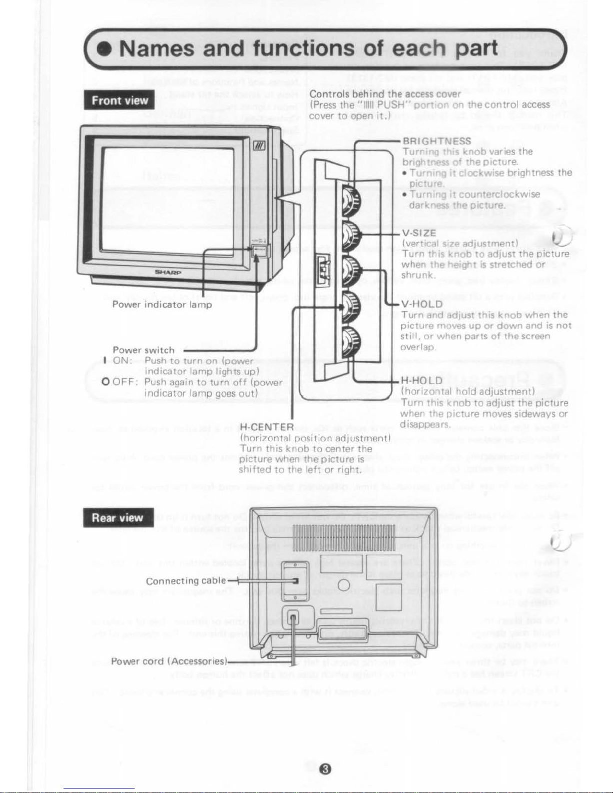
Controls
beh i
nd
the
access
cover
(Press
the " Ill
PUSH"
port
nn
on
the
control
access
cover
to
open .
t.,
!7lll
"
ID
r-1
~~
J
~
=!#
~
m
~
I=
~
......._
,I
ll~
Power indi
cator
lamp
p
Power
switch
~
I ON Push
to
turn
on
(power
indicator
lamp
lights
up)
O
OFF:
Push again
to
turn
off
(power
p
indicator
lamp
goes
out)
H-
CENTER
(horizontal
position
adjustment)
Turn
this
knob
to
center
the
picture
when
the
picture
is
shifted
to
the
left
or
right.
BR
GHH
ESS
T ng t o varies
the
br•"
08Sl,
I
t;
~::tu
re.
• T
mng
rt c ockwrse brightness
the
P•
tu•e
•
Tu
nrng
11
counterclockwise
d kness
the
prcture.
V
-SIZE
t
(vert Jl srze
adjustment
I
~
Turn
:1 rs
knob
to
adjust
the
picture
when
the
t>erght is
stretched
or
shrunk
V-
HOLD
Turn
1d
adjust this
knob
when
the
p1cture moves
up
or
down
and is
not
still,
or
when
parts
of
the
screen
overlap.
H·
HOLD
(horizontal
hold
adjustment)
Turn
this
knob
to
adjust
the
picture
when
the
p1cture moves sideways
or
disappears
Page 5
(•
How
to
attach the tilt stand
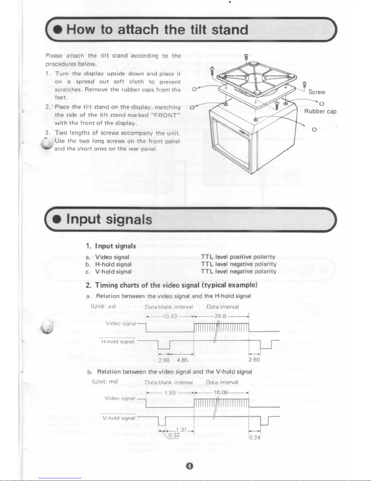
Please
attach
the
tilt
stand
according
to
the
procedures
below.
1.
Turn
the
display upside
down
and
place
it
on
a spread
out
soft
cloth
to
prevent
scratches. Remove
the
rubber
caps
from
the
feet.
2.
·Place
the
tilt
stand
on
the
display, matching o
the
side
of
the
tilt
stand
marked
"FRONT"
with
the
front
of
the
display.
3.
Two
lengths
of
screws
accompany
the
unit.
Use
the
two
long screws on
the
front
panel
and
the
short
ones
on
the
rear panel.
( • Input signals
1.
Input
signals
a.
Video signal
b. H-hold signal
c. V-hold signal
TTL
level positive
polarity
TTL
level negative
polarity
TTL level
negative
polarity
2. Timing charts
of
the
video signal (typical example)
a.
Relation
between
the
video signal
and
the H-hold
signal
(Unit: ,us)
Data blank interval
Data interval
-10.43
--2g_8------.;
H:i:
1
:
0
5
~~:~:
1
l_____
rnnlllllllllllll~
'--
__
--u
: : u
--~---'
~
2.98
4.85
260
b. Relation
between
the
video signal
and
the
V-hold signal
(Unit:
ms)
Data blank interval Data interval
-193
-~16.09-;
V"'""''"''~
Mlllllllllill!
V-hold
sognal
j ' j
w-
~;~~37.....!
i.......J
~
' 'o.24'
0
)
)
Page 6
(•
Connection
)
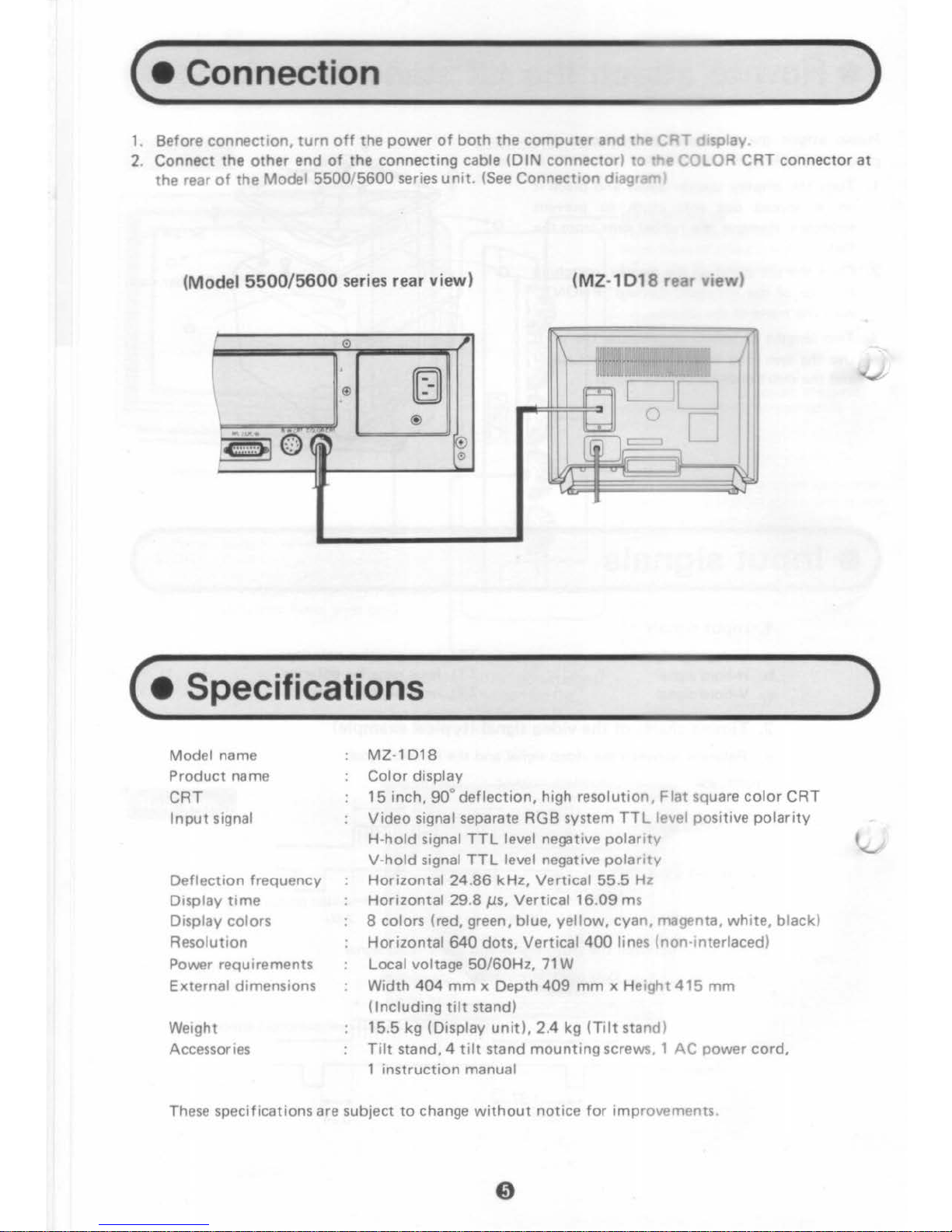
1. Before
connection,
turn
off
the
power
of
both
the
computer
and
the
CAT
d1splay
2.
Connect
the
other
end
of
the connecting cable
(DIN
connector)
to
the
COLOR
CAT
connector
at
the
rear
of
the Model
5500/5600
series
unit.
(See
ConnectiOn
diagraml
(Model
5500/5600
series rear view) (MZ-
1018 rear
view)
--
0
"'
I
rt:rr:\~~~···
m
~uu~:~il'
'
®
[
l[
J
®
0
~l
.0
(~
~
((IJJ(~
)
0
~
~
=
J
( • Specifications
Model name
Product
name
CAT
Input
signal
Deflection
frequency
Display
time
Display colors
Resolution
Power requirements
External
dimensions
Weight
Accessories
MZ-1D
18
Col
or
display
15
inch,
90°
deflection,
high resolution,
Flat
square col
or
CAT
Video
signal separate RG B system
TTL
level positive
polarity
H-hold
signal
TTL
level negative
polarity
V-hold
signal
TTL
level negative
polarity
Horizontal
24.86
kHz,
Vertical 55.5 Hz
Horizontal
29.8
Jls,
Vertical 16.
09
ms
8 colors (red, green, blue,
yellow,
cyan,
magenta,
white,
black)
Horizontal
640
dots,
Vertical
400
lines (non·mterlaced)
Local voltage
50/60Hz,
71
W
Width
404
mm
x Depth
409
mm x Height
415
mm
(Including
tilt
stand)
15.5
kg
(Display
unit),
2.4 kg
(Tilt
stand)
Tilt
stand, 4
tilt
stand
mounting
screws. 1
AC
power
cord,
1
instruction
manual
These specifications are subject
to
change
without
notice
for
improvements.
)
Page 7

Einleitung
Wir
freuen uns,
dal3
Sie sich
zum
Kauf
des Far·
bbildschirm-Anzeigegeriites (MZ-1
018)
von
Sharp entschieden haben. Das Gerat besteht aus
der Bildschirmanzeige
(MZ-1
017)
und
dem
Kippstander
(MZ-1
513).
Fur den richtigen
Gebrauch
lesen Sie diese Bedienungsanleitung
bette sorgfaltig
durch.
Fur spiitere Bezugnahme
die
Bedienungsanleitung sorgfiiltig aufbewahren.
Diese Bedienungshinweise sind
nutzlich
zum
Gebrauch nud beim
Auftreten
von eventuellen
Betriebsstorungen.
lnhalt
Ausstattungsmerkmale .
Vorsichtsma13nahmen .
Bezeichnung
und
Funktionen
der einzelnen Teile
.....
.
Anbringen des Kippstiinders
Eingangssignale
..
Anschlul3we
ise
..
Technische Oaten
(•
AusstaHungsmerkmale
SE
ITE
6
6
7
8
8
9
9
)
- 1GB·Direktantriebssystem
unter
Verwendung
eener
quadratischen
Flachbildrohre
mit
honer
Aut-
sung.
•
2000
Zeichen Anzeigekapazitiit .
• 8-farbige Anzeige
(rot,
gri.in, blau, gelb, cyan, magenta,
wee13,
schwarz).
• Wird
mit
einem Kippstiinder geliefert,
zur
Einstellung
des
Betrachtungswinkels (aufwiirts, abwiirts,
links
und
rechts) des Bildschirms
•
Geringe Leistungsaufnahme (71 Wl.
( • VorsichtsmaBnahmen
)
• Dieses Geriit
enthiilt
hochprazise verarbeitete Bauteile
wir
ICs usw. Daher
das
Geriit
nicht
an
Orten
aufstellen,
wo
es
plotzllchen
Temperaturschwankungen, Staub
oder
hoher
Feuchtigkeit
ausgesetzt
ist.
• Beim Ziehen
des
Netzsteckers stets
am
Stecker,
nicht
am Kabel anfassen. Den Stecker nach
Ausschalten
des
Gerates ziehen
• Wenn
das
Geriit liingere
Zeit
nicht
verwendet werden soli,
zieht
man aus Sicherheitsgriinden den
Stecker.
•
Das
Geriit
nicht
anstol3en
bzw
. fallen lassen. Oesgleichen
das
Geriit
nicht
auf
die Seite oder die
Ruckseite
legen. Die
Einwirkung
mechanischer
St613e
bzw.
Vibrationen
vermeiden. Andernfalls
konnen dadurch spiitere Betriebsstorungen verursacht werden,
Bei
der Handhabung
der
Bildrohre
mit
'"tesonderer
Vorsicht
vorgehen.
'
eine·Gegenstiinde
aut
dem Geriit ablegen. Andernfalls
konnte
das
Gehause
verformt
werden.
•
Aut
keinen Fall die Ruckwand
6ffnen.
lm
Geriit befinden sich mehrere Hochspannung-ruhrende
Teile, die
zu
berlihren iiul3erst gefiihrlich ist.
Auf
keinen Fall Teile
im
lnneren dieses Geriites berl.ihren,
da
die Gefahr eines elektrischen Schlages gegeben ist.
• Keine magnetischen Gegenstiinde, wie z.B. die Magneten von elektrischen Uhren
in
die Niihe dieses
Geriites bringen. Andernfalls kann der Magnetism
us
B ildschirmflackern verursachen.
•
Dieses
Geriit
nicht
mit
chemischen Reinigern ,
Alkohol,
Benzin oder Farbverdiinner reinigen.
Zum
Reinigen stets ein weiches trockenes Tuch verwenden. Durch den Gebrauch von chemise hen Reinigen
wird
die Oberfliiche
des
Geriites angegriffen.
Zum
Reinigen innerer Teile wendet man sich
an
den
Handler.
•
Bei
Beruhren der Bildschirmoberflache spurt man eine leichte elektrische Wirkung.
Dieses
Phiinomen
wird
durch die elektrostatische Ladung
des
Bildschirms ausgelost,
es
stellt keine Gefahr
fiir
den
menschlichen
Korper
dar.
•
Um
eine Bildwiedergabe zu bewirken ist der Anschlul3 dieses Geriites
mit
dem mitgelieferten Ansch·
lul3kabel
an einen
Computer
erforderlich. Dieses Geriit allein kann
nicht
verwendet warden.
Page 8

e Bezeichnung und Funktionen der
eanze
lnen
Teile
1
ii.l:!f"BHD
Einschalt·Anzeige
Netzschalter
-----"
ON
Zum
Einschaoten
dru
ken.
(Die Einschalt-Anzeige
leuchtet auf)
0
OFF
Zum
Ausschalten
die
Taste
nochmals
dri.K:ken. (Die
Einschalt-Anzeige erlischt.)
H-CEN
TER
(X· Lage-Regler)
erabdeckung
___
HEL
L ;KEITSREGLER
(BR
IGnTNESSI
Zur
Veranderung helr;:;l<eit
verwendet
man d ese
Reg e•
•
Durch
Drehen
om
Uhn:e<gers
nn
nimmt
die
Helligkeot
zu
•
Durch
Drehen gegen
den
Uhr-
zeigersinn nommt
die
Helligken
ab.
)l
::I-+-1-
V-SIZE
(Tei
lb
i ld-Hohenregler)
Zur
Einstellung
des
Bildes, wen
Bildhiihe
gedE
hnt
oder gestaucht ist.
BI L
DFANG
(V-HO
LD)
Wenn
',
81
d nach oben oder
unten
"d
urcr
-..lft".
oder wenn der
Bildsch rme
m uberlapptes Bild
anzeogt,
nommt man die Einstellung
mi;
dsesem Regler
vor.
'----+-
ZEI
LENEINSTEL
LUNG (H-
HOLD
)
Zeolenfang Eo!lStellung)
Zur
Eonstelll.'IQ des Bildes. wenn das
B
Id
se
twarts
weglauft.
bzw.
verschWJndet
Wenn das Bild nach
links
oder
rechts
verschoben
ist,
dreht
man diesen
Knopf
zum
Einmitten
des Bildes.
Page 9

( • Anbringen des Kippstanders
Zur
Befestigung des Kippstiinders
verfiihrt
man
Wle
nachstehend beschrieben.
1.
Urn
Kratzer
zu vermeiden,
breitet
man eine
weiche Decke aus
und
legt
das
Anzeigegeriit
mit
der
Bildschirmseite nach
unten
gerichtet
vorsichtig
darauf. Die
Gummikappen
der
FliBe
entfernen.
2 Den Kippstander am Anzeigegerat be·
0
festigen, dabei
darauf
achten, daB die
mit
"
FRONT"
markierte
Seite
des
Kippstanders
mit
der Frontseite der Bildschirmanzeige
ausgerichtet
wird.
Schrauben (zwei verschiedene Uingen) sind
mit
diesem
Geriit
mitgellefert
. Verwenden
Sie die beidsn langen Schrauben an
der
Front
und
die kurzen
an
der Ruckwand .
( • Eingangssignale
1. E ingangssignale
a.
Videosignal
b. H-
hold
signal (Zeileneinstellsignal)
c. V
·ho
ld
signal (Bildfang·Signal)
TTL-Pegel
, positive Polung
TTL·Pegel, negative Polung
TTL·Pegel
, negative Polung
2. I mpulsiibersicht des Videosignals (typisches Beispiel)
a.
Verhaltnis
zwischen Videosignal
und
Zeileneinsteii·Signal
IE1nheit JlS)
Leerstellen-1 ntervall Oaten·
In
tervall
10.43--29,8----o;
.
v;o~,,~,~
~1111111111111
Zedene1nsteii·S1gnal
~
r j
~
2.98
4.85
' ';;!
b.
Verhaltnis
zwischen Videosignal
und
Bildfang·Signal
IEmhe1t. msl Leerstellen Interval! Oaten-Interval!
:~
1,93-++--
16,09--
_"'"""""
2:-u
rrnrr1111111111111
1
Blldfang·S,gnal ! . !
~
:""<t.+;;-;.1;37
_!
[.__.;
·
~
' 'o.24.
)
)
Page 10

( • AnschluBweise
)
1.
Vor
dem AnschluB sowohl den
Computer
als auch
das
Bildschirm-Anzetgegera ausschalten.
2.
Das
andere
Ende
des
AnschluBkabels
(DIN-Steckerl
verbindet man
mn
dl'
.....
SchwarzeiBrohren-
AnschluBstecker
(Color
CRT)
an der Ruckseite eines Gerates der
Modell
e
5500/5600
(siehe
Zeichnung).
(Modell
5500/5600
, Riickseite)
(MZ-1018
, Ruckseite)
0
0
(•
Technische Oaten
)
Model! name
Produ ktnama
Bildrohre
Eingangssignal
Ablenkfrequenz
Anzeigezeit
Anzeigefarben
Auflosung
St romversorgung
AuBere Abmessungen
Gewicht
Zubehor
MZ-1018
Farbbi
ldsch i rm-Anzeigegerat
Quadratische hochauflosende
15-Zoii-Fiach
farbbildrohre,
so•
Ablenkung
Videosignal, separates RGB-System, TTL-Pegel, positive polung
Zeileneinsteii-Signal, TTL-Pegel, negative Polung
Bildfang·Signal, TTL-Pegel, negative
polung
Horizontal
24,86
kHz,
vertikal
55,5
Hz
Horizontal
29,8
ps,
verti
kal
16,09
ms
8 Farben
(rot,
grun, blau, gelb,
cyan,
magenta, weiB, schwarz)
Horizontal
640
Bildpunkte,
vertikal
400
Zeilen (oh ne Zeilensprung)
Regionale Netzspannung
50/60Hz,
71
W
404(8) x 409(T) x 415(H)
mm
(EinschlieBiich
Kippstanderl
15.5
kg (Bildsch irm-Anzeigegeratl. 2.4 kg (
Kippstanderl
Kippstander, 4 Befestigungsschrauben
fur
den Kippstander,
1 Netzkabel, 1 Bedienungasanleitung
Anderungen der Technischen Oaten vorbehalten.
Page 11

Introduction
v..s vous
felicitons
pour
I'
achat de
cet
af-
fochage
couleur
(MZ-1D18)
Sharp. Cet appareil
se
compose
d'un
affichage
couleur
(MZ-1
D17)
et
d"un
support
inclinable
(MZ
-1 S13). A
fin
d'utiliser
correctement
cet
affichage
couleur,
veu lez
lire
ce
mode
d'emploi
tres
attentive-
men!.
Ce
mode d'e
mploi
sera
d'une
aide pre-
c•euse
pendant
!'utilisation
ou
en
cas
de
prob-
leme.
( • Caracteristiques
Table des matieres
Caracteristiques
....
Precautions . . . . . .
Designation
et
fonction
de phaque
partie
. .
..
Montage
du
support
inclinable
Signaux
d'entree
Raccordement .
Fiche technique
PAGE
10
10
11
.
12
12
13
13
).
'ysteme a commande
directe des signaux
RGB
equipe
d'un
tube
cathodique a definition
elevee
et
ondes rectangulaires
sans
contraste.
• Capacite
d'affichage
de
2000
caracteres.
•
Affichage
de 8
couleurs
(rouge, vert, bleu, jaune, turquoise, magenta, blanc,
noirl.
•
Fourni
avec
le
support
inclinable
pour
permettre
le reglage de I' angle
d'
observation
(haut,
bas,
droite
et
gauche) de I'
unite d'a
fficha
ge.
•
Conception a faible
consommation
d'energie
(71 W).
( • Precautions
)
• Cet appareil
comportant
des composants de precision, tels que des
circuits
integres (IC), il ne
doit
pas etre place dans
un
endroit su1
et
a des variations brusques de temperature,
ni
dans
un
end
roit
humide
ou poussiereux .
•
Pour
debrancher le
cordon d'alime
ntation, toujours
tenir
la
fiche
et
non
pas
le
cordon
proprement
dit. De
plus, la
fiche
ne
doit
etre
debranchee qu'apres
avoir
coupe
l'alimentation
.
•
Lorsque l'appareil n'est pas
utilise
pendant
une periode prolongee, debrancher
le
cordon
d'a
limenta-
tion
de la prise secteur
par
mesure de securiu!.
•
Ne
pas
heurter
cet
appareil
et
ne pas
le
laisser
tomber. De
plus, il ne
dolt
pas etre couche sur le cOte
ni a l'arriere. 11
ne
doit
pas etre soumis a des chocs mecaniques
ni
il des
vibrations.
Cela
pourrait a la
ongue
etre
une source de problemes.
D'une
maniere generale, l'ecran
cathodique
doit
~tre
manipu
le
avec
soin.
• Ne rien placer
sur
cet
appareil, cela
pourrait
detormer
son
boitier
.
• Ne jamais
ouvrir
le
capot
arriere. Cet appareil
comporte
plusieurs pieces
haute
tension pou
vant
etre
dangereuses. Ne rien
toucher a l'mterieur
de
cet
appareil car
il
y a
un
danger
d'electrocution.
• Ne pas placer d'
objets
magnetlques, tels
qu'aimants
ou horloges
electrique
s,
il
proximite
de
cet
ap-
pareil.
Le magnetisme
affecterait
son
fonctionnement
et
provoquerait
un
scintille
ment
de
l'ecran.
•
Ne pas
nettoyer
cet
appareil avec
un
produit
volatile,
tel que de
l'alcool
, de la benzine ou
du dil
uant.
Toujours
utiliser
un
chiffon
doux
et
sec
pour
essuyer
ses
surfaces.
L'emploi
d'un
liquide
vol
ati
le
peut
endommager l'appareil.
Pour
le
nenoyage
de l'interieur,
se
renseigner aup
res
du
depositaire.
•
On
peut
parfois
ressentir un leger
effet
electrique
lorsque
l'on
touche
la surface de l'ecran
cathodique
.
Cela
provient
de
la charge d'
electriciu!
statique
de
l'ecran
et
n'a aucun effec t sur le corps
humain.
•
Pour
obtenir
une image
video
avec
cet
appareil, le raccorder a
un
ordinateur
au
moyen
du cable de
raccordement
fourni
. Cet appareil
ne
peut
pas
etre utilise
tout seul.
Page 12

e Designation et fonction de chaque partie
'ii!J@i,ji
lnd
icateur d
'ali
ment
ation
lnterrupt
eur
d'al i
mentat
ion
ON
Appuyer
pour
enclencher
(L'indicateur
d'alimentation
s'allume.)
0
OFF
Appuyer
une nouvelle fois
pour
dec lencher
(L'indicateur
d'alimentation
s'eteint.)
Comm
andes situ
ees
derriere le couvercle d'acces
(Presser la
portion
marquee "IlD PUSH" sur le couvercle
d'acces
pour
l'ouvrir)
___
L
UMINOSITE
(BRIGHTNESS)
,----
+-
--
La
lumt\'10511
0 . mage
peut
etre
modi~t~e
en
tournant
ce
bouton.
• L'image s'eclaircit lorsque le
bouton
est
tournl!
dans
le
sens
des aiguilles
d'une
montre.
• L'tmage s assombrit lorsque
le
bouton
est
tourne
dans
le
sens
eo
atre
des
aigui d"une
montre.
U
a-~-
HA
UTEUR
VER
TIC
ALE
(regia.
de
la
hauteur
verticale)
Agir
~f
ce
bouton
pour
regler
I'
image lorsque
la
hauteur
est
allonaee
ou
retrl!cte.
STA
B,
.ITE
VERTIC
ALE
(V-HOLD)
Aju~
ce
bouton
en
•e
tournant
lorSQue
I mage
se
deplace vers le
haut
ou
vers le bas et
n'est
pas
immobile,
ou
lorsque
des
parties de !'image
se
recou• rent
---+-
SYNC·
IRONISATION
HOR
IZONTALE
(H·H
OLD
)
(regl
de
la synchro•• isation
horizv
tale!
CENTRAGE
HORIZONTAL
(reglage
du
centrage
horizontal)
Agir
sur
ce
bouton
pour
centrer
Agir
sur ce
bouton
pour
regler
I' image
lorsqu'elle
se
deplace
lateralement
ou
disparait.
I' image lorsqu'elle est decentree sur la
gauche
ou
sur
la
droite.
Page 13

( • Montage
du
spport inclinable
Le
support
inclinable
peut
etre
monte
en sui-
.rant
la
procedure
su
ivante.
Renverser J'affichage
et
le placer
sur
un
tissu
doux
etendu
pour
eviter
les
rayures.
Retirer
les capuchons
en
caoutchouc
des
pieds.
2. Placer le
support
inclinable en faisant corres-
pondre
le
cote
du
support
inclinabel
marque
"FRON
T" (avant)avec
l'avant
de
l'affichage.
3
Des
vis de deux longueurs accompagnent
J'appareil.
Utiliser
les
deux
vis longues
sur
le
panneau avant
et
les courtes sur le panneau
arriere.
(•
Signaux d'entree
1. Signa
ux d'entree
a.
Signal
video
b. Signal de stabilite-H
c.
Signal de
stabilite-V
Niveau TTL,
polarite
positive
Niveau
TTL,
polarite
negative
Niveau
TTL,
polar
ite
negative
2. Diagramme des temps du
sig
nal video (exemple type)
a.
Relation
entre
le
signal
video
et
le signal
de
stabil
ite
horizontale
(H)
(Unite·
psi
Interval le
v•
·rge
de
donnees lntervalle
de
donnees
10.43--29.8------!
Signal
.
video~
rrnm1111111111111~
Sognaldestabllote
-
H~
~{
!
LJ
--
------~
:
~
·2.6o'
2.98
4.85
b.
Relation
entre
le signal
video
et
le
signal de
stabilite
verticale
(V)
(Unite:
ms)
lntervalle
voerge
de
donnees
lntervalle de donnees
-
1,93~'~16.09-
'
SOoo•''''"'~
~1111111111111
S•gnal
de stabolite-V : :
1.
r-
: I L-J
~-~
~;37
_J
L...:
~
' 'o.24
1
)
)
Page 14

( • Raccordement
)
1.
Avant
de proceder
au
raccorde
ment, couper
l'alimentation
de
l'ordinateur
et de I ecran
catho
dique.
2. Branc her
!'autre
extremite
du
cable de
connexion
(connecteur
DIN)
sur le connecteur de l'affichage
Couleur a l'arriere du modele serie
5500/5600
(Voir
schema).
(Modele
5500/5600
, face arriere)
(MZ
·1
018
face arriere)
0
®
0
( • Fiche technique
)
Designation
du
modele
Appellation
du
produit
Lampe a reyons cathodiques
Signal
d'entree
F niquence de deviation
Duree d'affichage
Couleurs
affichees
Resolution
Alimentation
Dimensions extcrieures
Poids
Accessoi
res
MZ-1018
Affichage
couleur
Tube
cathodique a fond
plat
carre
dt~
15",
90°
de
deviation,
et
definition
elevee
System
RGB
separe du signal video, niveau
TTL,
polarite
positive
Signal de
stabilite·H:
Signal
TTL,
pola
r te negative
Signal de
stabilite·V:
Signal
TTL, polar
te negative
Horizontale: 24,86
kHz
Verticale:
55,5
Hz
Horizontale: 29,8
JJ.s
Verticale:
16,09
ms
8 couleurs, (rouge,
vert,
bleu, jaune, turquoise, magenta, blanc,
noirl
Horizontale: 640
points
Verticale:
400
I ignes (sans entrelacemen
tl
Tension locale
50/60Hz,
71W
404(L) x 409(P) x 415(H) mm
(Support
inclma
ble compris)
15,5 kg (rayons cathodiques), 2,4 kg
(support
inclinable)
Support
inclinable, 4 vis de montage
pour
support
inclinable,
1
cordon
d'alimentation,
1 Mode
d'emplo•
Les
specifications sent sujettes a
modification
sans
preavis
pour
amelioration
du
produit.
Page 15

I ntroduzione
Congratulazioni
per
l'ottimo
acquisto
delle
schermo a
colori
MZ-1 D 18, dell a Sharp. Ouesto
prodotto
consiste
delle
schermo a
colori
MZ-
1017
e del
supporto
inclinabile
MZ-1513.
AI
fine
di
usarlo
correttamente,
si
raccomanda
di
leggere
attentamente
questo
manuale. Esse vi
sara
inoltre
di
aiuto
nella soluzione
di
eventuali
difficolta.
( • Caratteristiche
lndice
Caratteristiche
Precau
zion
i . . . . . . . . . . .
..
Designazione e
funzione
delle
parti
Fissaggio del
supporto
pieghevole
Segnali
di
ingresso
Collegamento
Dati
tecnici
....
.1stema
RGB
ad
accoppiamento
diretto
con
tube
CRT
flat
square ad
alta
risoluzione.
• Capacita
di
visualizzazione
di
2000
caratteri.
•
Schermo
ad 8
colori
(rosso, verde,
blu,
giallo,
ciano, magenta,
bianco
e nero).
PAGINA
14
14
15
16
16
17
17
)
•
Fornito
insieme
con
un
supporto
pieghevole
per
regolare
l'angolo
di
visione
delle
schermo nelle
quattro
direzioni.
•
Consume
energetico I
imitate
(71 W).
(•
Precauzioni
)
• Ouesto apparecchio
contiene
parti
di
elevata precisione (come
per
esempio
circuiti
integrati),
per
cui
non
deve
essere
installato
in
luoghi
soggetti a
importa
nti
cambiamenti
di
temperatura, polverosi o
mol
to
umidi.
• Per scollegare il cave
di
alimentazione,
afferrarne
sempre bene la spina; non
tirare
il cavo stesso.
I
noltre,
prima
di
scollegarlo da rete, spegnerlo.
•
Quando
non
si
intende
usare
il
video
per
lunghi
periodi
di
tempo
si
raccomanda
di
scollegare il cave
di
corrente.
•
Non
sottomettere
il
video a colpi.
Non
voltarlo
ne
sui
late,
ne
all'insu.
Non
sottometterlo a scosse
o
·ibrazioni,
per
evitare possibili danni.
Trattare
il
video
CRT
con
cura.
on
disporre
nessun oggetto sopra
il
video.
Cio
potrebbe
causare
deforma
zioni
dell'involucro.
•
Non
togliere mai il
coperchio
posteriore. Parecchie
parti
interne
sono
sotto
alta tensione, e il
contat-
to
con
esse
potrebbe
essere
causa
di
scosse
elettriche.
•
Non
avvicinare magneti (come
per
esempio
il
magnete
di
un
orologio
elettrico)
al
video. Cio
potrebbe
causare
un
tremolio
nello
schermo.
•
Non
pulire
il
video
usando
liquidi
volatili
quali
alcool, benzina o
diluent
i. Usare sempre
uno
strofi-
naccio
mordibo e asciutto.
L'uso
di
liquidi
volatili
potrebbe
danneggiare la
rifini
tura. Per
quanta
riguarda la
pulizia
delle
parti
interne,
rivolgersi al
proprio
rivenditore.
• A
volte,
e possibile che
toccando
lo
schermo
si
abbia la sensazione
di
sentire l'
elettricita.
Ouesto e
dovuto
effettivamente
all'elettricita
statica caricatasi
sullo
schermo,la
quale
none
comunque
dannosa
all'organismo
umano.
• Per
riprodurre
delle
immagini
su
questo video,
collegarlo
ad un
computer
facendo
use
dell'apposito
cavo
fornito.
11
video
non
puo
essere
usato
come
unita a se
stante.
Page 16

• Designazione e funzione delle parti
lnd
icatore di
funzionamento
I
nterruttore
di
corrente
----
ON (acceso): Premere per accendere
(l'
indicato
re
di
funzionamen
to
si
accende).
0
OFF(spento): Premere
di
nuovo
per
spegnere i
I video-
(l'indicatore
di
funziona-
mento
si
speqne).
H-CENTER
Comandi s
otto
il coperch1o
(Per aprire
il
coperchio. premere quest'
ultimo
lata
con
l'indicazione
11111
PUSH
---
LUM
II'IOSITA (BRIGHTNESS)
..----
-1-
---..
G1ran
o q
1est1
nopola
si
regola
la
u os
ta
de
..
,,magine.
• G1rare n senso
orano
per
rendere
l'immag
ne
plij
luminosa.
•
Gm:re
nso
antiorano
per
rendere I magme
piu
oscura.
U
OII--~~V
-SIZE
(regol
1one
vert1Cale
delle
form
Far gir.,re questa manopola per
regolar·! l'1rnmagme
quando
le
forme
appa•<>'IO
allul"gate o accorciate.
COMA
NDO
01
ALLINEAMENTO
VERT
ICALE
IV-
HOLD
)
Toccaro
questo
cor
ar
do
quando
l'immagii"C sfugge verso I'
alto
oil
basso. o
q.;~ando
le
immagini
si
sovr
appongono
---+-
COMANDO 01
ALLINEAMENTO
ORIZZONTALE
(H-
HOLD
)
(regola/IOr e del tracc.orr •
.:nto
orizzontale)
Far girare questa
manopola
per
regolare fermare
I' immagine
quando
(regolazione del
centra
immagine)
Far
girare questa manopola pe r
riportare
l'immagine
al
centra.
quando
e spostata
ve
rso destra o
si
sposta sui
lati
o sparisce.
sinistra.
Ca
vo
di ali
mentazione
(
Page 17

(•
Fissaggio del supporto pieghevole
Attaccare
il
supporto
pieghevole nel
modo
descritto
di
sequito.
1.
Voltare
lo
schermo
all'
ingiu,
disponendolo
su
una
stoffa
morbida,
per
eviatre
che
si
graffi.
Togliere
i cappucc1
di
gomma dai
piedini.
2.
Disporre
il
supporto
pieghevole
sullo
schermo
facendo
corrispondere
il
lato
del
supporto
con
la
scritta
FRONT
(davanti)
con
il
davanti
dello
schermo.
3. lnsieme
all'apparecchio
sono
fornite
viti
di
due
lunghezze. Usare le due vit1
piu
lunghe
sui
pannello
frontale
e guelle
piu
corte
sui
pannello
posteriore
dell'apparecchio
( • Segnali
di
ingresso
1. Segnali di ingresso
a.
Segnale
video
b. Segnale H-
hold
c.
Segnale
V-hold
Polarita
positiva
livello
TTL
Polarita negativa
livello
TTL
Polarita negativa
livello
TTL
2. Tabelle di sincronizzazione del segnale video (esempio tipico)
a.
Relazione
tra
il segnale
video
e il segnale
H-hold
lntervallo
senza
dat1
lntervallo con dati
10.43
-~
·-
-
29.8----.:
Se::~:':v~:~:~
~IIIIIIIIIIII:L_
__
--u
! u
H
2,98 4.85 2,60
b. Relazione tra
il
segnale
video e il
segnale
V-hold
IUnita msl
lntervallo
senza
dat1
lntervallo
con
dati
·-
1,93-
16.09-
"'""
""·:~
~1111111111111
Segnale
V hold l 1 l
~
:"'t
.
~
}_.37--..:
:..........:
'~
· 'o.24:
)
)
Page 18

( • Collegameoto
)
1. Prima
di
eseguire il collegamento, spegnere sia il
computer
che il
video
.
2. Collegare
l'altro
capo del cava
con
presa
Dl
N alia presa
CRT a colore sui retro
dell'apparecchio
model
la
5500/5600.
(Vedere schema collegamenti)
(Retro
del
Modello
5500/5600
)
(Ret
ro
deii'MZ-
1018)
0
®
~·~·
0
-
:;·.
,
~
(•
Dati tecnici
Modello
Designazione del
prodotto
Tuba
CRT
Segnale
di
ingresso
Frequenza
di
deflessione
Tempo
di
visualizzazione
Colori
dello
schermo
Risoluzione
Alimentazione
Dimensi
oni
esterne
Peso
Accessori
_,
_)
m
rE
···
=~
······
~
CJ'
®
~
0
MZ-1018
Schermo a
colori
r1
~
~
[
~
...
~
I
~
)
Tuba
CRT
flat
square
di
15
poll
ici,
90°
defl
essione, ad alta
risoluzione, a
colori
Segnale video, a sistema
RGB
sep
arato, livello
TTL,
polar
itil
positiva
Segnale H-hold,
polarita
negativa l
ivello
TTL
Segnale
V-hole,
polar
ita
negativa I
ivello TTL
Orizzontale
24,86
kHz, verticale 55,5 Hz
29,8
/J.S
orizzontalmente e 16,09
ms vertical
mete
8 (rosso, verde,
blu,
giallo, ciano, magenta, bianco
e nero)
rozzontale
640
punti,
verticale
400
nghte {non
intrecciate)
Tensione locale 50/
60Hz,
71
W
larghezza
404
mm x profondita
409
mm
x altezza
415
mm
(Supporto
inclinabile
incluso)
15,5 kg (video
CRT).
2.4
kg
(supp
orto pie
ghevole)
Supporto
pieghevole, 4
viti
per il su
pporto,
1 cava
di
alimentazione, manuale delle istru
zio
ni
Dati
tecnici soggetti a
modifiche
senza
preavviso, per eventual i m igl
ior
amen
ti.
Page 19

This
apparatus
complies
with
requirements
of
BS
800
and
EEC directive
82/499/EEC
.
Dieses
Gerat
stimmt
mit
den
Bedingungen
der
EG-Richtlin i
en
82/499/
EWG
i.iberein.
Cet
appareil
nipond
aux
specifications de
la
directive CCE 82/
499/CCE.
Dit
apparaat
voldoet
aan de vereiste EEG -
reglementen 82/
499
/EEG.
Apparatet
opfylder
kravene i E F
direktivet
82/499/E
F.
Ouesto
apparecchio e stato
prodotto
in
conformita
alle direttive CEE
82/499/CEE
.
Page 20

SHARP CORPORATION
OSAKA, JAPAN
Printed
in Japan
Gedruckt
in
Japan
lmprime
au Japan
Stampato
in
Giappone
TINSZ7466TAZZ
4G
 Loading...