

Page 1
-
SHARP
SERVICE MANUAL
CODE: OO
ZMZID04/1IE
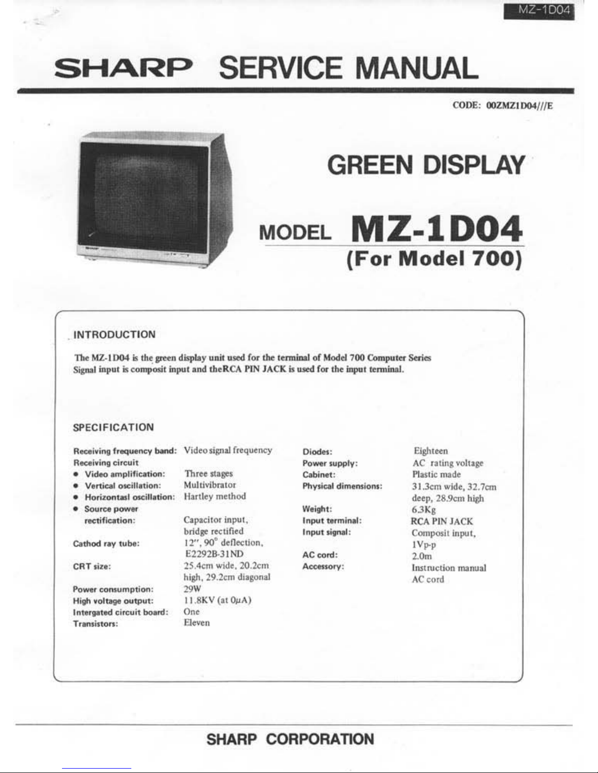
GREEN
DISPLAY
MODEL
MZ-l
D04
(For
Model
700)
TheMZ.llJ04;,tbe_ditplayu.~.oedf"'t""1"",""ol_700Compu
...
Seris
SipoIioo""';,<ompooitlnpu,andIl><RCAPl
NMCJ(;,_
f
.. 'helnpo'lmninaI
.
R_
i"lft
__
, V
id<o"",oI'
,oq""ncy
R_
"'.lmol.
:
~:::.,"":~=
:
:::,
~.;::':~
_ Horiz<wIuoI
__
:
Il.
rll
eymetkod
_
So.o
__
--;".,
_..,....m9~
_:
H~""
_
....
IpU'
·
In
.....
'
odcif<~i._
C.~i""In"",.
bridJOrt<,m' d
~
~~~;
:
~tlon.
25.4<m
....
iJc.20.km
~~.29.2cmdi.oson
..
~lKnV("OjIA)
SHARP CORPORATION
Eiih'een
~~,~';.:.:I'qt
ll.l<mwld<,31.7cm
""
ep,28.'km/U91
:~~INJ
ACK
Com_itin"".,
;~P
'
..
'rue';"., ..........
A(cord
Page 2
Z-1004
FOR SAFER SERVICING
AND
SAFETY
CHECK-OUT
Please pay special attention to the following conditions during servicing and check-out.
1.
Observe cautions
Where
special attention
is
required on such
as
cabinet,
chassis, and component parts
is
noted with caution using
label or stamp.
You
have
to observe there cautions
as
well
as
those
in
Instruction Manual.
2.
Use
parts
of
rated performance
Since parts component used
in
the unit has specific rating
for safety performance such
as
non-inflamability, voltage
withstanding, etc.,
use
the item
of
identical characteristics.
Among
all,
parts components indicated with the "
&.
" mark
in the circuit diagram and parts list must
be
equal
in
its
property
as
it
is
critical to the performance
of
the unit.
3. Replace
the
parts and wiring
on
their original locations
For safety's sake, some
of
items are protected with
in-
sulating materials such
as
tube and tape, or the printed
board
is
isolated from other components. Also, internal
wirings
are
installed and held by such
as
clamp
to
keep
them away from heat generating component and high
tension parts. Whereas, these wirings
have
to be installed
back to their original locations.
2
4. Handle
the
CRT with care
The explosion-proof cathod ray tube
is
guaranteed
of
its
safety against explosion
as
long as it
is
installed in the
unit. However, pay special attention when it
was
removed
from the unit or when servicing it from the back
of
the
unit.
Never
give
impact
of
the cone section.
5. X-ray
The CRT and high tension circuits
have
safety measures
against X-ray. Therefore,
use
the specified parts
to
trouble-
shoot the CRT and high tension circuit, and, never try
to
modify the circuit under any circumstance.
Use
of
the parts
other than specified may cause to
rise
the high voltage
which generates
X-ray
from the CRT.
6. Perform check-out after servicing
After servicing,
be
sure to confirm safety by checking
that
all
removed screws, component parts, and wirings
were replaced
as
before and
see
that no damage has been
done to the serviced area. Besides, ensure insulation
of
the
input signal terminal against metal portion and plug edges.
Page 3
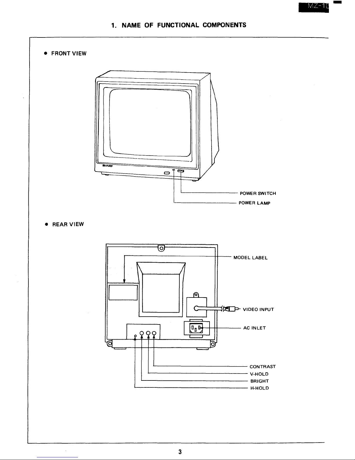
• FRONT VIEW
•
REAR VIEW
1. NAME OF FUNCTIONAL COMPONENTS
./
r
'-
........
c::::I
0
~
CJ
I
000/
l(§I
~
/'
\
-
V
e~
~
;1
f6\
I
(
I
.....----.
1~1
'---'
r§)
'---'
3
POWER SWITCH
POWER
LAMP
MODE
LLABEL
~VI
DEOINPUT
A C
INLET
CONTRAST
V-HOLD
BRIGHT
H-HOLD
--
Page 4
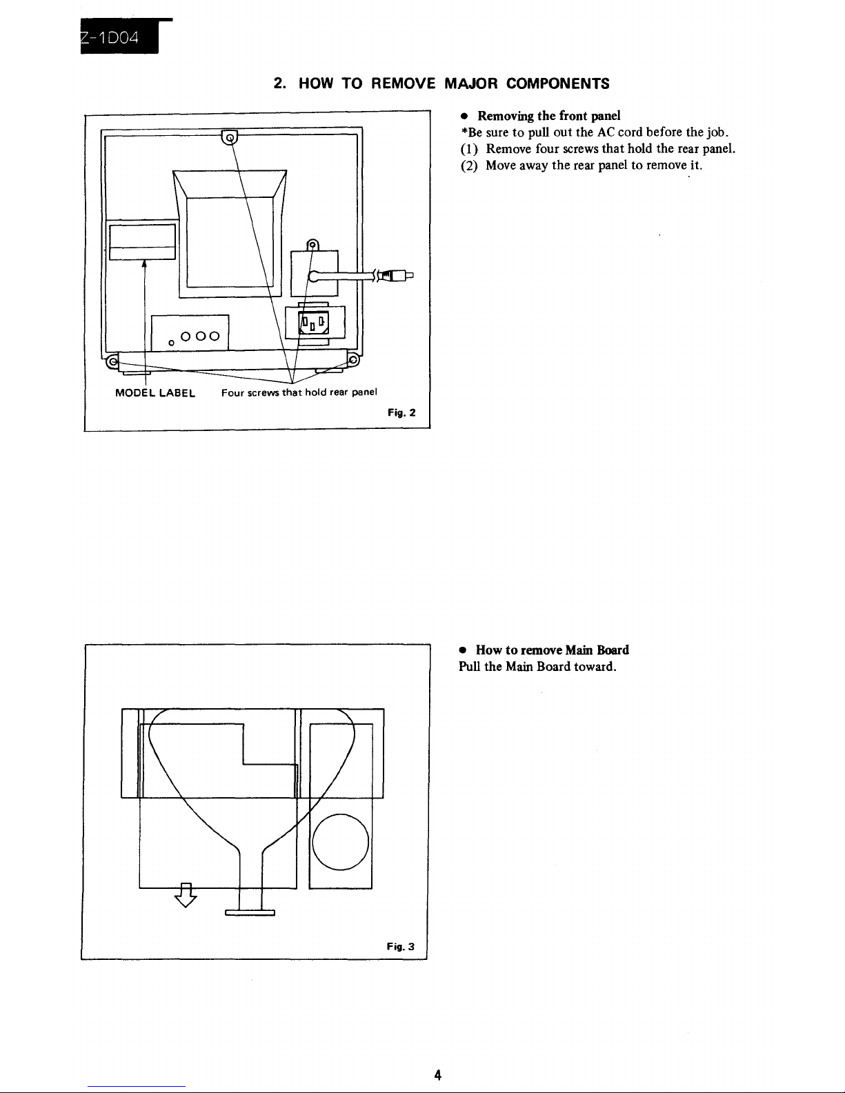
MOOEL LABEL
2.
HOW
TO REMOVE MAJOR COMPONENTS
Four
screws
that
hold
rear panel
Fig. 2
Fig. 3
4
• Removing
the
front panel
*Be
sure to pull out the
AC
cord before the job.
(l)
Remove four screws
that
hold the rear panel.
(2)
Move
away the rear panel to remove it.
• How
to
remove
Main
Board
Pull the
Main
Board toward.
Page 5
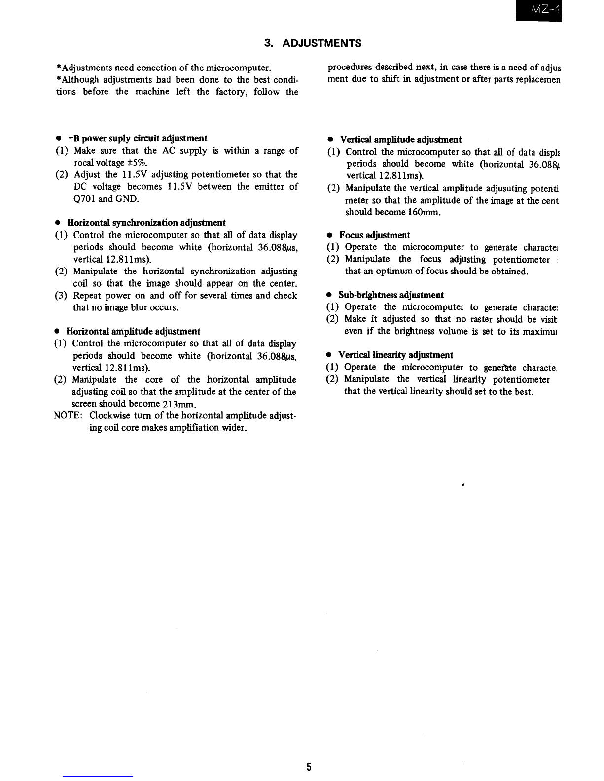
3. ADJUSTMENTS
* Adjustments need conection
of
the
microcomputer.
* Although adjustments had been done to the best condi-
tions before the machine left the factory, follow the
•
+8
power suply circuit adjustment
(1)
Make
sure that the
AC
supply is within a range
of
rocal voltage
±5%.
(2) Adjust the 11.5V adjusting potentiometer so that the
DC
voltage becomes 11.5V between the emitter
of
Q701 and GND.
• Horizontal synchronization adjustment
(I)
Control the microcomputer so that
all
of
data display
periods should become white (horizontal
36.088tLs,
vertical 12.81Ims).
(2) Manipulate the horizontal synchronization adjusting
coil so that the image should appear on the center.
(3) Repeat power on and
off
for several times and check
that no image blur occurs.
• Horizontal amplitude adjustment
(1) Control the microcomputer so that
all
of
data display
periods should become white (horizontal
36.088tLs,
vertical12.811ms).
(2) Manipulate the core
of
the horizontal amplitude
adjusting coil so that the amplitude
at
the center
of
the
screen should become 213mm.
NOTE: Clockwise
turn
of
the horizontal amplitude adjust-
ing coil core makes amplifiation wider.
5
procedures described next, in case there
is
a need
of
adjus
ment due
to
shift in adjustment or after parts replacemen
• Vertical amplitude adjustment
(1) Control the microcomputer so that
all
of
data disph
periods should become white (horizontal
36.08&,.
vertical 12.81lms).
(2) Manipulate the vertical amplitude adjusuting potenti
meter so that the amplitude
of
the image
at
the cent
should become
160mm.
•
Focus adjustment
(1) Operate the microcomputer
to
generate charactel
(2) Manipulate the focus adjusting potentiometer
that an optimum
of
focus should be obtained.
• Sub-brightness adjustment
(1) Operate the microcomputer to generate characte]
(2)
Make
it
adjusted so that no raster should be visit
even
if
the brightness volume is set to its
maximUl
• Vertical linearity adjustment
(1)
Operate the microcomputer
to
gener1rte
characte
(2) Manipulate the vertical linearity potentiometer
that the vertical linearity should set
to
the best.
Page 6
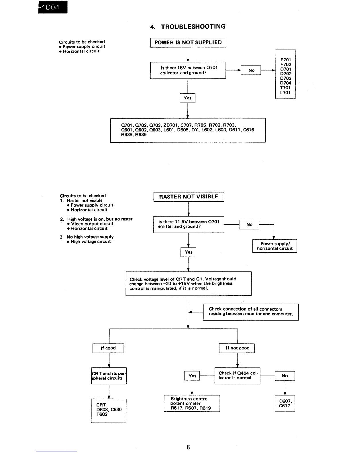
Circuits
to
be
checked
• PQwer supply circuit
• Horizontal circuit
Circuits
to
be checked
1. Raster
not
visible
• Power supply circuit
• Horizontal circuit
4.
TROUBLESHOOTING
POWER
IS
NOT
SUPPLIED
Is
there
16V
between
0701
collector
and
ground?
0701,0702,0703,
Z0701,
C707,
R705, R702, R703,
0601,0602,0603,L601,0605,OY,L602,L603,0611,C616
R638,
R639
RASTER
NOT
VISIBLE
2. High voltage
is
on,
but
no raster
Is
there
11.5V
between
0701
emitter
and
ground?
• Video
output
circuit
• Horizontal circuit
3.
No high voltage supply
• High voltage circuit
Check voltage level of
CRT
and
Gl.
Voltage
should
change between
-20
to
+15V
when
the
brightness
control
is
manipulated, if
it
is
normal.
F701
F702
0701
0702
0703
0704
T701
L701
Check
connection
of
all connectors
residing
between
monitor
and
computer.
CRT
D608,C630
T602
Brightness
control
potentiometer
R617,
R607,
R619
6
0607,
C617
Page 7

Circuit
to
be
checked
Video
and
its peripheral
circuits
Circuit
to
be checked
• Horizontal synchronization
circuit
Circuit
to
be
checked
• Vertical synchronization
circuit
I
PICTURE DOES NOT APPEAR
Observe
the
video signal
at
Q405 base
on
the
oscilloscope.
Is
the
video signal on7
Observe
the
video signal
at
0404
base
on
the
oscilloscope.
Is
the video signal on?
SYNCHRONIZATION NOT POSSIBLE
Horizontal synchronization
is
not
possible
1
0602,0603,
eG06, A623
and
their
per·
ipheral circuit.
I
MZ-1 D04
NOTE: IF
no
picture should appear,
try
to
turn
the
sub-brightness
knob
all
the
way
to
the
right before
going
into
checking.
Check
the
video
input
circuit
and
its
peripherals
Input
cable,
input
socket,
computer
Horizontal
and
vertical
synchornization are
not
possible
With
the
vertical synchro-
nization in
normal condition
I
VERTICAL
SYNCHRONIZATION NOT POSSIBLE I With
the
horizontal synchro·
nization in normal condition
·Check A510 (V-HOLD)
and
its peripheral circuit.
VERTICAL
SWEEP
IS NOT DONE
7
NOTE: During
the
check,
drop
the
brightness
to
prevent
the
CAT from being damaged.
Page 8

4 .
rv1Z-1DO--l
SW701
D2rel
DIL!J
~
R50
R505
V-SIZEg]J)
8
~
0
V-LIN
R607
~SUB-BRIGHT
r--
,
,
,
:
,
T602
F.
B.T
5. CHASSIS LAYOUT
Q406
JI~
~J2
•
1501
L602
1
0
0703
©
•
L603
~R705
= +B-ADJ
@
A2
A3
A4 e
K620
• • •
1.0601
0602
•
e
K602
R633
BRIGHTNESS
R510
V-
HOLD
8
R402
CONTRAST
rel
B2
~BI
C705
EUQ4
01
•
0702
•
0605
[;]CI
•
C2
0701
K604
0405
e •
Page 9

Page 10

MZ-1D04
1
2
J
•
5
6
7. PRINTED WIRING
BOAD
ASSEMBLIES
A
....
,
•
c
o
E
F
G
P.W.B·A Mother Board
{Wi'i~
Side)
H
1
2 J
•
5 6
1 1
Page 11

•
MZ-1D04
7
,
9
10
11
12
A
,
P .
W.B
-B
CRT
Socket
Bo ... d (Wiring Sidel
c
~
-
L
FI092TA
o
E
P.
W.S-C
Switch
Bond
(Wiring
Side'
F
G
P.W.B-D LED
Bo.rd
(Wiring Side)
H
7
,
9
10
11
12
12
Page 12

•.
Description
of
wiring
diagram
(1) Because
this
wiring diagram
is
of
the basic circuit,
there may be some differences depending
of
the
unit used.
(2) Parts components noted with the "
Lt
" mark are
critical for the safety
of
the unit.
To replace these items,
use
the specified items for the
safety's
sake,as
well
as
maintaining proper perfor-
mance.
(3) Voltage values and waveforms are measured at supply
voltage
of
lOcal
voltage
±S%
with the video input
of
OV
(screen not bright). Notation (H) and (V) in the
waveform represents the repeat frequency.
,
iv1Z-1
D04
I
(4) Legends for resistors and capacitors
I Resistor I
Unit:
No
mark
00.
ohms K
...
Kohms M
...
Mohms
I Capacitor I
Rated power:
No
mark 0
••
1/4W
Unit:
No
mark or
Il.
0 •
oll.F
P.
0 0 pF
Rated voltage:
No
mark
...
SOV
[Kinds)
Resistor Capacitor
No
mark
Carbon
film
resistor
No
mark
Ceramic capacitor
C
Sol
id
resistor
ML
Mylar
capacitor
S
Oxide
metal
film
PF
Polyprepylene
film
resistor capacitor
N
Metal
film
resistor
TA
Tantalum capacitor
W
Cement resistor
T
Special resistor
8.
HOW
TO
SHAPE
UP
AND THREAD LEAD WIRES
When
any
wire
held by the wire holder
was
removed
at
the time
of
servicing must be set to its original position.
CRT
lead
Taped
U L tube cover
in
use
Shield wire, braid wire,
WH
13
Improper wire threading may
give
bad effects to the safety
and performance.
SoW
lead WH
C.V sheet earth
(braidwire)
UL
tube cover in
use
Page 13

•
Safety check-out
at
the
time
of
servicing
1.
Servicing must always be reliable.
(l)
Use
the specified item to replace any component
parts. (Fuse,
AC
cord, high tension parts, power
supply parts, internal wiring, and high tension lead
wire)
(2) Check to
see
that everything have been set on their
original position, including wirings.
Parts location, space, wire shape, soldered condition
(such
as
jutted solder, excessive solder, tunnel, etc.).
Insulation materials (such
as
tape, tube,
PVC
sheet
treatment).
2. Safety check-out even after servicing
(1) Remove dust, then check intrusion
of
any alien object
such
as
solder fragments and cloth fragments.
(2) Test insulation using the ohmmeter. (Between both
terminals
of
the
AC
plug and metal exposed section
of
the
DIN
terminal)
3. About high voltage circuit
Since the high voltage sections
have
been set
to
their
rated values before the machine left the factory, never try
to change high voltage value. Impression
of
unnecessary
high voltaged may cause
to
emit X-ray or discharge corona.
9.
PACKING
OF
THE
SET
Setting Position
of
the knobs
POWER
....••.•..•....
OFF
V·HOLD.
• . . . • . . . . • .
NORMAL
BRIGHT
...............
BEST
Buffer
material
ACcord
Set cover
Tape
-_-IL--::&i;;:;;:-:
Serial number card
-----11----'
14
Instruction
manual
Tape
-f>-------
Packing case
Card sack
Page 14

MZ-1004
DJ
CRT,IC
PARTS
LIST
NO.
PARTS CODE
PRICE
NEW
PART
DESCRIPTION
RANK
MARK
RANK
1
VBE2292B31N1A
BU
B Picture tube
2
RH
iXOO35TAZZ
AN
B
I.C.
[1501]
[2J
Transistors
NO.
PARTS CODE
PRICE
NEW
PART
DESCRIPTION
RANK MARK
RANK
1
VS2SA673-C/1A
AC
B Transistor
[
601]
2
VS2SA952
L 1
1
AD
B Transistor
[
605]
3
V S 2 S
C 1 2 1 3
CIA
AC
B Transistor
[
602]
4
VS2SC1514//
1
AE
B
Transistor
[
404]
5
VS2SC1815YW
1
AB
B Transistor
[
402]
6
V S 2 S
C 1
826
Y1A
AH
B Transistor
[
701]
7
V S 2 S
C 2 0 0 1
M 1
AC
B
Transistor
[Q4051
406]
8
V S 2 S
C 2 0 0 2
K1A
AD
B
Transistor
[
702]
9
VS2SC2373L/1E
AG
B
Transistor
[
603]
10
VS2SC945AP2
1
AB
B
Transistor
[
703]
[I]
Diodes
and
LED'S
NO.
PARTS CODE
PRICE
NEW
PART
DESCRIPTION
RANK MARK
RANK
1
RH-DX0038CEZZ
AB
B
Diode
[0605]
2
RH-DX0087TAZZ
AE
B
Diode
[0611]
3
RH-DXOl15TAZZ
AC
B
Diode
[0701-0704]
4
RH-DX0117TAZZ
AC
B Diode
1[_606/607/60S/609]
5
RH-DX0142CEZZ
AC
B
Diode
[D501601604404k'
6
RH-EXOO24CEZZ
AF
B Zener diode
[ZD701 ]
7
RH-PXOO19TAZZ
AD
B Photo transistor
[0706]
8
VHD1N34A///
1
AB
B Diode
[0602/603]
[IJ
Coil
and
Transformers
NO.
PARTS
CODE~
PRICE
NEW
PART
DESCRIPTION
RANK MARK
RANK
1
RCiLB0031TAZZ
AF
C
Oscillation coil
[L601]
2
RCiLFOO68CEZZ
AH
C
Coil
(Filter)
[L701]
3
RCiLH4108TAZZ
BB
B Deflection yoke
4
RCiLZ0104TAZZ
AH
C
Coil
(H
Line)
[L602]
5
RCiLZ0130TAZZ
AL
C
Coil(H
Size)
[L603]
6
RTRNF2129TAZZ
BA
N B H
Volt transformer
[T602]
7
RTRNP0372TAZZ
BG
N B Power transformer
(EUROPE
except U.K.)
8
RTRNP0373TAZZ
BG
N
B Power transformer
(U.
K.
only)
9
RTRNTOO17TAZZ
AF
B
Choke transformer
[T60l]
10
VP
L K 2 7 2 K 0 0 0 0
AD
C
PeakinJ;!
coil
[L401 ]
~
Controls
NO.
PARTS CODE
PRICE
NEW
PART
DESCRIPTION
RANK MARK
RANK
1
RVR-B4374CEZZ
AE
B Variable resistor
FOCUS)
[R63?]
2
RVR-B7029TAZZ
AD
C
Variable resistor
V-HOLD)
[R510]
3
RV
R-B
7 0 3 1
TA
Z Z
AE
C
Variable resistor
BRIGHT)
[R633]
4
RVR-B7052TAZZ
AE
C Variable resistor CONTRAST)
[R401
]
5
RVR-M7204TAZZ
AC
C
Variable resistor
+B
ADJ)
[R705]
6
RVR
M7208TAZZ
AF
C
Variable resistor V
SIZE)
[R505]
7
RVR
M7209TAZZ
AC
C
Variable resistor V
LINE)
[R50S]
8
RVR
M7210TAZZ
AC
C Variable resistor
SUB
BRI
[R60?]
[ID
Capacitors
NO.
PARTS CODE
PRICE
NEW
PART
DESCRIPTION
RANK
MARK
RANK
1
RC-EZ0027TAZZ
AK
C
Capacitor
[C620]
2
RC-EZ0138TAZZ
AN
N
C
Capacitor
(25V 4700.uF)
[C705]
3
RC-FZOO04CEZZ
AH
C
Capacitor
4
VCCSPA1HL121J
AD
C
Capacitor (50WV 120pF)
[C412]
5
VCCSPA1HL560J
AB
N
C
Capacitor (50WV 56pF)
[C421]
6
VCEAAU1AW107M
AB
C Capacitor
(1
OO.u
F 10V)
[C420]
7
VCEAAU1AW226M
AC
C
Capacitor (10WV 22.uF)
[C40l]
8
VCEAAU1AW227M
AB
C
Capacitor{220.uF
10Vl
[C50S]
9
VCEAAU1AW476M
AB
C
Capacitor (47 uF 10VJ
[C505]
10
VCEAAA1CW106M
AC
C
Capacitor 16WV 10uF)
[C511/415]
11
VCEAAAICW107M
AB
C
Capacitor Japan onlv)(lOOuF 16V)
[C650]
12
VCEAAA1CW108M
AD
C
Capacitor 16WV 100OuF)
[C641/509]
13
VCEAAA1CW227M
AC
C
Capacitor
220uF 16V)
[C616]
14
VCEAAA1CW476M
AB
C
Capacitor(ExpOrt onlv) (47
uF
16V)
[C409/C513]
15
VCEAAA1CW477M
AD
C
Capacitor (470.uF 16V)
[C601/70?]
16
VCEAAA1CW227M
AC
C
Capacitor (2201lF 25V)
[C406]
17
VCEAAA1CW475M
AC
N
C
Capacitor (25WV 4.7
.uF)
[C503]
18
VCEAAA1HW105M
AB
C
Capacitor (50WV 1.0.uF)
[C629]
19
VCEAAA1HW335M
AB
C
Capacitor (50WV
3.3.uF)
[C60?]
20
VCEAAA2CW105A
AB
C Capacitor {160WV
1MFL
[C615/61?]
21
VCEAAU2CW106Y
AC
C Capacitor (160WV 10.uF)
[C612]
22
VCEAAH1CW228M
AF
C Capacitor12200.uF
16V~
[C512]
15
Page 15

Lt,
Lt,
[ID
Capacitors
NO.
PARTS CODE
PRICE
RANK
23
VCEABA1CW226M
AC
24
VCKYAT1HX103N
AC
25
VCKYPA2HB221K
AB
26
VCKZPA1HB102K
AB
27
VCKZPA1HB332K
AC
28
VCKZPA1HB682K
AC
29
VCKZPA1HB821K
AB
30
VCQPSB2GA223K
AB
31
VCQPSB2JA103K
AB
32
VCQYKH1HM103J
AB
33
VCQYKH1HMI03K
AC
34
VCQYKHIHMI04K
AD
35
VCQYKHIHM223K
AC
36
VCQYKHIHM333K
AC
37
VCQYKH1HM472K
AC
38
VCQYKHIHM473J
AB
39
VCQYKUIHM473K
AB
40
VCSATAIVEI05K
AC
[1J
Resistors
NO.
PARTS CODE
PRICE
RANK
1
RR-XZOO15CEZZ
AC
2
RR-XZ0037TAZZ
AC
3
VRC-MB2EG273J
AB
4
VRD
R A 2
BEl
0 3 J
AB
5
VRD-RA2BE104J
AB
6
VRD-RA2BE182J
AA
7
VRD-RA2BE394J
AB
8
VRD-RA2EE102J
AA
9
VRD-RA2EEl03J
AA
10
VRD-RA2EE104J
AA
11
VRD-RA2EE122J
AA
12
VRD-RA2EE123J
AA
13
VRD-RA2EE152J
AA
14
VRD-RA2EE153J
AB
15
VRD
R A 2
EEl
5 4 J
AB
16
VRD
R A 2
EEl
8 4 J
AB
17
VRD
R A 2 E E 2 2 1 J
AA
18
VRD-RA2EE222J
AB
19
V R D-RA
2 E E 2 7 2 J
AA
20
VRD-RA2EE332J
AA
21
VRD-RA2EE392J
AA
22
VRD-RA2EE470J
AB
23
V
R.D
- R A 2 E E 4 7 2 J
AA
24
VRD-RA2EE473J
AA
25
VRD-RA2EE560J
AA
26
VRD
R A 2 E E 5 6 1 J
AA
27
VRD-RA2EE563J
AB
28
VRD-RA2EE680J
AA
29
VRD-RA2EE682J
AA
30
VRD-RA2EE822J
AA
31
VRD-RA2EE823J
AA
32
VRD-RA2HDR50J
AB
33
VRD-RA2HD1R2J
AA
34
VRD-RA2HD2R2J
AA
35
VRD-RA2HD2R7J
AA
36
VRD
R A 2 H D 2 7 4 J
AA
37
VRD
R A 2 H D 3 R 9 J
AA
38
VRD-RA2HD560J
AA
39
VRS-PV3AB680J
AB
40
VRS-PV3DBI50J
AB
41
VRS-PV3DB330J
AC
42
VRS-PV3DB392J
AC
43
VRS-PV3DB472J
AB
44
VRW-KV41C220J
AE
[]]
Miscellaneous
Parts
NO.
PARTS
CODE
PRICE
RANK
1
P R D A F
0 1 2 7 T A Z Z
AC
2
PRDAF0169TAFW
AD
3
PRDAF0170TAFW
AB
4
PRDAF0187TAFW
AG
5
PSLDM0374TAZZ
AH
6
PSLDM0375TAZZ
AH
7
PSLDM0378TAZZ
A L
8
PSLDM0379TAZZ
AM
9
PSLDM0387TAZZ
AE
10
PSLDM0388TAZZ
AC
NEW
MARK
N
N
N
NEW
MARK
N
N
N
N
N
N
N
N
N
N
N
N
N
N
N
N
N
NEW
MARK
N
N
N
N
N
N
N
N
N
N
PART
DESCRIPTION
RANK
C Capacitor
(22uF
16Vl
[C506/507]
C
Capacitor(Japan only) (O.OluF 50V)
[C701
/703/704
]
C
Capacitor
(220pF 500V)
[C643]
C Capacitor (50WV 1000pF)
[C413]
C
Capacitor (50WV
3300pF)
[C501/502]
C
Capacitor (50WV
6BOOpF)
[C61B]
C Capacitor (50WV B20pF)
[C402]
C Capacitor
(0.022pF
400V)
[613/614/642]
C
Capacitor (630WV O.OlpF)
[C632]
C Capacitor.(O.OlpF
50y}
[C60B]
C
Capacitor (O.OlpF
50V)
[C602]
C
Capacitor(50WV
0.10pF)
[C430]
C
Cap~citor(0.022}LF
50V)
[C604]
C Capilcitor(Ex2Qrt
only1l50WV
0.033pF),
[C414/510/611
]
C
Capacitor
(4700uF
50V)
[C603]
C
Capacitor(Export only) (0.047
uF
50V)
[C609]
C
Capacitor (0.047
uF
50V)
[C605/C606]
C
Capacitor(Export only)
(luF
35V)
[C504]
PART
DESCRIPTION
RANK
C
Resistor
[R640]
C
Resistor [R651 ]
C Resistor
(1/4W
27KO
±5%)
[R512]
C
Resistor
ll/BW
10KO ±5o/o)
[R426]
C Resistor
l/BW
lOOKO
+5%}
lR403]
C
Resistor
l/BW
1.BKO
+5%}
[R70l]
C
Resistor
l/BW
390KO
+5~
[R427]
C Resistor
l/4W
1.0KO
+5%)
[R4l3]
C Resistor(ExPQrt only}
(lOKO
l/4W
+5%)
[R4lB/R502]
C Resistor
(l/4W
lOOKO
+5°
,)
[R622]
C Resistor
(l/4W
1.2KO
+5%)
[R702]
C Resistor
(l/4W
l2KO
±5%:
[R50l]
C Resistor (1.5KO
l/4W
+5%)
[R602/6lB/62l]
C Resistor
(1/4W
l5KO
±5%)
[R4l9]
C
Resistor.l1/4W
150KO
±5~)
[R636]
C
Resistor
(1/4W
1BOKO
±5%)
[R619]
C
Resistor
J.l/4W
2200
±59'0)
[R429/R613/R402]
C
Resistori!/4W
2.2KO
+5%)
[R520]
C Resistor
1/4W
2.7KO
+5~
[R503]
C
Resistor
1/4W
3.3KO
+5%}
[42B/60B/609]
C
Resistor
1/4W
3.9KO
+5
%)
[R611 ]
C
Resistor
1/4W
470
+5%)
[R421]
C
Resistor
1/4W
4.7KO
±5
%)
[R605]
C Resistor
(1/4W
47KO
±5%)
[R635]
C
Resistor
(1/4W
560
±59'0)
[R616]
C Resistor(Japan only)
(5600
1/4W
±5%)
[R603/417/706]
C Resistor
(1/4W
56
KO
±5%)
[R617]
C Resistor
(1/4W
6BO
±5%)
[R450/R612]
C
ResistorJl/4W
6.BKO
±5%)
[R606]
C Resistor
(l/4W
8.2KO
+5%)
[R504/R620]
C
Resistor
(l/4W
B2KO
+526)
[R420]
C Resistor
(1/2W
0.500
+5~
[R509]
C Resistor
(l/2W
1.20
+5%)
[R63B]
C Resistor
(1/2W
2.20
±5%)
[R513]
C Resistor
(2.70
1/2W
±5%)
[R514]
C
Resistor
(1/2W
270KO
±5%)
[R624/R650]
C Resistor
(3.90
1/2W
±5%)
[R639]
C
Resistor
(1/2W
560
±5%)
[R614]
C
Resistor(l W 6BO ± 5%)
[R703]
C
Resistor(ExPQrt only)
(150
2W + 5%)
[R615]
C
Resistor
2W
330
+5%)
[R601]
C Resistor
2W
3.9KO + 5%).
[R623]
C
Resistor 4.7KO
2W
+5%}
')("
[R412]
C
Resistor 15W
220
+5%}
[R704]
PART
DESCRIPTION
RANK
C
Heat sink
[Hon-P]
C Heat sink
C
Heat sink
C
Heat sink
C
Shield
C
Shield
C I Shield
C
, Shield
C
Shield
C
' Shield
16
Page 16

,.15
'·0·
[ID
Miscellaneous Parts
NO.
PARTS
CODE
PRICE
NEW
PART
DESCRIPTION
RANK
MARK
RANK
11
PSLOM0389TAZZ
AD
N
C
Shield
~~--~--
-~
12
PSLOM0397TAZZ
AK
N
C
Shield
13
PZETVOl17TAZZ
AD
N
C
Insulator
14
P Z E T V 0 1 1 9 T A Z Z
AC
N
--
C
Insulator
15
QACCZOO26TAZZ
AY
0
AC
cord
(EUROPE
except
U.K.)
--
16
QACCBOO11TAZZ
BB 0
AC
cord
(U.K.
only)
17
QCNW
0346TAZZ
AK
N
C
Connecting
cord
18
QCNW-0365TAZZ
AM
N
C
ConnectinK
cord
~-----
19
QCNW-0383TAZZ
N
C
Connecting~
cord
20
QEARP0038TAFW
AC
N
C
Ground-part
--
21
QEARPOO58TAFW
AB
N
C
Ground-part
22
QFS-C2521TAZZ
AE
A
Fuse
[F702]
23
QFS-C3111TAZZ
AE
A
Fuse
[F501]
24
QFSH01002CEZZ
AA
C
Fuse
holder
25
QPLGN0207CEZZ
AA
C
Plug
--
26
QPLGN0304CEZZ
AB
C
Plug
27
QPLGN0304CEZZ
AB
C
Plug
~~~-
28
QPLGN0404CEZZ
AB
C
Plug
(4pin
OY)
--
29
QPLGN0408CEZZ
AB
C
Plug
(4pin
PT)
--
30
QSOCAOO16TAZZ
AK
C
Socket
31
QSOCN0210CEZZ
AB
N
C
Socket
32
QSOCN0302CEZZ
AB
N
C
Socket
33
QSOCN0604CEZZ
AC
N
C
Socket
34
QSOCV0026TAZZ
AC
--
C
Socket
35
QSPGC0011CEZZ
AC
C
SlliIrkKao
[SG601/602/604J
36
QSPGHOO05CEZZ
AG
N
C Spafi
~p_
[SG603]
37
QSW-P0137CEZZ
AL
A
Switch
[SW701J
38
QTANZOO12TAZZ
AM
C
Terminal
[ID
The Others Pa rts
NO.
PARTS CODE
PRICE
NEW
PART
DESCRIPTION
RANK
MARK
RANK
1
SPAKC5266TAZZ
AP N 0
Packing
case
(EUROPE
except
U.K.)
2
SPAKC5267TAZZ
AP N 0
Packing
case
(U.
K.
only]
3
SPAKP4128TAZZ
AD
0
Wrapping
paper
4
SSKAOO03GEZZ/
AB
N 0
Polyethylene
bag
5
TiNSZ5266TAZZ
AG
N 0
Instruction
book
[ill Cabinet Parts
NO.
PARTS CODE
PRICE
NEW
PART
DESCRIPTION
RANK
MARK
RANK
1
OCABA5267TA01
BD
N
0
Cabnet
(U.K.
only)
2
OCABA5266TA01
BD
N 0
CabnetJEUROPE
except
U.K.)
3
GCABA5266TASA
BB
N 0
Cabnet
4
GCABB5266TASA
BB
N
0
Cabnet
6
GLEGG9009CEZZ
AB
0
Foot
7
HBOGBI002CESA
AD
0
Badge
8
JBTN-1091CESB
AE
C
Button
9
TCAUA0057TAZZ
AC
N 0
Caution
card
10
TLABKOOO1TAZZ
AA
0
Label
11
TLABMOOO4TAZZ
AA
N 0
Label
{EUROPE
excE!!lt
U.
K.)
12
TLABNOO22TAZZ
AA
0
Label
13
TLABSOO21TAZZ
AD
N 0
Label
14
TLABMI005TAZZ
AA
N
0
Label
(U.K.
only)
Ill] Mechanical Parts
NO.
PARTS CODE
PRICE
NEW
PART
DESCRIPTION
RANK
MARK
RANK
1
LANGK0198TAZZ
AG
N C
Fixing
metal
2
LANGQ0187TAZZ
AC
N
C
Fixing
metal
3
LANGR5045CEZZ
AN
N
C
Fixing
metal
[l]
Screws,Nuts,Washers and Wire holder
NO.
PARTS CODE
PRICE
NEW
PART
DESCRIPTION
RANK
MARK
RANK
1
LHLOW1006GEZZ
AB
N
C
Holder
2
LHLOW1033CEOO
AB
N
C
Holder
3
LHLOW1046CEZZ
AB
N
C
Holder
4
LHLOW9003TAZZ
AA
C
Holder
5
LX
BZ3086CEFO
AB
N
C
Screw
6
LX
NZOO60TAZZ
AB
N C
Nut
7
LX
UZOOO3TAFO
AB
N C
Screw
8
LX-WZOO15TAFN
AB
N
C
Washer
9
XBMS030P08000
AB
N
C
Screw
10
XBPBN30P05000
AB
N
C
Screw
11
XCAS030P08000
AA
C
Screw
12
XCAS040P10000
AB
N C
Screw
13
X
CAS
0 4 0 P 1 2 0 0 0
AA
C
Screw
14
X T A S 0 4 0 P 1 6 0 0 0
AB
C
Screw
-------
15
X U A S 0 3 0
PlO
0 0 0
AA
C
Screw
17
Page 17

,
ML-1D04
T
[2J
Screws,Nuts,Washers and Wire holder
NO.
PARTS CODE
PRICE
NEW
PART
I
DESCRIPTION
RANK
MARK
RANK
16
XWSSN30-08000
AA
N
C
Washer
17
GNETC0034TAZZ
AH
N
C
Net
18
QLUGZ0105CEZZ
AB
N
C
Lug
20
QTiPMOOO8CEZZ
AB
N
C
Tip
21
QTiPM0025TAZZ
AB
N
C
Tip
22
QTiPNOO19CEZZ
AB
N
C
Tip
23
SPAKA5135TAZZ
AP
D
Packing
add.
18
 Loading...