

Page 1
SERVICE MANUAL
CODE: 00ZMXRPX1/S1E
DIGITAL FULL COLOR
MULTIFUNCTIONAL SYSTEM OPTION
REVERSING SINGLE PASS FEEDER
MODEL
CONTENTS
[1] PRODUCT OUTLINE . . . . . . . . . . . . . . . . . . . . . . . . . . . . . . . . . . . 1-1
[2] SPECIFICATIONS. . . . . . . . . . . . . . . . . . . . . . . . . . . . . . . . . . . . . . 2-1
[3] UNPACKING AND INSTALLATION
* For how to unpacking and installation, refer to the installation manual (00ZMX2700/I1E).
[4] EXTERNAL VIEW AND INTERNAL STRUCTURE . . . . . . . . . . . . . 4-1
[5] OPERATIONAL DESCRIPTIONS . . . . . . . . . . . . . . . . . . . . . . . . . . 5-1
[6] DISASSEMBLY AND ASSEMBLY . . . . . . . . . . . . . . . . . . . . . . . . . . 6-1
[7] MAINTENANCE. . . . . . . . . . . . . . . . . . . . . . . . . . . . . . . . . . . . . . . . 7-1
[8] ADJUSTMENTS . . . . . . . . . . . . . . . . . . . . . . . . . . . . . . . . . . . . . . . 8-1
MX-RPX1
[9] SELF DIAGNOSTICS AND TROUBLE CODE
* This model is not provided with the self diagnostics and the trouble code.
[10] ELECTRICAL SECTION . . . . . . . . . . . . . . . . . . . . . . . . . . . . . . . . 10-1
[11] OTHERS . . . . . . . . . . . . . . . . . . . . . . . . . . . . . . . . . . . . . . . . . . . . 11-1
PARTS GUIDE
Parts marked with " " are important for maintaining the safety of the set. Be sure to replace these parts with
specified ones for maintaining the safety and performance of the set.
This document has been published to be used
SHARP CORPORATION
for after sales service only.
The contents are subject to change without notice.
Page 2

CONTENTS
[1] PRODUCT OUTLINE. . . . . . . . . . . . . . . . . . .1-1
[2] SPECIFICATIONS . . . . . . . . . . . . . . . . . . . . .2-1
[3] UNPACKING AND INSTALLATION
* For how to unpacking and installation, refer to the
installation manual (00ZMX2700/I1E).
[4] EXTERNAL VIEW AND INTERNAL
STRUCTURE
1. Identification and functions of each
section . . . . . . . . . . . . . . . . . . . . . . .. . . . . .4-1
[5] OPERATIONAL DESCRIPTIONS
1. Document size detection . . . . . . . . .. . . . . .5-1
2. Paper feed and transport
operations . . . . . . . . . . . . . . . . . . . .. . . . . .5-1
[6] DISASSEMBLY AND ASSEMBLY
1. Document tray section . . . . . . . . . . .. . . . . .6-1
2. Paper feed section/paper transport
section . . . . . . . . . . . . . . . . . . . . . . .. . . . . .6-2
3. Paper exit section . . . . . . . . . . . . . .. . . . . .6-5
4. Document reverse section . . . . . . . .. . . . . .6-6
5. Drive section . . . . . . . . . . . . . . . . . .. . . . . .6-7
6. Base tray section . . . . . . . . . . . . . . .. . . . . .6-8
[7] MAINTENANCE
1. Maintenance system table . . . . . . . .. . . . . .7-1
[8] ADJUSTMENTS
1. RSPF magnification ratio
adjustment . . . . . . . . . . . . . . . . . . . . . . . . 8-1
2. RSPF document off-center
adjustment . . . . . . . . . . . . . . . . . . . . . . . . 8-1
3. RSPF copy image position, void area
image adjustment . . . . . . . . . . . . . . . . . . . 8-2
4. RSPF scan position adjustment . . . . . . . . 8-2
5. RSPF height adjustment . . . . . . . . . . . . . 8-3
6. RSPF diagonal adjustment. . . . . . . . . . . . 8-5
7. SPF size width detection level
adjustment . . . . . . . . . . . . . . . . . . . . . . . . 8-5
8. Auto void adjustment
(SPF adjustment) . . . . . . . . . . . . . . . . . . . 8-6
[9] SELF DIAGNOSTICS AND TROUBLE CODE
* This model is not provided with the self diagnostics and
the trouble code.
[10] ELECTRICAL SECTION
1. Electrical mechanism diagram . . . . . . . . 10-1
2. Block diagram. . . . . . . . . . . . . . . . . . . . . 10-3
3. Actual wiring diagram . . . . . . . . . . . . . . . 10-4
[11] OTHERS
1. RSPF mixed-loaded document select
switch . . . . . . . . . . . . . . . . . . . . . . . . . . . 11-1
PARTS GUIDE
Page 3
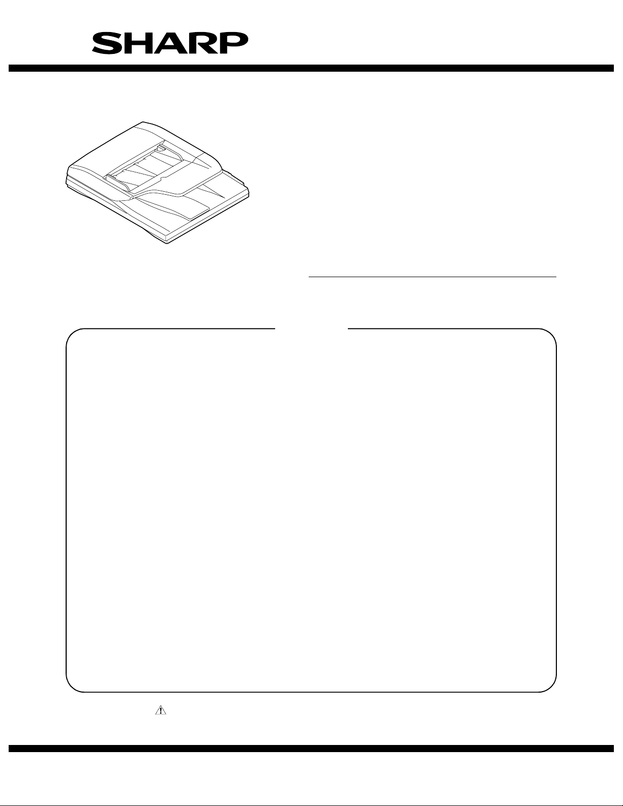
[1] PRODUCT OUTLINE
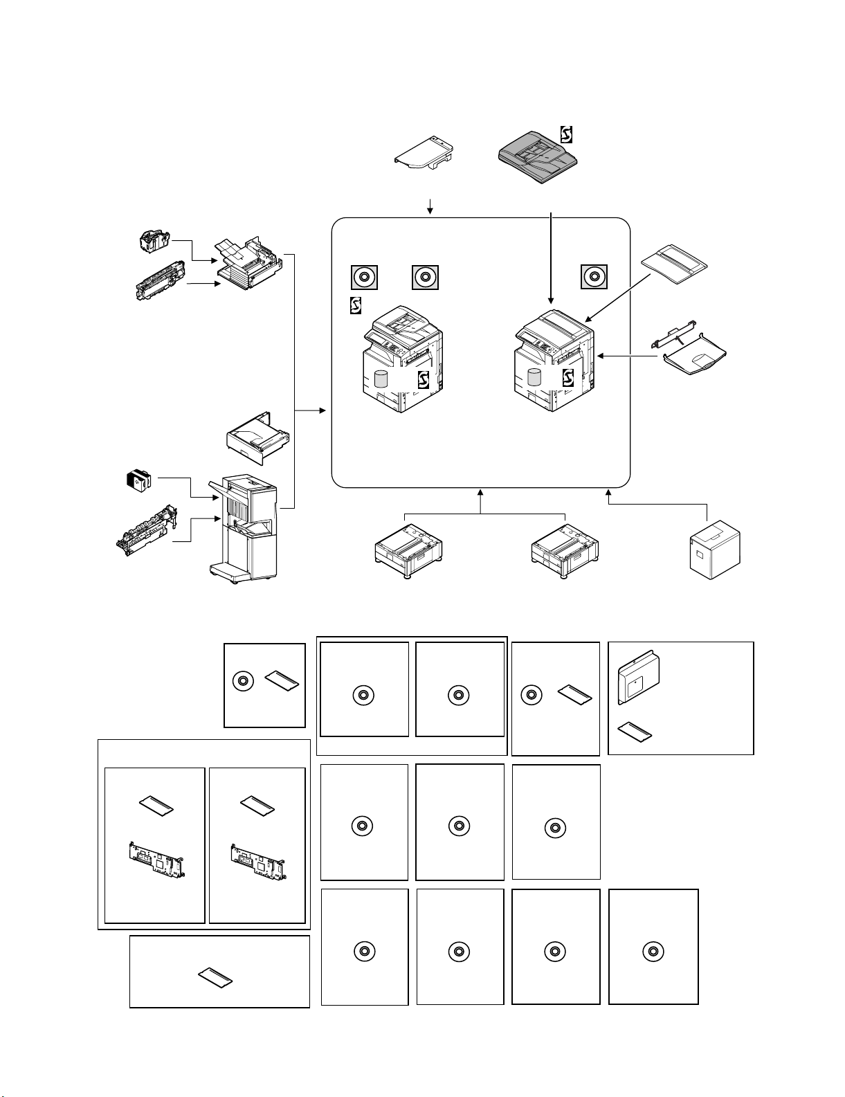
This product is the duplex auto document feeder unit to be installed
to a digital full color multifunctional system. It transports documents
automatically to perform continuous copying.
Service Manual
Staple cartridge
(Approx. 5000 x 3)
(MX-SCX1)
Punch module
●
2-hole (MX-PNX1A)
●
3-hole (MX-PNX1B)
●
4-hole (MX-PNX1C)
●
4-hole (broad space)
(MX-PNX1D)
Staple cartridge
(Approx. 5000 x 3)
(AR-SC2)
Punch module
●
2-hole (AR-PN1A)
●
3-hole (AR-PN1B)
●
4-hole (AR-PN1C)
●
4-hole (broad space)
(AR-PN1D)
(Including document control)
CC authentication
version
Security
ROM
For document
control PWB
(MX-FRX1)
Finisher
(MX-FNX1)
Paper pass unit
(MX-RBX1)
Saddle stitch finisher
(MX-FNX2)
Data security kit
Commercial
version
Barcode font kit
CD
ROM
(AR-PF1)
Security
ROM
For document
control PWB
(MX-FRX1U)
Device Tray with
USB Hub (MX-RKX1)
PCL5c/PCL6
driver
RSPF
HDD
Copier/Printer (PCL)
/Scanner model
(MX-2300N)
(MX-2700N)
Stand/1x500 sheet
paper drawer
(MX-DEX1)
Printer expansion
kit (PCL)
CD
(MX-PBX1)
(For MX-2300G/2700G)
Internet Fax
expansion kit
CD
(MX-FWX1)
Application
integration
module
Network
scanner
(Sharpdesk 1 license)
Network scanner
expansion kit
CD
(MX-NSX1)
Sharpdesk
1 license kit
Sharpdesk
5 license kit
CD
(MX-USX1/
USX5)
Sharpdesk
100 license kit
Reversing single pass feeder
(MX-RPX1)
SPLC-c
driver
HDD
Copier/Printer (SPLC-c)
model
(MX-2300G)
(MX-2700G)
Stand/2x500 sheet
paper drawer
(MX-DEX2)
PS3 expansion
kit
CD ROM
(MX-PKX1)
Sharpdesk
10 license kit
Sharpdesk
50 license kit
CD
(MX-US10/
US50)
Application
communication
module
External
account module
Document cover
(MX-VRX1)
Exit tray unit
(MX-TRX1)
Large capacity tray
(MX-LCX1)
Facsimile
expansion kit
(MX-FXX1)
FAX memory (8MB)
(packed together)
256MB expansion memory board
(MX-SMX1)
(For MX-2300G/2700G)
CD
(MX-AMX1)
CD
(MX-USA0)
MX-RPX1 PRODUCT OUTLINE 1 – 1
CD
(MX-AMX2)
CD
(MX-AMX3)
Page 4

[2] SPECIFICATIONS
Type RSPF (Duplex auto document feeder unit (reverse pass type))
Document set direction Face up
Paper feed type Take-up roller top feed
Paper exit type U-turn face down exit
Paper pass reference Center reference (Rear one-side standard for random feeding)
Document transport method Sheet-through method
Scan reference Left side when viewed from the front of the unit
Document size Inch type-1: 11" x 17", 8.5" x 14", 8.5" x 11", 8.5" x 11"R, 8.5" x 5.5", A3, A4
Document weight Single: 35 to 128g/m
Document set quantity 100 sheets (80g/m
Paper exit section load capacity Max. 100 sheets (80g/m
Copy magnification ratio 25 to 200%
External dimensions (W x D x H) 590 x 510 x 155 (mm), 23 15/64 x 20 5/64 x 6 7/64 (inch)
Weight Approx. 10kg (22.0 lbs)
Power source Supplied from the copier. (DC 3.3V, 5V, 24V)
Power consumption 35.8W
Document size detection Auto detection (The following 5 detection sizes can be selected by system setting.)
Detection size Inch-1: 11" x 17", 8.5" x 14", 8.5" x 11", 8.5" x 11"R, 5.5" x 8.5", A3, A4
Not-specified documents OHP, second original paper, tracing paper, carbon paper, thermal paper, paper with wrinkles, folds, or breakage, pasted paper,
Mixed kinds of documents Mixed sizes of paper feed allowed (Same width only)
Random paper feed Random paper feed allowed (Single face only)
Document reverse Provided
Document replacement speed 300dpi: Max. 48CPM (A4/LT cross-sectional feed) (248mm/s)
Installation/maintenance Installed by service personnel
Optional detection Auto detection supported
Packaged items Parts for mounting, installation cautionary note
Inch type-2: 11" x 17", 8.5" x 13", 8.5" x 11", 8.5" x 11"R, 8.5" x 5.5", A3, A4
AB type-1: A3, B4, A4, A4R, B5, B5R, A5, 11" x 17", 8.5" x 14", 8.5" x 11"
AB type-2: A3, B4, A4, A4R, B5, B5R, A5, 11" x 17", 8.5" x 11", 216 x 330
AB type-3: A3, B4, A4, A4R, A5, 8K, 16K, 16KR, 11" x 17", 8.5" x 11", 216 x 330
(The FAX function supports max. 800mm of long document.)
Duplex: 50 to 105g/m
Thickness: Max. 13mm, 1/2 inch
Inch-2: 11" x 17", 8.5" x 13", 8.5" x 11", 8.5" x 11"R, 5.5" x 8.5", A3, A4
AB-1: A3, B4, A4, A4R, B5, B5R, A5, 11" x 17", 8.5" x 14", 8.5" x 11"
AB-2: A3, B4, A4, A4R, B5, B5R, A5, 11" x 17", 8.5" x 11", 216 x 330
AB-3: A3, B4, A4, A4R, A5, 8K, 16K, 16KR, 11" x 17", 8.5" x 11", 216 x 330
torn document, documents with perforation other than 2- or 3-holes, document printed with ink ribbon, documents bound by
staple or clip, document with high surface friction such as photo or catalogue
(AB series: combinations of A3 and B4, B4 & A4R, A4 & B5, B5 & A5 only)
(Inch series: Combination of 8.5" width and 11" width only)
600dpi: Max. 35CPM (A4/LT cross-sectional feed) (157mm/s)
(Max. 27CPM (A4/LT cross-sectional feed) (124mm/s) * When MX-2300/2700 G/N is installed.)
2
(21 lbs))
2
(9 to 34 lbs)
2
(13 to 28 lbs)
2
(21 lbs))
Service Manual
MX-RPX1 SPECIFICATIONS 2 – 1
Page 5
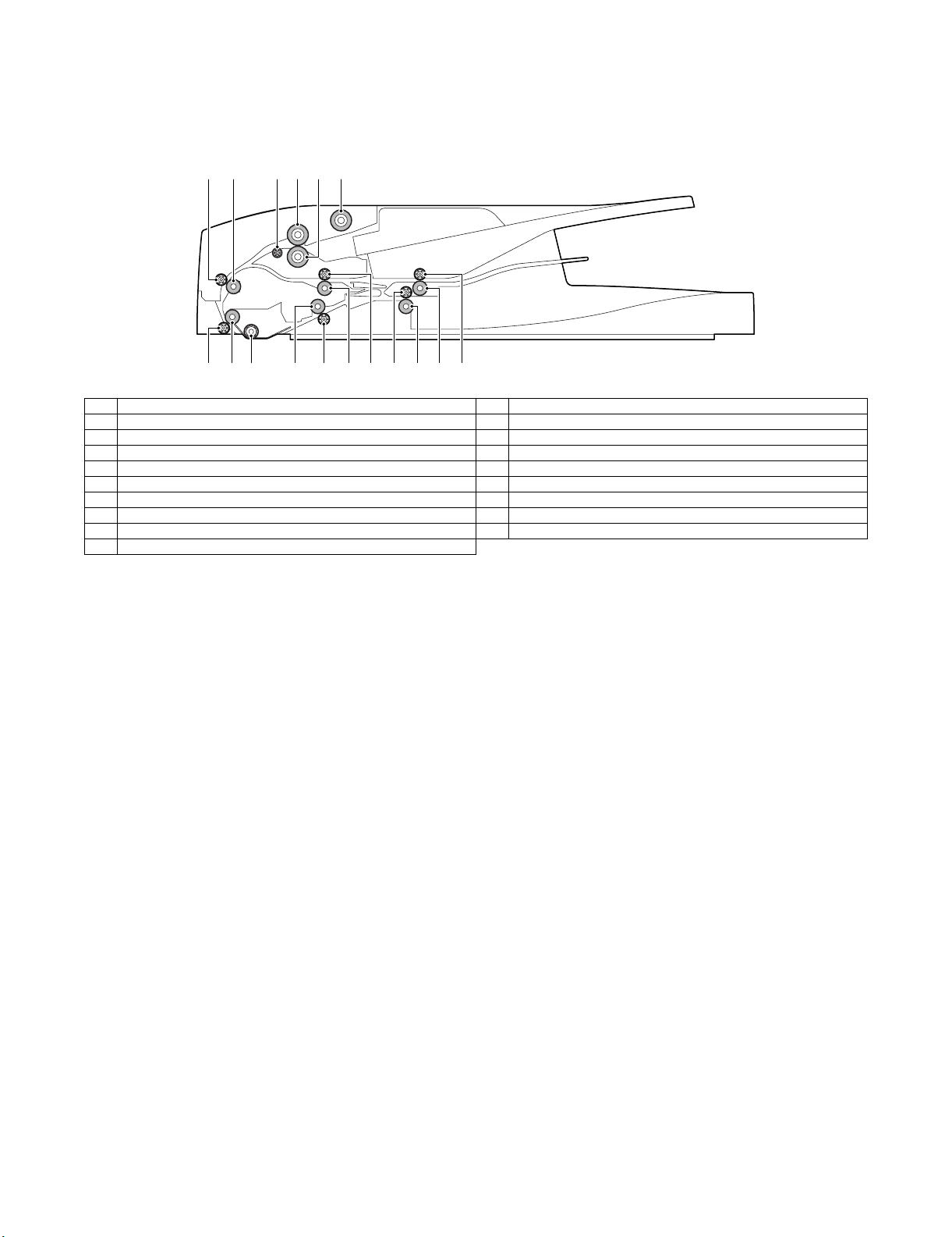
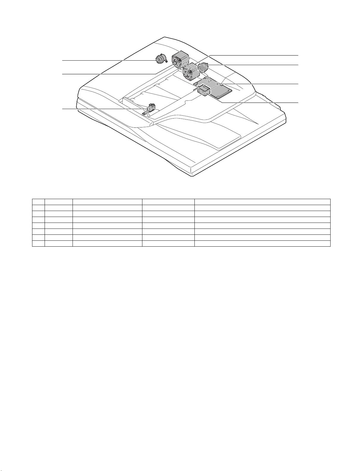
[4] EXTERNAL VIEW AND INTERNAL STRUCTURE
Service Manual
1. Identification and functions of each section
A. Internal structure
1
9 1187
10 1512 14 16 1713
246 3
5
No. Name No. Name
1 Pick-up roller 10 Scan rear roller
2 Paper feed separation roller 11 Transport follower roller
3 Separation roller 12 SWB pass section transport roller
4 U-turn roller 13 Transport follower roller
5 PS follower roller 14 Paper exit roller
6 PS roller 15 Paper exit follower roller
7 Transport follower roller 16 SWB roller
8 Scan front roller 17 Transport follower roller
9 Platen roller
MX-RPX1 EXTERNAL VIEW AND INTERNAL STRUCTURE 4 – 1
Page 6
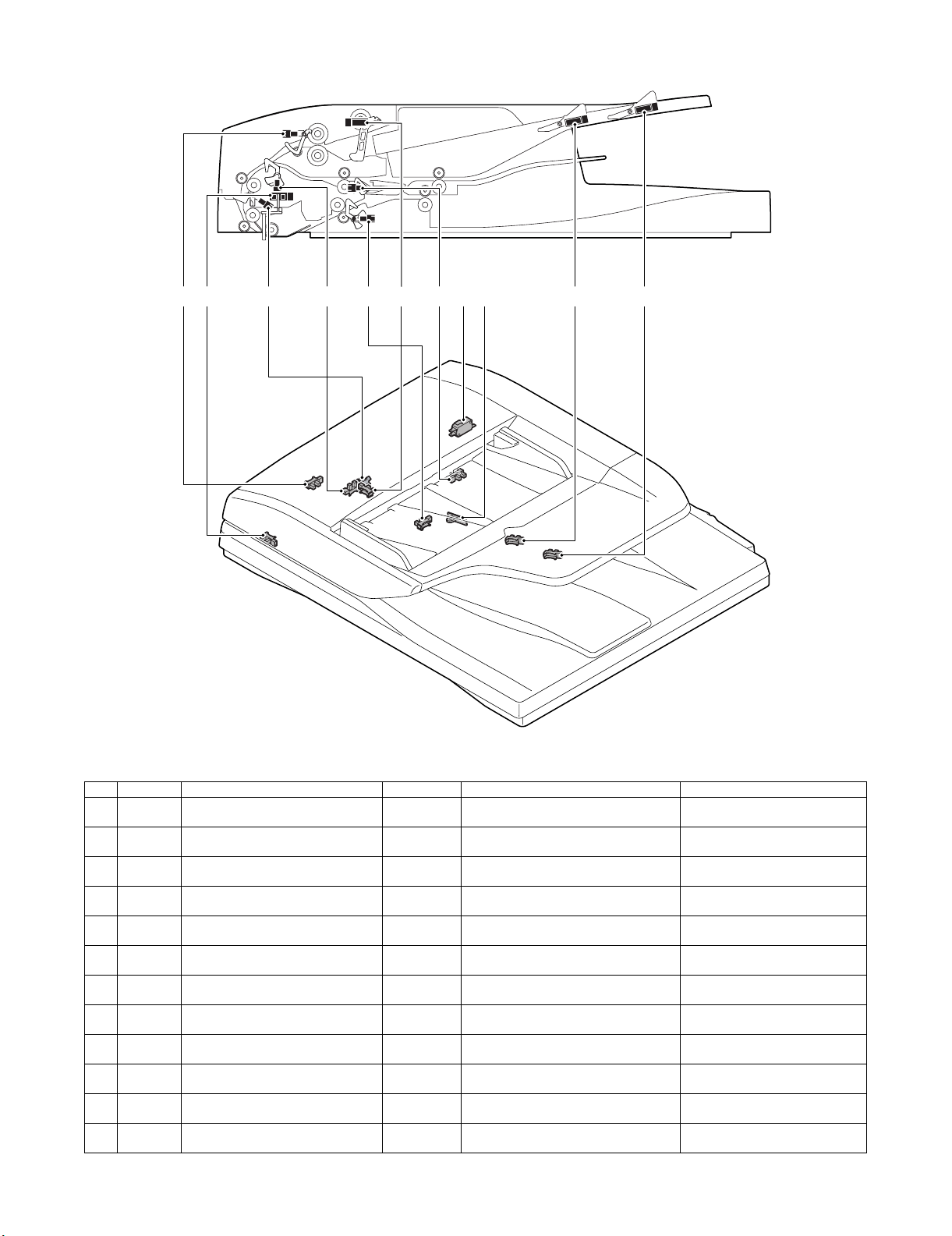
B. Sensors and switches
111092 5 874 3 6 1
No. Signal Name Type Function/operation Active condition
1 SCOV SPF cover SW Microswitch Detects open/close of the paper feed
2 SPPD1 SPF paper entry detection 1 sensor
(Commonly used for random detection)
3 SPPD2 SPF paper entry detection 2 sensor
(PS front)
4 SPPD3 SPF scan front sensor Transmission
5 SOCD SPF open/close sensor Transmission
6 SPPD5 SPF reverse rear sensor Transmission
7 SPPD4 SPF reverse gate front detection Transmission
8 SPED SPF document empty sensor Transmission
9 SPWS SPF document width sensor Volume
10 SPLS1 SPF document length short sensor Transmission
11 SPLS2 SPF document length long sensor Transmission
12 STMPU SPF stamp UN installation sensor – Detects installation of the finish stamp unit. H level when the finish stamp unit is
Transmission
type
Transmission
type
type
type
type
type
type
resistance
type
type
cover.
Detects paper entry and the paper size in
random feed.
Detects paper in front of the PS roller. H level when paper is detected.
Detects paper in front of the scan position. H level when paper is detected.
Detects open/close of the RSPF. L level when the RSPF is closed.
Detects reversed paper. H level when paper is detected.
Detects paper in front of the reverse gate. H level when paper is detected.
Detects paper empty on the tray. H level when paper is detected.
Detects the document width on the tray.
Detects the document length on the tray. H level when paper is detected.
Detects the document length on the tray. H level when paper is detected.
H level at cover open.
H level when paper is detected.
installed.
MX-RPX1 EXTERNAL VIEW AND INTERNAL STRUCTURE 4 – 2
Page 7
C. Motors, clutches, solenoids, and PWB
4
1
3
7
6
5
No. Signal Name Type Function/operation
1 SPFC SPF paper feed clutch Electromagnetic clutch Controls ON/OFF of the paper feed roller.
2 SPRM SPF paper feed reverse motor – Drives the paper feed system rollers and the SWB transport roller.
3 SPFM SPF transport motor – Drives the transport roller and the PS roller.
4 SRRC SPF resist roller clutch Electromagnetic clutch Controls ON/OFF of the resist roller.
5 STMPS Stamp solenoid – Drives the finish stamp.
6 SGS SPF document exit gate solenoid Electromagnetic solenoid Reverses the paper exit gate when ON.
7 – RSPF driver PWB – RSPF driver PWB
2
MX-RPX1 EXTERNAL VIEW AND INTERNAL STRUCTURE 4 – 3
Page 8
[5] OPERATIONAL DESCRIPTIONS
Service Manual
1. Document size detection
A. Document size detection
Size detection on the document tray
The document width is detected by the document width sensor
(SPWS), and the document length is detected by the document
length sensors (SPLS1, SPLS2). The document size is judged from
the document width and the document length as shown in the table
below.
When, however, mixed sizes of documents are loaded on the tray,
the maximum size is detected.
Document size
AB series A5 OFF OFF
B5 OFF OFF
11" x 8. 5" OF F O F F
A4 OFF OFF
B5R ON OFF
A4R ON OFF
8.5" x 13" ON ON
B4 ON ON
A3 ON ON
11" x 17" ON ON
Inch series 8.5" x 5.5" OFF OFF
11" x 8. 5" OF F O F F
A4 OFF OFF
11" x 8. 5"R O N OF F
8.5" x 13" ON ON
8.5" x 14" ON ON
A3 ON ON
11" x 17" ON ON
Document length sensor
SPLS1 SPLS2
2) Preliminary paper feed start (1st sheet)
The pick-up roller descends.
3) Preliminary paper feed complete/Paper feed start (1st sheet)
4) Resist operation (1st sheet)
5) Scanning start (1st sheet)
SPWS
SPLS1
SPLS2
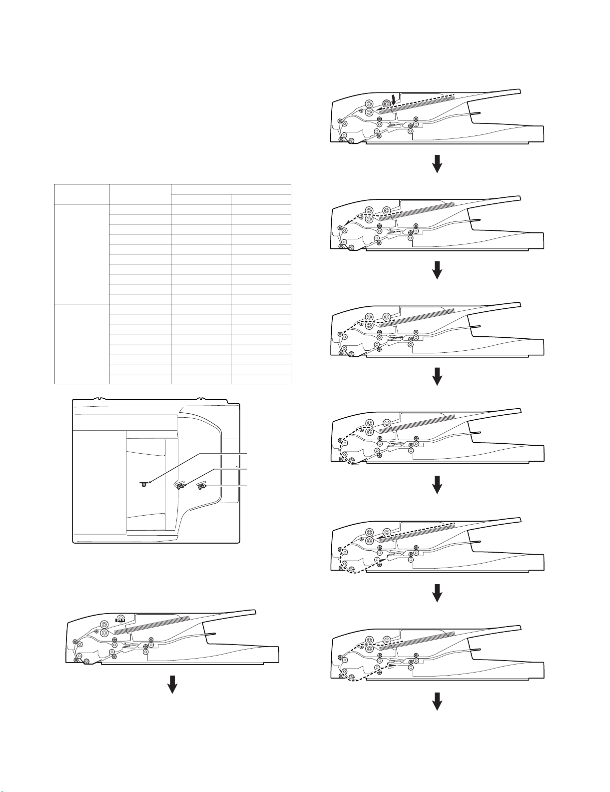
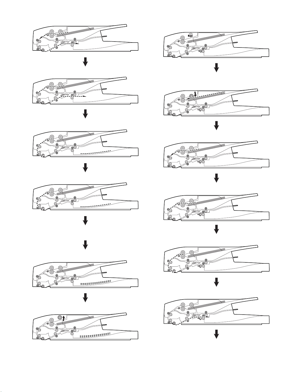
2. Paper feed and transport operations
A. Single face scanning
1) Document set (Document empty sensor ON)
6) Preliminary paper feed start (2nd sheet)
7) Preliminary paper feed complete (2nd sheet)
MX-RPX1 OPERATIONAL DESCRIPTIONS 5 – 1
Page 9
8) Paper feed start (2nd sheet)
9) Scanning complete (1st sheet)/Resist operation (2nd sheet)
10) Scanning start (2nd sheet)
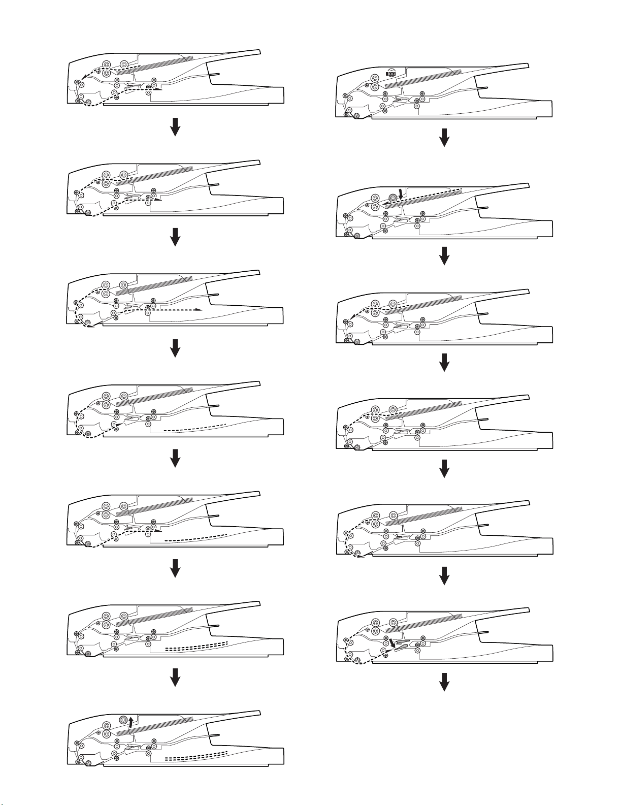
B. Duplex scanning
1) Document set (Document empty sensor ON)
2) Preliminary paper feed start (1st sheet)
Pick up roller descending
3) Preliminary paper feed complete/Paper feed start (1st sheet)
11) Paper exit complete (1st sheet)
12) Scanning complete (2nd sheet)
13) Paper exit complete (2nd sheet)
4) Resist operation (1st sheet, front surface)
5) Scanning start (1st sheet, front surface)
6) Gate descending (1st sheet, front surface)
14) Pick-up roller lifting up
MX-RPX1 OPERATIONAL DESCRIPTIONS 5 – 2
Page 10
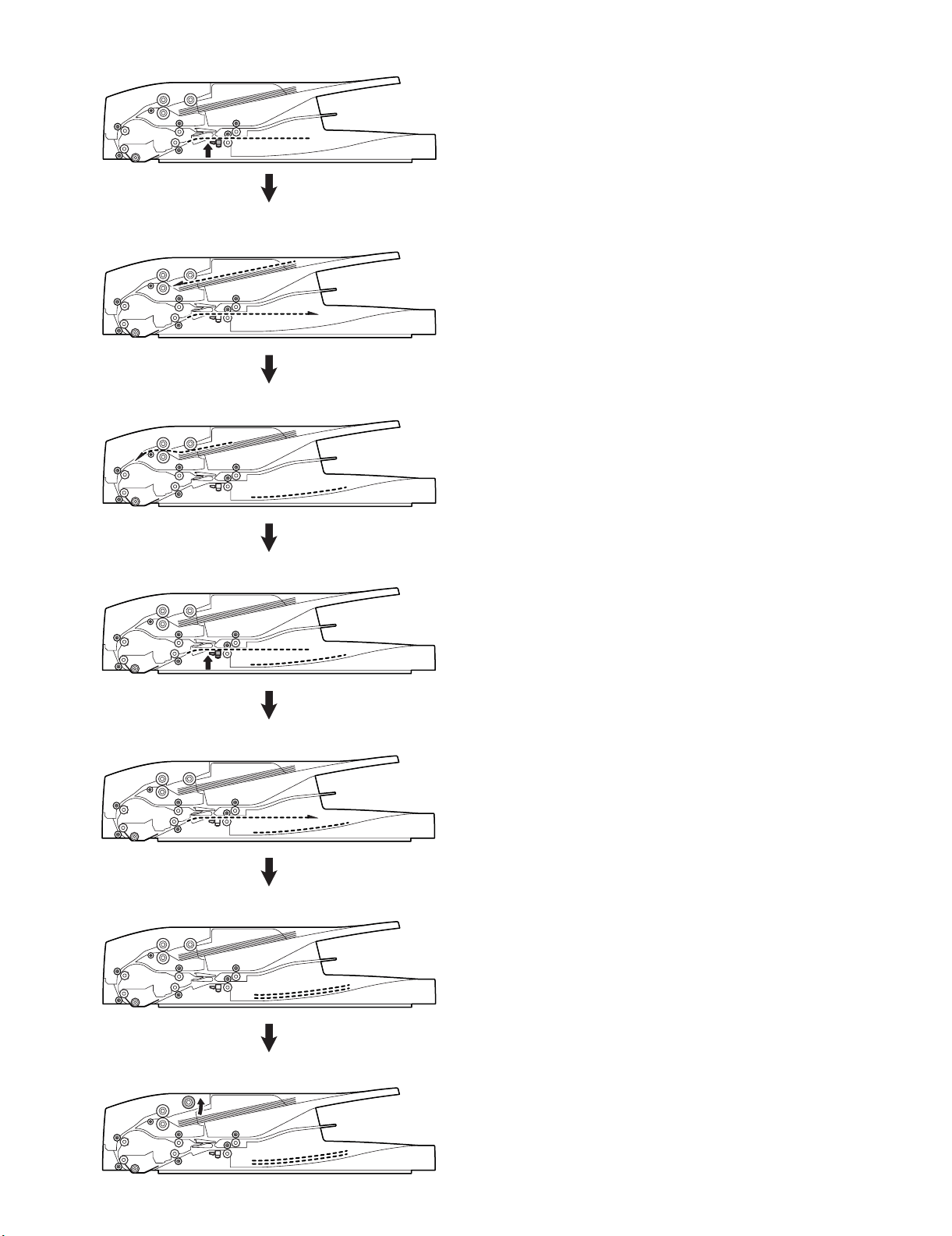
7) Scanning complete (1st sheet, front surface)
13) Gate descending (1st sheet, back surface)
8) Reverse stop
Gate lifting up
9) Reverse start
10) Resist operation after reverse
14) Scanning complete (1st sheet, back surface)
15) Reverse stop
Gate lifting up
16) Reverse start
11) Resist operation (1st sheet, back surface)
12) Scanning start (1st sheet, back surface)
17) Document transport continued
18) Preliminary paper feed start (2nd sheet)
MX-RPX1 OPERATIONAL DESCRIPTIONS 5 – 3
Page 11
19) Preliminary paper feed complete/Paper feed start (2nd sheet)
20) Resist operation (2nd sheet, front surface)
21) Paper exit complete (1st sheet)
C. Stamp operation
1) Document set (Document empty sensor ON)
2) Preliminary paper feed start (1st sheet)
Pick-up roller descending
3) Preliminary paper feed complete/Paper feed start (1st sheet)
22) Scanning start (2nd sheet, front surface)
23) Same operation as "5) Scanning start (1st sheet, front surface)" and later
24) Paper exit complete (2nd sheet)
25) Pick-up roller lifting up
4) Resist operation (1st sheet)
5) Scanning start (1st sheet)
6) Scanning complete (1st sheet)
MX-RPX1 OPERATIONAL DESCRIPTIONS 5 – 4
Page 12
7) Stop at the stamp position/Stamp operation (1st sheet)
8) Paper exit start (1st sheet)/Preliminary paper feed start (2nd
sheet)
9) Paper exit complete (1st sheet)
10) Stop at the stamp position/Stamp operation (2nd sheet)
11) Paper exit start (2nd sheet)
12) Paper exit complete (2nd sheet)
13) Pick-up roller lifting up
MX-RPX1 OPERATIONAL DESCRIPTIONS 5 – 5
Page 13
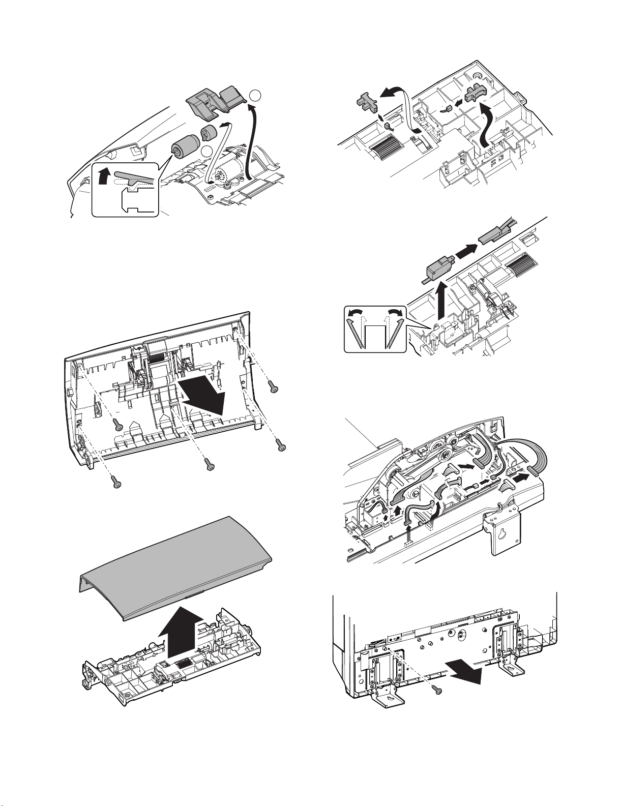
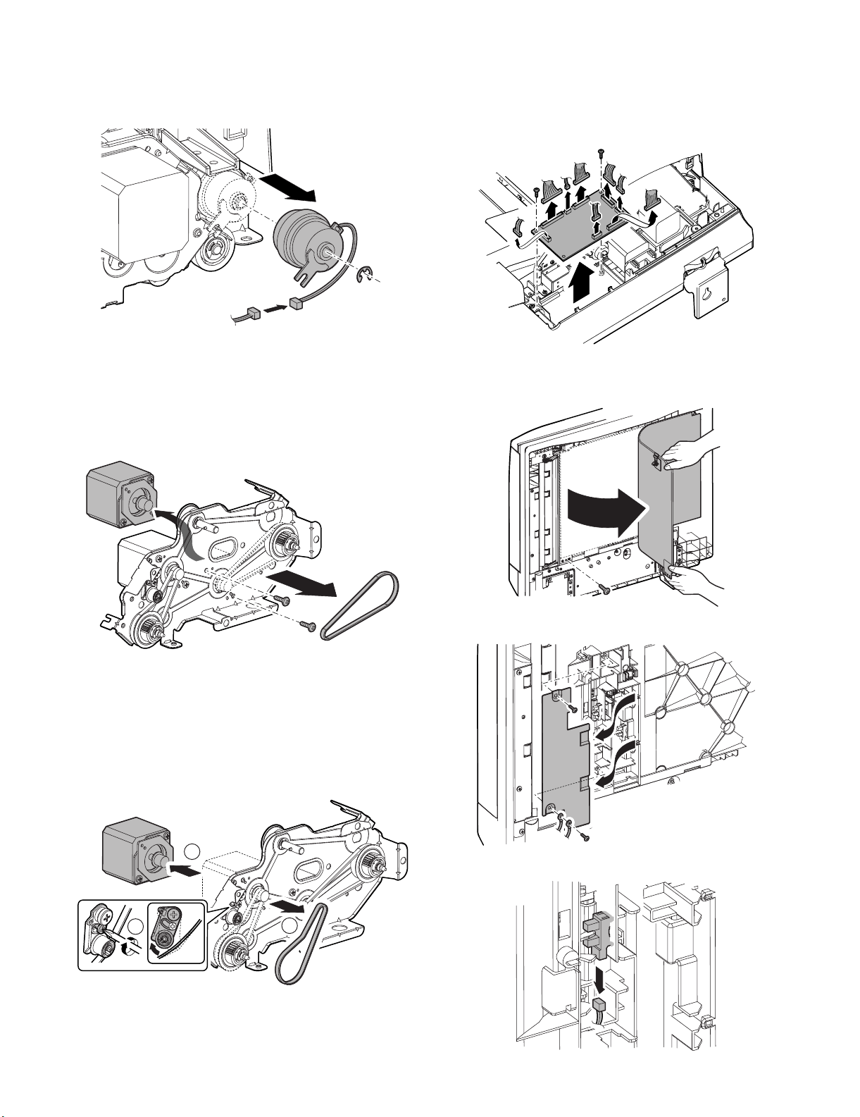
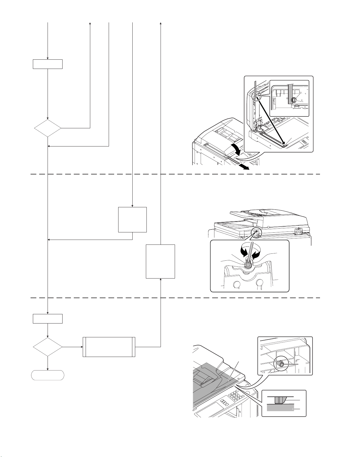
[6] DISASSEMBLY AND ASSEMBLY
Service Manual
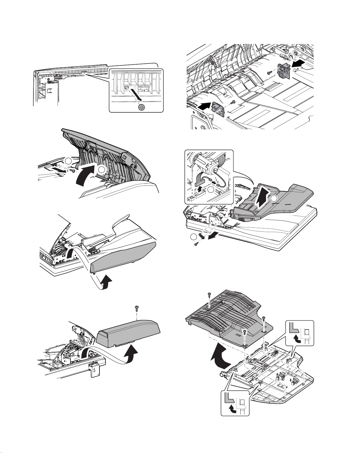
1. Document tray section
A. Document tray unit
1) Remove the RSPF unit bottom fixing screw.
2) Open the paper feed unit, and remove the screw.
2
1
3) Remove the front cabinet.
5) Remove the stopper.
6) Disconnect the connector. Remove the paper feed PG holder,
and remove the document tray unit.
1
3
4) Remove the screw, then remove the rear cabinet.
2
(1) SPF document length short sensor/SPF document
length long sensor/SPF document width sensor
1) Remove the document tray unit.
2) Remove the lower document tray.
MX-RPX1 DISASSEMBLY AND ASSEMBLY 6 – 1
Page 14
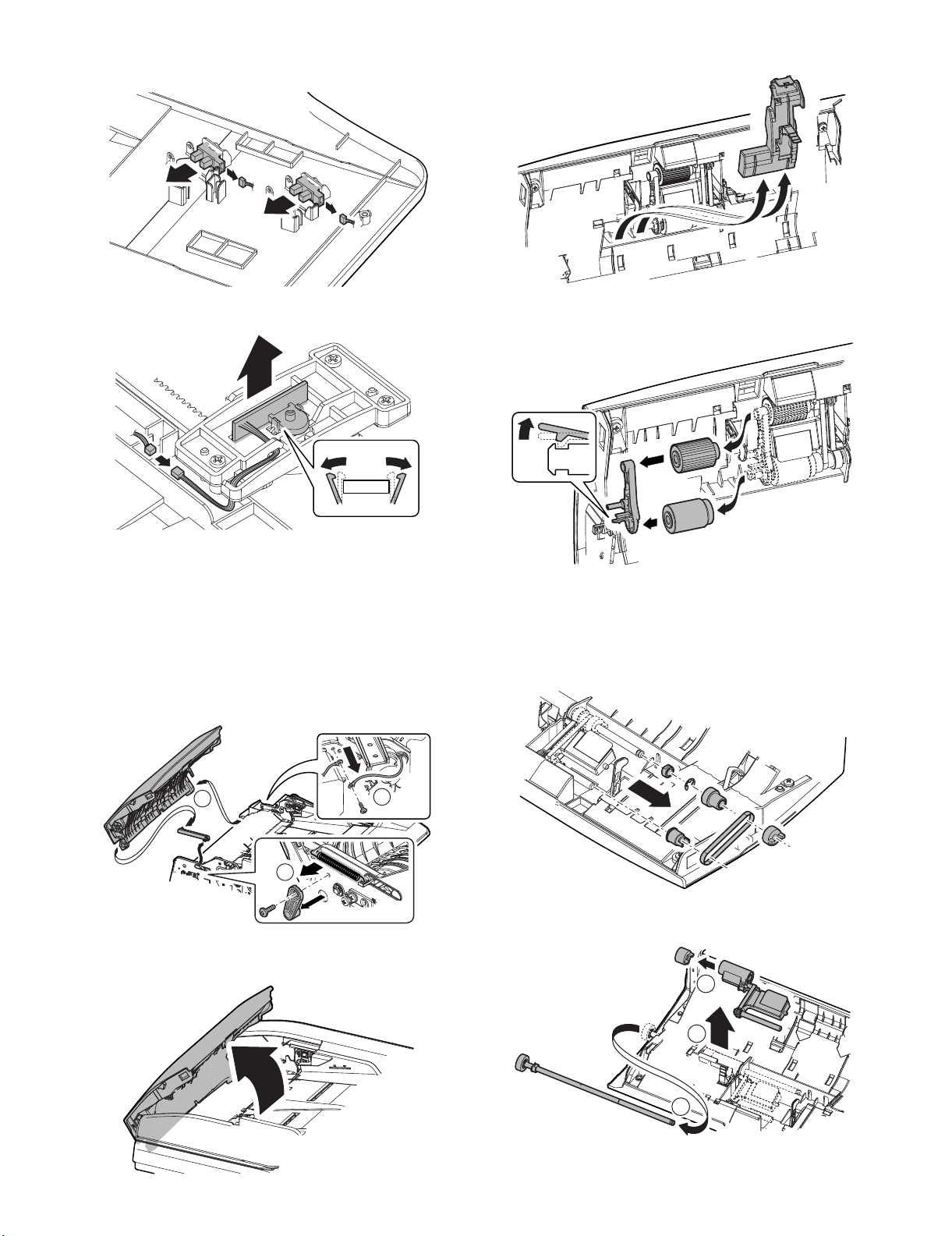
3) Remove the SPF document length short sensor and the SPF
document length long sensor.
2) Remove the upper transport auxiliary PG.
4) Remove the SPF document width sensor.
2. Paper feed section/paper transport
section
A. Paper feed unit
1) Remove the front cabinet and the rear cabinet.
2) Remove the transport unit.
3) Disconnect the grounding wire. Remove the spring, the paper
feed PG holder, and remove the paper feed unit and the upper
PG link arm.
3) Remove the holder guide, and remove the pick-up roller and
the paper feed roller.
(2) Take-up torque limiter
1) Remove the front cabinet and the rear cabinet.
2) Remove the paper feed unit.
3) Remove the pick-up roller and the paper feed roller.
4) Remove each part.
3
2
(1) Pick-up roller/Paper feed roller
1) Open the paper feed unit.
1
5) Remove the paper feed shaft, the pick-up roller holder, and the
take-up torque limiter.
3
2
1
MX-RPX1 DISASSEMBLY AND ASSEMBLY 6 – 2
Page 15
(3) Separation roller/Torque limiter SPF
1) Open the paper feed unit.
2) Remove the separation roller cover. Remove the separation
roller and the torque limiter SPF.
1
2
(4) SPF paper entry detection 1 sensor/SPF document
empty detection sensor/SPF cover switch
1) Remove the front cabinet and the rear cabinet.
2) Remove the transport unit.
3) Remove the paper feed unit.
4) Remove the screws.
6) Remove the SPF paper entry detection 1 sensor and the SPF
document empty sensor.
7) Remove the SPF cover switch.
5) Remove the upper cover.
B. Transport unit
1) Remove the front cabinet and the rear cabinet.
2) Disconnect the connector.
3) Remove the RSPF unit bottom fixing screws.
MX-RPX1 DISASSEMBLY AND ASSEMBLY 6 – 3
Page 16
4) Remove the screws.
2
2
3
1
1
5) Remove the transport unit.
(1) Platen roller
1) Clean the platen roller from the bottom of the RSPF unit.
(3) PS roller/Scan front roller
1) Remove the front cabinet and the rear cabinet.
2) Remove the paper feed unit.
3) Remove the transport unit.
4) Remove the PS clutch.
5) Remove the parts, and remove the PS roller and the scan front
roller.
2
3
1
(4) Scan rear roller
1) Remove the front cabinet and the rear cabinet.
2) Remove the transport unit.
3) Remove the document tray unit.
4) Remove the drive unit.
5) Loosen the screws. Remove the E-rings, and slide the bearing.
Remove the scan plate unit.
(2) SPF open/close sensor
1) Remove the front cabinet and the rear cabinet.
2) Remove the transport unit.
3) Remove the SPF open/close sensor mounting plate.
MX-RPX1 DISASSEMBLY AND ASSEMBLY 6 – 4
6) Remove the resin E-ring, and remove the JAM release knob
and the belt. Remove the bearing.
Page 17
7) Loosen the tension holder screw to loosen the belt tension,
and remove the parts.
2
1
8) Remove the scan rear roller, and remove the parts.
2
2
1
3. Paper exit section
A. Paper exit section parts
(1) Discharge brush
1) Remove the front cabinet and the rear cabinet.
2) Remove the transport unit.
3) Remove the discharge brush.
• Discharge brush attachment reference
Fit the discharge brush with the mark-up reference and
attach it.
(5) SPF paper entry detection 2 sensor/SPF scan front
sensor
1) Remove the front cabinet and the rear cabinet.
2) Remove the transport unit.
3) Remove the document tray unit.
4) Remove the drive unit.
5) Remove the scan plate unit.
6) Remove the sensor mounting plate.
(2) Paper exit roller
1) Remove the front cabinet and the rear cabinet.
2) Remove the transport unit.
3) Remove the document tray unit.
4) Remove the drive unit.
5) Remove the parts.
6) Remove the parts and remove the paper exit roller.
2
MX-RPX1 DISASSEMBLY AND ASSEMBLY 6 – 5
1
1
Page 18
4. Document reverse section
A. Reverse section parts
(1) SPF document exit gate solenoid
1) Remove the front cabinet and the rear cabinet.
2) Remove the transport unit.
3) Remove the solenoid adjustment plate. Remove the SPF document exit gate solenoid.
* When assembling, insert the pin of the SPF document exit
gate solenoid into the gate.
2
1
(3) SWB pass section transport roller/SPF reverse
rear sensor
1) Remove the front cabinet and the rear cabinet.
2) Remove the transport unit.
3) Remove the paper feed unit.
4) Remove the document tray unit.
5) Remove the drive unit.
6) Remove the separation roller.
7) Remove the separation transport PG.
(2) SWB roller
1) Remove the front cabinet and the rear cabinet.
2) Remove the transport unit.
3) Remove the document tray unit.
4) Remove the drive unit.
5) Remove the paper exit roller.
6) Remove the parts, and remove the intermediate tray unit.
1
1
2
7) Remove the intermediate tray PG. Remove the E-ring and the
bearing. Remove the SWB roller.
8) Remove the parts. Remove the separation shaft and the
spring.
2
3
1
1
9) Remove the intermediate PG.
1
3
MX-RPX1 DISASSEMBLY AND ASSEMBLY 6 – 6
2
Page 19

10) Remove the parts, and remove the SWB pass section trans-
1
2
3
3
port roller.
1
11) Remove the scan rear roller.
12) Remove the scan rear PG.
2
1
5. Drive section
A. Drive unit
1) Remove the front cabinet and the rear cabinet.
2) Remove the transport unit.
3) Remove the document tray unit.
4) Remove the resin E-ring and the bearing. Remove the drive
unit and the parts.
(1) Belts
1) Remove the front cabinet and the rear cabinet.
2) Remove the transport unit.
3) Remove the document tray unit.
4) Remove the drive unit.
13) Remove the SPF reverse rear sensor.
(2) SPF paper feed clutch
1) Remove the rear cabinet.
2) Remove the resin E-ring, and remove the SPF paper feed
clutch.
MX-RPX1 DISASSEMBLY AND ASSEMBLY 6 – 7
Page 20
(3) Resist roller clutch
1) Remove the front cabinet and the rear cabinet.
2) Remove the transport unit.
3) Remove the E-ring, and remove the SPF resist roller clutch.
(4) SPF paper feed reverse motor
1) Remove the front cabinet and the rear cabinet.
2) Remove the transport unit.
3) Remove the document tray unit.
4) Remove the drive unit.
5) Remove the SPF paper feed reverse motor.
6. Base tray section
A. Base tray section parts
(1) RSPF driver PWB
1) Remove the rear cabinet.
2) Remove the RSPF driver PWB.
(2) SPF reverse gate front sensor
1) Remove the screw, and peel off the OC mat.
(5) SPF transport motor
1) Remove the front cabinet and the rear cabinet.
2) Remove the transport unit.
3) Remove the document tray unit.
4) Remove the drive unit.
5) Loosen the tension holder screw to loosen the belt tension.
Remove the SPF transport motor.
2
1
2
2) Remove the sensor cover.
3) Remove the SPF reverse gate front sensor.
MX-RPX1 DISASSEMBLY AND ASSEMBLY 6 – 8
Page 21
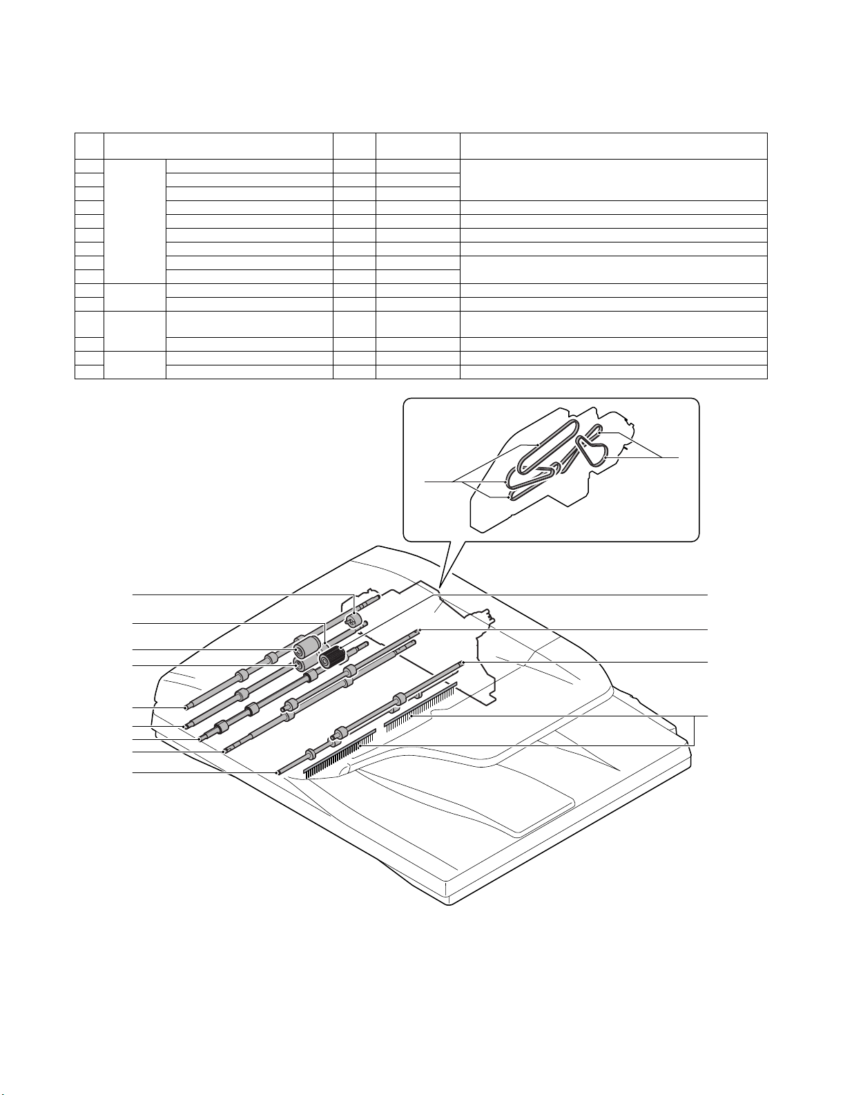
[7] MAINTENANCE
Service Manual
1. Maintenance system table
✕: Check (Clean, replace, adjust if necessary.) {: Clean ▲: Replace U: Adjust ✩: Lubricate : Shift position
No. Part name
1 Paper feed/
transport
2 Pick-up roller {{
section
3 Separation roller {{
4 PS roller (Drive) {{
5 Scan front roller (Drive) {{
6 Platen roller (Drive) {{
7 Scan rear roller (Drive) {{
8 Torque limiter SPF (for separation) ✕✕Replacement reference: RSPF document feed 400K (SIM22-8), or
9 Take-up torque limiter (for pick up) ✕✕
10 Paper exit
section
11 Discharge brush ✕✕
12 Reverse
section
13 SWB roller (Drive) {{
14 Drive
section
15 Belts ✕
Paper feed roller {{Replacement reference: RSPF document feed 100K (SIM22-8), or
Paper exit roller SPF {{
SWB pass section transport roller
(Drive)
Gears ✕✕
When
calling
Follows the
main unit cycle.
after 1 year of use
after 2 years of use
{{
Remark
15
15
9
8
1
3
4
5
6
7
10
2
13
12
11
MX-RPX1 MAINTENANCE 7 – 1
Page 22
A
K
0
A
:
A㧦 99
B㧦 50
㧧 OC
㧧 SPF(SIDE1)
SIMULATIONNO.50-12
ORGINAL CENTER OFFSET SETUP
99
㨇 1㨪 99 㨉
OK
TEST
CLOSE
C㧦 50 㧧 SPF(SIDE2)
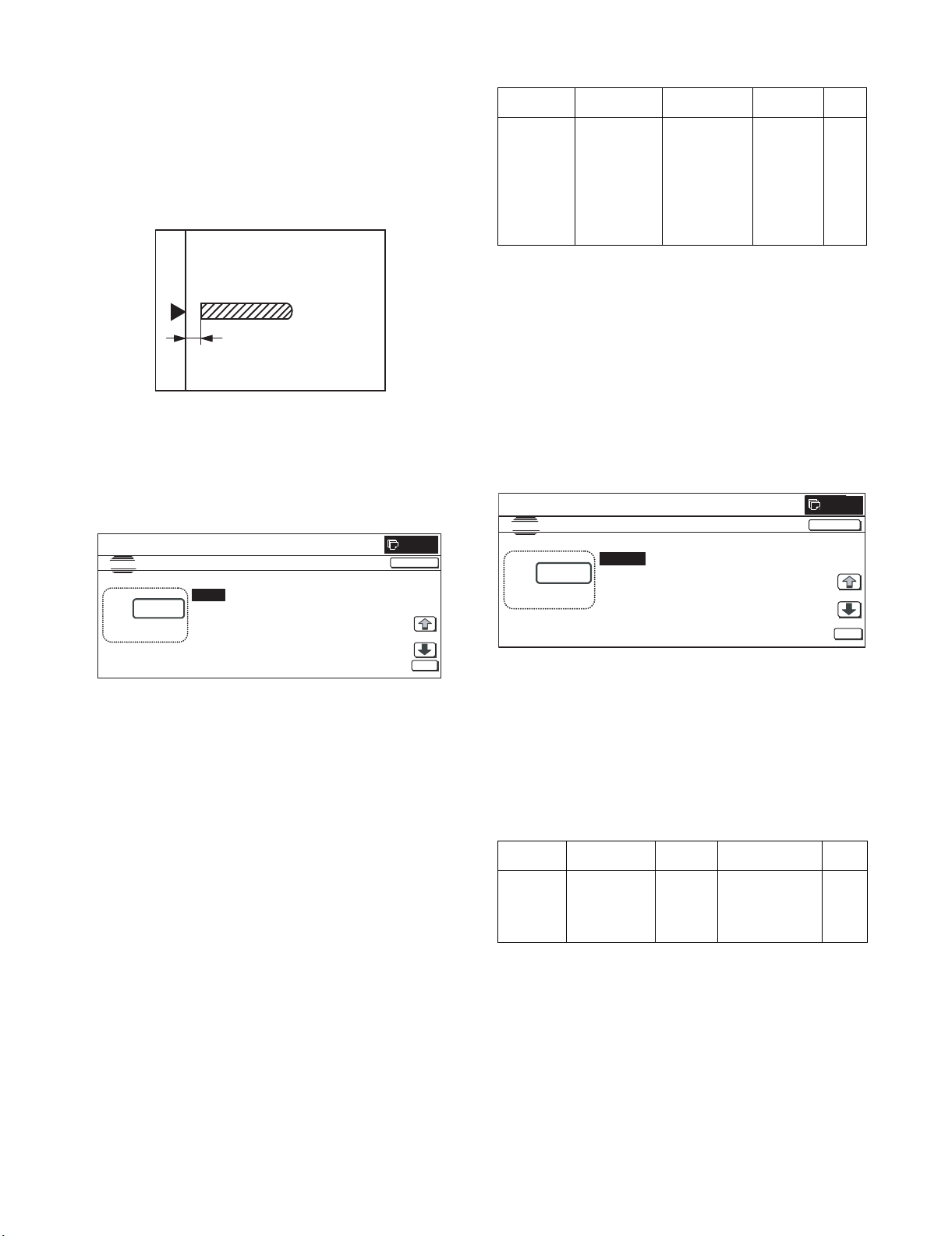
[8] ADJUSTMENTS
<Adjustment specifications>
Service Manual
1. RSPF magnification ratio adjustment
NOTE: To execute this adjustment, the CCD unit must have been
properly installed. To execute this adjustment, the OC
mode adjustment when copying must have been completed.
1) Place a scale on the document table as shown in the figure
below, and make a normal copy to make a test chart.
Note: Since the copied scale is used as a test chart,
place the scale in parallel to the sides.
2) Set the test chart on the RSPF, and make a normal copy.
3) Compare the outputted copy with the test chart. If it is judged
from comparison that an adjustment is required, perform the
following procedures.
4) Execute SIM48-1.
SIMULATIONNO.48-01
TEST
MAGNIFICATION ADJUSTMENT
:
㨇 1㨪99 㨉
80
A㧦 80
B㧦 50
C㧦 50
D㧦 50
㧧 CCD(MAIN)
㧧 CCD(SUB)
㧧
SPF(MAIN)
㧧
SPF(SUB)
0
CLOSE
Mode Specifications SIM Set value
Magnification
ratio
adjustment
Normal ±1.0% SIM48-1
<Main scanning
direction>
C: Front surface
E: Back surface
<Sub scanning
direction>
D: Front surface
F: Back surface
Add 1: 0.1%
enlarged.
Subtract 1:
0.1%
reduced.
Default: 50
Set
range
1 – 99
2. RSPF document off-center adjustment
NOTE: To execute this adjustment, the paper off-center must have
been adjusted properly.
1) Set the test chart for center position adjustment (which is
made by yourself) on the RSPF.
<Adjustment specifications>
Draw a straight line on paper in the scanning direction.
2) Make a normal copy from the manual paper feed tray. Com-
pare the printed copy and the test chart. If an adjustment is
required, perform the following procedures.
3) Execute SIM50-12.
㩷㩷
5) Change the mode to "C: SPF (MAIN)." The current magnification ratio correction value is displayed in 2 digits on the display
section.
6) Enter a set value and press [OK] key. The correction value is
saved and a copy is made.
7) Change the mode to "E: SPFB (MAIN)." The current magnification ratio correction value is displayed in 2 digits on the display section.
8) Enter a set value and press [OK] key. The correction value is
saved and a copy is made.
9) Change the mode to "D: SPF (SUB)." The current magnification ratio correction value is displayed in 2 digits on the display
section.
10) Enter a set value and press [OK] key. The correction value is
saved and a copy is made.
11) Change the mode to "F: SPFB (SUB)." The current magnification ratio in the back surface sub scanning direction is displayed in 2 digits on the display section.
12) Enter a set value and press [OK] key. The correction value is
saved and a copy is made.
O
MX-RPX1 ADJUSTMENTS 8 – 1
4) Change the mode to "B: SPF (SIDE1)." The current off-center
adjustment value is displayed in 2 digits on the display section.
5) Enter a set value and press [START] key. The correction value
is saved and a copy is made.
6) Change the mode to "C: SPF (SIDE2)." The current back surface off-center adjustment value is displayed in 2 digits on the
display section.
7) Enter a set value and press [OK] key. The correction value is
saved and a copy is made.
<Adjustment specifications>
Mode Specifications SIM Set value
Document
off-center
adjustment
Center position
(Default): 3750
pixel
SIM50-12
B: Front
surface
C: Back
surface
Add 1: Shift to R
side by 0.1mm.
Subtract 1: Shift to
F side by 0.1mm.
Set
range
1 – 99
Page 23

3. RSPF copy image position, void area
A
image adjustment
1) Place a scale on the OC table as shown in the figure below.
Note: Since the copied scale is used as a test chart,
place the scale in parallel to the sides.
2) Make a copy. Use the output copy as the original document,
and make a copy of it from the RSPF.
3) Check the output result. If an adjustment is required, perform
the following procedures.
4) Execute SIM50-6.
0
SIMULATIONNO.50-06
TEST
LEAD EDGE ADJUSTMENT VALUE(RSPF)
:
㨇 1㨪 99 㨉
26
A㧦 26
B㧦 50
C㧦 15
D㧦 20
㧧 SIDE1
㧧 SIDE2
㧧 LEAD ED GE
㧧 FRONT_ REAR
CLOSE
4. RSPF scan position adjustment
1) Enter SIM53-08 mode, and press [OK] button.
<<Description of adjustment display>>
Set
Item Display item Description
A ADJUST VALUE RSPF scan position
adjustment
• When the set value is increased by 1, the distance from the
home position to the RSPF scan position is increased.
• When the set value is changed by 1, the position is shifted
by 0.1mm.
* Since the SPF scan position distance are changed, RRCA is
not changed by the adjustment value.
[Note]
• After completion of the RSPF scan position adjustment, execute the RSPF lead edge adjustment (for both sides).
2) Check to confirm that the lead edge is not shifted. (Both surfaces) (If the original lead edge adjustment is proper, the scan
position after change automatically follows.)
Default
range
1 – 99 50
value
OK
5) Set the RSPF lead edge position set value so that an image
similar to the image adjusted in the previous OC image lead
edge position is outputted.
<<Set range and default value of each set value>>
Set
Item Display item Descriptions
A SIDE1 Front surface
B SIDE2 Back surface
C Image
loss
quantity
setting,
D FRONT_REAR
SIDE1
E TRAIL_EDGE
F Image
loss
quantity
setting,
G FRONT_REAR
SIDE2
H TRAIL_EDGE
LEAD_EDGE
(SIDE1)
(SIDE1)
(SIDE1)
LEAD_EDGE
(SIDE2)
(SIDE2)
(SIDE2)
document scan
start position
adjustment (CCD)
document scan
start position
adjustment (CCD)
Front surface lead
edge image loss
quantity setting
Front surface side
image loss
quantity setting
Front surface rear
edge image loss
quantity setting
Back surface lead
edge image loss
quantity setting
Back surface side
image loss
quantity setting
Back surface rear
edge image loss
quantity setting
Default
range
1 – 99 50
1 – 99 50
0 – 99 30
0 – 99 20
0 – 20 0
0 – 99 30
0 – 99 20
0 – 20 0
value
A, B: The greater the value is, the slower the scanning timing is.
C – H: The greater the adjustment value is, the greater the image
loss is.
A – H: 1 step = 0.1mm
The SPF rear edge image loss is provided against the shade. The
default value is 0.
MX-RPX1 ADJUSTMENTS 8 – 2
Page 24
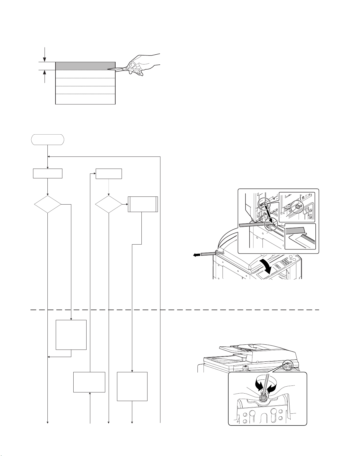
5. RSPF height adjustment
1) Make an RSPF height adjustment sheet
Cut copy paper in the longitudinal direction.
20mm
A4/Letter size
2) Perform the adjustment according to the flowchart below.
Start of the
adjustment
Check section A.
Check section
A again.
<Work procedure><Flow chart>
a) Check section A.
Place the RSPF height adjustment sheet between section A
and the SPF glass height adjustment resin surface (a), and
close the RSPF unit.
Slowly pull out the RSPF height adjustment sheet.
Check to insure that a slight resistance is felt when pulling out
the RSPF height adjustment sheet.
Be careful not to cover the convex section of the glass
*
holding resin surface with the height adjustment sheet.
No
Is
there a resist-
ance?
Yes Yes
Adjust hinge D
until there is a
resistance in
section A.
(Counterclockwise)
Is
there a resist-
ance?
No
The height on
the right side
is not proper.
A
a
If it cannot be pulled out or there is no resistance to pull out,
b)
turn section D to adjust.
Turn section D clockwise to lift the RSPF unit. Turn it
*
counterclockwise to move down the RSPF unit.
Adjust hinge
D until there is
a resistance in
section B.
Adjust hinge
D until there is
a resistance in
section A.
(Counterclockwise)
D
MX-RPX1 ADJUSTMENTS 8 – 3
Page 25
Check section B.
Is
there a re-
sistance?
Yes
No
Adjust hinge E
until there is a
resistance in
section B.
(Clockwise)
c) Check section B.
Place the RSPF height adjustment sheet between section B
and the SPF glass height adjustment resin surface (a), and
close the RSPF unit.
Slowly pull out the RSPF height adjustment sheet.
Check to insure that a slight resistance is felt when pulling out
the RSPF height adjustment sheet.
Be careful not to put the book sensor (b) on the height
*
adjustment sheet.
a
If it cannot be pulled out or there is no resistance to pull out,
d)
turn section E to adjust.
Turn section E clockwise to lift the RSPF unit. Turn it
*
counterclockwise to move down the RSPF unit.
B
b
Check section C.
Is there
a separating
section.
Yes
End of the
adjustment
No
The bosses in section A
and B are excessively
pressed. (The right side
is separating.)
Adjust hinge E
until the
separation in
section C is
deleted.
(Counterclockwise)
E
e) Check section C.
Check to confirm that the projection in section C in the right
front side of then RSPF bottom is in contact with the glass
surface (b).
b
C
C
b
MX-RPX1 ADJUSTMENTS 8 – 4
Page 26

6. RSPF diagonal adjustment
1) Set a test chart (A3) on the RSPF document tray, and make a
copy.
2) Measure (a) and (b) on the copied test chart. If (a) – (b) =
±1mm or more, perform the diagonal adjustment.
a
TEST CHART
A3 size
b
* In the case of (A), turn the RSPF diagonal adjustment screw
counterclockwise.
In the case of (B), turn the RSPF diagonal adjustment screw
clockwise.
A
B
3) Remove the hex nut cover in the RSPF diagonal adjustment
screw section.
4) Raise the RSPF unit upright, and loosen the fixing screw of the
hinge.
2
2
5) Close the RSPF unit, and loosen the hex nut of the RSPF
diagonal adjustment screw section.
Turn the hex wrench of the RSPF diagonal adjustment screw
to adjust the alignment.
2
1
3
1
6) Make a copy again and measure (a) and (b) on the copied test
chart. Repeat procedures 2) to 5) until the condition ((a)(b)=±1mm or less) is satisfied.
7) Tighten the hinge section fixing screw which was loosened in
the procedure 4) to tighten the hinge section.
7. SPF size width detection level
adjustment
1) Go to SIM53-6.
2) Set the tray document guide to the max. width position, and
press [EXECUTE] key. The button is highlighted and the tray
size volume maximum value adjustment is started.
* During the adjustment, "EXECUTING..." is displayed.
* After completion of the tray size volume maximum value
adjustment, the set value is saved to EEPROM and RAM
and the display is shifted to the tray volume A4R size adjustment value start screen. (Each set value is saved to
EEPROM and RAM at each setting.)
3) Set the tray document guide to A4R (11 x 8.5R) width position
and press [EXECUTE] button. The pressed button is highlighted and the tray A4R size adjustment is started.
4) Adjust the tray volume A5R (8.5 x 5 1/2R) size and the tray
size volume minimum value according to the above procedures.
5) After completion of the adjustment, "COMPLETE" is displayed.
If the adjustment is not completed normally for any reason,"ERROR"is displayed. In that case, the adjustment must
be executed again.
MX-RPX1 ADJUSTMENTS 8 – 5
Page 27

<Adjustment item and content>
No. Display Content
1 TRAYVOLMAX Tray size volume maximum value
2 TRAYVOLA4R Tray volume A4R size adjustment value
3 TRAYVOLA5R Tray volume A5R size adjustment
4 TRAYVOLMIN Tray size volume minimum value
When one of 1-4 in the above table is selected, the guide plate is
shifted to each position of the four widths of the guide plate shown
in the table below. The value of the document width sensor
(RSPF_WIDTH) A/D value is saved to EEPROM.
<Guide plate positions and widths on the mechanism and A/D
values to be saved>
Guide plate
No.
position
1 Maximum
position
2Middle
position (L)
3Middle
position (S)
4 Minimum
position
Widths on the mechanism A/D value,
AB
INCHI
series
series
299 299 WIDTH_MAX AD_MAX
210 21 5.9 WIT H_P1 AD_P1 A4R OR
148.5 139.7 WITH_P2 AD_P2 A5 R OR
118 118 WITH_MIN AD_MIN
Code in the
figure below
code in
the figure
below
Remark
LTR
INVR
[Initial screen]
0
SIMULATION NO.53-06
TEST
SPF TRAY ADJUSTMENT
TRAYVOLMAX TRAY ADJUSTMENT.
PRESS [EXECUTE] TO START
CLOSE
EXECUTE
8. Auto void adjustment (SPF adjustment)
1) Go to SIM50-28.
0
SIMULATION NO.50-28
TEST
AUTO IMAGE POSITION ADJUSTMENT: SERVICE
OC ADJ BK-MAG ADJ
SPF ADJ
RESULT DATA
SETUP/PRINT ADJ
CLOSE
4) Select one of the cassettes that can be used to print SPF
adjustment patterns.
5) Press the [EXECUTE] button, and the machine starts self-print
of SPF adjustment patterns.
* The screen shows a message indicating that the machine is
self-printing SPF adjustment patterns.
When self-print finishes, the next screen appears where you
can start SPF adjustments.
6) SPF adjustment patterns are loaded into the SPF.
* By pressing the [REPRINT] button, you can return to the
cassette selection screen and have the machine self-print
SPF adjustment patterns again.
7) Press the [EXECUTE] button, and the machine starts reading
SPF adjustment patterns (for the front side).
* The screen shows a message indicating that the machine is
reading and calculating SPF adjustment patterns (for the
front side).
The machine starts calculating the adjustment amount (for
the front side) after it has read the patterns for the front side.
After the machine has finished calculating the adjustment
amount for the front side, the next screen appears where
you can have the machine start reading SPF adjustment
patterns (for the back side).
<Adjustment Item List>
• SPF original leading edge adjustment (front side)
• SPF original off-center adjustment (front side)
• SPF original sub-scan magnification adjustment (front side)
8) SPF adjustment patterns are loaded into the SPF.
1/1
2) Press the [SPF ADJ] button.
0
SIMULATION NO.50-28
TEST
AUTO IMAGE POSITION ADJUSTMENT:SERVICE
SIDE1
ALL
SIDE2
CLOSE
1/1
3) Proceed to one of the three screens for selecting the cassette
used to print SPF adjustment patterns by selecting the corresponding button:
SIDE1: SPF adjustment for the front side
SIDE2: SPF adjustment for the back side
ALL: SPF adjustment for both the front and back sides
MX-RPX1 ADJUSTMENTS 8 – 6
* By pressing the [REPRINT] button, you can return to the
cassette selection screen and have the machine self-print
SPF adjustment patterns again.
Page 28

9) Press the [EXECUTE] button, and the machine starts loading
SPF adjustment patterns (for the back side).
* The screen shows a message indicating that the machine is
reading SPF adjustment patterns (for the back side).
The machine starts calculating the adjustment amount (for
the back side) after it has read the patterns for the back side.
After the machine has finished calculating the adjustment
amount for the back side, the next screen appears where
you can view the results of the adjustments.
<Adjustment Item List>
• SPF original leading edge adjustment (back side)
• SPF original off-center adjustment (back side)
• SPF original sub-scan magnification adjustment (back side)
10) The adjustment result screen appears.
This screen shows the current values along with the previous
values in parentheses.
* By pressing the [REPRINT] button, you can return to the
cassette selection screen and have the machine self-print
SPF adjustment patterns (for the front and back sides)
again.
* To have the machine start re-reading the SPF adjustment
patterns (front and back sides), press the [RESCAN] button.
* To return to the top menu without saving the adjustment val-
ues into EEPROM and RAM, press the [RETRY] button.
* To display the data used for adjustment, press the [DATA]
button.
11) To save the adjustment values into EEPROM and RAM and
return to the top menu, press the [OK] button.
* To return to the result screen, press the [BACK] button.
MX-RPX1 ADJUSTMENTS 8 – 7
Page 29

[10] ELECTRICAL SECTION
1. Electrical mechanism diagram
A. Paper feed section
CN-H
B6B-PH-K-R(RED)
CN-E
B11B-PH-K-S
+24VPD_SRRC
SRRC/
SPED
GND
+5V_SPED
+5VPD
SPPD1
GND
+24VPD
GND
+24VPD_SW
RSPF DRIVER
PWB
SPRMA/
+24VPD
SPRMA
SPRMB
+24VPD
SPRMB/
1
2
3
4
5
6
1
2
PHNR-8-H
3
4
5
6
7
8
9
10
11
PHNR-08-H
7182
6
554
4
3
2
1
BU08P-TR-P-H(LF)
179228-3
SPED
PHR-3
3 +5VPD
2
1 GND
PS-187-2V
1
2 +24VPD_SW
GND12
+5V_SPED3
SPPD1
+24VPD
3
6
7
8
SPPD1
SPED
Service Manual
A/
OR
+24V
BL
BR A
B
RE
+24V
WH
YE
B/
SCOV
SPWS
SPLS1
SPRM
SPFC
SPLS2
CN-D
B12B-PH-K-S
SPLS1
GND
+5VPD_LPLS1
SPLS2
GND
+5VPD_SPLS2
AVCC
SPWS
GND
SPFC/
GND
+24VPD_SW_SPFC
1
2
3
4
5
6
7
8
9
10
11
12
B. Reverse section
SMP-02V-BC
1221
SMR-02V-B
PHNR-03-H
BU03P-TR-P-H(LF)
PHNR-03-H
113
22
3
SPPD5
179228-3
179228-3
1
2
3
1
2
3
BL
BR
GY
SPLS1
GND
+5VPD_LPLS1
SPLS2
GND
+5VPD_LPLS2
AVCC
SPWS
GND
SPFM
SPFMB/
6
YE
SPFMB
+24VPD
4
WH
B
+24V
SPFMA
BL
A
+24V
SPFMA/
+24VPD
1
253
ORB/REA/BR
B6B-PH-K-S
CN-F
+24VPD
SPRMB/
56234
WH
YE
+24V
B/
RSPF DRIVER PWB
B6B-PH-K-R(RED)
GND
CN-H
N.C.
+24VPD
SPRMA/
SPRMA
SPRMB
1
12
13
BU12P-TR-P-H(LF)
ORREBR A
+24VBLB
A/
1
GND
SPRM
SPPD5
11
291
2
SPPD5
+5VPD
10
3
101112
3 +5VPD
+5VPD_SOCD
SOCD
GND
GND
72834
4
7
6
8
6
753
PHR-3
SPPD3
569
8
+5VPD
GND
101112
SPPD2
2549
+5VPD
1
1
CN-G
B13B-PH-K-S
PHNR-12-H
PHNR-12-H
SPPD4
GND
1
2
GND
SPPD4
STMPU
+24VPD_STMPS
STMPS/
+5VPD
56723
4
PHR-3
3
+5VPD
GND
B7B-PH-K-S
1
N.C
SGS/
+24VPD_SGS
B3B-PH-K-S
CN-B
CN-C
3
2
1
SPPD4
SGS
MX-RPX1 ELECTRICAL SECTION 10 – 1
Page 30

C. Transport section
CN-F
+24VPD_SW
SRRC/
+24VPD_SRRC
RSPF DRIVER PWB
+24VPD_STMPS
STMPS/
STMPU
B6B-PH-K-S
SPFMB/
+24VPD
SPFMB
SPFMA
+24VPD
SPFMA/
CN-E
B11B-PH-K-S
GND
+24VPD
GND
SPPD1
+5VPD
+5V_SPED
GND
SPED
CN-G
B13B-PH-K-S
N.C.
GND
SPPD5
+5VPD
+5VPD_SOCD
GND
SOCD
GND
SPPD3
+5VPD
GND
SPPD2
+5VPD
CN-B
B7B-PH-K-S
GND
SPPD4
+5VPD
GND
6
5
4
3
2
1
11
10
9
8
7
6
5
4
3
2
1
13
12
11
10
9
8
7
6
5
4
3
2
1
7
6
5
4
3
2
1
PHNR-12-H
1
2
3
4
5
6
7
8
9
10
11
12
BU12P-TR-P-H(LF)
179228-4
4
+24VPD_STMPS
3
STMPS/
2
STMPU
1
GND
PHNR-12-H
12
11
10
9
8
7
6
5
4
3
2
1
175694-4
179228-4
1
2
3
4
YE
WH
RE
BRBA
BL
OR
PHNR-2-H
1
21
BU02P-TR-P-H(LF)
179228-3
3 +5VPD_SOCD
GND
2
SOCD
1
PHR-3
GND
SPPD3
2
31+5VPD
PHR-3
1
GND
2
SPPD2
3
+5VPD
B/
+24V
+24V
A/
PHNR-02-H
2
SOCD
SPPD2
SPPD3
STMPS
SRRC
SPFM
MX-RPX1 ELECTRICAL SECTION 10 – 2
Page 31

2. Block diagram
SPF Cover Switch
Option
(Japan only)
SPF Paper Feed Motor
+24VPD
SPFM
4
SLA7066M
Chopping circuit
3
SPFMO1SPFMO1
SPFMO2SPFMO2
SPF Paper Return Motor
+24VPD
SPRM
4
STA7101M
Chopping circuit
4
SPRMO1SPRMO1
SPF Paper Empty Detector
+5V_SPED
SPED
SPF Open Cover Detector
+5VPD_SCOD
SOCD
Cover SW monitor
SCOV
circuit
Multiplexer
(74HC151)
SPF Paper Length senser1
SPF Paper Length senser2
+5VPD_LPLS1
+5VPD_LPLS2
SPLS1
SPLS2
SPF STMP UN
GND
STMPU
SPF Paper Pass Detector1
+5VPD
SPPD1
SPF Paper Pass Detector2
+5VPD
SPPD2
SPF Paper Pass Detector3
+5VPD
SPPD3
SPF Paper Pass Detector4
+5VPD
SPPD4
SPF Paper Pass Detector5
+5VPD
SPPD5
SPF Paper Width Sensor
AVCC
SPWS
SPF Paper Feed Clutch
+24VPD
SPFC
SPF Gate Solenoid
+24VPD
SGS
(TD62003AP)
Transistor array
SPF Resisit Roller Clutch
+24VPD
SRRC
Stamp Solenoid
+24VPD
STMPS
Transistor
(2SK3065)
RSPF DRIVER PWB
RSPF
Scanner
MX-RPX1 ELECTRICAL SECTION 10 – 3
AVCC
+5V
+5VPD
GND
+24VPD
2
4
Page 32
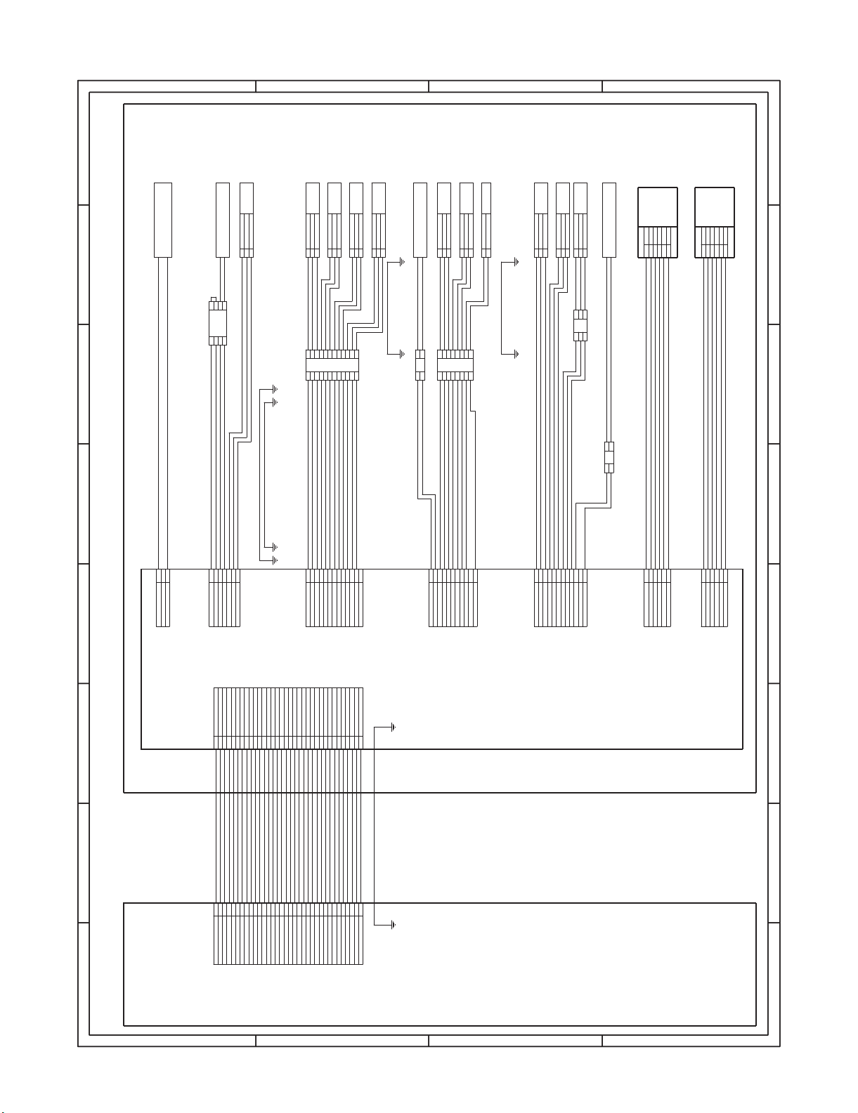
3. Actual wiring diagram
SPF paper feed reverse motor
SPRM
A
A
A
A
SPF transport motor
SPFM
+24V
B/
WH
YE
ORB/REA/BR
B
A
+24V
+24V
BL
YE
WH
21
21
21
21
3
3
3
3
B
B
B
SPF cover SW
SCOV
+24VPD
+24VPD_SW
1
2
B
SPF document width detection
SPWS
GND
SPWS
AVCC
BRGYBL
1
3
PHNR-03-H
22
1
3
BU03P-TR-P-H(LF)
PHNR-03-H
SPF paper feed clutch
SPFC
1
2
SMR-02V-B
2
1
SMP-02V-BC
A/
ORREBR A
+24VBLB
SPLS1
123
179228-3
SPF document length sensor
short
SPLS1
GND
+5VPD_LPLS1
SPLS2
179228-3
SPF document length sensor
long
SPLS2
GND
+5VPD_LPLS2
213
+5VPD
3
1
SPF paper entry detection 2
SPPD2
SPPD22
2549
C
C
C
C
SPF paper entry sensor 1
PS front
PF scan front detection S
SPPD3
GND
+5VPD
SPPD3
1
2
3
PHR-3
6
753
101112
8
7
6
GND
1
8
4
179228-3
101112
3
SPF open/close detection
SOCD
GND
SOCD
2
1
3 +5VPD_SOCD
291
BU12P-TR-P-H(LF)
PHR-3
+5VPD
3
SPF reverse rear detection
SPPD5
SPPD5
2
GND
1
SPF resist roller clutch
SRRC
2
PHNR-02-H
1
21
PHNR-2-H
SPF document empty detection
SPED
+5V_SPED3
SPED2GND
1
2
179228-3
1823
PHNR-08-H
6
7
BU02P-TR-P-H(LF)
PHNR-8-H
PHR-3
546
3 +5VPD
SPPD1
SPPD1
7
24315
Common with random detection
1 GND
8
PS-187-2V
BU08P-TR-P-H(LF)
D
D
D
D
1/1
12345678
12345678
12345678
12345678
Stamp solenoid
SPF reverse gate front
SPF document exit gate solenoid
SGS
179228-4
175694-4
179228-4
detection
GND
STMPS
+5VPD
SPPD4
3
1
2 SPPD4
PHR-3
1
4
3
STMPS/ 2
+24VPD_STMPS4
STMPU
GND1
2
3
PHR-3
PHNR-12-H
PHNR-12-H
1
B3B-PH-K-S
CN-C
+24VPD_SGS
RSPF
569
72834110
SPPD2
11
12
13
SPPD5
+5VPD
GND
GND
+5VPD_SOCD
SOCD
+5VPD
SPPD3
GND
GND
N.C.
B11B-PH-K-S
CN-E
1
SPED
GND
+24VPD_SRRC
SRRC/
569
+5V_SPED
+5VPD
72834
SPPD1
10
11
GND
+24VPD
GND
+24VPD_SW
1
SPLS1
B12B-PH-K-S
CN-D
+5VPD_LPLS1
SPLS2
GND
569
72834
+5VPD_SPLS2
AVCC
GND
SPWS
GND
101112
+24VPD_SW_SPFC
GND
SPFC/
1
+24VPD
SPRMA/
B6B-PH-K-R(RED)
CN-H
SPRMA
SPRMB
56234
+24VPD
SPRMB/
B6B-PH-K-S
CN-F
1
SPFMA/
253
+24VPD
SPFMA
4
SPFMB
+24VPD
6
SPFMB/
56723
4
B7B-PH-K-S
CN-B
1
GND
STMPU
SPPD4
+5VPD
+24VPD_STMPS
STMPS/
GND
CN-G
+5VPD
B13B-PH-K-S
3
2
SGS/
N.C
RSPF DRIVER PWB
+5V
GND
GND
+24VPD
+24VPD
SPPD2
CN-A
1
GND
CN-101
B34B-XADSS-F
2
GND
SPPD1
352641B34B-PHDSS-B
SPPD1
SPPD2
SPFMCK
AVCC
SPFMM1
SPFMM2
SPFMO1
SPFMO2
10
1191481825132316
610411735
9
13
+5V
+24V
+24V
SPFMCK
AVCC
SPFMM1
SPFMM2
SPFMO1
SPFMO2
SPRMA
142212
SPRMA
SPRMA/
15
SPRMA/
SPRMB
SPRMB
SPRMB/
17
172416
SPRMB/
SGS
SPRMO1
SGS
SPRMO1
STMPS
20
STMPS
SPWS
SELB
SPPD4
SRRC
SELC
SPFC
SELA
SPFFAN
SSELO
SPPD3
GND
GND
SPPD5
5VPD
26
221219
28724
2930313233
27
25192326201518
2730313233
SELB
SELC
SSELO
28829
SPPD4
SPFFAN
SPPD3
SPPD5
34
34
GND
GND
5VPD
87654
87654
87654
87654
21
21
SPWS
SRRC
SPFC
SELA
Scanner
D
D
D
D
B
B
B
C
C
C
C
B
MX-RPX1 ELECTRICAL SECTION 10 – 4
A
A
A
A
Page 33
[11] OTHERS
1. RSPF mixed-loaded document select switch
This machine is provided with the random paper feed function
which feeds mixed-loaded documents of different sizes.
Random paper feed can use only one side document of the following combination
Destination Random possible combination
AB series A3 and B4
B4 and A4R
A4 and B5
B5 and A5
Inch width 8.5" and 11" width
To use the mixed-loaded document mode, set the mixed-loaded
document select switch to ON.
Without the mixed-loaded document mode, set the mixed-loaded
document select switch to OFF.
Service Manual
OFF
ON
MX-RPX1 OTHERS 11 – 1
Page 34

Memo
Page 35

q
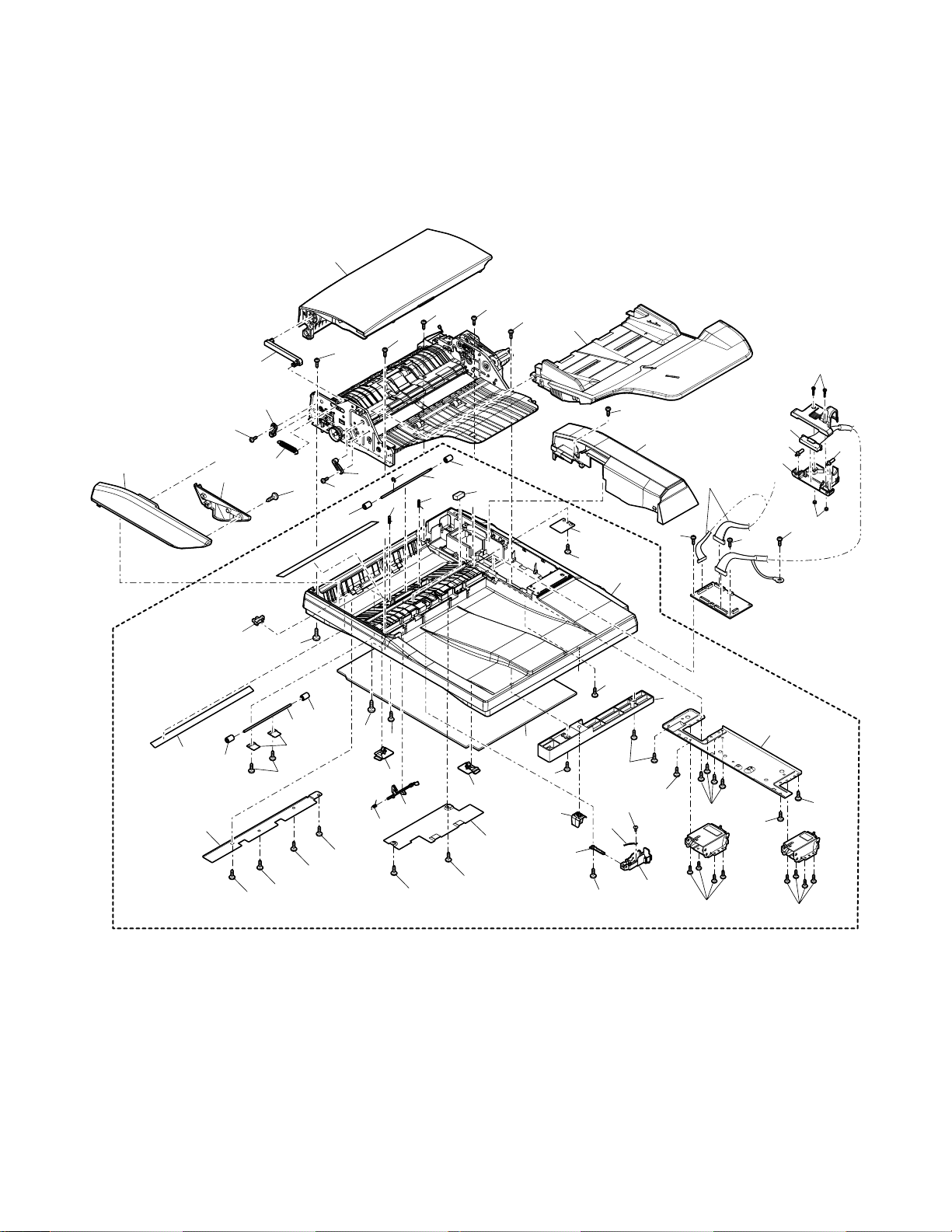
PARTS GUIDE
1
外装部 (Exteriors)
2
原稿トレイ (Original tray)
3
給紙部 (Paper feeding section)
4
分離部 (Separation section)
5
搬送部 1(Transport section 1)
6
搬送部 2(Transport section 2)
7
搬送部 3(Transport section 3)
MODEL
このパーツガイドに掲載されている表示価格ランクは消費税抜きです。
CONTENT
MX-RPX1
8
中間トレイ (Middle tray)
9
駆動ユニット (Drive unit)
F
梱包&付属品 (Packing material & Accessories)
G
RSPF ドライバー基板ユニット (RSPF driver PWB unit)
■ 索引 (Index)
SHARP CORPORATION
Page 36

補修部品のランク付
市場における補修部品の在庫管理が、適正に運営出来る手助けとなることを、目的とします。
Aランク : メンテナンスパーツ、メンテナンスパーツには入っていないがメンテナンスパーツに近い消耗パーツ。
Bランク : 性能・機能パーツ(センサー、クラッチ等の電気パーツ)、消耗パーツ。
Eランク : 基板含むユニットパーツ。
Dランク : 整備パーツ(外装、パッキング、同梱パーツ)。
Cランク : 上記ランク以外のパーツ(基板の子部品を除いたもの)。
DEFINITION
Rank A : Maintenance parts, and consumable parts which are not included in but closely related to maintenance parts
Rank B : Performance/function parts (sensors, clutches, and other electrical parts), consumable parts
Rank E : Unit parts including PWB
Rank D : Preparation parts (External fitting, packing, parts packed together)
Rank C : Parts other than the above (excluding sub components of PWB)
安全性・信頼性確保のため部品は、必ず正規のものをご使用下さい。
!
印の商品は、安全上重要な部品です。交換をする時は、安全及び性能維持のため必ず指定の部品をご使用下さい。
Because parts marked with "!" is indispensable for the machine safety maintenance and operation, it must be replaced with
the parts specific to the product specification.
F
当モデルのサービス資料には、この資料以外にサービスマニュアル ( 回路図含む ) があります。合わせてご利用下さい。
F Other than this Parts Guide, please refer to documents Service Manual(including Circuit Diagram)of this model.
F Please use the 13 digit code described in the right hand corner of front cover of the document, when you place an order.
F For U.S. only-Use order codes provided in advertising literature. Do not order from parts department.
1
外装部 (Exteriors)
NO. PARTS CODE
1 CGIDM2137DS51 BN LE N E
2 CSOU-0205DS51 BH GX N E
3 GCAB-1107FCZZ AS EZ N D
4 DHAI-3760FCZZ AN EQ N C
5 XEBS740P10000 AA DD C
6 PSHEZ5374FCZZ AD DJ N C
7 XHBS730P06000 AC DD C
8 XBBS730P16000 AA DD C
10 DHAI-3759FCZZ AU FG N C
11 LX-BZ1028FCZZ AC DD N C
12 PCOVP1930FCZZ AE DS N C
13 XNES730-24000 AA DD C
15 LSOU-0203FCZ1 BG GT N D
16 LPLTM6553FCZZ AM EG C
17 XEBS740P10000 AA DD C
20 PCOVP1824FCZZ AE DS N C
21 LX-BZ0531FCPZ AB DD C
22 DHAI-3761FCZZ AH DX N C
23 XEBS730P08000 AC DD C
24 LHLDZ1540FCZZ AG DS C
25 XEBS730P10000 AC DD C
26 PCOVP1855FCZZ AF DS N C
27 CCLEZ0020QS01 AK EB D
28 PHAG-0005FCZZ AC DJ N C
29 MLEVP0930FCZZ AC DJ N C
30 MSPRD3375FCZZ AB DJ C
31 PCOVP1856FCZ1 AE DS N C
32 LPLTM6554FCZZ AC DJ C
33 NSFTZ0009QSPZ AL EB C
34 NROLP1517FCZZ AA DJ N C
35 PSHEZ5372FCZZ AE DJ N C
36 VHPGP1A71L3-1 AG DS B
38 MSPRC3352FCZZ AB DJ C
39 PMLT-1418FCZZ AA DJ N C
40 XEBS730P08000 AC DD C
41 NSFTZ2914FCZZ AP EQ N C
42 XRESP30-06000 AA DD C
43 LHLDZ1640FCZZ AC DJ N C
44 LX-BZ0930FCPZ AC DD N C
45 GCAB-1106FCZZ AN EG N D
46 GCOV-0249FCZZ AF DS N D
47 MSPRT3390FCZZ AC DJ C
48 PSHEZ5400FCZ1 AX FG N D
49 XHBS740P08000 AA DD C
50 MARMP0325FCZZ AC DJ N C
51 PCOVP2017FCZZ AL EB N C
501 CSOU-0203DS51 BW RJ N E
PRICE RANK
Ex. Ja.
NEW
MARK
PART
RANK
Paper feeding roller unit 給紙ローラーユニット
Original tray unit 原稿トレイユニット
RSPF rear cabinet RSPF 後キャビネット
Transport interface main harness 搬送中継メインハーネス
Screw(4×10) ビス
OC positioning sheet OC 位置決めシート
Screw(3×6) ビス
Screw(3×16) ビス
RSPF connection harness RSPF 接続ハーネス
Screw ELCON 段ビス
Harness cover lower ハーネスカバー下
Nut(M3) 六角ナット
RSPF base tray RSPF ベーストレイ
Hinge fixing plate ヒンジ取付板
Screw(4×10) ビス
Stamp cover スタンプカバー
Screw(4×8) ビス
Base tray harness ベーストレイハーネス
Screw(3×8) ビス
Fulcrum holder 支点ホルダー
Screw(3×10) ビス
Sensor cover センサーカバー
SPF glass cleaner AS SPF ガラスクリーナー AS
OC mat fixing hook OC マット取付フック
Paper exit actuator 出紙アクチュエーター
Paper exit return spring 出紙復帰スプリング
Follower roller cover 従動ローラーカバー
Follower roller fixing plate 従動ローラー押え板
Transport follower shaft 搬送従動軸
Delivery follower roller RSPF 排紙従動ローラー RSPF
Reading front sheet 読取前シート
Photo sensor(GP1A71L3) フォトセンサー
Follower pressure spring 従動加圧スプリング
Gate stopper cushion ゲートストッパーモルト
Screw(3×8) ビス
Follower roller shaft 従動ローラー軸
E-ring(E3) E リング
Paper feeding PG holder 給紙 PG ホルダー
Screw(4×6) ビス
RSPF front cabinet RSPF 前キャビネット
F cabinet cover F キャビネットカバー
Link arm return spring リンクアーム復帰スプリング
OC mat OC マット
Screw(4×8) ビス
Upper PG link arm 上 PG リンクアーム
Base lower right cover ベース右下カバー
Base tray unit(Without No.5,7,27,40,48) ベーストレイユニット
DESCRIPTION
(No.5,7,27,40,48 除く )
– 1 –
Page 37
1
外装部 (Exteriors)
1
45
501
35
31
46
34
49
36
17
50
43
47
23
17
33
32
17
34
28
39
26
5
7
2
8
49
10
48
17
27
24
6
21
25
22
3
4
5
15
5
17
23
51
7
17
20
17
11
12
7
16
17
7
17
11
13
17
5
43
5
30
38
40
28
5
29
42
17
41
38
5
44
5
34
5
34
17
17
FCP08991
– 2 –
Page 38

2
原稿トレイ (Original tray)
NO. PARTS CODE
1 LPLTP6485FCZZ AG DX N C
2 LPLTP6486FCZZ AG DX N C
3 DHAI-3764FCZZ AK DX N C
4 TLABZ5063FCZZ AP EQ N D
5 LSOU-0204FCZZ AV FG N D
6 LSOU-0205FCZZ AU EZ N D
7 XEBS740P10000 AA DD C
8 NROLP1517FCZZ AA DJ N C
9 NSFTZ2914FCZZ AP EQ N C
10 XRESP30-06000 AA DD C
11 MSPRC3352FCZZ AB DJ C
12 CPWBF1594FCE2 AS EQ E
13 XEBS730P08000 AC DD C
14 LPLTP0321QSZZ AE DS C
15 NGERP0168QSZZ AD DJ C
16 VHPGP1S73P+-1 AF DS B
17 XEPS730P08X00 AA DD C
18 NGERR0169QSZZ AE DS C
19 MSPRP0315QSZZ AD DJ C
20 MLEVP0098QSZZ AC DJ C
3
給紙部 (Paper feeding section)
NO. PARTS CODE
1 PCOVP1851FCZZ AT EZ N C
2 QSW-M0502FCPZ AH DX N B
3 DHAI-3763FCZZ AH DX N C
4 PGIDM2137FCZZ AV FG N C
5 NSFTZ2913FCZZ AX FQ N C
6 LPINS0089FCZZ AA DD C
7 XRESP50-06000 AA DD C
8 XPSSP20-10000 AA DD N C
9 NBRGM0096FCZ1 AC DJ C
10 NGERH0863FCBZ AD DJ C
11 MARMP0324FCZZ AB DJ N C
12 MARMP0339FCZZ AC DJ N C
13 MARMP0330FCZZ AC DJ N C
14 PGIDM2138FCZZ AD DJ N C
16 XRESP40-06000 AA DD C
17 LHLDR1650FCZZ AD DJ N C
18 NSFTZ2915FCZZ AM EG N C
19 NPLYZ0452FCZZ AC DJ N C
20 NBLTH0442FCZZ AD DJ B
21 NROLR1542FCZZ AH DX N B
22 PGIDM2139FCZZ AC DJ N C
23 NROLR1541FCZZ AG DX N B
24 NCPL-0049FCZZ AH DX B
25 NPLYZ0437FCZZ AT EZ C
26 LX-WZ0443FCPZ AB DD C
28 XEBS740P10000 AA DD C
29 PSHEP5442FCZZ AC DJ N C
30 PMLT-1417FCZZ AC DJ N C
31 MSPRD3378FCZZ AB DJ C
32 MLEVP0932FCZZ AC DJ N C
33 MLEVP0953FCZZ AC DJ C
34 VHPGP1S73P+-1 AF DS B
35 VHPGP1A71L3-1 AG DS B
36 NSFTZ0009QSPZ AL EB C
37 NROLP1517FCZZ AA DJ N C
38 LHLDZ1755FCZZ AC DJ N C
39 MSPRC3571FCZZ AB DJ N C
41 XWHS730-05080 AA DD C
42 XEBS730P16000 AA DD C
43 PSHEP5466FCZZ AA DJ N C
44 MLEVP1034FCZZ AC DJ N C
46 XEPS730P08X00 AA DD C
PRICE RANK
Ex. Ja.
PRICE RANK
Ex. Ja.
NEW
MARK
NEW
MARK
PART
RANK
RSPF regulation plate F RSPF 規制板 F
RSPF regulation plate R RSPF 規制板 R
Original tray harness 原稿トレイハーネス
Original size label (Except Japan) 原稿サイズラベル
RSPF original tray upper RSPF 原稿トレイ上
RSPF original tray lower RSPF 原稿トレイ下
Screw(4×10) ビス
Delivery follower roller RSPF 排紙従動ローラー RSPF
Follower roller shaft 従動ローラー軸
E-ring(E3) E リング
Follower pressure spring 従動加圧スプリング
SPF VR PWB LF SPF VR 基板 LF
Screw(3×8) ビス
Width detection fixing plate TLPD 幅検知取付板 TLPD
Width detection gear(36T) 幅検知ピニオン
Photo sensor(GP1S73P) フォトセンサー
Screw(3×8X) ビス
Width detection rack gear 幅検知ラック TLP
Regulation plate spring TLPD 規制板スプリング TLPD
Original detect actuator 原稿検知アクチュエーター
PART
RANK
Upper cover 上カバー
Interlock switch(51632C531N) インターロックスイッチ
Paper feeding roller harness 給紙ローラーハーネス
Paper feeding transport upper guide 給紙搬送上ガイド
Paper feeding shaft 給紙軸
Spring pin スプリングピン
E-ring(E5) E リング
Spring pin(φ2-10) スプリングピン
Bearing 軸受
Pick up gear(18T) ピックアップギヤ
Lock arm ロックアーム
Lock release arm ロック解除アーム
Paper lock arm 紙ロックアーム
Upper transport auxiliary guide 上搬送補助ガイド
E-ring(E4) E リング
Pick up roller holder ピックアップローラーホルダー
Pick up shaft ピックアップ軸
Pick up pulley(18P) ピックアッププーリー
Belt(132) ベルト
Pick up roller ピックアップローラー
Holder guide ホルダーガイド
Paper feeding separation roller 給紙分離ローラー
Oneway coupling ワンウェイカップリング
Paper feeding pulley RSPF(18P) 給紙プーリー RSPF
Washer ワッシャー
Screw(4×10) ビス
PS front sheet PS 前シート
Pick up silence cushion ピックアップ消音モルト
Detection return spring 入紙検知復帰スプリング
Detection actuator 入紙検知アクチュエーター
PE actuator PE アクチュエーター
Photo sensor(GP1S73P) フォトセンサー
Photo sensor(GP1A71L3) フォトセンサー
Transport follower shaft 搬送従動軸
Delivery follower roller RSPF 排紙従動ローラー RSPF
PS pressure welding holder PS 圧接ホルダー
PS pressure welding spring PS 圧接スプリング
Washer(φ3-8t0.5) ワッシャー
Screw(3×16) ビス
PS rear sheet PS 後シート
Change lever 切替レバー
Screw(3×8X) ビス
DESCRIPTION
DESCRIPTION
– 3 –
Page 39
2
原稿トレイ (Original tray)
2
1
18
3
給紙部 (Paper feeding section)
19
17
13
12
18
17
15
14
13
16
3
20
16
7
4
5
20
11
10
11
9
8
6
7
8
7
FCP08992
42
41
42
38
39
41
37
38
31
39
32
23
28
22
36
24
1
8
7
10
9
25
29
35
26
6
43
28
43
26
3
5
4
11
14
12
13
12
11
13
33
2
34
46
44
29
28
29
43
28
9
7
19
20
21
28
30
16
17
18
FCP08993
– 4 –
Page 40

4
分離部 (Separation section)
NO. PARTS CODE
1 PCOVP1850FCZZ AD DJ N C
3 XHBS740P08000 AA DD C
4 PCLR-0461FCZZ AC DJ C
5 PGIDM2136FCZZ AL EB N C
6 NSFTZ0009QSPZ AL EB C
7 NROLP1517FCZZ AA DJ N C
8 PSHEZ3130FCZZ AB DD C
9 MSPRC3355FCZZ AB DJ C
10 NROLR1555FCZZ AG DX N B
12 LPINS0089FCZZ AA DD C
13 XRESP50-06000 AA DD C
14 NSFTZ2912FCZZ AX FG N C
15 LHLDZ1670FCZZ AC DJ C
16 MSPRT3391FCZZ AB DJ C
17 XEBS740P10000 AA DD C
18 LPLTM6557FCZZ AH DX N C
21 PGIDM2135FCZZ AN EG N C
23 NBRGP0668FCZZ AE DJ C
24 XRESP40-06000 AA DD C
26 XEBS730P08000 AC DD C
(Unit)
901 CGIDM2136DS51 BF GN N E
4
分離部 (Separation section)
PRICE RANK
Ex. Ja.
NEW
MARK
PART
RANK
Separation roller cover 分離ローラーカバー
Screw(4×8) ビス
U-turn collar U ターンコロ
Separation transport guide 分離搬送ガイド
Transport follower shaft 搬送従動軸
Delivery follower roller RSPF 排紙従動ローラー RSPF
Rotation plate sheet 回転板シート
Roller spring 圧縮従動ローラースプリング
Separation roller 分離ローラー
Spring pin スプリングピン
E-ring(E5) E リング
Separation shaft 分離軸
Separation roller fulcrum holder 分離ローラー支点ホルダー
SPF pressure spring SPF 圧接スプリング
Screw(4×10) ビス
Separation PG reinforce plate 分離 PG 補強板
Middle guide 中間ガイド
Stopper bearing ストッパー軸受
E-ring(E4) E リング
Screw(3×8) ビス
Separation roller guide unit 分離ローラーガイドユニット
DESCRIPTION
901
1
7
3
3
4
3
4
5
6
26
24
23
15
8
13
12
14
16
17
18
9
9
10
17
7
17
26
– 5 –
21
FCP08994
Page 41

5
搬送部 1(Transport section 1)
NO. PARTS CODE
1 NBRGM0501FCZZ AB DJ C
2 MSPRC3357FCZZ AA DJ C
3 XWHS760-08115 AA DD N C
4 PRNGP0090FCZZ AA DJ C
5 PCLC-0337FCZZ BA FX N B
6 XRESP40-06000 AA DD C
7 NGERH1681FCZZ AC DJ N C
8 XRESP30-04000 AA DD C
9 NGERH1682FCZZ AT EZ C
10 XRESP50-06000 AA DD C
11 NPLYZ0454FCZZ AC DJ C
12 NBLTH0444FCZZ AS EQ N B
13 PSHEZ5377FCZZ AA DJ N C
15 XPSSP20-10000 AA DD N C
17 NPLYZ0453FCZZ AC DJ N C
19 NROLR1545FCZ1 BD GJ N B
20 NROLR1552FCZZ AX FG N B
21 NROLR1543FCZZ AU EZ N B
22 CFRM-1167FC01 AL EB N C
23 CFRM-1183FC01 AR EQ C
24 LX-WZ5002BCZZ AA DD C
5
搬送部 1(Transport section 1)
PRICE RANK
Ex. Ja.
NEW
MARK
PART
RANK
Metal bearing メタル軸受
Brake spring ブレーキスプリング
Washer ワッシャー
E-ring(E5) 樹脂 E リング
SP clutch SPF PS クラッチ SPF
E-ring(E4) E リング
Gear(36T) ギヤ
E-ring(E3) E リング
Oneway gear(32T) ワンウェイギヤ
E-ring(E5) E リング
Gear pulley(25/24) ギヤプーリー
Belt(200) ベルト
Pulley sheet(25) プーリーマイラー
Spring pin(φ2-10) スプリングピン
Drive pulley(24P) 駆動プーリー
Delivery roller 排紙ローラー
Reading front roller 読取前ローラー
PS roller PS ローラー
Frame F AS フレーム F AS
Frame R AS フレーム R AS
Washer ポリスライダー
DESCRIPTION
10
24
1
10
24
22
5
4
3
2
1
8
7
6
8
11
13
10
24
23
9
1
17
15
1
12
21
20
19
1
10
1
FCP08995
– 6 –
Page 42

6
搬送部 2(Transport section 2)
NO. PARTS CODE
1 NROLR1535FCZZ AT EZ N B
2 XEBS740P10000 AA DD C
3 PGIDM2130FCZZ AV FG N C
4 CFRM-1183FC01 AR EQ C
6 NGERH1680FCZZ AC DJ N C
7 XRESP30-04000 AA DD C
8 XHBS740P08000 AA DD C
10 XRESP50-06000 AA DD C
12 NGERH1646FCZZ AC DJ N C
13 NBRGP0041GCZZ AD DJ C
14 PRNGP0090FCZZ AA DJ C
15 NGERH1620FCZZ AC DJ C
16 XPSSP20-10000 AA DD N C
17 NBRGM0501FCZZ AB DJ C
18 PGIDM2150FCZZ AE DJ N C
19 MSPRD3380FCZ1 AB DJ N C
20 MLEVP0963FCZZ AC DJ N C
21 CSOU-0206DS51 BA FX N D
22 PGIDM2152FCZZ AL EB N C
23 PSHEZ5375FCZZ AD DJ N C
24 PGIDM2134FCZZ AN EG N C
25 MLEVP0974FCZZ AD DJ N C
26 MSPRD3377FCZZ AB DJ C
27 MSPRC3353FCZZ AB DJ C
28 VHPGP1A71L3-1 AG DS B
29 LPLTM6556FCZZ AC DJ C
31 NBRGM0501FCZZ AB DJ C
32 CFRM-1167FC01 AL EB N C
34 DHAI-3762FCZZ AK DX N C
35 MSPRD3376FCZZ AB DJ C
36 MLEVP0931FCZZ AC DJ N C
37 MLEVP0930FCZZ AC DJ N C
38 MSPRD3375FCZZ AB DJ C
39 XRESP50-06000 AA DD C
40 PMLT-1418FCZZ AA DJ N C
41 PCOVP2018FCZZ AC DJ N C
42 PCOVP2019FCZZ AC DJ N C
43 PSHEP5461FCZZ AA DJ N C
501 DUNT-7479DSZZ BG GT N E
PRICE RANK
Ex. Ja.
NEW
MARK
PART
RANK
SWB transport roller SWB 搬送ローラー
Screw(4×10) ビス
Transport guide 搬送ガイド
Frame R AS フレーム R AS
Gear(20T) ギヤ
E-ring(E3) E リング
Screw(4×8) ビス
E-ring(E5) E リング
Gear(25T) ギヤ
Bearing 軸受
E-ring(E5) 樹脂 E リング
Gear(32T) ギヤ
Spring pin(φ2-10) スプリングピン
Metal bearing メタル軸受
Reversal rear guide 反転後ガイド
Gate spring ゲートスプリング
Reversal gate link lever 1 反転ゲートリンクレバー 1
Middle tray unit 中間トレイユニット
Reversal guide 反転ガイド
Reading rear PG sheet 読取後 PG シート
Delivery upper guide 排紙上ガイド
Reversal rear actuator 反転後アクチュエーター
Reversal rear spring 反転後スプリング
Reading plate spring 読取板圧接スプリング
Photo sensor(GP1A71L3) フォトセンサー
Paper feeding sensor fixing plate 給紙センサー取付板
Metal bearing メタル軸受
Frame F AS フレーム F AS
Transport harness 搬送ハーネス
Reading front spring 読取前スプリング
Reading front actuator 読取前アクチュエーター
Paper exit actuator 出紙アクチュエーター
Paper exit return spring 出紙復帰スプリング
E-ring(E5) E リング
Gate stopper cushion ゲートストッパーモルト
PS shaft cover F PS 軸カバー F
PS shaft cover R PS 軸カバー R
PS guide sheet PS ガイドマイラー
Transport paper guide unit 搬送ペーパーガイドユニット
DESCRIPTION
7
搬送部 3(Transport section 3)
NO. PARTS CODE
1 NROLR1540FCZZ AV FG N B
2 LPINS0089FCZZ AA DD C
3 LPLTM6555FCZ1 AN EG N C
4 MSPRC3453FCZZ AB DJ C
5 LHLDZ1649FCZZ AD DJ C
6 NBRGC0017QSZZ AC DJ C
7 NPLYZ0451FCZZ AC DJ C
8 XRESP50-06000 AA DD C
9 PCLR-0520FCZZ AB DJ N C
10 LX-BZ0833FCPZ AC DD C
11 LHLDZ1641FCZZ AC DJ N C
12 MSPRT3392FCZZ AB DJ C
13 CFRM-1183FC01 AR EQ C
14 XRESP30-04000 AA DD C
15 NPLYZ0434FCZZ AC DJ N C
16 NGERH1646FCZZ AC DJ N C
17 XPSSP20-10000 AA DD N C
18 NPLYZ0456FCZZ AT EZ C
19 NBLTH0435FCZZ AS EQ N B
20 PSHEZ5377FCZZ AA DJ N C
21 NBRGM0096FCZ1 AC DJ C
22 PSHEZ5394FCZZ AA DJ N C
23 XHBS730P08000 AB DD C
24 LPLTM6492FCZZ AC DJ C
25 RPLU-0366FCZZ AQ EQ N B
26 XBBS730P04000 AA DD C
27 NBLTH0438FCZZ AS EQ N B
29 NBRGM0501FCZZ AB DJ C
30 XWHS730-05080 AA DD C
32 LHLDZ1651FCZZ AC DJ N C
34 MSPRC3356FCZZ AA DJ C
35 PTME-0030QSZZ AC DJ C
36 PSHEP5422FCZZ AH DX N C
37 NROLR1544FCZZ AY FQ N B
38 CFRM-1167FC01 AL EB N C
40 NBLTH0441FCZZ AD DJ B
PRICE RANK
Ex. Ja.
NEW
MARK
PART
RANK
Roller プラテンローラー
Spring pin スプリングピン
Reading plate 読取板
Reading plate rotation spring 読取板回転スプリング
Reading plate holder R 読取板ホルダー R
Bearing 軸受
Pulley(20P) プーリー
E-ring(E5) E リング
Tension collar テンションコロ
Screw 回転板用段ビス
Tension holder A テンションホルダー A
Tension spring テンションスプリング
Frame R AS フレーム R AS
E-ring(E3) E リング
Gear pulley(32/25) ギヤプーリー
Gear(25T) ギヤ
Spring pin(φ2-10) スプリングピン
JAM release pulley JAM 解除プーリー
Belt(188) ベルト
Pulley sheet(25) プーリーマイラー
Bearing 軸受
Pulley sheet(25R) プーリーマイラー
Screw(3×8) ビス
Solenoid adjustment plate ソレノイド調整板
Gate solenoid ゲートソレノイド
Screw(3×4) ビス
Belt(190) ベルト
Metal bearing メタル軸受
Washer(φ3-8t0.5) ワッシャー
Stopper holder ストッパホルダー
Lock spring ロックスプリング
Open/shut lock pawl TLP 開閉ロック爪 TLP
White sheet 白マイラー
Reading rear roller 読取後ローラー
Frame F AS フレーム F AS
Belt(116) ベルト
DESCRIPTION
– 7 –
Page 43

6
7
搬送部 3(Transport section 3)
NO. PARTS CODE
41 NPLYZ0029QSZZ AD DJ C
42 JKNBZ0149FCZZ AC DJ N C
43 PRNGP0090FCZZ AA DJ C
44 MLEVP0972FCZZ AB DJ N C
45 MSPRC0153QSZZ AB DJ C
46 VHPGP1S73P+-1 AF DS B
47 XHBS740P08000 AA DD C
48 LPLTP0131QSZZ AD DJ C
49 LHLDZ1648FCZZ AD DJ C
50 DHAI-3837FCZZ AC DJ N C
51 LHLDW1491FCZZ AG DS C
52 XHBS730P06000 AC DD C
搬送部 2(Transport section 2)
PRICE RANK
Ex. Ja.
43
NEW
MARK
41
501
36
35
34
37
PART
RANK
Delivery drive pulley(34T) 排紙駆動プーリー
JAM release knob P JAM 解除ノブ P
E-ring(E5) 樹脂 E リング
Book sensor actuator ブックセンサーアクチュエーター
Book sensor spring ブックセンサースプリング
Photo sensor(GP1S73P) フォトセンサー
Screw(4×8) ビス
Book sensor fixing plate ブックセンサー取付板
Reading plate holder F 読取板ホルダー F
Reading plate earth harness 読取板アースハーネス
Wire holder(MWSEB-2-01A_RT) ワイヤーサドル
Screw(3×6) ビス
43
42
43
31
39
38
2
1
2
3
DESCRIPTION
28
6
4
2
27
16
10
17
8
15
14
2
13
16
17
12
7
32
2
8
2
13
14
2
FCP08996
7
搬送部 3(Transport section 3)
49
6
8
4
47
48
46
44
45
43
23
42
41
40
27
29
29
40
13
18
19
20
21
30
9
11
12
20
27
7
19
10
23
29
23
15
8
26
22
18
14
17
16
23
25
24
26
28
24
2
23
40
52
2
1
3
34
32
23
8
21
38
51
5
4
23
36
35
37
6
35
22
32
34
25
50
8
7
2
8
21
FCP08997
– 8 –
Page 44

8
中間トレイ (Middle tray)
NO. PARTS CODE
1 LSOU-0206FCZZ AR EQ N D
2 MSPRC3358FCZZ AA DJ C
3 NROLP1517FCZZ AA DJ N C
4 NSFTZ0009QSPZ AL EB C
5 NROLR1590FCZZ AT EZ N B
6 NBRGM0501FCZZ AB DJ C
7 XRESP50-06000 AA DD C
8 PBRSS0230FCZZ AE DS N B
9 PGIDH2153FCZZ AG DX N C
10 XEBS740P10000 AA DD C
11 PSHEZ5449FCZZ AC DJ N C
8
中間トレイ (Middle tray)
PRICE RANK
Ex. Ja.
NEW
MARK
PART
RANK
RSPF middle tray RSPF 中間トレイ
RSPF delivery follower spring RSPF 排紙従動スプリング
Delivery follower roller RSPF 排紙従動ローラー RSPF
Transport follower shaft 搬送従動軸
SWB roller SWB ローラー
Metal bearing メタル軸受
E-ring(E5) E リング
Discharge brush RSP 除電ブラシ RSP
Middle tray guide 中間トレイガイド
Screw(4×10) ビス
Delivery sheet RSPF(38) 排紙シート RSPF
DESCRIPTION
10
11
1
2
2
3
4
3
9
5
10
11
8
6
7
8
FCP08998
– 9 –
Page 45

9
駆動ユニット (Drive unit)
NO. PARTS CODE
1 NPLYZ0435FCZZ AC DJ C
2 PSHEP5441FCZZ AB DJ N C
4 QEARP0218FCPZ AE DS N C
6 LSTPP0016QSZZ AC DJ C
7 PCLC-0017QSPZ AT EQ N B
8 NPLYZ0033QSZZ AD DJ C
9 NBLTH0443FCZZ AE DJ B
10 NSFTZ2916FCZZ AS EQ N C
11 XPSSP20-10000 AA DD N C
12 NBRGM0096FCZ1 AC DJ C
13 XHBS740P06000 AA DD C
14 CPLTM6558FC01 AN EQ C
15 NGERH1619FCZZ AC DJ N C
16 NBLTH0437FCZZ AS EQ N B
17 NPLYZ0446FCZZ AC DJ N C
20 PRNGP0090FCZZ AA DJ C
21 XRESP50-06000 AA DD C
22 NBLTH0436FCZZ AD DJ B
23 XBBS730P04000 AA DD C
24 PCLR-0520FCZZ AB DJ N C
25 XHBS730P08000 AB DD C
26 LX-BZ0833FCPZ AC DD C
27 LHLDZ1641FCZZ AC DJ N C
28 MSPRT3392FCZZ AB DJ C
29 XHBS730P08000 AB DD C
30 NGERH1621FCZZ AC DJ C
31 XWHS730-05080 AA DD C
32 NSFTZ2917FCZZ AM EG N C
33 NBRGM0096FCZ1 AC DJ C
34 MSPRT3570FCZZ AC DJ N C
(Unit)
901 DUNT-7478DSZZ BB FX N E
PRICE RANK
Ex. Ja.
NEW
MARK
PART
RANK
Pulley(38P) プーリー
Pulley sheet(38) プーリーマイラー
Motor earth tape lower モーターアーステープ下
Stopper(E5) ストッパー
SPF paper feeding clutch SPF 給紙クラッチ
Coupling pulley(39P) カップリングプーリー
Belt(250) ベルト
Paper feeding drive shaft 給紙駆動軸
Spring pin(φ2-10) スプリングピン
Bearing 軸受
Screw(4×6) ビス
Drive motor fixing plate AS 駆動モーター取付板 AS
Paper feeding drive gear(41T) 給紙駆動ギヤ
Belt(204) ベルト
Gear pulley(48/26) ギヤプーリー
E-ring(E5) 樹脂 E リング
E-ring(E5) E リング
Belt(176DSPF) ベルト
Screw(3×4) ビス
Tension collar テンションコロ
Screw(3×8) ビス
Screw 回転板用段ビス
Tension holder A テンションホルダー A
Tension spring テンションスプリング
Screw(3×8) ビス
Gear(23T) ギヤ
Washer(φ3-8t0.5) ワッシャー
Paper feeding follower shaft 給紙従動軸
Bearing 軸受
Paper feeding tension spring 給紙テンションスプリング
Drive fixing plate unit 駆動取付板ユニット
DESCRIPTION
9
駆動ユニット (Drive unit)
901
26
25
31
24
33
27
29
28
21
30
17
23
32
21
22
29
21
23
17
12
23
11
16
1
2
4
13
26
27
34
14
31
24
25
10
9
6
7
8
11
12
15
13
20
13
33
FCP08999
– 10 –
Page 46

F
梱包&付属品 (Packing material & Accessories)
NO. PARTS CODE
1 SPAKA6611FCZZ AF DS D
3 0EUSAK0608K// AC DJ D
4 SPAKA6793FCZZ AX FG N D
5 SSAKZ0002QSZZ AF DS D
6 SPAKA6794FCZZ AU EZ N D
7 SPAKC6792DSZZ BB GD N D
8 LX-BZ0776FCPZ AG DD N C
9 LX-BZ1024FCZZ AG DX N C
10 XBTSC50P16000 AA DD C
11 0EUSAK0617P// AB DJ D
F
梱包&付属品 (Packing material & Accessories)
PRICE RANK
Ex. Ja.
NEW
MARK
PART
RANK
DESCRIPTION
Packing add(390mm×440mm) エサフォーム
Vinyl bag(90mm×600mm) ポリ袋
Packing add top アド上
Vinyl bag(940mm×790mm) ポリ袋
Packing add bottom アド下
Packing case 個装ケース
Screw 段ビス R
Screw SPF 段ビス R
Screw(5×16) ビス
Vinyl bag(90mm×170mm) ポリ袋
1
10
4
3
4
11
5
6
6
9
8
7
FCP09000
– 11 –
Page 47

G
RSPF ドライバー基板ユニット (RSPF driver PWB unit)
NO. PARTS CODE
1 QCNCM0923FC3D AF DS C
2 QCNCM2401SC0F AB DJ C
3 QCNCM7014SC0C AA DD C
4 QCNCM7014SC0F AB DD C
5 QCNCM7014SC0G AB DD C
6 QCNCM7014SC1A AC DJ C
7 QCNCM7014SC1B AD DJ C
8 QCNCM7014SC1C AC DD C
9 VCEAGU1VW476M AB DD C
10 VCEAJA1CW476M AB DD C
11 VCKYCY1HB223K AC DD C
12 VCKYCZ1CF104Z AB DD C
13 VCKYCZ1CF473Z AA DD C
14 VCKYCZ1HB222K AA DD C
15 VHDDAN202K/-1 AB DD B
16 VHDDAP202K/-1 AB DD B
17 VHDDSS133//-1 AA DD B
18 VHEMTZJ20B/-1 AB DD B
21 VHITD62003AP1 AG DX B
22 VHI74HC151M-1 AD DJ B
23 VHVICPN15//-1 AD DJ B
24 VHVICPN20//-1 AD DS B
25 VRD-HT2EY221J AA DD C
VRS-CZ1JD101J AA DD C
26
VRS-CZ1JD101J AA DD C
VRS-CZ1JD103J AA DD C
27
VRS-CZ1JD103J AA DD C
28 VRS-CZ1JD391F AA DD C
30 VRS-CZ1JD472F AA DD C
31 VRS-CZ1JD473J AA DD C
32 VRS-CZ1JD511F AA DD C
33 VRS-CZ1JD511J AA DD C
34 VRS-RE3DAR47J AC DD C
36 VS2SK3065++-1 AG DX B
PRICE RANK
Ex. Ja.
NEW
MARK
PART
RANK
Connector(34pin) [CNA] コネクター
Connector(6pin) [CNH] コネクター
Connector(3pin) [CNC] コネクター
Connector(6pin) [CNF] コネクター
Connector(7pin) [CNB] コネクター
Connector(11pin) [CNE] コネクター
Connector(12pin) [CND] コネクター
Connector(13pin) [CNG] コネクター
Capacitor(35WV 47µF) [C10,16,33] コンデンサー
Capacitor(16WV 47µF) [C13,22,28] コンデンサー
Capacitor(50WV 0.022µF) [C12,17,34] コンデンサー
Capacitor(16WV 0.1µF) [C7,14,20,25,31] コンデンサー
Capacitor(16WV 0.047µF) [C11,15] コンデンサー
Capacitor(50WV 2200pF) [C3,4,5,6,29,30] コンデンサー
Diode(DAN202K) [D13,15,16] ダイオード
Diode(DAP202K) [D11,12,14] ダイオード
Diode(1SS133) [D5,6,18] ダイオード
Zener diode(MTZJ20BT-77) [ZD1] ツェナーダイオード
IC(TD620003AP1) [IC1] IC
IC(74HC151M) [IC4] IC
IC protector(ICP-N15) [ICP1,2,4] IC プロテクター
IC protector(ICP-N20) [ICP6] IC プロテクター
Resistor(1/4W 220Ω ±5%) [R5,10,13,18] テイコウ
Resistor(1/16W 100Ω ±5%) [R1,4,7,9,30,32,34,36,39] テイコウ
Resistor(1/16W 100Ω ±5%) [R41,42,47,48] テイコウ
Resistor(1/16W 10KΩ ±5%) [R2,3,6,8,11,26,27,28,45] テイコウ
Resistor(1/16W 10KΩ ±5%) [R46,51] テイコウ
Resistor(1/16W 390Ω ±1%) [R22,23] テイコウ
Resistor(1/16W 4.7KΩ ±1%) [R20,24] テイコウ
Resistor(1/16W 47KΩ ±5%) [R40,43,44] テイコウ
Resistor(1/16W 510Ω ±1%) [R21] テイコウ
Resistor(1/16W 510Ω ±5%) [R49,50] テイコウ
Resistor(2W 0.47Ω ±5%) [R15,17,29,38] テイコウ
Transistor(2SK3065) [Q5] トランジスター
DESCRIPTION
– 12 –
Page 48

■
索引 (Index)
PARTS CODE NO.
[C]
CCLEZ0020QS01
CFRM-1167FC01
CFRM-1183FC01
CGIDM2136DS51
CGIDM2137DS51
CPLTM6558FC01
CPWBF1594FCE2
CSOU-0203DS51
CSOU-0205DS51
CSOU-0206DS51
DHAI-3759FCZZ
DHAI-3760FCZZ
DHAI-3761FCZZ
DHAI-3762FCZZ
DHAI-3763FCZZ
DHAI-3764FCZZ
DHAI-3837FCZZ
DUNT-7478DSZZ
DUNT-7479DSZZ
GCAB-1106FCZZ
GCAB-1107FCZZ
GCOV-0249FCZZ
JKNBZ0149FCZZ
LHLDR1650FCZZ
LHLDW1491FCZZ
LHLDZ1540FCZZ
LHLDZ1640FCZZ
LHLDZ1641FCZZ
LHLDZ1648FCZZ
LHLDZ1649FCZZ
LHLDZ1651FCZZ
LHLDZ1670FCZZ
LHLDZ1755FCZZ
LPINS0089FCZZ
LPLTM6492FCZZ
LPLTM6553FCZZ
LPLTM6554FCZZ
LPLTM6555FCZ1
LPLTM6556FCZZ
LPLTM6557FCZZ
LPLTP0131QSZZ
LPLTP0321QSZZ
LPLTP6485FCZZ
LPLTP6486FCZZ
LSOU-0203FCZ1
LSOU-0204FCZZ
LSOU-0205FCZZ
LSOU-0206FCZZ
LSTPP0016QSZZ
LX-BZ0531FCPZ
LX-BZ0776FCPZ
LX-BZ0833FCPZ
LX-BZ0930FCPZ
LX-BZ1024FCZZ
LX-BZ1028FCZZ
LX-WZ0443FCPZ
LX-WZ5002BCZZ
MARMP0324FCZZ
MARMP0325FCZZ
MARMP0330FCZZ
MARMP0339FCZZ
MLEVP0098QSZZ
MLEVP0930FCZZ
MLEVP0931FCZZ
"
"
"
"
[D]
[G]
[J]
[L]
"
"
"
"
[M]
"
PRICE R.
Ex. Ja.
1- 27 AK EB D
5- 22 AL EB N C
6- 32 AL EB N C
7- 38 AL EB N C
5- 23 AR EQ C
6- 4 AR EQ C
7- 13 AR EQ C
4- 901 BF GN N E
1- 1 BN LE N E
9- 14 AN EQ C
2- 12 AS EQ E
1- 501 BW RJ N E
1- 2 BH GX N E
6- 21 BA FX N D
1- 10 AU FG N C
1- 4 AN EQ N C
1- 22 AH DX N C
6- 34 AK DX N C
3- 3 AH DX N C
2- 3 AK DX N C
7- 50 AC DJ N C
9- 901 BB FX N E
6- 501 BG GT N E
1- 45 AN EG N D
1- 3 AS EZ N D
1- 46 AF DS N D
7- 42 AC DJ N C
3- 17 AD DJ N C
7- 51 AG DS C
1- 24 AG DS C
1- 43 AC DJ N C
7- 11 AC DJ N C
9- 27 AC DJ N C
7- 49 AD DJ C
7- 5 AD DJ C
7- 32 AC DJ N C
4- 15 AC DJ C
3- 38 AC DJ N C
3- 6 AA DD C
4- 12 AA DD C
7- 2 AA DD C
7- 24 AC DJ C
1- 16 AM EG C
1- 32 AC DJ C
7- 3 AN EG N C
6- 29 AC DJ C
4- 18 AH DX N C
7- 48 AD DJ C
2- 14 AE DS C
2- 1 AG DX N C
2- 2 AG DX N C
1- 15 BG GT N D
2- 5 AV FG N D
2- 6 AU EZ N D
8- 1 AR EQ N D
9- 6 AC DJ C
1- 21 AB DD C
10- 8 AG DD N C
7- 10 AC DD C
9- 26 AC DD C
1- 44 AC DD N C
10- 9 AG DX N C
1- 11 AC DD N C
3- 26 AB DD C
5- 24 AA DD C
3- 11 AB DJ N C
1- 50 AC DJ N C
3- 13 AC DJ N C
3- 12 AC DJ N C
2- 20 AC DJ C
1- 29 AC DJ N C
6- 37 AC DJ N C
6- 36 AC DJ N C
NEW P/R
PARTS CODE NO.
MLEVP0932FCZZ
MLEVP0953FCZZ
MLEVP0963FCZZ
MLEVP0972FCZZ
MLEVP0974FCZZ
MLEVP1034FCZZ
MSPRC0153QSZZ
MSPRC3352FCZZ
"
MSPRC3353FCZZ
MSPRC3355FCZZ
MSPRC3356FCZZ
MSPRC3357FCZZ
MSPRC3358FCZZ
MSPRC3453FCZZ
MSPRC3571FCZZ
MSPRD3375FCZZ
"
MSPRD3376FCZZ
MSPRD3377FCZZ
MSPRD3378FCZZ
MSPRD3380FCZ1
MSPRP0315QSZZ
MSPRT3390FCZZ
MSPRT3391FCZZ
MSPRT3392FCZZ
"
MSPRT3570FCZZ
[N]
NBLTH0435FCZZ
NBLTH0436FCZZ
NBLTH0437FCZZ
NBLTH0438FCZZ
NBLTH0441FCZZ
NBLTH0442FCZZ
NBLTH0443FCZZ
NBLTH0444FCZZ
NBRGC0017QSZZ
NBRGM0096FCZ1
"
"
"
NBRGM0501FCZZ
"
"
"
"
NBRGP0041GCZZ
NBRGP0668FCZZ
NCPL-0049FCZZ
NGERH0863FCBZ
NGERH1619FCZZ
NGERH1620FCZZ
NGERH1621FCZZ
NGERH1646FCZZ
"
NGERH1680FCZZ
NGERH1681FCZZ
NGERH1682FCZZ
NGERP0168QSZZ
NGERR0169QSZZ
NPLYZ0029QSZZ
NPLYZ0033QSZZ
NPLYZ0434FCZZ
NPLYZ0435FCZZ
NPLYZ0437FCZZ
NPLYZ0446FCZZ
NPLYZ0451FCZZ
NPLYZ0452FCZZ
NPLYZ0453FCZZ
NPLYZ0454FCZZ
NPLYZ0456FCZZ
NROLP1517FCZZ
"
"
"
"
NROLR1535FCZZ
NROLR1540FCZZ
NROLR1541FCZZ
NROLR1542FCZZ
PRICE R.
Ex. Ja.
3- 32 AC DJ N C
3- 33 AC DJ C
6- 20 AC DJ N C
7- 44 AB DJ N C
6- 25 AD DJ N C
3- 44 AC DJ N C
7- 45 AB DJ C
1- 38 AB DJ C
2- 11 AB DJ C
6- 27 AB DJ C
4- 9 AB DJ C
7- 34 AA DJ C
5- 2 AA DJ C
8- 2 AA DJ C
7- 4 AB DJ C
3- 39 AB DJ N C
1- 30 AB DJ C
6- 38 AB DJ C
6- 35 AB DJ C
6- 26 AB DJ C
3- 31 AB DJ C
6- 19 AB DJ N C
2- 19 AD DJ C
1- 47 AC DJ C
4- 16 AB DJ C
7- 12 AB DJ C
9- 28 AB DJ C
9- 34 AC DJ N C
7- 19 AS EQ N B
9- 22 AD DJ B
9- 16 AS EQ N B
7- 27 AS EQ N B
7- 40 AD DJ B
3- 20 AD DJ B
9- 9 AE DJ B
5- 12 AS EQ N B
7- 6 AC DJ C
3- 9 AC DJ C
7- 21 AC DJ C
9- 12 AC DJ C
9- 33 AC DJ C
5- 1 AB DJ C
6- 17 AB DJ C
6- 31 AB DJ C
7- 29 AB DJ C
8- 6 AB DJ C
6- 13 AD DJ C
4- 23 AE DJ C
3- 24 AH DX B
3- 10 AD DJ C
9- 15 AC DJ N C
6- 15 AC DJ C
9- 30 AC DJ C
6- 12 AC DJ N C
7- 16 AC DJ N C
6- 6 AC DJ N C
5- 7 AC DJ N C
5- 9 AT EZ C
2- 15 AD DJ C
2- 18 AE DS C
7- 41 AD DJ C
9- 8 AD DJ C
7- 15 AC DJ N C
9- 1 AC DJ C
3- 25 AT EZ C
9- 17 AC DJ N C
7- 7 AC DJ C
3- 19 AC DJ N C
5- 17 AC DJ N C
5- 11 AC DJ C
7- 18 AT EZ C
1- 34 AA DJ N C
2- 8 AA DJ N C
3- 37 AA DJ N C
4- 7 AA DJ N C
8- 3 AA DJ N C
6- 1 AT EZ N B
7- 1 AV FG N B
3- 23 AG DX N B
3- 21 AH DX N B
NEW P/R
– 13 –
Page 49

PARTS CODE NO.
NROLR1543FCZZ
NROLR1544FCZZ
NROLR1545FCZ1
NROLR1552FCZZ
NROLR1555FCZZ
NROLR1590FCZZ
NSFTZ0009QSPZ
"
"
"
NSFTZ2912FCZZ
NSFTZ2913FCZZ
NSFTZ2914FCZZ
"
NSFTZ2915FCZZ
NSFTZ2916FCZZ
NSFTZ2917FCZZ
[P]
PBRSS0230FCZZ
PCLC-0017QSPZ
PCLC-0337FCZZ
PCLR-0461FCZZ
PCLR-0520FCZZ
"
PCOVP1824FCZZ
PCOVP1850FCZZ
PCOVP1851FCZZ
PCOVP1855FCZZ
PCOVP1856FCZ1
PCOVP1930FCZZ
PCOVP2017FCZZ
PCOVP2018FCZZ
PCOVP2019FCZZ
PGIDH2153FCZZ
PGIDM2130FCZZ
PGIDM2134FCZZ
PGIDM2135FCZZ
PGIDM2136FCZZ
PGIDM2137FCZZ
PGIDM2138FCZZ
PGIDM2139FCZZ
PGIDM2150FCZZ
PGIDM2152FCZZ
PHAG-0005FCZZ
PMLT-1417FCZZ
PMLT-1418FCZZ
"
PRNGP0090FCZZ
"
"
"
PSHEP5422FCZZ
PSHEP5441FCZZ
PSHEP5442FCZZ
PSHEP5461FCZZ
PSHEP5466FCZZ
PSHEZ3130FCZZ
PSHEZ5372FCZZ
PSHEZ5374FCZZ
PSHEZ5375FCZZ
PSHEZ5377FCZZ
"
PSHEZ5394FCZZ
PSHEZ5400FCZ1
PSHEZ5449FCZZ
PTME-0030QSZZ
[Q]
QCNCM0923FC3D
QCNCM2401SC0F
QCNCM7014SC0C
QCNCM7014SC0F
QCNCM7014SC0G
QCNCM7014SC1A
QCNCM7014SC1B
QCNCM7014SC1C
QEARP0218FCPZ
QSW-M0502FCPZ
[R]
RPLU-0366FCZZ
[S]
SPAKA6611FCZZ
PRICE R.
Ex. Ja.
5- 21 AU EZ N B
7- 37 AY FQ N B
5- 19 BD GJ N B
5- 20 AX FG N B
4- 10 AG DX N B
8- 5 AT EZ N B
1- 33 AL EB C
3- 36 AL EB C
4- 6 AL EB C
8- 4 AL EB C
4- 14 AX FG N C
3- 5 AX FQ N C
1- 41 AP EQ N C
2- 9 AP EQ N C
3- 18 AM EG N C
9- 10 AS EQ N C
9- 32 AM EG N C
8- 8 AE DS N B
9- 7 AT EQ N B
5- 5 BA FX N B
4- 4 AC DJ C
7- 9 AB DJ N C
9- 24 AB DJ N C
1- 20 AE DS N C
4- 1 AD DJ N C
3- 1 AT EZ N C
1- 26 AF DS N C
1- 31 AE DS N C
1- 12 AE DS N C
1- 51 AL EB N C
6- 41 AC DJ N C
6- 42 AC DJ N C
8- 9 AG DX N C
6- 3 AV FG N C
6- 24 AN EG N C
4- 21 AN EG N C
4- 5 AL EB N C
3- 4 AV FG N C
3- 14 AD DJ N C
3- 22 AC DJ N C
6- 18 AE DJ N C
6- 22 AL EB N C
1- 28 AC DJ N C
3- 30 AC DJ N C
1- 39 AA DJ N C
6- 40 AA DJ N C
5- 4 AA DJ C
6- 14 AA DJ C
7- 43 AA DJ C
9- 20 AA DJ C
7- 36 AH DX N C
9- 2 AB DJ N C
3- 29 AC DJ N C
6- 43 AA DJ N C
3- 43 AA DJ N C
4- 8 AB DD C
1- 35 AE DJ N C
1- 6 AD DJ N C
6- 23 AD DJ N C
5- 13 AA DJ N C
7- 20 AA DJ N C
7- 22 AA DJ N C
1- 48 AX FG N D
8- 11 AC DJ N C
7- 35 AC DJ C
11- 1 AF DS C
11- 2 AB DJ C
11- 3 AA DD C
11- 4 AB DD C
11- 5 AB DD C
11- 6 AC DJ C
11- 7 AD DJ C
11- 8 AC DD C
9- 4 AE DS N C
3- 2 AH DX N B
7- 25 AQ EQ N B
10- 1 AF DS D
NEW P/R
PARTS CODE NO.
SPAKA6793FCZZ
SPAKA6794FCZZ
SPAKC6792DSZZ
SSAKZ0002QSZZ
[T]
TLABZ5063FCZZ
[V]
VCEAGU1VW476M
VCEAJA1CW476M
VCKYCY1HB223K
VCKYCZ1CF104Z
VCKYCZ1CF473Z
VCKYCZ1HB222K
VHDDAN202K/-1
VHDDAP202K/-1
VHDDSS133//-1
VHEMTZJ20B/-1
VHI74HC151M-1
VHITD62003AP1
VHPGP1A71L3-1
"
"
VHPGP1S73P+-1
"
"
VHVICPN15//-1
VHVICPN20//-1
VRD-HT2EY221J
VRS-CZ1JD101J
VRS-CZ1JD103J
VRS-CZ1JD391F
VRS-CZ1JD472F
VRS-CZ1JD473J
VRS-CZ1JD511F
VRS-CZ1JD511J
VRS-RE3DAR47J
VS2SK3065++-1
[X]
XBBS730P04000
"
XBBS730P16000
XBTSC50P16000
XEBS730P08000
"
"
"
XEBS730P10000
XEBS730P16000
XEBS740P10000
"
"
"
"
"
"
XEPS730P08X00
"
XHBS730P06000
"
XHBS730P08000
"
"
XHBS740P06000
XHBS740P08000
"
"
"
XNES730-24000
XPSSP20-10000
"
"
"
"
XRESP30-04000
"
"
XRESP30-06000
"
XRESP40-06000
"
"
PRICE R.
Ex. Ja.
10- 4 AX FG N D
10- 6 AU EZ N D
10- 7 BB GD N D
10- 5 AF DS D
2- 4 AP EQ N D
11- 9 AB DD C
11- 10 AB DD C
11- 11 AC DD C
11- 12 AB DD C
11- 13 AA DD C
11- 14 AA DD C
11- 15 AB DD B
11- 16 AB DD B
11- 17 AA DD B
11- 18 AB DD B
11- 22 AD DJ B
11- 21 AG DX B
1- 36 AG DS B
3- 35 AG DS B
6- 28 AG DS B
2- 16 AF DS B
3- 34 AF DS B
7- 46 AF DS B
11- 23 AD DJ B
11- 24 AD DS B
11- 25 AA DD C
11- 26 AA DD C
11- 27 AA DD C
11- 28 AA DD C
11- 30 AA DD C
11- 31 AA DD C
11- 32 AA DD C
11- 33 AA DD C
11- 34 AC DD C
11- 36 AG DX B
7- 26 AA DD C
9- 23 AA DD C
1- 8 AA DD C
10- 10 AA DD C
1- 23 AC DD C
1- 40 AC DD C
2- 13 AC DD C
4- 26 AC DD C
1- 25 AC DD C
3- 42 AA DD C
1- 17 AA DD C
1- 5 AA DD C
2- 7 AA DD C
3- 28 AA DD C
4- 17 AA DD C
6- 2 AA DD C
8- 10 AA DD C
2- 17 AA DD C
3- 46 AA DD C
1- 7 AC DD C
7- 52 AC DD C
7- 23 AB DD C
9- 25 AB DD C
9- 29 AB DD C
9- 13 AA DD C
1- 49 AA DD C
4- 3 AA DD C
6- 8 AA DD C
7- 47 AA DD C
1- 13 AA DD C
3- 8 AA DD N C
5- 15 AA DD N C
6- 16 AA DD N C
7- 17 AA DD N C
9- 11 AA DD N C
5- 8 AA DD C
6- 7 AA DD C
7- 14 AA DD C
1- 42 AA DD C
2- 10 AA DD C
3- 16 AA DD C
4- 24 AA DD C
5- 6 AA DD C
NEW P/R
– 14 –
Page 50

PARTS CODE NO.
XRESP50-06000
"
"
"
"
"
"
"
XWHS730-05080
"
"
XWHS760-08115
[0]
0EUSAK0608K//
0EUSAK0617P//
PRICE R.
Ex. Ja.
3- 7 AA DD C
4- 13 AA DD C
5- 10 AA DD C
6- 10 AA DD C
6- 39 AA DD C
7- 8 AA DD C
8- 7 AA DD C
9- 21 AA DD C
3- 41 AA DD C
7- 30 AA DD C
9- 31 AA DD C
5- 3 AA DD N C
10- 3 AC DJ D
10- 11 AB DJ D
NEW P/R
PARTS CODE NO.
PRICE R.
Ex. Ja.
NEW P/R
– 15 –
Page 51

Memo
Page 52

Memo
Page 53

Memo
Page 54
LEAD-FREE SOLDER
The PWB’s of this model employs lead-free solder. The “LF” marks indicated on the PWB’s and the Service Manual mean “Lead-Free” solder.
The alphabet following the LF mark shows the kind of lead-free solder.
Example:
<Solder composition code of lead-free solder>
Solder composition
Sn-Ag-Cu
Sn-Ag-Bi
Sn-Ag-Bi-Cu
Sn-Zn-Bi
Sn-In-Ag-Bi
Sn-Cu-Ni
Sn-Ag-Sb
Bi-Sn-Ag-P
Bi-Sn-Ag
5mm
Lead-Free
Solder composition
code (Refer to the
table at the right.)
a
(1) NOTE FOR THE USE OF LEAD-FREE SOLDER THREAD
When repairing a lead-free solder PWB, use lead-free solder thread.
Never use conventional lead solder thread, which may cause a breakdown or an accident.
Since the melting point of lead-free solder thread is about 40°C higher than that of conventional lead solder thread, the use of the
exclusive-use soldering iron is recommendable.
Solder composition code
a
b
z
i
n
s
p
(2) NOTE FOR SOLDERING WORK
Since the melting point of lead-free solder is about 220°C, which is about 40°C higher than that of conventional lead solder, and its soldering
capacity is inferior to conventional one, it is apt to keep the soldering iron in contact with the PWB for longer time. This may cause land
separation or may exceed the heat-resistive temperature of components. Use enough care to separate the soldering iron from the PWB when
completion of soldering is confirmed.
Since lead-free solder includes a greater quantity of tin, the iron tip may corrode easily. Turn ON/OFF the soldering iron power frequently.
If different-kind solder remains on the soldering iron tip, it is melted together with lead-free solder. To avoid this, clean the soldering iron
tip after completion of soldering work.
If the soldering iron tip is discolored black during soldering work, clean and file the tip with steel wool or a fine filer.
COPYRIGHT©XXXX BYSHARP CORPORATION
ALL RIGHTS RESERVED.
No part of this publication may be reproduced,
stored in a retrieval system, or transmitted in
any form or by any means, electronic, mechanical,
photocopying, recording, or otherwise, without
prior written permission of the publisher.
Page 55

CAUTION FOR BATTERY REPLACEMENT
(Danish) ADVARSEL !
Lithiumbatteri – Eksplosionsfare ved fejlagtig håndtering.
(English) Caution !
Danger of explosion if battery is incorrectly replaced.
Dispose of used batteries according to manufacturer’s instructions.
(Finnish) VAROITUS
Paristo voi räjähtää, jos se on virheellisesti asennettu.
Vaihda paristo ainoastaan laitevalmistajan suosittelemaan
tyyppiin. Hävitä käytetty paristo valmistajan ohjeiden
(French) ATTENTION
Il y a danger d’explosion s’ il y a remplacement incorrect
de la batterie. Remplacer uniquement avec une batterie du
même type ou d’un type équivalent recommandé par
Mettre au rebut les batteries usagées conformément aux
(Swedish) VARNING
(German) Achtung
Explosionsgefahr bei Verwendung inkorrekter Batterien.
Als Ersatzbatterien dürfen nur Batterien vom gleichen Typ oder
vom Hersteller empfohlene Batterien verwendet werden.
Entsorgung der gebrauchten Batterien nur nach den vom
Udskiftning må kun ske med batteri
af samme fabrikat og type.
Levér det brugte batteri tilbage til leverandoren.
Replace only with the same or equivalent type
recommended by the manufacturer.
mukaisesti.
le constructeur.
instructions du fabricant.
Explosionsfara vid felaktigt batteribyte.
Använd samma batterityp eller en ekvivalent
typ som rekommenderas av apparattillverkaren.
Kassera använt batteri enligt fabrikantens
instruktion.
Hersteller angegebenen Anweisungen.
CAUTION FOR BATTERY DISPOSAL
(For USA, CANADA)
THIS PRODUCT CONTAINS A LITHIUM PRIMARY
(MANGANESS DIOXIDE) MEMORY BACK-UP BATTERY
THAT MUST BE DISPOSED OF PROPERLY. REMOVE THE
BATTERY FROM THE PRODUCT AND CONTACT YOUR
LOCAL ENVIRONMENTAL AGENCIES FOR INFORMATION
ON RECYCLING AND DISPOSAL OPTIONS.
CE PRODUIT CONTIENT UNE PILE DE SAUVEGARDE DE
MÉMOIRE LITHIUM PRIMAIRE (DIOXYDE DE MANGANÈSE)
QUI DOIT ÊTRE TRAITÉE CORRECTEMENT. ENLEVEZ LA
PILE DU PRODUIT ET PRENEZ CONTACT AVEC VOTRE
AGENCE ENVIRONNEMENTALE LOCALE POUR DES
INFORMATIONS SUR LES MÉTHODES DE RECYCLAGE ET
“BATTERY DISPOSAL”
“TRAITEMENT DES PILES USAGÉES”
DE TRAITEMENT.
Page 56

COPYRIGHT © 2005 BY SHARP CORPORATION
All rights reserved.
Printed in Japan.
No part of this publication may be reproduced,
stored in a retrieval system, or transmitted,
in any form or by any means,
electronic; mechanical; photocopying; recording or otherwise
without prior written permission of the publisher.
Trademark acknowledgements
Microsoft®Windows®operating system is a trademark or copyright of Microsoft
Corporation in the U.S.A. and other countries.
• Windows
Windows
Explorer
other countries.
• IBM and PC/AT are trademarks of International Business Machines Corporation.
• Acrobat
re
reserved. Adobe, the Adobe logo, Acrobat, and the Acrobat logo are trademarks of
Adobe Systems Incorporated.
• All other trademarks and copyrights are the property of their respective owners.
®
95, Windows®98, Windows®Me, Windows NT®4.0, Windows®2000,
®
XP, Windows®2000 Server, Windows®Server 2003 and Internet
®
are trademarks or copyrights of Microsoft Corporation in the U.S.A. and
®
Reader Copyright®1987- 2002 Adobe Systems Incorporated. All rights
SHARP CORPORATION
Digital Document System Group
CS Promotion Center
Yamatokoriyama, Nara 639-1186, Japan
2005 November Printed in Japan
 Loading...