

Page 1
INSTALLATION MANUAL
CODE: 00ZMXPEX1/I1E
DIGITAL FULL COLOR
MULTIFUNCTIONAL SYSTEM OPTION
PRINT CONTROLLER UNIT
MODEL
CONTENTS
CHAPTER 1. Unpacking, instralltion
1.Unpacking ................................................................. 1-1
2.Installation ................................................................. 1-1
MX-PEX1
Parts marked with " " are important for maintaining the safety of the set. Be sure to replace these parts with
specified ones for maintaining the safety and performance of the set.
This document has been published to be used
SHARP CORPORATION
for after sales service only.
The contents are subject to change without notice.
Page 2
OFF
OFF
MX-PEX1
[1] Unpacking, installtion
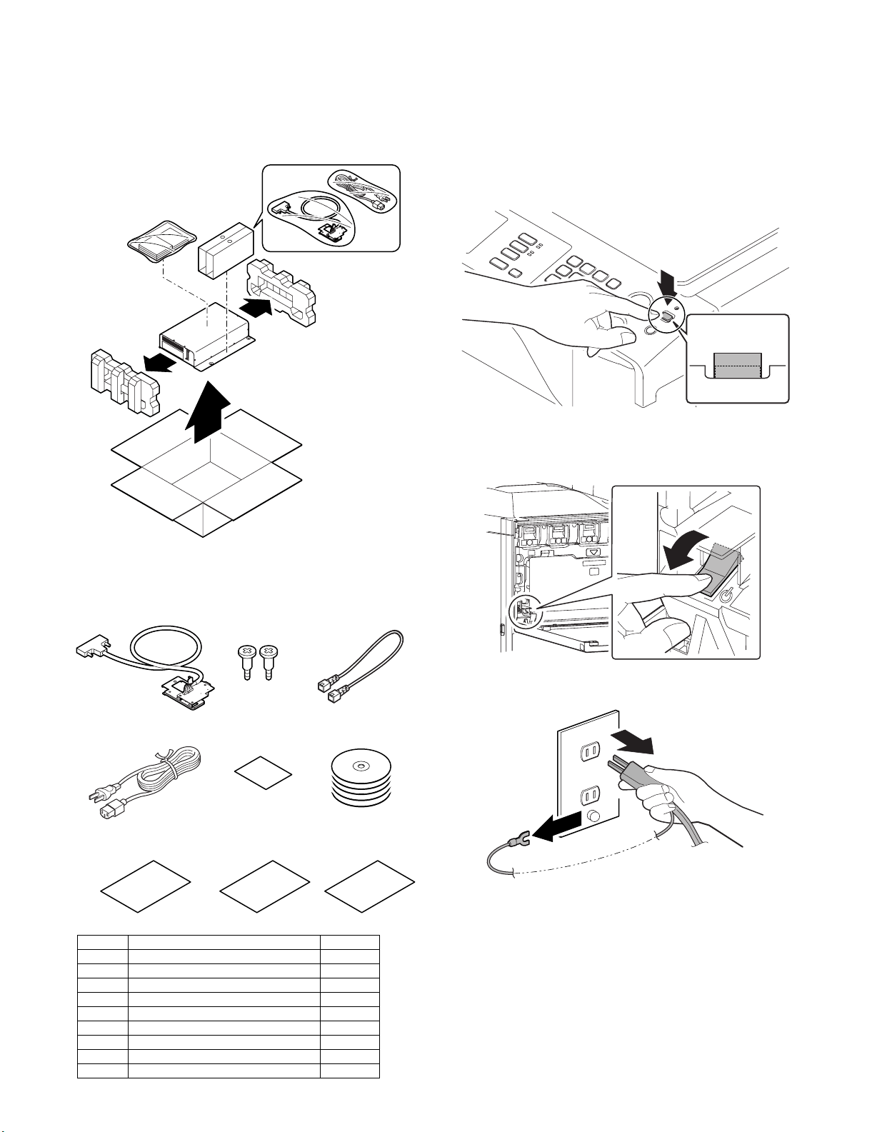
1. Unpacking
A. Removal of the print controller unit
1) Remove the print controller unit.
2. Installation
Service Manual
<Note before installation>
* Start installation after checking that the LINE indicator and the
DATA indicator below it on the operation panel are neither lit nor
blinking.
A. Turn off the power of the main unit
1) Turn the power switch located on the operation panel to the
"OFF" position.
2) After checking that the operation panel has gone out, open the
front cabinet and turn the main power switch to the “OFF” opsition.
B. Check the packed items
• Check that all the items shown in 1) are included in the package.
1
4
78
No. Names of bundles Quantity
1 I/F unit 1
2 Step screw 2
3 LAN cable (cross cable) 1
4 AC power cable 1
5 Caution label 1
6 CD-ROM 5
7 Quick guide 1
8 Release notes 1
9 KODAK chart 1
23
5
6
9
OFF
3) Remove the power plug of the main unit from the outlet.
MX-PEX1 Unpacking, installtion 1 – 1
Page 3
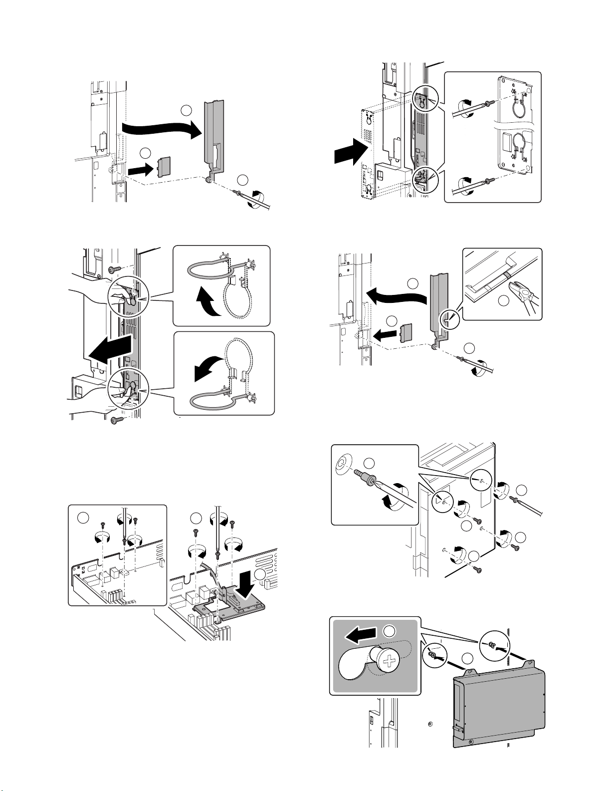
B. Install of the I/F unit
1) Remove the ozone filter cover. Remove the screws, and
remove the right rear cabinet cover.
3
1
2
2) Remove the screws, and pull out the MFP cnt PWB unit.
4) Restore the MFP cnt PWB unit to the main unit, and fix with the
screws.
5) Cut out the cut-out portion of the right rear cabinet cover for
cable along the perforated line. Attach the right rear cabinet
cover, and fix with the screw. Attach the ozone filter cover.
2
1
4
3) Remove the three screws of the MFP cnt PWB. Install the I/F
unit (package part No. 1) with the three screws that was
detached from MFP cnt PWB.
* When installing the I/F unit, use an extreme care to make
the sheet metal not come in contact with the MFP cnt PWB.
1
3
2
3
D01000221202G
C. Installation of the printer controller
1) Remove the four screws from the rear cabinet. Attach two step
screws (package part No. 1) to the two positions in four positions where the fixing screws have been removed.
2
1
1
1
1
2) Engage the printer controller unit with the step screws, and
slide it to the right door side.
2
MX-PEX1 Unpacking, installtion 1 – 2
1
Page 4

3) Fix the print controller unit using the two screws of the four
ON
ON
screws removed in step 1.
D. Connector connection
1) Connect the cable (A) of the I/F unit, the LAN cable (package
part No. 3), and the AC power cord (C) (package part No. 4).
B
2) Insert the power plug of the main unit to the outlet.
3) Turn on the power switch of the print controller unit.
ON
A
C
E. Caution label attachment
1) Attach the caution label (package part No. 5) near a AC power
cord inlet of the main unit.
F. Turn on the power switch of the print
controller unit and the main unit
1) Insert the power plug of the print controller unit into the power
outlet.
4) Open the front cabinet. Turn ON the power switch in the front
cabinet of the main unit.
ON
5) Turn ON the power switch on the operation panel.
MX-PEX1 Unpacking, installtion 1 – 3
Page 5

G. Note for network setting and calibration re-
setting
CAUTION: After the MX-PEX1 is installed, be sure the setting of
CAUTION:
1) System setting → Printer Setting (administrator area) → Fiery
2) After the initial setting and automatic reboot → Printer Setting
(1) About the Fiery Setting
Refer to the configuration manual "SETTING UP THE FIERY
X3ETY2 FROM THE COPIER TOUCH PANEL".
(2) About the calibration
Refer to the color printing manual "Calibration".
1) To execute the calibration from the touch panel of Copier, refer
2) To execute the calibration with a color measurement meter,
items as follows again.
(Reconfiguration in setting is required, because the
information that had been keeping before installation is initialized.)
Setting → Carry out the initial setting from Fiery menu.
(administrator area) → Fiery Setting → Carry out the calibration from Fiery menu again.
to the "Calibrating from the Fiery X3eTY2 copier touch panel".
refer to the "Calibrating with ColorWise Pro Tools Calibrator".
MX-PEX1 Unpacking, installtion 1 – 4
Page 6

LEAD-FREE SOLDER
The PWB’s of this model employs lead-free solder. The “LF” marks indicated on the PWB’s and the Service Manual mean “Lead-Free” solder.
The alphabet following the LF mark shows the kind of lead-free solder.
Example:
<Solder composition code of lead-free solder>
Solder composition
Sn-Ag-Cu
Sn-Ag-Bi
Sn-Ag-Bi-Cu
Sn-Zn-Bi
Sn-In-Ag-Bi
Sn-Cu-Ni
Sn-Ag-Sb
Bi-Sn-Ag-P
Bi-Sn-Ag
5mm
Lead-Free
Solder composition
code (Refer to the
table at the right.)
a
(1) NOTE FOR THE USE OF LEAD-FREE SOLDER THREAD
When repairing a lead-free solder PWB, use lead-free solder thread.
Never use conventional lead solder thread, which may cause a breakdown or an accident.
Since the melting point of lead-free solder thread is about 40°C higher than that of conventional lead solder thread, the use of the
exclusive-use soldering iron is recommendable.
Solder composition code
a
b
z
i
n
s
p
(2) NOTE FOR SOLDERING WORK
Since the melting point of lead-free solder is about 220°C, which is about 40°C higher than that of conventional lead solder, and its soldering
capacity is inferior to conventional one, it is apt to keep the soldering iron in contact with the PWB for longer time. This may cause land
separation or may exceed the heat-resistive temperature of components. Use enough care to separate the soldering iron from the PWB when
completion of soldering is confirmed.
Since lead-free solder includes a greater quantity of tin, the iron tip may corrode easily. Turn ON/OFF the soldering iron power frequently.
If different-kind solder remains on the soldering iron tip, it is melted together with lead-free solder. To avoid this, clean the soldering iron
tip after completion of soldering work.
If the soldering iron tip is discolored black during soldering work, clean and file the tip with steel wool or a fine filer.
COPYRIGHT©XXXX BYSHARP CORPORATION
ALL RIGHTS RESERVED.
No part of this publication may be reproduced,
stored in a retrieval system, or transmitted in
any form or by any means, electronic, mechanical,
photocopying, recording, or otherwise, without
prior written permission of the publisher.
Page 7

CAUTION FOR BATTERY REPLACEMENT
(Danish) ADVARSEL !
Lithiumbatteri – Eksplosionsfare ved fejlagtig håndtering.
(English) Caution !
Dispose of used batteries according to manufacturer’s instructions.
(Finnish) VAROITUS
Paristo voi räjähtää, jos se on virheellisesti asennettu.
Vaihda paristo ainoastaan laitevalmistajan suosittelemaan
(French) ATTENTION
Il y a danger d’explosion s’ il y a remplacement incorrect
de la batterie. Remplacer uniquement avec une batterie du
Mettre au rebut les batteries usagées conformément aux
(Swedish) VARNING
(German) Achtung
Explosionsgefahr bei Verwendung inkorrekter Batterien.
Als Ersatzbatterien dürfen nur Batterien vom gleichen Typ oder
vom Hersteller empfohlene Batterien verwendet werden.
Entsorgung der gebrauchten Batterien nur nach den vom
Udskiftning må kun ske med batteri
af samme fabrikat o g type.
Levér det brugte batteri tilbage til leverandoren.
Danger of explosion if battery is incorrectly replaced.
Replace only with the same or equivalent type
recommended by the manufacturer.
tyyppiin. Hävitä käytetty paristo valmistajan ohjeiden
mukaisesti.
même type ou d’un type équivalent recommandé par
le constructeur.
instructions du fabricant.
Explosionsfara vid felaktigt batteribyte.
Använd samma batterityp eller en ekvivalent
typ som rekommenderas av apparattillverkaren.
Kassera använt batteri enligt fabrikantens
instruktion.
Hersteller angegebenen Anweisungen.
CAUTION FOR BATTERY DISPOSAL
(For USA, CANADA)
THIS PRODUCT CONTAINS A LITHIUM PRIMARY
(MANGANESS DIOXIDE) MEMORY BACK-UP BATTERY
THAT MUST BE DISPOSED OF PROPERLY. REMOVE THE
BATTERY FROM THE PRODUCT AND CONTACT YOUR
LOCAL ENVIRONMENTAL AGENCIES FOR INFORMATION
ON RECYCLING AND DISPOSAL OPTIONS.
CE PRODUIT CONTIENT UNE PILE DE SAUVEGARDE DE
MÉMOIRE LITHIUM PRIMAIRE (DIOXYDE DE MANGANÈSE)
QUI DOIT ÊTRE TRAITÉE CORRECTEMENT. ENLEVEZ LA
PILE DU PRODUIT ET PRENEZ CONTACT AVEC VOTRE
AGENCE ENVIRONNEMENTALE LOCALE POUR DES
INFORMATIONS SUR LES MÉTHODES DE RECYCLAGE ET
“BATTERY DISPOSAL”
“TRAITEMENT DES PILES USAGÉES”
DE TRAITEMENT.
* Applicable for model that uses battery.
Page 8

COPYRIGHT © 2006 BY SHARP CORPORATION
All rights reserved.
Printed in Japan.
No part of this publication may be reproduced,
stored in a retrieval system, or transmitted,
in any form or by any means,
electronic; mechanical; photocopying; recording or otherwise
without prior written permission of the publisher.
Trademark acknowledgements
Microsoft®Windows®operating system is a trademark or copyright of Microsoft
Corporation in the U.S.A. and other countries.
®
• Windows
Windows
Explorer
other countries.
• IBM and PC/AT are trademarks of International Business Machines Corporation.
• Acrobat
re
reserved. Adobe, the Adobe logo, Acrobat, and the Acrobat logo are trademarks of
Adobe Systems Incorporated.
• All other trademarks and copyrights are the property of their respective owners.
95, Windows®98, Windows®Me, Windows NT®4.0, Windows®2000,
®
XP, Windows®2000 Server, Windows®Server 2003 and Internet
®
are trademarks or copyrights of Microsoft Corporation in the U.S.A. and
®
Reader Copyright®1987- 2002 Adobe Systems Incorporated. All rights
SHARP CORPORATION
Digital Document System Group
CS Promotion Center
Yamatokoriyama, Nara 639-1186,
Japan
 Loading...