

Page 1
User's Guide
MODEL:
MX-M850
MX-M950
MX-M1100
Page 2

TABLE OF CONTENTS
ABOUT THIS MANUAL . . . . . . . . . . . . . . . . . . . . . . . . 4
• MANUALS PROVIDED WITH THE MACHINE . . . 4
BEFORE USING THE MACHINE
1
PART NAMES AND FUNCTIONS . . . . . . . . . . . . . . . . 6
• EXTERIOR . . . . . . . . . . . . . . . . . . . . . . . . . . . . . . . 6
• INSIDE AND CONNECTOR . . . . . . . . . . . . . . . . . . 8
• AUTOMATIC DOCUMENT FEEDER AND
DOCUMENT GLASS . . . . . . . . . . . . . . . . . . . . . . . 9
• OPERATION PANEL . . . . . . . . . . . . . . . . . . . . . . 10
TOUCH PANEL . . . . . . . . . . . . . . . . . . . . . . . . . . . . . 12
• USING THE TOUCH PANEL . . . . . . . . . . . . . . . . 12
• USING THE TOUCH PANEL (System
Settings) . . . . . . . . . . . . . . . . . . . . . . . . . . . . . . . . 14
• SYSTEM BAR . . . . . . . . . . . . . . . . . . . . . . . . . . . 15
PRINT/SEND STATUS (JOB STATUS) . . . . . . . . . . . 16
• STATUS INDICATORS . . . . . . . . . . . . . . . . . . . . 17
TURNING THE POWER ON AND OFF . . . . . . . . . . . 18
• ENERGY SAVE FUNCTIONS . . . . . . . . . . . . . . . 19
• [POWER SAVE] KEY . . . . . . . . . . . . . . . . . . . . . . 19
USER AUTHENTICATION . . . . . . . . . . . . . . . . . . . . . 20
• AUTHENTICATION BY USER NUMBER. . . . . . . 20
• AUTHENTICATION BY LOGIN NAME /
PASSWORD. . . . . . . . . . . . . . . . . . . . . . . . . . . . . 22
HOME SCREEN . . . . . . . . . . . . . . . . . . . . . . . . . . . . . 25
PERIPHERAL DEVICE TRAYS . . . . . . . . . . . . . . . . . 35
• TRAY LOCATIONS AND NAMES . . . . . . . . . . . . 35
• PAPER THAT CAN BE USED IN THE
PERIPHERAL DEVICE TRAYS . . . . . . . . . . . . . . 36
• TRAY SETTINGS FOR THE LARGE
CAPACITY TRAYS (MX-LCX4) . . . . . . . . . . . . . . 37
• TRAY SETTINGS FOR THE LARGE
CAPACITY TRAYS (MX-LCX5) . . . . . . . . . . . . . . 40
• TRAY SETTINGS FOR THE LARGE
CAPACITY TRAY (MX-LCX6) . . . . . . . . . . . . . . . 43
• TRAY SETTINGS FOR THE LARGE
CAPACITY TRAY (MX-LCX3N) . . . . . . . . . . . . . . 44
LOADING PAPER IN THE BYPASS TRAY . . . . . . . . 48
• IMPORTANT POINTS WHEN USING THE
BYPASS TRAY. . . . . . . . . . . . . . . . . . . . . . . . . . . 52
ORIGINALS
3
PLACING THE ORIGINAL . . . . . . . . . . . . . . . . . . . . . 53
• PLACING ORIGINALS IN THE AUTOMATIC
DOCUMENT FEEDER . . . . . . . . . . . . . . . . . . . . . 53
• PLACING THE ORIGINAL ON THE
DOCUMENT GLASS . . . . . . . . . . . . . . . . . . . . . . 55
PERIPHERAL DEVICES
4
PERIPHERAL DEVICES . . . . . . . . . . . . . . . . . . . . . . 57
LOADING PAPER
2
IMPORTANT POINTS ABOUT PAPER . . . . . . . . . . . 26
• NAMES AND LOCATIONS OF TRAYS . . . . . . . . 26
• THE MEANING OF "R" IN PAPER SIZES . . . . . . 26
• USEABLE PAPER . . . . . . . . . . . . . . . . . . . . . . . . 27
TRAY SETTINGS FOR TRAY 1 AND TRAY 2. . . . . . 29
• LOADING PAPER . . . . . . . . . . . . . . . . . . . . . . . . 29
• CHANGING THE PAPER SIZE . . . . . . . . . . . . . . 30
TRAY SETTINGS FOR TRAY 3 AND TRAY 4. . . . . . 32
• LOADING PAPER AND CHANGING THE
PAPER SIZE . . . . . . . . . . . . . . . . . . . . . . . . . . . . 32
NAMES AND FUNCTIONS OF THE PARTS OF
THE PERIPHERAL DEVICE. . . . . . . . . . . . . . . . . . . . 59
• FINISHER. . . . . . . . . . . . . . . . . . . . . . . . . . . . . . . 59
• SADDLE UNIT . . . . . . . . . . . . . . . . . . . . . . . . . . . 60
• FINISHER (FOR THE MX-M850) / SADDLE
STITCH FINISHER. . . . . . . . . . . . . . . . . . . . . . . . 60
• FOLDING UNIT . . . . . . . . . . . . . . . . . . . . . . . . . . 61
• INSERTER . . . . . . . . . . . . . . . . . . . . . . . . . . . . . . 62
MANUAL FINISHING MODE . . . . . . . . . . . . . . . . . . . 65
• USING MANUAL FINISHING . . . . . . . . . . . . . . . . 66
• STAPLE FUNCTION / SADDLE STITCH
FUNCTION . . . . . . . . . . . . . . . . . . . . . . . . . . . . . . 67
• PUNCH FUNCTION . . . . . . . . . . . . . . . . . . . . . . . 69
• PAPER LOADING ORIENTATION (FOR THE
STAPLE AND PUNCH FUNCTIONS) . . . . . . . . . 69
• PAPER FOLDING FUNCTION. . . . . . . . . . . . . . . 70
• PAPER LOADING ORIENTATION (FOR
FOLDING) . . . . . . . . . . . . . . . . . . . . . . . . . . . . . . 70
2
Page 3

SHARP OSA . . . . . . . . . . . . . . . . . . . . . . . . . . . . . . . . 71
• APPLICATION COMMUNICATION MODULE
(MX-AMX2). . . . . . . . . . . . . . . . . . . . . . . . . . . . . . 71
• EXTERNAL ACCOUNT MODULE (MX-AMX3) . . 72
SYSTEM SETTINGS
5
ACCESSING THE SYSTEM SETTINGS . . . . . . . . . . 74
SYSTEM SETTINGS LIST . . . . . . . . . . . . . . . . . . . . . 75
TOTAL COUNT . . . . . . . . . . . . . . . . . . . . . . . . . . . . . 77
• JOB COUNT. . . . . . . . . . . . . . . . . . . . . . . . . . . . . 77
• DEVICE COUNT . . . . . . . . . . . . . . . . . . . . . . . . . 77
DEFAULT SETTINGS . . . . . . . . . . . . . . . . . . . . . . . . 78
• CLOCK ADJUST . . . . . . . . . . . . . . . . . . . . . . . . . 78
• KEYBOARD SELECT. . . . . . . . . . . . . . . . . . . . . . 79
LIST PRINT (USER) . . . . . . . . . . . . . . . . . . . . . . . . . . 79
PAPER TRAY SETTINGS . . . . . . . . . . . . . . . . . . . . . 80
• TRAY SETTINGS . . . . . . . . . . . . . . . . . . . . . . . . . 80
• PAPER TYPE REGISTRATION . . . . . . . . . . . . . . 84
• AUTO TRAY SWITCHING . . . . . . . . . . . . . . . . . . 84
USB-DEVICE CHECK . . . . . . . . . . . . . . . . . . . . . . . . 84
USER CONTROL . . . . . . . . . . . . . . . . . . . . . . . . . . . . 85
• MODIFY USER INFORMATION . . . . . . . . . . . . . 85
TROUBLESHOOTING
6
• PROBLEMS RELATED TO MACHINE
OPERATION . . . . . . . . . . . . . . . . . . . . . . . . . . . . 87
• PROBLEMS RELATED TO PAPER FEEDING
AND OUTPUT . . . . . . . . . . . . . . . . . . . . . . . . . . . 90
• PROBLEMS RELATED TO QUALITY / PRINT
RESULTS . . . . . . . . . . . . . . . . . . . . . . . . . . . . . . . 92
• PROBLEMS RELATED TO PERIPHERAL
DEVICES . . . . . . . . . . . . . . . . . . . . . . . . . . . . . . . 93
• OTHER PROBLEMS . . . . . . . . . . . . . . . . . . . . . . 96
ENTERING TEXT
7
FUNCTIONS OF THE MAIN KEYS . . . . . . . . . . . . . . 97
• ENTERING TEXT FROM AN EXTERNAL
KEYBOARD . . . . . . . . . . . . . . . . . . . . . . . . . . . . . 98
3
Page 4
ABOUT THIS MANUAL
Please note
• Considerable care has been taken in preparing this manual. If you have any comments or concerns about the manual, please
contact your dealer or nearest SHARP Service Department.
• This product has undergone strict quality control and inspection procedures. In the unlikely event that a defect or other problem
is discovered, please contact your dealer or nearest SHARP Service Department.
• Aside from instances provided for by law, SHARP is not responsible for failures occurring during the use of the product or its
options, or failures due to incorrect operation of the product and its options, or other failures, or for any damage that occurs due
to use of the product.
Warning
• Reproduction, adaptation or translation of the contents of the manual without prior written permission is prohibited, except as
allowed under copyright laws.
• All information in this manual is subject to change without notice.
Illustrations and the operation panel and touch panel shown in this manual
The peripheral devices are generally optional, however, some models include certain peripheral devices as standard equipment.
The explanations in this manual assume that a finisher, punch module, saddle unit, folding unit, inserter, large capacity trays, and
bypass tray are installed on the MX-M1100.
For some functions and procedures, the explanations assume that devices other than the above are installed.
The display screens, messages, and key names shown in the manual may differ from those on the actual machine
due to product improvements and modifications.
MANUALS PROVIDED WITH THE MACHINE
Printed manuals and manuals stored in PDF format on the machine's hard drive are provided with the machine. When
using the machine, read the appropriate manual for the feature you are using.
Printed manuals
Manual name Contents
Safety Guide
Software Setup
Guide
Quick Start Guide
Maintenance Guide
This manual contains instructions for using the machine safely and lists the specifications of the machine
and its peripheral devices.
This manual explains how to install and configure the software that is required to use the printer function
and other functions of the machine that are used from a computer.
This manual provides easy-to-understand explanations of all the functions of the machine in a single
volume.
Detailed explanations of each of the functions can be found in the manuals in PDF format.
This manual explains maintenance procedures such as how to replace supplies and remove paper
misfeeds.
4
Page 5
Operation manuals in PDF format
The manuals in PDF format provide detailed explanations of the procedures for using the machine in each mode. To
view the PDF manuals, download them from the hard drive in the machine. The procedure for downloading the manuals
is explained in "How to download the manuals in PDF format" in the Quick Start Guide.
Manual name Contents
User's Guide
(This manual)
Copier Guide
Printer Guide This manual provides detailed explanations of the procedures for using the print function.
Image Send Guide
Document Filing
Guide
Administrator's
Guide
This manual explains the basic procedures for using the machine, such as how to load paper.
This manual provides detailed explanations of the procedures for using the copy function.
This manual provides detailed explanations of the procedures for using the image send function (scan,
USB memory scan, Internet fax, fax, and data entry).
This manual provides detailed explanations of the procedures for using the document filing function. The
document filing function allows you to save the document data of a copy or fax job, or the data of a print
job, as a file on the machine's hard drive. The file can be called up as needed.
This manual explains the settings and functions that are used to manage and control the machine, such
as the system settings that require administrator rights.
Icons used in the manuals
The icons in the manuals indicate the following types of information:
Warning
Caution
This alerts you to a situation where there is a risk of human death or injury.
This alerts you to a situation where there is a risk of human injury or property damage.
This alerts you to a situation where
there is a risk of machine damage or
failure.
This provides a supplemental
explanation of a function or procedure.
This explains how to cancel or correct
an operation.
This indicates the name of a system setting and provides a brief
explanation of the setting.
When "System Settings:" appears:
A general setting is explained.
When "System Settings (Administrator):" appears:
A setting that can only be configured by an administrator is
explained. For detailed information on each system setting, see
the Administrator's Guide.
5
Page 6
BEFORE USING THE MACHINE
1
This chapter provides basic information about the machine. Please read this chapter before using the machine.
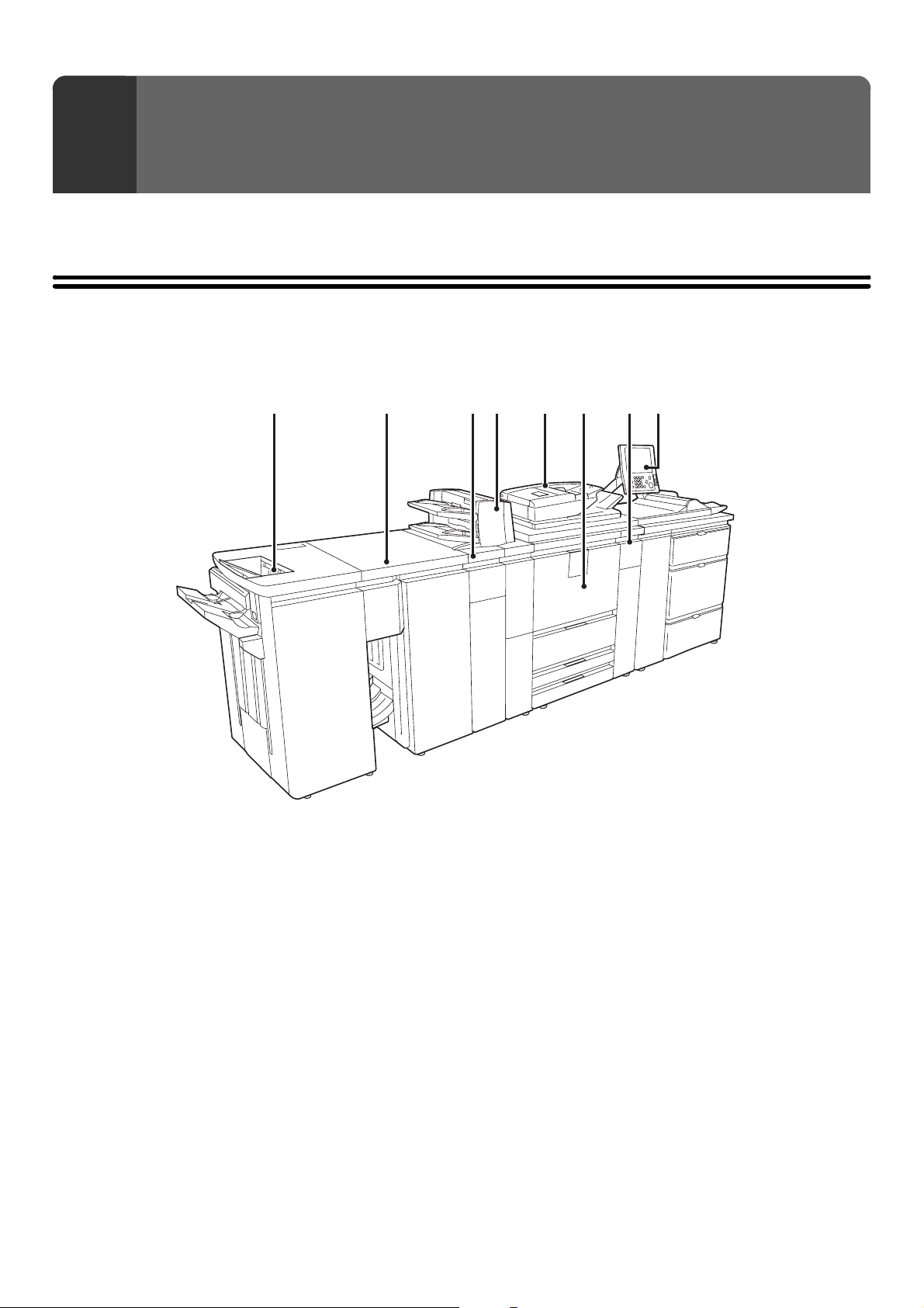
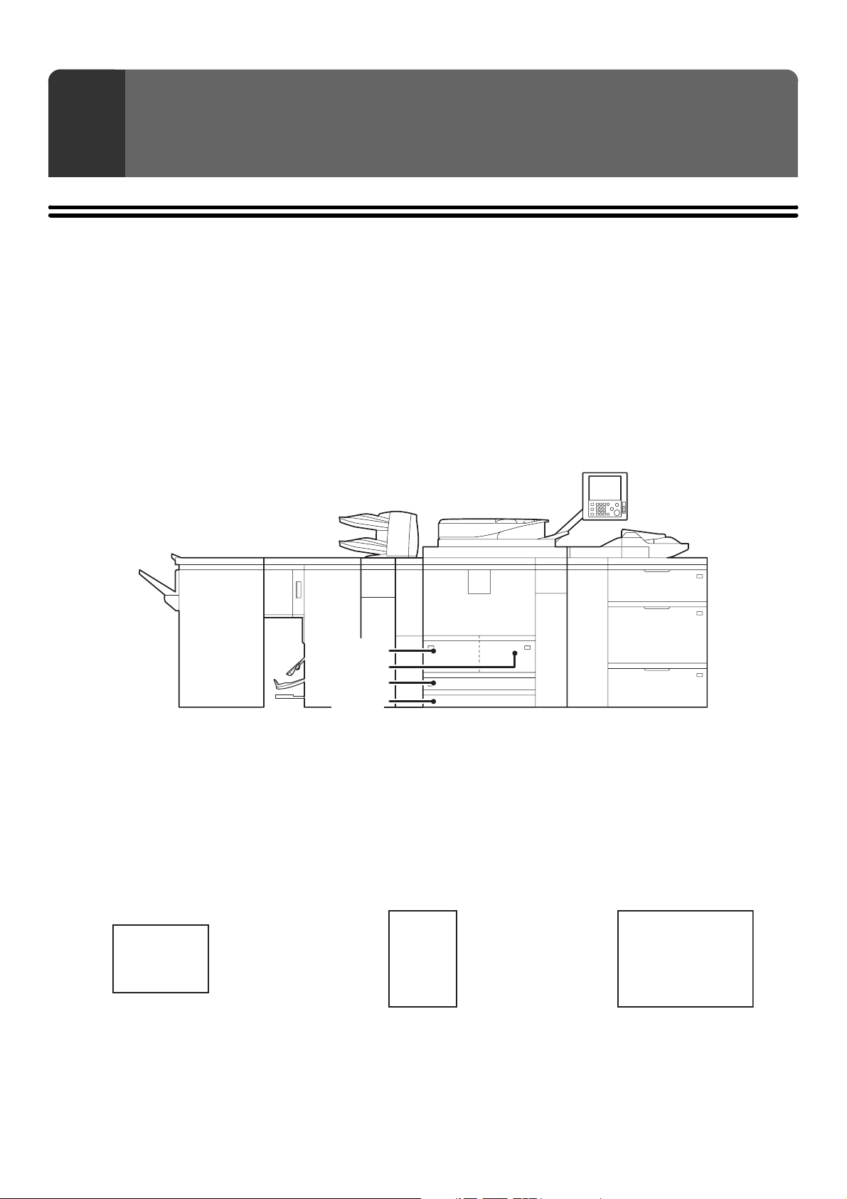
PART NAMES AND FUNCTIONS
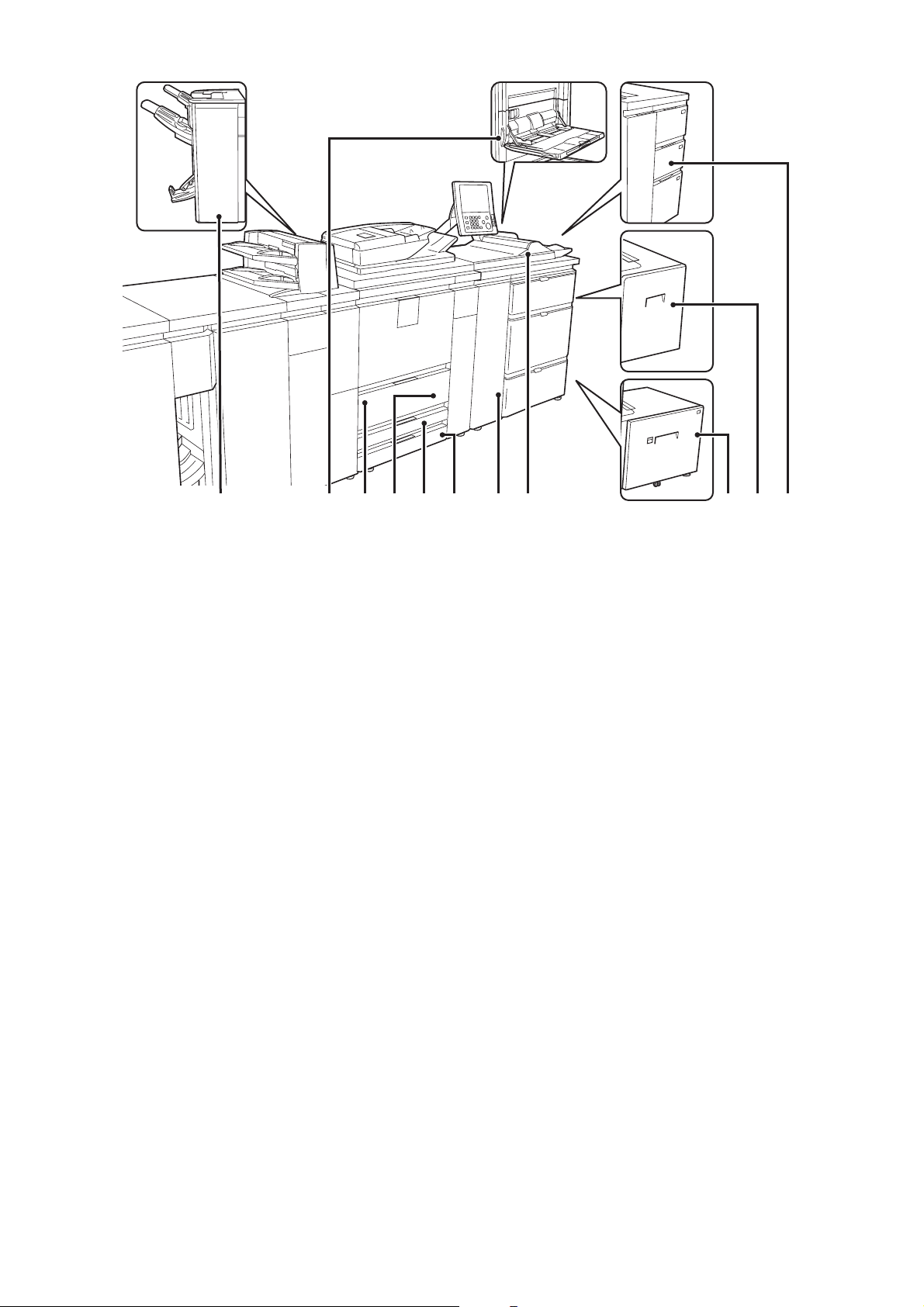
EXTERIOR
(1) (2) (3)
(1) Finisher*
This can be used to staple output. The optional punch
module can be installed to punch holes in output.
☞ FINISHER (page 59)
(2) Saddle unit
The output is folded at the center. The saddle stitch
function staples output at the centerline.
*
☞ SADDLE UNIT (page 60)
(3) Folding unit
This folds output.
*
☞ FOLDING UNIT (page 61)
(4) Inserter*
Paper loaded in the inserter can be inserted into output
from the machine as covers and inserts.
☞ INSERTER (page 62)
(4) (5) (8)(7)(6)
(5) Automatic document feeder
This automatically feeds and scans multiple originals. Both
sides of 2-sided originals can be automatically scanned.
☞ PLACING ORIGINALS IN THE AUTOMATIC
DOCUMENT FEEDER (page 53)
(6) Front cover
Open this to remove a paper misfeed from the conveyor
unit or to switch the main power switch on and off.
☞ TURNING THE POWER ON AND OFF (page 18)
(7) Toner cartridge installation cover
Open this cover to replace a toner cartridge.
(8) Operation panel
This is used to select functions and enter the number of
copies.
☞ OPERATION PANEL (page 10)
*Peripheral device.
6
Page 7
(11)(9) (12) (13) (15) (16)(14)(10) (17) (18) (19)
(9)
Finisher (for MX-M850) / Saddle stitch finisher*
This can be used to staple output. The punch module can
be installed to punch holes in output. The saddle stitch
finisher can automatically staple output at the centerline
and fold the pages to create a pamphlet.
☞ FINISHER (FOR THE MX-M850) / SADDLE STITCH
FINISHER (page 60)
(10) Bypass tray (MX-MFX1)*
When using the bypass tray, insert the paper from here.
If the paper is larger than 8-1/2" x 11"R (A4R), be sure to
pull out the extension tray.
When the large capacity trays are installed, this cannot
be installed.
☞
LOADING PAPER IN THE BYPASS TRAY (page 48)
(11) Tray 1 (left side)
This holds paper. Up to 1200 sheets of paper can be
loaded.
☞ TRAY SETTINGS FOR TRAY 1 AND TRAY 2 (page
29)
(12) Tray 2 (right side)
This holds paper. Up to 800 sheets of paper can be
loaded.
☞ TRAY SETTINGS FOR TRAY 1 AND TRAY 2 (page
29)
(13) Tray 3
This holds paper. Transparency film, tab paper, and
other special media can also be loaded. Up to 500 sheets
of paper can be loaded.
☞ TRAY SETTINGS FOR TRAY 3 AND TRAY 4 (page
32)
(14) Tray 4
This holds paper. Transparency film, tab paper, and
other special media can also be loaded. Up to 500 sheets
of paper can be loaded.
☞ TRAY SETTINGS FOR TRAY 3 AND TRAY 4 (page
32)
(15) Large capacity trays (MX-LCX5)*
This holds paper. Up to 4000 sheets of paper can be
loaded.
☞
TRAY SETTINGS FOR THE LARGE CAPACITY
TRAYS (MX-LCX5) (page 40)
(16) Bypass tray (MX-MFX2)*
Bypass tray that can be installed when the large capacity
trays are installed. Use this tray to feed paper manually.
When loading paper larger than 8-1/2" x 11"R or A4R, be
sure to pull out the bypass tray extension.
☞
LOADING PAPER IN THE BYPASS TRAY (page 48)
(17) Large capacity tray (MX-LCX3N*)
This can be used on the MX-M850.
The bypass tray (MX-MFX1) is required. Up to 3000
sheets of paper can be loaded.
☞
TRAY SETTINGS FOR THE LARGE CAPACITY
TRAY (MX-LCX3N)
(18) Large capacity tray (MX-LCX6)*
The bypass tray (MX-MFX1) is required.
This holds paper. Up to 3500 sheets of paper can be loaded.
☞
TRAY SETTINGS FOR THE LARGE CAPACITY
TRAY (MX-LCX6) (page 43)
(19) Large capacity trays (MX-LCX4)*
This holds paper. Up to 4550 sheets of paper can be
loaded.
(page
44)
☞ TRAY SETTINGS FOR THE LARGE CAPACITY
TRAYS (MX-LCX4) (page 37)
*Peripheral device.
7
Page 8
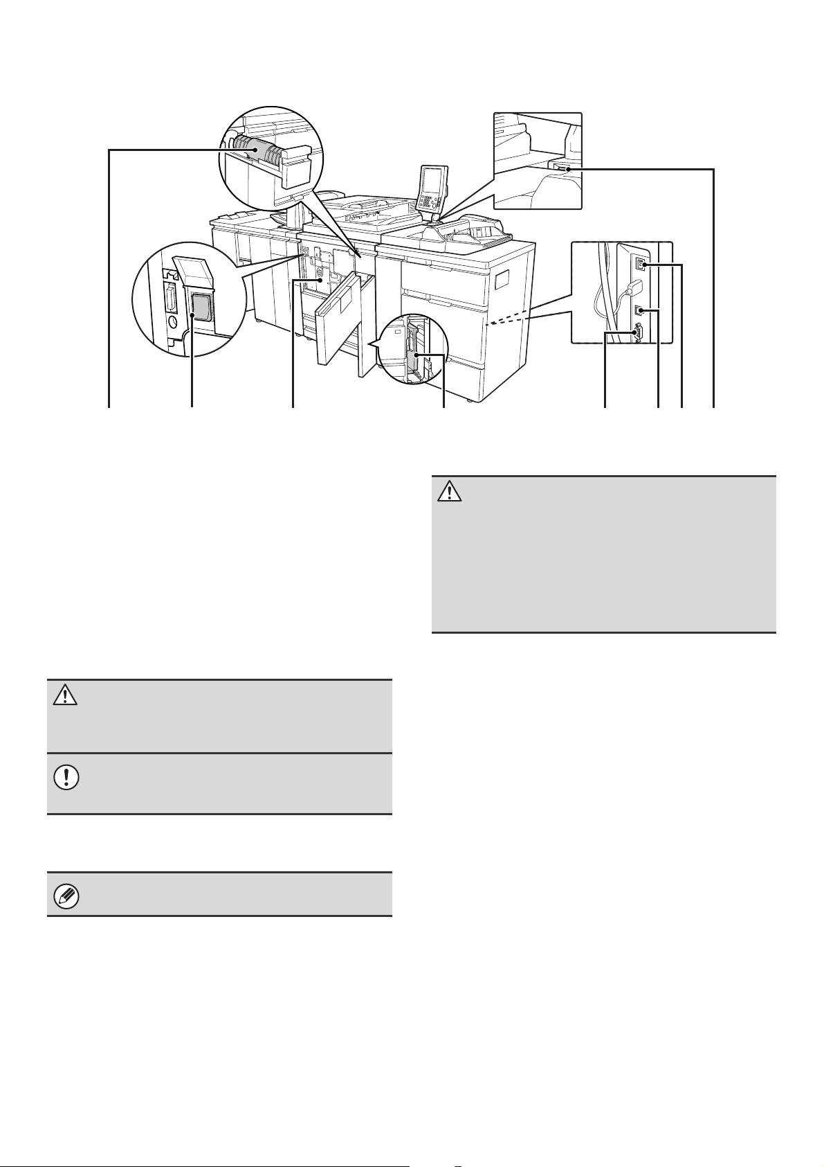
INSIDE AND CONNECTOR
(20) (22) (23) (24)(21) (27)(26)(25)
(20) Toner cartridges
These contain toner for printing. When the toner runs out
in the cartridge, replace the cartridge with a new
cartridge.
(21) Main power switch
This is used to power on the machine.
When using the fax or Internet fax functions, keep this
switch in the "on" position.
☞ TURNING THE POWER ON AND OFF (page 18)
(22) Conveyor unit
This contains the fusing unit that fuses the transferred
image to the paper by heat, and the transfer belt that is
used to transfer the image to the paper.
Caution
The fusing unit is hot. Take care not to burn yourself
when removing a paper misfeed.
Do not touch the transfer belt or allow it to be
damaged.
This may cause a defective image.
(23) Toner collection container
This collects excess toner that remains after printing.
Your service technician will collect the toner collection
container.
(24) Service-only connector
Caution
This connector is for use only by service technicians.
Connecting a cable to this connector may cause the
machine to malfunction.
Important note for service technicians:
The cable connected to the service connector must be
less than 118" (3 m) in length.
(25) USB connector (B type)
A computer can be connected to this connector to use
the machine as a printer.
For the USB cable, use a shielded cable.
(26) LAN connector
Connect the LAN cable to this connector when the
machine is used on a network.
For the LAN cable, use a shielded type cable.
(27) USB connector (A type)
This is used to connect a USB device such as USB
memory to the machine.
For the USB cable, use a shielded cable.
8
Page 9
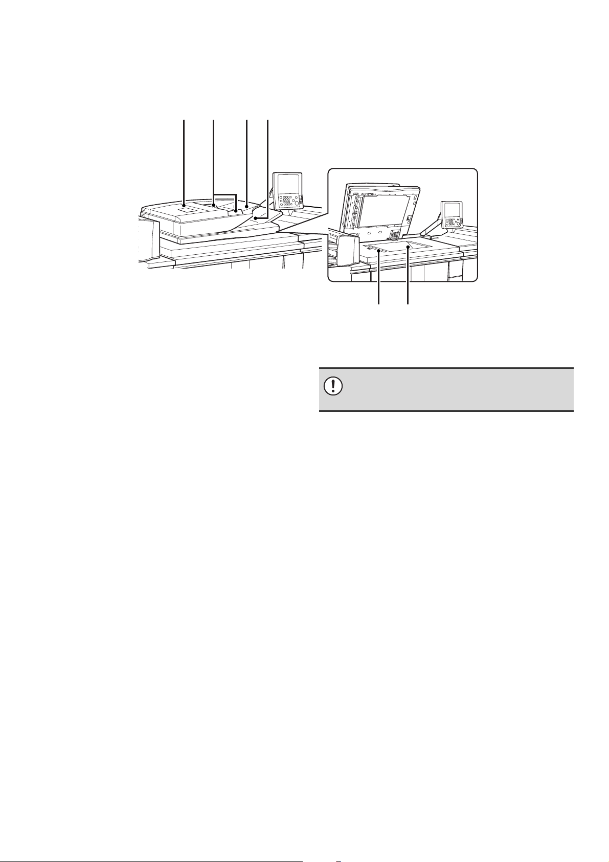
AUTOMATIC DOCUMENT FEEDER AND DOCUMENT
GLASS
(2)(1) (3) (4)
(5)
(6)
(1) Document feeding area cover
Open to remove a misfed original.
(2) Original guides
These help ensure that the original is scanned correctly.
Adjust the guides to the width of the original.
☞ PLACING THE ORIGINAL (page 53)
(3) Document feeder tray
Place originals in this tray. 1-sided originals must be
placed face up.
☞ PLACING THE ORIGINAL (page 53)
(4) Original exit tray
Originals are delivered to this tray after scanning.
(5) Scanning area
Originals placed in the document feeder tray are scanned
here.
Do not allow paper or other material to cover the
scanning area or black sheet next to the scanning
area. This will prevent proper scanning of the original.
(6) Document glass
Use this to scan a book or other thick original that cannot
be fed through the automatic document feeder.
☞ PLACING THE ORIGINAL ON THE DOCUMENT
GLASS (page 55)
9
Page 10
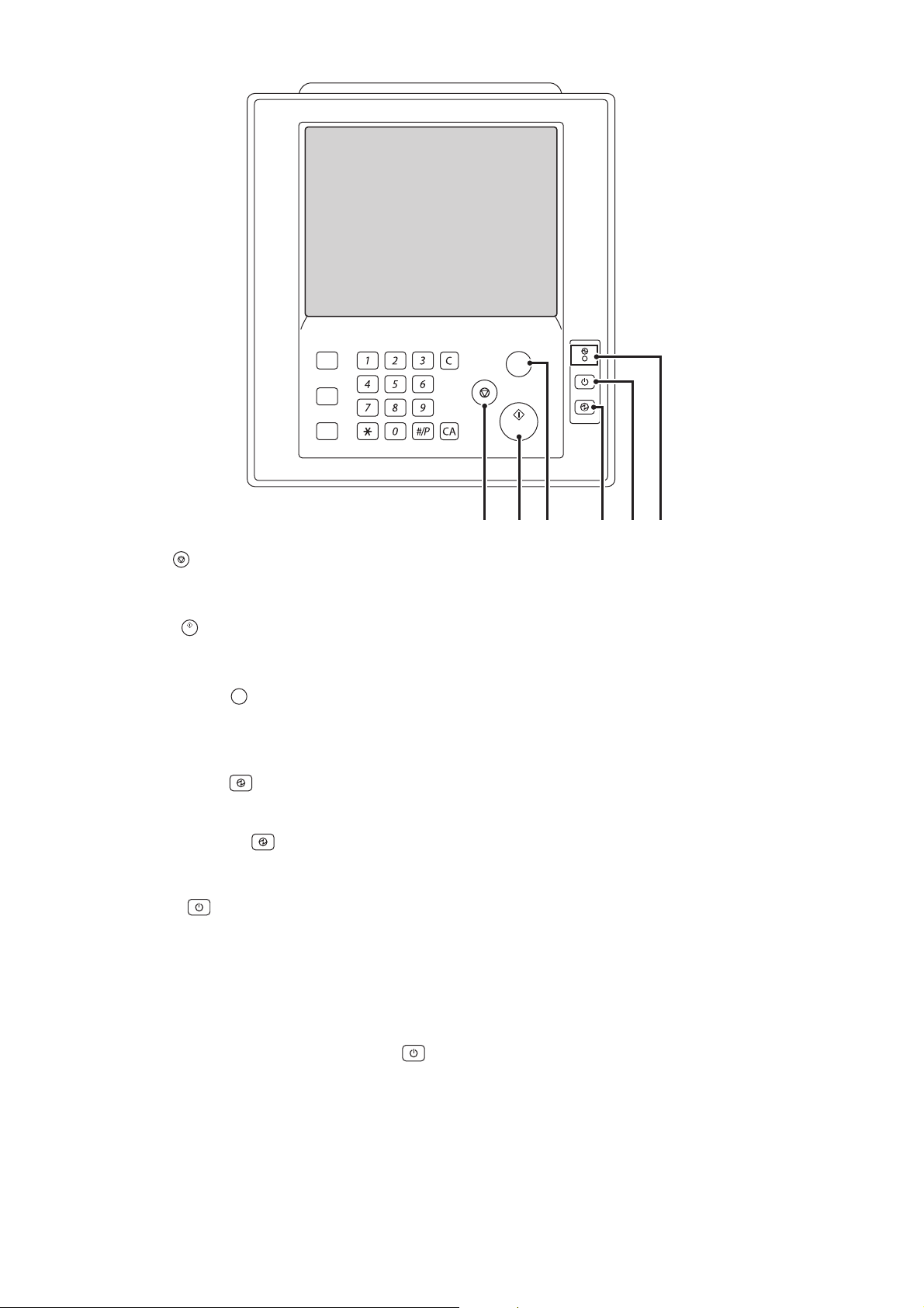
OPERATION PANEL
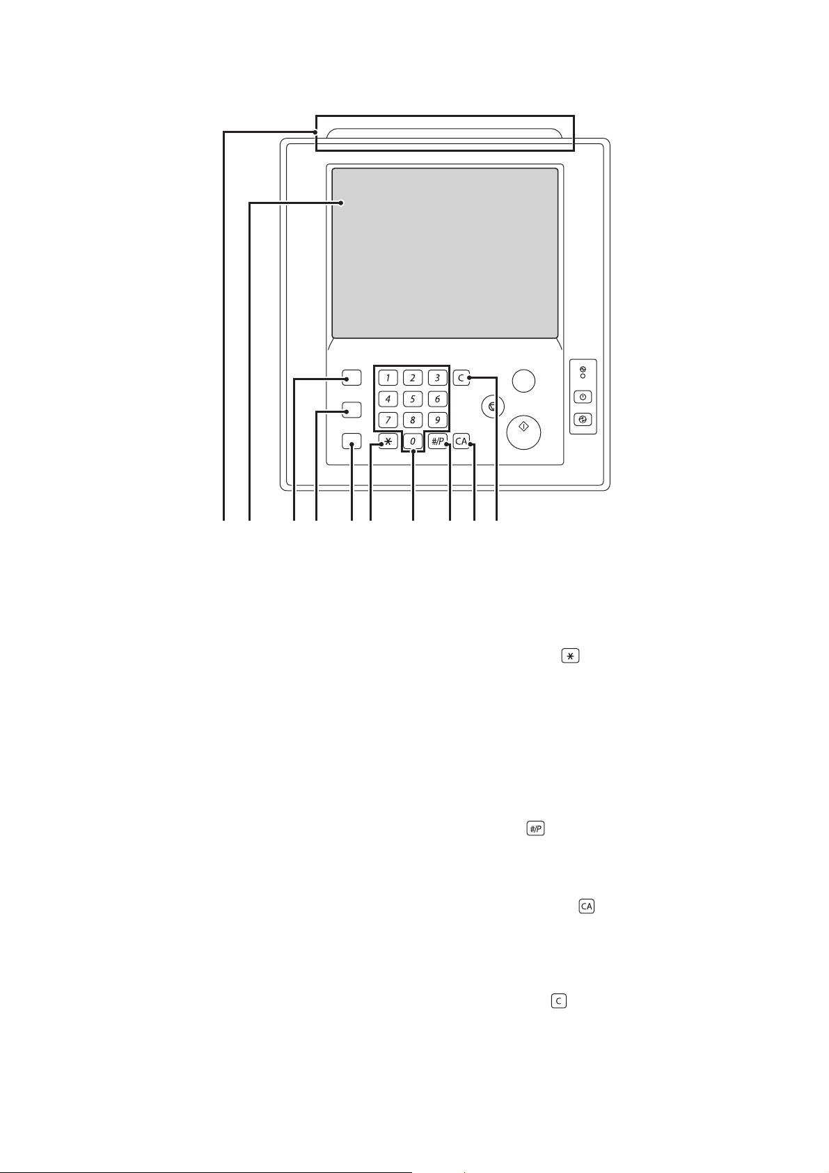
(1) Status indicators
Green and red indicators will light or blink to indicate the
machine's status. When the green indicator lights or
blinks, the machine is operating normally. When the red
indicator lights or blinks, an error has occurred.
☞ STATUS INDICATORS (page 17)
(2) Touch panel
Messages and keys appear in the touch panel display.
Touch the displayed keys to perform a variety of
operations.
When a key is touched, a beep sounds and the selected
item is highlighted. This provides confirmation as you
perform an operation.
☞ TOUCH PANEL (page 12)
(3) [HOME] key
Touch this key to display the home screen. Frequently
used settings can be registered in the home screen to
enable quick and easy operation of the machine.
☞ HOME SCREEN (page 25)
(4) [SYSTEM SETTINGS] key
Press this key to display the system settings menu
screen. The system settings are used to configure paper
tray settings, store addresses for transmission
operations, and adjust parameters to make the machine
easier to use.
☞ 5. SYSTEM SETTINGS (page 74)
☞ Administrator's Guide
HOME
SYSTEM
SETTINGS
JOB STATUS
LOGOUT
(5) (6)(1) (2) (3) (4) (7) (8) (9) (10)
(5) [JOB STATUS] key
Press this key to display the job status screen. The job
status screen is used to check information on jobs and to
cancel jobs.
☞ PRINT/SEND STATUS (JOB STATUS) (page 16)
(6) [LOGOUT] key ( )
Press this key to log out after you have logged in and
used the machine. When using the fax function, this key
can also be pressed to send tone signals on a pulse dial
line.
☞ USER AUTHENTICATION (page 20)
(7) Numeric keys
These are used to enter the number of copies, fax
numbers, and other numerical values.
(8) [#/P] key ( )
When using the copy function, press this key to use a job
program. When using the fax function, this key can be
used when dialing.
(9) [CLEAR ALL] key ( )
Press this key to return to the initial operation state.
Use this key when you wish to cancel all settings that
have been selected and start operation from the initial
state.
(10) [CLEAR] key ( )
Press this key to return the number of copies to "0".
PROOF COPY
10
Page 11
HOME
SYSTEM
SETTINGS
JOB STATUS
LOGOUT
(11) [STOP] key ( )
Press this key to stop a copy job or scanning of an
original.
(12) [START] key ( )
Press this key to copy or scan an original. This key is also
used to send a fax in fax mode.
(13) [PROOF COPY] key ( )
PROOF COPY
Use this to make a proof copy. For information on proof
copying, see "CHECKING COPIES BEFORE PRINTING
(Proof Copy)" in the Copier Guide.
(14) [POWER SAVE] key ( ) / indicator
Use this key to put the machine into auto power shut-off
mode to save energy.
The [POWER SAVE] key ( ) blinks when the machine
is in auto power shut-off mode.
☞ [POWER SAVE] KEY (page 19)
PROOF COPY
(12)(11) (13) (14) (15) (16)
(15) [POWER] key ( )
Use this key to turn the machine power on and off.
☞ TURNING THE POWER ON AND OFF (page 18)
(16) Main power indicator
This lights up when the machine's main power switch is
in the "on" position. Normally this lights solid green.
When the machine has the Internet fax or fax function
and the power is turned off with the [POWER] key ( ),
this lights solid orange.
☞ TURNING THE POWER ON AND OFF (page 18)
11
Page 12
TOUCH PANEL
The touch panel (screen) shown in this manual is a descriptive image. The actual screen is slightly different.
USING THE TOUCH PANEL
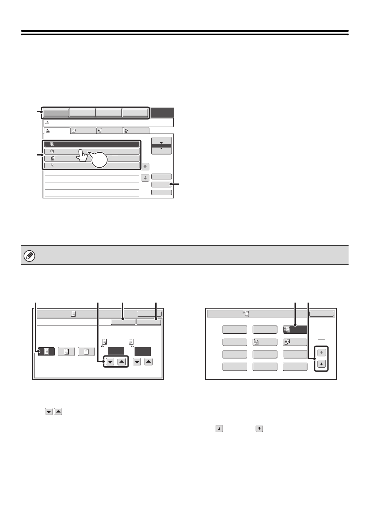
Example 1
(1)
(2)
COPY
Job status screen.
Print Job
3
4
IMAGE SEND
Scan to Fax Job Internet Fax
Job Queue Sets / Progress Status
Copy1 0020 / 0001 Copying
Copy2
Computer01 0002 / 0000
0312345678 0001 / 0000
DOCUMENT
0002 / 0000
Beep
Tone
FILING
Waiting
Waiting
Waiting
MANUAL
FINISHING
1
1
Spool
Job Queue
Complete
Detail
Priority
Stop/Delete
(3)
(1) Mode select keys
Use these keys to switch between copy, image send, document filing, and manual finishing modes.
(2) Settings for each function are easily selected and canceled by touching the keys on the screen with your finger.
When an item is selected, a beep will sound and the item will be highlighted to confirm the selection.
(3) Keys that are grayed out cannot be selected.
If you touch a key that cannot be selected, a double beep will sound.
Example 2
Example 3
(3) (4)(2)(1)
Side 2
1/2
OK
OKCancel
(0~1)
inch
Special Modes
Margin Shift
Right Left Down Side 1
1/2
(0~1)
inch
(1) If the initial state of a key in a screen is highlighted,
the key is selected. To change the selection, touch
one of the other keys to highlight that key.
(2) The keys can be used to increase or
decrease a value. To make a value change quickly,
keep your finger on the key.
(3) Touch this key to cancel a setting.
(4) Touch the [OK] key to enter and save a setting.
(1) (2)
Special Modes
Margin Shift
Pamphlet Copy
Covers/Inserts
Book Copy
Erase
Job
Build
Transparency
Inserts
Tab Copy
Dual Page
Copy
Tandem
Copy
Multi Shot
Card Shot
OK
1
2
(1) Some items in the special modes screen are
selected by simply touching the key of the item.
To cancel a selected item, touch the highlighted key
once again so that it is no longer highlighted.
(2) When settings extend over multiple screens, touch
the key or the key to switch through the
screens.
12
Page 13
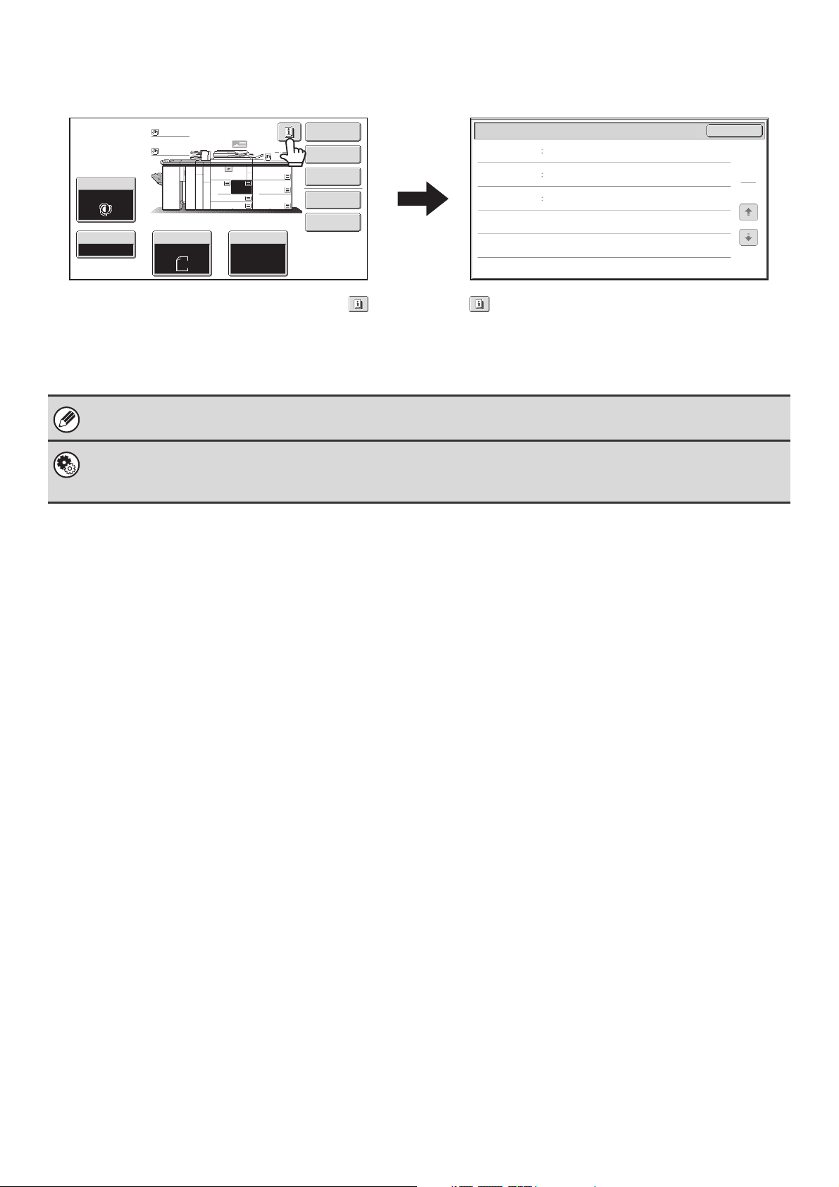
Example 4
Exposure
Auto
Copy Ratio
100%
Plain
Plain
5.
11x17
2.
1.
6.
8½x11
8½x11
3.
4.
Original Paper Select
Auto
8½x11
11x17
8½x14
7.
Auto
8½x11
Plain
11x17
11x17
Plain
8½x11
Special Modes
2-Sided Copy
Output
File
Quick File
When at least one special mode is selected, the key
appears in the base screen.
Function Review
Margin Shift
Erase
Covers/Inserts
Shift:Right
Front:1/2inch/Back:1/2inch
Edge:1/2inch
Center:1/2inch
Front:2-Sided/Back:Insert
Insertion A:10 Page/B:10 Page
The key can be touched to display a list of the
selected special modes.
The above explanations do not apply to the system settings. For information on the screens and procedures for using the
system settings, see "USING THE TOUCH PANEL (System Settings)" (page 14).
System Settings (Administrator): Keys Touch Sound
This is used to adjust the volume of the beep that sounds when keys are touched. The key touch sound can also be turned
off.
OK
1
1
13
Page 14
USING THE TOUCH PANEL (System Settings)
This section explains special operation methods that are common to all system settings.
Some of these steps are omitted in the explanations of each of the system settings, so refer to this section when
configuring a setting.
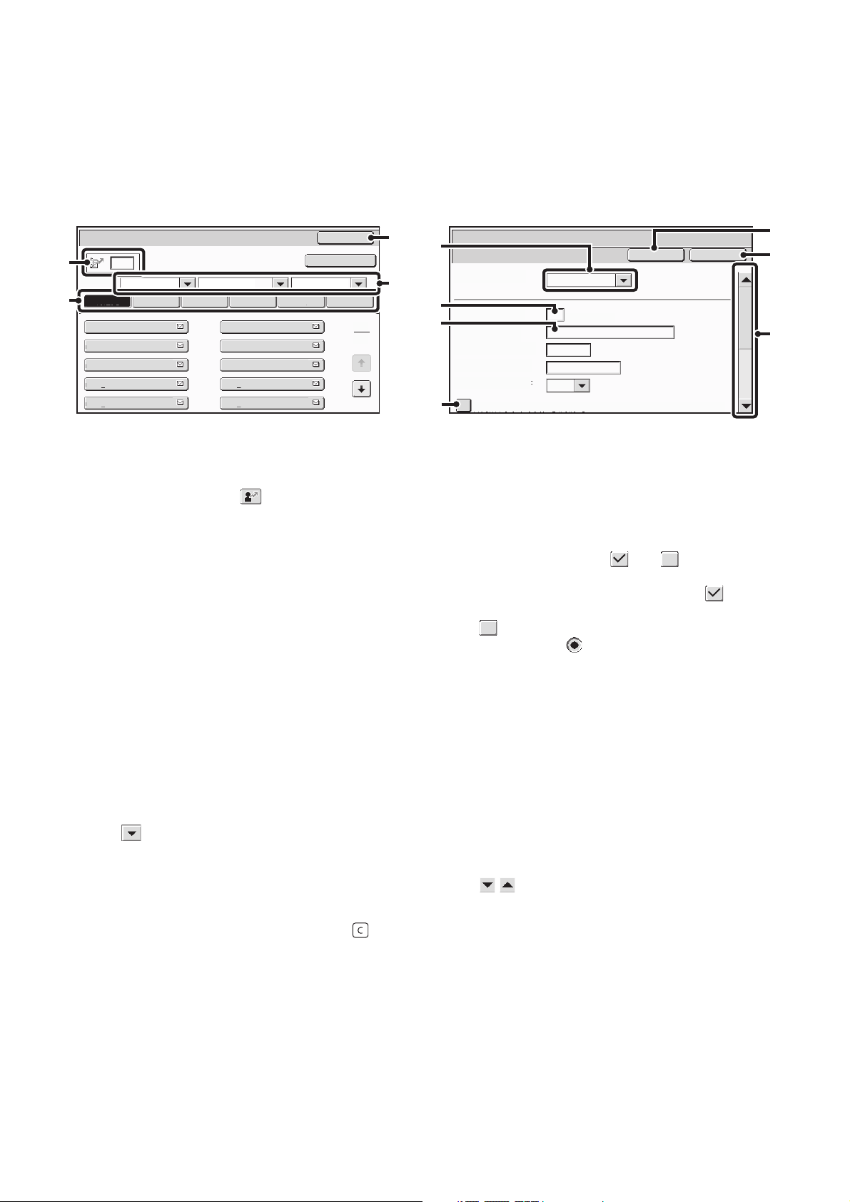
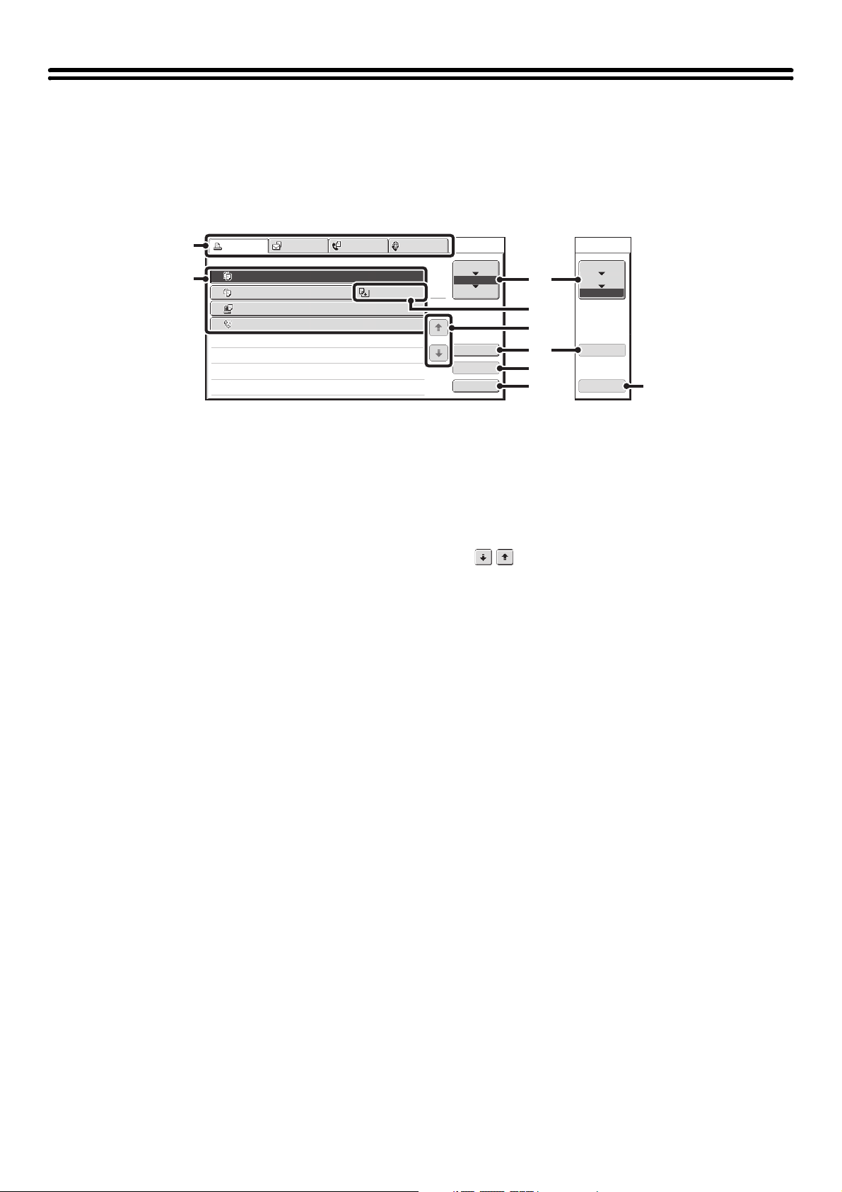
Example: Address book screen
Address Book
(1)
Sort
ABC All UP
(2)
Freq.
AAA AAA
CCC CCC
EEE EEE
GGG GGG
III III
ABCD EFGHI JKLMN OPQRST UVWXYZ
BBB BBB
DDD DDD
FFF FFF
HHH HHH
JJJ JJJ
(1) Search box
Enter a search number in this box to search for the
corresponding address.
When searching for a user, appears in the icon
display.
(2) Index keys
Touch an index key to display the corresponding
addresses. The index keys that appear vary depending
on the "Sort" setting.
(3) [Back] key
Returns you to the previous screen.
(4) "Sort"
Use this to select the method of displaying addresses
and the index type.
Example: In the "Address Book" screen, the display can
be switched between the following three methods:
• Alphabetical / User index
• Display by mode
• Ascending / Descending / Number order
(5) Select box
Touch to display a list of the items that can be
selected. Touch an item in the list to select it.
(6) Text box (numerical)
Touch this box to enter a number. Numbers are entered
with the numeric keys.
If you make a mistake, press the [CLEAR] key ( ) to
clear the incorrect number.
Back
Add
(9)
(10)
(11)
(5)
(6)
(7)
(8)
System Settings
Address Control
Address Type:
Search Number:
Address Name
(Required):
Initial (Optional):
Key Name:
Custom Index:
Register this Address to be added to the [Frequent Use] index.
E-mail
(1-999)
User 1
Cancel
OK
(3)
(4)
1
2
(7) Text box
Touch this box to open a text entry screen. When you
have finished entering text in the text entry screen, the
text will appear in the text box. To enter text, see "7.
ENTERING TEXT" (page 97).
(8) Checkbox
This switches between and each time you touch
it. To enable the corresponding setting, touch the
checkbox so that a checkmark appears . To disable
the setting, touch the checkbox to remove the checkmark
.
Radio buttons ( ) are also used to select settings in
this way. (However, radio buttons are used to select a
single item out of several.)
(9) [Cancel] key
This cancels a setting and returns you to the previous
screen.
(10) [OK] key
Touch this to store the current settings.
(11) Scroll bar
Use this to scroll the screen up and down.
Touch the bar and slide it up or down to move the screen.
You can also move the screen up and down with the
keys.
14
Page 15
SYSTEM BAR
The system bar appears at the bottom of the touch panel.
The items that appear in the system bar are explained below.
Plain
Plain
Auto
8½x11
1.
8½x11
3.
4.
Exposure
Auto
Copy Ratio
100%
Copying
Original Paper Select
11x17
8½x14
2.
8½x11
5.
6.
7.
Auto
8½x11
Plain
11x17
11x17
11x17
Plain
8½x11
Special Modes
2-Sided Copy
Output
File
Quick File
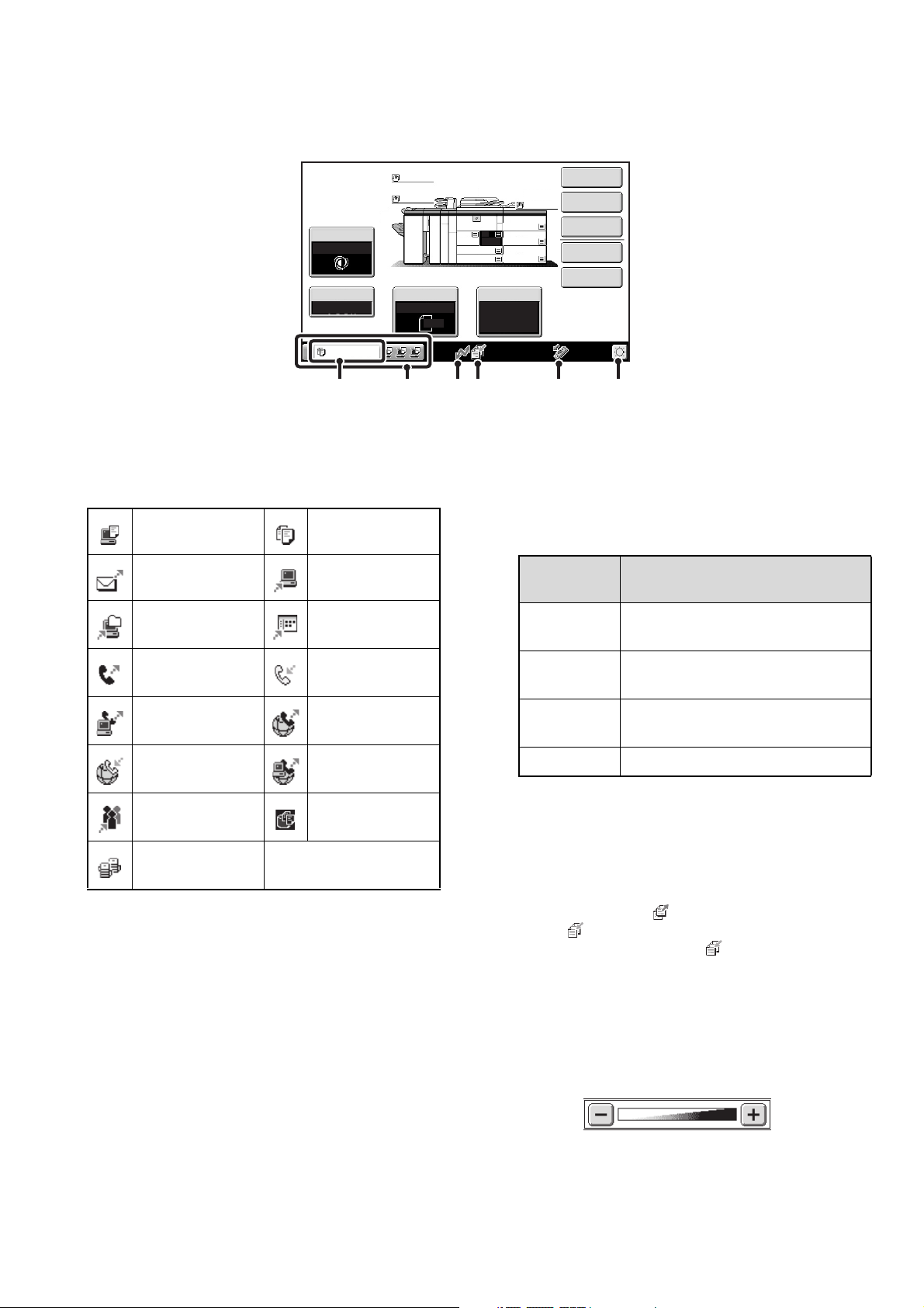
(1) Job status display
The first four jobs in progress or reserved are indicated
by icons.
The icons are as follows.
Print job Copy job
Scan to E-mail job
Scan to Network
Folder job
Fax transmission
Scan to FTP job
Scan to Desktop
job
Fax reception job
job
PC-Fax
transmission job
Internet Fax
reception job
Internet fax
transmission job
PC-I-Fax
transmission job
Broadcast job Scan to HDD file
print job
(1)(A)
(2) (3) (4) (5)
The status of the first job is indicated as shown in (A).
(When a base screen other than that of image send
mode appears, the number of the tray being used to feed
paper appears during paper feeding.) The color
appearing in the job status display depends on the job
status as indicated in the table below. The job status
display can be touched to show the job status screen.
Job status
display
Green
Yellow
Red
Machine Configuration
A print, scan or other job is being
executed normally.
The machine is warming up or on
standby, or a job is being canceled.
A paper misfeed or other error
condition has occurred.
Gray The machine has no jobs.
(2) Line-in-use icon display
This icon appears when data is being sent or received.
Tandem
copy/print job
(3) Data icon display
This icon appears when fax, scan, or Internet fax data is
stored in the machine's memory. When data to be
transmitted is stored, appears. When received data is
stored, appears. When both data to be transmitted
and received data are stored, appears.
(4) USB device display
This icon appears when a USB memory or other USB
device is connected to the machine.
(5) Brightness adjustment key
Touch this key to adjust the brightness of the touch panel.
When touched, the following screen appears next to the key.
Touch the [+] key or the [-] key to adjust the brightness.
When finished, touch the brightness adjustment key
again to close the screen.
15
Page 16
PRINT/SEND STATUS (JOB STATUS)
This screen appears when the [JOB STATUS] key on the operation panel is pressed.
The screen shows lists of the jobs that are reserved and in progress, and jobs that have been completed. This screen is
used to check jobs, move a job to the top of the job queue, or delete a job.
"Complete"
job screen
(1)
(2)
Print Job
Job Queue Sets / Progress Status
Copy
1
Copy
2
Computer01 0002 / 0000
3
0312345678 0001 / 0000
4
Scan to Fax Job Internet Fax
0020 / 0001
0002 / 0000
(1) Mode select tabs
Use these tabs to select print mode, scan mode, fax
mode, or Internet fax mode.
• The [Print Job] tab shows copy, print, received fax,
received Internet fax, and self print jobs.
• The [Scan to] tab shows transmission jobs that use the
scanner function.
• The [Fax Job] tab shows transmission (and reception)
jobs that use the fax and PC-Fax functions.
•
The [Internet Fax] tab shows transmission (and reception)
jobs that use the Internet fax and PC-I-fax functions.
For more information on the job status screen in each
mode, see the manual for each mode.
(2) Job list
• The screen shows lists of the jobs that are reserved
and in progress, and jobs that have been completed.
When the [Print Job] tab is touched in the mode select
tabs, the job status screen selector key changes and
the "Spool" list appears.
A brief description of each job and its status appears in
the list.
• The "Spool" screen shows spooled print jobs and
encrypted PDF jobs waiting for password entry. To
move an encrypted PDF job from the spool list to the
job queue, touch the key of the job and enter the job
password.
(3) Job status screen selector key
This switches the job list display between spooled jobs, the job
queue, and completed jobs.
"Spool": This shows spooled print jobs and encrypted
PDF jobs waiting for password entry. "Spool"
appears when print jobs are displayed.
"Job Queue":This shows reserved jobs and the job in
progress.
"Complete":This shows completed jobs.
(4) "Paper Empty" display
Add paper.
When the status is "Paper Empty", the specified size of
paper for the job is not loaded in any of the trays.
Copying
Paper Empty
Waiting
Waiting
1
1
Spool
Job Queue
Complete
(3)
(4)
Spool
Job Queue
Complete
(5)
Detail
Priority
Stop/Delete
(6)
(7)
(8)
Detail
Call
(9)
In this case, the job will be held until the required size of
paper is loaded. Other jobs that are waiting will be printed (if
possible) ahead of the held job. (However, other jobs will not
be printed if the paper ran out while printing was in progress.)
If you need to change the paper size because the
specified paper size is not available, touch the key of the
job in the job list (2) to select it, touch the [Detail] key
described in (6), and select a different paper size.
(5) keys
These change the page of the displayed job list.
(6) [Detail] key
This shows detailed information on a selected job.
When a job has been stored using Quick File or File in
document filing mode, or when a broadcast transmission
has been performed in image send mode, the job
appears as a key in the completed jobs screen. You can
touch the [Detail] key to show details on the completed
job, and you can also touch the [Call] key to reprint or
resend the job.
(7) [Priority] key
A reserved job in the "Job Queue" screen can be printed
ahead of all other reserved jobs by selecting the job and
then touching this key.
In the print job queue, select the print or copy job to
which you wish to give priority and touch this key. The job
in progress stops and printing of the selected job begins.
When the selected job is completed, the interrupted job
resumes.
(8) [Stop/Delete] key
Use this key to cancel the job currently in progress or a
selected reserved job. Note that printing of received faxes
and received Internet faxes cannot be canceled.
(9) [Call] key
A job that appears in the completed jobs screen as a key
can be touched followed by the [Call] key to reprint or
resend the job. This is the same [Call] key that appears
when the [Detail] key is touched.
16
Page 17
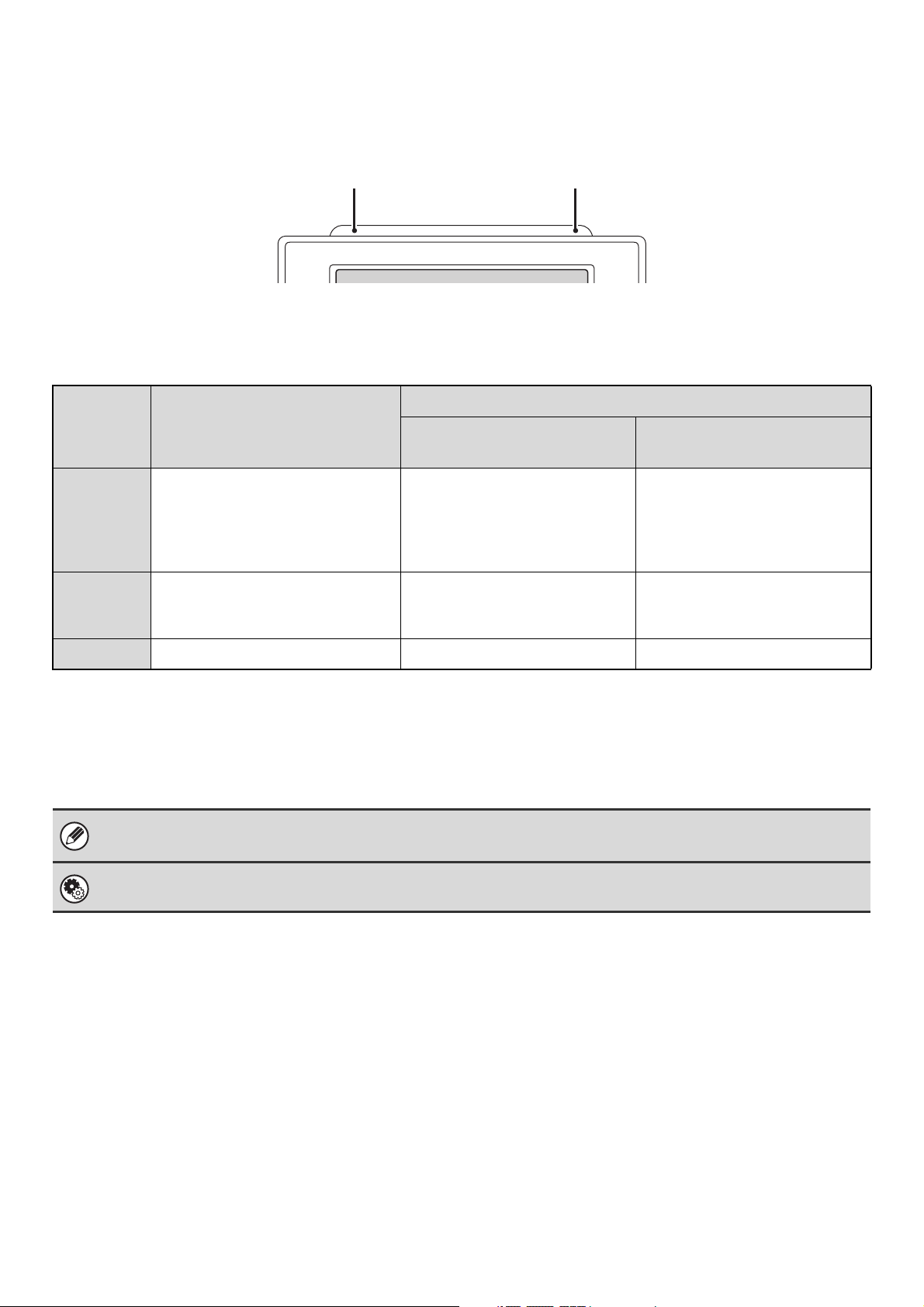
STATUS INDICATORS
There are status indicators at the top of the operation panel.
There are both red and green indicators, and these light or blink to indicate the machine's status.
Red indicatorGreen indicator
About status indicator lighting and blinking
The status indicators light or blink to indicate the following conditions.
Green indicator
Red indicator
Pattern 1
(Job status display)
(Machine status display)
Pattern 2
A problem exists but the machine
Lights
solidly
Blinking
Off
The green indicator has two indicating patterns. The indicating pattern can be changed using "Status Indicator Settings"
in the system settings (administrator). The factory default setting is "Pattern 1".
• If solidly lit and blinking states occur simultaneously, the blinking state is given priority.
• When auto power shut-off has occurred, the status indicators turn off.
System Settings (Administrator): Status Indicator Settings
Use this to change the indicator settings of the green status indicator.
can be used.
(The toner cartridge is out of toner
and the machine is using the spare
toner, etc.)
A problem exists that prevents the
machine from being used (out of
toner, paper misfeed, etc.)
No problems Standby Jobs cannot be accepted
Job in progress
(During paper feeding and
output.)
Original scanning in progress Job in progress
Standby
(During original scanning, paper
feeding, and output)
17
Page 18

TURNING THE POWER ON AND OFF
The machine has two power switches. The main power switch is at the lower left after the front cover is opened. The
other power switch is the [POWER] key ( ) on the operation panel at the top right.
Main power switch
When the main power switch is switched on, the main
power indicator on the operation panel lights up.
"On" position
"Off" position
Turning on the power
(1) Switch the main power switch to the "on"
position.
(2) Hold down the [POWER] key ( ) until the
touch panel turns on.
The machine power turns on.
[POWER] key
Main power indicator
PROOF COPY
[POWER] key
Turning off the power
(1) Hold down the [POWER] key ( ) until the
touch panel turns off.
(2) Switch the main power switch to the "off"
position.
• Before turning off the main power switch, make sure that a job is not in progress or being processed.
Switching off the main power switch or removing the power cord from the outlet while a job is in progress or being
processed may damage the hard drive and cause data to be lost.
• Switch off both the [POWER] key ( ) and the main power switch and unplug the power cord if you suspect a machine
failure, if there is a bad thunderstorm nearby, or when you are moving the machine.
When using the fax or Internet fax function, always keep the main power switch in the "on" position.
Main power indicator
The main power indicator may light green or orange, depending on the machine's status.
What the main power indicator
indicates
Green The main power switch is turned on
Orange The fax or Internet fax function can be used on the machine and the power has been
turned off with the [POWER] key ( ) with the main power switch still switched on.
Off The main power switch is switched off
Machine Configuration
18
Page 19
ENERGY SAVE FUNCTIONS
This product has the following two energy save functions that conform to the Energy Star guidelines to help conserve
natural resources and reduce environmental pollution.
Preheat Mode (low power mode)
Preheat mode automatically lowers the temperature of the fusing unit and thereby reduces power consumption if the
machine remains in the standby state for the interval of time set in "Preheat Mode Setting" in the system settings
(administrator). This keeps the fusing unit at a lower temperature and reduces power consumption while the machine is
on standby.
The machine automatically wakes up and returns to normal operation when a print job is received, a key is pressed on the
operation panel, or an original is placed.
Auto power shut-off mode (Sleep mode)
Auto power shut-off mode automatically shuts off power to the display and the fusing unit if the machine remains in the
standby state for the interval of time set in "Auto Power Shut-Off Timer" in the system settings (administrator). This
mode provides the lowest level of power consumption. Considerably more power is saved than in preheat mode,
however, the wakeup time is longer. This mode can be disabled in the system settings (administrator).
The machine automatically wakes up and resumes normal operation when a print job is received or when the blinking
[POWER SAVE] key ( ) is pressed.
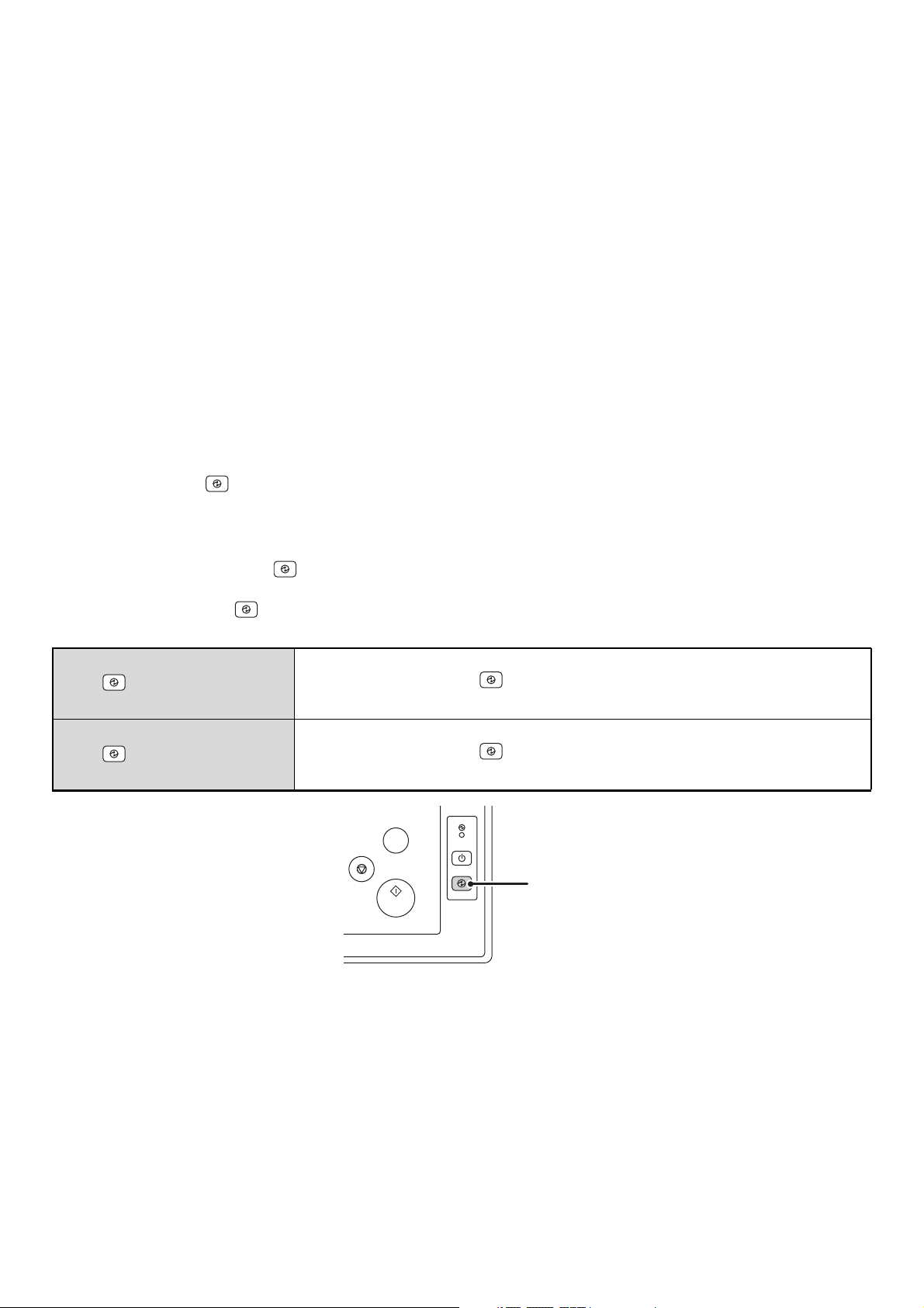
[POWER SAVE] KEY
Press the [POWER SAVE] key
shut-off mode.
The [POWER SAVE] key
mode.
When the [POWER SAVE]
key ( ) indicator is off in
the standby state
When the [POWER SAVE]
key ( ) indicator is
blinking
()
()
to put the machine in auto power shut-off mode or wake it up from auto power
has an indicator that indicates whether or not the machine is in auto power shut-off
The machine is ready to be used.
If the [POWER SAVE] key ( ) is pressed when the indicator is off, the indicator will
blink and the machine will enter auto power shut-off mode after a brief interval.
The machine is in auto power shut-off mode.
If the [POWER SAVE] key ( ) is pressed when the indicator is blinking, the indicator
will turn off and the machine will return to the ready state after a brief interval.
PROOF COPY
[POWER SAVE] key / indicator
19
Page 20
USER AUTHENTICATION
User authentication restricts the use of the machine to users that have been registered. The functions that each user is
allowed to use can be specified, allowing the machine to be customized to meet the needs of your workplace.
When the administrator of the machine has enabled user authentication, each user must log in to use the machine. The
are different types of user authentication, and each type has a different login method.
For more information, see the explanations of the login methods.
• AUTHENTICATION BY USER NUMBER (see below)
• AUTHENTICATION BY LOGIN NAME / PASSWORD (page 22)
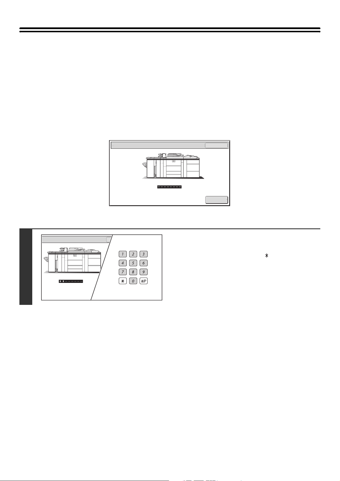
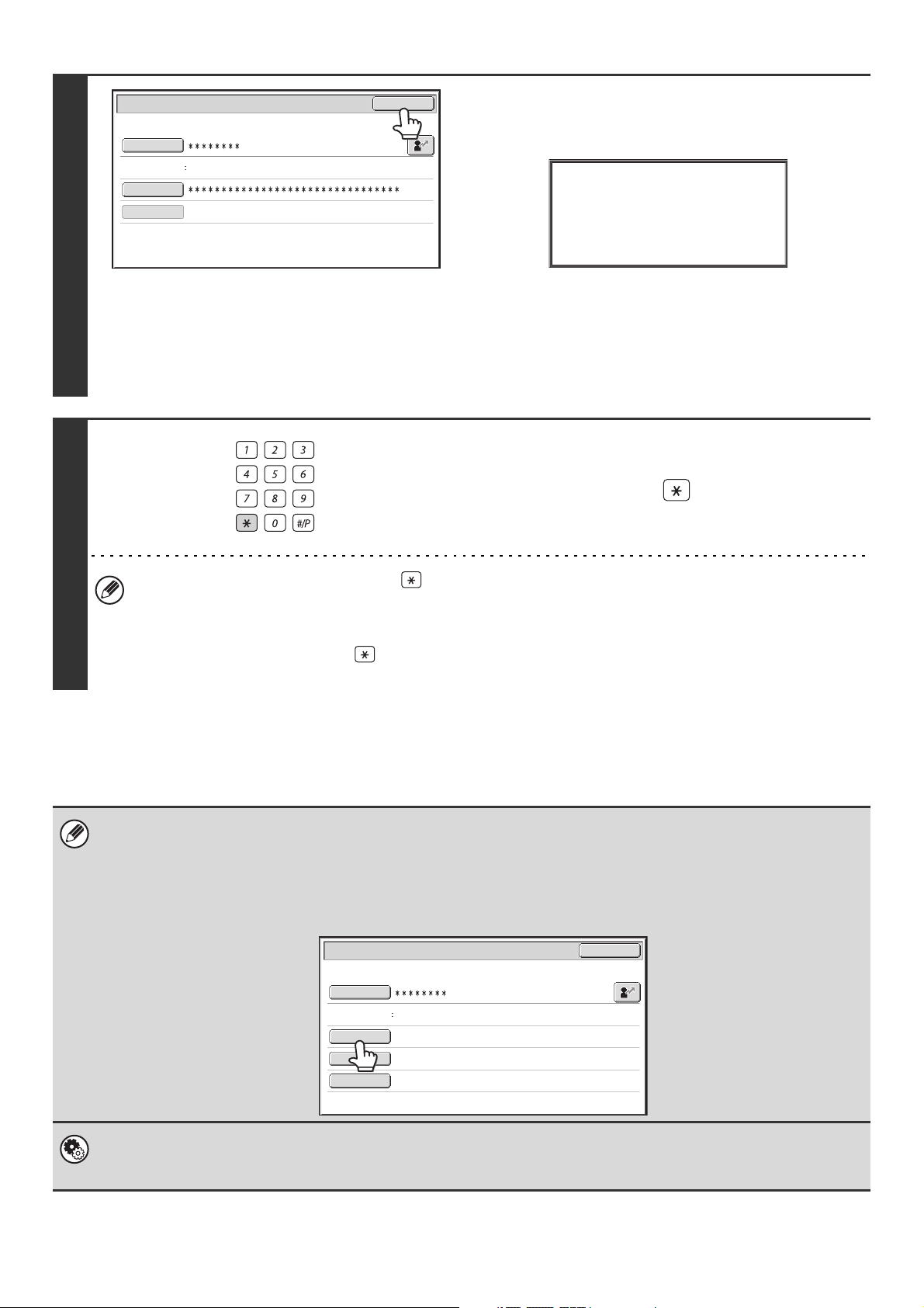
AUTHENTICATION BY USER NUMBER
The following procedure is used to log in using a user number received from the administrator of the machine.
1
User Authentication
When controlled by user number
Enter your user number (5 to 8 digits)
with the numeric keys.
Each entered digit will be displayed as " ".
OK
Admin Login
20
Page 21
User Authentication
OK
Admin Login
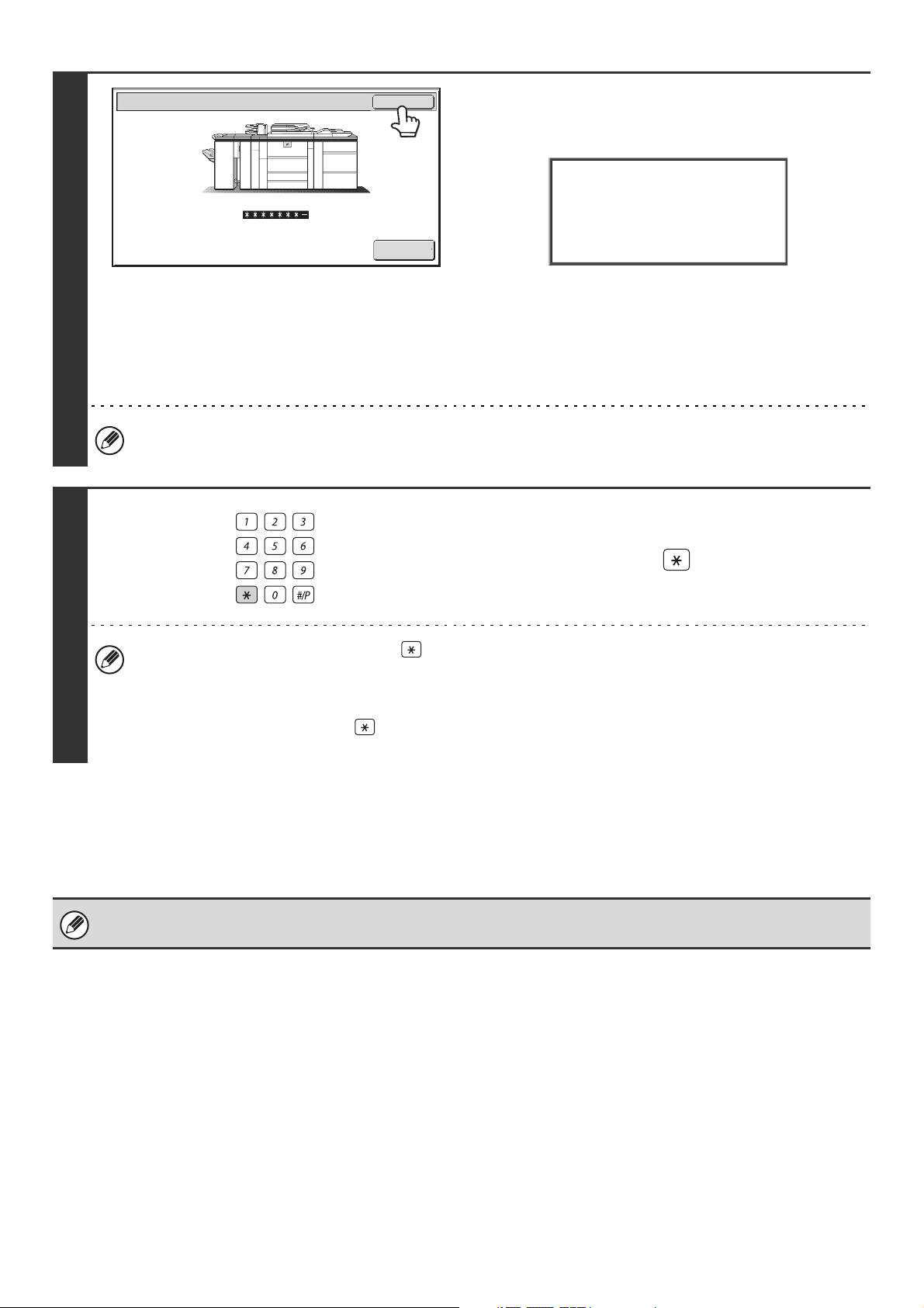
Touch the [OK] key.
After the entered user number is authenticated, the user count
screen will appear briefly.
Usage
status: used/remaining pages
Black-white : 87,654,321/12,345,678
Full color : 87,654,321/12,345,678
2-color : 87,654,321/12,345,678
Single color: 87,654,321/12,345,678
2
3
When page limits have been set in "Pages Limit Group List" in
the system settings (administrator), the number of pages
remaining will appear. (The remaining number of pages that the
user can use in each mode (copy, scan, etc.) appears.) The
amount of time that this screen appears can be changed using
"Message Time Setting" in the system settings (administrator).
When the user number is an 8-digit number, this step is not necessary. (Login takes place automatically after the user
number is entered.)
When you have finished using the
machine and are ready to log out, press
the [LOGOUT] key ( ).
LOGOUT
• However, note that the [LOGOUT] key ( ) cannot be used to log out when a fax number is being entered in fax
mode, as the key is used for fax number entry.
• If a preset duration of time elapses after the machine is last used, the Auto Clear function will activate. When Auto
Clear activates, logout takes place automatically. However, when PC Scan mode is used, logout does not take
place when the [LOGOUT] key ( ) is pressed and Auto Clear does not operate. Change to a different mode on
the machine and then log out.
If an incorrect user number is entered 3 times in a row...
If "A Warning when Login Fails" is enabled in the system settings (administrator), the machine will lock for 5 minutes if
an incorrect user number is entered 3 times in a row.
Verify the user number that you should use with the administrator of the machine.
The administrator can clear the locked state.
This is done from [User Control] and then [Other Settings] in the Web page menu.
21
Page 22
AUTHENTICATION BY LOGIN NAME / PASSWORD
The following procedure is used to log in using a login name and password received from the administrator of the
machine or the administrator of the LDAP server.
1
User Authentication
Login Name
User Name
Password
Auth to:
Login Locally
User Authentication
Login Name
User Name
Password
Auth to:
Login Locally
OK
When controlled by login name and password
(Different items will appear in the screen when LDAP authentication is used.)
OK
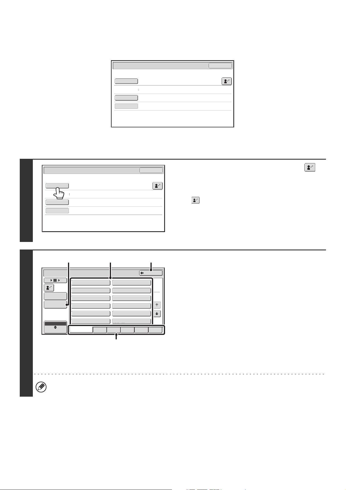
Touch the [Login Name] key or the
key.
If the [Login Name] key is touched, a screen for selecting the
user name appears. Go to the next step.
If the key is touched, an area for entering a "Registration
No." appears [---].
Use the numeric keys to enter your registration number that
has been stored in "User List" in the system settings
(administrator). After entering the registration number, go to
step 3.
2
(A)
Device Account Mode User Selection
12 186
Admin Login
Direct Entry
ABC
User
User 0001
User 0003
User 0005
User 0007
User 0009
User 0011
All Users ABCD EFGHI JKLMN OPQRST UVWXYZ
(B) (C)
Back
User 0002
User 0004
User 0006
User 0008
User 0010
User 0012
Select the user name.
(A) [Direct Entry] key
Use this key if you have not been stored in "User List" in
the system settings (administrator) and are only using
1
2
LDAP authentication.
A text entry screen will appear. Enter your login name.
To enter text, see "7. ENTERING TEXT" (page 97).
(B) User selection keys
Touch your user name that has been stored in "User List"
in the system settings (administrator).
(C) [Back] key
Touch this key to return to the login screen.
(D)
(D) Index tabs
All users appear on the [All Users] tab. Users are grouped
on the other tabs according to the search characters
entered when each user was stored.
LDAP authentication can be used when the administrator of the server provides LDAP service on the LAN (local area
network).
22
Page 23
3
User Authentication
OK
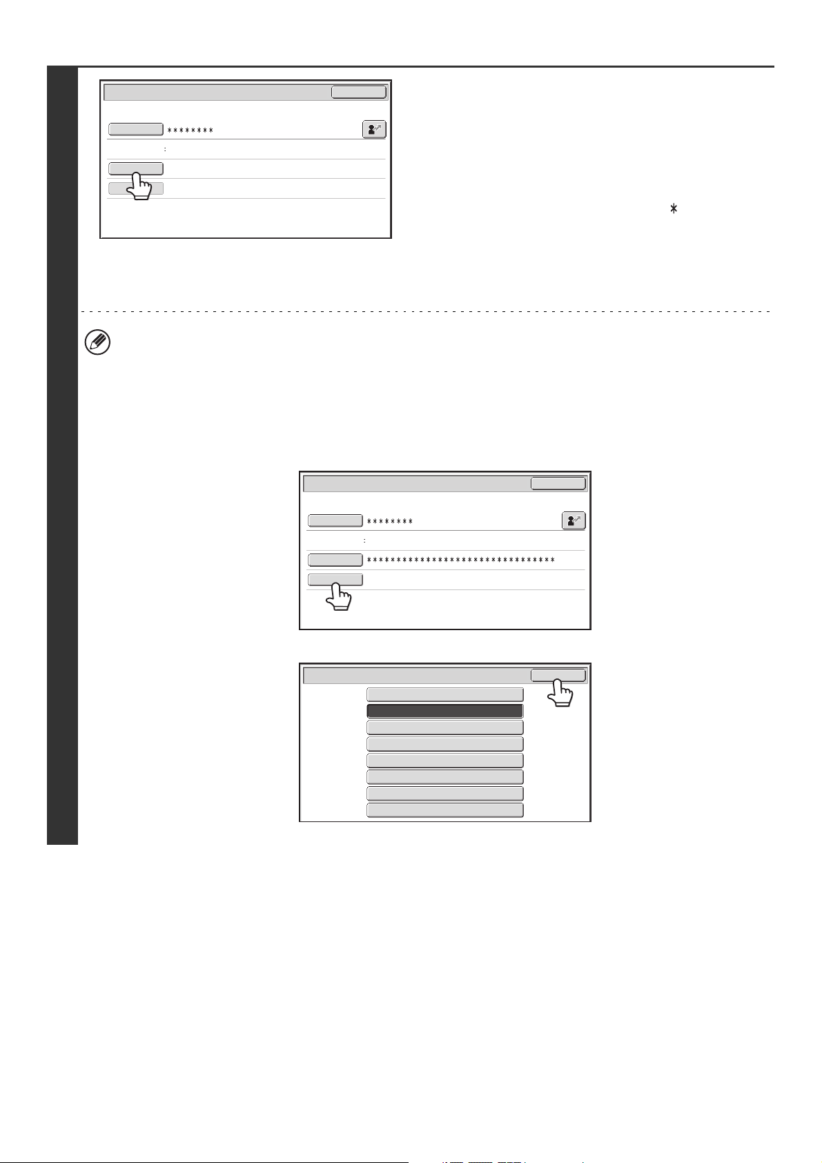
Touch the [Password] key.
A text entry screen for entering the password will appear.
Login Name
User Name
Password
Auth to:
User 0001
Login Locally
Enter your password that is stored in "User List" in the system
settings (administrator).
If you are logging in to an LDAP server, enter the password that
is stored with your LDAP server login name.
Each entered character will be displayed as " ". When you
have finished entering the password, touch the [OK] key.
When authentication is by LDAP server and you have different
passwords stored in "User List" in the system settings
(administrator) and in the LDAP server, use the password
stored in the LDAP server.
• When an LDAP server has been stored, [Auth to:] can be changed.
• If you are logging in using a user selection key...
The LDAP server was stored when your user information was stored, and thus the LDAP server will appear as the
authentication server when you select your login name. Go to step 4.
• When logging in using the [Direct Entry] key...
Touch the [Auth to:] key.
User Authentication
OK
Login Name
User Name
Password
Auth to:
Direct Entry
Login Locally
Select the LDAP server and touch the [OK] key.
Authenticate to:
Login Locally
Server 1
Server 2
Server 3
Server 4
Server 5
Server 6
Server 7
OK
23
Page 24
4
User Authentication
Login Name
User Name
Password
Auth to:
User 0001
Login Locally
OK
Touch the [OK] key.
After the entered login name and password are authenticated,
the user count screen will appear briefly.
Usage
status: used/remaining pages
Black-white : 87,654,321/12,345,678
Full color : 87,654,321/12,345,678
2-color : 87,654,321/12,345,678
Single color: 87,654,321/12,345,678
(Different items will appear in the screen when LDAP
authentication is used.)
When page limits have been set in "Pages Limit Group List" in
the system settings (administrator), the number of pages
remaining will appear. (The remaining number of pages that the
user can use in each mode (copy, scan, etc.) appears.) The
amount of time that this screen appears can be changed using
"Message Time Setting" in the system settings (administrator).
When you have finished using the
machine and are ready to log out, press
the [LOGOUT] key ( ).
LOGOUT
5
• However, note that the [LOGOUT] key ( ) cannot be used to log out when a fax number is being entered in fax
mode, as the key is used for fax number entry.
• If a preset duration of time elapses after the machine is last used, the Auto Clear function will activate. When Auto
Clear activates, logout takes place automatically. However, when PC Scan mode is used, logout does not take
place when the [LOGOUT] key ( ) is pressed and Auto Clear does not operate. Change to a different mode on
the machine and then log out.
If an incorrect login name or password is entered 3 times in a row...
If "A Warning when Login Fails" is enabled in the system settings (administrator), the machine will lock for 5 minutes if
an incorrect login name or password is entered 3 times in a row.
Verify the login name and password that you should use with the administrator of the machine.
• The administrator can clear the locked state.
This is done from [User Control] and then [Other Settings] in the Web page menu.
• When LDAP authentication is used, the [E-mail Address] key may appear, depending on the authentication method. If the
[E-mail Address] key appears in step 3, touch the key.
A text entry screen will appear. Enter your e-mail address. To enter text, see "7. ENTERING TEXT" (page 97).
User Authentication
Login Name
User Name
E-mail Address
Password
Auth to:
User 0002
Server 2
OK
System Settings (Administrator): User Registration
This is used to store names of users of the machine. Detailed information such as the login name, user number, and
password are also stored. Ask the administrator of the machine for the information that you need to use the machine.
24
Page 25
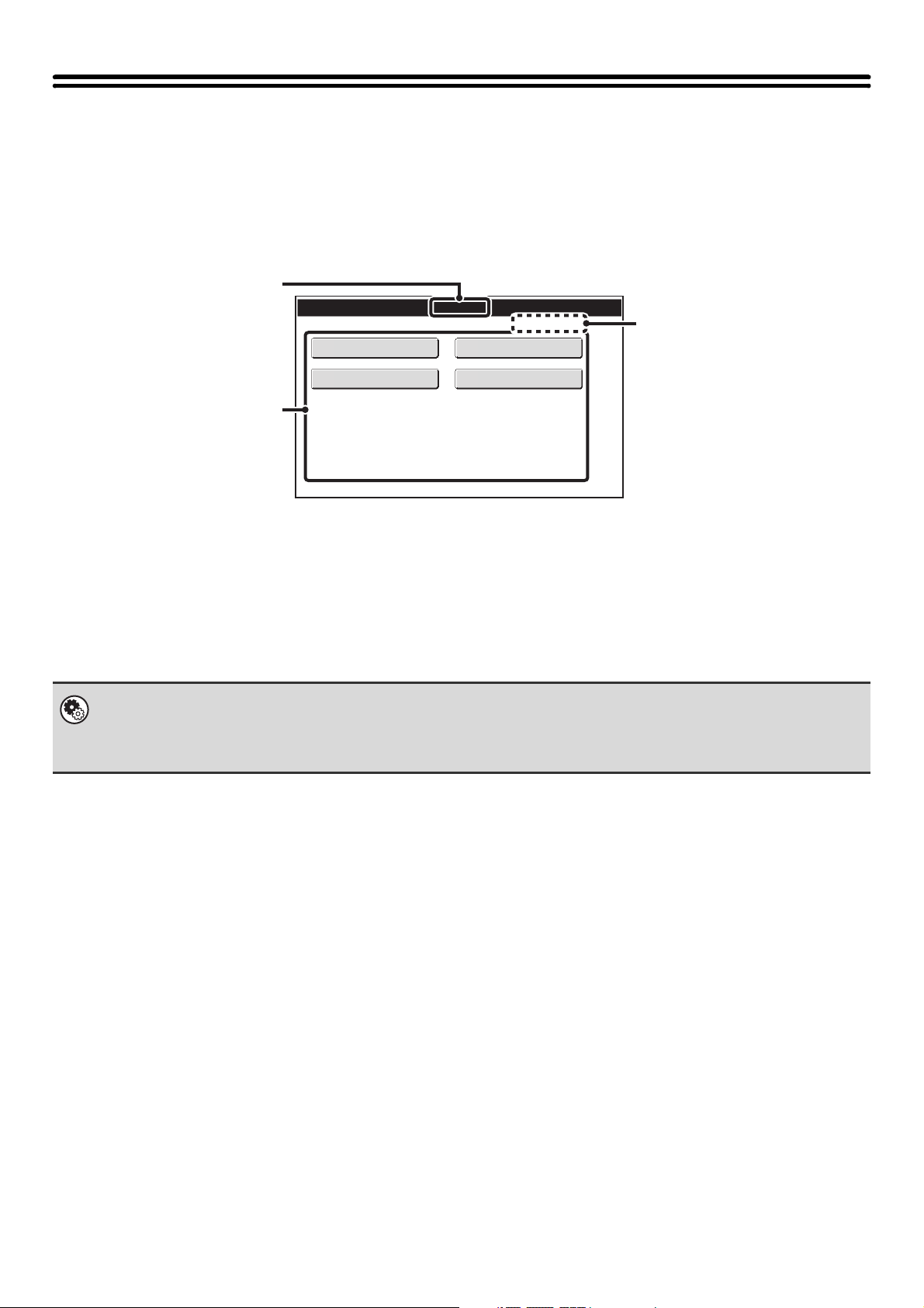
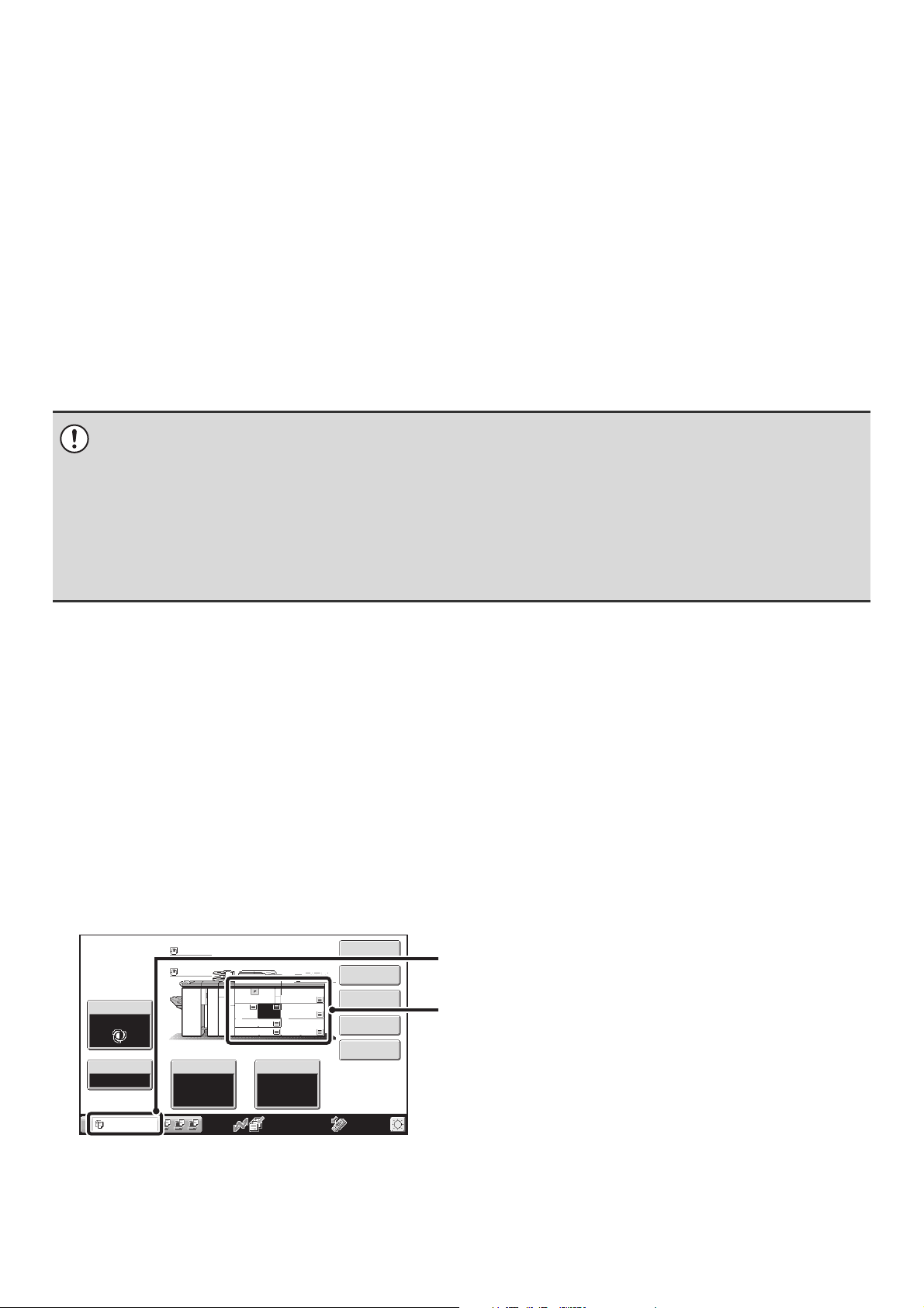
HOME SCREEN
When the [HOME] key is pressed on the operation panel, the home screen appears in the touch panel.
Shortcuts to functions can be registered as keys in the home screen. When a shortcut key is touched, the screen for that
function appears. Register frequently used functions in the home screen to quickly and conveniently access those
functions. When user authentication is used, the home screen of "Favorite Operation Group" can be displayed.
Register keys that you wish to show in the home screen in the Web pages.
(1)
Home Screen
(3)
Total Count
Address Control
Document Filing
Control
(2)
(1) Title
This shows the title of the home screen.
(2) Shortcut key
A registered function appears as a shortcut key.
The key can be touched to select the registered function.
• System Settings (Administrator): Home Screen Settings
Registration is performed in [System Settings] - [Operation Settings] - [Home Screen Settings] in the Web page menu.
• System Settings (Administrator): Home Screen List
Registration is performed in "Home Screen List" in [User Control] in the Web page menu.
Paper Tray Settings
04/04/2010 11:40
(3) User name
This shows the name of the logged in user.
The user name appears when user authentication is
enabled on the machine.
25
Page 26
LOADING PAPER
2
IMPORTANT POINTS ABOUT PAPER
This section provides information that you should know before loading paper in the paper trays.
Be sure to read this section before loading paper.
NAMES AND LOCATIONS OF TRAYS
The trays are identified by the names indicated below. For the names of the peripheral device trays, see "TRAY
LOCATIONS AND NAMES" (page 35). For detailed information on the sizes and types of paper that can be loaded in
each tray of the machine, see the specifications in the Safety Guide and "PAPER TRAY SETTINGS" (page 80) in the
System Settings. For information on the peripheral device trays, see "TRAY LOCATIONS AND NAMES" (page 35).
Tray 1
Tray 2
Tray 3
Tray 4
THE MEANING OF "R" IN PAPER SIZES
Some original and paper sizes can be placed in either the vertical or the horizontal orientation. To differentiate between
vertical and horizontal orientations, paper sizes in the horizontal orientation will be followed by an "R" (for example,
8-1/2" x 11"R, A4R).
Sizes that can be placed only in the horizontal orientation (12" x 18", 11" x 17", 8-1/2" x 14", 8-1/2" x 13", A3W, A3, B4)
do not include the "R" in their size indication.
8-1/2" x 11"R
(A4R)
Horizontal orientation
"R" is appended.
8-1/2" x 11"
(A4)
Vertical orientation
"R" is not appended.
11" x 17"
(A3)
Can be placed only in the
horizontal orientation
"R" is not appended.
26
Page 27
USEABLE PAPER
Various types of paper are sold. This section explains what plain paper and what special media can be used with the
machine. For detailed information on the sizes and types of paper that can be loaded in each tray of the machine, see
the specifications in the Safety Guide and "PAPER TRAY SETTINGS" (page 80) in the System Settings. For information
on the peripheral device trays, see "TRAY LOCATIONS AND NAMES" (page 35).
Plain paper, special media
Plain paper that can be used
• SHARP standard plain paper (21 lbs. (64 g/m2)). For paper specifications, see the specifications in the Safety Guide.
• Plain paper other than SHARP standard paper (16 lbs. to 28 lbs. (60 g/m
Recycled paper, colored paper and pre-punched paper must meet the same specifications as plain paper. Contact your
dealer or nearest SHARP Service Department for advice on using these types of paper.
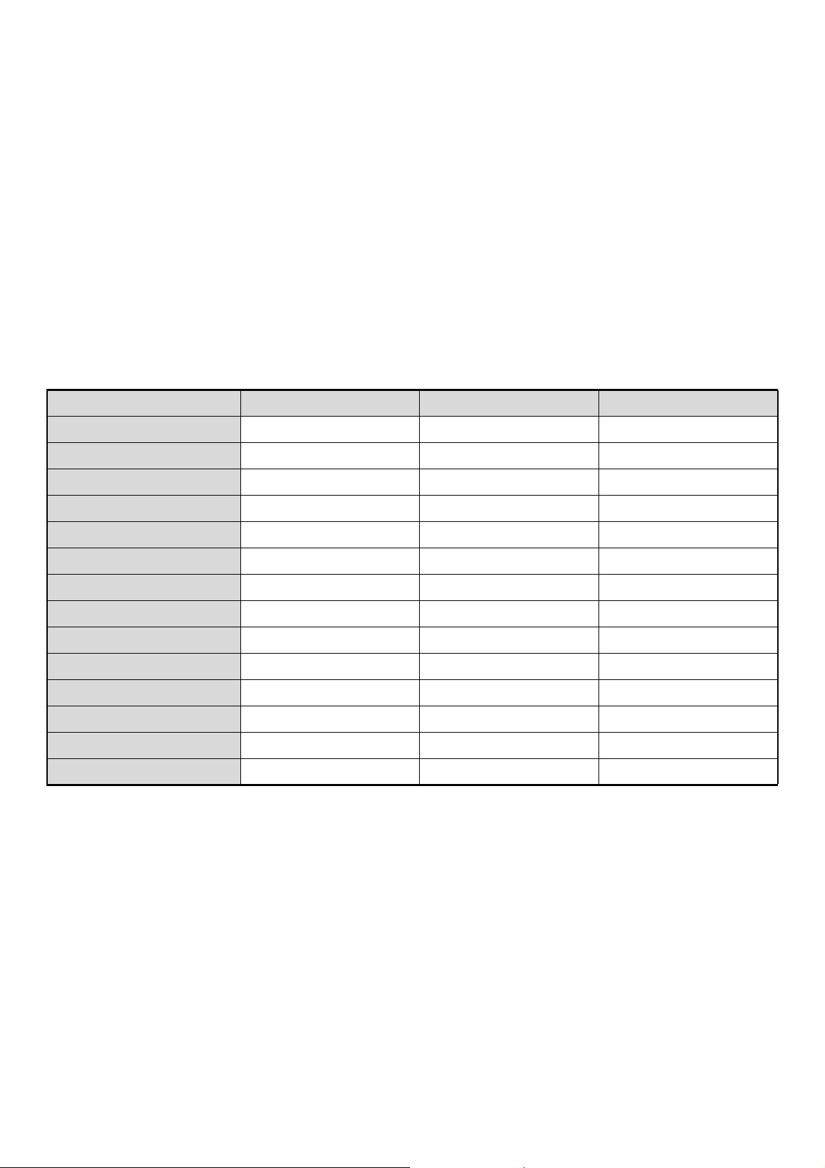
Types of paper that can be used in each tray
The following types of paper can be loaded in each tray. "{" indicates paper that can be used. "X" indicates paper that
cannot be used.
Tray 1/Tray 2 Tray 3 Tray 4
Plain paper { { {
Recycle Paper { { {
Color { { {
2
to 105 g/m2))
Pre-printed { { {
Letter head { { {
Pre-Punched { { {
Heavy paper 1* X { {
Heavy paper 2* X { {
Heavy paper 3* X { {
Heavy paper 4* X X X
Labels X X {
Transparency film
Tab paper X X {
Thin paper X X X
* "Heavy Paper 1" is paper up to 32 lbs. (128 g/m
paper up to 110 lbs.index (205
2
g/m
), and "Heavy Paper 4" is paper up to -100 lbs.cover (300 g/m2).
X X {
2
), "Heavy Paper 2" is paper up to -65 lbs.cover (176 g/m
2
), "Heavy Paper 3" is
Print side face down
Load the paper with the print side face down.
27
Page 28
Paper that cannot be used
• Special media for inkjet printers
(fine paper, glossy paper, glossy film, etc.)
• Carbon paper or thermal paper
• Pasted paper
• Paper with clips
• Paper with fold marks
• Torn paper
• Oil-feed transparency film
Non-recommended paper
• Thin paper less than 13 lbs. (52 g/m
• Paper heavier than 301 g/m
2
.
2
)
• Irregularly shaped paper
• Stapled paper
• Damp paper
• Curled paper
• Paper with a wave-like pattern due to moisture
absorption
• Iron-on transfer paper
• Japanese paper
• Reverse side of paper already printed on by another
printer or copier.
• Perforated paper
• Various types of plain paper and special media are sold. Some types cannot be used with the machine. Contact your
dealer or nearest SHARP Service Department for advice on using these types of paper.
• The image quality and toner fusibility of paper may change due to ambient conditions, operating conditions, and paper
characteristics, resulting in image quality inferior to that of SHARP standard paper. Contact your dealer or nearest SHARP
Service Department for advice on using these types of paper.
• The use of non-recommended or prohibited paper may result in skewed feeding, misfeeds, poor toner fusing (the toner
does not adhere to the paper well and can be rubbed off), or machine failure.
• The use of non-recommended paper may result in misfeeds or poor image quality. Before using non-recommended paper,
check if printing can be performed properly.
Tray during paper feeding
Do not pull out a tray while paper is being fed from the tray. This will cause a paper misfeed.
Tray 1 and tray 2 are joined together, so do not pull out the trays while paper is feeding from either tray.
Identifying the tray that is being used to feed paper
(1) While paper is feeding, the job status display of the system bar on the touch panel screen will show the number of
the tray that is being used to feed paper. However, this will not appear when the base screen of image send mode
appears. To show the tray number in this case, change to the base screen of a different mode, or change to the job
status screen (page 16) and select the [Print Job] tab in the mode select tabs.
(2) During output in copy mode, the tray being used to feed paper also appears in green in the paper size display in the
base screen of copy mode on the touch panel.
Example: Base screen of copy mode
Plain
Exposure
Auto
Copy Ratio
100%
Tray2
Plain
2.
1.
8½x11
8½x11
3.
11x17
8½x14
4.
Original Paper Select
Auto
8½x11
5.
6.
7.
Auto
8½x11
Plain
11x17
11x17
11x17
Plain
8½x11
Special Modes
2-Sided Copy
Output
File
Quick File
(1) Job status display on the system bar
Shows the number of the tray being used to feed paper.
(2) Paper size display
Shows the tray being used to feed paper in green.
28
Page 29
TRAY SETTINGS FOR TRAY 1 AND TRAY 2
LOADING PAPER
Up to 1200 sheets of 8-1/2" x 11" or A4 size paper can be loaded in tray 1. Up to 800 sheets of 8-1/2" x 11" or A4 size
paper can be loaded in tray 2.
For detailed information on the paper that can be loaded, see the specifications in the Safety Guide and "PAPER TRAY
SETTINGS" (page 80) in the System Settings.
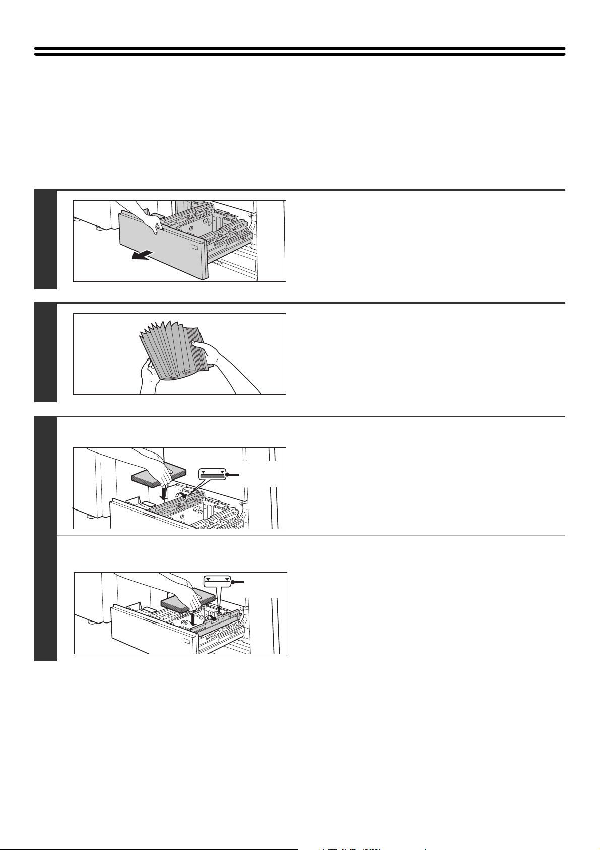
Pull out tray 1 - tray 2.
Gently pull the tray out until it stops.
1
Fan the paper.
Fan the paper well before loading it. If the paper is not fanned,
multiple sheets may feed at once and cause a misfeed.
2
3
● Tray 1
● Tray 2
Indicator
line
Indicator
line
Load paper in the left and right trays.
Raise the paper guide and load the paper with the print side
face down.
(maximum of 1200 sheets).
Raise the paper guide and load the paper with the print side
face down. The stack must not be higher than the indicator line
(maximum of 800 sheets).
Be sure to return the paper guide to its original position after
loading the paper.
The stack must not be higher than the indicator line
29
Page 30
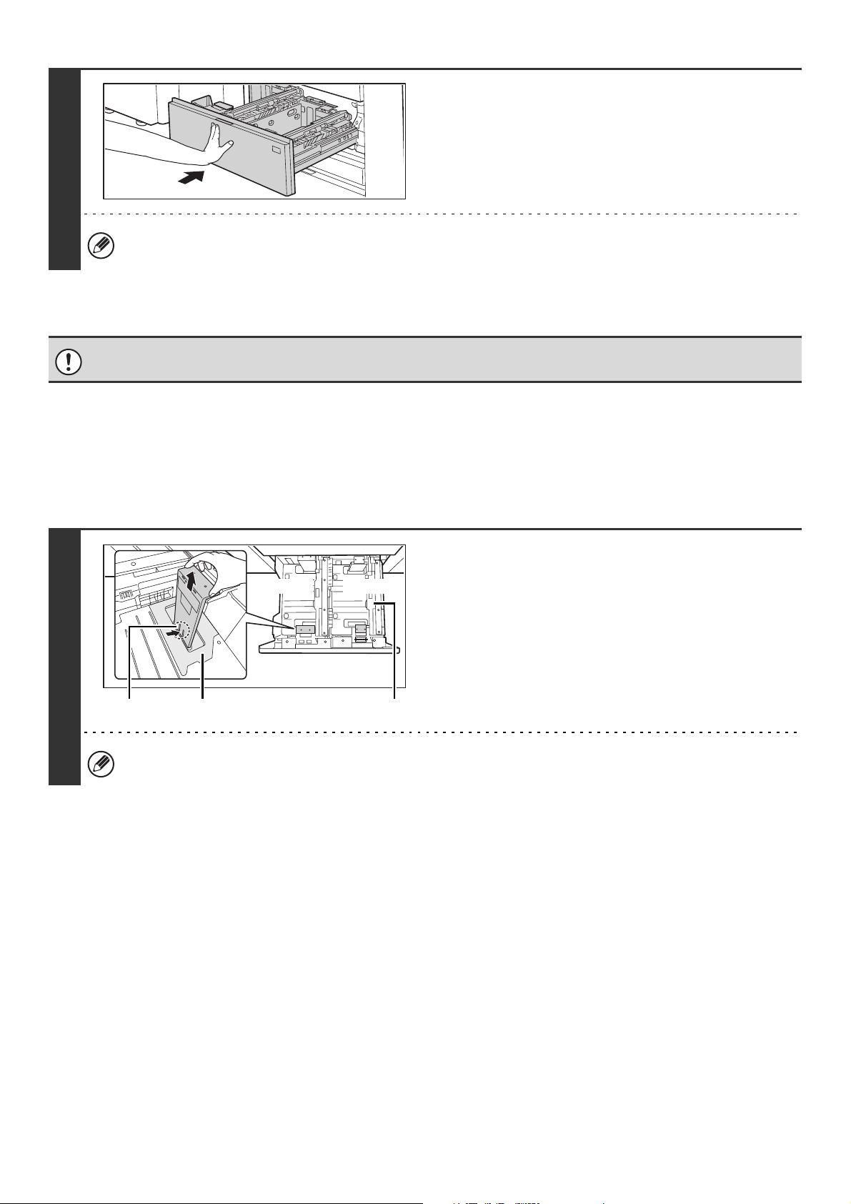
Gently push tray 1- tray 2 into the
machine.
Push the tray firmly all the way into the machine.
4
If you loaded a different type of paper than was loaded previously, change the paper type setting as explained in
"PAPER TRAY SETTINGS" (page 80) in the System Settings.
Do not place heavy objects on the tray or press down on the tray.
CHANGING THE PAPER SIZE
To change the paper size of tray 1 - tray 2, follow the steps below.
This section only explains how to change the paper size. For the procedures for opening/closing the tray and loading
paper, see "LOADING PAPER" (page 29).
1
Remove the paper size guide.
Tray 1 Tray 2
Hook Transparent sheet
Before changing the paper size of tray 2, raise the paper guide.
Paper guide
With the base of the tray pressed all the way down, hold down
the hook at the bottom on the paper size guide and pull the
paper size guide up slightly.
30
Page 31

2
(1)
LT
A4
Transparent sheet
When attaching the paper size guide, make sure that the top and bottom of the guide are aligned to the same paper size. If the top
and bottom of the paper size guide are not aligned to the same paper size, skewed feeding and misfeeds will result.
(2)
A4
LT
transparent sheet appropriately for the
size of paper to be used.
(1)
Align the bottom of the paper size guide with
the appropriate slot on the base of the tray.
Align the paper size guide with the slot for the paper size
to be used (indicated by the paper size mark).
(2) Align the holes at the top of the paper size
guide with the protrusions that secure the
paper size guide.
Align with the holes for the paper size to be used
(indicated by the paper size mark).
(3) Push in the paper guide so that it locks into
place.
Push the paper size guide in until the hook at the bottom
locks into place. (You will hear a "click" when the hook
locks.) Move the paper size guide slightly to verify that it
has locked into place.
Attach the paper size guide and
3
• When attaching the paper size guide, place the transparent sheet in direct contact with the base of the tray in the
correct orientation as shown.
• The slot or hole with the "LT" mark is for 8-1/2" x 11" size.
Repeat steps 1 and 2 to adjust the far
paper guide to the paper size to be used.
Be sure to adjust the far paper guide to the same size as the
near paper guide.
Transparent sheet
Adjusting only one paper guide may result in skewed feeding or misfeeds.
When removing and attaching the far paper size guide, take
care not to hit the front cover of the machine.
Set the paper size and paper type.
Be sure to change the paper size and paper type settings as explained in "PAPER TRAY SETTINGS" (page 80) in the
System Settings.
4
If the paper size setting is not configured correctly, automatic paper selection will not operate correctly and printing may take
place on the wrong size or type of paper or a misfeed may occur.
Do not place heavy objects on the tray or press down on the tray.
31
Page 32

TRAY SETTINGS FOR TRAY 3 AND TRAY 4
LOADING PAPER AND CHANGING THE PAPER SIZE
Up to 500 sheets of 7-1/4" x 10-1/2"R to 12" x 18" size paper (B5R to A3W size paper) can be loaded in tray 3. Up to 500
sheets of 5-1/2"x 8-1/2"R to 12"x 18" size paper (A5R to A3 size paper) can be loaded in tray 4.
For detailed information on the paper that can be loaded, see the specifications in the Safety Guide and "PAPER TRAY
SETTINGS" (page 80) in the System Settings.
Pull out the paper tray.
Gently pull the tray out until it stops.
If you are simply adding paper, go to step 3. To load a different
1
A
size of paper, go to the next step.
Adjust the guide plates A and B by
squeezing their lock levers and sliding
them to match the vertical and horizontal
dimensions of the paper to be loaded.
2
3
(1) Squeeze the lock knob on guide plate A and
B
C
A non-standard size of paper can only be loaded in tray 4. A non-standard size of paper cannot be loaded in tray 3.
slide to the desired paper size.
(2) Squeeze the lock knob on guide plate B and
slide to the desired paper size.
If slid to a standard paper size, guide plate B will lock
automatically.
(3) For a non-standard paper size, after sliding
guide plate B to the desired size, press the
lock button (C).
Fan the paper.
Fan the paper well before loading it. If the paper is not fanned,
multiple sheets may feed at once and cause a misfeed.
32
Page 33

4
5
Insert the paper into the tray.
Load the paper with the print side face down. The stack must
not be higher than the indicator line (maximum of 500 sheets).
Indicator line
Gently push the paper tray into the
machine.
Push the tray firmly all the way into the machine.
• If you loaded a different type of paper than was loaded previously, change the paper type setting as explained in
"PAPER TRAY SETTINGS" (page 80) in the System Settings.
• If you loaded 8K, 16K, or 16KR size paper or a non-standard size of paper in tray 4, be sure to set the paper size as
explained in "PAPER TRAY SETTINGS" (page 80). If the paper size setting is not configured correctly, automatic
paper selection will not operate correctly and printing may take place on the wrong size or type of paper or a
misfeed may occur.
Do not place heavy objects on the tray or press down on the tray.
Loading tab paper and transparency film in tray 4
In addition to plain paper, tab paper, transparency film, and other special media can be loaded in tray 4.
To load tab paper or transparency film in tray 4, follow the steps below.
Loading tab paper
To use tab paper, the special guide must be attached as explained below.
Some models do not have the special tab paper guide, and thus tab paper cannot be loaded in tray 4 on these models.
Take out the tab paper guide.
The guide is stored inside tray 4 as shown. When finished
using tab paper, be sure to replace the guide.
1
33
Page 34

2
Pull out the tray and attach the guide.
Move the guide plate to the triangle mark. Next, attach the
guide over the guide plate as shown.
After attaching the guide, see step 2 of "LOADING PAPER
AND CHANGING THE PAPER SIZE" (page 32) to attach the
vertical guide.
3
4
Insert the tab paper into the tray.
Place the tab paper with the print side face down so that the tab
is to the left.
[Example]
Make sure that the positions of the tabs correspond with the originals as shown below.
Originals Tab paper
ABC
1st sheet 2nd sheet 3rd sheet 4th sheet
DEF
GHI
JKL
4th sheet 3rd sheet 2nd sheet
Reverse
side
Gently push the tray in and set the paper
type to tab paper.
Change the paper type setting to tab paper as explained in
"PAPER TRAY SETTINGS" (page 80) in the System Settings.
Bottom
1st sheet
To p
Loading transparency film
When loading transparency film, load the film face down in the vertical orientation with the rounded corner
at the top left.
34
Page 35

PERIPHERAL DEVICE TRAYS
This section explains the large capacity trays and the large capacity tray.
TRAY LOCATIONS AND NAMES
The trays are identified by the names indicated below. For detailed information on the sizes and types of paper that can
be loaded in each tray of the machine, see the specifications in the Safety Guide and "PAPER TRAY SETTINGS" (page
80).
When the large capacity trays and multi bypass tray are installed
Bypass tray
Tray 5
Tray 6
Tray 7
When the large capacity tray and multi bypass tray are installed
Bypass tray
Tray 5
35
Page 36

PAPER THAT CAN BE USED IN THE PERIPHERAL
DEVICE TRAYS
This section explains what paper can be used in the peripheral devices. For detailed information on the sizes and types
of paper that can be loaded in each tray of the machine, see the specifications in the Safety Guide and "PAPER TRAY
SETTINGS" (page 80) in the System Settings.
Plain paper, special media
The same paper can be loaded in the peripheral device trays as in the machine trays. For detailed information, see
"USEABLE PAPER" (page 27).
Types of paper that can be used in the peripheral device trays
The following types of paper can be loaded in each tray. "{" indicates paper that can be used. "X" indicates paper that
cannot be used.
Large
Tray
Names Tray 5 Tray 6 Tray 7
Plain paper { { { { { { { { {
Recycle Paper { { { { { { { { {
Color { { { { { { { { {
Pre-printed { { { { { { { { {
Letter head
Pre-Punched { { { { { { { { {
Heavy paper 1*
Heavy paper 2*
Heavy paper 3*
Heavy paper 4*
Labels X { X X { X X { X
1
1
1
1
Large capacity trays
(MX-LCX4)
{ { { { { { { { {
{ { { { { { { { {
{ { { { { { { { {
{ { X { { { { { {
X X X X { X X { X
Large capacity trays
(MX-LCX5)
Tray 5
Tray 7
Tray 6 Tray 5 Tray 5
capacity
tray
(MX-
LCX6)
Large
capacity
tray
(MX-
LCX3)
Bypass
tray
(MX-MFX1)
Bypass
tray
(MX-MFX2)
Transparency film
Tab paper { { X { { X X { {
Thin paper*
*1 "Heavy Paper 1" is paper up to 32 lbs. (128 g/m
paper up to 110 lbs.index (205
*2 Thin paper from 14 lbs. to 15 lbs. (52 g/m2 to 59 g/m2) can be used.
3
{ { { { { X X { {
{ { { { { X X { {
2
2
g/m
), and "Heavy Paper 4" is paper up to -100 lbs.cover (300 g/m2).
), "Heavy Paper 2" is paper up to -65 lbs.cover (176 g/m
2
), "Heavy Paper 3" is
Print side face up
Paper loaded in peripheral device trays should be loaded with the print side face up.
Prohibited paper and non-recommended paper
The same paper that is prohibited or not recommended for the machine trays is also prohibited or not recommended for
the peripheral device trays. For detailed information, see "Paper that cannot be used" (page 28) and
"Non-recommended paper" (page 28).
36
Page 37

TRAY SETTINGS FOR THE LARGE CAPACITY TRAYS
(MX-LCX4)
Loading paper and changing the paper size
Up to 1000 sheets of 5-1/2" x 8-1/2"R, 8-1/2" x 11", or 9" x 12" size paper (A4R, B5, A4, or A4W size paper) can be
loaded in tray 5 and tray 6. Up to 2550 sheets of the same sizes of paper as tray 5 and tray 6 can be loaded in tray 7.
For detailed information on the paper that can be loaded, see the specifications in the Safety Guide and "PAPER TRAY
SETTINGS" (page 80) in the System Settings.
This section explains the procedures for adding paper to tray 5, tray 6, and tray 7, and for changing the paper size of tray
5 and tray 6. If you need to change the paper size of tray 7, consult your dealer or nearest SHARP service department.
(In this case, a service technician must change the paper size setting.)
Pull out the paper tray.
Gently pull the tray out until it stops. If you are simply adding
paper, go to step 8.
1
Remove the screws that secure paper
(A)
guides A and B, and remove the guides.
2
(B)
(1)
(2)
(3)
3
Repeat step 2 to change paper guide B.
4
Adjust the paper guide (A) to the paper size.
(1) Align the bottom of the paper guide (A) with
the appropriate slot on the base of the tray.
Align the paper size guide with the slot for the paper size
to be used (indicated by the paper size mark).
(2) Align the hole in the paper size indicator at
the top of paper guide A with the screw
hole.
(3) Tighten the screw to secure paper guide A.
5
(1), (3)
(C)
(2)
Adjust the paper guide (C) to the paper size.
When the paper size is changed to 8-1/2" x 11" (A4), the
guide must be adjusted to match the size. When the size
is changed to B5, there is no need to adjust the guide.
(1) Remove the screw that secures paper guide
C, and remove the guide.
Attach paper guide C at the desired paper size.
(2)
(3) Tighten the screw to secure paper guide C.
37
Page 38

6
7
8
(D)
Re-insert paper guide D at the desired
paper size.
Adjust the paper size selector knob to
the new paper size.
Fan the paper.
Fan the paper well before loading it. If the paper is not fanned,
multiple sheets may feed at once and cause a misfeed.
9
10
Insert the paper in the tray so that it
goes against the left side of the tray.
Load paper face up. The stack must not exceed the indicator
line (up to 1000 sheets in tray 5 or tray 6, or up to 2550 sheets
in tray 7).
Gently push the paper tray into the
machine.
Push the tray firmly all the way into the machine.
If you loaded a different type of paper than was loaded previously, change the paper type setting as explained in
"PAPER TRAY SETTINGS" (page 80) in the System Settings. If the paper size setting is not configured correctly,
automatic paper selection will not operate correctly and printing may take place on the wrong size or type of paper or
a misfeed may occur.
Do not place heavy objects on the tray or press down on the tray.
38
Page 39

Loading tab paper and transparency film
In addition to plain paper, tab paper, transparency film, and other special media can be loaded in tray 5 and tray 6.
To load tab paper or transparency film in tray 5 and tray 6 follow the steps below.
Loading tab paper
To use tab paper, the special guide must be attached as explained below.
Take out the tab paper guide.
The guide is stored under the cover of the large capacity trays.
When finished using tab paper, be sure to replace the guide.
1
Adjust the paper guide to the tab paper
position and load tab paper.
To adjust the paper guide, see Loading paper and changing the
paper size (page 37).
Load tab paper with the print side up and the tabs to the left.
Load so that the paper goes against the left side of the tray.
2
3
4
[Example]
Make sure that the positions of the tabs correspond with the originals as shown below.
Originals Tab paper
ABC
1st sheet 2nd sheet 3rd sheet 4th sheet
DEF
Guide
GHI
Attach the special guide as shown.
Attach the guide over the paper.
JKL
Bottom
1st sheet
To p
Front
side
4th sheet3rd sheet2nd sheet
Gently push the tray in and set the paper
type to tab paper.
Change the paper type setting to tab paper as explained in
"PAPER TRAY SETTINGS" (page 80) in the System Settings.
Loading transparency film
When loading transparency film, load the film face up in the vertical orientation with the rounded corner at
the top right.
39
Page 40

TRAY SETTINGS FOR THE LARGE CAPACITY TRAYS
(MX-LCX5)
Loading paper and changing the paper size
Up to 1000 sheets of 5-1/2" x 8-1/2"R to 12" x 18" size paper (A5R to A3W size paper) can be loaded in tray 5 and tray
7. Up to 2000 sheets of 5-1/2" x 8-1/2"R to 12" x 18" size paper (A5R to A3W size paper) can be loaded in tray 6.
For detailed information on the paper that can be loaded, see the specifications in the Safety Guide and "PAPER TRAY
SETTINGS" (page 80) in the System Settings.
This section explains the procedures for adding paper to tray 5, tray 6, and tray 7, and for changing the paper size.
Pull out the paper tray.
Gently pull the tray out until it stops.
If you are simply adding paper, go to step 4. To load a different
1
size of paper, go to the next step.
2
3
Screw holes for standard sizes
Screw holes for non-standard
sizes
(2)
(1), (3)
(1), (3)
Adjust the vertical paper guide to the
desired paper size.
(1) Remove the screw on the right side, and
loosen the screw on the left side.
(2) Adjust the paper guide to the paper size
that will be used.
For a standard size, align the screw hole with the hole
indicating the paper size.
(3) Tighten the screw on the right side and then
tighten the screw on the left side.
For a standard paper size, insert the screw into the
aligned holes and tighten the screw.
For a non-standard paper size, insert the screw into the
screw hole in the slot on the right side and tighten the
screw.
Fan the paper.
Fan the paper well before loading it. If the paper is not fanned,
multiple sheets may feed at once and cause a misfeed.
4
Insert the paper into the tray.
Load paper face up. The stack must not exceed the indicator
line (up to 1000 sheets in tray 5 or tray 7, or up to 2000 sheets
in tray 6).
40
Page 41

Adjust the right paper guide to the paper
size.
(1) Release the lock lever on the paper guide
and adjust the paper guide to the desired
paper size.
5
6
(2) Push the lock lever on the paper guide
down so it is horizontal to secure the paper
guide.
Gently push the paper tray into the
machine.
Push the tray firmly all the way into the machine.
• If you loaded a different type of paper than was loaded previously, change the paper type setting as explained in
"PAPER TRAY SETTINGS" (page 80) in the System Settings. If the paper size setting is not configured correctly,
automatic paper selection will not operate correctly and printing may take place on the wrong size or type of paper
or a misfeed may occur.
• If you loaded 8K, 16K, or 16KR size paper or a non-standard size of paper, be sure to set the paper size as
explained in "PAPER TRAY SETTINGS" (page 80). If the paper size setting is not configured correctly, automatic
paper selection will not operate correctly and printing may take place on the wrong size or type of paper or a
misfeed may occur.
Do not place heavy objects on the tray or press down on the tray.
41
Page 42

Loading tab paper and transparency film
In addition to plain paper, tab paper and transparency film can also be loaded in the large capacity trays (MX-LCX5).
This section explains the procedures for loading tab paper and transparency film, and points to note.
Loading tab paper
To use tab paper, the special guide must be attached as explained below.
Take out the tab paper guide.
The guide is stored inside the large capacity trays (MX-LCX5).
Open the cover and take out the guide. When finished using
1
tab paper, be sure to replace the guide.
Adjust the paper guide to the tab paper
size and load tab paper.
To adjust the paper guide, see Loading paper and changing the
paper size (page 40).
Place the tab paper with the print side face up so that the tab is
to the right.
2
[Example]
Make sure that the positions of the tabs correspond with the originals as shown below.
Originals Tab paper
ABC
DEF
GHI
1st sheet 2nd sheet 3rd sheet 4th sheet
JKL
Bottom
1st sheet
To p
Front
side
4th sheet3rd sheet2nd sheet
Attach the guide to the tray.
Attach the guide over the paper.
3
Gently push the tray in and set the paper type to tab paper.
4
Change the paper type setting to tab paper as explained in "PAPER TRAY SETTINGS" (page 80) in the System Settings.
Loading transparency film
When loading transparency film, load the film in the vertical orientation with the rounded corner at the top
right.
42
Page 43

TRAY SETTINGS FOR THE LARGE CAPACITY TRAY
(MX-LCX6)
Loading paper
Up to 3500 sheets of 8-1/2" x 11" or A4 size paper can be loaded in the large capacity tray (MX-LCX6).
For detailed information on the paper that can be loaded, see the specifications in the Safety Guide and "PAPER TRAY
SETTINGS" (page 80) in the System Settings.
The paper size of the large capacity tray (MX-LCX6) can only be changed by a service technician. If you need to change
the paper size, consult your dealer or nearest SHARP Service Department.
Pull out the paper tray.
Gently pull the tray out until it stops.
1
Fan the paper.
Fan the paper well before loading it. If the paper is not fanned,
multiple sheets may feed at once and cause a misfeed.
2
3
4
Place the paper in the center of the
Indicator
line
paper table.
Load the paper with the print side face up. The stack must not
be higher than the indicator line (maximum of 3500 sheets).
Gently push the paper tray into the
machine.
Push the tray firmly all the way into the machine.
If you loaded a different type of paper than was loaded previously, change the paper type setting as explained in
"PAPER TRAY SETTINGS" (page 80) in the System Settings.
Do not place heavy objects on the tray or press down on the tray.
43
Page 44

TRAY SETTINGS FOR THE LARGE CAPACITY TRAY
(MX-LCX3N)
Loading paper
Up to 3000 sheets of 8-1/2" x 11" to 12" x 18" (B5 to A3W) size paper can be loaded in the large capacity tray
(MX-LCX3N).
For detailed information on the paper that can be loaded, see the specifications in the Safety Guide and "PAPER TRAY
SETTINGS" (page 80) in the System Settings.
Press the operation button.
The operation button indicator will blink and the tray's paper
table will descend to the paper loading position. Wait until the
operation button indicator turns off.
1
Do not remove the tray before the indicator turns off. Attempting to pull the tray out when the indicator is blinking or
solidly lit may damage the tray.
2
3
Pull out the paper tray.
Gently pull the tray out until it stops.
Fan the paper.
Fan the paper well before loading it. If the paper is not fanned,
multiple sheets may feed at once and cause a misfeed.
44
Page 45

Indicator line
Place the paper in the center of the
paper table.
Load the paper with the print side face up.
When a certain amount of paper is placed on the paper table,
the paper table will automatically descend slightly and then
stop. Continue loading paper in this way.
The paper stack must not be higher than the indicator line.
A maximum of 3000 sheets of paper can be loaded in the tray.
Caution
When placing paper, do not insert your fingers into the openings in the paper table.
4
Do not insert spare paper or other objects into openings inside the tray.
5
If you loaded a different type of paper than was loaded previously, change the paper type setting as explained in
"PAPER TRAY SETTINGS" (page 80) in the System Settings.
Do not place heavy objects on the tray or press down on the tray.
Gently push the paper tray into the
machine.
Push the tray firmly all the way into the machine. After the tray
is pushed in, the paper table will rise. While the paper tray
rises, the operation button indicator will blink. After the paper
tray finishes rising, the indicator will light solidly.
45
Page 46

Changing the paper size
To change the paper size of the large capacity tray (MX-LCX3N), follow the procedure below.
This procedure only explains how to change the paper size. For the procedures for opening/closing the tray and loading
paper, see "Loading paper" (page 44).
Loosen the paper guide screw.
1
2
3
4
11
Plate
(2)
(1)
Slide the plate of the paper guide.
Slide the plate until the red line appears at the center of the size
window of the plate.
Adjust the paper guide to the paper size
that will be used.
Slide the paper guide forward or backward until the size mark
of the paper to be used ( or ) appears in the size window of
the plate.
Secure the paper guide.
(1) Slide the plate of the paper guide.
Slide the plate until the paper size to be used appears in
the size window of the plate.
(2) Tighten the paper guide screw.
5
Repeat steps 1 through 4 to adjust the
far paper guide to the paper size to be
used.
Be sure to adjust the far guide to the same paper size as the
near guide.
Adjusting only one paper guide may result in skewed feeding or misfeeds.
46
Page 47

Change the right paper guide to the
paper size to be used.
(1) While holding up the paper guide lock, slide
the paper guide to the paper size to be
6
used.
(2) Release the paper guide lock.
(3) Move the paper guide slightly to the right
and left so that it locks into place.
You will hear a "click" when the paper guide locks.
Set the paper size and paper type.
Be sure to change the paper size and paper type settings as explained in "PAPER TRAY SETTINGS" (page 80) in the
System Settings.
7
If the paper size setting is not configured correctly, automatic paper selection will not operate correctly and printing may take
place on the wrong size or type of paper or a misfeed may occur.
Do not place heavy objects on the tray or press down on the tray.
47
Page 48

LOADING PAPER IN THE BYPASS TRAY
When the bypass tray is installed, plain paper, tab paper, transparency film, and other special media can be printed on.
Up to 100 sheets can be loaded in the MX-MFX1, or up to 500 sheets in the MX-MFX2, to enable continuous printing like
with the other trays.
For detailed information on the paper that can be loaded, see the specifications in the Safety Guide and "PAPER TRAY
SETTINGS" (page 80) in the System Settings.
Loading paper in the bypass tray (MX-MFX1)
Open the bypass tray.
1
Set the bypass tray guides to the width
of the paper.
2
3
When loading paper larger than 8-1/2" x 11"R or A4R, be sure
to pull out the bypass tray extension. Pull the bypass tray
extension all the way out. If the bypass tray extension is not
pulled all the way out, the size of the loaded paper will not be
correctly displayed.
Do not place heavy objects on the bypass tray or press down on the tray.
Insert the paper along the bypass tray
guides all the way into the bypass tray
until it stops.
Load the paper with the print side face up.
• Do not force the paper in.
• When loading paper, make sure that the guide is correctly adjusted to the width of the paper.
If there is a gap between the paper and the guide, or if the paper is bowed because the guide is adjusted to a
narrower width than the paper, a misfeed, skewed paper feeding, or creases in the paper may result.
48
Page 49

Loading paper in the bypass tray (MX-MFX2)
If you are changing the paper in the
bypass tray, press the operation button
and remove the previously used paper.
1
2
After the button is pressed, the paper table will descend. While the
paper tray descends, the operation button indicator will blink. After
the paper tray finishes descending, the indicator will light solidly.
Do not remove the paper until the indicator stops blinking.
Set the bypass tray guides to the width
of the paper.
Grasp the bypass guide lock lever and adjust the vertical
bypass guide, and then release the lever. Adjust the bypass
guide at the bottom edge of the paper to the paper size.
When loading paper larger than 8-1/2" x 11"R or A4R, be sure
to pull out the bypass tray extension. Pull the bypass tray
extension all the way out. If the bypass tray extension is not
pulled all the way out, the size of the loaded paper will not be
correctly displayed.
3
Do not place heavy objects on the bypass tray or press down on the tray.
Insert the paper along the guide all the
way in until it stops, and adjust the right
guide.
Load the paper with the print side face up.
The paper stack must not be higher than the indicator line.
A maximum of 500 sheets of paper can be loaded in the tray.
If you are loading paper larger than 12" x 18" (A3W) size,
remove the bottom edge bypass guide.
• Do not force the paper in.
• When loading paper, make sure that the guide is correctly adjusted to the width of the paper.
If there is a gap between the paper and the guide, or if the paper is bowed because the guide is adjusted to a
narrower width than the paper, a misfeed, skewed paper feeding, or creases in the paper may result.
4
Press the operation button.
After the button is pressed, the paper table will rise. While the
paper tray rises, the operation button indicator will blink. After
the paper tray finishes rising, the indicator will light solidly.
49
Page 50

Bypass tray paper settings
After loading paper in the bypass tray, configure settings for the loaded paper.
1
2
Exposure
Auto
Copy Ratio
100%
Paper Select
Plain
Plain
1.
8½x11
3.
4.
Original Paper Select
Auto
8½x11
Paper Tray
1. 8½x11
3. 11x17
4. 8½x14
2. 8½x11 8½x11
Plain
Plain
Plain
Plain
2.
8½x11
11x17
8½x14
8½x11
Plain
Large Capacity
5. 11x17
6. 11x17
7. 11x17
5.
6.
7.
Auto
11x17
11x17
11x17
Tray
Plain
Plain
Plain
Plain
8½x11
(A)
Special Modes
2-Sided Copy
Output
File
Quick File
OK
Bypass Tray
Plain
(B)
Touch the [Paper Select] key.
Touch the paper type key of the bypass
tray.
(A) Shows the size of paper loaded in the bypass tray.
(B) Shows the currently selected paper type.
3
Paper Select
Bypass Tray Type/Size Setting
Select the paper type.
Plain
Pre-Punched
Heavy Paper 1
Heavy Paper 1: 28+ - 32 lbs.bond (106 - 128 g/m2)
Heavy Paper 2: 32+ lbs.bond, -65 lbs.cover (129 - 176 g/m2)
Heavy Paper 3: 48 lbs.bond, 110 lbs.index (177 - 205 g/m2)
Pre-Printed
Color
Heavy Paper 2
Recycled
Thin Paper
Heavy Paper 3
Letter Head
Cancel
Select the type of paper used in the
bypass tray.
1
2
Select the paper type to be used.
The types of paper that can be loaded vary depending on the
bypass tray that is installed. For the paper types that can be
loaded, see "PAPER THAT CAN BE USED IN THE
PERIPHERAL DEVICE TRAYS" (page 36) and the
specifications in the Safety Guide.
50
Page 51

Example: recycled paper has been selected
Paper Select
Bypass Tray Type/Size Setting
Type
Recycled
Bypass Tray Type/Size Setting
Size Input
Auto-Inch
Auto-AB
Custom Size
Manual
12x18(A3W),11x17,8½x14
8½x11,5½x8½R
7¼x10½R,9x12(A4W),A3,A4,B4
A3W(12x18),A3,B4,A4,A5R,B5
B5R,A4W(9x12)11x17,8½x11
A4R
X17 Y11
4
17
X
Y
11
Size
(5 1/2~18 1/2)
inch
(4~12 1/2)
inch
Set the paper size.
[Auto-Inch] key
OK
OK
OK
When the paper inserted in the bypass tray is a standard inch
size (8-1/2" x 11", etc.), the paper size will be detected
automatically and the appropriate paper size set.
[Auto-AB] key
When the paper inserted in the bypass tray is a standard AB size
(A4 size, etc.), the paper size will be detected automatically and
the appropriate paper size set.
[Custom Size] key
Touch this key when you know the size of the inserted paper but
it is not one of the standard inch or AB sizes.
When the key is touched, the paper size entry screen appears.
Touch the [X] key and enter the horizontal dimension of the
paper with the keys, and then touch the [Y] key and
enter the vertical dimension. When finished, touch the [OK]
key.
[Manual] key
Special standard sizes such as 320mm x 450mm,
225mm x 320mm, 318mm x 469mm, 234mm x 318mm,
312mm x 440mm, 220mm x 312mm, and 16K, 16KR, and 8K
(used in China) have been pre-stored. Touch the key of the
desired size.
(320mm x 450mm, 225mm x 320mm, 318mm x 469mm,
234mm x 318mm, 312mm x 440mm, and 220mm x 312mm
can only be used in the bypass tray when a large capacity trays
(MX-LCX5) is installed.)
5
If tab paper is selected, check the size. Touch the [Auto-Inch] key or the [Auto-AB] key. When you have finished
checking/changing the setting, touch the [OK] key.
Select the bypass tray.
(1) Touch the paper size key of the bypass tray.
(2) Touch the [OK] key.
Paper Select
1. 8½x11
3. 11x17
4. 8½x14
PlainPlain
Plain
Plain
Large Capacity
Tray
5. 11x17
Plain
6. 11x17
Plain
7. 11x17
Plain
Paper Tray
2. 8½x11 8½x11
(1)
(2)
OK
Bypass Tray
Recycled
51
Page 52

IMPORTANT POINTS WHEN USING THE BYPASS TRAY
• When using plain paper other than SHARP standard paper or special media other than SHARP-recommended
transparency film, or when printing on the reverse side of previously used paper, the paper must be loaded one sheet
at a time. Loading more than one sheet at a time will cause misfeeds.
• Before loading paper, straighten any curling in the paper.
• When adding paper, remove any paper remaining in the bypass tray, combine it with the paper to be added, and
reload as a single stack. If paper is added without removing the remaining paper, a misfeed may result.
Inserting paper
Place paper that is 7-1/4" x 10-1/2" (A5) or smaller in the horizontal orientation.
Inserting tab paper
To print on tab paper, load tab paper in the bypass tray with the print side face up.
On the MX-MFX2 bypass tray, the special guide is attached to the bottom edge bypass guide. The special guide is stored
under the front cover of the large capacity trays. After using the guide, remove it and replace it in its storage location.
Bypass tray (MX-MFX1) Bypass tray (MX-MFX2)
Left
binding
Front
side
Front
side
Place the first sheet of tab paper so that the tab is away from you.
Right
binding
Place the first sheet of tab paper so that the tab is toward you.
• Use only tab paper that is made of paper. Tab paper made of a material other than paper (film, etc.) cannot be used.
• To print on the tabs of tab paper...
In copy mode, use "Tab Copy" in the special modes. In print mode, use the tab print function. For more information on
these functions, see the Copier Guide and the Printer Guide.
Inserting transparency film
• Use SHARP-recommended transparency film. When inserting transparency film
in the bypass tray, the rounded corner should be at the far left when the film is
oriented horizontally, or at the far right when the film is oriented vertically. Place
Horizontally Vertically
the film face up.
• When loading multiple sheets of transparency film in the bypass tray, be sure to
fan the sheets several times before loading.
• When printing on transparency film, be sure to remove each sheet as it exits the
machine. Allowing sheets to stack in the output tray may result in curling.
Front
side
Front
side
52
Page 53

ORIGINALS
3
This chapter explains how to place originals in the automatic document feeder and on the document glass.
PLACING THE ORIGINAL
PLACING ORIGINALS IN THE AUTOMATIC DOCUMENT
FEEDER
This section explains how to place originals in the automatic document feeder.
Allowed original sizes
Minimum original size Maximum original size
Standard sizes
(Minimum size that can be automatically detected)
8-1/2" (height) x 5-1/2" (width)
A5: 210 mm (height) x 148 mm (width)
Non-standard sizes
(Minimum size that can be specified manually)
5-1/2" (height) x 5-1/2" (width)
140 mm (height) x 140 mm (width)
When a non-standard size original is placed in copy mode, see "SPECIFYING THE ORIGINAL SIZE" in the Copier
Guide.
When a non-standard size original is placed for fax or scanner transmission, see "IMAGE SETTINGS" in the Image
Send Guide.
Allowed original weights
1-sided scanning: 12 lbs. to 110 lbs. index (38 g/m
2-sided scanning: 16 lbs. to 110 lbs. index (52 g/m
To scan originals from 12 lbs. to 13 lbs. (38 g/m
without using "Slow Scan Mode" may result in original misfeeds.
When "Slow Scan Mode" is selected, automatic 2-sided scanning is not possible.
2
to 205 g/m2)
2
to 205 g/m2)
2
to 49 g/m2), use "Slow Scan Mode" in the special modes. Scanning
Standard sizes
(Maximum size that can be automatically detected)
11" (height) x 17" (width)
A3: 297 mm (height) x 420 mm (width)
12" x 18" size paper (A3W) cannot be used.
Non-standard sizes
(Maximum size that can be specified manually)
Copy mode: 11-5/8" (height) x 17" (width)
297 mm (height) x 432 mm (width)
Image send mode: 11" (height) x 31-1/2" (width)
297 mm (height) x 800 mm (width)
1
Make sure an original does not remain
on the document glass.
Open the automatic document feeder, make sure that an
original is not on the document glass, and then gently close the
automatic document feeder.
53
Page 54

2
3
Adjust the original guides to the size of
the originals.
Place the original.
Indicator
line
When placing the original, make sure that the guide is correctly adjusted to the width of the original.
If there is a gap between the original and the guide, or if the original is bowed because the guide is adjusted to a
narrower width than the paper, a misfeed, skewed original feeding, or creases in the original may result.
Make sure the edges of the originals are even.
Insert the originals face up all the way into the document feeder
tray.
Insert a number of originals that does not exceed the indicator
line on the document feeder tray.
Up to 250 sheets can be inserted.
• Originals of different sizes can be placed together in the automatic document feeder. In this case, select "Mixed Size
Original" in the special modes of the mode you are using. For the procedures for inserting mixed size originals and the
sizes that can be inserted, see the Copier Guide and the Image Send Guide.
• Before inserting originals into the document feeder tray, be sure to remove any staples or paper clips.
• If originals have damp spots due to correction fluid, ink or pasteup glue, wait until the originals are dry before making
copies. Otherwise the interior of the document feeder or the document glass may be soiled.
• Do not use the following originals. Incorrect original size detection, original misfeeds, and smudges may result.
Transparency film, tracing paper, carbon paper, thermal paper or originals printed with thermal transfer ink ribbon should
not be fed through the document feeder. Originals to be fed through the feeder should not be damaged, crumpled, folded,
loosely pasted together, or have cut-out holes. Originals with multiple punched holes other than two-hole or three-hole
punched paper may not feed correctly.
• When using originals with two or three holes, place them so that
the punched edge is at a position away from the feed slot of the
document feeder tray.
Feed slot
Hole
positions
54
Page 55

PLACING THE ORIGINAL ON THE DOCUMENT GLASS
This section explains how to place the original on the document glass.
Allowed original sizes
Maximum original size
Standard sizes
11" (height) x 17" (width)
A3: 297 mm (height) x 420 mm (width)
Non-standard sizes
11-5/8" (height) x 17" (width)
297 mm (height) x 432 mm (width)
1
When a non-standard size original is placed in copy
mode, see "SPECIFYING THE ORIGINAL SIZE" in the
Copier Guide.
When a non-standard size original is placed for fax or
scanner transmission, see "IMAGE SETTINGS" in the
Image Send Guide.
Open the automatic document feeder.
2
3
Place the original.
Place the original face down in the far left corner of the
document glass.
Document glass scale
mark
5-1/2" x 8-1/2"
(A5)
B5
8-1/2" x 11" (A4)
The original should always be placed in the far left corner,
regardless of its size.
Align the top left corner of the original with the tip of the mark.
If you are placing a small non-standard size original on the document glass, it is convenient to place a blank sheet of
8-1/2" x 11" or 5-1/2" x 8-1/2" (A4 or A5) paper on top of the original to facilitate detection of the original size.
Document glass scale
mark
8-1/2" x 11"R (A4R)
B5R
8-1/2" x 14" (B4)
11" x 17" (A3)
Close the automatic document feeder.
After placing the original, be sure to close the automatic
document feeder. If left open, parts outside of the original will
be copied black, causing excessive use of toner.
55
Page 56

Placing a thick book
When scanning a thick book or other thick original, follow the steps below to press the book down.
(1) Push up the far side of the automatic
document feeder.
The hinges supporting the automatic document feeder
(1)
(2)
Caution
• Close the automatic document feeder slowly. Abruptly closing the automatic document feeder may damage it.
• Take care that your fingers are not pinched when closing the automatic document feeder.
The automatic document feeder cannot be closed correctly in this state. To return the automatic document feeder to its
normal state, open it completely and then close it.
will release and the rear side of the automatic document
feeder will rise.
(2) Slowly close the automatic document
feeder.
56
Page 57

PERIPHERAL DEVICES
4
This chapter introduces the peripheral devices that can be used with the machine, explains the names of the output
devices such as the finisher and saddle stitch finisher, and explains manual finishing, which can be used when an
inserter is installed.
PERIPHERAL DEVICES
Peripheral devices can be installed on the machine to increase its range of functionality.
The peripheral devices are generally optional, however, some models include certain peripheral devices as standard
equipment.
(As of April, 2007)
Product name Product number Description
Large capacity tray
Large capacity trays
Multi bypass tray
Finisher
MX-LCX6
MX-LCX3N
MX-LCX4
MX-LCX5
MX-MFX1
MX-MFX2
MX-FNX5
MX-FNX6
Additional tray. A maximum of 3500 sheets of paper can be
loaded in the tray. Requires the multi bypass tray (MX-MFX1).
Additional tray. Supports wide sizes such as 12" x 18" (A3W). Up
to 3000 sheets can be loaded.
The special bypass tray (MX-MFX1) for the MX-M850 is
required.
Additional tray.
A combined total of 4550 sheets of paper can be loaded in the
three trays.
Additional tray. Supports wide sizes such as 12" x 18" (A3W).
A combined total of 4000 sheets of paper can be loaded in the
three trays.
Additional tray. A maximum of 100 sheets of paper can be
loaded in the tray.
Additional tray. A maximum of 500 sheets of paper can be
loaded in the tray. Requires large capacity trays.
Output device that enables the use of the staple function and
offset function.
Up to 100 sheets of paper can be stapled.
Output device that enables the use of the staple function and
offset function.
On the special finisher for the MX-M850, up to 50 sheets of
paper can be loaded.
Saddle stitch finisher MX-FNX7
Saddle unit MX-FNX8
Output device that enables use of the staple function, offset
function and saddle stitch function.
Only for the MX-M850.
Output device that enables the saddle stitch function. Requires
the finisher (MX-FNX5).
57
Page 58

Product name Product number Description
MX-PNX3B
Punch module
MX-PNX4B
Inserter MX-CFX2
Folding unit MX-FDX1
Printer expansion kit MX-PBX2 Adds a PCL6 printer function.
Network scanner expansion kit MX-NSX1 Adds a network scanner function.
Barcode font kit AR-PF1 Adds barcode fonts to the machine.
PS3 expansion kit MX-PKX4
Internet fax expansion kit MX-FWX1 Adds an Internet fax function.
Color expansion kit MX-EBX1 Use this when you wish to store a scanned image in color.
Facsimile expansion kit MX-FXX1 Adds a fax function.
Application integration module MX-AMX1
Punches holes in copies and other output. Requires the finisher
(MX-FNX5).
Punches holes in copies and other output. Requires the finisher
(MX-FNX6) or a saddle stitch finisher.
Paper loaded in the inserter can be inserted into output as
covers and inserts. Manual stapling and hole punching is also
possible from the inserter. Requires a finisher (MX-FNX5).
This folds the paper in half.
Requires a finisher (MX-FNX5).
Enables the machine to be used as a Postscript compatible
printer.
The application integration module can be combined with the
network scanner function to append a metadata file to a scanned
image file.
Stamp unit AR-SU1 This stamps each scanned original page in image send mode.
Stamp cartridge AR-SV1 Ink cartridge and stamp for the stamp unit.
58
Page 59

NAMES AND FUNCTIONS OF THE PARTS
OF THE PERIPHERAL DEVICE
This section explains the names and functions of the parts of the following peripheral devices:
FINISHER (page 59)
SADDLE UNIT (page 60)
FINISHER (FOR THE MX-M850) / SADDLE STITCH FINISHER (page 60)
FOLDING UNIT (page 61)
INSERTER (page 62)
• Do not place heavy objects on or press down on the peripheral devices
• For peripheral devices with an offset tray, note that the tray will move up and down when the power is turned on and during
output.
FINISHER
The finisher is equipped with the offset function, which offsets each set of output from the previous set, and the staple
sort function, which staples each set of output.
A punch module can also be installed to punch holes in output.
Part names
(1)
(2)
(3)
• The finisher cannot be installed when a finisher (for the MX-M850), or saddle stitch finisher is installed.
• Paper that can be punched is 5-1/2" x 8-1/2" to 11" x 17" (16 lbs. to 65 lbs. cover) (A5 to A3 (52 g/m
(1) Output trays (top tray, offset tray)
Stapled and offset output is delivered to these trays.
The trays are slidable. For large-size output (larger than
8-1/2" x 11"R or A4R), extend the tray.
(2) Cover
Open this cover to remove a paper misfeed, replace the
staple cartridge or remove a staple jam.
(3) [STOP] button
This button temporarily stops printing to the offset tray.
This button can be used to pause printing and remove
output from the offset tray before the maximum tray
capacity is reached. To resume printing, press the button
once again.
2
to 176 g/m2))
59
Page 60

SADDLE UNIT
The saddle unit is equipped with the saddle stitch function, which automatically staples and folds each set of output at
the centerline.
Part names
(1) Left front cover
Open this cover to remove a paper misfeed.
(2) Saddle stitch tray
Stapled and folded output is delivered to this tray.
(1)
(3)
(2)
• The saddle unit cannot be installed when a finisher (for the MX-M850), or saddle stitch finisher is installed.
• Paper that can be used for the saddle stitch function is 8-1/2" x 11"R to 12" x 18" (16 lbs. to 24 lbs.) (B5R to A3W
(60 g/m2 to 90 g/m2)).
(3) Cover
Open this cover to remove a paper misfeed, replace the
staple cartridge or remove a staple jam.
FINISHER (FOR THE MX-M850) / SADDLE STITCH
FINISHER
The finisher (for the MX-M850) and saddle stitch finisher are equipped with the offset function, which offsets each set of
output from the previous set, and the staple sort function, which staples each set of output. The saddle stitch finisher is
also equipped with the saddle stitch function, which automatically staples and folds each set of output at the centerline.
A punch module can also be installed to punch holes in output.
Part names
(1) Output trays (top tray, offset tray)
(1)
(3)
Finisher
(for the MX-M850)
Stapled and offset output is delivered to these trays.
The trays are slidable. For large-size output (larger than
8-1/2" x 11"R or A4R), extend the tray.
(2) Saddle stitch tray (Saddle stitch finisher only)
Stapled and folded output is delivered to this tray.
(3) Cover
Open this cover to remove a paper misfeed, replace the
staple cartridge or remove a staple jam.
(2)
• The saddle stitch finisher cannot be installed when a finisher, finisher (for the MX-M850), saddle unit, inserter, or folding
unit is installed. Similarly, the finisher (for the MX-M850) cannot be installed when a finisher, saddle unit, saddle stitch
finisher, inserter, or folding unit is installed.
• Paper that can be used for the saddle stitch function is 8-1/2" x 11"R to 12" x 18" (16 lbs. to 24 lbs.) (B5R to A3W (60
2
to 90 g/m2)).
g/m
• Paper that can be punched is 8-1/2" x 11R" to 11" x 17" (16 lbs. to 90 lbs. index) (B5 to A3 (52 g/m
2
to 163 g/m2))
60
Page 61

FOLDING UNIT
When the paper folding unit is installed, output can be folded to reduce the paper size by a half.
(1) Cover (upper)
Open this cover to remove a paper misfeed. To open the
cover, first pull it forward and then up.
(2) Cover (lower)
(1)
(2)
• A folding unit is required to install a finisher (MX-FNX5).
• Paper sizes that can be folded using the paper folding function are 8-1/2" x 11"R, 8-1/2" x 14", 11" x 17", A4R, B4, and A3
(16 lbs. to 24 lbs. (60 g/m
2
to 90 g/m2)).
Open this cover to remove a paper misfeed. The cover
(upper) must be opened before this cover can be
opened.
61
Page 62

INSERTER
The inserter can be used to insert blank or pre-printed paper in printed output as inserts or covers without printing on the
inserts/covers.
In addition, the paper loaded in the inserter can be directly fed to peripheral devices such as the finisher or saddle unit
for stapling or punching.
☞ MANUAL FINISHING MODE (page 65)
For details on paper, see the specifications in the Safety Guide and "PAPER TRAY SETTINGS" (page 80) in the system
settings.
(3) (4) (5)(2)(1)
(6)
An inserter is required to install a finisher (MX-FNX5).
(1) Paper trays (upper/lower)
Place blank or pre-printed paper that you wish to insert
here. Up to 200 sheets can be placed on each tray.
(2) Paper guide
When loading paper, adjust this guide to the size of the
paper. To move the guide, squeeze the guide lock lever.
(3) Paper inserter cover
Open this cover to remove a paper misfeed. There is also
a lower cover.
(4) Front paper feeder cover
Open this cover to remove a paper misfeed.
(5) Right-side cover
Open this cover to remove a paper misfeed.
(6) Cover
Open this cover to remove a paper misfeed.
62
Page 63

Loading paper
Follow the steps below to load paper in the inserter.
1
2
Adjust the guide to the size of the paper
you are loading.
Squeeze the guide lock lever to adjust the guide. When you
have finished moving the guide, release the lever.
When loading paper larger than 8-1/2" x 11"R or A4, be sure to
pull the tray extension all the way out. If the extension is not
pulled all the way out, the size of the loaded paper will not be
detected correctly.
Insert the paper along the guide as far as
it will go into the feeder.
Up to 200 sheets each can be loaded on the upper tray and the
lower tray.
The paper size is automatically detected. If the paper size is not
detected or you are using a special paper size, or if you need to
change the paper type, change the paper settings in "PAPER
TRAY SETTINGS" (page 80) in the system settings.
When loading paper, make sure that the guide is correctly adjusted to the width of the paper.
If there is a gap between the paper and the guide, or if the paper is bowed because the guide is adjusted to a narrower
width than the paper, a misfeed, skewed paper feeding, or creases in the paper may result.
63
Page 64

Paper loading orientation
When loading paper in the inserter, the front side of the paper should face up
When inserting covers or inserts in a copy job, load the paper in the same orientation as the originals.
Loading tab paper
When loading tab paper in the inserter, the front side of the tab paper should face up. The top side is inserted first.
The relation of copies and tab sheets is shown below.
Loaded tab paper
Front
side
4th sheet
Copy results
Loading covers for saddle stitch
When loading cover paper for saddle stitch, load the cover paper with the print side face down.
Inserted first.
1st sheet
Reverse
side
Copies
Reverse
side
1st
sheet
2nd
sheet
5th sheet
Tab paper 4th sheet (reverse side)
Tab paper 1st sheet (reverse side)
3rd
sheet
4th
sheet
Reverse
side
5th
sheet
AB
64
A
A
B
Page 65

MANUAL FINISHING MODE
When the inserter is installed, finishing operations such as stapling or punching can be performed without performing a
copy or print operation.
Touch the [MANUAL FINISHING] key to change modes. The following screen will appear.
For information on manual finishing functions, see the following pages.
Set the output function.
Plain
(1)
(2)
(3)
(4)
(5)
Top Tray
Offset Tray
Staple
8½x11
Plain
8½x11
Saddle
Stitch
Fold
2 Hole
Punch
3 Hole
Punch
(6)
(7)
(1) Inserter (upper tray), inserter (lower tray) key
Use these keys to select the tray that you wish to use for
finishing. Load the paper to be used for finishing and then
select the tray on which the paper is loaded.
(2) [Top Tray] key
This sets the top tray as the output tray.
(3) [Offset Tray] key
This sets the offset tray as the output tray.
(4) [Staple] key
When selected, three keys appear to let you select the
staple position.
☞ STAPLE FUNCTION / SADDLE STITCH FUNCTION
(page 67)
• It may not be possible to use some functions, depending on the peripheral devices that have been installed. If the keys in
your screen are not the same as in the above screen, check what devices have been installed.
• While a finishing operation is being performed in manual finishing mode, it is not possible to switch to another mode.
Similarly, it is not possible to switch to manual finishing mode during output in another mode.
(5) [Saddle Stitch] key
Use this to staple the output at the center and fold it into a
booklet.
☞ STAPLE FUNCTION / SADDLE STITCH FUNCTION
(page 67)
(6) [Fold] key
Use this to fold the output in half and then fold one side
back.
☞ PAPER FOLDING FUNCTION (page 70)
(7) [2 Hole Punch], [3 Hole Punch] key
Use these to punch holes in output.
☞ PUNCH FUNCTION (page 69)
65
Page 66

USING MANUAL FINISHING
The procedure for using manual finishing is explained below. Before beginning the procedure, configure the paper
settings in the system settings for the paper you will load in the inserter.
☞ PAPER TRAY SETTINGS (page 80)
1
2
COPY
Ready to scan for copy.
Exposure
Copy Ratio
IMAGE SEND
Plain
Plain
Auto
Original Paper Select
100%
Auto
8½x11
DOCUMENT
FILING
1.
8½x11
3.
11x17
8½x14
4.
2.
8½x11
FINISHING
5.
11x17
6.
11x17
7.
11x17
Auto
8½x11
Plain
MANUAL
Plain
8½x11
Special Modes
2-Sided Copy
Output
File
Quick File
Touch the [MANUAL FINISHING] key.
The base screen for manual finishing will appear.
0
Load the paper to be used for finishing
in the inserter.
For the procedure for loading paper on the paper tray, see
"INSERTER" (page 62).
The orientation in which the paper is loaded on the tray will vary
depending on which manual finishing function is used. Make
sure you load the paper in the correct orientation for the
function you are using.
☞ PAPER LOADING ORIENTATION (FOR THE STAPLE
AND PUNCH FUNCTIONS) (page 69)
☞
PAPER LOADING ORIENTATION (FOR FOLDING) (page 70)
Select the manual finishing function.
(1) Select the paper tray on which you loaded
paper.
(2) Select the function you wish to use.
(3) Select the output tray.
3
(3)
Set the output function.
Top Tray
Offset Tray
Staple
Plain
½x11
8
Plain
8½x11
(1)
Saddle
Stitch
(2)
Fold
2 Hole
Punch
3 Hole
Punch
Press the [START] key ( )
Output takes place using the selected function.
When the staple or saddle stitch function is used, all sheets of paper loaded in the tray are stapled together as a single set.
4
To stop manual finishing...
Press the [STOP] key ( ).
66
Page 67

STAPLE FUNCTION / SADDLE STITCH FUNCTION
When a finisher or saddle stitch finisher is installed, the loaded paper can be stapled into a sheaf. (Staple function)
When a saddle unit or saddle stitch finisher is installed, the paper can be stapled in two places on the centerline and
folded to make a pamphlet. (Saddle stitch function)
For the sizes and number of paper sheets that can be stapled at once, see the specifications in the Safety Guide.
4
Saddle stitchStaple
Staple function
Touch the [Staple] key in the manual finishing screen to display the following screen.
Touch the key of the desired stapling position.
Set the output function.
Plain
8½x11
Plain
8½x11
Top Tray
Offset Tray
Staple
Slant Staple
Fold
2 Hole
Punch
3 Hole
Punch
5
67
Page 68

Stapling positions and stapling results
Stapling positions
Vertically-oriented paper
Slant staple
1 staple at top left corner
Slant staple
1 staple at bottom left corner
Stapling result
Horizontally-oriented
paper
2 staples at left edge
Slanted stapling can be used when one staple at the top of the paper is selected
Saddle stitch function
To select saddle stitch, touch the [Saddle Stitch] key in the manual finishing screen.
Saddle stitch
Vertically-oriented paper Horizontally-oriented paper
Result
68
Page 69

PUNCH FUNCTION
If an optional punch module is installed, holes can be punched in output.
The [2 Hole Punch] key can be touched in the manual finishing screen to selecting two-hole punching. The [3 Hole
Punch] key can be touched to select three-hole punching. When the finisher is installed, 5-1/2" x 8-1/2" to 11" x 17"
(16 lbs. to 65 lbs. cover) (A5 to A3 (52 g/m
However, 12" x 18" (A3W) sized paper and special media such as transparency film and tab paper cannot be used.
For detailed information on the sizes and types of paper that can be punched, see the specifications in the Safety Guide.
• When the hole punch function is selected, the saddle stitch or paper folding function cannot be used.
• When the finisher (for the MX-M850) or the saddle stitch finisher is installed, 8-1/2" x 11R" to 11" x 17" (16 lbs. to 90 lbs.
index) (B5R to A3 (52 g/m
2
to 163 g/m2)) paper can be used.
2
to 176 g/m2)) paper can be used.
PAPER LOADING ORIENTATION (FOR THE STAPLE
AND PUNCH FUNCTIONS)
When using the staple function or the punch function, the original must be placed as shown below to enable stapling or
punching in the desired position on the paper.
Staple Punch
Orientation Result Orientation Result
A
B
69
Page 70

PAPER FOLDING FUNCTION
When the paper folding unit is installed, output can be folded to reduce the paper size by a half.
Paper sizes that can be folded using the paper folding function are 8-1/2" x 11"R, 8-1/2" x 14", 11" x 17", A4R, B4, and
A3.
For detailed information on the sizes and types of paper that can be folded, see the specifications in the Safety Guide.
When the fold function is selected, folding will take place automatically when one of the above paper sizes is loaded.
Fold out
Loaded paper size Paper size after folding
8-1/2" x 11"R 5-1/2" x 8-1/2"
8-1/2" x 14 7" x 8-1/2"
11" x 17" 8-1/2" x 11"
A4R A5
B4 B5
A3 A4
• Special media such as transparency film and tab paper cannot be used.
• When folding 8-1/2" x 11"R, 8-1/2" x 14", or A4R paper, the staple function cannot be used.
• When the paper folding function is selected, saddle stitch or hole punch function cannot be used.
Fold in
PAPER LOADING ORIENTATION (FOR FOLDING)
To have the paper folded at the desired position when using manual finishing, load the paper in the inserter in the
appropriate orientation below.
AB
B
A
B
A
AB
70
Page 71

SHARP OSA
Sharp OSA (Open Systems Architecture) is an architecture that enables external applications to be directly connected to
a digital multifunction machine over a network.
When a digital multifunction machine that supports Sharp OSA is used, the operation panel controls and functions of the
machine such as scan send can be linked to an external application.
There are two types of external applications: "standard application" and "external account application". An "external
account application" is used for centralized account management of a multifunction machine on a network. A "standard
application" refers to all other applications.
APPLICATION COMMUNICATION MODULE (MX-AMX2)
The application communication module is required to use a "standard application" on the machine.
When a previously registered standard application is selected in the Web pages of the machine, the machine retrieves
the operation screen from the registered URL. Control of the operation screen is performed by the standard application,
and Scan to FTP can be executed.
Standard application setup
To enable a general application in the Web pages of the machine, click [Application Settings] in the administrator menu
frame, and then [External Applications Settings] and [Standard Applications]. Configure settings for the standard
application in the screen that appears.
Selecting a standard application
The procedure for selecting a general application that has been enabled in the Web pages of the machine is explained
below.
1
COPY Sharp OSA
Ready to scan for copy.
Exposure
Copy Ratio
IMAGE SEND
Auto
100%
DOCUMENT
FILING
Plain
Plain
1.
8½x11
11x17
3.
8½x14
4.
Original Paper Select
Auto
8½x11
2.
8½x11
FINISHING
5.
11x17
6.
11x17
7.
11x17
Auto
8½x11
Plain
MANUAL
Plain
8½x11
Special Modes
2-Sided Copy
Output
File
Quick File
Touch the [Sharp OSA] key in the mode
0
select keys.
If no standard applications have been stored in the Web pages,
the key cannot be touched.
71
Page 72

Select the standard application.
If two or more standard applications have been stored in the
Web pages, the screen to select the standard application will
appear. Touch the standard application that you wish to use.
If only one standard application has been stored in the Web
pages, connection to the standard application will begin.
2
Select External Application
App 01
App 02
App 03
App 04
App 05
App 06
App 07
App 08
The machine connects to the standard application.
The message "Connecting to the external application." appears while the machine communicates with the standard
3
application.
The mode select key cannot be used during a Scan to FTP transmission.
EXTERNAL ACCOUNT MODULE (MX-AMX3)
The external account module is required to use a "external account application" on the machine.
An external account application can be used in "external authentication mode" or "external count mode". When external
authentication mode is used, the login screen is retrieved from the application when the machine is started. When a job
ends, a job notification screen is sent to the application to enable counts to be kept for each authenticated user.
When "external count mode" is used, the login screen is not displayed when the machine is started. Only a job result
notification is sent to the application. User authentication by the external account application cannot be used, however,
the external account application can be used in combination with the internal account function.
External account application setup
To enable an external account application in the Web pages of the machine, click [Application Settings] in the
administrator menu frame, and then [External Applications Settings] and [External Accounting]. Configure settings for
the external account application in the screen that appears. To make the settings in the Web page take effect, restart the
machine.
Operation in external account mode
The two modes for using an external account application operate as explained below.
External authentication mode
When the [Enable Authentication by External Server] checkbox is selected in "External Account Setting" of "Sharp OSA
Settings" in the system settings (administrator), the machine enters external authentication mode. When the machine is
powered on in external authentication mode, the machine accesses the external account application and displays the
login screen. The login screen also appears when the [Call] key is touched to run a job in the job status complete screen.
(The login screen does not appear if the user has already logged in by the normal method.)
The [JOB STATUS] key can be pressed while the login screen appears to show the job status screen. To return to the
previous state, press the mode select key.
• The user control function of the machine cannot be used in external authentication mode.
However, "User Registration", "User Count Display", "User Count Reset", "User Information Print", and "The Number of
User Name Displayed Setting" can be used.
• The mode select key cannot be used while the login screen appears.
72
Page 73

If login fails
If the login screen fails to appear or the application does not operate correctly, the machine may also stop operating
correctly. In this event, it is recommended that you quit external account mode from the Web pages of the machine. For
more information, see [Help] in the Web pages.
If it is necessary to forcibly terminate external account mode using the operation panel of the machine, follow the steps
below.
Press the [SYSTEM SETTINGS] key and change "External Account Setting" in the system settings (administrator). After
changing the setting, restart the machine.
External count mode
When only the [External Account Control] setting is enabled in "External Account Setting" of "Sharp OSA Settings" in the
system settings (administrator), the machine enters external count mode.
Unlike external authentication mode, when the machine is started in "external count mode", the login screen of the
external account application is not displayed. Only the job result is sent to the external account application. External
count mode can be used together with the user control function of the machine. (External count mode can also be used
when the user control function is disabled.)
73
Page 74

SYSTEM SETTINGS
assword
Exit
Total Count
P
y
S
Printer Conditio
S
g
Control
ess Control
Fa
ata
R
d
US
ice Check
List
t
)
5
The system settings are used to configure a variety of parameters to suit the aims and needs of your workplace. The
system settings are also used to display or print out the current settings and status of the machine. The system settings
allow you to make the machine easier to use.
The system settings consist of settings that are used by general users, and settings that can only be configured by an
administrator of the machine. This chapter explains paper tray settings and other system settings that can be configured
by general users.
For system settings that require administrator rights, see the Administrator's Guide.
ACCESSING THE SYSTEM SETTINGS
Make sure that the machine is in the standby state and then press the [SYSTEM SETTINGS] key on the operation panel.
When the [SYSTEM SETTINGS] key is pressed, the following menu screen appears on the touch panel.
System Settings
aper Tra
ettings
ettings
n
Default Settings
Addr
Document Filin
Admin P
eceive/Forwar
B-Dev
Prin
User
x D
Touch the item in this screen that you wish to configure. For the procedure for configuring each setting, see the
explanation of the setting. The following settings are explained:
• TOTAL COUNT (page 77)
• DEFAULT SETTINGS (page 78)
• LIST PRINT (USER) (page 79)
• PAPER TRAY SETTINGS (page 80)
• USB-DEVICE CHECK (page 84)
• USER CONTROL* (page 85)
* When user authentication is enabled, this appears when a user who does not have the authority to configure the
system settings (administrator) logs in.
• Address Control, Fax Data Receive/Forward: Image Send Guide
• Printer Condition Settings: Printer Guide
• Document Filing Control: Document Filing Guide
• To quit the system settings, touch the [Exit] key in the top right corner of the screen.
• For information on using the system settings screen, see "USING THE TOUCH PANEL (System Settings)" (page 14).
• For the procedure to follow when user authentication is enabled, see "USER AUTHENTICATION" (page 20).
• Web pages
The system settings can also be configured from the Web pages. To configure the system settings from the Web pages,
click [System Settings] in the Web page menu.
In addition to the system settings, network and security settings can also be configured in the Web pages. For information
on the settings, see Help in the Web pages.
74
Page 75

SYSTEM SETTINGS LIST
When the system settings are accessed with general rights, the following items appear.
Depending on the machine specifications and peripheral devices installed, it may not be possible to use some settings.
■ Total Count
Item Factory default setting Page
■ TOTAL COUNT
● JOB COUNT – 77
● DEVICE COUNT – 77
■ Default Settings
Item Factory default setting Page
■ DEFAULT SETTINGS
● CLOCK ADJUST
X Clock Adjust –
X Daylight Saving Time Setting –
X Date Format [MM/DD/YYYY], [/], [Last], [12-Hour]
● KEYBOARD SELECT English (US) 79
■ List Print (User)
77
78
78
Item Factory default setting Page
■ LIST PRINT (USER)
● ALL CUSTOM SETTING LIST –
● PRINTER TEST PAGE –
● SENDING ADDRESS LIST –
● DOCUMENT FILING FOLDER LIST –
75
79
Page 76

■ Paper Tray Settings
Item Factory default setting Page
■ PAPER TRAY SETTINGS
● TRAY SETTINGS
X Tray 1 Plain, 8-1/2" x 11"
X Tray 2 Plain, 8-1/2" x 11"
X Tray 3
X Tray 4
X Tray 5*
X Tray 6*
X Tray 7*
X Bypass Plain, Auto-Inch
X Inserter (Upper Tray)*
X Inserter (Lower Tray)*
1
2
2
3
3
Plain, Auto-Inch
MX-LCX4: Plain, 8-1/2" x 11"
MX-LCX5: Plain, Auto-Inch
MX-LCX6: Plain, 8-1/2" x 11"
MX-LCX3N: Plain, 11" x 17"
MX-LCX4: Plain, 8-1/2" x 11"
MX-LCX5: Plain, Auto-Inch
MX-LCX4: Plain, 8-1/2" x 11"
MX-LCX5: Plain, Auto-Inch
Plain, Auto-Inch
Plain, Auto-Inch
80
80
● PAPER TYPE REGISTRATION – 84
● AUTO TRAY SWITCHING Enabled 84
*1 When large capacity trays / large capacity tray are installed
*2 When large capacity trays are installed
*3 When an inserter is installed.
■ USB-Device Check
Item Factory default setting Page
■ USB-DEVICE CHECK
–
■ User Control
Item Factory default setting Page
■ USER CONTROL*
● MODIFY USER INFORMATION – 85
* When user authentication is enabled and the logged-in user does not have the authority to configure the system settings
(administrator) (excluding factory default users).
84
85
76
Page 77

TOTAL COUNT
This function shows the page count in each mode. Touch the [Total Count] key to use the function.
JOB COUNT
This displays or prints out the counts of all jobs.
• 11" x 17" (A3) size paper is counted as two sheets.
• Each sheet of paper used for automatic two-sided copying is counted as two pages (11" x 17" (A3) paper is counted as
four pages).
• An entered paper size of 5-1/8" (384 mm) or larger is counted as two pages. (Four pages when two-sided copying is used.)
• Pages printed directly from the machine such as list prints are included in the "Other Prints" count.
• The items displayed (or printed) will vary depending on the machine specifications and peripheral devices installed.
DEVICE COUNT
This is used to display or print the counts of the peripheral devices installed on the machine.
• Document feeder
Each sheet is counted as two pages when two-sided scanning is performed.
• Stapler (when a finisher, saddle unit or saddle stitch finisher is installed)
Two-position stapling and saddle stitch are counted as "2".
• The items displayed (or printed) will vary depending on the machine specifications and peripheral devices installed.
77
Page 78

DEFAULT SETTINGS
The default settings for operation of the machine can be configured. Touch the [Default Settings] key and select the settings.
CLOCK ADJUST
Use this to set the date and time in the machine's built-in clock.
Clock Adjust
Set the time.
Item Settings
If your region is ahead of GMT (Greenwich Mean Time), select [+]. If your region is
Specify Time Zone
Date&Time Settings Select and set the year, month, day, hour, and minute.
behind GMT, select [-]. Next, specify the time difference between your region and
GMT in hours and minutes.
Synchronize with Internet Time Server
This can be used when the machine is connected to the Internet. The machine's time
is automatically adjusted to the time of an Internet time server.
Daylight Saving Time Setting
Enable daylight saving time.
Item Settings
Daylight Saving Time Setting
Select Setting Type
Start Time
Completing Time
Adjustment Time Set the time that adjustment will take place when daylight saving time begins.
Select whether or not the Daylight Saving Time Setting is enabled. If disabled, the
following settings will not be possible.
Specify whether the starting and ending day of daylight saving time are to be set
using the day of the week or the date.
Set the starting time of daylight saving time. Set the starting month. If you selected
"Day of the Week" in "Select Setting Type", set the starting week of daylight saving
time and then the starting day. If you selected "Date" in "Select Setting Type", set the
starting date. Set the hour and minute and the UTC (Coordinated Universal Time)
setting.
Set the ending time of daylight saving time in the same way as you set the starting
time.
Date Format
The format used to print the date on lists and other output can be changed.
Item Settings
Format Set the order of display of the year, month, and day (YYYY/MM/DD).
Separator Select one of three symbols or a blank space for the separator used in the date.
Day-Name Position Select whether the day name appears before or after the date.
Time Display Select 12-hour format or 24-hour format for the time.
System Settings (Administrator): Disabling of Clock Adjustment
If this setting has been enabled in the system settings (administrator), the date and time cannot be set.
78
Page 79

KEYBOARD SELECT
The layout of the keyboard that appears in text entry screens can be changed.
The following selections are available.
English (US) English (UK) French German
LIST PRINT (USER)
Lists showing the settings and information stored in the machine can be printed. Touch the [List Print (User)] key and
select the settings.
List name Description
All Custom Setting List
Printer Test Page
Sending Address List
Document Filing Folder List This shows the folder names for document filing.
The items that appear will vary depending on the functions that have been added to the machine.
System Settings (Administrator): Prohibit Test Page Printing
If this setting has been enabled in the system settings (administrator), it will not be possible to print a test page.
This list shows the hardware status, software status, printer condition settings,
system settings, and total counts.
This is used to print the PCL Symbol Set List, various font lists, and the NIC page
(network interface settings, etc.).
• PCL Symbol Set List
• PCL Internal Font List
• PCL Extended Font List
• PS Font List
• PS Extended Font List
• NIC Page
Lists can be printed of various addresses stored in the machine.
• Individual List
• Group List
• Program List
• Memory Box List
• All Sending Address List
79
Page 80

PAPER TRAY SETTINGS
Paper tray and paper type settings are explained in this section. Touch the [Paper Tray Settings] key to configure the
settings.
TRAY SETTINGS
These settings specify the paper type, paper size, and functions allowed for each paper tray.
When the [Tray Settings] key is touched, a list appears showing the trays and the current settings.
Tray Settings
Tray 3
Fixed Paper Side
Disable Punch
Type
Size
Paper Property
Disable Duplex
Feeding Approved Job
Plain
Auto-Inch
Disable Reverse
Disable Fold
I-FaxFaxPrintCopy
Settings of each tray
Touch the [Change] key in the above screen to change the settings.
The following settings can be configured.
Item Description
Select the type of paper that is loaded in the tray.
Type
Size
The paper types that can be selected vary by paper tray. For more information, see
"Tray Settings" (page 81).
To store a new paper type, see "PAPER TYPE REGISTRATION" (page 84).
Select the paper size from the list. The paper sizes that can be selected vary by tray.
The sizes that can be selected may also be restricted by the paper type selected
above. For more information, see "Tray Settings" (page 81).
If the desired size does not appear in the list, select [Custom Size] and directly enter
the size (Possible with tray 4, trays 5, 6, and 7 when the MX-LCX5 is installed, the
bypass tray, and the upper and lower trays on the inserter.). For more information,
see "Tray Settings" (page 81).
Back
Change
Disable Staple
Doc. Filing
Select the modes that can be used. If there is a function that you do not wish to be
Feeding Approved Job
used with the selected tray, disable the function.
When the "Type" is other than plain paper, recycled paper, colored paper, or a user
type, [Fax] and [Internet Fax] cannot be selected.
• If the paper size specified here is different from the size of paper that is loaded in a tray, a problem or misfeed may result
when printing.
To change the paper size in a tray, see "2. LOADING PAPER" (page 26).
• Paper properties such as "Fixed Paper Side" are automatically set when the paper type is selected. The paper tray
properties cannot be changed in this screen.
System Settings (Administrator): Disabling of Tray Setting
If this setting has been enabled in the system settings (administrator), the tray settings (except for the bypass tray) cannot be
configured.
80
Page 81

Tray Settings
Paper Tray Paper Type Size
Tray 1
Tray 2
Tray 3
Tray 4
Plain, Pre-Printed,
8-1/2" x 11", A4
Recycled, Letter Head,
Pre-Punched, Color, User
Type
In addition to the paper
types of trays 1 and 2,
Heavy Paper 1 to 3*
1
In addition to the paper
types of trays 1 and 2,
Heavy Paper 1 to 3*
1
8-1/2" x 11", A4
Auto-Inch (12" x 18", 11" x 17", 8-1/2" x 14"*2, 8-1/2" x 13-2/5"*2,
8-1/2" x 11", 8-1/2" x 11"R, 7-1/4" x 10-1/2"R), Auto-AB (A3W, A3, B4, A4,
A4R, B5, B5R, 8-1/2" x 13"), 9" x 12" (A4W), 8K, 16K, 16KR
Auto-Inch (12" x 18", 11" x 17", 8-1/2" x 14"*2, 8-1/2" x 13-2/5"*2,
8-1/2" x 11", 8-1/2" x 11"R, 7-1/4" x 10-1/2"R, 5-1/2" x 8-1/2"R), Auto-AB
(A3W, A3, B4, A4, A4R, A5R, B5, B5R, 8-1/2" x 13"*
2
, 8-1/2" x 13-2/5"*2),
Custom Size-Inch, Custom Size-AB, Non-Standard Size, 9" x 12" (A4W),
8K, 16K, 16KR
Labels Auto-Inch (8-1/2" x 11", 8-1/2" x 11"R), Auto-AB (A4, A4R, B5, B5R),
Custom Size
Transparency Auto-Inch (8-1/2" x 11", 8-1/2" x 11"R), Auto-AB (A4, A4R)
Tab Paper Auto-Inch (8-1/2" x 11"), Auto-AB (A4)
MX-LCX4
In addition to the paper
types of trays 1 and 2,
Heavy Paper 1 to 3*
1
8-1/2" x 11", 5-1/2" x 8-1/2"R, A4, B5, A5R, 9" x 12" (A4W)
(Use the paper selector knob on the tray to change the paper size.)
☞ TRAY SETTINGS FOR THE LARGE CAPACITY TRAYS (MX-LCX4)
,
(page 37)
Thin paper,
Transparency, Tab
4
paper*
Tray 5
(When large capacity
trays / large capacity tray
are installed)
MX-LCX5
In addition to the paper
types of trays 1 and 2,
Heavy Paper 1 to 3*
1
,
Thin paper
Transparency*
4
paper*
4
, Tab
MX-LCX6
In addition to the paper
types of trays 1 and 2,
Heavy Paper 1 to 3*
1
MX-LCX3N
In addition to the paper
types of trays 1 and 2,
Heavy Paper 1 to 3*
1
Auto-Inch (12" x 18", 11" x 17", 8-1/2" x 14"*3, 8-1/2" x 13-2/5"*3,
8-1/2" x 11", 8-1/2" x 11"R*
Auto-AB (A3W, A4W, A3, B4, A4, A4R*
8-1/2" x 13-2/5"*
3
), Custom Size-Inch, Custom Size-AB, 320mm x 450mm,
3
, 5-1/2" x 8-1/2"R, 7-1/4" x 10-1/2"R, 9" x 12"),
3
, A5R, B5, B5R, 8-1/2" x 13"*3,
225mm x 320mm, 234mm x 318mm, 220mm x 312mm, 318mm x 469mm,
312mm x 440mm, 8K, 16K, 16KR
8-1/2" x 11", A4
(Paper size change must be performed by a service technician.)
12" x 18", 11" x 17", 8-1/2" x 14", 8-1/2" x 13", 8-1/2" x 11", 8-1/2" x 11"R,
A3W, A3, B4, A4, A4R, B5, 8K, 16K
81
Page 82

Paper Tray Paper Type Size
Tray 6
(When large capacity
trays are installed)
Tray 7
(When large capacity
trays are installed)
MX-LCX4
In addition to the paper
types of trays 1 and 2,
4
, Tab
1
,
4
,
Heavy Paper 1 to 3*
Thin paper, Labels*
Transparency*
4
paper*
MX-LCX5
In addition to the paper
types of trays 1 and 2,
4
, Tab
1
,
4
Heavy Paper 1 to 4*
Thin paper, Labels*
Transparency*
4
paper*
MX-LCX4
In addition to the paper
types of trays 1 and 2,
Heavy Paper 1 to 2*
Thin paper, Labels*
Transparency*
1
,
4
,
4
MX-LCX5
In addition to the paper
types of trays 1 and 2,
Heavy Paper 1 to 3*
1
,
Thin paper,
Transparency*
4
paper*
4
, Tab
8-1/2" x 11", 5-1/2" x 8-1/2"R, A4, B5, A5R, 9" x 12" (A4W)
(Use the paper selector knob on the tray to change the paper size.)
☞ TRAY SETTINGS FOR THE LARGE CAPACITY TRAYS (MX-LCX4)
(page 37)
Same as tray 5.
8-1/2" x 11", 5-1/2" x 8-1/2"R, A4, B5, A5R, 9" x 12" (A4W)
(Paper size change must be performed by a service technician.)
Same as tray 5.
Bypass
(When a bypass tray is
installed)
MX-MFX1
In addition to the paper
types of trays 1 and 2,
4
, Tab
1
,
4
,
Heavy Paper 1 to 4*
Thin paper, Labels*
Transparency*
4
paper*
MX-LCX5
In addition to the paper
types of trays 1 and 2,
Heavy Paper 1 to 3*
1
,
Thin paper,
Transparency*
4
paper*
4
, Tab
Auto-Inch (12" x 18", 11" x 17", 8-1/2" x 14"*3, 8-1/2" x 13-2/5"*3, 9" x 12",
8-1/2" x 11", 8-1/2" x 11"R*
B4, B5), Auto-AB (A3W, A4W, A3, B4, A4, A4R*
8-1/2" x 13"*
3
, 8-1/2" x 13-2/5"*3, 8-1/2" x 11"), Custom Size-Inch, Custom
Size-AB, 320mm x 450mm*
220mm x 312mm*
5
3
, 7-1/4" x 10-1/2"R, 5-1/2" x 8-1/2"R, A3, A4,
5
, 225mm x 320mm*5, 234mm x 318mm*5,
3
, A5R, B5, B5R, 11" x 17",
, 318mm x 469mm*5, 312mm x 440mm*5, 8K, 16K,
16KR
Auto-Inch (12" x 18", 11" x 17", 8-1/2" x 14"*3, 8-1/2" x 13-2/5"*3, 9" x 12",
8-1/2" x 11", 8-1/2" x 11"R*
B4, B5), Auto-AB (A3W, A4W, A3, B4, A4, A4R*
8-1/2" x 13"*
3
, 8-1/2" x 13-2/5"*3, 8-1/2" x 11"), Custom Size-Inch, Custom
3
, 7-1/4" x 10-1/2"R, 5-1/2" x 8-1/2"R, A3, A4,
3
, A5R, B5, B5R, 11" x 17",
Size-AB, 8K, 16K, 16KR
82
Page 83

Paper Tray Paper Type Size
Inserter (Upper Tray)
(When an inserter is
installed)
In addition to the paper
types of trays 1 and 2,
Heavy Paper 1 to 3*
1
Auto-Inch (12" x 18", 11" x 17", 8-1/2" x 14"*3, 8-1/2" x 13-2/5"*3, 9" x 12",
8-1/2" x 11", 8-1/2" x 11"R*
B4, B5), Auto-AB (A3W, A4W, A3, B4, A4, A4R*
8-1/2" x 13"*
3
, 8-1/2" x 13-2/5"*3, 8-1/2" x 11"), Custom Size-Inch, Custom
3
, 7-1/4" x 10-1/2"R, 5-1/2" x 8-1/2"R, A3, A4,
3
, A5R, B5, B5R, 11" x 17",
Size-AB, 320mm x 450mm, 225mm x 320mm, 234mm x 318mm,
220mm x 312mm, 318mm x 469mm, 312mm x 440mm, 8K, 16K, 16KR
Inserter (Lower Tray)
Same as Inserter (Upper Tray).
(When an inserter is
installed)
*1 Heavy Paper 1: 28+ lbs. to 32 lbs. (106 g/m2 to 128 g/m2) heavy paper
Heavy Paper 2: 32+ lbs., -65 lbs. cover (129 g/m
Heavy Paper 3: 48 lbs., 110 lbs. index (177 g/m
Heavy Paper 4: 140 lbs. index, -100 lbs. cover (206 g/m
2
to 176 g/m2) heavy paper
2
to 205 g/m2) heavy paper
2
to 300 g/m2) heavy paper
*2 When "Auto-AB" is selected in "Select Similar Sizes for Auto Detection" in the tray settings screen, it is possible to specify
selection of [8-1/2" x 13"] and [8-1/2" x 13-2/5"]. When "Auto-Inch" is selected, it is possible to specify selection of [Legal (8-1/2" x
14")] and [8-1/2" x 13-2/5"]. Paper sizes selected here are automatically detected by the tray, and paper sizes that are not selected
are not automatically detected.
*3 When "Auto-AB" is selected in "Select Similar Sizes for Auto Detection" in the tray settings screen, it is possible to specify
selection of [A4R], [8-1/2" x 13"] and [8-1/2" x 13-2/5"]. When "Auto-Inch" is selected, it is possible to specify selection of [Legal
(8-1/2" x 14")], [8-1/2" x 13-2/5"] and [8-1/2" x 11"R]. Paper sizes selected here are automatically detected by the tray, and paper
sizes that are not selected are not automatically detected.
*4 The sizes of label sheets, transparency film, and tab sheets that can be set are the same as for tray 4.
*5 This can only be used when large capacity trays (MX-LCX5) are installed.
The numbers that can be entered when entering sizes vary by tray. Enter numbers within the number ranges shown on the
screen.
83
Page 84

PAPER TYPE REGISTRATION
Store a paper type when the desired paper type does not appear as a selection or when you wish to create a new set of
paper properties.
Up to 10 paper types can be stored.
Item Description
Type Name
Fixed Paper Side Enable this setting when paper with a front and reverse side is used.
Disable Duplex Enable this setting when paper is loaded that cannot used for two-sided printing.
Disable Reverse Enable this setting when you are using paper that cannot be turned over.
Disable Staple Enable this setting when paper is used that cannot be stapled.
Disable Punch Enable this setting when paper is used that cannot be punched.
Disable Fold Enable this setting when you are using paper that cannot be folded.
The settings that can be selected vary depending on the peripheral devices installed.
Store any name.
The factory default names are "User Type 1" - "User Type 10".
AUTO TRAY SWITCHING
When a tray runs out of paper during printing, this determines whether or not another tray with the same size and type of
paper is automatically selected and printing continues.
USB-DEVICE CHECK
This lets you check the connection when a USB device is connected to the machine. Touch the [USB-Device Check] key
to use this function.
The status of a USB device that is not compatible with the machine will not appear.
84
Page 85

USER CONTROL
This section explains settings for user control. Touch the [User Control] key to configure the settings.
• User Control settings can only be configured when "User Authentication Setting" in the system settings (administrator) is
enabled.
• Depending on the user that logged in, it may not be possible to use the settings below.
MODIFY USER INFORMATION
The information of the currently logged in user can be edited.
Settings
Item Description
Edit the name of the user (max. 32 characters). This user name is used as the key
User Name
name in the login screen, the document filing user name, and the sender name. (The
user name must be unique.)
Initial
Index
User Number This cannot be edited.
Login Name This cannot be edited.
Password
My Folder This cannot be edited.
E-mail Address This cannot be edited.
Authentication Settings This cannot be edited.
Pages Limit Group This cannot be edited.
Authority Group This cannot be edited.
Favorite Operation Group
User Number This cannot be edited.
Deleting an account This cannot be edited.
Edit the initials (maximum of 5 characters). The initials determine where the user
name will appear in the user name list.
Select the desired custom index. The custom index names are the same as those in
the address book.
Enter the password used for user authentication by login name and password (1 to
32 characters). (The password can be omitted.)
The favorite operation group that will be applied at login appears.
Check with your administrator for the settings of the Favorite Operation Groups.
The items that appear will vary depending on the user authentication method that is enabled.
85
Page 86

TROUBLESHOOTING
6
This chapter provides solutions to possible printing problems. See the following table of contents to locate the
appropriate page for your question or problem.
PROBLEMS RELATED TO MACHINE OPERATION
• Specified machine functions cannot be used.. . . . . . . . . . . . . . . . . . . . . . . . . . . . . . . . . . . . . . . . . . . . 87
• The operation panel cannot be used. . . . . . . . . . . . . . . . . . . . . . . . . . . . . . . . . . . . . . . . . . . . . . . . . . . 88
• Printing is not possible or stops during a job. . . . . . . . . . . . . . . . . . . . . . . . . . . . . . . . . . . . . . . . . . . . . 88
• The original size is not automatically selected or the wrong size is selected. . . . . . . . . . . . . . . . . . . . 89
• The displayed bypass tray paper size is not correct. . . . . . . . . . . . . . . . . . . . . . . . . . . . . . . . . . . . . . . 89
PROBLEMS RELATED TO PAPER FEEDING AND OUTPUT
• The original misfeeds (automatic document feeder). . . . . . . . . . . . . . . . . . . . . . . . . . . . . . . . . . . . . . . 90
• The paper misfeeds. . . . . . . . . . . . . . . . . . . . . . . . . . . . . . . . . . . . . . . . . . . . . . . . . . . . . . . . . . . . . . . . 90
• Paper does not feed from the paper tray. . . . . . . . . . . . . . . . . . . . . . . . . . . . . . . . . . . . . . . . . . . . . . . . 91
• The image on paper is skewed. . . . . . . . . . . . . . . . . . . . . . . . . . . . . . . . . . . . . . . . . . . . . . . . . . . . . . . 91
• The automatic document feeder does not operate. . . . . . . . . . . . . . . . . . . . . . . . . . . . . . . . . . . . . . . . 91
PROBLEMS RELATED TO QUALITY / PRINT RESULTS
• Lines appear in the scanned image.. . . . . . . . . . . . . . . . . . . . . . . . . . . . . . . . . . . . . . . . . . . . . . . . . . . 92
• Smudges appear on printed output. . . . . . . . . . . . . . . . . . . . . . . . . . . . . . . . . . . . . . . . . . . . . . . . . . . . 92
• Toner does not adhere well or creases appear in the paper. . . . . . . . . . . . . . . . . . . . . . . . . . . . . . . . . 92
• Print quality is poor. . . . . . . . . . . . . . . . . . . . . . . . . . . . . . . . . . . . . . . . . . . . . . . . . . . . . . . . . . . . . . . . 92
• Part of the image is cut off. . . . . . . . . . . . . . . . . . . . . . . . . . . . . . . . . . . . . . . . . . . . . . . . . . . . . . . . . . . 93
• Printing takes place on the wrong side of the paper. . . . . . . . . . . . . . . . . . . . . . . . . . . . . . . . . . . . . . . 93
PROBLEMS RELATED TO PERIPHERAL DEVICES
• The connected USB device cannot be used. . . . . . . . . . . . . . . . . . . . . . . . . . . . . . . . . . . . . . . . . . . . . 93
• The finisher / saddle unit / saddle stitch finisher / inserter / folding unit does not operate.. . . . . . . . . . 93
• Stapling does not take place (including saddle stitch). . . . . . . . . . . . . . . . . . . . . . . . . . . . . . . . . . . . . . 94
• Punching does not take place. . . . . . . . . . . . . . . . . . . . . . . . . . . . . . . . . . . . . . . . . . . . . . . . . . . . . . . . 95
• The stapling position or punch position is not correct. . . . . . . . . . . . . . . . . . . . . . . . . . . . . . . . . . . . . . 95
OTHER PROBLEMS
• The touch panel screen is difficult to view. . . . . . . . . . . . . . . . . . . . . . . . . . . . . . . . . . . . . . . . . . . . . . . 96
• You were logged out without having performed logout yourself. . . . . . . . . . . . . . . . . . . . . . . . . . . . . . 96
• You forgot the administrator password. . . . . . . . . . . . . . . . . . . . . . . . . . . . . . . . . . . . . . . . . . . . . . . . . 96
86
Page 87

• System settings
Descriptions of system settings similar to the following example appear in this chapter.
Example:
➞ System Settings (Administrator) > "Copy Settings" > "Other Settings" > "Rotation Copy Setting" >
This is an abbreviated description of the procedure for selecting the setting. ">" indicates the setting sequence and
indicates the state of the setting after it has been enabled. Use these descriptions as a quick manual to help you
configure the settings. (For detailed explanations of the system settings (Administrator), see the Administrator's
Guide.)
•
For problems common to all functions of the machine and peripheral devices, see this manual.
• If you are unable to solve a problem using the solutions in this chapter, switch off the [POWER] key ( ) and the
main power switch. Wait at least 10 seconds, and then switch on the main power switch and the [POWER] key ( )
in that order.
* Do not turn off the machine's main power switch or remove the power plug while a job is being executed or
processed. This may damage the hard drive or cause the data being stored or received to be lost.
• If you are unable to solve a problem using the information in this chapter, please contact your dealer or nearest
SHARP Service Department.
PROBLEMS RELATED TO MACHINE OPERATION
Problem Point to check Solution
Specified machine
functions cannot be
used.
The operation panel
cannot be used.
Have functions been disabled by the
administrator?
Is the main power indicator lit? If the main power indicator is not lit, make sure that the
Some functions may have been disabled in the system
settings (administrator). Check with your administrator.
When user authentication is enabled, the functions that
you can use and page counts may be restricted in your
user settings. Check with your administrator.
power plug is firmly inserted in the power outlet, switch
the main power switch to the "on" position. Hold down
the [POWER] key ( ) and turn on the power.
☞ TURNING THE POWER ON AND OFF (page 18)
Did you just power on the machine? After the [POWER] key ( ) is turned on, the machine
requires some time to complete warmup operation.
During this time functions can be selected, however, a
job cannot be run. Wait until a message appears
indicating that the machine is ready.
Is the [POWER SAVE] key ( )
blinking?
Auto Power Shut-Off mode has activated. To return the
machine to normal operation, press the [POWER SAVE]
key ( ).
☞ TURNING THE POWER ON AND OFF (page 18)
Is a cover open or a device separated
from the machine?
A warning message will appear when a cover is open or
a device is separated from the machine. Read the
message and take appropriate action.
Did login fail three times in a row? When "A Warning when Login Fails" is enabled in the
system settings (administrator) and login fails 3 times in
a row, a warning will be displayed and operation will
lock for 5 minutes. After operation unlocks, log in using
the correct user information. (If you do not know your
user information, contact your administrator.)
87
Page 88

Problem Point to check Solution
The operation panel
cannot be used.
Printing is not
possible or stops
during a job.
Does a message appear indicating that
Auto Login failed?
Does the message "Call for service.
Code:xx-xx*." appear in the touch
panel?
*Letters and numbers appear in xx-xx.
Auto Login failed due to a problem on the network.
Contact your administrator.
If you are the administrator, touch the [Admin Password]
key, log in as an administrator, and temporarily change
the auto login settings in the system settings
(administrator). (Restore the changed settings to their
original state after the network problem has been
solved.)
Make sure that data is being sent or received and then
switch off the [POWER] key ( ) and the main power
switch. Wait at least 10 seconds and then switch the
main power switch and the [POWER] key ( ) back
on in that order.
☞ TURNING THE POWER ON AND OFF (page 18)
If the message still appears after switching the
[POWER] key ( ) and main power switch off and on
several times, it is likely that a failure has occurred that
requires service. In this event, stop using the machine,
unplug the power plug, and contact your dealer or
nearest SHARP Service Department. (When contacting
your dealer or nearest SHARP Service Department,
inform them of the displayed error code.)
Is a tray out of paper?
Is the machine out of toner? When toner runs low, a message will appear to inform
Add paper as instructed by the message in the touch panel.
you that the toner cartridge must be replaced. To
replace the toner cartridge, see "REPLACING THE
TONER CARTRIDGE" in the Maintenance Guide.
Has a paper misfeed occurred? Remove the misfeed as instructed by the message in
the touch panel.
☞ "3. REMOVING MISFEEDS" in the Maintenance
Guide
Is the output tray full? When the output tray becomes full, a detector activates
and stops printing.
Remove the output from the tray and resume printing.
Is the toner collection container full? Replace the toner collection container as instructed by
the message in the touch panel.
☞ "REPLACING THE TONER COLLECTION
CONTAINER" in the Maintenance Guide
In the Paper Tray Settings of the system
settings, are restrictions placed on the
trays that can be used in each mode
(copy, print, fax, Internet fax, and
document filing)?
Check the Paper Tray Settings and see if checkmarks
appear in the checkboxes of each mode (Feeding
Approved Job). Functions without a checkmark cannot
be used for printing using that tray.
➞ System Settings > "Paper Tray Settings" > "Tray
Settings" > "Change" > (Each mode)
88
Page 89

Problem Point to check Solution
The original size is not
automatically selected
or the wrong size is
selected.
The displayed bypass
tray paper size is not
correct.
Is the original curled or folded? The correct original size cannot be detected if the
original is curled or folded. Straighten the original.
Did you place an original smaller than
5-1/2" x 8-1/2" (A5) size?
Is the bypass tray extension pulled out? When loading paper in the bypass tray, be sure to pull
Original sizes smaller than 5-1/2" x 8-1/2" (A5) cannot
be detected. Enter the original size manually.
* When scanning a small original on the document
glass, it is convenient to place a blank sheet of paper
on top of the original which is the same size
(8-1/2" x 11" (A4), 8-1/2" x 11"R (A4R), etc.) as the
paper that you wish to use for printing.
out the extension to enable the paper size to be
detected correctly.
☞ LOADING PAPER IN THE BYPASS TRAY (page
48)
89
Page 90

PROBLEMS RELATED TO PAPER FEEDING AND
OUTPUT
Problem Point to check Solution
The original misfeeds
(automatic document
feeder).
The paper misfeeds. Is a torn piece of paper remaining in the
Is too much paper loaded in document
feeder tray?
Is the original a long original? When using the automatic document feeder to scan a
Is the original on thin paper? Use the document glass to scan the original. If you need
machine?
Is too much paper loaded in the tray? Make sure that the stack of paper in the tray is not
Are multiple sheets feeding at once? Fan the paper well before loading it.
Make sure that the stack of paper in the tray is not
higher than the indicator line.
☞ PLACING ORIGINALS IN THE AUTOMATIC
DOCUMENT FEEDER (page 53)
long original, set the scan size to [Long Size]. (Note that
long originals cannot be copied using the copy function.)
to use the automatic document feeder, use slow scan
mode in the special modes to scan the original.
Make sure all paper is removed.
☞ "3. REMOVING MISFEEDS" in the Maintenance
Guide
higher than the indicator line.
☞ 2. LOADING PAPER (page 26)
Are you using paper that is not within
the specifications?
Use SHARP-recommended paper. Using paper that is
not supported may result in misfeeds, creases, or
smudges.
☞ "SUPPLIES" in the Safety Guide
* For paper that is prohibited or not recommended, see
"USEABLE PAPER" (page 27).
Has the paper in the tray absorbed
moisture?
Are the bypass tray guides adjusted to
the width of the paper?
Is the bypass tray extension pulled out? When loading a large size of paper, pull out the
If you will not be using paper in a tray for a long time,
remove the paper from the tray and store it in a bag in a
dark and dry location.
Adjust the bypass tray guides to the width of the paper.
☞ LOADING PAPER IN THE BYPASS TRAY (page
48)
extension.
☞ LOADING PAPER IN THE BYPASS TRAY (page
48)
Is the bypass feed roller dirty? Clean the surface of the bypass feed roller.
☞ "CLEANING THE BYPASS FEED ROLLER" in the
Maintenance Guide
90
Page 91

Problem Point to check Solution
The paper misfeeds. Is 5-1/2" x 8-1/2" (A5) size paper
loaded?
Has the correct paper size been set? If you are using a special size, be sure to specify the
Did you add paper to the bypass tray? When adding paper, remove any paper remaining in the
Paper does not feed
from the paper tray.
Is the paper loaded correctly in the
paper tray?
Load 5-1/2" x 8-1/2" (A5) size paper in tray 4 (the
second tray) or in the bypass tray.
For the paper trays in which A5 size paper can be
loaded, see "PAPER TRAY SETTINGS" (page 80).
* When loading 5-1/2" x 8-1/2" (A5) size paper, place
the paper in the horizontal (5-1/2" x 8-1/2"R (A5R))
orientation.
paper size.
If the size of paper loaded in a tray was changed, be
sure to check the paper size setting.
☞ PAPER TRAY SETTINGS (page 80)
bypass tray, combine it with the paper to be added, and
reload as a single stack. If paper is added without
removing the remaining paper, a misfeed may result.
☞ LOADING PAPER IN THE BYPASS TRAY (page
48)
Set the guides to the size of the paper. Make sure the
height of the paper does not exceed the indicator line.
☞ 2. LOADING PAPER (page 26)
The image on paper is
skewed.
The automatic
document feeder does
not operate.
In the Paper Tray Settings of the system
settings, are restrictions placed on the
trays that can be used in each mode
(copy, print, fax, Internet fax, and
document filing)?
Is too much paper loaded in the bypass
tray?
Are the bypass tray guides adjusted to
the width of the paper?
Are the original guides adjusted to the
width of the paper?
Have functions been disabled by the
administrator?
Check the Paper Tray Settings and see if checkmarks
appear in the checkboxes of each mode (Feeding
Approved Job). Functions without a checkmark cannot
be used for printing using that tray.
☞ PAPER TRAY SETTINGS (page 80)
Do not load more than the maximum number of sheets.
The maximum number of sheets varies depending on
the paper type setting. For more information, see the
specifications in the Safety Guide.
Adjust the bypass tray guides to the width of the paper.
☞ LOADING PAPER IN THE BYPASS TRAY (page
48)
Adjust the original guides to the width of the paper.
☞ PLACING ORIGINALS IN THE AUTOMATIC
DOCUMENT FEEDER (page 53)
Some functions may have been disabled in the system
settings (administrator). Check with your administrator.
91
Page 92

PROBLEMS RELATED TO QUALITY / PRINT RESULTS
Problem Point to check Solution
Lines appear in the
scanned image.
Smudges appear on
printed output.
Smudges appear on
printed output.
Toner does not adhere
well or creases appear
in the paper.
Are the scanning areas of the document
glass or automatic document feeder
dirty?
Is the bypass feed roller dirty? Clean the surface of the bypass feed roller.
Clean the scanning areas of the document glass or
automatic document feeder.
☞ "CLEANING THE DOCUMENT GLASS AND
AUTOMATIC DOCUMENT FEEDER" in the
Maintenance Guide
☞ "CLEANING THE BYPASS FEED ROLLER" in the
Maintenance Guide
Are you using paper that is not within
the specifications?
Use SHARP-recommended paper. Using paper that is
for other models or special paper that is not supported
may result in misfeeds, creases, or smudges.
☞ "SUPPLIES" in the Safety Guide
Are you printing on pre-punched paper? If the printed image overlaps the punch holes, smudges
may appear on the reverse side of the paper following
one-sided printing, or on both sides following two-sided
printing. Take care that the image does not overlap the
punch holes.
Does a message appear indicating the
need for maintenance?
Are you using paper that is not within
the specifications?
Contact your dealer or nearest SHARP Service
Department as soon as possible.
Use SHARP-recommended paper. Using paper that is
for other models or special paper that is not supported
may result in misfeeds, creases, or smudges.
☞ "SUPPLIES" in the Safety Guide
Did you set the correct paper type? Set the correct paper type in the tray settings. Make
sure that the following has not occurred:
• Heavy paper is being used, but a paper type other
than heavy paper is selected in the tray settings. (The
image may disappear if rubbed.)
• Paper other than heavy paper is being used, but
heavy paper is selected in the tray settings. (This may
cause creases and misfeeds.)
☞ PAPER TRAY SETTINGS (page 80)
Is the paper loaded so that printing
takes place on the reverse side?
Print quality is poor. Is "Toner Save Mode" enabled? When "Toner Save Mode" is enabled, printing takes
If printing takes place on the wrong side of label sheets
or transparency film, the toner may not adhere well and
a clear image may not be obtained.
place using less toner and thus the print result is lighter.
Check with your administrator.
92
Page 93

Problem Point to check Solution
Part of the image is
cut off.
Has the correct paper size been set? If you are using a special size, be sure to specify the
paper size.
If the size of paper loaded in a tray was changed, be
sure to check the paper size setting.
☞ PAPER TRAY SETTINGS (page 80)
Was the original placed in the correct
position?
If you are using the document glass, be sure to place
the original in the far left corner of the document glass.
☞ PLACING ORIGINALS IN THE AUTOMATIC
DOCUMENT FEEDER (page 53)
Printing takes place
on the wrong side of
the paper.
Is the paper loaded with the print side
facing in the correct direction?
• Trays 1 to 4:
Load the paper with the front side facing down.
• Bypass tray and tray 5, 6 and 7:
Load the paper with the front side facing up.
PROBLEMS RELATED TO PERIPHERAL DEVICES
Problem Point to check Solution
The connected USB
device cannot be
used.
Is the USB device compatible with the
machine?
Is the connected USB device
recognized correctly?
Ask your dealer if the device is compatible with the
machine.
Use "USB-Device Check" in the system settings to
check whether or not the device can be recognized.
☞ USB-DEVICE CHECK (page 84)
If it is not recognized, connect it once again.
The finisher / saddle
unit / saddle stitch
finisher / inserter /
folding unit does not
operate.
Does a message appear indicating that
you need to remove paper from the
stapler compiler?
Is the [START] key ( ) indicator on
the operation panel turned off?
Does an error message appear? When the operation does not take place due to the
Does the following message appear in
the touch panel?
"Call for service. Code:xx-xx* Please
check the power of the finisher."
*Letters and numbers appear in xx-xx.
Have functions been disabled by the
administrator?
Remove all remaining paper from the stapler compiler.
Configure the settings of punching or stapling on the
operation panel. For more information, see "MANUAL
FINISHING MODE" (page 65)
problem such as paper misfeeds, you will be informed
by the operation panel.
Check peripheral devices and the power plug. Remove
and then firmly reinsert the power plug, and restart the
machine.
Some functions may have been disabled in the system
settings (administrator). Check with your administrator.
93
Page 94

Problem Point to check Solution
Stapling does not take
place (including
saddle stitch).
Does a message appear instructing you
to check the staple unit?
Does a message appear instructing you
to add staples?
Remove jammed staples.
☞ "3. REMOVING MISFEEDS" in the Maintenance
Guide
Replace the staple cartridge. Do not forget to replace
the staple case.
☞ "2. REPLACING SUPPLIES" in the Maintenance
Guide
Is a different width of paper mixed in? Stapling is not possible when paper of different widths
are mixed together. To perform mixed size stapling, use
paper of the same width and select the [Same Width]
setting. When copying, select [Same Width] from [Mixed
Size Original] in the special modes.
Are there more sheets than can be
stapled at once?
Is a paper size that cannot be stapled
included in the print job?
Is the paper type setting of the tray
selected in the printer driver set to a
paper type that cannot be stapled?
For the maximum number of sheets that can be stapled,
see the specifications in the Safety Guide.
For the paper sizes that can be stapled, see the
specifications in the Safety Guide.
Check the paper type settings in the machine and select
a tray that has paper that can be used for stapling*.
Click the [Tray Status] button in "Paper Selection" on
the [Paper] tab of the printer properties window and
check the paper type setting of each tray.
* Stapling is not possible on labels, tab paper,
transparency film, or envelopes. In addition, if "Disable
Staple" is selected in the user type, stapling will not be
possible.
Is the paper type setting of the selected
paper tray set to heavy paper?
Have functions been disabled by the
administrator?
Saddle stitch is not possible on heavy paper. (However,
when cover insertion is selected, saddle stitch is
possible when a single sheet of heavy paper is inserted
for use as a cover.)
Some functions may have been disabled in the system
settings (administrator). Check with your administrator.
94
Page 95

Problem Point to check Solution
Punching does not
take place.
Does a message appear instructing you
to check the punch module?
Is a different size of paper mixed in? Punching is not possible when different widths of paper
Is a paper size that cannot be punched
included in the print job?
Is the tray selected in the printer driver
set to a paper type that cannot be
punched?
Have functions been disabled by the
administrator?
Dispose of punch scraps.
☞ "DISCARDING PUNCH WASTE" in the
Maintenance Guide
are mixed together. To perform mixed size punching,
use paper of the same width and select the [Same
Width] setting. When copying, select [Same Width] for
[Mixed Size Original] in the special modes.
For the paper sizes that can be punched, see the
specifications in the Safety Guide.
Check the paper type settings in the machine and select
a tray that has paper that can be used for punching*.
Click the [Tray Status] button in "Paper Selection" on
the [Paper] tab of the printer properties window and
check the paper type setting of each tray.
* Punching is not possible on labels, tab paper,
transparency film, and envelopes. In addition, if
"Disable Punch" is selected in the user type, punching
will not be possible.
Some functions may have been disabled in the system
settings (administrator). Check with your administrator.
The stapling position
or punch position is
not correct.
Paper folding does not
take place.
Paper is folded in the
wrong place.
Is the stapling position set correctly? Check the stapling position setting.
☞ MANUAL FINISHING MODE (page 65)
☞ "OUT PUT" in the Copier Guide
Are the punching positions set
correctly?
Check the punch position settings.
☞ MANUAL FINISHING MODE (page 65)
☞ "OUT PUT" in the Copier Guide
Is the orientation of inserting the paper
correct?
(when using the inserter)
Are you using a paper size that cannot
be folded?
Check the orientation of the paper.
☞ INSERTER (page 62)
Only specific paper sizes can be folded. Make sure that
you are attempting to fold an allowed paper size.
☞ FOLDING UNIT (page 61)
Was the paper loaded in the wrong
orientation?
Make sure that the paper is loaded in the correct
orientation for folding.
☞ MANUAL FINISHING MODE (page 65)
☞ "OUT PUT" in the Copier Guide
95
Page 96

OTHER PROBLEMS
Problem Point to check Solution
The touch panel
screen is difficult to
view.
You were logged out
without having
performed logout
yourself.
You forgot the
administrator
password.
Is the display contrast properly
adjusted?
Touch the brightness adjustment key ( ) on the
system bar in the touch panel to adjust the brightness.
☞ SYSTEM BAR (page 15)
Did Auto Clear activate? When user authentication is used, the currently logged
in user will be automatically logged out if Auto Clear
activates. (Except when in PC scan mode.)
Log in again.
If you are the administrator, you can change the time
setting of Auto Clear or disable Auto Clear in "Auto
Clear Setting".
➞ System Settings (Administrator) > "Operation
Settings" > "Other Settings" > "Auto Clear Setting"
Was the administrator password
changed from the factory default
setting?
Contact your dealer or nearest SHARP Service
Department.
* For the factory default administrator password, see
"TO THE ADMINISTRATOR OF THE MACHINE" in
the Safety Guide. After changing the password, take
special care to remember it.
96
Page 97

ENTERING TEXT
7
This chapter explains the text entry screen.
FUNCTIONS OF THE MAIN KEYS
Key Description
This changes the text entry screen from the lower case screen to the upper case screen. The upper case
Caps
Shift
screen will continue to appear until the [Caps] key is touched again so that it is no longer highlighted. The
[Caps] key is convenient when you wish to enter all capital letters.
This key temporarily changes the keys in the text entry screen to upper case when lower case letters
appear, or to lower case when upper case letters appear.
Touch a letter key after touching the [Shift] key to enter that letter. After the letter is entered, the [Shift] key
will no longer be highlighted and the original text entry screen will appear.
The [Shift] key is convenient when you only need to enter one upper case letter or one lower case letter, or
when you need to enter one of the symbols assigned to the numeric keys.
To cancel selection of the [Shift] key, touch the [Shift] key again. The [Shift] key will no longer be highlighted.
Enter
Other Language
Space
AltGr
Characters
Symbols
Touch this key to enter a line break when entering the body text of an e-mail message.
Touch this key to delete the characters to the left of the cursor one character at a time.
Touch this key to temporarily change the key layout of character entry mode to a different language. Select
the key layout that you wish to use.
Touch this key to enter a space between letters.
This temporarily changes the entry screen to the accented letter and symbol entry screen. Touch a letter
key after touching the [AltGr] key to enter that letter. After the letter is entered, the [AltGr] key will no longer
be highlighted and the original text entry screen will appear.
To cancel selection of the [AltGr] key, touch the [AltGr] key again. The [AltGr] key will no longer be highlighted.
These keys move the cursor left and right.
These keys move the cursor to the line above or below the current line during entry of the body text of an e-mail message.
Touch this key to select character entry mode.
Touch this key to select symbol entry mode. Symbol mode is used to enter symbols and accented letters.
Pre-Set Select
Cancel
OK
Use this to retrieve a previously stored subject for e-mail or other pre-set text.
Touch this key to return to the previous setting screen without entering text.
Touch this key to enter the text that currently appears and return to the previous setting screen.
97
Page 98

• " " in the text entry screen indicates how many characters can be entered. A number of characters greater than " "
cannot be entered.
• The key layouts that can be selected vary depending on the language selected in "MFP Display Language Setting" in the
system settings (administrator).
• The following symbols cannot be used when entering a file name or folder name.
\ ? / " ; : , < > ! * | & #
Some computer environments may not allow the use of spaces and the symbols indicated below. For example, hyperlinks
will not operate correctly or nonsense characters may appear.
$ % ' ( ) + - . = @ [ ] ^ ` { } _ ~
ENTERING TEXT FROM AN EXTERNAL KEYBOARD
An external keyboard can only be used as a alternative for the text entry screen that appears in the machine's touch
panel.
The layout of the keys in the text entry screen in the touch panel differs slightly from the layout of the keys on the
external keyboard.
Use a SHARP-recommended external keyboard.
For the recommended keyboards, please contact your dealer or nearest SHARP Service Department.
98
Page 99

User's Guide
MODEL:
MX-M850
MX-M950
MX-M1100
SHARP ELECTRONICS CORPORATION
1 Sharp Plaza, Mahwah, New Jersey 07430-1164.
www.sharpusa.com
SHARP ELECTRONICS OF CANADA LTD.
335 Britannia Road East, Mississauga, Ontario, L4Z 1W9
MX1100-US-USR-Z4
 Loading...