

Page 1

TopPage
INSTALLATION MANUAL
CODE: 00ZMXB401/I2E
DIGITAL MULTIFUNCTIONAL
SYSTEM
MX-B381
MODEL
CONTENTS
CONFIGURATION
[1] MX-B381/B401 (MAIN UNIT) . . . . . . . . . . . . . . . . . . . . . . . . . . . . . . . . . . . . . . . . . . . . . 1-1
[2] MX-CSX1/CSX2 (500-SHEET PAPER FEED UNIT) . . . . . . . . . . . . . . . . . . . . . . . . . . . 2-1
[3] MX-FN12 (FINISHER) . . . . . . . . . . . . . . . . . . . . . . . . . . . . . . . . . . . . . . . . . . . . . . . . . . 3-1
[4] MX-FXX3 (FACSIMILE EXPANSION KIT) . . . . . . . . . . . . . . . . . . . . . . . . . . . . . . . . . . . 4-1
[5] AR-PF1 (BARCODE FONT KIT) . . . . . . . . . . . . . . . . . . . . . . . . . . . . . . . . . . . . . . . . . . 5-1
[6] MX-FR16U (DATA SECURITY KIT) . . . . . . . . . . . . . . . . . . . . . . . . . . . . . . . . . . . . . . . . 6-1
[7] MX-FWX1 (INTERNET FAX EXPANSION KIT) . . . . . . . . . . . . . . . . . . . . . . . . . . . . . . . 7-1
[8] MX-PUX1 (XPS EXPANSION KIT) . . . . . . . . . . . . . . . . . . . . . . . . . . . . . . . . . . . . . . . . 8-1
[9] MX-AMX1 (APPLICATION INTEGRATION MODULE) . . . . . . . . . . . . . . . . . . . . . . . . . 9-1
[10] MX-AMX2 (APPLICATION COMMUNICATION MODULE) . . . . . . . . . . . . . . . . . . . . . 10-1
MX-B401
[11] MX-AMX3 (EXTERNAL ACCOUNT MODULE) . . . . . . . . . . . . . . . . . . . . . . . . . . . . . . 11-1
[12] MX-SMX3 (EXPANSION MEMORY BOARD) . . . . . . . . . . . . . . . . . . . . . . . . . . . . . . . 12-1
[13] DEHUMIDIFIER HEATER KIT (SERVICE PARTS) FOR THE MAIN UNIT . . . . . . . . . 13-1
[14] DEHUMIDIFIER HEATER KIT (SERVICE PARTS) FOR THE MX-CSX1/CSX2 . . . . . 14-1
Parts marked with " " are important for maintaining the safety of the set. Be sure to replace these parts with
specified ones for maintaining the safety and performance of the set.
SHARP CORPORATION
This document has been published to be used
for after sales service only.
The contents are subject to change without notice.
Page 2

CONTENTS
CONFIGURATION
1. System configuration . . . . . . . . . . . . . . . . . . . . . .i
2. Machine configuration . . . . . . . . . . . . . . . . . . . . ii
3. Option list. . . . . . . . . . . . . . . . . . . . . . . . . . . . . . ii
[1] MX-B381/B401 (MAIN UNIT)
1. Installing (use) conditions . . . . . . . . . . . . . . . 1-1
2. Transit and delivery . . . . . . . . . . . . . . . . . . . . 1-2
3. Unpacking . . . . . . . . . . . . . . . . . . . . . . . . . . . 1-2
4. Installation . . . . . . . . . . . . . . . . . . . . . . . . . . . 1-3
[2] MX-CSX1/CSX2 (500-SHEET PAPER FEED UNIT)
1. Unpacking . . . . . . . . . . . . . . . . . . . . . . . . . . . 2-1
2. Installation . . . . . . . . . . . . . . . . . . . . . . . . . . . 2-1
3. Adjustments . . . . . . . . . . . . . . . . . . . . . . . . . . 2-4
[3] MX-FN12 (FINISHER)
1. Unpacking . . . . . . . . . . . . . . . . . . . . . . . . . . . 3-1
2. Installation . . . . . . . . . . . . . . . . . . . . . . . . . . . 3-1
3. Adjustments . . . . . . . . . . . . . . . . . . . . . . . . . . 3-4
[4] MX-FXX3 (FACSIMILE EXPANSION KIT)
1. Unpacking . . . . . . . . . . . . . . . . . . . . . . . . . . . 4-1
2. Installation . . . . . . . . . . . . . . . . . . . . . . . . . . . 4-1
[5] AR-PF1 (BARCODE FONT KIT)
1. Unpacking . . . . . . . . . . . . . . . . . . . . . . . . . . . 5-1
2. Installation . . . . . . . . . . . . . . . . . . . . . . . . . . . 5-1
[6] MX-FR16U (DATA SECURITY KIT)
1. Unpacking . . . . . . . . . . . . . . . . . . . . . . . . . . . 6-1
2. Installation . . . . . . . . . . . . . . . . . . . . . . . . . . . 6-1
[8] MX-PUX1 (XPS EXPANSION KIT)
1. Unpacking . . . . . . . . . . . . . . . . . . . . . . . . . . . 8-1
2. Installation . . . . . . . . . . . . . . . . . . . . . . . . . . . 8-1
[9] MX-AMX1 (APPLICATION INTEGRATION MODULE)
1. Unpacking . . . . . . . . . . . . . . . . . . . . . . . . . . . 9-1
2. Installation . . . . . . . . . . . . . . . . . . . . . . . . . . . 9-1
[10] MX-AMX2 (APPLICATION COMMUNICATION
MODULE)
1. Unpacking . . . . . . . . . . . . . . . . . . . . . . . . . . 10-1
2. Installation . . . . . . . . . . . . . . . . . . . . . . . . . . 10-1
[11] MX-AMX3 (EXTERNAL ACCOUNT MODULE)
1. Unpacking . . . . . . . . . . . . . . . . . . . . . . . . . . .11-1
2. Installation . . . . . . . . . . . . . . . . . . . . . . . . . . .11-1
[12] MX-SMX3 (EXPANSION MEMORY BOARD)
1. Unpacking . . . . . . . . . . . . . . . . . . . . . . . . . . 12-1
2. Installation . . . . . . . . . . . . . . . . . . . . . . . . . . 12-1
[13] DEHUMIDIFIER HEATER KIT (SERVICE PARTS)
FOR THE MAIN UNIT
1. Heater kit contents list . . . . . . . . . . . . . . . . . 13-1
2. Installation . . . . . . . . . . . . . . . . . . . . . . . . . . 13-1
3. Check after installation. . . . . . . . . . . . . . . . . 13-4
[14] DEHUMIDIFIER HEATER KIT (SERVICE PARTS)
FOR THE MX-CSX1/CSX2
1. Heater kit contents list . . . . . . . . . . . . . . . . . 14-1
2. Installation . . . . . . . . . . . . . . . . . . . . . . . . . . 14-1
3. Check after installation. . . . . . . . . . . . . . . . . 14-5
[7] MX-FWX1 (INTERNET FAX EXPANSION KIT)
1. Unpacking . . . . . . . . . . . . . . . . . . . . . . . . . . . 7-1
2. Installation . . . . . . . . . . . . . . . . . . . . . . . . . . . 7-1
Page 3
MX-B381/B401 CONFIGURATION - i
MX-B401
Service Manual
CONFIGURATION
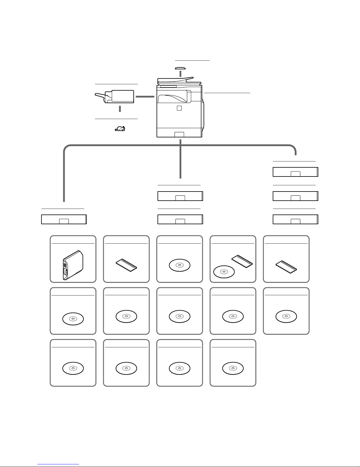
1. System configuration
MX-B381/B401
Digital multifunctional system
MX-CSX1
500-sheet paper feed unit
MX-CSX1
500-sheet paper feed unit
MX-CSX1
500-sheet paper feed unit
MX-BTX1
Business card feeder
MX-CSX2
500-sheet paper feed unit
MX-CSX2
500-sheet paper feed unit
MX-FN12
Finisher
MX-CSX2
500-sheet paper feed unit
AR-PF1
Bar code font kit
MX-FWX1
Internet fax expansion kit
MX-PUX1
XPS expansion kit
MX-USX1
Sharpdesk 1 license kit
MX-AMX1
Application integration
module
MX-AMX2
Application communication
module
MX-AMX3
External account module
MX-FXX3
Facsimile expansion kit
MX-SMX3
Expansion memory board
MX-USX5
Sharpdesk 5 license kit
MX-US10
Sharpdesk 10 license kit
MX-US50
Sharpdesk 50 license kit
MX-USA0
Sharpdesk 100 license kit
MX-FR16U
Data security kit
(Commercial version)
MX-SCX1
Staple cartridge
Page 4
MX-B381/B401 CONFIGURATION - ii
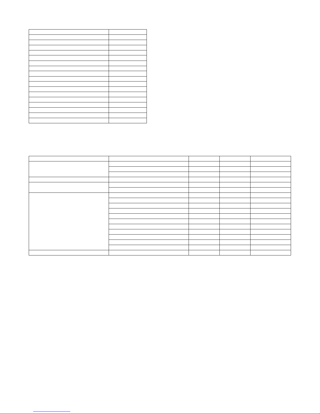
2. Machine configuration
STD: Standard provision, OPT: Option, –: No setting
*1: Product key target
3. Option list
STD: Standard provision, OPT: Option, –: No setting
*1: To install the MX-PUX1, the MX-SMX3 is required.
MX-B381/B401
Main body LCD CL 8.5
RSPF STD
Automatic duplex STD
HDD STD
System memory (For Program, Printer) 512MB
Local memory (Copier) 512MB
Copier STD
GDI printer –
SPDL/PCL printer STD
PS printer STD
EFI printer –
FAX OPT
Internet Fax OPT *1
Network scanner STD
Filing STD
Security OPT *1
OSA Expansion enable
Model Name Model name MX-B381/B401 Product key target
Paper feed system 500-sheet paper feed unit MX-CSX1 OPT –
500-sheet paper feed unit MX-CSX2 OPT –
Business card feeder MX-BTX1 OPT –
Paper exit system Finisher MX-FN12 OPT –
Electrical system (ROM) Bar code font kit AR-PF1 OPT –
Data security kit MX-FR16U OPT Yes
Electrical system (Software) Internet fax expansion kit MX-FWX1 OPT Yes
XPS expansion kit MX-PUX1 OPT *1 Yes
Sharpdesk 1 license kit MX-USX1 OPT –
Sharpdesk 5 license kit MX-USX5 OPT –
Sharpdesk 10 license kit MX-US10 OPT –
Sharpdesk 50 license kit MX-US50 OPT –
Sharpdesk 100 license kit MX-USA0 OPT –
Application integration module MX-AMX1 OPT Yes
Application communication module MX-AMX2 OPT Yes
External account module MX-AMX3 OPT Yes
Facsimile expansion kit MX-FXX3 OPT –
Memory Expansion memory board MX-SMX3 OPT –
Page 5
MX-B381/B401 MX-B381/B401 (MAIN UNIT) 1 – 1
MX-B401
Service Manual
[1] MX-B381/B401 (MAIN UNIT)
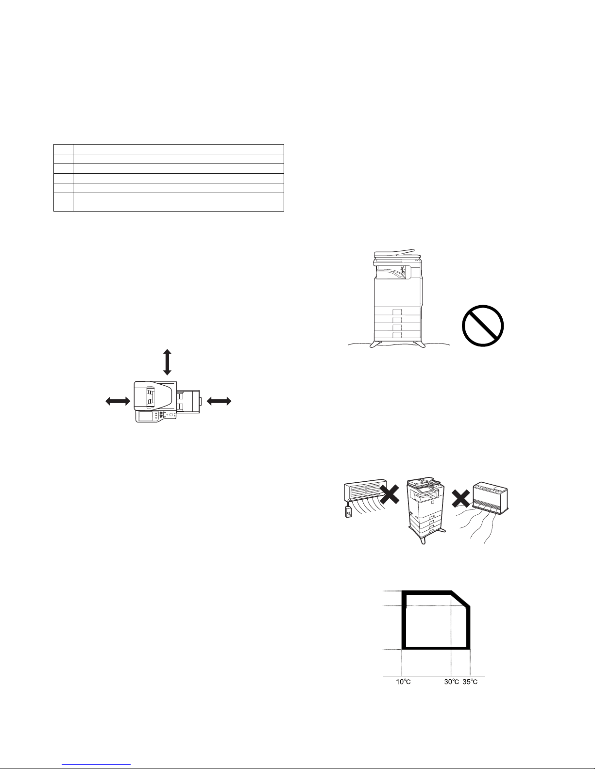
1. Installing (use) conditions
Before installing the machine, check that the following installing
(use) conditions are satisfied.
If the installing (use) conditions are not satisfied, the machine may
not display full performances, resulting in troubles. It may also
cause safety problems. Therefore, be sure to arrange the installing
(use) conditions before setting up the machine.
A. Bringing space
For installation of a large size machine, be sure to check that the
door size is wide enough before bringing in.
B. Installing space
The following space must be provided around the machine in order
to assure machine performances and proper operations.
If any option is installed, provide the additional space for installing
it.
Especially the space at the rear of the machine must be provided
sufficiently. If not, the machine cannot exhibit functions against heat
and dust, causing some troubles.
C. Power source (Capacity, voltage, frequency,
safety, plug)
If the power specifications are not satisfied, the machine cannot
exhibit full performances and may cause safety trouble.
Strictly observe the following specifications.
(1) Power capacity
Check that the following power capacity is satisfied. If not, additionally provide a power source.
Current capacity
Japan: 20A or more
100V: 15A or more
200V: 10A or more
(2) Power voltage
Measure the voltage during copying to check that the voltage is in
the range of the specified voltage 10%.
If the voltage is outside the specified range, use thicker lead wires
to reduce impedance.
(An electrical work is required.)
Use of a step-up transformer is also available. In this case, the
capacity must be great enough for the max. power consumption of
the machine.
(3) Power frequency, waveform
The frequency must be within the range of the specified frequency
2%. If power waveform is deformed, a trouble may occur.
(4) Safety
Be sure to properly ground the machine.
Grounding (earth connection) must be performed before inserting
the power plug into the power outlet.
When disconnecting the earth connection, be sure to disconnect
the power plug from the power outlet in advance.
(5) Power plug
Check the form of the power plug. If the shape does not match, do
not use it.
D. Floor strength and level
This machine is considerably heavy and becomes heavier with an
option installed.
The floor must be strong enough for assuring safety.
If the unit is not horizontally installed, the toner density control is not
performed normally, degrading the copy quality.
If not, color shift or image distortion may occur.
E. Direct rays of the sun, dust, temperature,
humidity, gasses, chemicals, vibration
(1) Temperature and humidity
This machine is designed to perform properly under the specified
temperature and humidity. If the temperature and humidity exceeds
the specified range, the machine may not operate properly and or
cause equipment failure.
Especially when the humidity is too high, paper absorbs humidity to
cause a paper jam or dirty copy.
Do not install the machine near a heater, a cooler, or a humidifier.
Dew may be formed inside the machine to cause a trouble. Use
enough care for ventilation.
• Working environment
Temperature: 10 to 35C
Humidity: 20 to 85% RH
Atmospheric pressure: 590 to 1013hPa (altitude: 0 to 2000 m)
No. Content
1 Bringing space
2 Installing space
3 Power source (Capacity, fluctuation, safety)
4 Floor strength
5 Direct rays of the sun, dust, temperature, humidity, gases,
chemicals
11-13/16”
(30cm)
11-13/16”
(30cm)
17-23/23”
(45cm)
85%
Humidity㧔RH㧕
60%
20%
Page 6

MX-B381/B401 MX-B381/B401 (MAIN UNIT) 1 – 2
(2) Dust
If dust enters the machine, it may cause dirty copy and a paper
jam, resulting in a shortened lifetime.
(3) Direct rays of the sun
If the machine is installed under the rays of the sun, the exterior of
the machine may be discolored and abnormal copies may be produced.
(4) Gases and chemicals
Do not install the machine at a place where there are gases and
chemicals. Especially be careful to avoid installation near a diazotype copier, which produces ammonium gas.
Copy quality may be adversely affected and a trouble may be
caused.
(5) Vibration
Avoid installation near a machine which produces vibrations.
If vibrations are applied to the copier machine, copy images may be
deflected and a trouble may be caused.
2. Transit and delivery
A. Implements, facility, and manpower
It is recommendable to use a forklift for bringing in the machine for
safety.
If no forklift is available, man-power of two persons is required. The
machine is considerably heavy, and requires safety precautions for
delivery and installation.
Transit of the machine must be made in packed condition to the
installing place.
Since the hard disk drive is built in the machine, use care not to
exert vibrations or shocks to the machine when in transit.
B. Delivery
Remove the packing materials prior to installation in the office environment.
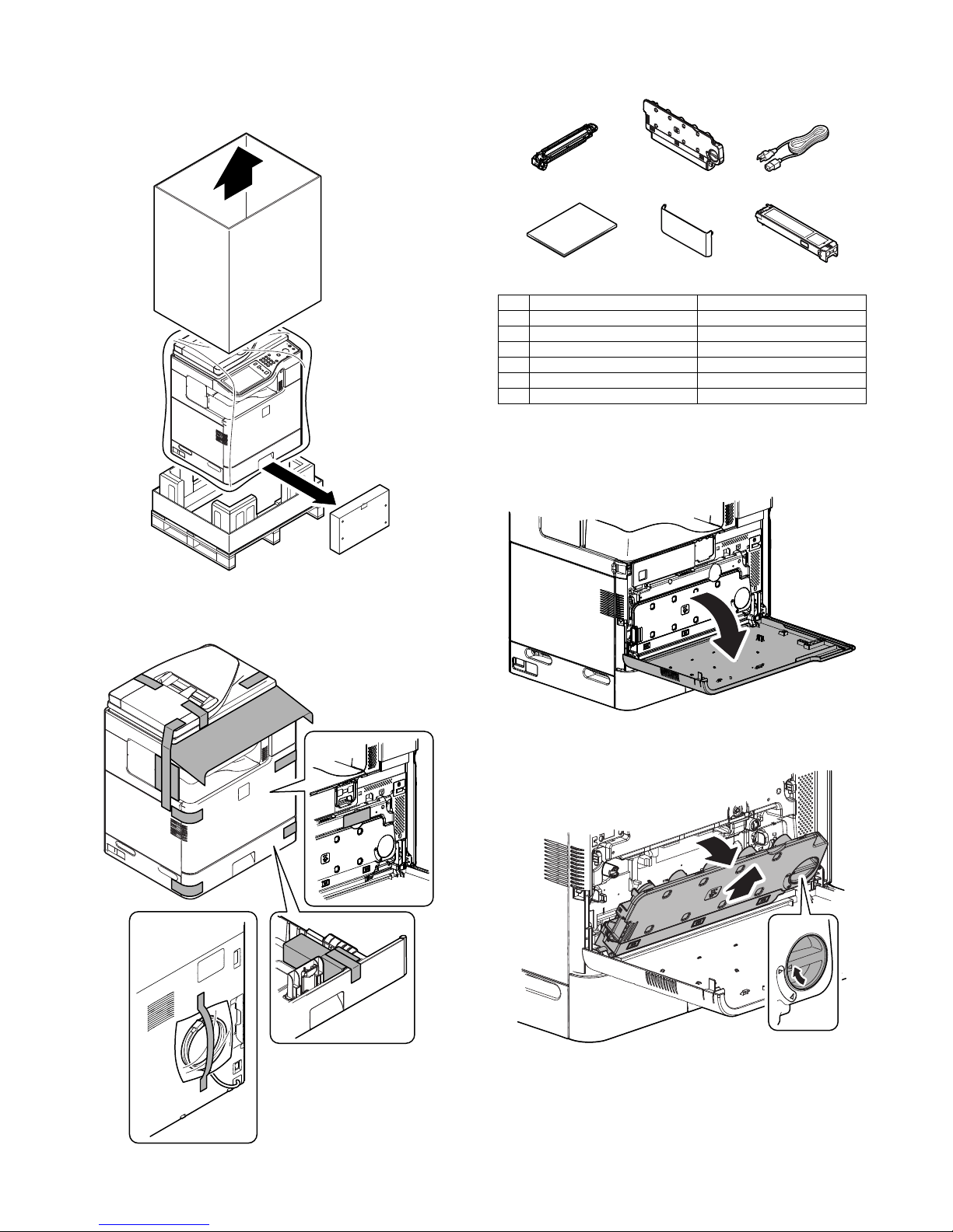
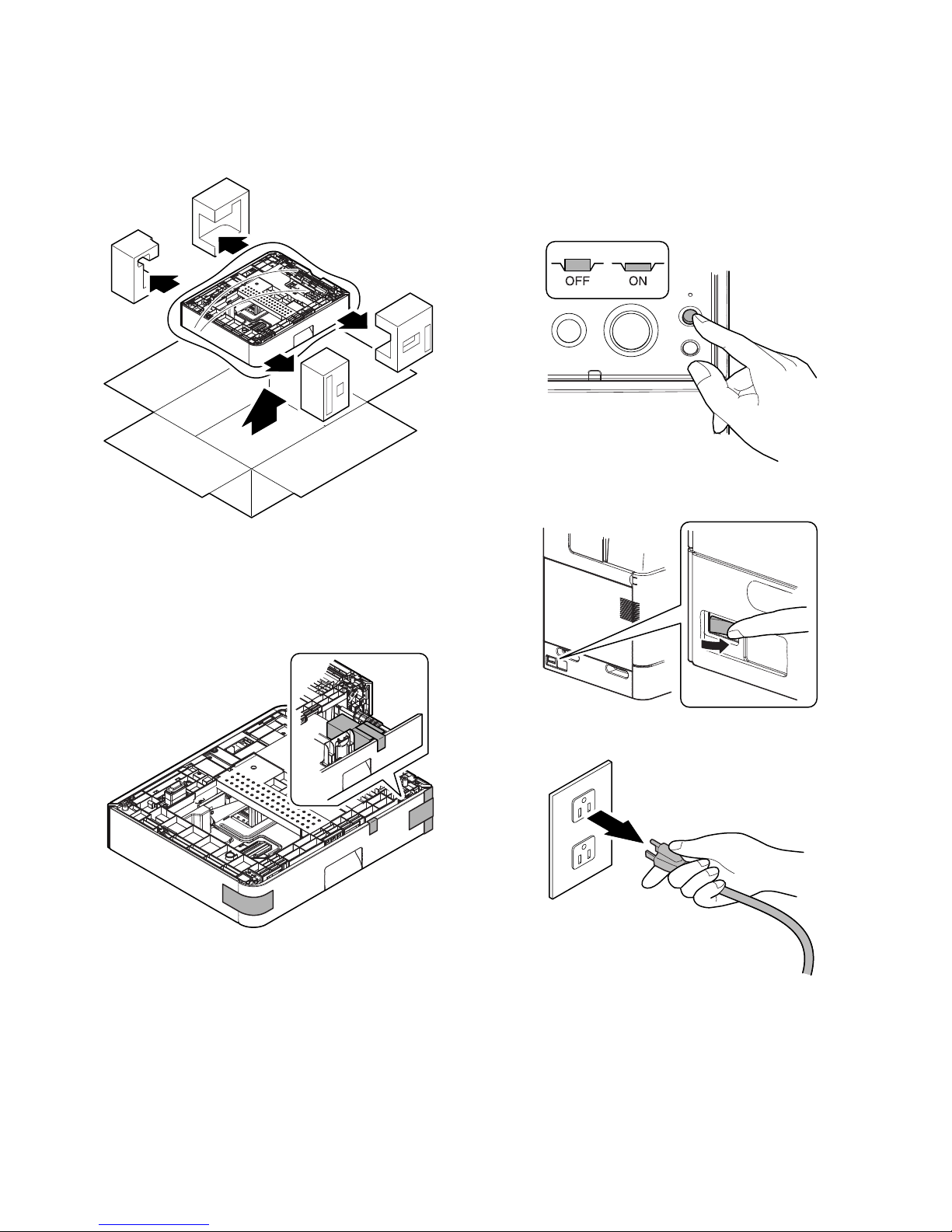
3. Unpacking
A. Unpacking procedure
1) Remove the PP band.
2) Remove the top case.
3) Remove the parts included in the package.
No. Content Method
1 Implements, facility,
and man power
Use a forklift. (If no forklift is available,
manpower of two persons is required.)
2 Delivery Transit must be made in packed condition.
Page 7
MX-B381/B401 MX-B381/B401 (MAIN UNIT) 1 – 3
4) Remove the carton.
5) Remove the parts included in the package.
6) Remove the main unit from the bottom padding, and remove
the polyethylene bag.
B. Removal of the fixing tape and protection
material
C. Check the packed items
1) Check that all the parts are in the package.
4. Installation
A. Installation of the developer cartridges
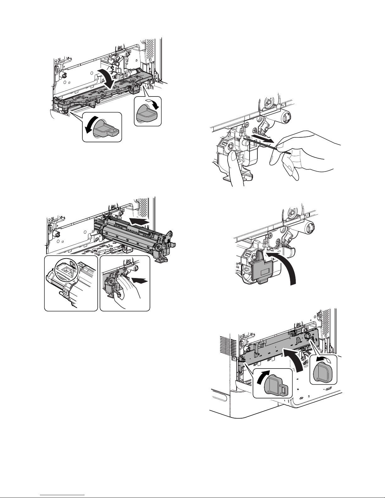
1) Open the front cover.
2) Turn the lock lever until it stops to release the lock, and
remove the waste toner box.
NOTE:
For North America, the power
cable is attached vertically to
the machine.
No. Packed part names Quantity
1 Developer cartridge 1
2 Waste toner box 1
3 AC cord 200V series only: 1 piece
4 Operation Manual 1 set
5 Operation Manual pocket Yes
6 Toner cartridge Europe only: 1 piece
12
456
3
Page 8
MX-B381/B401 MX-B381/B401 (MAIN UNIT) 1 – 4
3) Turn the lock lever to the horizontal position to release the
lock, and open the drum positioning plate unit.
4) Shake the developer cartridge 5 - 6 times horizontally, and
remove the protection material from the developer cartridge.
Insert the developer cartridge straight and horizontally until it
locks.
NOTE: When handling the developer cartridge, do not touch the
magnet roller section and the shutter section.
5) While pressing the developer cartridge, pull out the heat seal
straight.
NOTE: If the heat seal is pulled out with a strong force or diago-
nally, it may be broken off. Be sure to pull it slowly and
straight.
After puling out the heat seal completely, check to confirm
that there is a red mark at the edge of the heat seal.
If there is no red mark, it means that the heat seal has been
broken. In such a case, the developer cartridge must be
replaced with a new one.
6) Close the lock cover of the developer cartridge.
7) Close the drum positioning plate unit, and put the lock lever
upright to lock.
Page 9
MX-B381/B401 MX-B381/B401 (MAIN UNIT) 1 – 5
B. Cleaning of LSU's dust-proof glass
* Dust from the transfer belt or shutter or some other adjacent part
may fall onto the LSU during transport or installation. Be sure to
clean the dust-proof glass before checking the image quality.
1) Remove the LSU cleaning rod from the front cover.
2) Face the cleaner downward, and slowly insert the LSU cleaning rod into the LSU cleaning hole.
* The LSU cleaning hole is indicated with a label.
3) After inserting the LSU cleaning rod to the bottom, pull it out
until the lead edge of the cleaning unit is separated from the
LSU clearing surface. Repeat 2 - 3 times for cleaning.
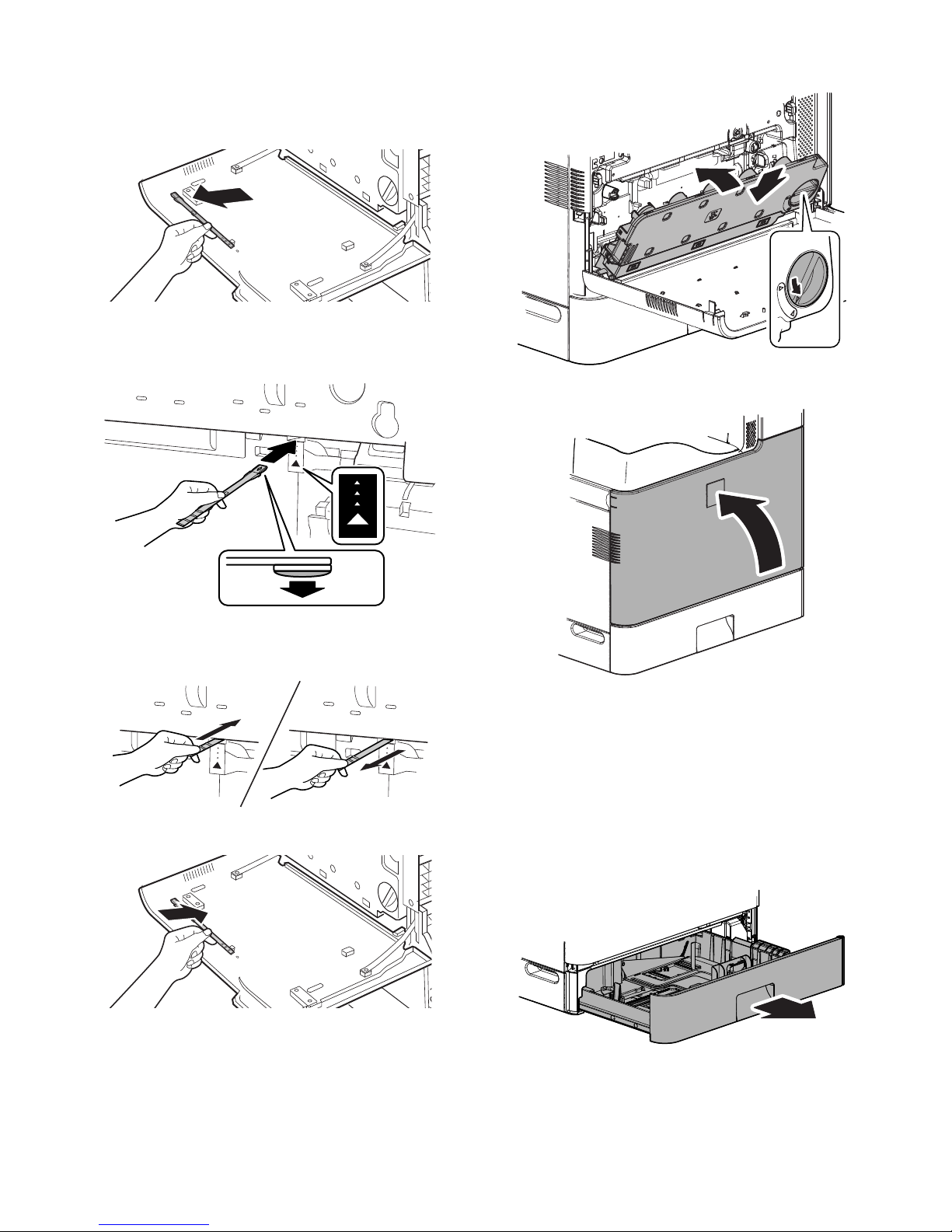
4) Return the LSU cleaning rod to the front cover.
5) Install the waste toner box, and turn the lock lever to the left
until it stops to lock the waste toner box.
6) Close the front cover.
C. Installation of the operation manual pocket
1) Install the Operation Manual pocket (included in package)
cover to the left side of the machine.
a) First, insert the pawl on the lower side of the Operation
Manual pocket.
b) Then, lift the pawl on the upper side and insert it, and slide
down to install.
D. Tray size setup
1) Gently pull out the tray until it stops. If paper remains in the
tray, remove it.
Cleaning
side
Page 10

MX-B381/B401 MX-B381/B401 (MAIN UNIT) 1 – 6
2) Adjust the guide plates A and B to the vertical size and the horizontal size of paper.
The guide plates A and B are movable. Hold the fixing knob to
slide the guide plates A and B to match the paper size.
3) Insert the tray slowly.
The machine automatically detects the set paper size.
4) Close the cabinet and turn on the power.
The toner concentration adjustment operation is automatically
started, and "Please wait. Do not turn the power off." is displayed.
When the toner concentration adjustment operation is completed, the message of "Install the toner cartridge." is displayed. Do not make any operations until the message is
displayed.
E. Installation of toner cartridges
* The life of each toner cartridge is as follows:
Equivalent to approximately 2.5K (A4/LT 5%)
1) Shake the toner cartridge (included in package) horizontally
several times.
2) Remove the heat seal.
3) Insert the toner cartridge horizontally and straight until it locks.
NOTE: Do not forcibly insert the toner cartridge. Keep holding the
cartridge and completely insert it.
NOTE: When the machine is transported with the developing unit
removed, be sure to remove the toner cartridge. (if not
toner may become clogged.)
NOTE: Do not remove or insert the toner cartridge with the devel-
oper cartridge removed.
F. Specifications setting
Use SIM26 to set to the specifications according to the customer's
request.
To customize one of the following items after destination setting,
change the set value of the item.
SIM No Content
26 6 Destination setting
SIM No Content
26 3 Auditor specifications, mode setting
18 Toner save mode enable/disable setting (Japan and UK
versions only)
* For the other destinations, this setting is made by the user
program.
52 Count-up enable/disable setting of non-print paper passing for
each counter
53 User auto calibration enable/disable setting
65 Staple limit quantity setting
Page 11
MX-B381/B401 MX-B381/B401 (MAIN UNIT) 1 – 7
G. Image off-center adjustment
Make a copy in the document table mode and in the RSPF mode,
and check to confirm that the void area is within the specified range
shown below.
NOTE: When an option cassette is installed, execute this adjust-
ment.
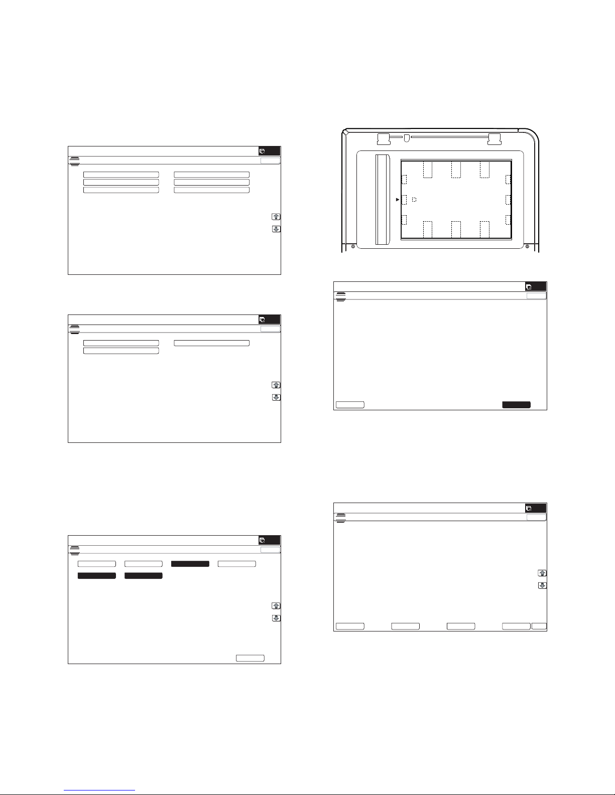
(1) Image off-center automatic adjustment
(Document table mode)
1) Enter the SIM50-28 mode.
2) Select [SETUP/PRINT ADJ].
3) Select [OFFSET].
(Note)
When [ALL] is selected, the adjustments of the following two
items are performed at a same time.
* [LEAD]: Print image lead edge image position adjustment
* [OFFSET]: Print image off-center adjustment
4) Select a paper feed tray to be adjusted.
Set A4 (11" x 8.5") paper in each paper feed tray in advance.
5) Press [EXECUTE] key.
The adjustment pattern is printed out. (Paper is fed from the
selected paper feed tray, and the adjustment pattern of each
paper feed tray is printed out.)
6) Set the adjustment pattern to the center reference position on
the document table.
NOTE: Fit the adjustment pattern correctly with the document
guide.
7) Press [EXECUTE] key.
The following item is automatically adjustment.
* Print image lead edge image position adjustment
* Print image off-center adjustment
Perform the procedures of 6) - 7) for the printed adjustment
pattern of each paper feed tray.
8) Press [OK] key.
The adjustment result becomes valid.
NOTE: When an error occurs in the automatic adjustment of
SIM50-28, place white paper on the adjustment pattern and
perform the adjustment.
ǂǂǂ6,08/$7,21ǂǂ12
&/26(
7(67
$872,0$*(326,7,21$'-8670(176(59,&(
2&$'-
%.0$*$'-
63)$'-
66(78335,17$'-
5(68/7
'$7$
ǂǂǂ6,08/$7,21ǂǂ12
&/26(
7(67
$872,0$*(326,7,21$'-8670(176(59,&(
/($'
2))6(7
$//
ǂǂǂ6,08/$7,21ǂǂ12
&/26(
7(67
$872,0$*(326,7,21$'-8670(176(59,&(
(;(&87(
0)7
&6
$'8
&6
&6
&6
ǂǂǂ6,08/$7,21ǂǂ12
&/26(
7(67
$872,0$*(326,7,21$'-8670(176(59,&(
3/($6(:$,7
12:(;8&87,1*
(;(&87(
5(35,17
ǂǂǂ6,08/$7,21ǂǂ12
&/26(
7(67
$872,0$*(326,7,21$'-8670(176(59,&(
35,17/($'0)7&$6$'8
&$6'6.
35,172))6(70)7&$6&$6$'8
&$6&$6
'$7$
5(6&$1
5(35,17
5(75<
2.
Page 12
MX-B381/B401 MX-B381/B401 (MAIN UNIT) 1 – 8
H. Remote operation panel function Enable
setting
(1) General
To use the remote operation panel function, the password for the
remote operation panel function must be entered on the password
input menu displayed on the VNC boot screen. Note that, therefore,
the password must be set in advance to use the remote operation
panel function.
Let the user make the password, and use SIM26-78 to set it.
(2) Remote operation panel function password setting
procedures
1) Enter the SIM26-78 mode.
2) Enter the password with 10 key. (Within 5 - 8 digits)
The entered password is displayed on the column of "NEW."
To modify the entered password, use clear key to delete the
password digit by digit.
3) Press [SET] key, and the password is set.
I. Functional operation check
Check to confirm that the following operations are normal.
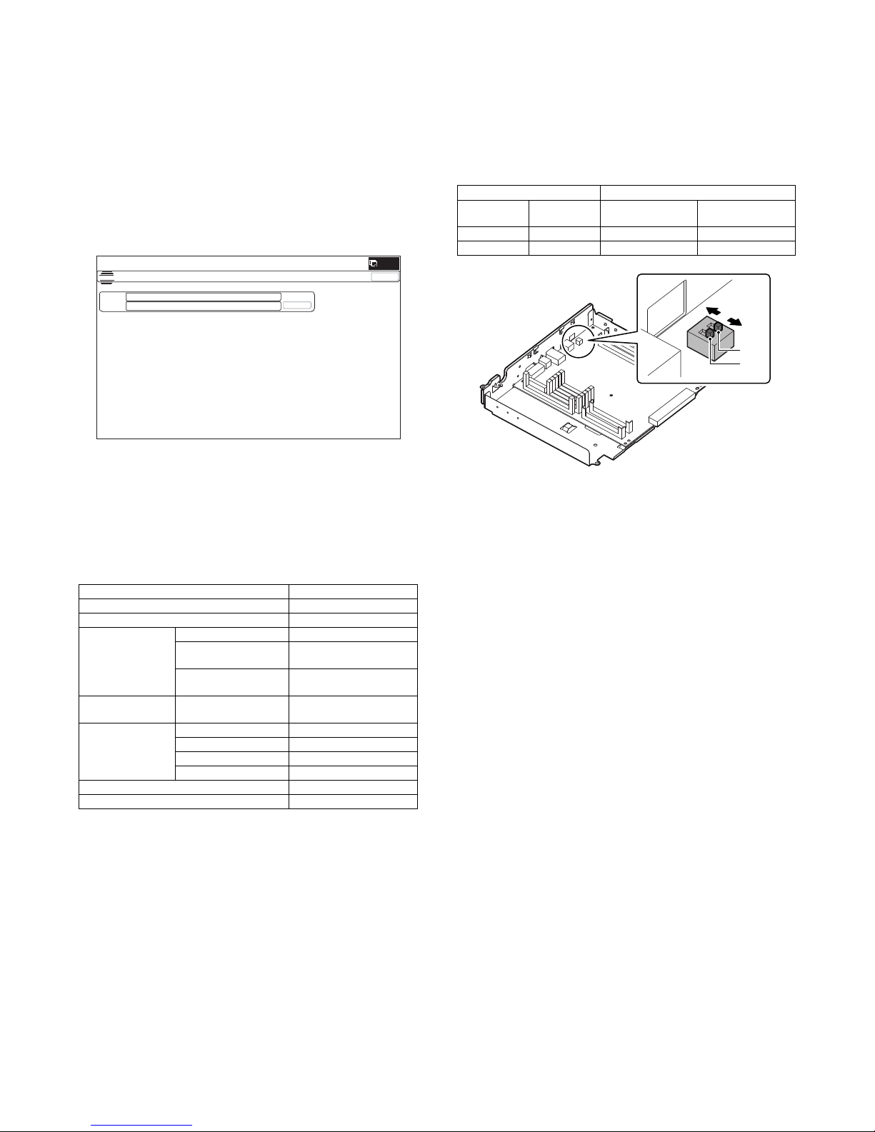
J. USB PORT selection
There are two USB ports, one on the rear frame side and the other
on the front frame side. Only either of them can be used.
When shipping, the port on the front frame side is valid and the port
on the rear frame side is invalid.
The valid port can be switched by changing the setting of the MFP
PWB DIP SW.
Select the valid USB port according to the user's request.
K. Storing setting and adjustment data
Use SIM22-6 to print and store the settings and adjustments data
(list).
• When a memory trouble occurs, if the above information is not
available, all the adjustments must be performed from the beginning.
• If the above information is available, the setting and adjustment
values can be directly entered, shortening the servicing time.
L. Procedures required for transit of the machine
1) If the following option is installed, remove it from the machine.
• Finisher
2) Remove the following consumable parts from the machine.
• Paper
• Toner cartridge
• Developer cartridge
NOTE: When moving take extreme care to prevent shock or vibra-
tion to the machine as there is a hard drive built into this
product.
Check item Equipment
Key input operation (Operation panel)
Display (Operation panel)
Paper feed
operation
Manual paper feed
Main unit paper feed
tray
Option paper feed unit With the option paper feed
unit installed
Paper size
detection operation
Manual paper feed tray
RSPF operation /
Duplex copy
operation
S-S mode
D-S mode
S-D mode
D-D mode
Stapling operation With the finisher installed
Offset operation With the finisher installed
ǂǂǂ6,08/$7,21ǂǂ12
&/26(
7(67
523(3$66:25'6(77,1*
35(6(17˖
ǂǂ1(:˖
MFP PWB DIP SW USB I/F
SW 1 SW 2
Port on the front
frame side
Port on the rear
frame side
OFF OFF Valid Invalid
OFF ON Invalid Valid
SW1
ON
OFF
SW2
Page 13
MX-B381/B401 MX-CSX1/CSX2 (500-SHEET PAPER FEED UNIT) 2 – 1
MX-B401
Service Manual
[2] MX-CSX1/CSX2 (500-SHEET PAPER FEED UNIT)
1. Unpacking
A. Removal of the 500 sheet paper feed unit
(1) MX-CSX1/CSX2
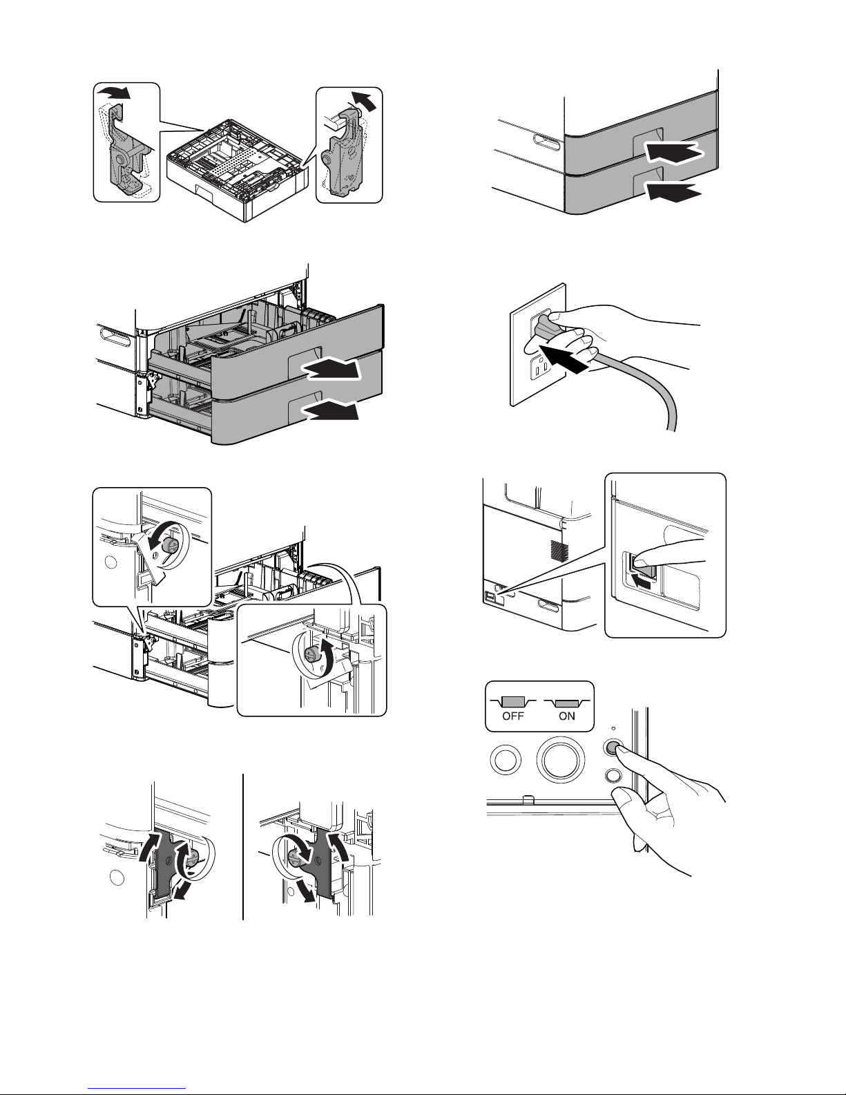
B. Removal of the fixing tape and protection
material
(1) MX-CSX1/CSX2
1) Remove the 500 sheet paper feed unit from the polyethylene
bag, and remove the fixing tape and the protection material.
2. Installation
<Precautions for installation>
Before execution of installation, check to confirm that the communication lamp on the operation panel and the data lamp under it are
not lighted or blinking.
A. Turn off the power of the main unit
1) Turn OFF the power switch on the operation panel.
2) Check to confirm that the operation panel is turned OFF, and
then turn OFF the power switch.
3) Disconnect the power plug from the power outlet.
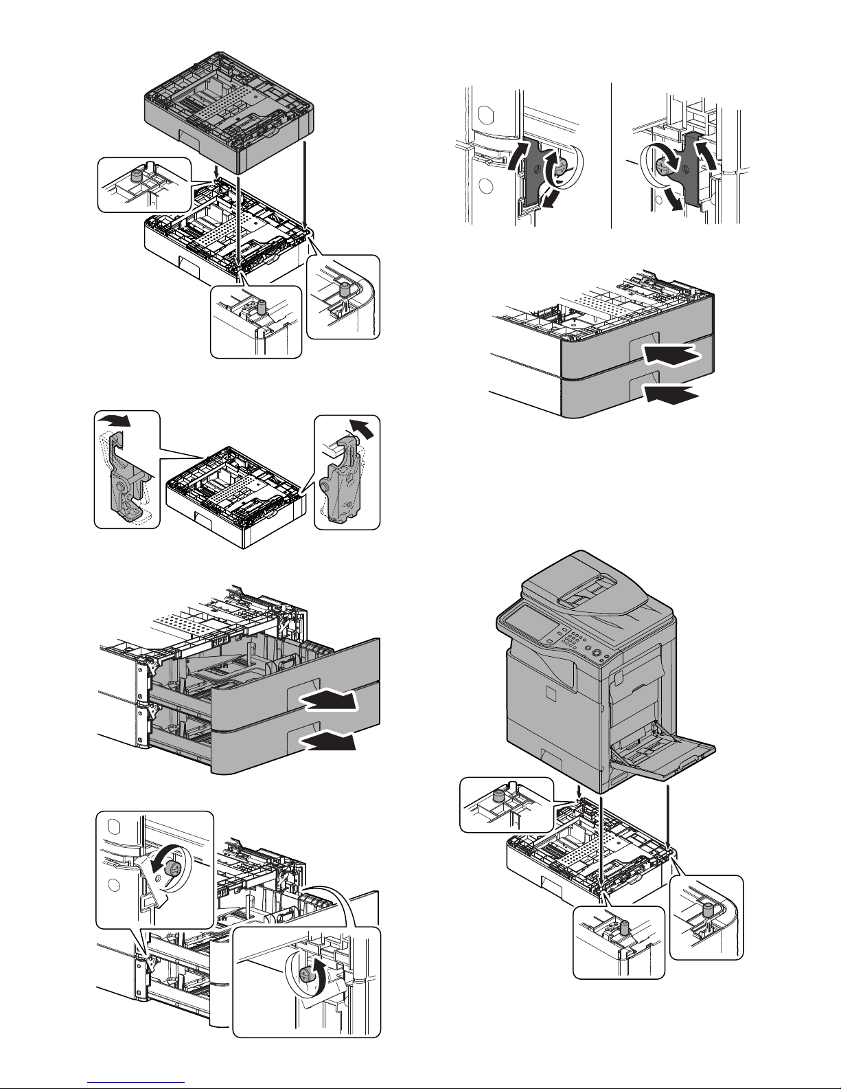
B. Install the MX-CSX1 or the MX-CSX2 to the MX-
CSX2.
* In the example below, installation of the MX-CSX1 to the MX-
CSX2 is described. Installation of the MX-CSX2 to another MXCSX2 is performed similarly.
1) Put the MC-CSX1 on the MX-CSX2 so that they fit together.
NOTE: When holding the main unit with the MX-CSX2 and the
MX-CSX1 installed, use two persons.
Page 14
MX-B381/B401 MX-CSX1/CSX2 (500-SHEET PAPER FEED UNIT) 2 – 2
* When the MX-CSX1 is put on the MX-CSX2, it is automati-
cally locked at the left and the right of the rear side.
2) Pull out the trays of the MX-CSX1 and the MX-CSX2.
3) Loosen the hand screws on the left and the right sides.
4) Hang the fixing clasp on the main unit, and tighten the hand
screws.
5) Push in and close the trays.
C. Install the main unit to the MX-CSX1.
NOTE: If the main unit is combined with the MX-CSX1 only, it must
be used as a desktop machine and must not be used on
the floor in order to prevent against falling.
1) Put the main unit on the MX-CSX1 so that they fit together.
NOTE: When holding the main unit, use two persons.
Page 15
MX-B381/B401 MX-CSX1/CSX2 (500-SHEET PAPER FEED UNIT) 2 – 3
* When the main unit is put on the MX-CSX1, it is automati-
cally locked at the left and the right of the rear side.
2) Pull out the tray of the main unit and that of the MX-CSX1.
3) Loosen the hand screws on the left and the right sides.
4) Hang the fixing clasp on the main unit, and tighten the hand
screws.
5) Push in and close the trays.
D. Turn on the power of the main unit
1) Power to the main unit.
2) Turn ON the power switch.
3) Turn ON the power switch on the operation panel.
Page 16
MX-B381/B401 MX-CSX1/CSX2 (500-SHEET PAPER FEED UNIT) 2 – 4
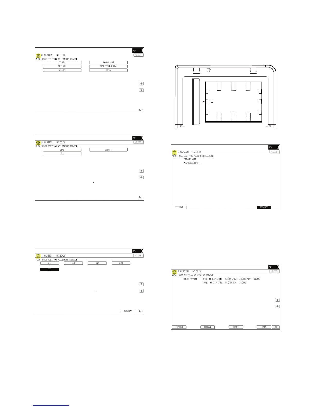
3. Adjustments
A. Image off-center automatic adjustment
(Document table mode)
1) Enter the SIM50-28 mode.
2) Select [SETUP/PRINT ADJ].
3) Select [ALL].
NOTE: When [ALL] is selected, the adjustments of the follow-
ing two items are performed at a same time.
* [LEAD]: Print image lead edge image position adjustment
* [OFFSET]: Print image off-center adjustment
4) Select the paper feed trays to be adjusted. (Select all the
trays.)
Set A4 (11" x 8.5") paper in each paper feed tray in advance.
5) Press [EXECUTE] key.
The adjustment pattern is printed out. (Paper is fed from the
selected paper feed tray, and the adjustment pattern of each
paper feed tray is printed out.)
6) Set the adjustment pattern in the center reference on the document table.
NOTE: Fit the adjustment pattern correctly with the document
guide.
7) Press [EXECUTE] key.
The following item is automatically adjustment.
* Print image lead edge image position adjustment
* Print image off-center adjustment
Perform the procedures of 6) - 7) for the printed adjustment
pattern of each paper feed tray.
8) Press [OK] key. (For the 4.3 Inch LCD model, press the OSA
shortcut key.)
The adjustment result becomes valid.
NOTE: When an error occurs in the automatic adjustment of
SIM50-28, place white paper on the adjustment pattern and
perform the adjustment.
Page 17

MX-B381/B401 MX-FN12 (FINISHER) 3 – 1
MX-B401
Service Manual
[3] MX-FN12 (FINISHER)
1. Unpacking
A. Removal of the finisher
B. Removal of the fixing tape and protection
material
1) Remove the finisher from the polyethylene bag, and remove
the fixing tape and the protection materials.
C. Check the packed items
2. Installation
<Precautions for installation>
Before execution of installation, check to confirm that the communication lamp on the operation panel and the data lamp under it are
not lighted or blinking.
A. Turn off the power of the main unit
1) Turn OFF the power switch on the operation panel.
2) Check to confirm that the operation panel is turned OFF, and
then turn OFF the power switch.
3) Disconnect the power plug from the power outlet.
No. Packed part names Quantity
1 Machine connection unit 1
2 Paper exit tray 1
3 Staple position label (For RSPF) 1
4 Staple position label (For OC) 1
21
43
Page 18

MX-B381/B401 MX-FN12 (FINISHER) 3 – 2
B. Installation of the machine connection unit
1) Remove the full detection actuator and the paper exit auxiliary
plate at the paper exit port of the main unit.
2) Disengage the pawls, and remove the paper exit cover.
3) Open the front cover.
4) Remove the coin screw, and remove the paper exit tray.
5) Install the machine connection unit (included in the package)
to the machine.
6) Slide the lock lever to " (Lock)" position and fix it.
C. Installation of the finisher
1) Install the finisher to the machine connection unit.
NOTE: When holding the finisher, hold the front frame side and
the rear frame side together.
2) Close the front cover of the finisher.
Page 19

MX-B381/B401 MX-FN12 (FINISHER) 3 – 3
3) Close the front cover of the main unit.
D. Installation of the paper exit tray
1) Install the paper exit tray (included in the package) to the finisher.
E. Staple position label attachment
1) Attach the staple position label (included in the package) for
the RSPF to the RSPF unit.
2) Attach the staple position label (include in the package) for the
OC to the scanner unit.
F. I/F cable connection
1) Remove the cap of the connector for connecting the finisher to
the rear side of the machine.
Connect the I/F cable of the finisher, and loosen the manual
screw of the connector and fix it.
Non LPS
Do not connect to devices other than specified peripheral
devices of our company.
G. Turn on the power of the main unit
1) Insert the power plug into the power outlet.
Page 20

MX-B381/B401 MX-FN12 (FINISHER) 3 – 4
2) Turn ON the power switch.
3) Turn ON the power switch on the operation panel.
3. Adjustments
The adjustments of this machine are executed only when a
trouble occurs.
If the adjustment value is changed when there is no trouble in the
machine, a trouble may be generated such as improper alignment
of paper, paper exit jam, attachment of roller marks on paper, etc.
A. Paper alignment width adjustment
This adjustment is executed when a trouble occurs in paper alignment.
1) Execute Sim3-10.
2) Select "A: FPAM ADJUST".
3) Enter the set value with 10-key. (Press [C] key to clear the
entered values.)
Initial value: 50
When the adjustment value is increased by 1, the alignment
plate F/R width is narrowed by 0.419mm in alignment operation.
When the adjustment value is decreased by 1, the alignment
plate F/R width is widened by 0.419mm in alignment operation.
The alignment plate F and the alignment plate R cannot be
adjusted separately. The shift amount on the F side and that
on the R side are alternatively corrected every-time the adjustment value is increased by 1. (Correction with 51 for the F
side, and 52 for the R side. ... 59 for the F aide, and 60 for the
R side. Similar when the set value is decreased.)
4) Press [OK] key to save the set value. (For the 4.3 Inch LCD
model, press the OSA shortcut key.)
5) After completion of the adjustment, make staple copies.
Alignment specification: Within 2.5mm
B. Paper delivery roller descending position
adjustment
This adjustment is executed when a paper exit jam occurs or when
roller marks of the paper delivery roller are attached to paper.
1) Execute Sim3-10.
2) Select "B: FDRLM ADJUST".
3) Enter the set value with 10 key. (Press [C] key to clear the
entered values.)
Initial value: 50
When the adjustment value is increased by 1, the shift amount
of the paper delivery roller is changed by 0.11mm toward the
pressure increasing side (*1).
When the adjustment value is decreased by 1, the shift
amount of the paper delivery roller is changed by 0.11mm
toward the pressure decreasing side (*1).
*1: The pressure increasing side means the direction to
increase the paper delivery roller pressure onto paper, and
the pressure decrease side means the direction to
decrease the paper delivery roller pressure onto paper.
4) Press [OK] key to save the set value.
B
Page 21

MX-B381/B401 MX-FXX3 (FACSIMILE EXPANSION KIT) 4 – 1
MX-B401
Service Manual
[4] MX-FXX3 (FACSIMILE EXPANSION KIT)
1. Unpacking
A. Check the packed items
2. Installation
<Precautions for installation>
Before execution of installation, check to confirm that the communication lamp on the operation panel and the data lamp under it are
not lighted or blinking.
A. Turn off the power of the main unit
1) Turn OFF the power switch on the operation panel.
2) Check to confirm that the operation panel is turned OFF, and
then turn OFF the power switch.
3) Disconnect the power plug from the power outlet.
B. FAX unit installation
1) Remove the two screws on the rear cabinet of the main unit.
Attach the step screw (included in the package) to one of the
removed screw positions.
No. Packed part names Quantity
1 FAX memory 1
2 Ferrite core 1
3 Line cable 1
4 Screw (M3) 1
5 Step screw 1
6 Clamp 1
7 Instructions for installation 1
2
45 76
1
3
Australia
Page 22

MX-B381/B401 MX-FXX3 (FACSIMILE EXPANSION KIT) 4 – 2
2) Hang the FAX unit on the step screw. Fix the FAX unit with the
screws which were removed in the step 1).
C. FAX memory installation
1) Open the front cover and the tray 1.
2) Remove the stopper, and slide the left cabinet to the front side
to remove.
3) Remove the screw, and remove the controller cover.
4) Install the FAX memory (included in the package) to the slot E
for an option of the MFPC PWB.
D. I/F cable connection
1) Connect the I/F cable to the FAX unit of the MFPC PWB.
Attach the clamp (included in the package) and pass the I/F
cable through the clamp.
NOTE: Check to confirm that the connector is not inserted
obliquely.
Page 23

MX-B381/B401 MX-FXX3 (FACSIMILE EXPANSION KIT) 4 – 3
2) Cut off the notch section of the rear cabinet. Attach the I/F
cable to the rear cabinet and the frame, and fix the banding
band with the screw (M3) (included in the package).
3) Attach the controller cover, and fix it with the screw.
4) Attach the left cabinet by using care for the hook, and fix the
stopper.
5) Close the front cover and the tray 1.
E. Turn on the power of the main unit
1) Insert the power plug into the power outlet.
2) Turn ON the power switch.
3) Turn ON the power switch on the operation panel.
F. Set the destination and the logo type.
1) Switch the operation panel to the copy mode and use the key
operation [P], [], [C], and [] to enter the simulation mode.
2) Use the numeric keys to enter [26] in the main code entry
screen shown below and press the [START] key.
SIMULATION
INPUT A MAIN NUM BY 10-KEY, AND PRESS START
01: SCANNER CHECK
02: SPF CHECK
03: AFTER PROCESS CHECK
04: DESK/LCC CHECK
05: PANEL/LAMP CHECK
06: MFP CHECK
07: AGING
TEST
1/9
CLOSE
26
Page 24

MX-B381/B401 MX-FXX3 (FACSIMILE EXPANSION KIT) 4 – 4
3) Use the numeric keys to enter [06] in the sub-code entry
screen shown below and press the [START] key.
4) Press the desired destination on the touch panel and press
[EXECUTE] to highlight it.
5) Press the [CA] key or the [SYSTEM SETTINGS] key to exit
from the simulation mode. The message [PLEASE TURN
MAIN POWER OFF THEN ON] is displayed.
Restart the machine to change the destination.
• List of destinations
G. Clear the FAX related software switches.
1) Switch the operation panel to the copy mode and use the key
operation [P], [], [C], and [] to enter the simulation mode.
2) Use the numeric keys to enter [66] in the main code entry
screen shown below and press the [START] key.
3) Use the numeric keys to enter [02] in the sub-code entry
screen shown below and press the [START] key.
4) Use numeric keys [0] and [1] to enter the desired 8-digit country code.
After entry, press [SET], [EXECUTE], and [YES] in this order.
• Country code list screen
* Press the [DEST CODE] button on the initial screen to move to
the country code list screen.
To return to the input screen, press the [BACK] button.
Display Description
01: U.S.A U.S.A.
02: CANADA Canada
03: INCH Inch system, other destinations
04: JAPAN Japan
05: AB_B AB system (B5 size detectable), other destinations
06: EUROPE Europe
07: U.K. U.K.
08: AUS. Australia
09: AB_A AB system (A5 size detectable), other destinations
10: CHINA China
SIMULATION NO.26
INPUT A SUB NUM BY 10-KEY, AND PRESS START
01: RIGHT TRAY SETUP
02: SIZESETUP
03: AUDITOR SETUP
06: DESTINATION SETUP
10: NETWORK SCANNER TRIAL MODE SETUP
18: TONER SAVE MODE SETUP
30: CE MARK CONTROL SETTING
TEST
1/3
CLOSE
06
SIMULATION NO.26-06
DESTINATION SETUP
01:
TEST
05:
09:
03:
07:
02:
06:
10:
04:
08:
1/1
00
U.S.A.
AB_B
AB_A
CANADA
EUROPE
CHINA
INCH
U.K.
JAPAN
AUS.
CLOSE
EXECUTE
SIMULATION
INPUT A MAIN NUM BY 10-KEY, AND PRESS START
01: SCANNER CHECK
02: SPF CHECK
03: AFTER PROCESS CHECK
04: DESK/LCC CHECK
05: PANEL/LAMP CHECK
06: MFP CHECK
07: AGING
TEST
1/9
CLOSE
66
Country code list
JAPAN : 00000000 SWITZERLAND : 10100110
U.S.A. : 10110101 AUSTRIA : 00001010
AUSTRALIA : 00001001 INDONESIA : 01010100
U.K. : 10110100 THAILAND : 10101001
FR ANC E : 0 01111 01 MA LAYSI A : 011 011 00
GERMANY : 00000100 INDIA : 01010011
SWEDEN : 10100101 PHILIPPINES : 10001001
NE WZE AL AND : 0 1111110 HO NGKO NG : 01 010 00 0
CHINA : 00100110 RUSSIA : 10111000
SI N GA P ORE : 1 0 01110 0 SO UTH A FR I CA : 100 11111
TW : 11111110 SPAI N : 1 010 0 00 0
MIDDLEAND
NEAREAST
: 111111 0 1 PO RTU GUE S E : 1 0 00 1 011
SL OVAK I A : 111111 0 0 LU XEM B URG : 0 11 010 01
OT H ER 3 : 11111 0 11 BE LGI U M : 00 001111
FI NLA N D : 0 0 111100 C Z ECH : 0 010 1110
NORWAY : 10000010 HUNGARY : 01010001
DENMARK : 00110001 GREECE : 01000110
NE THE RL AND S : 0 1111011 PO LAN D : 1 000 10 10
ITALY : 01011001 BRAZIL : 00010110
SIMULATION NO.66
INPUT A SUB NUM BY 10-KEY, AND PRESS START
01: FAX SOFT SW. SETTING.
02: FAX SOFT SW. CLEAR.
03: FAX PWB MEMORY CHECK.
04: SIGNAL OUTPUT CHECK. (LEVEL MAX)
05: SIGNAL OUTPUT CHECK.(SOFT SW.)
06: PASS CODE PRINT OUT.
07: IMAGE MEMORY PRINT OUT.
TEST
1/5
CLOSE
02
SET
SIMULATION NO.66-02
CLOSE
FAX SOFT SW.CLEAR-U.S.A.
TEST
10110101PRESENT:
NEW:
SURE? YES
NO
EXECUTE
DEST CODE
SIMULATION NO.66-02
FAX SOFT SW.CLEAR
-
U.S.A.
JAPAN :00000000
AUSTRALIA :00001001
FRANCE :00111101
SWEDEN :10100101
U.S.A. :10110101
U.K. :10110100
GERMANY :00000100
NEWZEALAND :01111110
TEST
1/5
CLOSE
BACK
Page 25

MX-B381/B401 MX-FXX3 (FACSIMILE EXPANSION KIT) 4 – 5
H. Clear the image memory.
1) Switch the operation panel to the copy mode and use the key
operation [P], [], [C], and [] to enter the simulation mode.
2) Use the numeric keys to enter [66] in the main code entry
screen shown below and press the [START] key.
3) Use the numeric keys to enter [10] in the sub-code entry
screen shown below and press the [START] key.
4) In the sub menu screen shown below, press [EXECUTE] on
the touch panel.
After [YES] on the panel lights up, press it.
5) The screen shown below is displayed and memory clear operation is executed.
6) After several minutes, memory clear operation is completed
and the [YES] button goes out. Press the [CA] key to exit from
the simulation mode.
Then the main unit is automatically rebooted.
I. Line cable connection
1) Connect the line cable on the line to the modular jack indicated
as "LINE."
* When an external telephone is used, wind the line cable
around the ferrite core (included in the package) two turns,
and connect it to the modular jack indicated as "TEL."
* After connection, perform the setting of "External telephone
connection" of the system setting (administrator).
J. Installation completion check
1) Execute SIM 22-10 to check to confirm that the FAX box and
the FAX memory are properly installed.
When the FAX1 is properly connected, "MX-FXX3" is displayed.
When the FAX memory is properly connected, "AR-MM9" is
displayed.
SIMULATION
INPUT A MAIN NUM BY 10-KEY, AND PRESS START
01: SCANNER CHECK
02: SPF CHECK
03: AFTER PROCESS CHECK
04: DESK/LCC CHECK
05: PANEL/LAMP CHECK
06: MFP CHECK
07: AGING
TEST
1/9
CLOSE
66
SIMULATION NO.66
INPUT A SUB NUM BY 10-KEY, AND PRESS START
01: FAX SOFT SW. SETTING.
02: FAX SOFT SW. CLEAR.
03: FAX PWB MEMORY CHECK.
04: SIGNAL OUTPUT CHECK. (LEVEL MAX)
05: SIGNAL OUTPUT CHECK. (SOFT SW.)
06: PASS CODE PRINT OUT.
07: IMAGE MEMORY PRINT OUT.
TEST
1/5
CLOSE
10
SIMULATION NO.66-10
CLOSE
IMAGE MEMORY CLEAR.
TEST
SURE? YES NO
EXECUTE
SIMULATION NO.66-10
CLOSE
IMAGE MEMORY CLEAR.
TEST
SURE? YES NO
EXECUTE
App
r
oximately
1
0cm
SIMULATION NO.22-10
MACHINE SYSTEM
MACHINE : MX-B401
SPF : STANDARD
DESK : MX-CSX1
FINISHER : MX-FN12
FAX1:MX-FXX3
FAX MEMORY : AR-MM9
PS : MX-PKX5
XPS : MX-PUX1
SECURITY : MX-FR16U
AIMY : MX-AMX1
TEST
1/2
CLOSE
Page 26

MX-B381/B401 AR-PF1 (BARCODE FONT KIT) 5 – 1
MX-B401
Service Manual
[5] AR-PF1 (BARCODE FONT KIT)
1. Unpacking
A. Check the packed items
2. Installation
A. Turn off the power of the main unit
1) Turn OFF the power switch on the operation panel.
2) Check to confirm that the operation panel is turned OFF, and
then turn OFF the power switch.
3) Disconnect the power plug from the power outlet.
B. MFP PWB cover removal
1) Open the front cover and the paper feed tray 1.
2) Remove the stopper, slide the left cabinet to the front side and
remove.
3) Remove the screw, and remove the MFP PWB cover.
No. Packed part names Quantity
1 CD-ROM 1
2 Operation Manual 1
3 Bar code Font ROM 1
AR-PF1 barcode font ROM PWB
12
Page 27

MX-B381/B401 AR-PF1 (BARCODE FONT KIT) 5 – 2
C. Bar code Font ROM installation
1) Install the Bar code Font ROM.
D. MFP PWB cover installation
1) Install the MFP PWB cover.
2) Install the left cabinet.
3) Close the front cover and the tray 1.
E. Turn on the power of the main unit
1) Insert the power plug into the power outlet.
2) Turn ON the power switch.
3) Turn ON the power switch on the operation panel.
Page 28

MX-B381/B401 AR-PF1 (BARCODE FONT KIT) 5 – 3
F. PCL expansion font list check
1) PCL expansion font list check
Select the PCL expansion font list by the procedures described
in the printer test page in the system setup guide.
Check to confirm that the bar code font list is printed.
Font No. Font name
1 Code128TT-Regular
2 Code128-NarrowTT-Regular
3 Code128-WideTT-Regular
4 Code39HalfInch-Regular
5 Code39OneInch-Regular
6 Code39QuarterInch-Regular
7 Code39SmallHigh-Regular
8 Code39Slim-Regular
9 Code39SmallLow-Regular
10 Code39SmallMedium-Regular
11 Code39Wide-Regular
12 Codabar-Regular
13 Interleaved2of5-Regular
14 Interleaved2of5-Thin-Regular
15 OCR-A
16 OCR-B
17 OCR-B-C39-Regular
18 UPC-Half
19 UPC-Half-Bars
20 UPC-HalfMusic
21 UPC-HalfNarrow
22 UPC-HalfThin
23 UPC-Tall-Regular
24 UPC-TallBarsThin-regular
25 UPC-TallMusicThin-Regular
26 UPC-TallNarrow-Regular
27 UPC-TallThin-regular
28 ZipCodeBarcode-Regular
Page 29

MX-B381/B401 MX-FR16U (DATA SECURITY KIT) 6 – 1
MX-B401
Service Manual
[6] MX-FR16U (DATA SECURITY KIT)
1. Unpacking
A. Check the packed items
1) Check to confirm that all the parts are included in the package.
2. Installation
<Note before installation>
• To enable the data security function, the product key must be
acquired. (For the acquisition procedures of the product key,
inquire the distributor.)
• Before installing the data security kit, be sure to back up the data
stored in the memory (including the HDD) of the machine.
When the data security kit is installed, all the job data stored in
the memory (including the HDD) of the machine are deleted.
• When the printer lamp and the image send communication lamp
and the data lamp on the operation panel are lighted or blinking,
unprocessed data remain in the memory (including the HDD) of
the machine. In this case, perform all the output/send operations
so that no data remain in the machine, then perform installation.
(Check to confirm that the communication lamp on the operation
panel and the data lamp under it are not lighted and not blinking.)
A. Turn off the power of the main unit
1) Turn OFF the power switch on the operation panel.
2) Check to confirm that the operation panel is turned OFF, and
then turn OFF the power switch.
3) Disconnect the power plug from the power outlet.
B. MFP PWB cover removal
1) Open the front cover and the paper feed tray 1.
2) Remove the stopper, and shift the left cabinet to the front side
to remove.
No. Packed part names Quantity
1 PROGRAM ROM 1 1
2 PROGRAM ROM 2 1
3 Operation manual 1
4 USB memory (with the program data in it) 1
1
2
34
Page 30

MX-B381/B401 MX-FR16U (DATA SECURITY KIT) 6 – 2
3) Remove the screw, and remove the MFP PWB cover.
C. ROM replacement
1) Replace the ROM. (Install the accessory DSK ROM.)
D. MFP PWB cover installation
1) Install the MFP PWB cover.
2) Install the left cabinet.
3) Close the front cover and the tray 1.
E. DSK firmware installation
1) Insert the accessory USB memory into the USB slot of the
machine. (Use the USB I/F of the operation panel.)
2) When the power is turned ON, the main program error is displayed.
3) The above error message is displayed for 10 sec. Then the following message is displayed.
4) The machine enters the boot mode which indicates that there
is an error in the main program.
Main Program Error!!
Emergency Prog Init
Please wait
Version Check
IcM:UNUSUAL
Page 31

MX-B381/B401 MX-FR16U (DATA SECURITY KIT) 6 – 3
(1) Operations in the boot mode
When the machine is booted in the boot mode, the firmware version check, the firmware install, and the version-up operation can be performed.
When a HDD is installed to the machine and the above operation is performed, the firmware must be installed.
* In the boot mode, the following keys are used for operation. Note that the functions of the keys in the boot mode differ from those in the nor-
mal mode.
a. Key functions and operations in the boot mode
(2) Functions in the boot mode
The following two functions are available in the boot mode.
a. Selection of functions in the boot mode
There are two functions available in the boot mode. These modes
can be selected by pressing MENU key and BACK key.
b. Firmware install and version-up procedures in the boot
mode
1) Boot the machine in the boot mode. When the Version Check
display is indicated, press [MENU] key, and the machine
enters the Firm Update mode.
2) Insert the USB memory which includes the update firmware file
(SFU file) into the USB port of the machine, and press [OK]
key.
SFU file display
3) Select the firmware file (SFU file) of the target.
Use [UP] key and [DOWN] key to select the target file.
When [OK] key is pressed with the directory name displayed,
the control can enter the lower level directory. (However, onestep lower level)
When [BACK] key is pressed in the lower level directory, the
control can return to the upper level directory.
4) Press [OK] key.
The selected firmware file (SFU) is read. (It takes about 1
minute.)
Display of reading file data
Key name in the normal mode Key name in the boot mode Function
Start key [OK] key Performs the selected item or function.
Home key [MENU] key Selects a menu.
Clear key [BACK] key Selects a menu. (Serves as a cancel key in the execution check screen.)
Job status key [UP] key Selects an item.
System setting key [DOWN] key Selects an item.
Function Content
Firmware version check function Displays the firmware version of the ICU PWB, the SCU PWB, the PCU PWB, and the FAC PWB.
Firmware install (update) function Installs (revises) the firmware by transmitting data from the PC which is connected to the ICU PWB, the SCU PWB, the
PCU PWB, the FAX PWB, and other options with the USB memory or the USB cable.
JOB STATUS
IMAGE SEND
HOME
PRINT
READY
DAT A
DAT A
LINE
SYSTEM
SETTINGS
LOGOUT
DOWN keyUP key BACK key
MENU key OK key
Version Check
IcM:UNUSUAL
Firm Update
From USB Memory
MENU key
BACK key
MENU key
BACK key
Firm Update
From USB Memory
Firm Update
> 0100P200.sfu
Firm Update
Reading Data
Page 32

MX-B381/B401 MX-FR16U (DATA SECURITY KIT) 6 – 4
5) After completion of reading, the firmware is installed (updated).
(It takes about 5 - 6 minutes.)
Display of firmware install (Update) process
* The abbreviated name of the firmware which is currently
installed (updated) is displayed sequentially.
* The screen may flash instantaneously during the install
(update) process. This is a normal operation.
6) Check the result of install (update) of the firmware.
Use [UP] key and [DOWN] key to check the results of install
(update) of all the firmware programs.
Display of firmware update results
OK: Update success
NG: Update failed
Not Update: The update process is not executed.
Cause of Update process not executed:
The option unit for the target firmware is not connected.
7) Turn OFF the power to terminate the boot mode.
8) Use SIM22-05 to check to confirm that the DSK firmware has
been installed.
F. Preparation for validating the DSK
1) To validate the DSK, enter the product key by the key operation on the machine.
a) Press the [SYSTEM SETTINGS] key on the operation
panel.
b) Enter page 2/2 of the system setting, and touch [Product
key input] key.
c) Touch [Data security kit] key.
d) Enter the product key with numeric key (10-key), and
touch [Registration] key.
2) When inputting the product key is completed, check to confirm
that "Turn on the power again" is displayed, and turn OFF the
power switch and the main power switch, and then turn ON
them again.
Firm Update
IcuM
Firm Updat
IcuM
Firm Updat
IcuM
Firm Updat
IcuM
Page 33

MX-B381/B401 MX-FWX1 (INTERNET FAX EXPANSION KIT) 7 – 1
MX-B401
Service Manual
[7] MX-FWX1 (INTERNET FAX EXPANSION KIT)
1. Unpacking
A. Check the packed items
2. Installation
<Note before installation>
• In order to enable the Internet Fax send function, the product key
must be acquired.
• In order to specify the address of the Internet Fax with the PC-
FAX driver, the PC-FAX driver must be updated by the Internet
Fax expansion kit.
A. Preparation for enabling the Internet Fax send
function
1) In order to enable the Internet Fax send function, enter the
product key by the key operation on the operation panel.
a) Press the system setting key on the operation panel.
b) Select page 2/2 of the system setting, and touch [Product
key input] key.
c) Touch [Internet Fax expansion kit] key.
d) Enter the product key with numeric key (10-key), and
touch [Registration] key.
2) After completion of entry of the product key, turn OFF the
power switch on the operation panel. Turn OFF the main
power switch, then turn ON the power switch and the main
power switch again.
* After completion of 1) and 2), the Internet Fax send function
from the main unit becomes enable. To enable the Internet
Fax send with the PC-FAX driver, the following steps 3) and
4) are required.
3) Use the CD-ROM packed together with the machine to install
the PC-FAX driver.
For installing procedures, refer to the software setup guide.
4) Update the PC-FAX driver with the CD-ROM packed together
with the machine.
* Install and setting of the driver to the PC server must be per-
formed by the user or by the request from the user.
B. Operation check of the Internet Fax send
function
1) After completion of entry of the product key, check to confirm
that the Internet Fax send is performed normally from the
machine.
2) After completion of update of the PC-FAX driver, press the
print button on the test page of the PC-FAX driver to check to
confirm that the Internet Fax send is performed normally.
No. Packed part names Quantity
1 CD-ROM 1
2 Product key sheet 1
12
Page 34

MX-B381/B401 MX-PUX1 (XPS EXPANSION KIT) 8 – 1
MX-B401
Service Manual
[8] MX-PUX1 (XPS EXPANSION KIT)
1. Unpacking
A. Check the packed items
2. Installation
<Note before installation>
To enable XPS, an expansion memory (MX-SMX3) must be
installed.
To install an expansion memory, refer to the descriptions of "[12]
MX-SMX3" on this manual.
A. Preparation for enabling XPS
1) To enable XPS, enter the product key by the key operation of
the copier machine.
a) Press the system setting key on the operation panel.
b) Select page 2/2 of the system setting, and touch [Product
key input] key.
c) Touch [XPS expansion kit] key.
d) Enter the product key with numeric key (10-key), and
touch [Registration] key.
2) After completion of entry of the product key, turn OFF the
power switch on the operation panel. Turn OFF the main
power switch, then turn ON the power switch and the main
power switch again.
3) Use the CD-ROM packed together with the machine to install
the XPS driver.
For installing procedures, refer to the software setup guide.
Installation of the driver must be performed by the user or the
serviceman with assistance or the user.
No. Packed part names Quantity
1 CD-ROM 1
2 Operation manual 1
1 2
APPLICATION
NUMBER
MACHINE
SERIAL
NUMBER
PRODUCT
KEY
Please keep below important information.
This information will use for other products.
Page 35

MX-B381/B401 MX-AMX1 (APPLICATION INTEGRATION MODULE) 9 – 1
MX-B401
Service Manual
[9] MX-AMX1 (APPLICATION
INTEGRATION MODULE)
1. Unpacking
A. Check the packed items
2. Installation
<Note before installation>
To enable the Application Integration Module function, the product
key must be acquired.
A. Make preparations to enable the Application
Integration Module function.
1) To enable the Application Integration Module function, enter
the product key by the key operation of the operation panel.
a) Press the system setting key on the operation panel.
b) Select page 2/2 of the system setting, and touch [Product
key input] key.
c) Touch [Application expansion kit] key.
d) Enter the product key with numeric key (10-key), and
touch [Registration] key.
2) After entering the product key information, turn OFF the power
switch and the main power switch of the machine, and turn
them ON again. (For the models with the main power switch
only, turn OFF/ON the main power switch only.)
B. Check the operation of the Application
Integration Module function.
1) Send image data and meta data by referring to MX-AMX1
GETTING STARTED GUIDE (included in package). Check to
confirm that image data and meta data are properly received.
No. Packed part names Quantity
1 CD-ROM 2
2 MX-AMX1 GETTING STARTED GUIDE 1
3 Sharpdesk license kit Operation Manual 1
12 3
Page 36

MX-B381/B401 MX-AMX2 (APPLICATION COMMUNICATION MODULE) 10 – 1
MX-B401
Service Manual
[10] MX-AMX2 (APPLICATION
COMMUNICATION MODULE)
1. Unpacking
A. Check the packed items
2. Installation
<Note before installation>
* To enable the external account kit, the product key must be
acquired.
A. Make preparations for enabling the Application
Communication Module
To enable the Application Communication Module, enter the product key by key operations on the operation panel.
1) Press the [SYSTEM SETTINGS] key.
2) Touch the [Admin Password] key.
3) Touch the [Password] key and enter the administrator password.
4) Touch the [OK] key.
5) Touch the [Product Key] key.
You may have to scroll down the screen to show this key.
6) Touch the [Application Communication Module] key.
7) Enter the product key with the 10-key, and touch [OK] key.
• The product key can be entered from the Web page.
For details, refer to [HELP] on the right upper side of the Web
page.
B. OSA Settings
1) By performing procedure A, "OSA setting" key is added to the
menu screen of the system setting or the key operator program.
2) When "OSA setting" key is touched, the menu below is displayed.
3) When the [Default Display Setting] key is touched, the screen
for setting the default display that appears when the [DOCUMENT FILING] key is pressed will appear.
• To set the base screen of document filing as the default dis-
play, touch the [Document Filing] key.
• To set the external application selection screen as the
default display, touch the [OSA] key.
4) After selecting the setting, touch the [OK] key.
• "Default Display Setting" also appears in "Document Filing
Settings" in the system settings (administrator).
• If the [CA] key is pressed in document filing mode or OSA
mode, the base screen of that mode will appear regardless
of the default display setting.
C. External application setup
1) Click the [Login] button that appears in the upper right-hand
corner of the Web page.
2) Select [Administrator] in [Login Name] and then enter your
password.
3) Click [External Applications Setup] in the menu frame.
4) Configure the standard application settings.
• Up to 8 standard applications can be stored.
• For each setting item, refer to [Help].
No. Packed part names Quantity
1 CD-ROM 1
2 Operation manual 1
12
Page 37

MX-B381/B401 MX-AMX3 (EXTERNAL ACCOUNT MODULE) 11 – 1
MX-B401
Service Manual
[11] MX-AMX3 (EXTERNAL
ACCOUNT MODULE)
1. Unpacking
A. Check the packed items
2. Installation
<Note before installation>
* To enable the external account kit, the product key must be
acquired.
A. Make preparations for enabling the external
account kit.
1) To enable the external account kit, enter the product key by
key operations on the operation panel.
a) Press [SYSTEM SETTINGS] key.
b) Touch [Administrator Password] key.
c) Touch [Password] key and enter the administrator pass-
word.
d) Touch [OK] key.
e) Scroll the screen, and touch [Product Key] key.
f) Touch [External Account Module] key.
g) Enter the product key with 10-key, and touch [OK] key.
• The product key can be entered from the Web page. For
details, refer to [HELP] on the right upper side of the Web
page.
2) Make the OSA setting.
a) By the procedure of 1), "OSA setting" key is added to the
menu screen of the system setting or the key operator
program.
b) When "OSA setting" key is touched, the menu below is
displayed.
c) When [External Account Setting] key is touched, the
screen for setting the calculation by the external application and for enabling user authentication is displayed.
(The two settings are linked together.)
• When the check box of [External Account Management
is Enabled] is checked:
The result of the job completion is notified to the external application set on the Web page. (The default is
"Disabled.")
• If the check box is OFF, check cannot be made.
• When the check box of [Authentication by the External
Account Application is Enabled] is checked:
When the machine is booted, the login screen can be
acquired from the application set on the Web page.
(The default is "Disabled.")
d) After setting, when [OK] key on the force account setting
screen is touched, the message to urge rebooting of the
machine is displayed. To enable the setting, touch [OK]
key and reboot the machine.
B. Set the external application.
1) Click [Login] button on the right upper side of the Web page.
2) Select [Administrator] from [Login Name] and enter the password.
3) Click [External Application Setting] on the menu frame.
4) Click [External Account].
5) Set the external account application.
• For each setting item, refer to [HELP]. To enable the setting
on the Web page, reboot the machine.
No. Packed part names Quantity
1 CD-ROM 1
2 Operation manual 1
12
Page 38

MX-B381/B401 MX-SMX3 (EXPANSION MEMORY BOARD) 12 – 1
MX-B401
Service Manual
[12] MX-SMX3 (EXPANSION MEMORY BOARD)
1. Unpacking
A. Check the packed items
2. Installation
A. Turn off the power of the main unit
1) Turn OFF the power switch on the operation panel.
2) Check to confirm that the operation panel is turned OFF, and
then turn OFF the power switch.
3) Disconnect the power plug from the power outlet.
B. Controller cover and left cabinet removal
1) Open the front cover and the tray 1.
2) Remove the stopper, and slide the left cabinet to the front side
to remove.
3) Remove the screw, and remove the controller cover.
No. Packed part name Quantity
1 Expansion memory board 1
1
Page 39

MX-B381/B401 MX-SMX3 (EXPANSION MEMORY BOARD) 12 – 2
C. Installation of an expansion memory board
1) Install an expansion memory board to the DIMM2 slot of the
MFPC PWB.
* Note for installation
a) Insert the expansion memory board into the slot diago-
nally from below.
NOTE: When handling an expansion memory board, be
careful not to touch the terminals.
NOTE: Avoid diagonal insertion of the expansion memory
board for the slot.
NOTE: Do not push one end of the expansion memory
board by one hand.
b) Hold the both ends of the expansion memory board with
both hands, and put down the expansion memory so that
it is vertical to the PWB.
At that time, check to confirm that the hooks on the left
and the right sides of the slot are securely locked.
D. Installation of the controller cover and the left
cabinet
1) Attach the controller cover, and fix it with the screw.
Page 40

MX-B381/B401 MX-SMX3 (EXPANSION MEMORY BOARD) 12 – 3
2) Attach the left cabinet by using care for the hook, and fix the
stopper.
3) Close the front cover and the tray 1.
E. Turn on the power of the main unit
1) Insert the power plug into the power outlet.
2) Turn ON the power switch.
3) Turn ON the power switch on the operation panel.
Page 41

MX-B381/B401 DEHUMIDIFIER HEATER KIT (SERVICE PARTS) FOR THE MAIN UNIT 13 – 1
MX-B401
Service Manual
[13] DEHUMIDIFIER HEATER KIT (SERVICE PARTS) FOR THE MAIN UNIT
1. Heater kit contents list
2. Installation
<Note before installation>
Start installation after checking that the LINE indicator and the
DATA indicator below it on the operation panel are neither lit nor
blinking.
A. Turn off the power of the main unit
1) Turn OFF the power switch on the operation panel.
2) Check to confirm that the operation panel is turned OFF, and
then turn OFF the power switch.
3) Disconnect the power plug from the power outlet.
B. Remove the rear cabinet of the machine.
1) Remove five screws from the rear cabinet.
2) Release the locks at the bottom.
3) Remove the rear cabinet from the machine.
No. Part Name
DKIT-0416FCZZ DKIT-0417FCZZ
120V series 230V series
Part code Qty. Part code Qty.
1 Dehumidifier heater unit CPLTM7785FC51 1 CPLTM7785FC52 1
2 Heater switch label EX Pa TLABZ5256FCZZ 1 TLABZ5256FCZZ 1
3 "Caution: HOT" label TLABZ5459FCZZ 1 TLABZ5459FCZZ 1
4 WH harness DHAI-4367FCPZ 1 DHAI-4367FCPZ 1
5 Saddle LHLDW1970FCPZ 1 LHLDW1970FCPZ 1
6 Dehumidifier heater switch QSW-C9294QCZZ 1 QSW-C9294QCZZ 1
7 WH PWB CPWBF1858FC31 1 CPWBF1858FC32 1
8 PWB Mylar sheet PSHEP0620FCPZ 1 PSHEP0620FCPZ 1
9 PWB supporter LSUPP0117FCZZ 3 LSUPP0117FCZZ 3
10 M3 x 6 screw XHBS730P06000 1 LBNDJ0037FCZ1 2
11 WH earth harness 200 DHAI-4390FCPZ 1
12 M3 x 8 screw XBPS730P08KS0 1
Page 42

MX-B381/B401 DEHUMIDIFIER HEATER KIT (SERVICE PARTS) FOR THE MAIN UNIT 13 – 2
C. Install the WH PWB unit.
1) Insert three PWB supporters (No.9) into the paper feed drive
unit.
* Insert the lead edge with flange into the metal plate.
2) Insert the PWB Mylar sheet (No.8) into the PWB supporter.
3) Insert the WH PWB (No.7) into the PWB supporter.
Check to confirm that the PWB supporter hook is securely
engaged with the WH PWB.
4) Insert the saddle (No.5) into the WH PWB.
D. Attach the WH harness (No.4).
1) Attach the WH harness to the wire saddle. (4 positions)
2) Connect the connector. (4 positions).
3) Pass the WH harness under the metal plate and extend it out
from the square hole in the metal plate.
E. Attach the dehumidifier heater switch (No.6).
1) Attach the dehumidifier heater switch to the connector.
* Since there is no designation for polarity, insert into any ter-
minal.
* Insert fully to the bottom until it clicks.
2) Insert the dehumidifier heater switch into the square hole in the
metal plate.
* Insert so that the connector connected to the dehumidifier
heater switch is on the right side when viewed from the rear.
F. Install the WH earth harness 200. (200V series
only)
1) Remove the protection Mylar from the dehumidifier heater unit.
2) Install the WH earth harness 200 to the plate of the dehumidifier heater unit with the M3 x 6 screw (No. 10).
In this case, use care so that the terminals of the WH earth
harness 200 do not extend from the edges of the plate.
3) Install the protection Mylar which was removed in the procedure 1).
In this case, pass the harness of the dehumidifier heater unit
and the WH earth harness 200 through the square hole of the
protection Mylar.
Page 43

MX-B381/B401 DEHUMIDIFIER HEATER KIT (SERVICE PARTS) FOR THE MAIN UNIT 13 – 3
G. Installation of the dehumidifier heater unit to
the main unit.
1) Pull out the paper tray, and pass the harness of the dehumidifier heater through the hole in the upper section of the lift-up
unit.
For the 200V series, pass the WH earth harness 200 through
the hole in the upper section of the lift-up unit.
2) Engage the pawls of the dehumidifier heater unit with the
square holes (4 positions) in the metal plate of the main unit.
3) Fix the dehumidifier heater installation plate FT with the M3 x 6
screw (No.10).
* At that time, arrange so that the rear section of the dehumid-
ifier heater installation plate FT is on the lift-up unit.
4) Pass the harness of the dehumidifier heater through the wire
saddle.
5) Connect the connector of the dehumidifier heater harness to
CN3 of the WH PWB.
6) Pass the WH earth harness 200 through three clamps of the
machine. (200V series only)
7) Fix the terminal of the WH earth harness 200 to the machine
frame with the M3 x 8 screw (No. 12).
When installing the dehumidifier heater kit to the MX-CSX1/
CSX2, hereinafter perform the operations described on the
chapter of "[15] DEHUMIDIFIER HEATER KIT (SERVICE
PARTS) OF THE MX-CSX1/CSX2."
When the MX-CSX1/CSX2 is not installed, or when the MXCSX1/CSX2 is installed but the dehumidifier heater kit is not
installed to the MX-CSX1/CSX2, perform the procedures from
item H below.
H. Dehumidifier heater resistance check
1) Insert a tester between pin 1 and pin 3 of CN3 of the WH PWB,
and check to confirm that the resistance is as shown below.
120V series: 2.304K - 3.456K
230V series: 4.232K - 6.348K
Lift up unit
200V Only
Page 44

MX-B381/B401 DEHUMIDIFIER HEATER KIT (SERVICE PARTS) FOR THE MAIN UNIT 13 – 4
I. Addition of the holes for the dehumidifier
heater switch
1) Cut off the notch of the square hole for the dehumidifier heater
switch on the rear cabinet.
2) Attach the heater switch label EX Pa (No.2) to the concaved
section of the rear cabinet.
* Be careful of the attachment direction of the heater switch
label EX Pa.
3) Cut the inside section of the rear cabinet where the harness
passes through.
J. High temperature caution label attachment
1) Where the "Caution: HOT" label will be placed. (see illustration). Clean with alcohol.
2) Attach the "Caution: HOT" label to the paper tray.
K. Attach the rear cabinet.
3. Check after installation
1) Turn ON the dehumidifier heater switch. (Press the upper section of the switch.)
2) Measure the resistance between the earth terminal and the AC
terminal at the lead edge of the AC cord with a tester, and
check to confirm that the resistance is infinite.
* Check the resistance between the non-grounding side (Live)
and the grounding side and between the non-grounding side
(Neutral) and the grounding side.
* If there is conduction between the grounding terminal and
the AC terminal, the harness on the primary side may be in
contact with the grounding wire (the wire may be pinched or
in some trouble). In this case, disassemble it again and
check to confirm that there is no pinching or wiring mistake.
0 - 0.5mm
0 - 0.5mm
Page 45

MX-B381/B401 DEHUMIDIFIER HEATER KIT (SERVICE PARTS) FOR THE MX-CSX1/CSX2 14 – 1
MX-B401
Service Manual
[14] DEHUMIDIFIER HEATER KIT (SERVICE PARTS) FOR THE MX-CSX1/
CSX2
1. Heater kit contents list
2. Installation
<Note before installation>
• Confirm that the line and data indicator (below) on the operation
panel are not lite or blinking. Then turn off machine.
• The dehumidifier heater kit for the MX-CSX1/CSX2 cannot be
installed without the main unit dehumidifier kit.
Be sure to install the dehumidifier heater kit for the main unit first,
and then install the dehumidifier heater kit for the MX-CSX1/
CSX2.
• After completion of the procedure in item G of the installation procedures of the dehumidifier heater kit for the main unit, perform
the following procedures.
A. Desk cabinet removal
* The descriptions are made on the MX-CSX1. If the MX-CSX2 is
also installed, perform the same procedures for the MX-CSX2.
1) Pull out the paper tray, and loosen the hand screw which is on
the left side when viewed from the front.
2) Slide the desk left cabinet to the front side.
3) Remove a screw.
4) Open the desk right side cabinet.
No. Part Name
DKIT-0418FCZZ DKIT-0419FCZZ DKIT-0420FCZZ
120V series 127V series 230V series
Part code Qty. Part code Qty. Part code Qty.
1 Desk dehumidifier heater unit CHLDZ2043FC51 1 CHLDZ2043FC52 1 CHLDZ2043FC53 1
2 PWB supporter (KGLS-3S) LBSHZ2029SCZZ 4 LBSHZ2029SCZZ 4 LBSHZ2029SCZZ 4
3 Mini clamp (UAMS-07-0) LHLDW0734FCZZ 2 LHLDW0734FCZZ 2 LHLDW0734FCZZ 2
4 Heater interface PWB CPWBF1862FC31 1 CPWBF1862FC31 1 CPWBF1862FC31 1
5 M4 x 10P tight screw XEBS740P10000 4 XEBS740P10000 4 XEBS740P10000 4
6 WH desk I/F harness DHAI-4383FCPZ 2 DHAI-4383FCPZ 2 DHAI-4383FCPZ 2
7 WH Frontier I/F harness DHAI-4382FCPZ 1 DHAI-4382FCPZ 1 DHAI-4382FCPZ 1
8 Snap band LBNDJ0043FCZ1 1 LBNDJ0043FCZ1 1 LBNDJ0043FCZ1 1
Page 46

MX-B381/B401 DEHUMIDIFIER HEATER KIT (SERVICE PARTS) FOR THE MX-CSX1/CSX2 14 – 2
5) Press the right side (left side when viewed from the rear) of the
desk rear cabinet and pull the rear cabinet to the rear.
B. Heater interface PWB installation
* The descriptions are made on the MX-CSX1. If the MX-CSX2 is
also installed, perform the same procedures for the MX-CSX2.
1) Insert the PWB supporter (No.2) into the left side of the desk.
(4 positions)
* Insert the edge with flange into the desk.
2) Insert the heater Interface PWB (No.4) into the PWB sup-
porter.
C. Connect the main unit and the MX-CSX1.
* This procedure is required only for the MX-CSX1, and is not
required for the MX-CSX2.
* When only the MX-CSX1 is installed, the WH desk I/F harness
(No.6) is not used.
1) Pass the red connector side of the WH Frontier I/F harness
(No.7) through the clearance shown in the figure below to the
heater interface PWB on the left side.
2) Connect the WH Frontier I/F harness (No.7) to CN-A of the
heater interface PWB (No.4).
3) Attach the mini clamp (No.3) to the MX-CSX1.
4) Insert the snap band attached to the WH Frontier I/F harness
into the MX-CSX1.
5) Hang the WH Frontier I/F harness on the notch section of the
cabinet of the MX-CSX1.
6) Pass the WH Frontier I/F harness to the saddle.
7) Connect the WH Frontier I/F harness connector to CN4 of the
WH PWB of the main unit.
Page 47

MX-B381/B401 DEHUMIDIFIER HEATER KIT (SERVICE PARTS) FOR THE MX-CSX1/CSX2 14 – 3
D. Install the desk dehumidifier heater unit to the
MX-CSX1.
* The descriptions are made on the MX-CSX1. If the MX-CSX2 is
also installed, perform the same procedures for the MX-CSX2.
1) Pass the desk dehumidifier heater harness through the MXCSX1 to the rear side.
2) Attach the desk dehumidifier heater to the upper side of the
MX-CSX1, and fix it with the M4 x 10P tight screw (No.5).
3) Pass the desk dehumidifier heater harness through the mini
clamp. (2 positions)
4) Pass the desk dehumidifier heater harness through the 500
hole of the desk dehumidifier heater similarly with C-1).
5) Insert the connector of the desk dehumidifier heater harness
into CN-B of the heater interface PWB.
E. Connection with the MX-CSX1 and the MX-
CSX2 (Connection of the first stage and the
second stage, and connection of the second
stage and the third stage)
* The WH Frontier I/F harness is not used.
* When the MX-CSX2 is not installed, this procedure is not
required.
The connection procedures are described on connection between
the MX-CSX1 and the MX-CSX2. When two units of the MX-CSX2
are installed, first connect the MX-CSX1 and the MX-CSX2, then
connect the MX-CSX2 (upper stage) and the MX-CSX2 (lower
stage).
1) Pass the white connector of the WH desk I/F harness (No.6)
through the square hole in the MX-CSX1 to the heater interface PWB side.
2) Pass the red connector of the WH desk I/F harness through
the square hole in the MX-CSX2 to the heater interface PWB
side.
3) Hang the harness on the notch of the cabinet of the MX-CSX1.
4) Insert the white connector of the WH desk I/F harness into CNC of the heater interface PWB of the MX-CSX1.
5) Insert the red connector of the WH desk I/F harness into CN-A
of the heater interface PWB of the MX-CSX2.
1)
2)
3)
4)
5)
Page 48

MX-B381/B401 DEHUMIDIFIER HEATER KIT (SERVICE PARTS) FOR THE MX-CSX1/CSX2 14 – 4
6) Bind the desk dehumidifier heater harness and the WH desk I/
F harness with the snap band, and insert them into the round
hole in the 500-sheet paper feed unit.
Cut the lead edge of the snap band with about 5mm edge left.
F. Dehumidifier heater resistance check
1) Insert a tester between pin 1 and pin 3 of CN3 of the WH PWB
of the main unit, and check to confirm that the resistance is as
shown below.
Though the MX-CSX2 is installed, if the dehumidifier heater kit
is installed only to the MX-CSX1, the measurement value is
that "When one MX-CSX1 is installed."
G. Install the desk cabinet in the reversed
sequence of item A.
1) Install the desk cabinet and tighten the screw.
* Use enough care not to pinch the harness.
H. Desk fixing
1) Return the lock plate which is on the left side when viewed
from the machine front to the original position, and tighten the
hand screw.
2) Fix the lock plate with the M4 x 10 P tight screws. (3 positions)
* This screw is installed so that the end user cannot remove
the MX-CSX1/CSX2 easily. Be careful not to forget installation of this screw.
When the dehumidifier heater kit for the 500 paper feed unit is
installed to the machine with the dehumidifier heater kit
installed in advance, the procedure of I and J are not required.
I. Addition of the holes for the dehumidifier
heater switch
1) Cut off the notch of the square hole for the dehumidifier heater
switch on the rear cabinet.
2) Attach the heater switch label (No.2) (which is packed together
with the dehumidifier heater kit for the machine) to the concaved section of the rear cabinet.
* Be careful of the attachment direction of the heater switch
label.
120V series 127V series 230V series
When one MX-CSX1 is
installed:
1047 -
1571
1112 -
1668
2013 -
3020
When one MX-CSX1 and
one MX-CSX2 are installed:
678 - 1016 733 - 1100 1321 -
1981
When one MX-CSX1 and
two MX-CSX2 are installed:
501 - 751 547 - 820 983 - 1474
Page 49

MX-B381/B401 DEHUMIDIFIER HEATER KIT (SERVICE PARTS) FOR THE MX-CSX1/CSX2 14 – 5
3) Cut the inside section of the rear cabinet where the harness
passes through.
J. High temperature caution label attachment
1) Pull out the paper tray 1, and clean the caution label attachment section with alcohol.
2) Attach the caution label (which is packed together with the
dehumidifier heater kit for the main unit) to the paper tray.
K. Attach the rear cabinet.
3. Check after installation
1) Turn ON the dehumidifier heater switch. (Press the upper section of the switch.)
2) Measure the resistance between the earth terminal and the AC
terminal at the lead edge of the AC cord with a tester, and
check to confirm that the resistance is infinite.
* Check the resistance between the non-grounding side (Live)
and the grounding side and between the non-grounding side
(Neutral) and the grounding side.
* If there is conduction between the grounding terminal and
the AC terminal, the harness on the primary side may be in
contact with the grounding wire (the wire may be pinched or
in some trouble). In this case, disassemble it again and
check to confirm that there is no pinching or wiring mistake.
0 - 0.5mm
0 - 0.5mm
Page 50

No part of this publication may be reproduced,
stored in a retrieval system, or transmitted in
any form or by any means, electronic, mechanical,
photocopying, recording, or otherwise, without
prior written permission of the publisher.
COPYRIGHT©XXXX BYSHARP CORPORATION
ALL RIGHTS RESERVED.
The PWB’s of this model employs lead-free solder.The “LF” marks indicated on the PWB’s and the Service Manual mean “Lead-Free” solder.
LEAD-FREE SOLDER
The alphabet following the LFmarkshows the kind of lead-free solder.
(1) NOTE FOR THE USE OF LEAD-FREE SOLDER THREAD
When repairing a lead-free solder PWB, use lead-free solder thread.
Never use conventional lead solder thread,which may cause a breakdown or an accident.
Since the melting-point of lead-free solder thread is about 40°C higher than that of conventional lead solder thread, the use of the
exclusive-use soldering iron is recommended.
(2) NOTE FOR SOLDERING WORK
Since the melting-point of lead-free solder is about 220°C,which is about 40°C higher than that of conventional lead solder, and its soldering
capacity is inferior to conventional one, it is apt to keep the soldering iron in contact with the PWB for longer time.This may cause land
separation or may exceed the heat-resistive temperature of components.Use enough care to separate the soldering iron from the PWB when
completion of soldering is confirmed.
Since lead-free solder includes a greater quantity of tin, the iron tip may corrode easily.Turn ON/OFF the soldering iron power frequently.
If different-kind solder remains on the soldering iron tip, it is melted together with lead-free solder.To avoid this, clean the soldering iron
tip after completion of soldering work.
If the soldering iron tip is discolored black during soldering work, clean and file the tip with steel wool or a fine filer.
Example:
5mm
Lead-Free
Solder composition
code (Refer to the
table at the right.)
<Solder composition code of lead-free solder>
Solder composition
Sn-Ag-Cu
Sn-Ag-Bi
Sn-Ag-Bi-Cu
Sn-Zn-Bi
Sn-In-Ag-Bi
Sn-Cu-Ni
Sn-Ag-Sb
Bi-Sn-Ag-P
Bi-Sn-Ag
a
b
z
i
n
s
p
Solder composition code
a
Page 51

(Danish) ADVARSEL !
Lithiumbatteri – Eksplosionsfare ved fejlagtig håndtering.
Udskiftning må kun ske med batteri
af samme fabrikat og type.
Levér det brugte batteri tilbage til leverandoren.
(English) Caution !
Danger of explosion if battery is incorrectly replaced.
Replace only with the same or equivalent type
recommended by the manufacturer.
Dispose of used batteries according to manufacturer’s instructions.
(Finnish) VAROITUS
Paristo voi räjähtää, jos se on virheellisesti asennettu.
Vaihda paristo ainoastaan laitevalmistajan suosittelemaan
tyyppiin.Hävitä käytetty paristo valmistajan ohjeiden
mukaisesti.
(French) ATTENTION
Il y a danger d’explosion s’ il y a remplacement incorrect
de la batterie.Remplacer uniquement avec une batterie du
même type ou d’un type équivalent recommandé par
le constructeur.
M
ettre au rebut les batteries usagées conformément aux
instructions du fabricant.
(Swedish) VARNING
Explosionsfara vid felaktigt batteribyte.
Använd samma batterityp eller en ekvivalent
typ som rekommenderas av apparattillverkaren.
Kassera använt batteri enligt fabrikantens
instruktion.
(German) Achtung
Explosionsgefahr bei Verwendung inkorrekter Batterien.
Als Ersatzbatterien dürfen nur Batterien vom gleichen Typ oder
vom Hersteller empfohlene Batterien verwendet werden.
Entsorgung der gebrauchten Batterien nur nach den vom
Hersteller angegebenen Anweisungen.
(For USA, CANADA)
“BATTERY DISPOSAL”
THIS PRODUCT CONTAINSALITHIUM PRIMARY
(MANG
ANESS DIOXIDE) MEMORY BACK-UPBATTERY
THATMUST BE DISPOSED OFPROPERLY. REMOVE THE
BATTERY FROM THEPRODUCT ANDCONTACT YOUR
LOCAL ENVIRONMENTAL AGENCIES FOR INFORMATION
ON RECYCLING AND DISPOSALOPTIONS.
“TRAITEM
ENT DES PILES USAGÉES”
CE PRODUIT CONTIENT UNEPILEDESAUVEGARDE DE
MÉMOIRE LITHIUM PRIMAIRE(DIOXYDE DE MANGANÈSE)
QUIDOITÊTRE TRAITÉECORRECTEMENT. ENLEVEZLA
PILEDU PRODUIT ET PRENEZ CONTACT
AVEC VOTRE
AGENCE ENVIRONNEMENTALE LOCALEPOUR DES
INFORMATIONSSUR LES MÉTHODES DE RECYCLAGEET
DE TRAITEMENT.
CAUTION FOR BATTERY REPLACEMENT
CAUTION FOR BATTERY DISPOSAL
Page 52

All rights reserved.
Produced in Japan for electronic Distribution
No part of this publication may be reproduced,
stored in a retrieval system, or transmitted,
in any form or by any means,
electronic; mechanical; photocopying; recording or otherwise
without prior written permission of the publisher.
Trademark acknowledgements
• Microsoft®, Windows®, Windows®98, Windows®Me, Windows NT®4.0,
Windows
®
2000, Windows®XP, Windows®Vista, Windows®Server 2003 and
Internet Explorer
®
are registered trademarks or trademarks of
Microsoft Corporation in the U.S.A. and other countries.
• PostScript is a registered trademark of Adobe Systems Incorporated.
• Macintosh, Mac OS, AppleTalk, EtherTalk, Laser Writer, and Safari are registered
trademarks or trademarks of Apple Computer, Inc.
• IBM, PC/AT, and Power PC are trademarks of International Business Machines
Corporation.
• Acrobat
®
Reader Copyright®1987- 2002 Adobe Systems Incorporated. All rights
reserved. Adobe, the Adobe logo, Acrobat, and the Acrobat logo are trademarks of
Adobe Systems Incorporated.
• PCL is a registered trademark of the Hewlett-Packard Company.
• Sharpdesk is a trademark of Sharp Corporation.
COPYRIGHT © 2009 BY SHARP CORPORATION
• All other trademarks and copyrights are the property of their respective owners.
SHARP CORPORATION
Business Solutions Group
CS Promotion Center
Yamatokoriyama, Nara 639-1186, Japan
2009 August Produced in Japan for electronic Distribution
 Loading...