

Page 1

SERVICE MANUAL
CODE: 00ZMX3501/S1E
DIGITAL FULL COLOR
MULTIFUNCTIONAL SYSTEM
DUPLEX SINGLE PASS FEEDER
(DSPF)
MX-3501N
CONTENTS
[1] PRODUCT OUTLINE . . . . . . . . . . . . . . . . .1-1
[2] SPECIFICATIONS . . . . . . . . . . . . . . . . . . .2-1
[3] EXTERNAL VIEW AND INTERNAL
STRUCTURE
1. Identification of each section and
functions . . . . . . . . . . . . . . . . . . . . . . . .3-1
[4] OPERATIONAL DESCRIPTIONS
1. Document size detection . . . . . . . . . . .4-1
2. Timing chart . . . . . . . . . . . . . . . . . . . . .4-1
[5] DISASSEMBLY AND ASSEMBLY
1. Exterior section. . . . . . . . . . . . . . . . . . .5-1
2. Paper feed section . . . . . . . . . . . . . . . .5-2
3. Upper transport section . . . . . . . . . . . .5-6
4. Lower transport section . . . . . . . . . . . .5-8
5. Optical section . . . . . . . . . . . . . . . . . .5-12
6. Paper exit section . . . . . . . . . . . . . . . .5-16
7. Drive section. . . . . . . . . . . . . . . . . . . .5-17
8. Others . . . . . . . . . . . . . . . . . . . . . . . . .5-19
[6] MAINTENANCE
1. Maintenance system table . . . . . . . . . .6-1
[7] ADJUSTMENTS
1. Levelness adjustment . . . . . . . . . . . . . .7-1
2. Skew adjustment
(front surface mode) . . . . . . . . . . . . . . .7-1
3. Skew adjustment
(back surface mode) . . . . . . . . . . . . . . .7-2
4. Image focus adjustment
(front surface mode) . . . . . . . . . . . . . . .7-3
MODEL
5. Image focus adjustment
(back surface mode) . . . . . . . . . . . . . . 7-3
6. Image magnification in the main
scanning direction adjustment
(front surface mode) . . . . . . . . . . . . . . 7-4
7. Image magnification in the main
scanning direction adjustment
(back surface mode) . . . . . . . . . . . . . . 7-4
8. Image magnification in the sub
scanning direction adjustment . . . . . . . 7-4
9. Scanned image off-center
adjustment (front surface mode) . . . . . 7-5
10. Scanned image off-center
adjustment (back surface mode) . . . . . 7-5
11. Original scan position adjustment . . . . 7-6
12. Copied image loss/void area
adjustment . . . . . . . . . . . . . . . . . . . . . . 7-6
13. Paper width sensor for the paper
feed tray adjustment . . . . . . . . . . . . . . 7-7
14. Auto void adjustment
(Service installation adjustment) . . . . . 7-8
15. Shading adjustment. . . . . . . . . . . . . . . 7-9
16. CCD gamma adjustment
(CCD calibration) . . . . . . . . . . . . . . . . 7-10
[8] SELF DIAG AND TROUBLE CODE
1. Trouble code and troubleshooting . . . . 8-1
[9] ELECTRICAL SECTION
1. Electrical and mechanism relation
diagram . . . . . . . . . . . . . . . . . . . . . . . . 9-1
2. Block diagram . . . . . . . . . . . . . . . . . . . 9-4
3. Actual wiring chart . . . . . . . . . . . . . . . . 9-5
MX-4501N
Parts marked with " " are important for maintaining the safety of the set. Be sure to replace these parts with
specified ones for maintaining the safety and performance of the set.
This document has been published to be used
SHARP CORPORATION
for after sales service only.
The contents are subject to change without notice.
Page 2
MX3501N
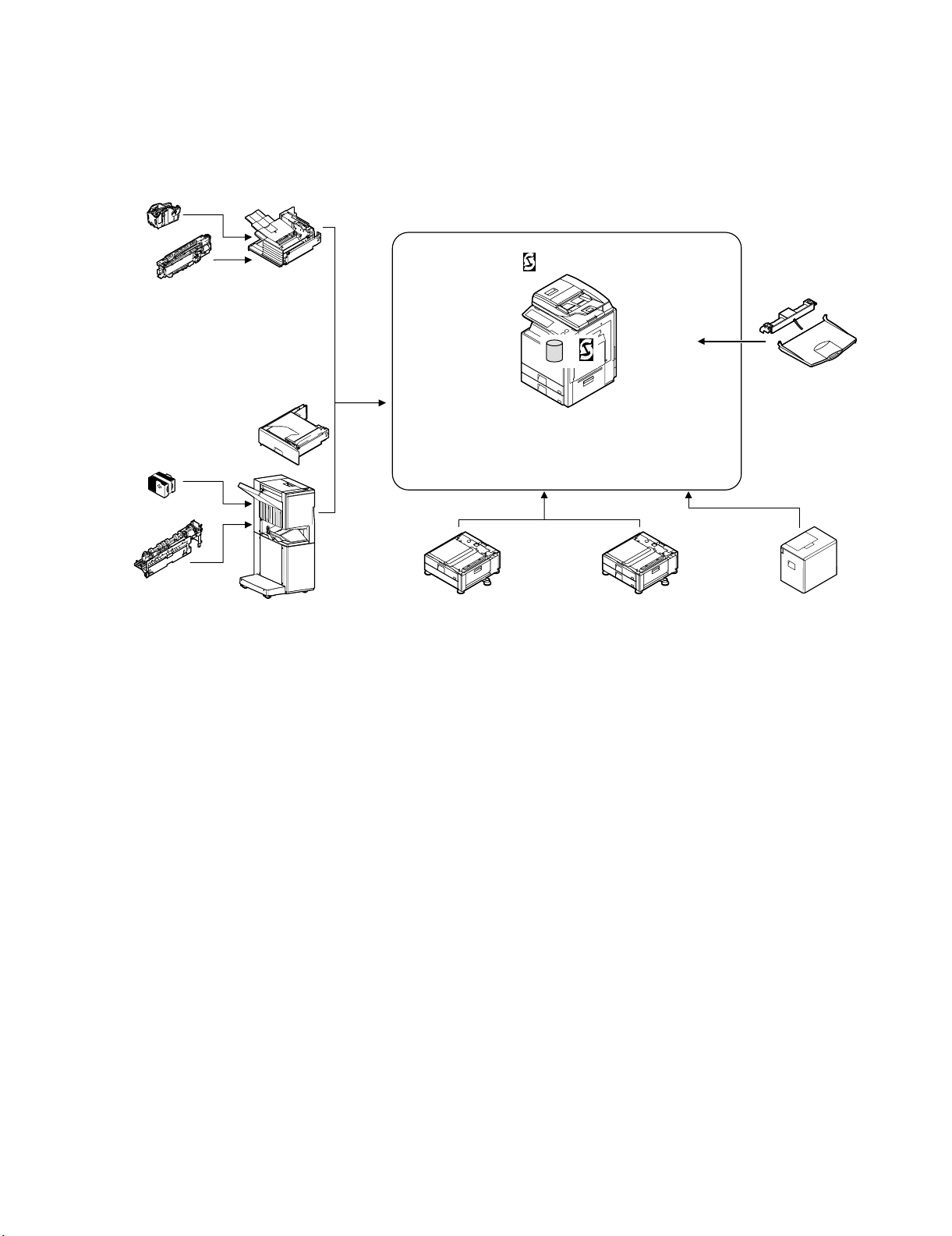
[1] PRODUCT OUTLINE
This model is the document feed unit which allows scanning duplex
document surfaces at the same time. It is installed to the digital
copier machine. It scans duplex document surfaces at the same
time and transport it automatically to make continuous copying.
Service Manual
Staple cartridge
(Approx. 5000 x 3)
(MX-SCX1)
Punch module
●
2-hole (MX-PNX1A)
●
3-hole (MX-PNX1B)
●
4-hole (MX-PNX1C)
●
4-hole (broad space)
Staple cartridge
(Approx. 5000 x 3)
(AR-SC2)
Punch module
●
2-hole (AR-PN1A)
●
3-hole (AR-PN1B)
●
4-hole (AR-PN1C)
●
4-hole (broad space)
(AR-PN1D)
(MX-PNX1D)
Finisher
(MX-FNX1)
Paper pass unit
(MX-RBX1)
Saddle stitch finisher
(MX-FNX2)
Stand/1x500 sheet
paper drawer
(MX-DEX3)
DSPF
HDD
Copier/Printer
/Scanner model
(MX-3501N)
(MX-4501N)
Stand/2x500 sheet
paper drawer
(MX-DEX4)
Exit tray unit
(MX-TRX2)
Large capacity tray
(MX-LCX1)
MX3501N PRODUCT OUTLINE 1 – 1
Page 3

MX3501N
[2] SPECIFICATIONS
Form DSPF (Duplex single pass feeder)
Scan speed Monochrome (A4/8.5 x 11) Color (A4/8.5 x 11)
Copy 1-sided: 45 sheets/minute (600 x 300dpi, 1bit)
Fax 1-sided: 60 sheets/minute (200 x 200dpi, 1bit)
Scanner 1-sided: 60 sheets/minute (200 x 200dpi, 1bit)
Internet Fax 1-sided: 60 sheets/minute (200 x 200 dpi, 1bit)
Document standard
location
Document sizes Inch type-1: 11 x 17, 8.5 x 14, 8.5 x 11, 8.5 x 11R, 8.5 x 5.5, A4, A3
Document weights 1-side:
Document carrying
capacity
Types of document that
may not be transported
Paper detection Yes
Paper detection size Auto detection (Switching one type of detection unit through system setting)
Paper feeding direction Right hand feeding
Document inversion No
Simultaneous doublesided scanning
2-sided: 60 pages/minute (600 x 300dpi, 1bit)
2-sided: 60 pages/minute (200 x 200dpi, 1bit)
2-sided: 60 pages/minute (200 x 200dpi, 1bit)
2-sided: 60 pages/minute (200 x 200 dpi, 1bit)
Center standard (Rear one-side standard for random feeding)
Inch type-2: 11 x 17, 8.5 x 13, 8.5 x 11, 8.5 x 11R, 8.5 x 5.5, A4, A3
AB type-1: A3, B4, A4, A4R, B5, B5R, A5, 8.5 x 11, 8.5 x 14, 11 x 17
AB type-2: A3, B4, A4, A4R, B5, B5R, A5, 8.5 x 11, 216 x 330, 11 x 17
AB type-3: 8K, A4, A4R, B4, 16K, 16KR, A5, 8.5 x 11, 216 x 330, 11 x 17
Long paper: 800mm (Monochrome 2 levels only)
Mixed feeding (same type / same width) possible
Random feeding (feeding of different types / different widths)
Only the following combinations of 2 size types are allowed: A3 and B4; B4 and A4R; A4 and B5; B5 and A5; and 11-inch and 8.5-inch.
Thin paper: 35 – 49g/m
Plain paper: 50 – 128g/m
2-side: 50 – 105 g/m
Maximum: 150 sheets (80g/m
The following documents are NOT allowed:
OHP, second original drawing, tracing paper, carbon paper, thermal paper, wrinkled / broken / torn document, document with cuts and
pastes, documents printed by an ink ribbon, and perforated document except 2-punched / 3-punched (Perforated document by punch
unit is allowed.)
Inch-1: 11 x 17, 8.5 x 14, 8.5 x 11, 8.5 x 11R, 5.5 x 8.5, A4, A3
Inch-2: 11 x 17, 8.5 x 13, 8.5 x 11, 8.5 x 11R, 5.5 x 8.5, A4, A3
AB-1: A3, B4, A4, A4R, B5, B5R, A5, 8.5 x 11, 8.5 x 14, 216 x 330, 11 x 17
AB-2: A3, B4, A4, A4R, B5, B5R, A5, 8.5 x 11, 216 x 330, 11 x 17
AB-3: 8K, B4, A4, A4R, 16K, 16KR, A5, 8.5 x 11, 216 x 330, A3
Allowed
2
(9 – 13 lbs)
2
(13 – 34 lbs)
2
(13 – 28 lbs)
2
, 21lbs), or Maximum: 19.5 mm, 3/4 inch or less
Service Manual
1-sided: 35 sheets/minute (600 x 600dpi, 4bit)
2-sided: 35 pages/minute (600 x 600dpi, 4bit)
N/A
1-sided: 35 sheets/minute (200 x 200dpi, 8bit)
2-sided: 35 pages/minute (200 x 200dpi, 8bit)
N/A
MX3501N SPECIFICATIONS 2 – 1
Page 4

MX3501N
[3] EXTERNAL VIEW AND INTERNAL STRUCTURE
Service Manual
1. Identification of each section and functions
A. Internal structure
3
9
No. Name Function/ Operation
1 Pickup roller Picks up a document and feeds it to the paper feed roller.
2 Paper feed roller Performs the paper feed operation of documents.
3 Separation roller Separate a document to prevent against double-feed.
4 No. 1 resist roller (Drive) Performs resist of document transport.
5 No. 1 resist roller (Idle) Applied a pressure to paper and the resist roller, and provides transport power of the resist roller to paper.
6 Transport roller 1 (Drive) Transports paper from No. 1 resist roller to No. 2 resist roller.
7 Transport roller 1 (Idle) Applied a pressure to paper and the transport roller, and provides the transport power of the transport roller to paper.
8 No. 2 resist roller (Drive) Make synchronization between the lead edge of a document and the scan start position.
9 No. 2 resist roller (Idle) Applies a pressure to paper and the resist roller, and provides transport power of the resist roller to paper.
10 Platen roller Applies a pressure to paper to prevent against fluctuations on operation of paper.
11 Transport roller 2 (Drive) Transports paper from the platen roller to the transport roller 3.
12 Transport roller 2 (Idle) Applies a pressure to paper and the transport roller and provides transport power of the transport roller to paper.
13 Transport roller 3 (Drive) Transports paper from the transport roller 2 to the paper exit roller.
14 Transport roller 3 (Idle) Applies a pressure to paper and the transport roller and provides transport power of the transport roller to paper.
15 Paper exit roller (Drive) Discharges paper.
16 Paper exit roller (Idle) Applies a pressure to paper and the paper exit roller and provides transport power of the paper exit roller to paper.
10 12 14 168 11 13 15
1257 46
MX3501N EXTERNAL VIEW AND INTERNAL STRUCTURE 3 – 1
Page 5

B. Sensors, switches
2
3 7 8 91
54 6
10
11
4
12
13
15
7
8
9
11 12
13 15
1410 16 17
1
3
2
6
5
14
16
17
Signal
No.
name
1 SPPD2 DSPF paper pass sensor 2 Transmission type Detects pass of the paper. L when paper is detected.
2 SPPD1 DSPF paper pass sensor 1 Transmission type Detects pass of the paper. L when paper is detected.
3 SCOV DSPF upper door open/close sensor Transmission type Detects open/close of the upper door. L when the upper door is open.
4 SPRDMD DSPF document random sensor Transmission type Detects the paper size in random paper feed. L when paper is detected.
5 STUD DSPF paper feed tray upper limit
6 SPED1 DSPF document upper limit sensor Transmission type Detects the upper limit of the DSPF document. L when paper is detected.
7 SPWS DSPF document width sensor Volume resistor Detects the document width of the paper feed
8 SPLS1 DSPF document length detection
9 SPLS2 DSPF document length detection
10 SPPD3 DSPF paper pass sensor 3 Transmission type Detects pass of the paper. L when paper is detected.
11 SPPD4 DSPF paper pass sensor 4 Transmission type Detects pass of the paper. L when paper is detected.
12 SOCD DSPF open/close sensor Transmission type Detects open/close of the DSPF unit. L when the DSPF unit is open.
13 SLCOV DSPF lower door open/close sensor Micro switch Detects open/close of the lower door. L when the lower door is open.
14 SPPD5 DSPF paper pass sensor 5 Transmission type Detects pass of the paper. L when paper is detected.
15 SPOD DSPF paper exit sensor Transmission type Detects paper exit of the document. L when paper is detected.
16 SPED2 DSPF document empty sensor Transmission type Detects document empty in the paper feed
17 STLD DSPF paper feed tray lower limit
sensor
short sensor
long sensor
sensor
Name Type Function/Operation Active condition
Transmission type Detects the upper limit of the paper feed tray. L when the upper limit of the
tray upper.
Transmission type Detects the document length of the paper feed
tray upper.
Transmission type Detects the document length of the paper feed
tray upper.
tray.
Transmission type Detects the lower limit of the paper feed tray. H when the lower limit of the
MX3501N EXTERNAL VIEW AND INTERNAL STRUCTURE 3 – 2
paper feed tray is detected.
—
H when paper is detected.
H when paper is detected.
L when paper is detected.
paper feed tray is detected.
Page 6

C. Motors, clutches, solenoids, PWB and lamps
11
8
10
9
2
6
7
5
1
3
4
15
13
12
14
17
16
No. Signal name Name Type Function/Operation
1 SPUM DSPF paper feed motor Hybrid step motor Drives the rollers, transport rollers and transport rollers in the
2 SPFM DSPF transport motor Hybrid step motor Drives the transport roller.
3 SPOM DSPF paper exit motor PM step motor Drives the paper exit roller.
4 SLUM DSPF lift-up motor PM step motor Lifts up or moves down the paper feed tray.
5 SPFC DSPF paper feed clutch Electromagnetic clutch Controls ON/OFF of the rollers in the paper feed section.
6 STRRC DSPF No.1 resist roller clutch Electromagnetic clutch Controls ON/OFF of No. 1 resist roller.
7 STRRBC DSPF No.1 resist roller brake clutch Electromagnetic clutch Performs braking of No. 1 resist roller.
8 STRC DSPF transport roller clutch Electromagnetic clutch Controls ON/OFF of the transport roller 1.
9 SRRC DSPF No.2 resist roller clutch Electromagnetic clutch Controls ON/OFF of No. 2 resist roller.
10 SRRBC DSPF No.2 resist roller brake clutch Electromagnetic clutch Performs braking of No. 2 resist roller.
11 SPFFAN DSPF cooling fan motor DC brush-less motor Cools the motors and the clutches.
12 — DSPF control PWB — Control PWB for DSPF
13 — DSPF flash PWB — Program ROM PWB for DSPF
14 — DSPF driver PWB — Driver PWB for DSPF
15 — DSPF CCD PWB — Scans document images.
16 — DSPF CL inverter PWB — Drives the copy lamp.
17 DSPF COPY LUMP DSPF copy lamp Xenon lamp Radiates light onto a document to allow the CCD to scan
paper feed section.
document images.
MX3501N EXTERNAL VIEW AND INTERNAL STRUCTURE 3 – 3
Page 7

SPWS
SPLS1
SPLS2
MX3501N
[4] OPERATIONAL DESCRIPTIONS
Service Manual
1. Document size detection
Size detection on the document tray
The document size is detected by the DSPF document width sensor (SPWS), and the document length is detected by the DSPF document
length sensors (SPLS1, SPLS2). The document size is judged from the document width and the document length as shown in the table below.
When, however, documents of different sizes are mixed and set on the document tray, the largest size is detected.
Document size
Document length sensor
SPLS1 SPLS2
AB series A5 OFF OFF
B5 OFF OFF
11" x 8.5" OFF OFF
A4 OFF OFF
B5R ON OFF
A4R ON OFF
8.5" x 13" ON ON
B4 ON ON
A3 ON ON
11" x 17" ON ON
Inch series 8.5" x 5.5" OFF OFF
11" x 8.5" OFF OFF
A4 OFF OFF
11" x 8.5"R ON OFF
8.5" x 13" ON ON
8.5" x 14" ON ON
A3 ON ON
11" x 17" ON ON
2. Timing chart
To increase the document replacement speed, pre-feed of the second and the later documents is performed for documents of A4/Letter or
smaller sizes. Therefore, a clutch is provided for each transport roller to perform individual control.
An electromagnetic brake is provided for each transport roller in order to reduce loads to the motor in comparison with a mechanical brake.
Transport speed 314mm/s Letter single-surface transport
SPFFAN
DSPF cooling fan motor
SPUM
DSPF paper feed motor
SPFM
DSPF transport motor
SPFC
DSPF paper feed clutch
SPFC
DSPF paper feed clutch
STRRC
DSPF No.1 resist roller clutch
STRRBC
DSPF No.1 resist roller brake clutch
SPRDMD
DSPF random sensor 1
SPPD1
DSPF paper pass sensor 1
SPPD2
DSPF paper pass sensor 2
STRC
DSPF transport roller clutch
SPPD3
DSPF paper pass sensor 3
SRRC
DSPF No.2 resist roller clutch
SRRBC
DSPF No.2 resist roller brake clutch
SPPD4
DSPF paper pass sensor 4
SPPD5
DSPF paper pass sensor 5
OC scanner scanning
Built-in scanner scanning
SPOD
DSPF paper exit sensor
SPOM
DSPF paper exit motor
Copy key ON
Timer from ON
Timer from ON
12.3mm
37.6mm
11.8mm
39.3mm
ON simultaneously with print start of each motor
OFF at 500ms after SPCD OFF of the last paper
ON simultaneously with SPPD2_ON
OFF at 69.4ms after SPPD2_OFF
ON at 12.3mm - 10ms (29ms) after SPPD3 ON
(SIM adjustment)
OFF at 11.8mm (38ms) after SPPD3 OFF
ON simultaneously with SPPD3 ON
OFF at 10ms before SRRC ON
Scanning start at 37.6mm (120ms) from
SPPD4 ON (SIM adjustment)
Scanning start at 39.3mm (125ms) from
SPPD5 ON (SIM adjustment)
Reduces the speed simultaneously with SPOD OFF,
reduces the speed up to 1855PPS in 15.7mm
Drives for 15mm and returns to 3709PPS in 15.7mm.
(Common to each paper size)
MX3501N OPERATIONAL DESCRIPTIONS 4 – 1
Page 8
MX3501N
[5] DISASSEMBLY AND
ASSEMBLY
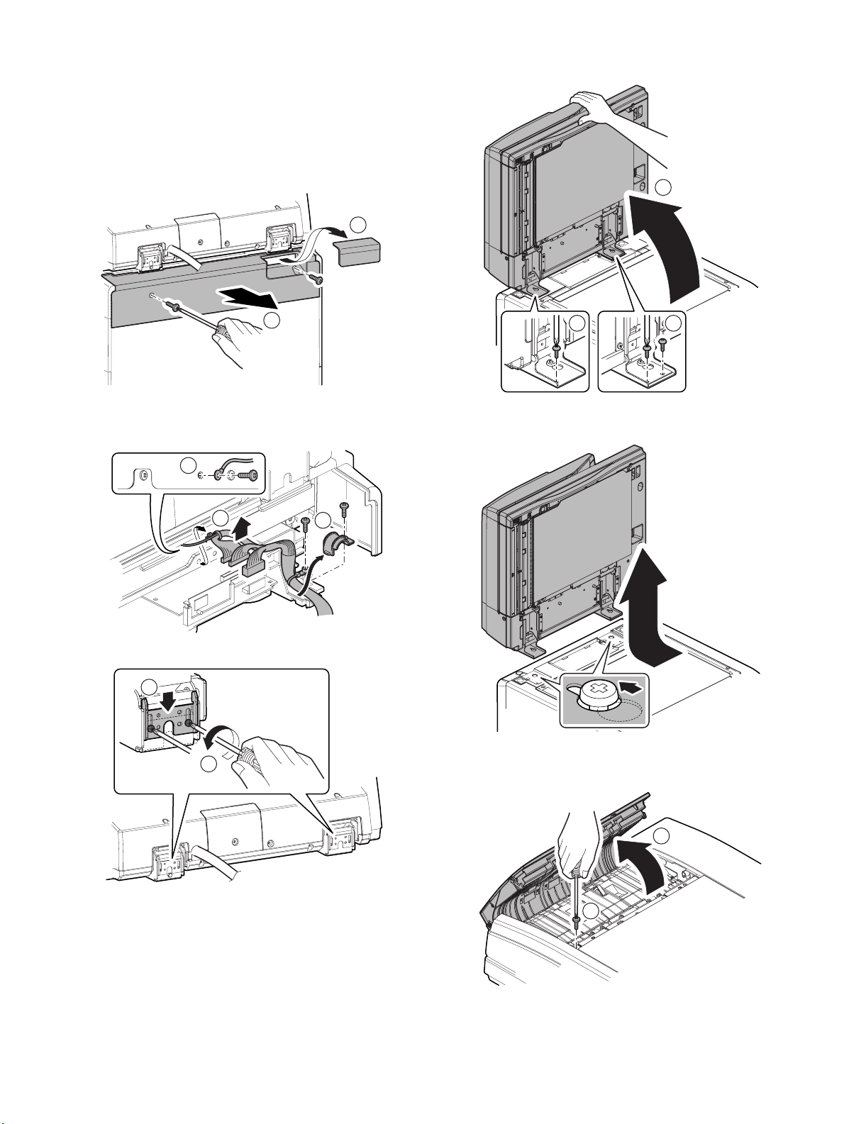
1. Exterior section
A. DSPF unit
1) Remove the upper cabinet rear cover lid. Remove the screw,
and remove the upper cabinet rear cover.
1
4) Open the DSPF unit to put it straight up, and remove the
Service Manual
screw.
1
2
2) Remove the screw, and remove the earth line. Disconnect the
connector, and remove the snap band. Remove the screw, and
remove the locking band and the interface harness cover.
1
2
3) Loosen the screw, and lower the angle adjustment plate.
2
3
22
5) Slide the DSPF unit to the rear side, and fit the step screw with
the key hole of the hinge, and lift it up to remove.
1
MX3501N DISASSEMBLY AND ASSEMBLY 5 – 1
(1) Front cabinet
1) Open the upper door, and remove the screw.
1
2
Page 9

2) Remove the pawl, and remove the front cabinet.
2
(4) Upper door
1) Remove the front cabinet. (Refer to "1. Exterior section - A.
DSPF unit - (1) Front cabinet.")
2) Remove the spring. Remove the pawl. Remove the pressure
3
release axis holder. Remove the screw. Remove the pressure
release link lever.
4
1
(2) Rear cabinet
1) Open the upper door. Remove the screw. Remove the pawl.
Remove the rear cabinet.
2
1
4
1
3
3) Remove the resin E-ring, and remove the upper door.
1
4
2
(3) Paper feed cover
1) Open the upper door. Remove the screw. Remove the paper
feed cover.
2
3
2. Paper feed section
A. Paper feed tray unit
1) Remove the front cabinet. (Refer to "1. Exterior section - A.
DSPF unit - (1) Front cabinet.")
2) Remove the rear cabinet. (Refer to "1. Exterior section - A.
DSPF unit - (2) Rear cabinet.")
3) Disconnect the connector. Remove the screw, and remove the
paper feed tray unit.
1
2
MX3501N DISASSEMBLY AND ASSEMBLY 5 – 2
Page 10

(1) DSPF document length detection short sensor
1
2
(2) DSPF document length detection long sensor
1) Remove the front cabinet. (Refer to "1. Exterior section - A.
DSPF unit - (1) Front cabinet.")
2) Remove the rear cabinet. (Refer to "1. Exterior section - A.
DSPF unit - (2) Rear cabinet.")
3) Remove the paper feed tray unit. (Refer to "2. Paper feed section - A. Paper feed tray unit.")
4) Remove the screw, and remove the paper feed tray lower.
5) Disconnect the connector, and remove the DSPF document
length detection short sensor (a) and the DSPF document
length detection long sensor (b).
5) Remove the screw, and remove the rotation tray shaft.
Remove the paper feed rotation tray.
6) Disconnect the connector. Remove the pawl, and remove the
DSPF document width sensor.
a
b
(3) DSPF document width sensor
1) Remove the front cabinet. (Refer to "1. Exterior section - A.
DSPF unit - (1) Front cabinet.")
2) Remove the rear cabinet. (Refer to "1. Exterior section - A.
DSPF unit - (2) Rear cabinet.")
3) Remove the paper feed tray unit. (Refer to "2. Paper feed section - A. Paper feed tray unit.")
4) Remove the screw, and remove the paper feed tray lower. Disconnect the connector.
2
1
B. Paper feed unit
1) Remove the front cabinet. (Refer to "1. Exterior section - A.
DSPF unit - (1) Front cabinet.")
2) Remove the rear cabinet. (Refer to "1. Exterior section - A.
DSPF unit - (2) Rear cabinet.")
3) Remove the paper feed cover. (Refer to "1. Exterior section A. DSPF unit - (3) Paper feed cover.")
4) Disconnect the connector. Open the wire saddle. Remove the
snap band.
MX3501N DISASSEMBLY AND ASSEMBLY 5 – 3
Page 11
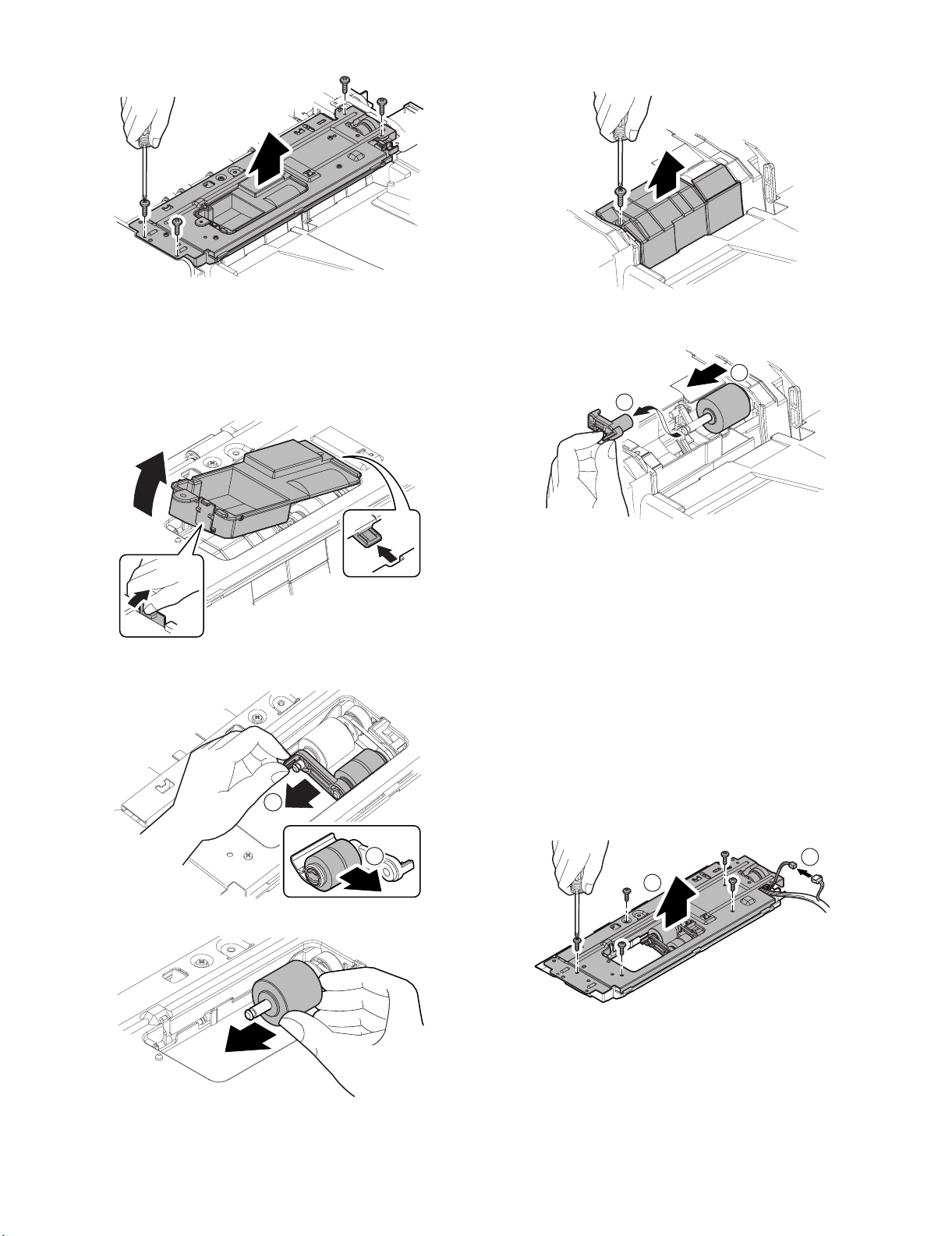
5) Remove the screw, and remove the paper feed unit.
5) Remove the screw, and remove the paper feed PG lower
cover.
(1) Pickup roller
(2) Paper feed roller
(3) Separation roller
1) Remove the paper feed cover. (Refer to "1. Exterior section A. DSPF unit - (3) Paper feed cover.")
2) Remove the pawl, and remove the paper feed PG upper cover.
3) Remove the pawl. Remove the pickup roller holder. Remove
the pickup roller from the pickup roller holder.
1
6) Disengage the pawl, and remove the reverse pressure release
lever. Remove the separation roller.
2
1
(4) DSPF paper feed tray upper limit sensor
(5) DSPF document upper limit sensor
(6) DSPF upper door open/close sensor
(7) DSPF paper pass sensor 1
(8) DSPF document random sensor
1) Remove the front cabinet. (Refer to "1. Exterior section - A.
DSPF unit - (1) Front cabinet.")
2) Remove the rear cabinet. (Refer to "1. Exterior section - A.
DSPF unit - (2) Rear cabinet.")
3) Remove the paper feed cover. (Refer to "1. Exterior section A. DSPF unit - (3) Paper feed cover.")
4) Remove the paper feed unit. (Refer to "2. Paper feed section B. Paper feed unit.")
5) Disconnect the connector. Remove the screw, and remove the
paper feed PG upper supporting plate.
4) Remove the paper feed roller.
2
MX3501N DISASSEMBLY AND ASSEMBLY 5 – 4
1
2
Page 12

6) Disconnect the connector, and remove the DSPF paper feed
tray upper limit sensor (a), the DSPF document upper limit
sensor (b), the DSPF upper door open/close sensor (c), the
DSPF paper pass sensor 1 (d), and the DSPF document random sensor (e).
c
d
7) Remove the E-ring and the bearing. Lift the paper feed roller
shaft diagonally, and remove the DSPF paper feed clutch.
* When assembling, check to insure that the clutch rotation stop-
per is engaged with the plate.
e
a
b
(9) DSPF paper feed clutch
1) Remove the front cabinet. (Refer to "1. Exterior section - A.
DSPF unit - (1) Front cabinet.")
2) Remove the rear cabinet. (Refer to "1. Exterior section - A.
DSPF unit - (2) Rear cabinet.")
3) Remove the paper feed cover. (Refer to "1. Exterior section A. DSPF unit - (3) Paper feed cover.")
4) Remove the paper feed unit. (Refer to "2. Paper feed section B. Paper feed unit.")
5) Remove the pawl, and remove the paper feed PG upper cover.
3
2
1
C. Others
(1) Torque limiter
1) Remove the front cabinet. (Refer to "1. Exterior section - A.
DSPF unit - (1) Front cabinet.")
2) Remove the rear cabinet. (Refer to "1. Exterior section - A.
DSPF unit - (2) Rear cabinet.")
3) Remove the paper feed unit. (Refer to "2. Paper feed section B. Paper feed unit.")
4) Remove the DSPF No.1 resist roller brake clutch and remove
the DSPF No.1 resist roller clutch. (Refer to "3. Upper transport section - A. DSPF No.1 resist roller brake clutch, B. DSPF
No.1 resist roller clutch.")
5) Remove the drive unit. (Refer to "7. Drive section - A. Drive
unit.")
6) Remove the resin E-ring, and remove the No.1 resist roller
(idle).
6) Disconnect the connector. Remove the screw, and remove the
paper feed PG upper supporting plate.
1
2
2
1
7) Remove the screw. Lift the paper feed rotation tray, and
remove the paper feed PG lower.
2
1
MX3501N DISASSEMBLY AND ASSEMBLY 5 – 5
Page 13

8) Remove the screw, and remove the separation roller supporting plate and the bearing. Remove the roller shaft, and remove
the torque limiter.
2
1
3
(2) DSPF paper feed tray lower limit sensor
(3) DSPF document empty sensor
1) Remove the front cabinet. (Refer to "1. Exterior section - A.
DSPF unit - (1) Front cabinet.")
2) Remove the rear cabinet. (Refer to "1. Exterior section - A.
DSPF unit - (2) Rear cabinet.")
3) Remove the paper feed tray unit. (Refer to "2. Paper feed section - A. Paper feed tray unit.")
4) Disconnect the connector, and remove the DSPF paper feed
tray lower limit sensor (a) and the DSPF document empty sensor (b).
b
3. Upper transport section
A. DSPF No.1 resist roller brake clutch
B. DSPF No.1 resist roller clutch
1) Remove the rear cabinet. (Refer to "1. Exterior section - A.
DSPF unit - (2) Rear cabinet.")
2) Disconnect the connector. Remove the resin E-ring. Remove
the DSPF No.1 resist roller brake clutch (a) and the DSPF
No.1 resist roller clutch (b).
* When assembling, check to insure that the clutch rotation stop-
per is engaged with the plate.
b
a
2
3
1
C. DSPF transport roller clutch
1) Remove the rear cabinet. (Refer to "1. Exterior section - A.
DSPF unit - (2) Rear cabinet.")
2) Disconnect the connector, and remove the snap band.
Remove the resin E-ring, and remove the DSPF transport
roller clutch.
* When assembling, check to insure that the clutch rotation stop-
per is engaged with the plate.
a
3
2
1
MX3501N DISASSEMBLY AND ASSEMBLY 5 – 6
Page 14

D. No.1 resist roller (Drive)
1) Remove the front cabinet. (Refer to "1. Exterior section - A.
DSPF unit - (1) Front cabinet.")
2) Remove the rear cabinet. (Refer to "1. Exterior section - A.
DSPF unit - (2) Rear cabinet.")
3) Remove the paper feed unit. (Refer to "2. Paper feed section B. Paper feed unit.")
4) Remove the DSPF No.1 resist roller brake clutch and remove
the DSPF No.1 resist roller clutch. (Refer to "3. Upper transport section - A. DSPF No.1 resist roller brake clutch, B. DSPF
No.1 resist roller clutch.")
5) Remove the resin E-ring, and remove the No.1 resist roller
(idle).
2
1
8) Remove the E-ring and the bearing from the No.1 resist roller
(drive).
E. DSPF paper pass sensor 2
F. Transport roller 1 (drive)
1) Remove the front cabinet. (Refer to "1. Exterior section - A.
DSPF unit - (1) Front cabinet.")
2) Remove the rear cabinet. (Refer to "1. Exterior section - A.
DSPF unit - (2) Rear cabinet.")
3) Remove the screw, and remove the transport PG upper.
6) Remove the screw, lift the paper feed rotation tray, and remove
the paper feed PG lower.
2
1
7) Remove the resin E-ring and the bearing, and remove the
No.1 resist roller (drive).
2
4) Disconnect the connector, and remove the DSPF paper pass
sensor 2.
1
MX3501N DISASSEMBLY AND ASSEMBLY 5 – 7
Page 15

5) Remove the DSPF transport roller clutch. (Refer to "3. Upper
transport section - C. DSPF transport roller clutch.")
6) Remove the E-ring, the washer, the spring, the collar, the polyslider, and the bearing. Remove the belt, the pulley, and the
bearing, and remove the transport roller 1 (drive).
1
C. DSPF No.2 resist roller brake clutch
D. DSPF No.2 resist roller clutch
1) Remove the rear cabinet. (Refer to "1. Exterior section - A.
DSPF unit - (2) Rear cabinet.")
2) Disconnect the connector. Remove the resin E-ring and
remove the DSPF No.2 resist roller brake clutch (a) and the
DSPF No.2 resist roller clutch (b).
* When assembling, check to insure that the clutch rotation stop-
per is engaged with the plate.
b
2
7) Remove the E-ring and the bearing from the transport roller 1
(drive).
1
4. Lower transport section
A. Platen roller
B. No.1 scanning plate
1) Open the DSPF unit, and clean the platen roller and the No.1
scanning plate.
1
a
3
2
E. DSPF paper pass sensor 3
F. DSPF paper pass sensor 4
G. No.2 resist roller (Drive)
1) Remove the front cabinet. (Refer to "1. Exterior section - A.
DSPF unit - (1) Front cabinet.")
2) Remove the rear cabinet. (Refer to "1. Exterior section - A.
DSPF unit - (2) Rear cabinet.")
3) Remove the upper door. (Refer to "1. Exterior section - A.
DSPF unit - (3) Upper door.")
4) Remove the screw, and remove the transport PG upper.
MX3501N DISASSEMBLY AND ASSEMBLY 5 – 8
Page 16

5) Loosen the screw, and lower the angle adjustment plate. Open
the DSPF unit.
2
10) Remove the screw and the connector, and remove the DSPF
paper pass sensor 3.
1
1
3
6) Remove the screw, and remove the left rear lower cabinet.
7) Remove the resin E-ring, and remove the PS knob.
2
1
2
11) Remove the screw, and remove the lift-up PG.
12) Remove the screw, and remove the spring. Remove the belt,
the pawl, and the platen roller.
2
8) Remove the screw, and remove the PS outer PG.
9) Remove the screw, and remove the PS front PG.
1
4
3
2
13) Disconnect the connector and remove the screw. Remove the
DSPF paper pass sensor 4.
MX3501N DISASSEMBLY AND ASSEMBLY 5 – 9
Page 17

14) Remove the DSPF No.2 resist roller brake clutch and the
DSPF No.2 resist roller clutch. (Refer to "4. Lower transport
section - C. DSPF No.2 resist roller brake clutch, D. DSPF
No.2 resist roller clutch.")
15) Remove the DSPF cooling fan motor. (Refer to "7. Drive section - C. Others - (1) DSPF cooling fan motor.")
16) Remove the E-ring, the washer, the spring, the collar, the polyslider, and the bearing.
17) Loosen the screw. Loosen the belt tension. Tighten the screw.
Slide the roller. Remove the pulley, the E-ring, and the bearing.
Remove the No.2 resist roller (drive).
1
5) Remove the screw, and remove the lift-up PG.
6) Remove the screw, and remove the intersecting point plate.
Remove the lower door.
2
1
3
2
H. DSPF paper pass sensor 5
I. Transport roller 2 (Drive)
1) Remove the front cabinet. (Refer to "1. Exterior section - A.
DSPF unit - (1) Front cabinet.")
2) Remove the rear cabinet. (Refer to "1. Exterior section - A.
DSPF unit - (2) Rear cabinet.")
3) Remove the OC mat. (Refer to "8. Others - A. OC mat.")
4) Loosen the screw, and lower the angle adjustment plate. Open
the DSPF unit.
2
3
7) Open the lower door. Remove the screw. Remove the transport PG lower. Disconnect the connector.
2
3
4
8) Disconnect the connector, and remove the DSPF paper pass
sensor 5.
1
1
MX3501N DISASSEMBLY AND ASSEMBLY 5 – 10
3
Page 18

9) Remove the DSPF No.1 resist roller brake clutch and the
DSPF No.1 resist roller clutch. (Refer "3. Upper transport section - A. DSPF No.1 resist roller brake clutch - B. DSPF No.1
resist roller clutch.")
10) Remove the drive unit. (Refer to "7. Drive section - A. Drive
unit.")
11) Disconnect the connector. Remove the screw, and remove the
control PWB unit.
1
3
J. Transport roller 3 (drive)
1) Remove the front cabinet. (Refer to "1. Exterior section - A.
DSPF unit - (1) Front cabinet.")
2) Remove the rear cabinet. (Refer to "1. Exterior section - A.
DSPF unit - (2) Rear cabinet.")
3) Remove the paper feed unit. (Refer to "2. Paper feed section B. Paper feed unit.")
4) Remove the DSPF No.1 resist roller brake clutch and the
DSPF No.1 resist roller clutch. (Refer to "3. Upper transport
section - A. DSPF No.1 resist roller brake clutch, B. DSPF
No.1 resist roller clutch.")
5) Remove the drive unit. (Refer to "7. Drive section - A. Drive
unit.")
6) Remove the resin E-ring, and remove the No.1 resist roller
(idle).
1
2
2
12) Loosen the screw, and loosen the belt tension. Tighten the
screw. Remove the belt. Remove the E-ring and the pulley.
1
2
3
13) Remove the resin E-ring. Slide the bearing. Remove the transport roller 2 (drive). Remove the bearing, the E-ring, and the
spring pin from the transport roller 2 (drive).
2
3
2
1
7) Remove the screw. Lift the paper feed rotation tray, and
remove the paper feed PG lower.
2
1
8) Disconnect the connector. Remove the screw, and remove the
control PWB unit.
1
3
3
1
1
2
2
MX3501N DISASSEMBLY AND ASSEMBLY 5 – 11
Page 19

9) Loosen the screw, and loosen the belt tension. Tighten the
screw. Remove the belt.
5) Remove the screw, and remove the intersecting point plate.
Remove the lower door.
1
2
10) Remove the resin E-ring and the bearing. Remove the transport roller 3 (drive). Remove the E-ring, the pulley, the spring
pin, and the bearing from the transport roller 3 (drive).
1
2
3
2
1
3
6) Remove the screw, and remove the intersecting point plate.
Remove the white reference plate.
1
5. Optical section
A. Lamp unit
1) Remove the front cabinet. (Refer to "1. Exterior section - A.
DSPF unit - (1) Front cabinet.")
2) Remove the rear cabinet. (Refer to "1. Exterior section - A.
DSPF unit - (2) Rear cabinet.")
3) Remove the OC mat. (Refer to "8. Others - A. OC mat.")
4) Remove the connector from the DSPF CL inverter PWB.
2
7) Remove the screw, and remove the scanning section cover.
Remove the screw, and remove the lamp unit.
3
4
2
1
MX3501N DISASSEMBLY AND ASSEMBLY 5 – 12
Page 20

(1) Scanning glass
(2) DSPF copy lamp
(3) Reflector
1) Open the DSPF unit, and open the lower door.
2
2) Remove the cleaner.
4) Remove the front cabinet. (Refer to "1. Exterior section - A.
DSPF unit - (1) Front cabinet.")
5) Remove the rear cabinet. (Refer to "1. Exterior section - A.
DSPF unit - (2) Rear cabinet.")
6) Remove the OC mat. (Refer to "8. Others - A. OC mat.")
7) Remove the lamp unit. (Refer to "5. Optical section - A. Lamp
unit.")
1
8) Remove the screw, and remove the DSPF copy lamp.
9) Clean the scanning glass (back surface).
3) Use the cleaner to clean the scanning glass (surface).
10) Remove the screw, and remove the reflector.
MX3501N DISASSEMBLY AND ASSEMBLY 5 – 13
Page 21

B. Optical unit
1) Remove the front cabinet. (Refer to "1. Exterior section - A.
DSPF unit - (1) Front cabinet.")
2) Remove the rear cabinet. (Refer to "1. Exterior section - A.
DSPF unit - (2) Rear cabinet.")
3) Remove the upper door. (Refer to "1. Exterior section - A.
DSPF unit - (3) Upper door.")
4) Remove the OC mat. (Refer to "8. Others - A. OC mat.")
5) Remove the lamp unit. (Refer to "5. Optical section - A. Lamp
unit.")
6) Remove the screw, and remove the transport PG upper.
(1) Lens
(2) CCD
1) Remove the front cabinet. (Refer to "1. Exterior section - A.
DSPF unit - (1) Front cabinet.")
2) Remove the rear cabinet. (Refer to "1. Exterior section - A.
DSPF unit - (2) Rear cabinet.")
3) Remove the upper door. (Refer to "1. Exterior section - A.
DSPF unit - (3) Upper door.")
4) Remove the OC mat. (Refer to "8. Others - A. OC mat.")
5) Remove the lamp unit. (Refer to "5. Optical section - A. Lamp
unit.")
6) Remove the optical unit. (Refer to "5. Optical section - B. Optical unit.")
7) Remove the screw. Remove the pawl. Remove the dust-proof
cover. Remove the screw, and remove the dark box.
7) Remove the screw, and remove the harness cover. Disconnect
the connector.
* When assembling, arrange the harness so that it is placed in
the lower position than the rib height.
1
2
2
8) Remove the step screw, and remove the screw. Remove the
optical fixing plate. Remove the optical unit.
2
3
8) Remove the pawl, and remove the lens cover.
9) Clean the lens (a) and the CCD (b).
b
1
a
MX3501N DISASSEMBLY AND ASSEMBLY 5 – 14
Page 22

(3) CCD unit
1) Remove the front cabinet. (Refer to "1. Exterior section - A.
DSPF unit - (1) Front cabinet.")
2) Remove the rear cabinet. (Refer to "1. Exterior section - A.
DSPF unit - (2) Rear cabinet.")
3) Remove the upper door. (Refer to "1. Exterior section - A.
DSPF unit - (3) Upper door.")
4) Remove the OC mat. (Refer to "8. Others - A. OC mat.")
5) Remove the lamp unit. (Refer to "5. Optical section - A. Lamp
unit.")
6) Remove the optical unit. (Refer to "5. Optical section - B. Optical unit.")
7) Remove the screw. Remove the pawl. Remove the dust-proof
cover. Remove the screw, and remove the dark box.
(4) Mirror
1) Remove the front cabinet. (Refer to "1. Exterior section - A.
DSPF unit - (1) Front cabinet.")
2) Remove the rear cabinet. (Refer to "1. Exterior section - A.
DSPF unit - (2) Rear cabinet.")
3) Remove the upper door. (Refer to "1. Exterior section - A.
DSPF unit - (3) Upper door.")
4) Remove the OC mat. (Refer to "8. Others - A. OC mat.")
5) Remove the lamp unit. (Refer to "5. Optical section - A. Lamp
unit.")
6) Remove the optical unit. (Refer to "5. Optical section - B. Optical unit.")
7) Remove the screw, and remove the mirror base cover.
8) Remove the screw, and remove the CCD unit.
8) Clean the mirror.
C. Others
(1) DSPF CL inverter PWB
1) Remove the rear cabinet. (Refer to "1. Exterior section - A.
DSPF unit - (2) Rear cabinet.")
2) Disconnect the connector, and remove the control PWB unit.
1
3
1
MX3501N DISASSEMBLY AND ASSEMBLY 5 – 15
2
2
Page 23

3) Disconnect the connector, and remove the screw. Remove the
inverter PWB guide.
3) Use the cleaner to clean the white reference glass.
4) Remove the screw, and remove the DSPF CL inverter PWB.
(2) White reference glass
1) Open the DSPF unit, and open the lower door.
1
2
2) Remove the cleaner.
6. Paper exit section
A. Discharge brush
1) Remove the front cabinet. (Refer to "1. Exterior section - A.
DSPF unit - (1) Front cabinet.")
2) Remove the rear cabinet. (Refer to "1. Exterior section - A.
DSPF unit - (2) Rear cabinet.")
3) Remove the paper feed tray unit. (Refer to "2. Paper feed section - A. Paper feed tray unit.")
4) Remove the discharge brush.
* When attaching the discharge brush, attach it to the attachment
reference.
B. DSPF paper exit sensor
1) Remove the front cabinet. (Refer to "1. Exterior section - A.
DSPF unit - (1) Front cabinet.")
2) Remove the rear cabinet. (Refer to "1. Exterior section - A.
DSPF unit - (2) Rear cabinet.")
3) Remove the paper feed tray unit. (Refer to "2. Paper feed section - A. Paper feed tray unit.")
4) Disconnect the connector, and remove the DSPF paper exit
sensor.
MX3501N DISASSEMBLY AND ASSEMBLY 5 – 16
Page 24

C. Paper exit roller (drive)
1) Remove the front cabinet. (Refer to "1. Exterior section - A.
DSPF unit - (1) Front cabinet.")
2) Remove the rear cabinet. (Refer to "1. Exterior section - A.
DSPF unit - (2) Rear cabinet.")
3) Remove the paper feed tray unit. (Refer to "2. Paper feed section - A. Paper feed tray unit.")
4) Remove the DSPF No.1 resist roller brake clutch, and remove
the DSPF No.1 resist roller clutch. (Refer to "3. Upper transport section - A. DSPF No.1 resist roller brake clutch, B. DSPF
No.1 resist roller clutch.")
5) Remove the drive unit. (Refer to "7. Drive section - A. Drive
unit.")
6) Remove the resin E-ring, the gear, the bearing, and the paper
exit roller (drive).
4) Remove the screw, and remove the drive unit.
1
2
1
7. Drive section
A. Drive unit
1) Remove the rear cabinet. (Refer to "1. Exterior section - A.
DSPF unit - (2) Rear cabinet.")
2) Remove the DSPF No.1 resist roller brake clutch and the
DSPF No.1 resist roller clutch. (Refer to "3. Upper transport
section - A. DSPF No.1 resist roller brake clutch, B. DSPF
No.1 resist roller clutch.")
3) Disconnect the connector, and open the edge saddle. Remove
the snap band.
(1) DSPF paper feed motor
1) Remove the rear cabinet. (Refer to "1. Exterior section - A.
DSPF unit - (2) Rear cabinet.")
2) Disconnect the connector, and open the edge saddle. Remove
the screw, and remove the DSPF paper feed motor.
(2) DSPF paper exit motor
1) Remove the rear cabinet. (Refer to "1. Exterior section - A.
DSPF unit - (2) Rear cabinet.")
2) Disconnect the connector, and open the edge saddle. Remove
the screw, and remove the DSPF paper exit motor.
MX3501N DISASSEMBLY AND ASSEMBLY 5 – 17
Page 25

(3) DSPF lift-up motor
1) Remove the rear cabinet. (Refer to "1. Exterior section - A.
DSPF unit - (2) Rear cabinet.")
2) Disconnect the connector, and open the edge saddle. Remove
the screw, and remove the DSPF lift-up motor.
B. Drive transport unit
1) Remove the rear cabinet. (Refer to "1. Exterior section - A.
DSPF unit - (2) Rear cabinet.")
2) Remove the DSPF No.1 resist roller brake clutch and the
DSPF No.1 resist roller clutch. (Refer to "3. Upper transport
section - A. DSPF No.1 resist roller brake clutch, B. DSPF
No.1 resist roller clutch.")
3) Remove the DSPF transport roller clutch. (Refer to "3. Upper
transport section - C. DSPF transport roller clutch.")
4) Remove the DSPF cooling fan motor. (Refer to "7. Drive section - C. Others - (1) DSPF cooling fan motor.")
5) Loosen the screw, and loosen the belt tension. Tighten the
screw.
(1) DSPF transport motor
1) Remove the rear cabinet. (Refer to "1. Exterior section - A.
DSPF unit - (2) Rear cabinet.")
2) Loosen the screw, and loosen the belt tension. Tighten the
screw.
3) Disconnect the connector, and remove the screw. Remove the
DSPF transport motor.
6) Remove the screw, and remove the drive transport unit.
C. Others
(1) DSPF cooling fan motor
1) Remove the rear cabinet. (Refer to "1. Exterior section - A.
DSPF unit - (2) Rear cabinet.")
2) Disconnect the connector, and remove the DSPF cooling fan
motor.
MX3501N DISASSEMBLY AND ASSEMBLY 5 – 18
Page 26

8. Others
A. OC mat
1) Open the DSPF unit, and remove the OC mat from the left
edge.
* When assembling, place the OC mat on the document table to fit
with the reference and close the DSPF unit.
C. DSPF lower door open/close sensor
1) Remove the front cabinet. (Refer to "1. Exterior section - A.
DSPF unit - (1) Front cabinet.")
2) Disconnect the connector, and remove the screw. Remove the
lower door open/close sensor holder. Remove the DSPF lower
door open/close sensor from the lower door open/close sensor
holder.
D. DSPF driver PWB
1) Remove the rear cabinet. (Refer to "1. Exterior section - A.
DSPF unit - (2) Rear cabinet.")
2) Disconnect the connector. Remove the screw, and remove the
DSPF driver PWB.
B. DSPF open/close sensor
1) Remove the front cabinet. (Refer to "1. Exterior section - A.
DSPF unit - (1) Front cabinet.")
2) Disconnect the connector and remove the screw. Remove the
open/close sensor holder. Remove the DSPF open/close sensor from the open/close sensor holder.
E. DSPF flash PWB
1) Remove the screw, and remove the ROM cover.
MX3501N DISASSEMBLY AND ASSEMBLY 5 – 19
Page 27

2) Release the lock, and remove the DSPF flash PWB.
2
1
F. DSPF control PWB
1) Remove the rear cabinet. (Refer to "1. Exterior section - A.
DSPF unit - (2) Rear cabinet.")
2) Remove the DSPF flash PWB. (Refer to "8. Others - E. DSPF
flash PWB.")
3) Disconnect the connector, and remove the screw. Remove the
control PWB unit.
1
3
1
2
4) Disconnect the connector, and remove the screw. Remove the
DSPF control PWB.
2
MX3501N DISASSEMBLY AND ASSEMBLY 5 – 20
Page 28

MX3501N
[6] MAINTENANCE
Service Manual
1. Maintenance system table
✕: Check (Clean, replace, or adjust according to necessity.) {: Clean ▲: Replace U: Adjust ✩: Lubricate : Shift the position.
No. Part name When calling
1 Paper feed
section/
2 Pickup roller {{
Transport
3 Separation roller {{
section
4 Torque limiter ✕✕Replacement reference: 100K
5 No. 1 resist roller (Drive) {{
6 Transport roller 1 (Drive) {{
7 No. 2 resist roller (Drive) {{
8 Platen roller {{
9 Transport roller 2 (Drive) {{
10 Transport roller 3 (Drive) {{
11 Paper exit roller (Drive) {{
12 Discharge brush ✕✕
13 No. 1 scanning plate {{
14 No. 2 scanning section, scanning glass {{
15 No. 2 scanning section, white reference glass {{
16 Optical section Lens {{
17 CCD {{
18 Mirror ✕✕
19 Copy lamp {{
20 Reflector {{
21 Drive section Gears (Grease) ✕✕UKOG-0299FCZZ (specified positions)
22 Belts ✕
23 Others OC mat {{
Paper feed roller {{Replacement reference: 100K or 1 year
Main unit
maintenance cycle
Remarks
5
17
18
15
6
7
8
13
9
10
11
12
16
19
20
14
1
4
2
3
23
22
22
21
22
MX3501N MAINTENANCE 6 – 1
Page 29

MX3501N
[7] ADJUSTMENTS
1. Levelness adjustment
This adjustment is needed in the following situations:
* The DSPF section has been disassembled.
* The DSPF unit has been replaced.
1) Close the DSPF unit and check the clearance between the
projections in the front side and the rear side and the SPF
glass holding resin surface.
2) Visually check to insure that the clearance A is 1mm or less
and the clearance B is 0mm (in contact).
4) After adjustments of A and B, check to insure that the projec-
Service Manual
tion on the front right side is in contact with the glass surface of
the main unit.
2. Skew adjustment (front surface mode)
This adjustment is needed in the following situations:
* The DSPF section has been disassembled.
* When replacing the DSPF unit.
* The DSPF unit generates skewed scanned images.
1) Create an adjustment chart by printing in duplex mode the selfprint pattern 71 (grid pattern) specified in Simulation 64-1.
Make sure that the print grid pattern is almost in parallel with
the paper edges, and apply position marks 'A', 'B', 'C' and 'D' to
the leading and trailing edges of the paper for both front and
back sides of the paper.
1mm
A
B
0mm
If the above requirement is not met, do step 3.
3) Turn the height adjustment screw to adjust the DSPF front/rear
frame horizontal level.
L
R
A
Paper pass direction
B
2) Copy the adjustment chart (created in step 1) to A3 (11" x 17")
paper in DSPF duplex mode, and then check the image for
skews (Set in the DSPF feed tray so that the mark on the
adjustment chart is at the edge).
• Check with one of the following methods.
[Check Method 1]
(Front side)
Make sure that the output satisfies the condition: |a-b| ± 1 mm
A
a
B
b
When the front frame side is higher (clearance B is more than
1mm): Turn the height adjustment screw R of the DSPF rear
frame clockwise.
When the rear frame side is higher (clearance A is more than
1mm): Turn the height adjustment screw L of the DSPF rear
frame counterclockwise.
Repeat steps 2 to 3 until an acceptable result is obtained.
MX3501N ADJUSTMENTS 7 – 1
(Back side)
Make sure that the output satisfies the condition: |c-d| ± 1 mm
C
c
D
d
Page 30

[Check Method 2]
Check that the squareness of the main scanning direction
print line for the longitudinal direction of paper is within
1.0mm.
0 - 1.0mm
[When the main scanning direction print line is shifted to the
left]
If a < b, then turn counterclockwise the DSPF skew
adjusting screw.
[When the main scanning direction print line is shifted to the
right]
If a > b, then turn clockwise the DSPF skew adjusting screw.
Repeat steps 2 to 5 until an acceptable result is obtained.
A
If the front surface copy image is as shown above and the
back surface copy is not as shown above, go to the step 3)
of "3. Skew adjustment (Back surface mode)."
If the above requirement is not met for the paper's front side,
then do step 3.
3) Loosen the hinge screws and lower the two attachments.
2
1
4) Open the DSPF and loosen the screw.
3. Skew adjustment (back surface mode)
This adjustment is needed in the following situations:
* The DSPF section has been disassembled.
* When replacing the DSPF unit.
* The DSPF unit generates skewed scanned images.
1) Create an adjustment chart by printing in duplex mode the selfprint pattern 71 (grid pattern) specified in Simulation 64-1.
Make sure that the print grid pattern is almost in parallel with
the paper edges, and apply position marks 'A', 'B', 'C' and 'D' to
the leading and trailing edges of the paper for both front and
back sides of the paper.
A
Paper pass direction
B
2) Copy the adjustment chart (created in step 1) to A3 (11" x 17")
paper in DSPF duplex mode, and then check the image for
skews (Set in the DSPF feed tray so that the mark on the
adjustment chart is at the edge).
• Check with one of the following methods.
[Check Method 1]
(Front side)
Make sure that the output satisfies the condition: |a-b| ± 1 mm
5) Adjust by turning the DSPF skew adjusting screw on the right
side of the DSPF rear frame.
MX3501N ADJUSTMENTS 7 – 2
A
a
(Back side)
Make sure that the output satisfies the condition: |c-d| ± 1 mm
C
c
B
b
D
d
Page 31

[Check Method 2]
Check that the squareness of the main scanning direction
print line for the longitudinal direction of paper is within
1.0mm.
0 - 1.0mm
A
If the back surface copy image is as shown above and the
front surface copy is not as shown above, go to the step 3)
of "2. Skew adjustment (Front surface mode)."
If the back surface copy is not as shown above, perform the
procedures of step 3) or later.
3) Open the upper door, and remove the adjustment cover.
[When the main scanning direction print line is shifted to the
left]
If c < d, turn the DSPF skew adjustment screw A
counterclockwise, or turn the adjustment screw B clockwise.
[When the main scanning direction print line is shifted to the
right]
If c > d, turn the DSPF skew adjustment screw A clockwise,
or turn the adjustment screw B counterclockwise.
* The adjustment screws A and B must be turned in proper
balance. For example, if the trouble is not removed by turning the adjustment screw A 180 degrees clockwise, do not
turn the adjustment screw A furthermore, but turn the adjustment screw B 180 degrees counterclockwise.
Repeat steps 2 to 5 until an acceptable result is obtained.
4. Image focus adjustment (front surface mode)
For details of this adjustment, refer to "[6] ADJUSTMENTS" of the
copier Service Manual (00ZMX3500NS1E).
5. Image focus adjustment (back surface mode)
This adjustment is required in the following cases:
* When the DSPF CCD unit is replaced.
* When the DSPF CCD unit is replaced.
* When the COPY/SCAN/FAX image focus is not properly
adjusted.
* When the DSPF unit is removed.
* When the DSPF unit is replaced.
1) Make a duplex copy in DSPF mode.
2) Make sure that the copied image on the back side of the paper
is satisfactorily focused.
If the image is not satisfactorily focused, do the following
steps.
3) Open the door. Remove the screws, and remove the transport
PG upper.
4) Turn the DSPF skew adjustment screw on the CCD unit to
adjust.
A
B
4) To prevent against shift of the CCD unit optical axis, mark the
CCD unit base as shown below.
MX3501N ADJUSTMENTS 7 – 3
Page 32

5) Loosen the CCD unit fixing screws (4 pcs.).
A4 size
(both sides)
10mm10mm
Paper pass direction
CLOSE
0
A
:
A㧦 50
B㧦 50
C㧦 50
D㧦 50
㧧 CCD(MAIN)
㧧 CCD(SUB)
㧧
SPF(MAIN)
㧧
SPF(SUB)
SIMULATIONNO.48㧙01
MAGNIFICATION AD JUSTMENT
XX
㨇 1㨪99 㨉
O
K
TEST
* Never loosen the screws marked with ✕.
Loosening these screws could possibly change the CCD
unit base optical axis. Once the optical axis has been
changed, it cannot be corrected through on-site adjustments. Solving such a problem requires the replacement of
the entire scanner unit.
6) Slide the CCD unit in the arrow direction (CCD sub scanning
direction) to change the installing position.
When the copy image is longer than the original scale, shift the
CCD unit in the direction B. When the copy image is shorter
than the original scale, shift the CCD unit in the direction A.
One scale of mark-off line corresponds to 0.2%.
At that time, fix the CCD unit so that it is in parallel with the
scale on the front and the rear side of the CCD unit base.
* Fix the CCD unit so that it is in parallel with the line marked
in procedure 4).
* Images are not correctly magnified in the main scanning direc-
tion.
1) On the DSPF original tray, place such an original as illustrated
below.
2) Make a normal duplex copy on A4 paper.
3) Measure the lengths of the copied image (back surface) and
the original image.
original
copy
10
100 150
50
250
200
10
100 150
50
250
200
7) Make a copy and check the copy magnification ratio again.
NOTE: By changing the CCD unit fixing position with the simula-
6. Image magnification in the main
For details of this adjustment, refer to "[6] ADJUSTMENTS" of the
copier Service Manual (00ZMX3500NS1E).
7. Image magnification in the main
This adjustment is required in the following cases:
* The MFP control PWB has been replaced.
* The EEPROM on the MFP control PWB has been replaced.
* The scan control PWB has been replaced.
* The EEPROM on the scan control PWB has been replaced.
* When a U2 trouble occurs.
A
B
If the copy magnification ratio is not in the range of 100 ± 1%,
repeat the procedures of 4) – 6) until the condition is satisfied.
tion 48-1 adjustment value at 50, the copy magnification
ratio is adjusted within the specified range (100 ± 1.0%)
and the specified resolution is obtained based on the optical system structure.
scanning direction adjustment (front
surface mode)
scanning direction adjustment (back
surface mode)
MX3501N ADJUSTMENTS 7 – 4
4) Determine the image magnification factor using the following
formula:
Image magnification factor (%) = Copy dimension/original
dimension x 100
Image magnification factor (%) = 99 / 100 x 100 = 99
If the image magnification factor is within the spec (100±0.8%),
no adjustment is required; otherwise, do the following steps.
5) Enter the simulation 48-1 mode.
1) Select the item corresponding to be adjusted with scroll key.
2) Press [START] key.
3) Enter the image magnification adjustment value with the 10key.
4) Press [START] key.
Pressing the [START] key starts copy operation as well as
applying the adjustment value.
Repeat the above adjustments until an acceptable result is
obtained.
8. Image magnification in the sub
scanning direction adjustment
This adjustment is required in the following cases:
* Images are not correctly magnified in the sub-scanning direction.
* The MFP control PWB has been replaced.
* The EEPROM on the MFP control PWB has been replaced.
* The scan control PWB has been replaced.
Page 33

* The EEPROM on the scan control PWB has been replaced.
A
K
A㧦 50
* When a U2 trouble occurs.
1) On the DSPF original tray, place such an original as illustrated
below.
10mm
Paper pass direction
A4 size
10mm
2) Make a normal copy on A4 paper.
3) Measure the lengths of the copied image and the original
image.
10 50 100 150 200
10
50 100
original
1) Enter the simulation 48-1 mode.
0
SIMULATION NO.48㧙05
TEST
MOTOR SPEED AD JUSTMENT
A:
㨇 1㨪99 㨉
XX
A㧦 50
B㧦 50
C㧦 50
D㧦 50
㧧 MR(HI)
㧧 MR(MID)
㧧 MR (LO)
㧧 DSP F(HI))
CLOSE
OK
1) Select the item corresponding to be adjusted with scroll key.
2) Press [START] key.
3) Enter the image magnification adjustment value with the 10key.
Make adjustments by changing the adjustment value for high
revolution mode if the copy magnification is not correct for
microcopies; or the adjustment value for low revolution mode if
the copy magnification is not correct for blowbacks.
4) Press [START] key.
This applies the adjustment value.
9. Scanned image off-center adjustment
(front surface mode)
For details of this adjustment, refer to "[6] ADJUSTMENTS" of the
copier Service Manual (00ZMX3500NS1E).
150
200
copy
4) Determine the image magnification factor using the following
formula:
Image magnification factor (%) = Copy dimension/original
dimension x 100
Image magnification factor (%) = 99 / 100 x 100 = 99
If the image magnification factor is within the spec (100±0.8%),
no adjustment is required; otherwise, do the following steps.
5) Enter the simulation 48-1 mode.
0
SIMULATIONNO.48㧙01
TEST
MAGNIFICATION ADJUSTME NT
:
㨇 1㨪99 㨉
XX
A㧦 50
B㧦 50
C㧦 50
D㧦 50
㧧 CCD(MAIN)
㧧 CCD(SUB)
㧧
SPF(MAIN)
㧧
SPF(SUB)
CLOSE
O
1) Select the adjustment item DSPF (SUB) with scroll key.
This adjustment items is intended to adjust the image magnification in the sub-scanning direction in DSPF mode. (DSPF
(SUB))
2) Press [START] key.
3) Enter the image magnification adjustment value with the 10key.
4) Select [START] key.
Pressing the [START] key starts copy operation as well as
applying the adjustment value.
Repeat the above adjustments until an acceptable result is
obtained.
NOTE: After adjusting the image magnification in the sub-scanning
direction through Simulation 48-1, do the following steps if
making a copy at a different magnification factor fails to
produce a correctly scaled copy.
10. Scanned image off-center adjustment (back surface mode)
This adjustment is required in the following cases:
* The MFP control PWB has been replaced.
* The EEPROM on the MFP control PWB has been replaced.
* The scan control PWB has been replaced.
* The EEPROM on the scan control PWB has been replaced.
* The scanner (reading) section has been disassembled.
* The scanner (reading) unit has been replaced.
* When a U2 trouble occurs.
* The DSPF section has been disassembled.
* The DSPF unit has been replaced.
(Adjustment mode selection)
1) Enter the simulation 50-12 mode.
SIMULATION NO.50㧙12
TEST
ORIGINAL CENTER OFFSET SETUP
XX
A:
㨇 1㨪 99 㨉
㧧 OC
B㧦 50
㧧 SP F(SIDE1 )
C㧦 50 㧧 SPF(SID E2)
(UNIT: 0.1mm/STEP When the value is increased, the image is
shifted to the front side.)
Item Set range Default
0 TRAY SELECT Paper feed tray
selection
1 COPY START Copy START (Default) – –
2 MAGNIFICATION Print magnification ratio
setting
(Off-center adjustment value)
3 PLATEN OC mode adjustment 0 – 99 50
4 SPF SIDE1 DSPF front surface
adjustment
5 SPF SIDE2 DSPF back surface
adjustment
1 – 6 –
25 – 400% 100
0
CLOSE
OK
MX3501N ADJUSTMENTS 7 – 5
Page 34

2) Using the scroll key, select the adjustment item DSPF SIDE1,
Image loss (LIL)
LIL = 1.5 mm
LV = 3.5 mm
TV = 3.5 mm
FV+RV
= 7.0 mm
Papar lead edge Papar tail edge
10 20
No Image
No Image
No Image
No Image
Void (TV)
Void (LV)
Void (FV)
Void (RV)
which is intended to adjust the off-center in DSPF back surface
mode.
3) Press [START] key.
(Scan off-center adjustment)
1) On the DSPF original tray, place such an original as illustrated
below.
2) Press [START] key.
Since the front side and back side images are copied onto separate sheets, check the off-center of the back side image.
If the off-center is 0±2.7 mm, no adjustment is required.
1) Make a copy in DSPF (front surface) mode, and make sure
that the printed image at the leading edge of the copied image
is free from shadows.
Papar lead edge
Image area
original copy
a
b
If the above requirement is not met, do the following steps.
3) Enter the scanned image off-center position adjustment value
with the 10-key.
(The adjustment value should be changed in steps of 0.1mm.)
(When the adjustment is increased, the print image is shifted
to the front side.)
4) Press [START] key.
Pressing the [OK]t key starts copy operation as well as applying the adjustment value.
5) Check the off-center of the printed image.
Repeat the above adjustments until an acceptable result is
obtained.
11. Original scan position adjustment
This adjustment is required in the following cases:
* The MFP control PWB has been replaced.
* The EEPROM on the MFP control PWB has been replaced.
* The scan control PWB has been replaced.
* The EEPROM on the scan control PWB has been replaced.
* The scanner (reading) section has been disassembled.
* The scanner (reading) unit has been replaced.
* When a U2 trouble occurs.
* The PF section has been disassembled.
* The DSPF unit has been replaced.
This adjustment is intended to adjust the scanner read position in
DSPF mode front face scan.
An incorrect adjustment would deviate the scanner stop position
from the required position, thus possibly causing a shadow of the
original table to appear at the leading edge of an image generated
by DSPF (front surface) mode scan.
Shadow image of SPF
If the printed image at the leading edge of the copied image
contains a shadow of the original table, then do the following
steps.
2) Enter the simulation 53-8 mode.
0
SIMULATION NO.53 㧙08
SIMULATION NO.53 㧙08
TEST
TEST
SPF SCANNING POSITION ADJUSTMENT
SPF SCANNING POSITION ADJUSTMENT
A:
A:
㨇 1㨪 99 㨉
㨇 1㨪 99 㨉
50
XX
A㧦 50
A㧦 50
㧧 ADJUST VALUE
㧧 ADJUST VALUE
CLOSE
CLOSE
OK
OK
0
3) Enter the adjustment value and press the [START] key.
Repeat the above adjustments until an acceptable result is
obtained.
12. Copied image loss/void area adjustment
This adjustment is required in the following cases:
* The MFP control PWB has been replaced.
* The EEPROM on the MFP control PWB has been replaced.
* The scan control PWB has been replaced.
* The EEPROM on the scan control PWB has been replaced.
* The scanner (reading) section has been disassembled.
* The scanner (reading) unit has been replaced.
* When a U2 trouble occurs.
* The PF section has been disassembled.
* The DSPF unit has been replaced.
MX3501N ADJUSTMENTS 7 – 6
Page 35

1) Enter the simulation 50-6 mode.
CLOSE
0
SIMULATION NO.50㧙06
TEST
LEAD EDG E ADJUSTMENT VALUE(SPF)
A:
㨇 1㨪 99 㨉
0 TRAY SELECT Paper feed tray
1 COPY START Copy START (Default) – –
2 MAGNIFICATION Print magnification ratio
(Lead edge adjustment value)
3 SIDE1 Front surface document
4 SIDE2 Back surface document
(Image loss set value: SIDE 1)
5 LEAD_EDGE Front surface lead edge
6 FRONT_REAR Front surface side edge
7 TRAIL_EDGE Front surface rear edge
(Image loss set value: SIDE 2)
8 LEAD_EDGE Back surface lead edge
9 FRONT/REAR Back surface side edge
10 TRAIL_EDGE Back surface rear edge
50
A㧦 50
㧧 SIDE1
B㧦 50
㧧 SIDE2
C㧦 20
㧧 LEAD EDGE
D㧦 20
㧧 FRONT_REAR
Item
selection
setting
scan start position
adjustment value
scan start position
adjustment value
image loss set value
image loss set value
image loss set value
image loss set value
image loss set value
image loss set value
(Leading edge image loss adjustment)
1) Set the adjustment values for leading edge image loss (LEAD
EDGE) for the front and back sides as follows:
(Standard setting)
5 LEAD EDGE: 15
8 LEAD EDGE: 15
* Set the adjustment value for "5 LEAD_EDGE" and
"8 LEAD_EDGE" to 15 by entering "15" into the (LEAD
EDGE) adjustment value field and then pressing the
[START] key.
2) In SPF mode, make a duplex copy at 100% magnification, and
make sure that the leading edge image loss is 1.5 mm for both
the front and back sides. (Select duplex mode from the paper
selection mode as described in Simulation 50-6). (Enter "100"
into the (MAGNIFICATION) field, and then press the [START]
key).
Papar lead edge
TIL = 1.5 mm
TV = 3.5 mm
Image area
Image loss (TIL)
Void (TV)
CLOSE
Set
range
1 – 6 –
200%
0 – 99 50
0 – 99 15
0 – 20 0
0 – 99 15
0 – 20 0
Default
25 –
OK
–
20
20
3) Repeat the process of changing the (SIDE1 & SIDE2) adjustment values and then pressing the [START] key until attaining
an acceptable level.
SIDE1: Adjustment value for the position at which to read the
leading edge of the original in DSPF front side mode.
SIDE2: Adjustment value for the position at which to read the
leading edge of the original in DSPF back side mode.
(The adjustment value should be changed in steps of 0.1 mm.)
(The timing in which to start reading the image should be
determined based on the timing in which detector SPPD4
detects the leading edge of the original.)
Repeat steps 2 to 3 until an acceptable result is obtained.
(Trailing edge image loss adjustment)
1) Select duplex mode from paper selection mode as described
in Simulation 50-6, enter "100" into the (MAGNIFICATION)
field, and then press the [START] key to make a duplex copy at
100% magnification in SPF mode, and make sure that the trailing edge image loss is 1.5 mm for both front and back sides.
Papar trail edge
TIL = 1.5 mm
Image area
TV = 3.5 mm
Image loss (TIL)
Void (TV)
No Image
If an acceptable result is not obtained, do the following steps.
2) Repeat the process of changing the (TRAIL EDGE) adjustment value and then pressing the [START] key until attaining
an acceptable level.
Repeat the above adjustments until an acceptable result is
obtained.
(Front/rear frame direction image loss adjustment)
Set the (FRONT/REAR) adjustment value to 20 by entering "20"
into the (FRONT/REAR) adjustment value field and then pressing
the P key.
Note that changing this adjustment value shifts the image position
in the front/rear frame direction.
13. Paper width sensor for the paper feed
tray adjustment
This adjustment is needed in the following situations:
* The paper feed tray section has been disassembled.
* The paper feed tray unit has been replaced.
* When a U2 trouble occurs.
* The scanner PWB has been replaced.
* The EEPROM on the scanner PWB has been replaced.
1) Enter the simulation 53-6 mode.
SIMULATION NO.53 06
TEST
SPF TRAY ADJUSTMENT
TRAYVOLMAX TRAY ADJUSTMENT.
PRESS [EXECUTE] TO START
0
No Image
If an acceptable result is not obtained, do the following steps.
MX3501N ADJUSTMENTS 7 – 7
EXECUTE
Page 36

2) Open the DSPF paper feed guide to the maximum width posi-
CLOSE
ALL
CLOSE
EXECUTE
1/1
CLOSE
SIMULATION NO.50 28
TEST
AAUTO IMAGE POSITION ADJUSTMENT㧦SERVICE
CLOSE
EXECUTE
NOW EXECUTING…
tion.
3) Press [EXECUTE] key.
The maximum width detection level is recognized.
4) Open the DSPF paper feed guide to the width for the A4R size.
5) Press [EXECUTE] key.
The A4R width detection level is recognized.
6) Open the DSPF paper feed guide to the width for the A5R size.
7) Press [EXECUTE] key.
The A5R width detection level is recognized.
8) Open the DSPF paper feed guide to the minimum width position.
1) Enter the simulation mode 50-28 to select [SPF ADJ].
SIMULATION NO.5028
TEST
AUTO IMAGE POSITION ADJUSTMENT㧦SERVICE
OC ADJ BK-MAG ADJ
SPF ADJ
RESULT DATA
SETUP/PRINT ADJ
2) Select an adjustment item (front, back, both).
<List of adjustment items>
Menu display item Content
SIDE1 SPF adjustment front surface
SIDE2 SPF adjustment back surface
ALL SPF adjustment front/back surface
SIMULATION NO.50 28
TEST
AUTO IMAGE POSITION ADJUSTMENT㧦SERVICE
SIDE1
SIDE2
0
1/1
0
1/1
9) Press [EXECUTE] key.
The minimum width detection level is recognized.
* When each of the above operations has been completed, the
"COMPLETE" message appears; when any of the operations
has failed, the "ERROR" message appears.
14. Auto void adjustment (Service
installation adjustment)
This adjustment is required in the following cases:
* The MFP control PWB has been replaced.
* The EEPROM on the MFP control PWB has been replaced.
* The scan control PWB has been replaced.
* The EEPROM on the scan control PWB has been replaced.
* The scanner (reading) section has been disassembled.
* The scanner (reading) unit has been replaced.
* When a U2 trouble occurs.
* The PF section has been disassembled.
* The DSPF unit has been replaced.
This adjustment is used to adjust the DSPF (front/back) document
lead edge, off-center, sub operation magnification ratio.
3) The display shows the tray select screen for printing the SPF
adjustment pattern. Select a tray for SPF adjustment printing.
0
SIMULATION NO.50 28
TEST
AUTO IMAGE POSITION ADJUSTMENT㧦SERVICE
MFT
CS1
CS2
4) Self-print of the SPF adjustment pattern is performed.
0
5) After completion of printing, the SPF adjustment start screen is
displayed.
0
SIMULATION NO.50 28
TEST
AUTO IMAGE POSITION ADJUSTMENT㧦SERVICE
PLEASE SET THE PRINTER PATTERN PA PE R ON THE SPF
THEN PRESS㨇EXECUTE㨉 TO START
REPRINT
EXECUTE
CLOSE
MX3501N ADJUSTMENTS 7 – 8
Page 37

6) Load the SPF adjustment pattern on the DSPF.
1
2
SIMULATION NO.63
02
TE
ST
SHADING EXEC UTION
EXECUT
E
0
CLOSE
PRESS [EXECUTE] TO SHADING START
SIM
ULATIONNO.63
02
TEST
SHAD
ING
EXECUTION
EXECUTE
0
CLOSE
SELECT
OC SHAD
ING/DSPFSHADING, AND PRESSEXECUTE
OC S HADING DSP F S HADING
15. Shading adjustment
1) Fold 2 or 3 sheets of A3 paper (recommendable paper for
color copy) as shown below.
7) Press [EXECUTE] key, and scanning of the SPF adjustment
pattern selected in step 2) is started.
0
SIMULATION NO.50 28
TEST
AUTO IMAGE POSITION ADJUSTMENT㧦SERVICE
PLEASE WAIT
NOW EXECUTING…
REPRINT
8) When [ALL] is selected, load the SPF adjustment pattern on
the DSPF again, and perform the adjustment of the back surface in the similar procedures.
9) The adjustment result screen is displayed.
The value of this time is displayed, and the value of the last
time is displayed in the parenthesis ( ).
CLOSE
EXECUTE
320mm
A3
1
279mm
2
10
15mm
2) Open the lower door, place the folded sheets of paper as
shown, and close the lower door.
SIMULATION NO.50 28
TEST
AUTO IMAGE POSITION ADJUSTMENT㧦SERVICE
SPF㧔SI DE1㧕㧦LEAD㧖㧖㧔㧖㧖㧕 OFFS ET㧦㧖㧖㧔㧖㧖㧕 SUB㧦㧖㧖㧔㧖㧖㧕
SPF㧔SI DE2㧕㧦LEAD㧖㧖㧔㧖㧖㧕 OFFS ET㧦㧖㧖㧔㧖㧖㧕 SUB㧦㧖㧖㧔㧖㧖㧕
* When [REPRINT] button is pressed, the display returns to
the cassette select screen to allow self-print of the SPF
adjustment pattern (front, back) again.
* When [RESCAN] button is pressed, the SPF adjustment
pattern (front, back) is scanned again.
* When [RETRY] button is pressed, the adjustment value is
not saved in EEPROM and RAM and shifted to the top menu
screen.
* When [DATA] button is pressed, the data used in execution
of the adjustment are displayed.
10) When [OK] button is pressed, the adjustment value is saved in
EEPROM and RAM and the display is shifted to the end
screen.
SIMULATION NO.5028
TEST
AUTO IMAGE POSITION ADJUSTMENT㧦SERVICE
SIMULATION COMPLETE
PLEASE PUSH CA KEY
0
CLOSE
3) Enter the simulation 63-2 mode.
RETRYRESCANREPRINT
DATA
OK
4) Select, [DSPF SHADING].
0
CLOSE
1/1
MX3501N ADJUSTMENTS 7 – 9
Page 38

5) When [EXECUTE] button is pressed, it is highlighted and
shading is started.
* During execution, "SHADING EXECUTING..." is displayed.
* When [EXECUTE] button is pressed during execution, the
operation is interrupted.
* When shading is completed normally, [EXECUTE] button
returns to the normal display and "COMPLETED" is displayed.
* When [SYSTEM SETTINGS] key is pressed during other
than printing, the display returns to the sub number entry
screen.
<Descriptions of buttons>
Display Content
OC
SHADING
DSPF
SHADING
OC analog correction level correction, and shading
correction data making (Document table mode)
DSPF analog correction level correction, and shading
correction data making (SPF mode)
<Result display>
Display Content
COMPLETE Normal completion
ERROR Abnormal completion
INCOMPLETE Incomplete, interruption
16. CCD gamma adjustment (CCD
calibration)
This adjustment is required in the following cases:
* When the CCD unit is replaced.
* When a U2 trouble occurs.
* When the scanner control PWB is replaced.
* When the EEPROM on the scanner control PWB is replaced.
A. Note before adjustment
1) Check to insure that there is no dirt or dust on the SPF scanning glass, the mirror, and the lens surface. (If there is, clean it
with alcohol.)
2) Check to confirm that the patches in BK1 and BK2 arrays of
the SIT chart (UKOG-0280FCZZ or UKOG-0280FCZ1) are
free from dirt and scratches.
If they are dirty, clean them.
If they are scratched or streaked, replace with new one.
NOTE:
Since the SIT chart (UKOG-0280FCZZ) is easily discolored by
sunlight (especially ultraviolet rays) and humidity and temperature, put it in a bag such as a clear file) and store in a dark
place of low temperature and low humidity.
B. Adjustment procedures
1) Set the SIT chart (UKOG-0280FCZZ or UKOG-0280FCZ1)
face-down in the DSPF paper feed tray.
If the SIT chart is not available, execute SIM 63-5 to set the
CCD gamma to the default. In this case, however, the adjustment accuracy is lower when compared with the adjustment
method using the SIT chart.
NOTE: UKOG-0280FCZZ is equivalent to UKOG-0280FCZ1.
2) Enter the SIM 63-03 mode.
0
OC
CLOSE
1/4
SIMULATION NO.63㧙03
TEST
SCANNER COLOR BALANCE AUTO ADJUSUTMENT
OC#1:197, #2:185, #3:165, #4:148, #5:117, #6:110,
#7: 88, #8: 75 , #9: 55, #10: 45, #11: 38, #12: 29,
#13: 27, #14: 21, #15: 18, #:16:15, #17: 10, #18: 8,
#19: 5, #20: 4, #22: 2, #:24: 2
B G
R
DSPF
3) When a color button is selected, the adjustment value of the
selected color is displayed.
* When [B] (Blue), [G] (Green), or [R] (Red) button is selected,
the selected button is highlighted and the adjustment value
of the selected color is displayed.
* Only one color button can be selected, and the selected but-
ton is highlighted. In the initial state, [B] is selected.
* If there is a page over [↑], an active display is shown and the
page moves up. If there is no page upward, the display
grays out and the operation is invalid.
If there is a page under [↓], an active display is shown and
the page moves down. If there is no page downward, the
display grays out and the operation is invalid.
TEST
SCANNER COLOR BALANCE AUTO ADJUSUTMENT
OC#1:197, #2:185, #3:165, #4:148, #5:117, #6:110,
#7: 88, #8: 75 , #9: 55, #10: 45, #11: 38, #12: 29,
#13: 27, #14: 21, #15: 18, #:16:15, #17: 10, #18: 8,
#19: 5, #20: 4, #22: 2, #:24: 2
MX3501N ADJUSTMENTS 7 – 10
SIMULATION NO.63㧙03
B G
R
DSPF
OC
0
CLOSE
1/4
Page 39

4) When [DSPF] button is pressed, it is highlighted, and the color
TEST
automatic adjustment execution screen is displayed.
0
SIMULATION NO.63 㧙03
TEST
SCANNER COL OR BALANC E AUTO ADJUSUTMENT
SET THE CHART ON DSPF AND T OUCH [EXECUTE]
CLOSE
* When the operation is completed normally, "COMPLETE" is dis-
played. When [RESULT] button is pressed, the display returns to
the initial screen. (The calculation result of normal completion is
displayed.)
0
SIMULATION NO.63㧙03
TEST
SCANNER COLOR BALANCE AUTO ADJUSUTMENT
COMPLETE
CLOSE
EXECUTE
1/1
5) Press [EXECUTE] button and it is highlighted and the color
auto adjustment is executed.
* When [EXECUTE] button is pressed during the automatic
adjustment, the automatic adjustment is interrupted.
0
SIMULATION NO.63㧙03
SCANNER COLOR BALANCE AUTO ADJUSUTMENT
NOW CHART PATCH READING…
EXECUTE
CLOSE
1/1
6) After normal completion, the result of calculation is displayed
in the initial screen.
* When an error occurs in execution, the following screen is dis-
played.
When [CA] key is pressed, the simulation is terminated. When
[SYSTEM SETTINGS] key is pressed, the display returns to the
sub number entry screen.
0
SIMULATION NO.63㧙03
TEST
SCANNER COLOR BALANCE AUTO ADJUSUTMENT
SCANNER MOTOR IS NOT RE ADY
CLOSE
B
G
R
RESULT
1/1
EXECUTE
1/1
* When an error occurs in the automatic adjustment, all the error
patch numbers are displayed.
When [RESULT] button is pressed, the display returns to the initial screen. (The previous value is displayed)
0
RESULT
CLOSE
1/1
SIMULATION NO.63㧙03
TEST
SCANNER COLOR BALANCE AUTO ADJUSUTMENT
SAMPRING DATA UNFIT
#1, #2, #3, #4, #5, #6, #7, #8, #9, #10 , #11, #12, #13, #14, #15,
#16, #17, #18, #19, #20, #22, #24
PLEASE CHECK THE CHART AND PLATEN GLASS
B
G
R
MX3501N ADJUSTMENTS 7 – 11
Page 40

MX3501N
[8] SELF DIAG AND TROUBLE
CODE
1. Trouble code and troubleshooting
E6-10 Back-face shading trouble (black
correction)
Trouble content CCD black scan level abnormality when the copy
Section Scanner
Case 1 Cause Installation error of the CCD unit harness
Check and
remedy
Case 2 Cause CCD unit abnormality
Check and
remedy
Case 3 Cause SCU PWB abnormality
Check and
remedy
E6-11 Shading trouble (white correction)
Trouble content CCD white scan level abnormality when the copy
Section Scanner
Case 1 Cause Installation error of the CCD unit harness
Check and
remedy
Case 2 Cause Copy lamp lighting trouble
Check and
remedy
Case 3 Cause CCD unit abnormality
Check and
remedy
Case 4 Cause DSPF PWB abnormality
Check and
remedy
Case 5 Cause Dirt on the mirror, the lens, or the reference white
Check and
remedy
E6-14 Back-face SCAN-ASIC trouble
lamp is turned off.
Check the installing state of the harness to the
CCD unit.
Check the CCD unit.
Check the SCU PWB.
lamp is on.
Check the installing state of the harness to the
CCD unit.
Check the installing state of the harness to the
copy lamp unit.
Optical axis abnormality
Check the CCD unit.
In case of an optical axis abnormality, E6-11 may
be canceled by turning the black screw in front of
the lens half-turn clockwise or counterclockwise.
Check the DSPF PWB.
plate.
Clean the mirror, the lens, or the reference white
plate.
Service Manual
U5-16 SPF fan motor trouble
Trouble content The motor lock signal is detected during rotation of
Section Scanner
Case 1 Cause Fan motor trouble,harness of the fan motor related,
Check and
remedy
the fan.
circuit trouble
Use SIM2-3 to check the operation.
Check harness, connector and fan motor related
circuit.
U5-30 SPF lift-up trouble
Trouble content Lift-up trouble is detected 5 times continuously.
Section Scanner
Case 1 Cause STUD/STLD trouble
Check and
remedy
Check STUD/STLD and its harness and connector.
Check the lift-up unit.
U5-31 SPF tray lift-down trouble
Trouble content Lift-down trouble (STLD does not turn OFF within
Section Scanner
Case 1 Cause STUD/STLD trouble
Check and
remedy
the specified time.)
Check STUD/STLD and its harness and connector.
Check the lift-up unit.
U5-40 SPF install trouble
Trouble content Detected the installed (individual installed signal)
Section Scanner
Case 1 Cause Circuit trouble of the installed detection signal
Check and
remedy
of RSPF/DSPF both.
Check installed detection circuit and harness,
connector.
Trouble content Written register value cannot be read correctly
Section Scanner
Case 1 Cause SCU PWB abnormality
Check and
remedy
Check the SCU PWB.
U5-00 SPF communication trouble
Trouble content Communication error between the SCU and the
Section Scanner
Case 1 Cause Malfunction due to electrical noises
Check and
remedy
Case 2 Cause Connector and harness connection trouble or
Check and
remedy
Case 3 Cause Control (SCU) PWB trouble. DSPF PWB trouble
Check and
remedy
DSPF, communication line test error after turning
on the power or canceling the exclusive simulation
Cancel the trouble by turning OFF/ON.
disconnection
Check the connector and the harness of the
communication line.
Replace the control (SCU) PWB. Replace the
DSPF PWB.
MX3501N SELF DIAG AND TROUBLE CODE 8 – 1
Page 41

212223
242526
2021222316171819121314
15
56789
10
11
/D_STRC
5V
18192021242526
D_SRRC
10
AGND
D_SPFC
D_SELOUT
12131415161718
19
D_SPWS
11
45678
9
10
D_SELOUT
9
VAREF
11
812
3
D_SELB
D_SELC
7
D_SELC
20
VAREF
D_SPWS
D_SRRBC
D_SPFM_M1
D_SPFM_M2
D_SPFM_CLK
6
D_SELB
24V
PG N D
24V
PG N D
3
4
24V
PG N D
5
D_SELA
D_SELA
1
2
D_STRRC
D_STRRBC
D_STMPS
/D_STRC
5V
SGND
123456789
101112131415161718192021222324
D_SLUMA
D_SULM/A
D_SLUMB
D_SLUM/B
D_SPOD
SGND
D_SPPD1
D_SOCV
D_SPOD
D_SLUMA
D_SULM/A
D_SLUMB
D_SLUM/B
24V
24V
24V
D_SPFM_M1
AGND12D_SPFC13D_SRRC14D_SRRBC
15
5V
SGND
D_SPFFAN
SGND
D_SPPD1
D_RANDOM
D_SOCV16D_SPFM_M2
24
SGND17D_SPFM_CLK
22
23
D_STRRC
D_STMPS
D_STRRBC
D_RANDOM
123
4
SGND
D_SPFFAN
5V
MX3501N
[9] ELECTRICAL SECTION
1. Electrical and mechanism relation diagram
A. Paper feed section
STEP
DSPF CNT PWB
DRIVER PWB
CN 609
CN6
M_INA
D_SPU
M_INA
D_SPU
M_IN/A
D_SPU
M_IN/A
D_SPU
M_INB
D_SPU
M_INB
D_SPU
M_IN/B
D_SPU
M_IN/B
D_SPU
M_ENA
M_
D_SPO
D_SPO
STEP
M_
M_ENA
D_SPO
D_SPO
MODE
M_
D_SPO
MODE
M_
D_SPO
Service Manual
DIR
M_
D_SPO
DIR
M_
D_SPO
PGND
PGND
B26 B-PHDSS-B
B26B-PHDSS-B
PGND
CN610
D_SPUM_VREF
CN3
D_SPUM_VREF
D_SPOM_VREF1
D_SPOM_VREF2
D_SPFM_VREF
D_SPFM_VREF
D_SPOM_VREF1
D_SPOM_VREF2
D_SPFM_DIREC
D_SPFM_DIREC
B24B-PHDSS-B
B 24B-PHDSS-B
N2
4 D_SPED2
C
1
SGND 2
D_SPED2
5V(sensor)
SGND
3
1
35V(sensor)
175487-3
SGND
D_STLD
6
2
1
2
D_STLD
SGND
D_SPOD
SGND
5V(sensor)
8
9
5
3
5V(sensor)
175487-3
NC(SGND)
5V(sensor)
7
10
B10B-PHDSS-B
SPRDMD
/D_SPFC
SGND
181415
16
CN4
21
1
/D_SPFC
2
PHNR-03-H+BU03P-TR-P-H
24V_TR
PHNR-03-H
3
5V
2
D_SPPD1
SPPD1
24V_TR
1
SGND
5V
PHR-3
D_SPPD1
SGND
2
3
5V
D_RANDOM
STUD
D_RANDOM
5V
121317
11
1
SGND
PHR-3
5V(sensor)
SGND
9
4
3
5V(sensor)
5V(sensor)
SGND
D_STUD
SGND
7
3
10
2
1
SGND
D_STUD
175487-3
SCOV
5V(sensor)
D_SOCV
D_SPED1
SGND
5
6
812
1
2
3
(sensor)
5V
D_SPED1
SGND
175487-3
SPED2
B18B-PHDSS-B
123
5V(sensor)
SGND
D_SOCV
SPFC
SPED1
175487-3
D_SPUM/B
D_SPUM/A
123
CN7
SPUM
D_SPUMB
D_SPUMA
24V_SPUM
456
24V_SPUM
B6B-PH-K-S
D_SLUM/B1
D_SLUM/A2
CN5
SLUM
24V_TR5
D_SLUMB3
D_SLUMA4
B5B-PH-K-S
CN1
D_SPLS1
123
D_SPLS1
SGND
5V(sensor)
SGND
123
175487-3
5V(sensor)
D_SPLS2
SGND
1
2
D_SPLS2
SGND
VAREF
5V(sensor)
789
456
175487-3
5V(sensor) 3
D_SPWS
AGND
B9B-PH-K-S
321
VAREF
D_SPWS
AGND
123
HNR-03-H+BU03P-TR-P-H
PHNR-03-H
P
VAREF
D_SPWS
AGND
STLD
SPLS1
SPWS
MX3501N ELECTRICAL SECTION 9 – 1
SPLS2
Page 42

B. Upper transport section
212223
242526
2021222316171819121314
15
56789
10
11
/D_STRC
5V
18192021242526
D_SRRC
10
AGND
D_SPFC
D_SELOUT
12131415161718
19
D_SPWS
11
45678
9
10
D_SELOUT
9
VAREF
11
812
3
D_SELB
D_SELC
7
D_SELC
20
VAREF
D_SPWS
D_SRRBC
D_SPFM_M1
D_SPFM_M2
D_SPFM_CLK
6
D_SELB
24V
PG ND
24V
PG ND
3
4
24V
PG ND
5
D_SELA
D_SELA
1
2
D_STRRC
D_STRRBC
D_STMPS
/D_STRC5VSGND
123456789
101112131415161718192021222324
D_SLUMA
D_SULM/A
D_SLUMB
D_SLUM/B
D_SPOD
SGND
D_SPPD1
D_SOCV
D_SPOD
D_SLUMA
D_SULM/A
D_SLUMB
D_SLUM/B
24V
24V
24V
D_SPFM_M1
AGND12D_SPFC13D_SRRC14D_SRRBC
15
5V
SGND
D_SPFFAN
SGND
D_SPPD1
D_RANDOM
D_SOCV16D_SPFM_M2
24
SGND17D_SPFM_CLK
22
23
D_STRRC
D_STMPS
D_STRRBC
D_RANDOM
123
4
SGND
D_SPFFAN
5V
24V_TR
24V_TR
/D_STRRBC
24V_TR
/D_STRRC
1
24V_TR
PGND
FAN_LOCK
/D_SRRC
24V_TR
678
/D_SRRBC
24V_TR
345
2
/D_SRRBC
24V_TR
31221
3
131415
1691011121920
NC
24V_TRNCNC
/D_STRC
23241718252627
28NC21
22
1
D_SPFM
B
1
2
D_SPF
M/B
2
3
D_SPF
M/A
3
4
D_SPF
MA
4
5
24V_SPF
M
5
6
24V_SPF
M
6
PHNR-03-H+BU03P-TR-P-H
PHNR-03-H
212223
242526
2021222316171819121314
15
567
6
10
12
8
9
10
11
/D_STRC
5V
18192021242526
D_SRRC
10
AGND
D_SPFC
D_SELOUT
12131415161718
19
D_SPWS
11
45678
9
10
D_SELOUT9VAREF
11
4
8
SGND
123
2
D_SELB
D_SELC
7
D_SELC
20
VAREF
D_SPWS
D_SRRBC
D_SPFM_M1
D_SPFM_M2
D_SPFM_CLK
6
D_SELB
24V
24V
3
4
24V
5
D_SELA
D_SELA
1
2
D_STRRC
D_STRRBC
D_STMPS
/D_STRC5VSGND
123456789
101112131415161718192021222324
5V
3
321
D_SLUMA
2
D_SPPD5
D_SULM/A
D_SLUMB
D_SLUM/B
D_SPOD
SGND
D_SPPD1
D_SOCV
D_SPOD
D_SLUMA
D_SULM/A
D_SLUMB
D_SLUM/B
24V
24V
24V
AGND12D_SPFC13D_SRRC14D_SRRBC
15
5V
SGND
D_SPFFAN
SGND
D_SPPD1
D_RANDOM
D_SOCV
16
24
SGND
17
22
23
D_STRRC
D_STMPS
D_STRRBC
D_SPPD3
SGND
D_SOCD
GND5V5V5V5V(sensor)
D_SPPD4
D_SPPD5
GND
D_SPPD2
D_SPPD3
GND
5V
D_RANDOM
123
4
SGND
D_SPFFAN
5V
GND
D_ROCD
579
11
17
5V(sensor)
GND
GND
1
141618
15
123
8
1133
5V
B3B-PH-K-S
1
SGND
2
3
5V
D_SPPD4
2
3
5V
D_SPPD5
B3B-PH-K-S
1
SGND
M_IN/B
M_INA
M_IN/A
M_INB
CN 609
CN6
D_SPU
M_INA
D_SPU
D_SPU
M_IN/A
D_SPU
D_SPU
M_INB
D_SPU
D_SPU
M_IN/B
D_SPU
DRIVER PWB
M_ENA
D_SPO
M_ENA
D_SPO
CN9
STEP
M_
D_SPO
STEP
M_
D_SPO
NC
22
MODE
M_
D_SPO
MODE
M_
D_SPO
NC
21
DIR
M_
D_SPO
DIR
M_
D_SPO
NC
16
NC
15
PGND
24V_TR
/D_STRC
14
18
1
2
PGND
24V_TR
PGND
252627
B26 B-PHDSS-B
B26B-PHDSS-B
PGND
FAN_LOCK
24V_TR
NC(FAN_PWM)
28
CN610
D_SPUM_VREF
D_SPFM_VREF
CN3
D_SPFM_VREF
D_SPUM_VREF
/D_SRRC
/D_SRRBC
24V_TR
9
1011121920
D_SPOM_VREF1
D_SPOM_VREF2
D_SPOM_VREF1
D_SPOM_VREF2
M/B
MA
24V_SPFM
24V_SPFM
D_SPF
D_SPFMB
D_SPF
232417
M/A
/D_STRRBC
24V_TR
/D_STRRC1SGND
24V_TR
D_SPF
678
13
2
1
3
/D_STMP
24V_TR
345
D_STSET
2
D_SPFM_DIREC
D_SPFM_DIREC
D_SPUM/B
123
CN7
B28B-PHDSS-B
D_SPUMB
D_SPUM/A
D_SPUMA
456
DSPF CNT PWB
B24B-PHDSS-B
B24 B-PHDSS-B
24V_SPUM
24V_SPUM
B6B-PH-K-S
D_SOCD
GND
5V(sensor)
D_ROCD
GND
5V(sensor)
GND
D_SPPD2
5V
GND
D_SPPD3
5V
GND
D_SPPD4
5V
GND
D_SPPD5
5V
B18B-PHDSS-B
CN608
13
16
7
18
17
8
1
1 SGND
9
3
2
11
4
14
10
5
15
12
6
D_SPPD2
2
35V
B3B-PH-K-S
C. Lower transport section
B24 B-PHDSS-B
B 24 B-PHDSS-B
D_SPFM_DIREC
D_SPFM_M1
D_SPFM_M2
D_SPFM_CLK
D_SPFM_DIREC
B18B-PHDSS-B
24V_TR
1
SMR-02V-N
D_SPFM_VREF
D_SPOM_VREF1
D_SPOM_VREF2
D_SPUM_VREF
D_SPOM_VREF1
D_SPOM_VREF2
D_SPUM_VREF
D_SPFM_VREF
/D_STRC
2
CN3
CN 610
SMP-02V-NC
PGND
PGND
B26 B-PHDSS-B
B26B-PHDSS-B
PGND
PGND
CN608
PHNR-03-H
DRIVER PWB
D_ SPU
D_ SPO
D_ SPO
D_ SPO
PGND
D_SPO
M_
M_
STEP
D_SPO
M_
STEP
M_ENA
D_SPO
M_ENA
M_IN/B
D_SPU
M_IN/B
M_
MODE
DIR
D_SPO
PGND
D_SPO
M_
M_
MODE
DIR
DSPF CNT PWB
TR
24V_
/D_STRRBC
123
D_ SPU
D_ SPU
D_ SPU
M_INA
M_INB
M_IN/A
D_SPU
D_SPU
D_SPU
M_INA
M_IN/A
M_INB
PHNR-03-H+BU03P-TR-P-H
CN6
CN 609
B28B-PHDSS-B
STRC
SPPD2
PHNR-03-H
NC( FAN _PWM)
PHNR-03-H+BU03P-TR-P-H
SRRBC
STRRBC
D_SPFMBD_SPF
D_SPFMA24V_SPF
24V_SPF
M/B
M
M
SMR-0 6V-N
D_SPF
M/A
SPUM
/D_STMP
SGND
D_STSET
CN9
SMP-0 6 V-N C
SPFM
B3B-PH-K-S
SPPD4
MX3501N ELECTRICAL SECTION 9 – 2
SRRC
SPPD3
SPPD5
Page 43

D. Optical section
2
1
24V
24V
LAMP
PGND12
5
4
3
PGND
PGND
PGND
10
B10B-PHDSS-B
SGND
D_SPOMA
4
B4B-PH-K-S
D_SPOMB
5V(sensor)
3
4
D_SPED2
SGND
3
8
SGND
NC(SGND)
2
5V(sensor)
5V(sensor)95
D_SPOM/B
D_SPOM/A12
D_STLD
1
D_SPOD
6
7
2
21
22
23
24
25
26
B 26B-PHDSS-B
PGND
20
21
22
23
16
17
18
19
12
13
14
15
5
6
7
8
9
10
11
/D_STRC
5V
18
19
20
21
24
25
26
B24B-PHDSS-B
D_SRRC
CN3
10
AGND
D_SPFC
D_SELOUT
12
13
14
15
16
17
18
19
D_SPWS
11
4
5
6
7
8
9
10
D_SPOM_DIR
D_SELOUT9VAREF118
1
2
3
CN609
D_SELB
D_SELC7D_SELC
20
D_SPFM_VREF
D_SPOM_VREF1
D_SPOM_VREF2
VAREF
D_SPWS
D_SRRBC
D_SPFM_M1
D_SPFM_M2
D_SPFM_CLK
D_SPFM_DIREC
6
D_SELB
24V
PGND
24V
PGND
D_SPOM_VREF1
3
D_SPOM_VREF2
4
24V
PGND
D_SPUM_VREF
D_SPFM_VREF
D_SPUM_VREF
CN610
5
D_SELA
D_SELA
1
2
D_STRRC
D_STRRBC
D_STMPS
/D_STRC
5V
SGND
1
2
3
4
5
6
7
8
9
10
11
12
13
14
15
16
17
18
19
20
21
22
23
24
D_SPU
M_IN/B
D_SLUMA
D_SPO
M_ENA
D_SPOM_STEP
D_SPOM_MODE
D_SULM/A
D_SLUMB
D_SLUM/B
D_SPOD
D_SPU
M_INA
D_SPU
M_IN/A
D_SPU
M_INB
D_SPU
M_INA
SGND
D_SPPD1
D_SPU
M_IN/A
D_SOCV
D_SPOD
D_SPU
M_INB
D_SPU
M_IN/B
D_SLUMA
D_SULM/A
D_SLUMB
D_SLUM/B
D_SPO
M_ENA
D_SPOM_STEP
D_SPOM_MODE
PGND
24V
D_SPOM_DIR
24V
PGND
24V
D_SPFM_M1
AGND
12
D_SPFC
13
D_SRRC
14
D_SRRBC
15
B24 B-PHDSS-B
5V
SGND
D_SPFFAN
SGND
D_SPPD1
D_RANDOM
D_SOCV
16
D_SPFM_M2
24
SGND
17
D_SPFM_CLK
22
23
D_SPFM_DIREC
D_STRRC
D_STMPS
D_STRRBC
D_RANDOM
1
2
3
4
SGND
D_SPFFAN
5V
DSPF COPY LUMP
E. Peper exit section
SPOM
CN8
DRIVER
CN2
PWB
DSPFCNT
PWB
CN130
24V
24V
LAMP
PGND
PGND
5597-05CPB7F
CN6
CL-INV-R
1
2
3
4
5
DSPFCNT PWB
B26B-PHDSS-B
SPOD
D_SPOD
1
SGND
3
5V(sensor)
175487-3
MX3501N ELECTRICAL SECTION 9 – 3
Page 44

2. Block diagram
DSPF UNIT
SRRC SRRBC STRC
SPOMSPFFAN SPFM SLUMSPUM SPFC
OPTIO N
STRRCSTRRBC
SPPD3SPPD4SPPD5
SPPD2
SPPD1
STUD
SPRANDOMSPOD
STLD SPED1
SOCD
ROCD
STMPS
DSPF DRIV ER
PW B
SPLS1
SPLS2
SCOV
CCD
PW B
DSPFcnt PWB
DSPF MEMORY PWB
SCNC PWB
SPED2
CL
CL INVERTER
PW B
MX3501N ELECTRICAL SECTION 9 – 4
Page 45

3. Actual wiring chart
FG
DSPF CNT PWB
CN1
501190-4017
CN3
AD_SCLK
GND
AD_SEN
A12V
AD_RDSI
GND
GND
AD_WRSO
A5V
GND
/RES_CCDAD
AD_CLPIN
GND
A3.3V
AD_MCLK
GND
GND
AD_BLKCLP
CCD_RS
GND
GND
CCD_SH
CCD_CLK2
GND
GND
CCD_CP
GND
GND25CCD_CLK1
2728212930232417261920132215169181112514
678
1
10
AD_R3
AD_R0
AD_R1
234
DGND
DGNDFGDGND
AD_R7
AD_R4
AD_R5
AD_R2
DGND
AD_R8
AD_R9
AD_R6
AD_G3
AD_G0
AD_G1
DGND
AD_G7
AD_G4
AD_G5
AD_G2
DGND
AD_G8
AD_G9
AD_G6
AD_B3
AD_B0
AD_B1
DGND
AD_B7
AD_B4
AD_B5
AD_B2
DGND
DGND
AD_B8
AD_B9
AD_B6
262830
182022242729251315
246
8
DGND
AD_B9
17
357
9
101214
501190-3017
501190-3017
GND
A12V
GND
A5V
GND
AD_B7
AD_B5
AD_B3
1611192123
AD_B16AD_G0
DGND
AD_R833AD_B4
AD_B2
AD_B0
AD_G2
9
SCANCLKOUT-
SCANDATA2+
8
10
SCANDATA2-
GND
SCANDATA3+
SCANDATA3-
GND
GND
SCANCLKOUT+
12
GND
DSPF Mem PWB
GND
SCANDATA1+
SCANDATA1-
GND
SCANDATA0+
SCANDATA0-
1
2
24V
5V
12V
PGND
12V
PGND
16151110141312
3218765
4
nDTS_SCAN
TO_SCANCPU_INT/
131211
10
9
GND
nTXD_SCAN
nRXD_SCAN
GND
SCANUP
/FWP_SCN
/STANDBY
POF_DSPF
5V
3.3V
GND
nRES_EXT/
/LVDS_STBY
24V
AD_B6
CN 614
SCANDATA3-
GND
SCANCLKOUT+
1415131216
8721654
3
AD_R6
AD_R4
AD_R2
AD_R0
DGND
AD_G8
AD_G6
AD_G4
DGND
DGND
AD_G9
AD_G7
AD_G5
AD_R7
AD_R5
AD_R3
AD_R9
AD_G132AD_G3
AD_R1
DGND
DGND
AD_MCLK
GND
DGND
FG
CN612
501190-4017
202224
30
CCD_CP
GND
CCD_SH
CCD_CLK1
AD_RDSI
AD_WRSO
AD_SCLK
AD_SEN
GND
CCD_CLK2
GND
GND
CCD_RS
GND
15
17
GND
/RES_CCDAD
GND
GND
AD_BLKCLP
AD_CLPIN
A3.3V
GND
23
25
FG
13579
1113363840272814161826
29
1
12345
6
GND
SCANDATA3+
34
6
3
SCANCLKOUT-
GND
SCANDATA2+
SCANDATA2-
GND
SCANDATA1+
SCANDATA1-
GND
11
10
/STANDBY
8
7
/FWP_SCN
nRES_EXT/
SCANUP
5
4
121110
SCANDATA0+
SCANDATA0-
1
GND2POF_DSPF
14
/LVDS_STBY
nDSR_SCAN
nDTS_SCAN
nTXD_SCAN
nRXD_SCAN
GND
TO_SCANCPU_INT/
GND
B1 4 B - P H - K - S
219
B14B-PH-K-S
654
3
GND
B1 6 B - P H - K - S
B16B-PH-K-S
13
nDSR_SCAN
14
CN613
987
B6P-VH
B6P-VH
GND
345
6
3.3V
GND
39
MAIN UNIT
SCN cnt PWB
CN605
DSPFCNTPWB
CN611
353731
33
2
4
DGND
AD_B8
3931353719
21
299103025262728213623241771134383219201213141516
40122
23456
8
18
A. DSPF_CNT_PWB section 1/2
DSPF CCD harness
DSPF interface harness
DSPF interface harness
MX3501N ELECTRICAL SECTION 9 – 5
Page 46

B. DSPF_CNT_PWB section 2/2
DSPFLAMP FFC
PHNR-03-H+BU03P-TR-P-H
PHNR-03-H
212223
B07B-PASK
NC
1234567
CPU_RXD
242526
B26B-PHDSS-BCN3
PGND
2021222316171819121314
15
567
6
10
12
8
9
10
11
CPU_TXD
NC
NC
/D_STRC
5V
18192021242526
B24B-PHDSS-B
D_SRRC
10
AGND
D_SPFC
D_SELOUT
12131415161718
19
D_SPWS
11
45678
9
10
D_SPO
M_
DIR
D_SELOUT
9
VAREF
11
4
8
SGND
123
CN609
DSPF CNT PWB
D_ROCD
D_SOCD
292161-2
2
D_SELB
D_SELC
7
D_SELC
B26B-PHDSS-B
20
D_SPFM_VREF
D_SPOM_VREF1
D_SPOM_VREF2
VAREF
D_SPWS
3.3V
GND
D_SRRBC
D_SPFM_M1
D_SPFM_M2
D_SPFM_CLK
D_SPFM_DIREC
6
D_SELB
24V
PGND
24V
PGND
D_SPOM_VREF1
3
D_SPOM_VREF2
4
2
1
24V
PGND
D_SPUM_VREF
D_SPFM_VREF
345
5597-05CPB7F
D_SPUM_VREF
CN610
5
D_SELA
D_SELA
1
2
D_STRRC
D_STRRBC
D_STMPS
/D_STRC
5V
SGND
123456789
101112131415161718192021222324
24V
24V
LAMP
PGND
12543
CL
CL-INV-R
PGND
PGND
PGND
PGND
1
2
5V
24V3PGND
24V
LAMP
321
D_SPU
M_IN/B
D_SLUMA
D_SPO
M_ENA
D_SPOM_STEP
D_SPOM_MODE
2
D_SPPD5
D_SULM/A
D_SLUMB
D_SLUM/B
D_SPOD
D_SPU
M_INA
D_SPU
M_IN/A
D_SPU
M_INB
D_SPU
M_INA
SGND
D_SPPD1
D_SPU
M_IN/A
D_SOCV
D_SPOD
D_SPU
M_INB
D_SPU
M_IN/B
D_SLUMA
D_SULM/A
D_SLUMB
D_SLUM/B
D_SPO
M_ENA
D_SPOM_STEP
D_SPOM_MODE
PGND
24V
D_SPO
M_
DIR
24V
PGND
24V
D_SPFM_M1
AGND12D_SPFC
13
D_SRRC
14
D_SRRBC
15
B24B-PHDSS-B
5V
SGND
D_SPFFAN
SGND
D_SPPD1
D_RANDOM
D_SOCV
16
D_SPFM_M2
24
SGND17D_SPFM_CLK
22
23
D_SPFM_DIREC
D_STRRC
D_STMPS
D_STRRBC
D_SPPD2
D_SPPD3
SGND
D_SOCD
GND5V5V5V5V(sensor)
D_SPPD4
D_SPPD5
GND
D_SPPD2
D_SPPD3
GND
5V
DRIVER PWB
D_RANDOM
123
4
CN6
SGND
D_SPFFAN
5V
GND
D_ROCD
579
11
17
5V(sensor)
GND
GND
1
141618
15
123
8
CN608
B18B-PHDSS-B
1
SGND
2
3
5V
B3B-PH-K-S
1133
5V
B3B-PH-K-S
1
SGND
2
3
5V
D_SPPD4
2
3
5V
D_SPPD5
B3B-PH-K-S
1
SOCD
Book detection
2
SGND35V(sensor)
B3B-PH-K-S
1
SGND
175487-3
1
2
SGND
DSPFcnt sensor harness
ROCD
Lower cover
open/close
detection
SPPD2
Paper pass 2
SPPD3
Paper pass 3
SPPD4
Paper pass 4
DSPF PPD5 inteface harness
SPPD5
Paper pass 5
B26B-PHDSS-B
CN130
CN2
DSPFDRIVER inteface
MX3501N ELECTRICAL SECTION 9 – 6
Page 47

C. DRIVER_PWB
PHNR-03-H
10
9
3
121317
CN4
SGND
5V
2
1
2
4
11
PHNR-02-H+BU02P-TR-P-H
PHNR-03-H
179228-4+175694-4(LF)
1
24V_TR
D_SPFMBD_SPF
M/B
/D_STMP
24V_TR
/D_STRRBC
24V_TR
SGND
/D_STRRC
181415
16
1
B18B-PHDSS-B
SGND
D_STSET
D_SOCV
5V(sensor)
D_SPED1
56781
2
SGND
SGND
SGND
5V(sensor)
5V(sensor)
D_STUD
7
8
PHNR-04-H
9
10
B10B-PHDSS-B
SGND
5V
D_SPPD1
B9B-PH-K-S
D_SPLS2
SGND
12345
6
D_SPOMA
4
B4B-PH-K-S
D_SLUM/A
2
D_SLUMB
3
D_SLUMA
4
D_SPOMB
D_SPLS1
5V(sensor)
VAREF
5V(sensor)
5V(sensor)
CN1
CN2
3
4
D_SPED2
D_SPWS
AGND
SGND
SGND
3
8
SGND
CN5
NC(SGND)
2
5V(sensor)
5V(sensor)
9
5
D_SPOM/B
D_SPOM/A
12456
D_SPUMB
D_SPUM/B
CN7
B6B-PH-K-S
D_SPUM/A
D_SPUMA
24V_SPUM
24V_SPUM
123
24V_TR
PGND
FAN_LOCK
NC(FAN_PWM)
/D_SRRC
24V_TR
D_SPF
M/A
D_SPFMA24V_SPF
M
D_SPLS1
5V(sensor)
123
SGND
678
D_RANDOM
24V_TR
/D_SPFC
SGND
D_STLD
1
175487-3
SGND1D_SPLS2
2
5V(sensor)
3
175487-3
VAREF
D_SPWS
AGND
VAREF
D_SPWS
AGND
123
321
24V_TR5D_SLUM/B
1
D_SPOD
6
7
D_STLD
D_SPOD
SGND
5V(sensor)
SGND
5V(sensor)
175487-3
PHR-3
24V_TR
/D_SPFC
1
SGND
2
3
5V(sensor)
D_SPED2
SGND
5V(sensor)
D_SPPD1
5V(sensor)
B5B-PH-K-S
/D_SRRBC
24V_TR
121
2
CN9
24V_SPF
M
CN8
175487-3
345
2
123
3
PHR-3
1
SGND
SPFC
DRIVER PWB
175487-3
4
1
175487-3
1
175487-3
1
SGND
24V_TR
123
SGND
D_STSET
/D_STMP
3
175487-3
D_SOCV
D_SPED1
1
2
SGND
3
SULM
Lift UP motor
SPOM
Paper exit
motor
2
SGND35V(sensor)
D_STUD
2
3
5V
D_RANDOM
2
3
5V
432
/D_STRRBC
179228-4
PHNR-02-H
2
PHNR-02-H
SMP-06V-NC
/D_SRRBC
SMR-06V-N
24V_TR
/D_SRRC
24V_TR
1
2
24V_TR
/D_STRRC
1
321
123
24V_TR
312
2
SRRBC
SRRC
Resist
FAN
12132
1
PHNR-03-H
131415
1691011121920
NC
24V_TRNCNC
/D_STRC
23241718252627
28
NC
1
24V_TR
4
21
22
B28B-PHDSS-B
3
3
FAN_LOCK
2
1
1
D_SPFM
B
1
2
D_SPF
M/B
2
3
2
PG N D
D_SPF
M/A
3
4
D_SPF
MA
4
/D_STRC
2
5
24V_SPF
M
5
6
24V_SPF
M
6
4
NC(FAN_PWM)
STRC
F-G N D
F-G N D
1
24V_TR
1
SMR-0 2V-N
SMP-02V-NC
2
SCOV
Cover open
DSPF paper harness
SPED1
Paper empty
upper
STUD
Tray upper limit
Random
detection
SPRDMD
SPPD1
Paper pass 1
PHNR-03-H+BU03P-TR-P-H
Paper feed clutch
DSPF ground harness
DSPF clutch interface harness
STMPS
Finish stamp
PHNR-03-H+BU03P-TR-P-H
STRRBC
No.1 resist roller brake
STRRC
PHNR-03-H
No.1 resist roller
SPFM
Transport motor
Resist brake
PHNR-02-H+BU02P-TR-P-H
PHNR-04-H+BU04P-TR-P-H
SPLS1
Length
DSPF tray harness
detection
short
SPLS2
Length
detection
long
SPFSWVR harness
PHNR-03-H+BU03P-TR-P-H
SPWS
Width detection
VR
DSPF paper exit sensor harness
SPED2
Document
detection
STLD
Tray lower
limit detection
STLD
Tray lower
limit detection
MX3501N ELECTRICAL SECTION 9 – 7
SPUM
Paper feed
motor
Page 48

Memo
Page 49

Memo
Page 50

LEAD-FREE SOLDER
The PWB’s of this model employs lead-free solder. The “LF” marks indicated on the PWB’s and the Service Manual mean “Lead-Free” solder.
The alphabet following the LF mark shows the kind of lead-free solder.
Example:
<Solder composition code of lead-free solder>
Solder composition
Sn-Ag-Cu
Sn-Ag-Bi
Sn-Ag-Bi-Cu
Sn-Zn-Bi
Sn-In-Ag-Bi
Sn-Cu-Ni
Sn-Ag-Sb
Bi-Sn-Ag-P
Bi-Sn-Ag
5mm
Lead-Free
Solder composition
code (Refer to the
table at the right.)
a
(1) NOTE FOR THE USE OF LEAD-FREE SOLDER THREAD
When repairing a lead-free solder PWB, use lead-free solder thread.
Never use conventional lead solder thread, which may cause a breakdown or an accident.
Since the melting point of lead-free solder thread is about 40°C higher than that of conventional lead solder thread, the use of the
exclusive-use soldering iron is recommendable.
Solder composition code
a
b
z
i
n
s
p
(2) NOTE FOR SOLDERING WORK
Since the melting point of lead-free solder is about 220°C, which is about 40°C higher than that of conventional lead solder, and its soldering
capacity is inferior to conventional one, it is apt to keep the soldering iron in contact with the PWB for longer time. This may cause land
separation or may exceed the heat-resistive temperature of components. Use enough care to separate the soldering iron from the PWB when
completion of soldering is confirmed.
Since lead-free solder includes a greater quantity of tin, the iron tip may corrode easily. Turn ON/OFF the soldering iron power frequently.
If different-kind solder remains on the soldering iron tip, it is melted together with lead-free solder. To avoid this, clean the soldering iron
tip after completion of soldering work.
If the soldering iron tip is discolored black during soldering work, clean and file the tip with steel wool or a fine filer.
COPYRIGHT©XXXX BYSHARP CORPORATION
ALL RIGHTS RESERVED.
No part of this publication may be reproduced,
stored in a retrieval system, or transmitted in
any form or by any means, electronic, mechanical,
photocopying, recording, or otherwise, without
prior written permission of the publisher.
Page 51

CAUTION FOR BATTERY REPLACEMENT
(Danish) ADVARSEL !
Lithiumbatteri – Eksplosionsfare ved fejlagtig håndtering.
(English) Caution !
Dispose of used batteries according to manufacturer’s instructions.
(Finnish) VAROITUS
Paristo voi räjähtää, jos se on virheellisesti asennettu.
Vaihda paristo ainoastaan laitevalmistajan suosittelemaan
(French) ATTENTION
Il y a danger d’explosion s’ il y a remplacement incorrect
de la batterie. Remplacer uniquement avec une batterie du
même type ou d’un type équivalent recommandé par
Mettre au rebut les batteries usagées conformément aux
(Swedish) VARNING
(German) Achtung
Explosionsgefahr bei Verwendung inkorrekter Batterien.
Als Ersatzbatterien dürfen nur Batterien vom gleichen Typ oder
vom Hersteller empfohlene Batterien verwendet werden.
Entsorgung der gebrauchten Batterien nur nach den vom
Udskiftning må kun ske med batteri
af samme fabrikat og type.
Levér det brugte batteri tilbage til leverandoren.
Danger of explosion if battery is incorrectly replaced.
Replace only with the same or equivalent type
recommended by the manufacturer.
tyyppiin. Hävitä käytetty paristo valmistajan ohjeiden
mukaisesti.
le constructeur.
instructions du fabricant.
Explosionsfara vid felaktigt batteribyte.
Använd samma batterityp eller en ekvivalent
typ som rekommenderas av apparattillverkaren.
Kassera använt batteri enligt fabrikantens
instruktion.
Hersteller angegebenen Anweisungen.
CAUTION FOR BATTERY DISPOSAL
(For USA, CANADA)
THIS PRODUCT CONTAINS A LITHIUM PRIMARY
(MANGANESS DIOXIDE) MEMORY BACK-UP BATTERY
THAT MUST BE DISPOSED OF PROPERLY. REMOVE THE
BATTERY FROM THE PRODUCT AND CONTACT YOUR
LOCAL ENVIRONMENTAL AGENCIES FOR INFORMATION
ON RECYCLING AND DISPOSAL OPTIONS.
CE PRODUIT CONTIENT UNE PILE DE SAUVEGARDE DE
MÉMOIRE LITHIUM PRIMAIRE (DIOXYDE DE MANGANÈSE)
QUI DOIT ÊTRE TRAITÉE CORRECTEMENT. ENLEVEZ LA
PILE DU PRODUIT ET PRENEZ CONTACT AVEC VOTRE
AGENCE ENVIRONNEMENTALE LOCALE POUR DES
INFORMATIONS SUR LES MÉTHODES DE RECYCLAGE ET
“BATTERY DISPOSAL”
“TRAITEMENT DES PILES USAGÉES”
DE TRAITEMENT.
Page 52

COPYRIGHT © 2006 BY SHARP CORPORATION
All rights reserved.
Printed in Japan.
No part of this publication may be reproduced,
stored in a retrieval system, or transmitted,
in any form or by any means,
electronic; mechanical; photocopying; recording or otherwise
without prior written permission of the publisher.
Trademark acknowledgements
• Microsoft®Windows®operating system is a trademark or copyright of Microsoft
Corporation in the U.S.A. and other countries.
• Windows
Windows
Internet Explorer
U.S.A. and other countries.
• IBM and PC/AT are trademarks of International Business Machines Corporation.
• Acrobat
reserved. Adobe, the Adobe logo, Acrobat, and the Acrobat logo are trademarks of
Adobe Systems Incorporated.
• All other trademarks and copyrights are the property of their respective owners.
®
95, Windows®98, Windows®Me, Windows NT®4.0, Windows®2000,
®
XP, Windows®2000 Server, Windows®Server 2003 and
®
are trademarks or copyrights of Microsoft Corporation in the
®
Reader Copyright®1987- 2002 Adobe Systems Incorporated. All rights
SHARP CORPORATION
Digital Document System Group
CS Promotion Center
Yamatokoriyama, Nara 639-1186, Japan
2006 January Printed in Japan
 Loading...