

Page 1

MD-X5/X5H/X5W/X7/X7H/X8/X8H/X8W/XV300H/XV300X
CORRECTION
• Correction of description
of MD unit adjustment
SERVICE MANUAL
No. SX890MDX5CORT
MD-X5
MD-X5H
• Correction of EEPROM
writing procedure
• Note for users in UK
Recording and playback of any material may require consent
which SHARP is unable to give. Please refer particularly to the
provisions of Copyright Act 1956, the Dramatic and Musical
Performers Protection Act 1956, the Pertmers Protection Acts
1963 and 1972 and to any subsequent statutory enactments and
orders.
US and foreign patents licensed from Dolby Laboratories Licensing
Corporation.
MODEL
MD-X5 S9771MDX5////
MD-X5H S0781MDX5H///
MD-X5W S1804MDX5W///
MD-X7 SX787MDX7////
MD-X7H SX786MDX7H///
MD-X8 S0778MDX8////
MD-X8H S0779MDX8H///
MD-X8W SX784MDX8W///
MD-XV300H S3716MDXV300H
MD-XV300X S2713MDSA300X
BASE SERVICE MANUAL No.
MD-X5W
MD-X7
MD-X7H
MD-X8
MD-X8H
MD-X8W
MD-XV300H
MD-XV300X
MD-DX300H and MD-SA300H and CP-XV300H constitute
MD-XV300H.
MD-DX300X and MD-SA300X and CP-XV300 constitute
MD-XV300X.
Thease models MD-X7/MD-X7H have almost the same
structure as the former models MD-X8/MD-X8H except for
some outer parts, Keyboard Input/PC control circuit, and so
only these parts are here described. When servicing the MDX7/MD-X7H, please refer to the already issued service manual
for MD-X8 (S0778MDX8////)/MD-X8H (S0779MDX8H///) as
well as this service manual.
SHARP CORPORATION
The description of adjustment for the models above was
found to be partially incorrect. Hence, the revision is
issued.
• Correction of description of MD unit adjustment
• Correction of EEPROM writing procedure
Please use this supplement together with the previously
issued service manuals for the MD-X5/MD-X5H/MD-X5W/
MD-X8/MD-X8H/MD-X8W/MD-XV300H/MD-XV300X.
• In the interests of user-safety the set should be restored to its original
condition and only parts identical to those specified should be used.
This document has been published to be used
– 1 –
for after sales service only.
The contents are subject to change without notice.
Page 2
MD-X5/X5H/X5W/X7/X7H/X8/X8H/X8W/XV300H/XV300X
MD-X5/X5H/X5W
: Places to add/change/correct
MD SECTION (See the MD-X5/MD-X5W service manual, page 16.) (See the MD-X5H service manual, page 20.)
When the combination consisting of the pickup mechanism and the PWB is changed, enter the TEST mode, make a preliminary
automatic adjustment and then a full automatic adjustment. Then store the adjustment data in the EEPROM.
When the EEPROM is replaced, enter the TEST mode and write the data settings into the EEPROM. Then, make a preliminary
automatic adjustment and a full automatic adjustment. Finally, store the adjustment data in the EEPROM.
• Note
Remove the MD unit for repeir, and after installing it in the set, be dure to reset it and ascertain that reset has been done.
Resetting procedure (1) Unplug the AC cord from the socket, and hold down the RESET button provided at the rear side
for more than 10 seconds.
(2) Once set the TEST MODE (holding down the TEST MODE (X-BASS button) and button
together, press the POWER button), and then turn off power.
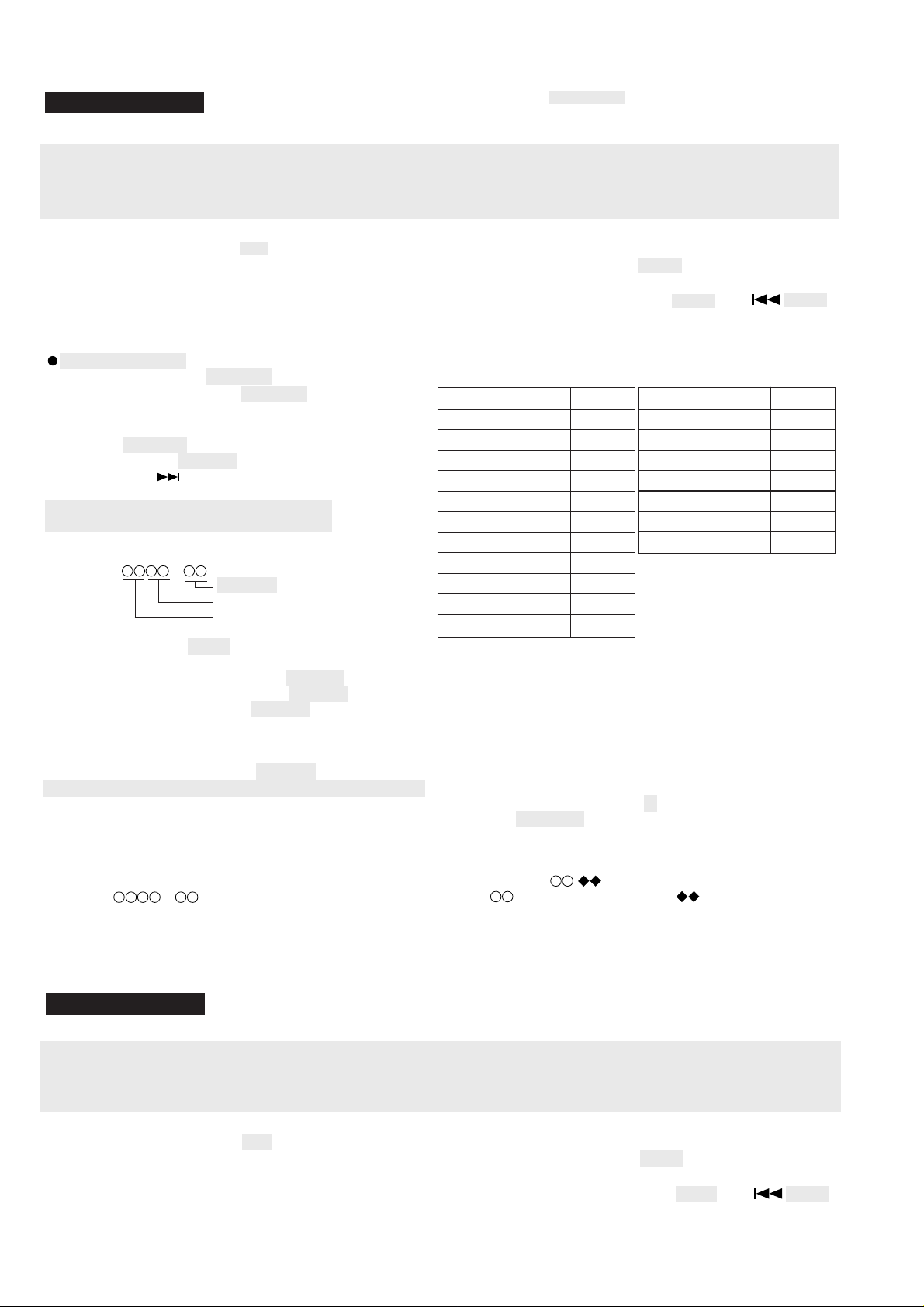
EEPROM (IC1402) writing procedure
1. Procedure to replace EEPROM and to write the initial
value of microcomputer in EEPROM
(See the MD-X5/MD-X5W service manual, page 28.)
(See the MD-X5H service manual, page 32.)
(1) Replace EEPROM.
(2) Refer to the latest EEPROM data list.
(3) Hold down the button and MD PLAY button, and press the
POWER button to enter the test mode.
When an MD is loaded, "AUT YOBI" will appear.
Press the MD PLAY button.
(4) Indication of version.
[ t s m
(5) Press the CD PLAY button 7 times.
[ E E P R O M S E T ]
(6) Perform the operation shown in the "EEPROM setting mode
chart", compare the indication with the EEPROM data list, and
make a setting according to the EEPROM data list, using VOL
UP botton or VOL DOWN button.
(7) Set the temperature reference value.
(Refer to "Temperature reference setting procedure".)
(8) The setting must conform to the EEPROM data list.
(9) Press the PRE-EQ button to write the data into the EEPROM.
e ]
EEPROM version (c to z)
Microcomputer ROM version
Model code
2. Temperature reference value setting procedure
(to be executed at room temperature within 21 to 29°C)
(1) Test mode stop state.
[ t s m
(2) Crrect temperature depending on ambient temperature according
to the following table.
e ]
For MD-X5
Ambient temperature
- 0.9 °C ~ + 2.7 °C -0 6 H
+ 2.7 °C ~ + 6.3 °C -0 5 H
+ 6.3 °C ~ + 10.0 °C -0 4 H
+ 10.0 °C ~ + 14.5 °C -0 3 H
+ 14.5 °C ~ + 18.2 °C -0 2 H
+ 18.2 °C ~ + 22.3 °C -0 1 H
+ 22.3 °C ~ + 26.3 °C ± 0 H
+ 26.3 °C ~ + 30.3 °C +0 1 H
+ 30.3 °C ~ + 34.6 °C +0 2 H
+ 34.6 °C ~ + 39.0 °C +0 3 H
+ 39.0 °C ~ + 42.8 °C +0 4 H
An example: When ambient temperature is 22°C and meadured
(3) Press the CD PLAY button 7 times.
[ E E P R O M S E T ]
(4) Press the MD PLAY button 1 times.(For MD-X5)
[ F o c u s ]
(5) Press the CD PLAY button 4 times.
[ T e m p ]
(6) Press once the MD PLAY button.
[ T E M P
: Measured temperature, : Temperature setting
(7) Set temperature to the value determined above, using the
VOL UP or VOL DOWN button.
(8) Press the MD STOP button.
[ T e m p ]
correction
temperature is 73H
Temperature setting = 73 H - 01 H
* When the measured temperature fluctuates between
two values, take lower one (if temperature fluctuates
between 73H and 72H, take 72H).
]
For MD-X5H/MD-X5W
Ambient temperature correction
+ 12.2 °C ~ + 15.8 °C -0 3 H
+ 15.9 °C ~ + 19.6 °C -0 2 H
+ 19.7 °C ~ + 23.2 °C -0 1 H
+ 23.2 °C ~ + 26.8 °C ± 0 H
+ 26.9 °C ~ + 30.7 °C +0 1 H
+ 30.8 °C ~ + 34.3 °C +0 2 H
+ 34.4 °C ~ + 37.9 °C +0 3 H
= 72 H
MD-X8/X8H/X8W
MD SECTION (See the MD-X8/MD-X8H/MD-X8W service manual, page 17.)
When the combination consisting of the pickup mechanism and the PWB is changed, enter the TEST mode, make a preliminary
automatic adjustment and then a full automatic adjustment. Then store the adjustment data in the EEPROM.
When the EEPROM is replaced, enter the TEST mode and write the data settings into the EEPROM. Then, make a preliminary
automatic adjustment and a full automatic adjustment. Finally, store the adjustment data in the EEPROM.
• Note
Remove the MD unit for repeir, and after installing it in the set, be dure to reset it and ascertain that reset has been done.
Resetting procedure (1) Unplug the AC cord from the socket, and hold down the RESET button provided at the rear side
for more than 10 seconds.
(2) Once set the TEST MODE (holding down the TEST MODE (X-BASS button) and button
together, press the POWER button), and then turn off power.
– 2 –
Page 3

MD-X5/X5H/X5W/X7/X7H/X8/X8H/X8W/XV300H/XV300X
2. Test mode
: Places to add/change/correct
Test mode setting method
1. Holding down the ENTER button and MD (PLAY/PAUSE) button, press the POWER button.
(State A is changed to state B .)
2. Insert the playback disc 1 (high reflection disc) or recording disc 2 (low reflection disc). (State C is set.)
Thus, the test mode state is set.
A tsm e : TEST MODE represents version of MD microcomputer.
TEST STOP state (When the MD (STOP) button is ressed in the C state, the indication A
is restored. To restore C again, press the CD (PLAY/ PAUSE)
button.)
B EJECT
TEST
C AUT YOBI
TEST
Entering the specific mode
Whenever the CD (PLAY/PAUSE) button is pressed, the mode is changed.
AUTO pre-adjustment AUTO adjustment RESULT Pre-adjustment RESULT MANUAL pre-adjustment
EEPROM setting MANUAL adjustment MANUAL pre-adjustment (MD-X8W Only)
• Canceling the test mode
When the ENTER button is pressed and held, and then the POWER button is pressed, the TEST mode will be canceled and the
power will be turned off.
(If the ENTER button is pressed, the unit will enter the MD stand-by mode.)
EEPROM (IC1402) writing procedure
1. Procedure to replace EEPROM and to write the initial
value of microcomputer in EEPROM
(See the MD-X8/MD-X8H/MD-X8W service manual, page
28.)
(1) Replace EEPROM.
(2) Refer to the latest EEPROM data list.
(3) Hold down the ENTER button and MD PLAY button, and press
the POWER button to enter the test mode.
When an MD is loaded, "AUT YOBI" will appear.
Press the MD STOP button. When the MD STOP button is pressed,
the version described in step (4) below will be displayed.
(4) Indication of version.
[ t s m
(5) Press the CD PLAY button 7 times.
[ E E P R O M S E T ]
(6) Perform the operation shown in the "EEPROM setting mode
chart", compare the indication with the EEPROM data list, and
make a setting according to the EEPROM data list, using
MULTI UP button or MULTI DOWN button.
(7) Set the temperature reference value.
(Refer to "Temperature reference setting procedure".)
(8) The setting must conform to the EEPROM data list.
(9) Press the ENTER button to write the data into the EEPROM.
e ]
EEPROM version (c to z)
Microcomputer ROM version
Model code
2. Temperature reference value setting procedure
(to be executed at room temperature within 21 to 29°C)
(1) Test mode stop state.
[ t s m
(2) Crrect temperature depending on ambient temperature according
to the following table.
Ambient temperature
+ 12.2 °C ~ + 15.8 °C -0 3 H
+ 15.9 °C ~ + 19.6 °C -0 2 H
+ 19.7 °C ~ + 23.2 °C -0 1 H
+ 23.2 °C ~ + 26.8 °C ± 0 H
+ 26.9 °C ~ + 30.7 °C +0 1 H
+ 30.8 °C ~ + 34.3 °C +0 2 H
+ 34.4 °C ~ + 37.9 °C +0 3 H
An example: When ambient temperature is 22°C and meadured
3) Press the CD PLAY button 7 times.
[ E E P R O M S E T ]
(4) Press the MD PLAY button 1 times.
[ F o c u s ]
(5) Press the CD PLAY button 4 times.
[ T e m p ]
(6) Press once the MD PLAY button.
[ T E M P
: Measured temperature, : Temperature setting
(7) Set temperature to the value determined above, using the
MULTI UP or MULTI DOWN button.
(8) Press the MD STOP button.
[ T e m p ]
e ]
correction
temperature is 73H
Temperature setting = 73 H - 01 H
= 72 H
* When the measured temperature fluctuates between
two values, take lower one (if temperature fluctuates
between 73H and 72H, take 72H).
]
– 3 –
Page 4

MD-X5/X5H/X5W/X7/X7H/X8/X8H/X8W/XV300H/XV300X
EEPROM Data List (As of November, 1998)
Version
Item indication
SLCTt 40 H 40 H 40 H
SLCTm 53 H 53 H 53 H
TCRSCIP 16 H 16 H 16 H
COTLVP 14 H 14 H 14 H
COTLVr 28 H 28 H 28 H
WAITm FF H FF H FF H
SLG 35 H 35 H 35 H35 H
SL2 27 H 27 H 27 H
SLDLIM 65 H 65 H 65 H
SLDLEV 16 H 16 H 16 H
SLKLVk 55 H 55 H 55 H
SLKLVt 3A H 3A H 3A H
SLKLVm 55 H 55 H 55 H
CONTRL1 80 H 80 H 80 H
CONTRL2 02 H 03 H 04 H
SPKLEVm 26 H 26 H 26 H
ADJTTM 14 H 14 H 14 H
HDEQAD 90 H 90 H 90 H
LDEQAD 8F H 8F H 8F H
GDEQAD 91 H 91 H 91 H
MDEQBC 90 H 90 H 90 H
LDEQBC 8F H 8F H 8F H
GDEQBC 8A H 8A H 8A H
HALSG 21 H 21 H 21 H
LALSG 21 H 21 H 21 H
CALSG 21 H 21 H 21 H
HALSOFS FE H FE H FE H
LALSOFS 00 H 00 H 00 H
GALSOFS 00 H 00 H 00 H
02
Setting
03
Setting04Setting
: Places to add/change/correct
Version
Item indication
FG 97 H D0 H D0 H
FF1 9E H 9E H 9E H
FF2 E0 H E0 H E0 H
FZHLEV ED H ED H ED H
FOKLEVn 08 H 08 H 08 H
FOKLEVf 08 H 08 H 08 H
FOKLPFn 00 H 00 H 00 H
FOKLPFf 88 H 88 H 88 H
WAITf 90 H 90 H 90 H
SPG 20 H 20 H 20 H
SPG-in B8 H B8 H B8 H
SPG-mid 76 H 76 H 80 H
SPG-out 50 H 50 H 60 H
SP1 10 H 10 H 10 H
SP2 87 H 87 H 87 H
SP3 E3 H E3 H E3 H
SP4 E3 H E3 H E3 H
SP5 10 H 10 H 10 H
SPDLIM 78 H 78 H 78 H
TG 45 H 5F H 5F H
TF1 70 H 70 H 70 H
TF2 E0 H E0 H E0 H
SVCNT4 01 H 01 H 01 H
TRBLVo 53 H 53 H 53 H
TRBLVt 60 H 60 H 60 H
TRKLVo 4C H 4C H 4C H
TRKLVt 38 H 38 H 38 H
TDPWo 89 H 89 H 89 H
TDPWt 1A H 1A H 1A H
SLCTo 00 H 00 H 00 H
02
Setting
03
Setting04Setting
Used IC
(MD microcomputer)
Before
RH-IX0232AWZZ
After
RH-IX0232AWZZ
Used IC
(MD microcomputer)
– 4 –
Before
RH-IX0232AWZZ
After
RH-IX0232AWZZ
Page 5

MD-X5/X5H/X5W/X7/X7H/X8/X8H/X8W/XV300H/XV300X
MD-XV300H/XV300X
: Places to add/change/correct
EEPROM (IC1402) writing procedure
1. Procedure to replace EEPROM and to write the initial value of microcomputer in EEPROM
(See the MD-XV300H service manual, page 27.) (See the MD-XV300X service manual, page 25.)
(1) Replace EEPROM.
(2) Refer to the latest EEPROM data list.
(3) Hold down the ENTER button and MD PLAY button, plug the AC cord into the AC socket, and start up the test mode.
(Reference) After a disc has been inserted while EJECT TEST is being displayed, the unit will enter the AUTO TEST mode.
Then, when the MD STOP button is pressed, the version described in step (4) will appear.
(4) Indication of version.
[ t s m e ]
EEPROM version (c to z)
Microcomputer ROM version
Model code
(5) Press the CD PLAY button 4 times.
[ E E P R O M S E T ]
(6) Perform the operation shown in the "EEPROM setting mode chart", compare the indication with the EEPROM data list,
and make a setting according to the EEPROM data list, using JOG dial UP button or JOG dial DOWN button.
(7) Set the temperature reference value. (Refer to "Temperature reference setting procedure".)
(8) The setting must conform to the EEPROM data list.
(9) Press the ENTER button to write the data into the EEPROM.
2. Temperature reference value setting procedure
(to be executed at room temperature within 21 to 29°C)
(1) TEST mode stop state.
[ t s m e ]
(2) Crrect temperature depending on ambient temperature according to the following table.
Ambient
temperature (°C)
21 ~ 22.3 - 0 1 H
22.3 < 26.3 ± 0
26.3 < 29 + 0 1 H
An example: When ambient temperature is 22°C and meadured temperature is 73H
Temperature setting = 73 H - 01 H
= 72 H
* When the measured temperature fluctuates between two values, take lower one (if temperature
fluctuates between 73H and 72H, take 72H).
(While EEPROM SET is being displayed)
(3) Press the MD PLAY button.
[ F o c u s ]
(4) Press the CD PLAY button 4 times.
[ T e m p ]
(5) Press the MD PLAY button.
[ T E M P ] : Measured temperature, : Temperature setting
(6) Set temperature to the value determined above, using the JOG dial UP or JOG dial DOWN button.
(7) Press the MD PLAY button.
[ T e m p ]
(Then, press the MD STOP button to enter the EEPROM SET mode.)
Temperature
correction
– 5 –
Page 6

MD-X5/X5H/X5W/X7/X7H/X8/X8H/X8W/XV300H/XV300X
EEPROM Data List (As of November, 1998)
Data Name
FG 98 98 98 67 67
FF1 70 70 70 70 70
FF2 F0 F0 F0 F0 F0
FF3 FE FE FE FE FE
FF4 00 00 00 00 00
FZHLEV 13 13 13 13 ED
FOKLEVn F6 F6 F6 F6 F6
FOKLEVf 7F 7F 7F 7F 7F
FOKLPFn 00 00 00 00 00
FOKLPFf 88 88 88 88 88
WAITf 3A 3A 3A 3A 3A
SPG 18 18 18 18 18
SPG-in 88 88 88 88 88
SPG-mid 66 66 66 66 66
SPG-out 47 47 47 47 47
SP1 10 10 10 10 10
SP2 87 87 87 87 87
SP3 E9 E9 E9 E9 E9
SP4 EA EA EA EA EA
SP5 10 10 10 10 10
TEMP 73 73 73 73 73
CONTRL1 80 80 80 80 80
CONTRL2 01 02 03 04 05
DFLT 02 03 04 05
Version
: Places to add/change/correct
Data Name
TG 40 48 45 45 45
TF1 70 70 95 95 95
TF2 F0 F0 E0 E0 E0
TRBLVo 40 40 40 40 40
TRBLVt 60 60 60 60 60
TRKLVo 48 48 48 48 48
TRKLVt 28 28 28 28 28
TDPWo 75 75 75 75 75
TDPWt 1A 1A 1A 1A 1A
SLCTo 00 00 00 00 00
SLCTt 40 40 40 40 40
SLCTm 53 53 53 53 53
COTLVHp 14 14 14 14 14
COTLVLp EC EC EC EC EC
COTLVHr 28 28 28 28 28
COTLVLr D8 D8 D8 D8 D8
WAITm 9 0 90 90 90 90
SLG 35 35 35 35 35
SL2 27 27 27 27 27
SLDLEV 0A 0A 0A 0A 0A
SLKLEVk 78 78 78 78 78
SLKLEVt 50 50 50 50 50
SLKLEVm 78 78 78 78 78
DFLT 02 03 04 05
Version
Before RH-IX2578AFZZ After RH-IX2578AFZZ
Before RH-IX2578AFZZ After RH-IX2578AFZZ
– 6 –
 Loading...