

Page 1
TopPage
SUPPLEMENT ATTACHED
LC-C4662U/LC-C5262U
SERVICE MANUAL
No. S47E4LCC5262U
LCD COLOR TELEVISION
LC-C4662U
MODELS
In the interests of user-safety (Required by safety regulations in some countries) the set should
be restored to its original condition and only parts identical to those specified should be used.
LC-C5262U
OUTLINE
This model is based on the LC-46D62U/LC-52D62U and partially modified.
For the contents not covered in this Service Manual, accordingly, please refer to the LC-46D62U/LC-52D62U
(No. S86V8LC52D62U) Service Manual.
CONTENTS
DIFFERENCES FROM BASE MODEL
LIST OF CHANGED PARTS (LC-C4662U)
LIST OF CHANGED PARTS (LC-C5262U)
SAFETY PRECAUTION
IMPORTANT SERVICE SAFETY PRE-
CAUTION ...........................................................ii
PRECAUTIONS A PRENDRE LORS DE
LA REPARATION.............................................. iii
PRECAUTIONS FOR USING LEAD-FREE
SOLDER ........................................................... iv
...................i
...................i
CHAPTER 1. SPECIFICATIONS
[1] SPECIFICATIONS ......................................... 1-1
CHAPTER 2. OPERATION MANUAL
[1] OPERATION MANUAL .................................. 2-1
CHAPTER 3. DIMENSIONS
[1] DIMENSIONS ................................................ 3-1
Parts Guide
Parts marked with " " are important for maintaining the safety of the set. Be sure to replace these parts with specified ones for maintaining the
safety and performance of the set.
This document has been published to be used for
after sales service only.
The contents are subject to change without notice.
Page 2
LC-C4662U/LC-C5262U
i
LC-C4662U/LC-C5262U
Service Manual
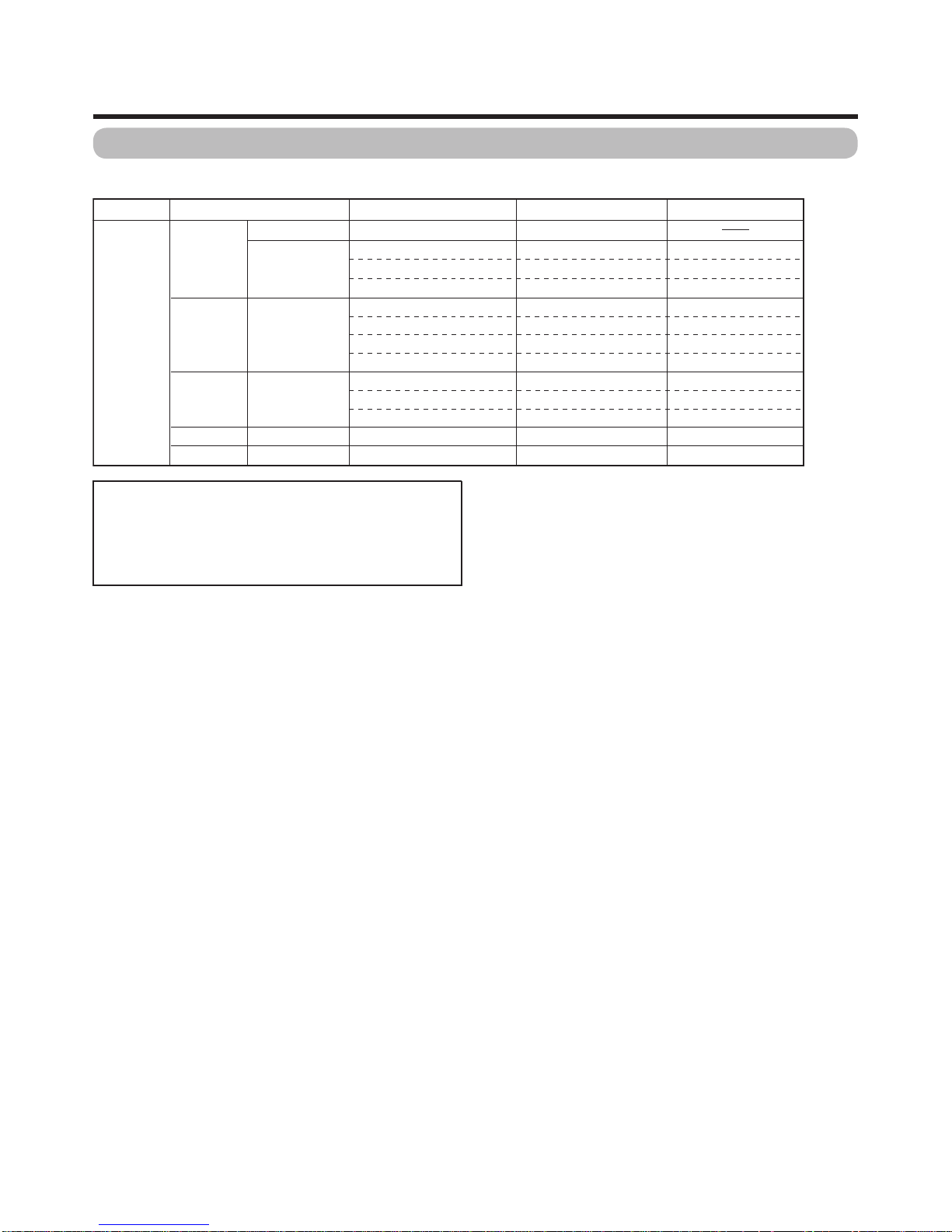
DIFFERENCES FROM BASE MODEL
LIST OF CHANGED PARTS (LC-C4662U)
LIST OF CHANGED PARTS (LC-C5262U)
Ref. No. Description LC-46D62U LC-C4662U Note
PRINTED WIRING BOARD ASSEMBLIES
R/C, LED Unit DUNTKD909FM02 ← No Change
KEY Unit DUNTKD910FM02 ← No Change
MAIN Unit DUNTKD934FM01 ← No Change
TERMINAL Unit DUNTKD935FM01 ← No Change
POWER SUPPLY Unit RDENCA184WJQZ ← No Change
LCD PANEL
LCD PANEL Unit R1LK460D3LZ10Y ← No Change
Refer to the PARTS GUIDE for CABINET PARTS, SUPPLIED ACCESSORIES, PACKING PARTS and SERVICE JIGS.
Ref. No. Description LC-52D62U LC-C5262U Note
PRINTED WIRING BOARD ASSEMBLIES
R/C, LED Unit DUNTKD909FM02 ← No Change
KEY Unit DUNTKD910FM02 ← No Change
MAIN Unit DUNTKD934FM02 ← No Change
TERMINAL Unit DUNTKD935FM02 ← No Change
POWER SUPPLY Unit RDENCA184WJQZ ← No Change
LCD PANEL
LCD PANEL Unit R1LK520D3LZ10Y ← No Change
Refer to the PARTS GUIDE for CABINET PARTS, SUPPLIED ACCESSORIES, PACKING PARTS and SERVICE JIGS.
Page 3
LC-C4662U/LC-C5262U
ii
LC-C4662U/LC-C5262U
Service Manual
SAFETY PRECAUTION
IMPORTANT SERVICE SAFETY PRECAUTION
WARNING
1. For continued safety, no modification of any circuit should be
attempted.
2. Disconnect AC power before servicing.
BEFORE RETURNING THE RECEIVER (Fire &
Shock Hazard)
Before returning the receiver to the user, perform the following
safety checks:
3. Inspect all lead dress to make certain that leads are not pinched,
and check that hardware is not lodged between the chassis and
other metal parts in the receiver.
4. Inspect all protective devices such as non-metallic control knobs,
insulation materials, cabinet backs, adjustment and compartment
covers or shields, isolation resistor-capacitor networks, mechanical
insulators, etc.
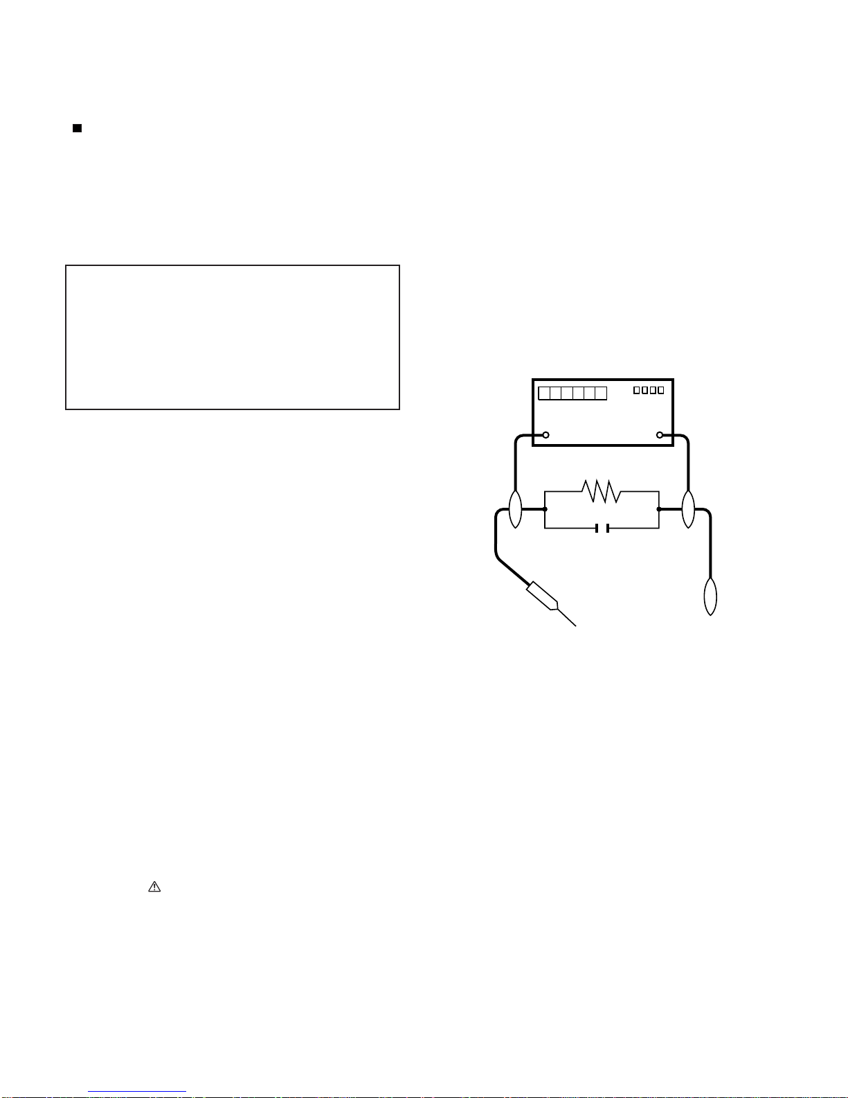
5. To be sure that no shock hazard exists, check for leakage current in
the following manner.
• Plug the AC cord directly into a 120 volt AC outlet.
• Using two clip leads, connect a 1.5k ohm, 10 watt resistor paralleled by a 0.15µF capacitor in series with all exposed metal cabinet
parts and a known earth ground, such as electrical conduit or electrical ground connected to an earth ground.
• Use an AC voltmeter having with 5000 ohm per volt, or higher, sensitivity or measure the AC voltage drop across the resistor.
• Connect the resistor connection to all exposed metal parts having a
return to the chassis (antenna, metal cabinet, screw heads, knobs
and control shafts, escutcheon, etc.) and measure the AC voltage
drop across the resistor.
All checks must be repeated with the AC cord plug connection
reversed. (If necessary, a nonpolarized adaptor plug must be used
only for the purpose of completing these checks.)
Any reading of 0.75 Vrms (this corresponds to 0.5 mA rms AC.) or
more is excessive and indicates a potential shock hazard which
must be corrected before returning the monitor to the owner.
///////////////////////////////////////////////////////////////////////////////////////////////////////////////////////////////////////////////////////////////////////////////////////////////////////////////////////////////////////////
SAFETY NOTICE
Many electrical and mechanical parts in LCD color television have
special safety-related characteristics.
These characteristics are often not evident from visual inspection, nor
can protection afforded by them be necessarily increased by using
replacement components rated for higher voltage, wattage, etc.
Replacement parts which have these special safety characteristics are
identified in this manual; electrical components having such features
are identified by " " and shaded areas in the Replacement Parts List
and Schematic Diagrams.
For continued protection, replacement parts must be identical to those
used in the original circuit.
The use of a substitute replacement parts which do not have the same
safety characteristics as the factory recommended replacement parts
shown in this service manual, may create shock, fire or other hazards.
///////////////////////////////////////////////////////////////////////////////////////////////////////////////////////////////////////////////////////////////////////////////////////////////////////////////////////////////////////////
Service work should be performed only by qualified service technicians who are thoroughly familiar with all safety checks and the
servicing guidelines which follow:
CAUTION: FO R C O N T I N U E D PROTECTION
AGAINST A RISK OF FIRE REPLACE ONLY WITH
SAME TYPE FUSE.
F701 (250V, 8A), F702 (250V, 1A)
F4702 (250V, 4A)
F4701/F4703 (250V, 3A, 127
O
C)
DVM
AC SCALE
1.5k ohm
10W
TO EXPOSED
METAL PARTS
CONNECT TO
KNOWN EARTH
GROUND
0.15µF
TEST PROBE
Page 4
LC-C4662U/LC-C5262U
iii
PRECAUTIONS A PRENDRE LORS DE LA REPARATION
De nombreuses pièces, électriques et mécaniques, dans les téléviseur ACL présentent des caractéristiques spéciales relatives à la sécurité, qui ne sont souvent pas évidentes à vue. Le degré de protection ne peut pas être nécessairement augmentée en utilisant des
pièces de remplacement étalonnées pour haute tension, puissance,
etc.
Les pièces de remplacement qui présentent ces caractéristiques sont
identifiées dans ce manuel; les pièces électriques qui présentent ces
particularités sont identifiées par la marque " " et hachurées dans la
liste des pièces de remplacement et les diagrammes schématiques.
Pour assurer la protection, ces pièces doivent être identiques à celles
utilisées dans le circuit d'origine. L'utilisation de pièces qui n'ont pas
les mêmes caractéristiques que les pièces recommandées par l'usine,
indiquées dans ce manuel, peut provoquer des électrocutions, incendies, radiations X ou autres accidents.
AVERTISSEMENT
1.
2.
3.
4.
5.
•
•
•
•
/////////////////////////////////////////////////////////////////////////////////////////////////////////////////////////////////////////////////////////////////////////////////////////////////////////////////////////////////////////////
/////////////////////////////////////////////////////////////////////////////////////////////////////////////////////////////////////////////////////////////////////////////////////////////////////////////////////////////////////////////
Ne peut effectuer la réparation qu' un technicien spécialisé qui s'est parfaitement accoutumé à toute vérification de sécurité et aux
conseils suivants.
N'entreprendre aucune modification de tout circuit. C'est dangereux.
Débrancher le récepteur avant toute réparation.
Inspecter tous les faisceaux de câbles pour s'assurer que les fils
ne soient pas pincés ou qu'un outil ne soit pas placé entre le châssis et les autres pièces métalliques du récepteur.
Inspecter tous les dispositifs de protection comme les boutons de
commande non-métalliques, les isolants, le dos du coffret, les couvercles ou blindages de réglage et de compartiment, les réseaux
de résistancecapacité, les isolateurs mécaniques, etc.
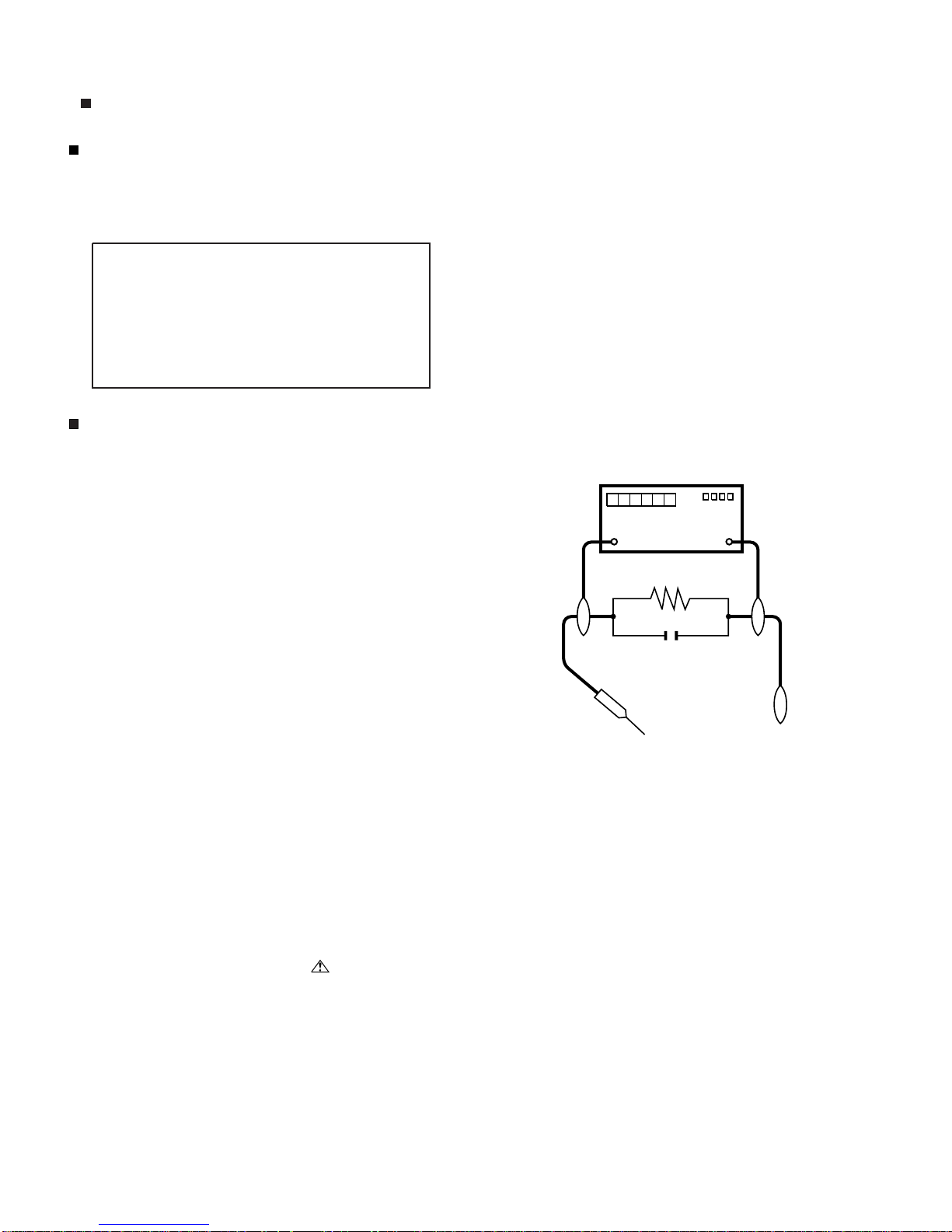
S'assurer qu'il n'y ait pas de danger d'électrocution en vérifiant la
fuite de courant, de la facon suivante:
Brancher le cordon d'alimentation directem-ent à une prise de courant de 120V. (Ne pas utiliser de transformateur d'isolation pour
cet essai).
A l'aide de deux fils à pinces, brancher une résistance de 1.5 kΩ
10 watts en parallèle avec un condensateur de 0.15µF en série
avec toutes les pièces métalliques exposées du coffret et une terre
connue comme une conduite électrique ou une prise de terre
branchée à la terre.
Utiliser un voltmètre CA d'une sensibilité d'au moins 5000Ω/V pour
mesurer la chute de tension en travers de la résistance.
Toucher avec la sonde d'essai les pièces métalliques exposées qui
présentent une voie de retour au châssis (antenne, coffret métallique, tête des vis, arbres de commande et des boutons, écusson,
etc.) et mesurer la chute de tension CA en-travers de la résistance.
Toutes les vérifications doivent être refaites après avoir inversé la
fiche du cordon d'alimentation. (Si nécessaire, une prise
d'adpatation non polarisée peut être utilisée dans le but de terminer ces vérifications.)
La tension de pointe mesurèe ne doit pas dépasser 0.75V (correspondante au courant CA de pointe de 0.5mA).
Dans le cas contraire, il y a une possibilité de choc électrique qui
doit être supprimée avant de rendre le récepteur au client.
PRECAUTION:POURLAPROTECTIONCONTINUE CONTRE LES RISQUES D'INCENDIE,
REMPLACER LE FUSIBLE
VERIFICATIONS CONTRE L'INCEN-DIE ET LE
CHOC ELECTRIQUE
Avant de rendre le récepteur à l'utilisateur, effectuer les vérifications suivantes.
DVM
ECHELLE CA
1.5k ohm
10W
0.15
µ
F
SONDE D'ESSAI
AUX PIECES
METALLIQUES
EXPOSEES
BRANCHER A UNE
TERRE CONNUE
AVIS POUR LA SECURITE
F701 (250V, 8A), F702 (250V, 1A)
F4702 (250V, 4A)
F4701/F4703 (250V, 3A, 127
O
C)
Page 5

LC-C4662U/LC-C5262U
iv
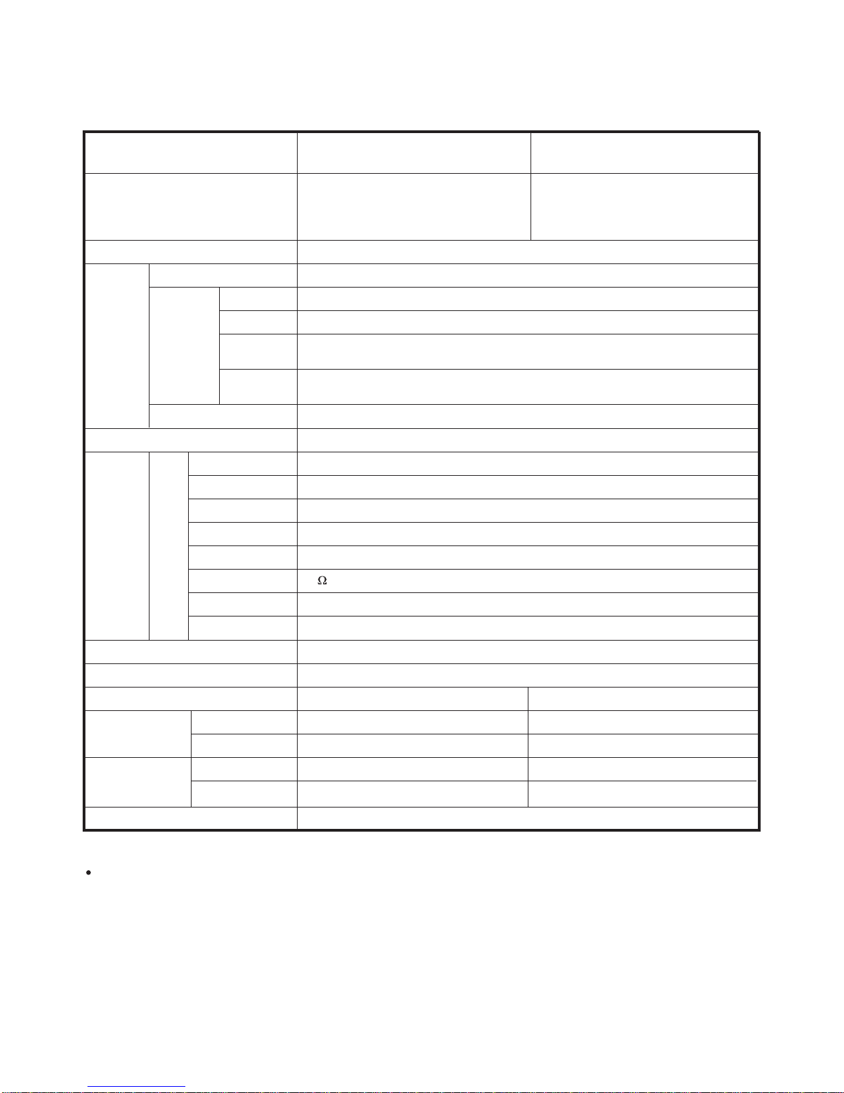
PRECAUTIONS FOR USING LEAD-FREE SOLDER
Employing lead-free solder
• “PWBs” of this model employs lead-free solder. The LF symbol indicates lead-free solder, and is attached on the PWBs and service manuals. The
alphabetical character following LF shows the type of lead-free solder.
Example:
Using lead-free wire solder
• When fixing the PWB soldered with the lead-free solder, apply lead-free wire solder. Repairing with conventional lead wire solder may cause damage or accident due to cracks.
As the melting point of lead-free solder (Sn-Ag-Cu) is higher than the lead wire solder by 40 °C, we recommend you to use a dedicated soldering
bit, if you are not familiar with how to obtain lead-free wire solder or soldering bit, contact our service station or service branch in your area.
Soldering
• As the melting point of lead-free solder (Sn-Ag-Cu) is about 220 °C which is higher than the conventional lead solder by 40 °C, and as it has poor
solder wettability, you may be apt to keep the soldering bit in contact with the PWB for extended period of time. However, Since the land may be
peeled off or the maximum heat-resistance temperature of parts may be exceeded, remove the bit from the PWB as soon as you confirm the
steady soldering condition.
Lead-free solder contains more tin, and the end of the soldering bit may be easily corroded. Make sure to turn on and off the power of the bit as
required.
If a different type of solder stays on the tip of the soldering bit, it is alloyed with lead-free solder. Clean the bit after every use of it.
When the tip of the soldering bit is blackened during use, file it with steel wool or fine sandpaper.
• Be careful when replacing parts with polarity indication on the PWB silk.
Lead-free wire solder for servicing
Indicates lead-free solder of tin, silver and copper. Indicates lead-free solder of tin, silver and copper.
PARTS CODE
PRICE
RANK
PART
DELIVERY
DESCRIPTION
ZHNDAi123250E BL J φ0.3mm 250g (1roll)
ZHNDAi126500E BK J φ0.6mm 500g (1roll)
ZHNDAi12801KE BM J φ1.0mm 1kg (1roll)
Page 6
LC-C4662U/LC-C5262U
1 – 1
LC-C4662U/LC-C5262U
Service Manual
CHAPTER 1. SPECIFICATIONS
[1] SPECIFICATIONS
Digital cable
*
1
(64/256 QAM)
1-135ch (non-scrambled channel only)
*
1
Emergency alert messages via Cable are unreceivable.
*
2
The dimensional drawings are shown on the inside back cover.
As part of policy of continuous improvement, SHARP reserves the right to make design and specification changes for product
improvement without prior notice. The performance specification figures indicated are nominal values of production units.
There may be some deviations from these values in individual units.
LCD panel
Number of dots
TV
Function
TV-standard (CCIR)
Receiving
Channel
VHF/UHF
CATV
Digital Terrestrial
Broadcast (8VSB)
Audio multiplex
Audio out
Terminals
Rear
INPUT 1
INPUT 2
INPUT 3
INPUT 4
INPUT 5
ANTENNA
DIGITAL AUDIO OUTPUT
OUTPUT
OSD language
Power Requirement
Power Consumption
Weight
Dimension*
2
(W H D)
Operating temperature
6,220,800 dots (1920 1080 3 dots)
American TV Standard ATSC/NTSC System
VHF 2-13ch, UHF 14-69ch
1-135ch (non-scrambled channel only)
2-69ch
BTSC System
15W 2
AV in, COMPONENT in
AV in, COMPONENT in
S-VIDEO in, AV in
Audio in, HDMI in with HDCP
HDMI in with HDCP
75 Unbalance, F Type 1 for Analog (VHF/UHF/CATV) and Digital (AIR/CABLE)
Optical Digital audio output 1 (PCM/Dolby Digital)
Audio out
English/French/Spanish
AC 120 V, 60 Hz
32°F to 104°F (0°C to 40°C)
Item
Model: LC-C4662U Model: LC-C5262U
46" Advanced Super View & BLACK TFT
LCD
(Actual screen size 45 63/64"measured
diagonally)
52"
Advanced Super View & BLACK TFT
LCD
(Actual screen size 52 1/32" measured
diagonally)
TV only
TV stand
TV stand
TV only
270 W (0.7 W Standby with AC 120V) 302 W (0.7 W Standby with AC 120V)
78.3 lbs./35.5 kg
68.3 lbs./31.0 kg
44
3
/82843/
64
457/64inch
89.3 lbs./40.5 kg
79.4 lbs./36.0 kg
49
47
/64347/
32
1211/64inch
49
47
/643125/
32
459/64inch
44
3
/8317/641211/64inch
Page 7
LC-C4662U/LC-C5262U
2 – 1
LC-C4662U/LC-C5262U
Service Manual
CHAPTER 2. OPERATION MANUAL
[1] OPERATION MANUAL
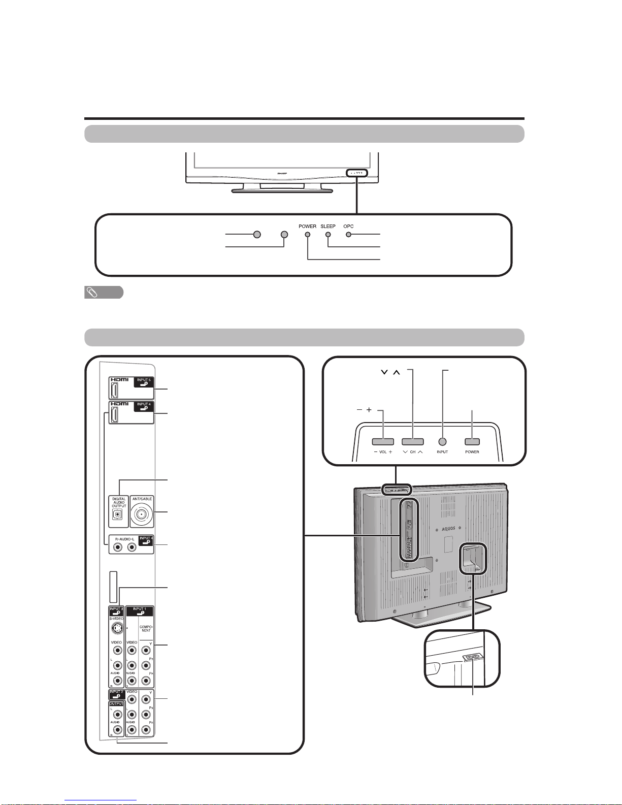
Part names
POWER button
TV (Front)
Channel buttons
(CH /)
Volume
buttons
(VOL /)
INPUT button
OPC indicator
POWER indicator
OPC sensor*
Remote control sensor
NOTE
*OPC: Optical Picture Control
SLEEP indicator
TV (Rear/Top)
HDMI terminal (INPUT 4)
INPUT 3 terminals
AUDIO OUTPUT terminals
HDMI terminal (INPUT 5)
DIGITAL AUDIO OUTPUT terminal
Antenna/Cable in
INPUT 1 terminals
AC INPUT terminal
AUDIO terminals (INPUT 4)
INPUT 2 terminals
Page 8

LC-C4662U/LC-C5262U
2 – 2
3
2
114
5
6
4
8
17
15
16
18
19
7
20
10
9
21
11 23
24
25
12
13 27
22
26
Part names
1 TV POWER: Switch the TV power on or enters standby.
2 DISPLAY: Display the channel information.
3 SOURCE POWER: Turns the power of the external
equipment on and off.
4 External equipment operational buttons: Operate the
external equipment.
50_9: Set the channel.
6 (DOT):
7INPUT:Select a TV input source. (TV, INPUT 1, INPUT 2,
INPUT 3, INPUT 4, INPUT 5)
8VOL/:Set the volume.
9 SURROUND: Select Surround settings.
10 FREEZE: Set the still image. Press again to return to
normal screen.
11 EXIT: Turn off the menu screen.
12 SLEEP:Set the sleep timer.
13 AUDIO: Selects the MTS/SAP or the audio mode during
multi-channel audio broadcasts.
14 FUNCTION: Switches the remote control for TV, CBL/
SAT, VCR, DVD and AUDIO operation. Indicator lights up
for the current mode.
* To enter the code registration mode, you need to press
FUNCTION and DISPLAY at the same time.
15 LIGHT : When pressed all buttons on the remote
control unit will light. The lighting will turn off if no
operations are performed within about 5 seconds. This
button is used for performing operations in low-light
situations.
16 VIEW MODE: Select the screen size.
17 ENT: Jumps to a channel after selecting with the 0_9
buttons.
18 FLASHBACK:Return to the previous channel or external
input mode.
19
CH / : Select the channel.
20 MUTE: Mute the sound.
21 MENU: Display the menu screen.
22 ////ENTER: Select a desired item on the
screen.
23 RETURN: Return to the previous menu screen.
24 FAVORITE CH
A, B, C, D: Select 4 preset favorite channels in 4 different
categories.
While watching, you can toggle the selected channels by
pressing A, B, C and D.
25 FAVORITE:Set the favorite channels.
26 CC: Display captions from a closed-caption source.
27 AV MODE: Select an audio or video setting. (When the
input source is TV, INPUT 1, 2 or 3: STANDARD, MOVIE,
GAME, USER, DYNAMIC (Fixed), DYNAMIC. When
the input source is INPUT 4 or 5: STANDARD, MOVIE,
GAME, PC, USER, DYNAMIC (Fixed), DYNAMIC)
Remote control unit
NOTE
When using the remote control unit, point it at the TV.
Page 9
LC-C4662U/LC-C5262U
2 – 3
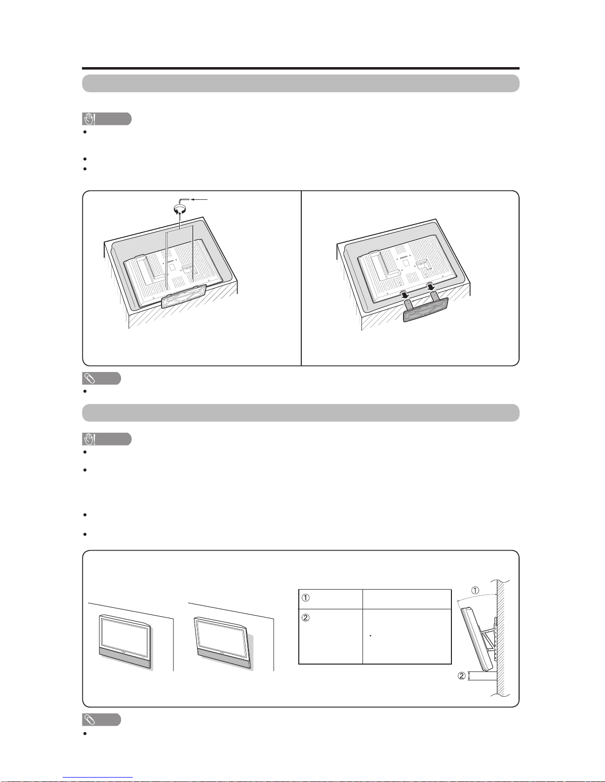
Removing the stand
Before detaching (or attaching) stand, unplug the AC cord from the AC INPUT terminal.
CAUTION
Do not remove the stand from the TV unless using an optional wall mount bracket to mount it.
Before attaching/detaching stand
Before performing work make sure to turn off the TV.
Before performing work spread cushioning over the base area to lay the TV on. This will prevent it from being
damaged.
Setting the TV on the wall
CAUTION
This TV should be mounted on the wall only with the AN-52AG1 (SHARP) wall mount bracket. The use of other
wall mount brackets may result in an unstable installation and may cause serious injuries.
Installing the TV requires special skill that should only be performed by qualified service personnel. Customers
should not attempt to do the work themselves. SHARP bears no responsibility for improper mounting or
mounting that results in accident or injury.
Using an optional bracket to mount the TV
You can ask a qualified service professional about using an optional AN-52AG1 bracket to mount the TV to the
wall.
Carefully read the instructions that come with the bracket before beginning work.
Hanging on the wall
AN-52AG1 wall mount bracket.
Vertical mounting
About setting the TV angle and height adjustment
Unfasten the four screws used to secure the stand in
place.
Detach the stand from the TV.
(Hold the stand so it will not drop from the edge of the
base area.)
Appendix
NOTE
To attach the stand, perform the above steps in reverse order.
Angular mounting
12
Hex key
NOTE
Detach the cable clamps on the rear of the TV when using the optional mount bracket.
1
63
/64( 5)/0/
1
63
/64(5)
can be moved 1
63
/
64
(5) up or down
Unit: inch (cm)
0/5/10/15/20°AngleofTV
Height
Adjustment
AA
Page 10
LC-C4662U/LC-C5262U
2 – 4
The TV sometimes makes a
cracking sound.
This is not a malfunction. This happens when the cabinet slightly expands and
contracts according to change in temperature. This does not affect the TV's
performance.
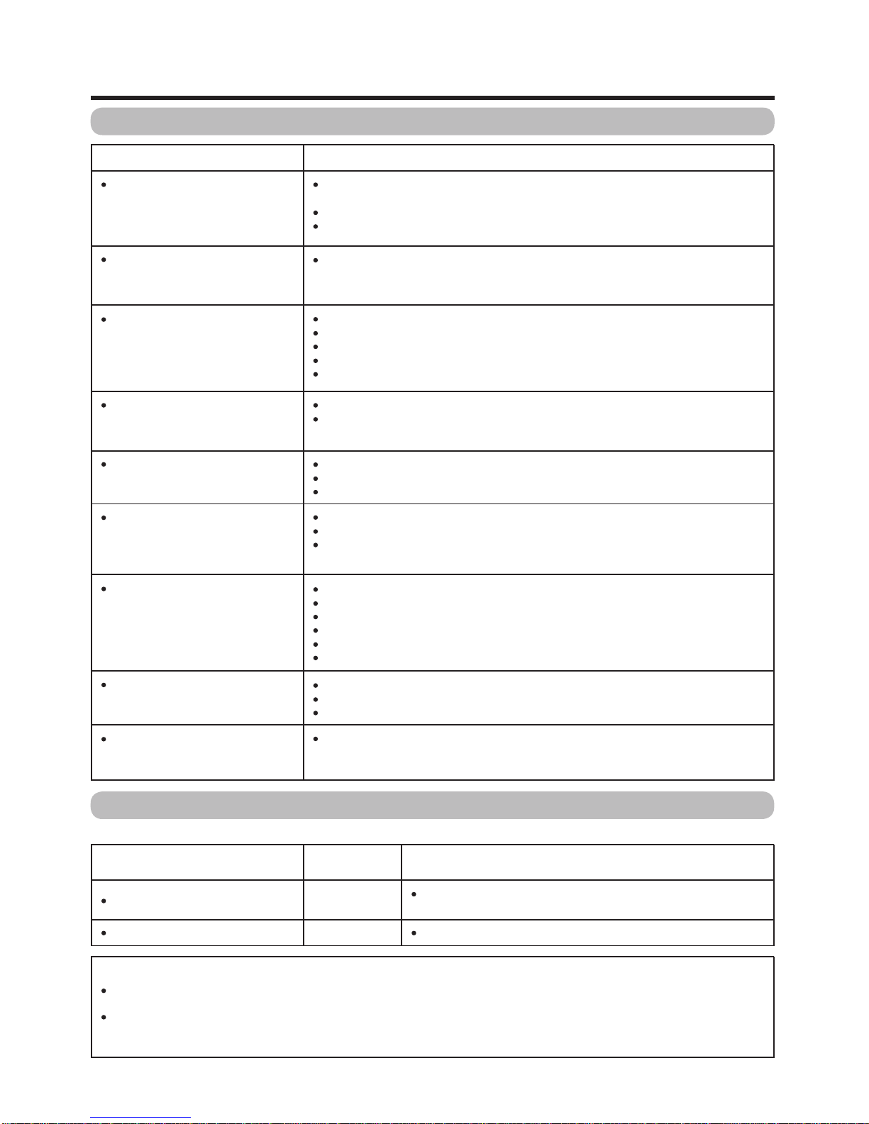
Troubleshooting
Possible Solution
Is the volume too low?
Is "Variable" selected in "Output Select"?
Have you pressed MUTE on the remote control unit?
Cautions regarding use in high and low temperature environments
Appendix
Problem
No power
Unit cannot be operated.
Remote control unit does not
operate.
Picture is cut off/with sidebar
screen.
Strange color, light color, or color
misalignment
Power is suddenly turned off.
No picture
No sound
Check if you pressed TV POWER on the remote control unit. If the
indicator on the TV does not light up, press POWER on the TV.
IstheACcorddisconnected?
Has the power been turned on?
External influences such as lightning, static electricity, may cause improper
operation. In this case, operate the unit after first turning on the power of the TV or
unplugging the AC cord and replugging it in after 1 or 2 minutes.
Is the FUNCTION set correctly? Set it to the TV setting position.
Are batteries inserted with polarity ( +,_) aligned?
Are batteries worn out? (Replace with new batteries.)
Are you using it under strong or fluorescent lighting?
Is a fluorescent light illuminated near the remote control sensor?
Is the image position correct?
Are screen mode adjustments such as picture size made correctly?
Adjust the picture tone.
Is the room too bright? The picture may look dark in a room that is too bright.
Check the input signal setting.
Is the sleep timer set?
Check the power control settings.
The unit's internal temperature has increased. Remove any objects blocking vent
or clean.
Is connection to other components correct?
Is correct input signal source selected after connection?
Is the correct input selected?
Is picture adjustment correct?
Is "On" selected in "Audio Only"?
Is a non-compatible signal being input?
When the unit is used in a low temperature space (e.g. room, office), the picture may leave trails or appear slightly delayed.
This is not a malfunction, and the unit will recover when the temperature returns to normal.
Do not leave the unit in a hot or cold location. Also, do not leave the unit in a location exposed to direct sunlight or near a
heater, as this may cause the cabinet to deform and the Liquid Crystal panel to malfunction.
Storage temperature: 4°F to 140°F ( 20°C to 60°C)
Troubleshooting-Digital broadcasting
The error message about reception of broadcast
Failed to receive broadcast.
E203 Check the broadcast time in the program guide.
The example of an error
message displayed on a screen
No broadcast now.
Error code
E202
Possible Solution
Check the antenna cable. Check that the antenna is correctly
setup.
++
__
Page 11
LC-C4662U/LC-C5262U
2 – 5
PC format compatibility chart
DDC is a registered trademark of Video Electronics
Standards Association.
Power Management is a registered trademark of Sun
Microsystems, Inc.
VGA and XGA are registered trademarks of International
Business Machines Co., Inc.
PC
31.5 kHz
31.5 kHz
37.9 kHz
37.5 kHz
35.1 kHz
37.9 kHz
48.1 kHz
46.9 kHz
48.4 kHz
56.5 kHz
60.0 kHz
47.7 kHz
64.0 kHz
640 x 480
720 x 400
VGA
800 x 600SVGA
XGA 1024 x 768
WXGA 1360 x 768
SXGA 1280 x 1024
70 Hz
60 Hz
72 Hz
75 Hz
56 Hz
60 Hz
72 Hz
75 Hz
60 Hz
70 Hz
75 Hz
60 Hz
60 Hz
O
O
O
O
O
O
O
O
O
O
O
O
PC Horizontal Frequency VESA StandardResolution Vertical Frequency
It is necessary to set the PC format correctly to display XGA and WXGA signal.
Preparation
Page 12
LC-C4662U/LC-C5262U
2 – 6
Picture Picture
Menu items for TV/INPUT 1/2/3
OPC
Backlight
Contrast
Brightness
Color
Tint
Sharpness
Advanced
Color Temp.
Black
Fine Motion
3D-Y/C
Monochrome
Film Mode
Range of OPC
Reset
Menu items for HDMI (INPUT 4/5)
OPC
Backlight
Contrast
Brightness
Color
Tint
Sharpness
Advanced
Color Temp.
Black
Fine Motion
Monochrome
Film Mode
Range of OPC
Reset
Audio
Audio
Treble
Bass
Balance
Surround
Reset
Setup
Option
Power Control
Digital Setup
EZ Setup
CH Setup
Antenna Setup-DIGITAL
Input Skip
Input Label
Parental CTRL
Position
Language
Reset
Audio Only
Digital Noise Reduction
Input Select
Output Select
Color System
Caption Setup
Program Title Display
Favorite CH
No Signal Off
No Operation Off
Audio Setup
Treble
Bass
Balance
Surround
Reset
Setup
Option
Power Contr o l
Input Skip
Input Signal
Input Label
Position
Language
Reset
Audio Only
Digital Noise Reduction
HDMI Setup
Output Select
No Signal Off
No Operation Off
NOTE
Some menu items may not be displayed depending on the
selected input source.
Basic adjustment settings
•
Page 13

LC-C4662U/LC-C5262U
3 – 1
LC-C4662U/LC-C5262U
Service Manual
CHAPTER 3. DIMENSIONS
[1] DIMENSIONS
2563/64(660)
17
11
/
16
(449)
443/8(1127)
12
11
/64(309)
3
7
/8(98)
4
57
/64(124)
3
61
/
64
(100)
77/8(200)
7
7
/
8
(200)
28
43
/
64
(728)
31
7
/
64
(790)
2
29
/
64
(62)
407/32(1021.4)
22
21
/
32
(575.4)
2563/64(660)
12
11
/64(309)
49
47
/64(1263)
45
31
/64(1155.0)
25
41
/
64
(651.0)
19
1
/
4
(489)
325/32(96) 459/64(125)
3
61
/
64
(100)
31
25
/
32
(807)
34
7
/
32
(869)
77/8(200)
7
7
/
8
(200)
2
29
/
64
(62)
Unit: inch/(mm)
LC-C4662U
LC-C5262U
Page 14

LC-C4662U/LC-C5262U
3 – 2
Page 15

PartsGuide
LC-C4662U/LC-C5262U
PARTS GUIDE
No. S47E4LCC5262U
LC-C4662U
CONTENTS
[1] PRINTED WIRING BOARD
ASSEMBLIES
[2] LCD PANEL (NOTE: THE PARTS
HERE SHOWN ARE SUPPLIED AS
AN ASSEMBLY BUT NOT
INDEPENDENTLY.)
[3] CABINET AND MECHANICAL
PARTS (LC-C4662U)
[4] CABINET AND MECHANICAL
PARTS (LC-C5262U)
MODELS
[5] SUPPLIED ACCESSORIES
[6] PACKING PARTS
(NOT REPLACEMENT ITEM)
[7] SERVICE JIG
(USE FOR SERVICING)
LC-C5262U
Parts marked with " " are important for maintaining the safety of the set. Be sure to replace these
parts with specified ones for maintaining the safety and performance of the set.
This document has been published to be used
for after sales service only.
The contents are subject to change without notice.
Page 16

LC-C4662U/LC-C5262U
NO. PARTS CODE
PRICE
RANK
NEW
MARK
PAR T
DELIVERY
DESCRIPTION
[1] PRINTED WIRING BOARD ASSEMBLIES
N DUNTKD909FM02 AQ X R/C, LED Unit
N DUNTKD910FM02 AG X KEY Unit
N DUNTKD934FM01 CQ R MAIN Unit [LC-C4662U]
N DUNTKD934FM02 CQ R MAIN Unit [LC-C5262U]
N DUNTKD935FM01 BH X TERMINAL Unit [LC-C4662U]
N DUNTKD935FM02 BH X TERMINAL Unit [LC-C5262U]
!
N RDENCA184WJQZ BU X POWER SUPPLY Unit (Unit exchange)
[2] LCD PANEL (NOTE: THE PARTS HERE SHOWN ARE SUPPLIED AS AN ASSEMBLY BUT NOT INDEPEN-
DENTLY.)
N R1LK460D3LZ10Y J 46V LCD Panel Module Unit [LC-C4662U]
N R1LK520D3LZ10Y J 52V LCD Panel Module Unit [LC-C5262U]
2
Page 17

[3] CABINET AND MECHANICAL PARTS (LC-C4662U)
34
11
1
2-1
2-4
2-4
2-3
2-2
51
41
22-1
22-2
22-2
22-3
22-3
22-3
36
37
25
26
22
27
62
38
39
30
13
12
13
12
14
2
3
4
15
16
17
17
5
6
7
18
19
20
20
20
20
8
9
10
53
52
58
58
59
53
1-12
54
42
43
55
55
55
55
56
1-1
46
46
1-2
1-4
48
48
48
48
48
48
48
48
49
49
50
50
60
50
44
29
50
31
50
50
3-1
3-2
35
28
50
4-2
4-1
1-3
1-10
1-5
1-11
1-6
1-7
1-7
1-7
1-7
1-9
1-9
19-2
19-2
19-1
19-1
19-3
19-3
19-3
1-9
48
66
66
48
40
45
22-4
61
63
64
64
65
67
68
50
1-8
LC-C4662U/LC-C5262U
3
Page 18

LC-C4662U/LC-C5262U
NO. PARTS CODE
PRICE
RANK
NEW
MARK
PAR T
DELIVERY
[3] CABINET AND MECHANICAL PARTS (LC-C4662U)
1 CCABAB601WJ04 N X Front Cabinet Ass'y
1-1 Not Available - - Front Cabinet
1-2 Not Available - - LED Cover
1-3 Not Available - N - Front Cover
1-4 Not Available - - Badge, "SHARP"
1-5 HDECSA002WJKA AQ X Shine Trim
1-6 HPNLSA091WJSA BA J Speaker Net
1-7 Not Available - - Spacer, x6
1-8 PSPAZB193WJZZ AD J Spacer, x3
1-9 PSPAZB268WJZZ AF J Spacer, x4
1-10 TLABZA635WJZZ AC J E-Star Label
1-11 TLABZB393WJSA AF X POP Label
1-12 XJPSN30P08XS0 AA J Screw, x4
2 CCABBB068WJ01 BP X Rear Cabinet Ass'y
2-1 Not Available - N - Rear Cabinet
2-2 LHLDWA012WJKZ AC J Wire Holder
2-3 LHLDWA131WJKZ AE J Wire Holder
2-4 Not Available - N - Spacer, x4
3 CCOVAB914WJ01 AS X Top Cover Ass'y
3-1 Not Available - N - Top Cover
3-2 Not Available - N - Control Button
4 CDAI-A325WJ09 BR N X Stand Ass'y
4-1 Not Available - N - Stand Base Ass'y
4-2 Not Available - - Stand Support Ass'y, x2
5 R1LK460D3LZ10Y J 46V LCD Panel Module Unit
6 DUNTKD909FM02 AQ X R/C, LED Unit
7 DUNTKD910FM02 AG X KEY Unit
8 DUNTKD934FM01 CQ R MAIN Unit
9 DUNTKD935FM01 BH X TERMINAL Unit
!
10 RDENCA184WJQZ BU X POWER SUPPLY Unit
11 GCOVAA678WJKA AE J SD Cover
12 GCOVAB913WJKA AY J Stand Support Cover-F, x2
13 GCOVAC282WJKA AQ X Stand Support Cover-R, x2
14 HINDPB715WJSA AC X Terminal Label
15 HINDPB893WJSA AH N X Jack Indicator Plate
16 Not Available - N - MODEL Label
17 LANGKA819WJN1 AN X Stand Fix Angle, x2
18 LANGKA820WJFW AK X Terminal Angle
19 CANGTA373WJ01 BB X Bridge Angle Ass'y
19-1 Not Available - N - Bridge Angle, x2
19-2 Not Available - N - Fix Angle Center, x2
19-3 XBBS740P08000 AA J Screw, x8
20 LANGTA375WJFW AK X Chassis Fix Angle T/B, x4
22 CCHSMA341WJ01 BA X Tray Chassis Ass'y
22-1 Not Available - N - Tray Chassis
22-2 LHLDWA102WJKZ AB J Wire Holder, x2
22-3 LHLDWA120WJKZ AB J Wire Holder, x4
22-4 LHLDWA123WJKZ AB J Wire Holder, x2
25 LHLDWA123WJKZ AB J Wire Holder
26 LHLDWA150WJKZ AC J Wire Holder (for TERMINAL PWB)
27 LHLDZA806WJKZ AC J Holder
28 LX-NZ3047GEZZ AA J Hexagonal Nut
29 PCLICA008WJZZ AB X Clip
30 PRDARA390WJFW AR J Heat Sink
31 PSLDMA910WJN1 AW J Main Shield
34 QCNCWA496WJZZ AL X Connector, (F-RCA)
35 QCNW-E249WJPZ AH J Connecting Cord (TUNER)
36 QCNW-E258WJQZ AG J Connecting Cord (PD)
37 QCNW-E894WJQZ AP N J Connecting Cord (LP)
38 QCNW-E895WJQZ AG N J Connecting Cord (KM)
39 QCNW-F199WJQZ AH X Connecting Cord (SP)
40 QCNW-E898WJQZ AH X Connecting Cord (LB)
41 QCNW-E901WJQZ AM N X
42 QCNW-E902WJQZ AH N J Connecting Cord (PH)
43 QCNW-E903WJQZ AN X Connecting Cord (LA)
44 QEARPA228WJFW AD X Earth Plate
45 QPWBHD838WJQZ AX X Connecting Cord (LV)
46 RSP-ZA201WJZZ BA J Speaker, x2
48 XBBS740P08000 AA J Screw, x28 (for Angle Fix)
49 XBPS930P08JS0 AB J Screw, x5 (for Rear Cab)
50 XBPS730P06WS0 AA J Screw, x35 (for Angle)
51 XBPS830P06000 AA J Screw, x2 (for HDMI)
52 XEBS930P08000 AA J Screw, x3 (for Jack)
53 XEBS930P10000 AA J Screw, x4
54 XEBS940P20000 AB J Screw, x13 (for Rear CAB)
55 XEBSN40P10000 AB J Screw, x4 (for Panel Angle)
56 Not Available - - No. Label
58 Not Available - - Screw, x6 (for Stand Ass'y)
59 Not Available - - Screw, x4 (to SET)
60 PSPAZA917WJKZ AH J Cool Sheet, x2
61 PSPAZB192WJKZ AG X Cool Sheet
62 XWHS742-10120 AB X Washer
63 LHLDW1141CEZZ AE J Wire Holder for LV
64 LHLDW1173CEZZ AD J Wire Holder, x2 (for SP Wire)
DESCRIPTION
Connecting Cord (RA)
4
Page 19

LC-C4662U/LC-C5262U
NO. PARTS CODE
PRICE
RANK
NEW
MARK
PAR T
DELIVERY
[3] CABINET AND MECHANICAL PARTS (LC-C4662U)
65 LHLDWA141WJZZ AD J Wire Holder for SP Wire
66 LX-HZA003WJFN AC J Screw, x2 (for SP)
67 RCORFA020WJZZ AN J Core
68 QEARBA025WJZZ AD X Earth Plate, x4
DESCRIPTION
5
Page 20

LC-C4662U/LC-C5262U
[4] CABINET AND MECHANICAL PARTS (LC-C5262U)
3
3-1
3-2
7
1-12
53
1
1-7
46
5
38
68
39
48
20
55
55
25
48
20
55
48
20
55
65
64
64
48
20
1-3
1-10
1-5
1-9
1-6
1-1
1-11
1-9
1-8
1-7
1-9
1-7
1-7
46
41
53
68
54
49
56
16
6
1-4
1-2
19
50
10
36
43
67
31
50
19-2
2
2-1
48
19-3
49
2-3
59
19-1
19-1
2-2
48
42
22-4
22-2
22-3
22-2
22-3
29
50
22-3
40
63
37
8
44
50
45
22-1
66
22
50
50
9
26
69
50
19-2
30
62
27
60
50
61
35
28
34
18
15
52
19-3
48
13
12
17
48
13
12
17
48
4
51
48
4-2
14
11
4-1
58
58
6
Page 21

LC-C4662U/LC-C5262U
NO. PARTS CODE
PRICE
RANK
NEW
MARK
PAR T
DELIVERY
[4] CABINET AND MECHANICAL PARTS (LC-C5262U)
1 CCABAB602WJ04 N X Front Cabinet Ass'y
1-1 Not Available - N - Front Cabinet
1-2 Not Available - - LED Cover
1-3 Not Available - N - Front Cover
1-4 Not Available - - Badge, "SHARP"
1-5 HDECSA003WJKA AQ N X Shine Trim
1-6 HPNLSA092WJSA BB N J Speaker Net
1-7 Not Available - - Spacer, x6
1-8 PSPAZB194WJZZ AE J Spacer, x3
1-9 PSPAZB269WJZZ AF N J Spacer, x4
1-10 TLABZA635WJZZ AC J E-Star Label
1-11 TLABZB393WJSA AF X POP Label
1-12 XJPSN30P08XS0 AA J Screw, x4
2 CCABBB069WJ01 BR X Rear Cabinet Ass'y
2-1 Not Available - - Rear Cabinet
2-2 LHLDWA012WJKZ AC J Wire Holder
2-3 LHLDWA131WJKZ AE J Wire Holder
3 CCOVAB914WJ01 AS X Top Cover Ass'y
3-1 Not Available - N - Top Cover
3-2 Not Available - N - Control Button
4 CDAI-A325WJ09 BR N X Stand Ass'y
4-1 Not Available - N - Stand Base Ass'y
4-2 Not Available - - Stand Support Ass'y, x2
5 R1LK520D3LZ10Y J 52V LCD Panel Module Unit
6 DUNTKD909FM02 AQ X R/C, LED Unit
7 DUNTKD910FM02 AG X KEY Unit
8 DUNTKD934FM02 CQ R MAIN Unit
9 DUNTKD935FM02 BH X TERMINAL Unit
!
10 RDENCA184WJQZ BU X POWER SUPPLY Unit
11 GCOVAA678WJKA AE J SD Cover
12 GCOVAB913WJKA AY J Stand St Cover-F, x2
13 GCOVAC282WJKA AQ X Stand St Cover-R, x2
14 HINDPB715WJSA AC X Terminal Label
15 HINDPB893WJSA AH X Jack Indicator
16 Not Available - N - MODEL Label
17 LANGKA819WJN1 AN X Stand Fix Angle, x2
18 LANGKA820WJFW AK X Terminal Angle
19 CANGTA374WJ01 BB X Bridge Angle Ass'y
19-1 Not Available - N - Bridge Angle, x2
19-2 Not Available - N - Fix Angle Center, x2
19-3 XBBS740P08000 AA J Screw, x8
20 LANGTA375WJFW AK X Chassis Fix Angle T/B, x4
22 CCHSMA341WJ01 BA X Tray Chassis Ass'y
22-1 Not Available - N - Tray Chassis
22-2 LHLDWA102WJKZ AB J Wire Holder, x2
22-3 LHLDWA120WJKZ AB J Wire Holder, x4
22-4 LHLDWA123WJKZ AB J Wire Holder, x2
25 LHLDWA123WJKZ AB J Wire Holder
26 LHLDWA150WJKZ AC J Wire Holder (for TERMINAL PWB)
27 LHLDZA806WJKZ AC J Holder
28 LX-NZ3047GEZZ AA J Hexagonal Nut
29 PCLICA008WJZZ AB X Clip
30 PRDARA390WJFW AR J Heat Sink
31 PSLDMA910WJN1 AW J Main Shield
34 QCNCWA496WJZZ AL X Connector, (F-RCA)
35 QCNW-E249WJPZ AH J Connecting Cord (TUNER)
36 QCNW-E258WJQZ AG J Connecting Cord (PD)
37 QCNW-E894WJQZ AP N J Connecting Cord (LP)
38 QCNW-E895WJQZ AG N J Connecting Cord (KM)
39 QCNW-F200WJQZ AK X Connecting Cord (SP)
40 QCNW-F001WJQZ AH X Connecting Cord (LB)
41 QCNW-E999WJQZ AM N X
42 QCNW-E902WJQZ AH N J Connecting Cord (PH)
43 QCNW-F002WJQZ AN X Connecting Cord (LA)
44 QEARPA228WJFW AD X Earth Plate
45 QPWBHD838WJQZ AX X Connecting Cord (LV)
46 RSP-ZA201WJZZ BA J Speaker, x2
48 XBBS740P08000 AA J Screw, x28 (for Angle Fix)
49 XBPS930P08JS0 AB J Screw, x5 (for Rear Cab)
50 XBPS730P06WS0 AA J Screw, x35 (for Angle)
51 XBPS830P06000 AA J Screw, x2 (for HDMI)
52 XEBS930P08000 AA J Screw, x3 (for Jack)
53 XEBS930P10000 AA J Screw, x4
54 XEBS940P20000 AB J Screw, x18 (for Rear Cab)
55 XEBSN40P10000 AB J Screw, x4 (for Panel Angle)
56 Not Available - - No. Label
58 Not Available - - Screw, x6 (for Stand Ass'y)
59 Not Available - - Screw, x4 (to SET)
60 PSPAZA917WJKZ AH J Cool Sheet, x2
61 PSPAZB192WJKZ AG X Cool Sheet
62 XWHS742-10120 AB X Washer
63 LHLDW1141CEZZ AE J Wire Holder for LV
64 LHLDW1173CEZZ AD J Wire Holder, x2 (for SP Wire)
65 LHLDWA141WJZZ AD J Wire Holder (for SP Wire)
DESCRIPTION
Connecting Cord (RA)
7
Page 22

LC-C4662U/LC-C5262U
NO. PARTS CODE
PRICE
RANK
NEW
MARK
PAR T
DELIVERY
[4] CABINET AND MECHANICAL PARTS (LC-C5262U)
66 QEARBA025WJZZ AD X Earth Plate, x4
67 RCORFA020WJZZ AN J Core
68 LX-HZA003WJFN AC J Screw, x2 (for SP)
69 QCNW-F293WJQZ AD N J Connecting Cord (P2003)
[5] SUPPLIED ACCESSORIES
X1
X11
Wire Holder
Operation Manual
Cable Tie Cable Clamp
"AAA" Size Battery
X3X2
DESCRIPTION
AC Cord
X6
X13X12
Stand Unit
Remote Control Unit
X7
X13-1
NO. PARTS CODE
PRICE
RANK
NEW
MARK
PAR T
DELIVERY
[5] SUPPLIED ACCESSORIES
X1 LHLDWA012WJKZ AC J Wire Holder
X2 LHLDWA083WJ00 AD J Cable Tie
X3 LHLDWA131WJKZ AE J Cable Clamp
X4 TCAUHA263WJZZ AD X Setup Guide
X5 TGAN-A768WJZZ AD X Extend Warranty
!
X6 QACCDA039WJPZ AQ J AC Cord
X7 RRMCGA535WJSA AY X Remote Control Unit
X10 TCADEA208WJZZ AD X Enquete Card
X11 TiNS-D193WJZZ AN X Operation Manual
X12 Not Available - - "AAA" Size Battery, x2
X13 CDAi-A325WJ09 BR N X Stand unit
X13-1 Not Available - - Tool for Stand
DESCRIPTION
8
Page 23

[6] PACKING PARTS (NOT REPLACEMENT ITEM)
S2
S5
S9
S9
S3
S10
S1
S4
S6
S7
S8
S11
S9
S12
S9
S14
S13
LC-C4662U/LC-C5262U
9
Page 24

LC-C4662U/LC-C5262U
NO. PARTS CODE
PRICE
RANK
NEW
MARK
PAR T
DELIVERY
DESCRIPTION
[6] PACKING PARTS (NOT REPLACEMENT ITEM)
S1 SPAKCD559WJZZ - - Packing Case [LC-C4662U]
S1 SPAKCD558WJZZ - - Packing Case [LC-C5262U]
S2 SPAKCD086WJZZ - - Bottom Case [LC-C4662U]
S2 SPAKCD087WJZZ - - Bottom Case [LC-C5262U]
S3 SPAKFB108WJZZ - - Packing Case (Stand)
S4 SPAKFB270WJZZ - - Packing Add. (Stand)
S5 SPAKPA775WJZZ - - Wrapping Paper [LC-C4662U]
S5 SPAKPA776WJZZ - - Wrapping Paper [LC-C5262U]
S6 SPAKPA778WJZZ - - Wrapping Paper (Base)
S7 SPAKPA779WJZZ - - Wrapping Paper, x2 (Support)
S8 SPAKSA033WJZZ - - Packing Add. (Sleeve) [LC-C5262U]
S9 SPAKXB299WJZZ - - Packing Add. [LC-C4662U]
S9 SPAKXB300WJZZ - - Packing Add. [LC-C5262U]
S10 SSAKHA025WJZZ - - Polyethylene Bag (for Screw)
S11 Not Available - - No. Label
S12 SPAKFB148WJZZ - - Top Pad [LC-C4662U]
S12 SPAKFB149WJZZ - - Top Pad [LC-C5262U]
S13 SSAKA0101GJZZ - - Polyethylene Bag
S14 SSAKAA032WJZZ - - Polyethylene Bag
[7] SERVICE JIG (USE FOR SERVICING)
N QCNW-C222WJQZ AW J FFC L=1000mm, x2used, LCD Control
N QCNW-C799WJPZ AG J Coaxial Cable L=1000mm, Tuner Extension
N QCNW-E134WJQZ BG J L=400mm (LV) (or QPWBHD800WJQZ)
N QCNW-F135WJQZ AS J L=1000mm (LA)
N QCNW-F136WJQZ AP J L=1000mm (LB)
N QCNW-F137WJQZ AX J L=1000mm (LP)
N QCNW-F138WJQZ AP J L=1000mm (SP)
N QCNW-F139WJQZ AX J L=1000mm (RA)
10
Page 25

No part of this publication may be reproduced,
stored in a retrieval system, or transmitted in
any form or by any means, electronic, mechanical,
photocopying, recording, or otherwise, without
prior written permission of the publisher.
COPYRIGHT©XXXX BYSHARP CORPORATION
ALL RIGHTS RESERVED.
MEMO
LC-C4662U/LC-C5262U
Page 26

SHARP CORPORATION
AV Systems Group
CS Promotion Center
Yaita, Tochigi 329-2193, Japan
COPYRIGHT 2007 BY SHARP CORPORATION
ALL RIGHTS RESERVED.
No part of this publication may be reproduced,
stored in a retrieval system, or transmitted in
any form or by any means, electronic, mechanical,
photocopying, recording, or otherwise, without
prior written permission of the publisher.
LC-C4662U/LC-C5262U
May. 2007 Printed in Japan
TQ2173-S HY. KD
Page 27

TopPage
LC-C4662U
SERVICE MANUAL
No. S77O2LCC4662U
SUPPLEMENT
LCD COLOR TELEVISION
LCD COLOR TELEVISION
MODEL
In the interests of user-safety (Required by safety regulations in some countries) the set should be restored to its
original condition and only parts identical to those specified should be used.
OUTLINE
In this Service Manual, only parts in the LCD module are shown. For the other points, refer to the LC-C4662U/LCC5262U (S47E4LCC5262U) and LC-46D62U/LC-52D62U (S86V8LC52D62U) Service Manual.
LC-C4662U
Parts marked with " " are important for maintaining the safety of the set. Be sure to replace these parts with specified ones for maintaining the
safety and performance of the set.
This document has been published to be used for
after sales service only.
The contents are subject to change without notice.
Page 28

LC-C4662U
i
LCC4662U
Service Manual
OUTLINE AND ADJUSTMENT
[1] Outline
In this Service Manual, only parts in the LCD module are shown. For the other points, refer to the LC-C4662U/LC-C5262U (S47E4LCC5262U) and
LC-46D62U/LC-52D62U (S86V8LC52D62U) Service Manual.
[2] Adjustment
When replacing the LCD control PCB, follow these steps to adjust VCOM.
1) Enter the adjustment process mode.
2) Select the item [VCOM ADJ] on the page 3/26 using the CH ( )/( ) keys on the remote controller.
3) Press the Enter key to check that the adjustment pattern is displayed.
4) Adjust the flicker in the middle of the screen to minimum using the VOL (+)/(-) keys on the remote controller.
5) Press the Enter key to turn off the pattern.
6) To exit the adjustment process mode after the adjustment is done, unplug the AC cord from the outlet to make a forced shutdown. (When the
power was turned off with the remote controller, once unplug the AC cord and plug it again. In this case, wait 10 seconds or so before plugging.)
Description of display
CAUTION: Use due care in handling the information described here lest your users should know how to enter the adjustment process mode.
If the settings are tampered in this mode, unrecoverable system damage may result.
(3) Current selected input
(2) Current page title
(4) Current color system
(1) Current page/ (5) Destination
(6) LCD Panel size/Speaker type
Total pages
1/26 [INFO] INPUT5 AUTO USA 46_UNDER
MAIN Version 0.95 ( U 2006/02/02 1)
BOOT Version OLYM0.92
Monitor Version 0.88
EQ DATACHECKSUM ROM (8) Parameters
TEMPAERATURE 7B
LAMP ERROR 0
NORMAL STANDBY CAUSE
0
ERROR STANDBY CAUSE 1) 0 2) 0 3) 0
00H 00M 00H 00M 00H 00M
4) 0 5) 0
00H 00M 00H 00M
(7) Adjustment
process menu
header
Page 29

PartsGuide
LC-C4662U
PARTS GUIDE
No. S77O2LCC4662U
LCD COLOR TELEVISION
[1] LCD MODULE Assembly
MODEL
CONTENTS
LC-C4662U
Parts marked with " " are important for maintaining the safety of the set. Be sure to replace these
parts with specified ones for maintaining the safety and performance of the set.
This document has been published to be used
for after sales service only.
The contents are subject to change without notice.
Page 30

LC-C4662U
[1] LCD MODULE Assembly
27-14
11
27-17
27-18
27-22
27-21
27-19
27-14
27-22
27-15
5
1
27-16
8
15
27-22
24
14
12
13
27-22
27-20
27-12
27-13
27-1
27-5
27-2
27-5
27-3
27-4
27-2
27-4
27-5
27-4
27-3
27-2
27-5
22
27-4
27-6
9
7
21
23
11
10
22
7
8
19
27-13
17
18
20
6
11
11
2
Page 31

LC-C4662U
NO. PARTS CODE
PRICE
RANK
NEW
MARK
PAR T
DELIVERY
[1] LCD MODULE Assembly
1 R1LK460D3LZ10Y FT N J LCD Module Ass'y
5 LHLDZ3351TPXZ BB N J Frame
6 LHLDZ3352TPXZ BA N J Frame
7 LHLDZ3364TPXZ AD N J Plate, x2
8 LHLDZ3350TPXZ AC N J Clip, x6
9 LHLDZ3363TPXZ AD N J Clip
10 LX-HZ2076TPZZ AA N J Screw, x10
11 LX-BZ2146TPZZ AB N J Screw, x8
12 QPWBM0327TPZZ AG N J CS-FPC1, x2
13 CPWBX3520TPXA BW N J LCD CONTROL Unit
14 LANGTA395WJTW AN N J Cover (LCD Control Unit (Top))
15 LANGTA396WJT1 AR N J Cover (LCD Control Unit (Bottom))
17 PCOVUA095WJN1 N J Diffusion Panel
18 PSHEPA458WJN1 N J Diffusion Sheet
19 PSHEPA465WJN1 N J Prism Sheet
20 PSHEPA462WJN1 N J Optical Sheet
21 CHLDZA788WJT1 AU N J Sheet Holder Ass'y, x2
22 CHLDZA789WJT1 AQ N J Sheet Holder Ass'y, x2
23 XBPS730P16000 AA J Screw, x10
24 XBPS730P06WS0 AA J Screw, x5
27-1 CCHSMA328WJ02 BV N J Chassis Ass'y
27-2 LHLDZA786WJTZ AB N J Lamp clip, x10
27-3 LHLDZA787WJTZ AB N J Lamp clip, x4
27-4 LHLDZA799WJTZ AB N J Lamp clip, x4
27-5 LHLDZA801WJTZ AC N J Lamp clip, x4
27-6 PMiR-A117WJN1 N J Reflection Mirror
27-12 CLMP-A128WJ01 N J Lamp Unit, x11
27-13 LHLDZA784WJTZ AR N J Lamp Holder, x2
27-14 PSPAZB202WJTZ AC N J Inverter Spacer, x13
27-15 RUNTKA255WJTZ AZ N J INVERTER Unit A
27-16 RUNTKA256WJTZ BG N J INVERTER Unit B
27-17 RUNTKA257WJTZ BA N J INVERTER Unit C
27-18 RUNTKA258WJTZ BD N J INVERTER Unit D
27-19 QCNW-E874WJTZ N J Connecting Cord
27-20 LANGTA350WJFW AQ N J Inverter Cover A
27-21 LANGTA351WJFW AQ N J Inverter Cover B
27-22 XBPSN30P08KS0 AA J Screw, x17
DESCRIPTION
3
Page 32

No part of this publication may be reproduced,
stored in a retrieval system, or transmitted in
any form or by any means, electronic, mechanical,
photocopying, recording, or otherwise, without
prior written permission of the publisher.
COPYRIGHT©XXXX BYSHARP CORPORATION
ALL RIGHTS RESERVED.
COPYRIGHT © 2007 BY SHARP CORPORATION
No Part of this publication may be reproduced,
stored in a retrieval system, or transmitted in
any from or by any means, electronic, mechanical,
photocopying , recording, or otherwise, without
prior written permission of the publisher.
ALL RIGHTS RESERVED.
LC-C4662U
TQ2319-S YK. KG
SHARP CORPORATION
AV Systems Group
CS Promotion Center
Yaita,Tochigi 329-2193, Japan
Page 33

TopPage
LC-C4662U
SERVICE MANUAL
No. S77O2LCC4662U
SUPPLEMENT
LCD COLOR TELEVISION
LCD COLOR TELEVISION
MODEL
In the interests of user-safety (Required by safety regulations in some countries) the set should be restored to its
original condition and only parts identical to those specified should be used.
OUTLINE
In this Service Manual, only parts in the LCD module are shown. For the other points, refer to the LC-C4662U/LCC5262U (S47E4LCC5262U) and LC-46D62U/LC-52D62U (S86V8LC52D62U) Service Manual.
LC-C4662U
Parts marked with " " are important for maintaining the safety of the set. Be sure to replace these parts with specified ones for maintaining the
safety and performance of the set.
This document has been published to be used for
after sales service only.
The contents are subject to change without notice.
Page 34

LC-C4662U
i
LCC4662U
Service Manual
OUTLINE AND ADJUSTMENT
[1] Outline
In this Service Manual, only parts in the LCD module are shown. For the other points, refer to the LC-C4662U/LC-C5262U (S47E4LCC5262U) and
LC-46D62U/LC-52D62U (S86V8LC52D62U) Service Manual.
[2] Adjustment
When replacing the LCD control PCB, follow these steps to adjust VCOM.
1) Enter the adjustment process mode.
2) Select the item [VCOM ADJ] on the page 3/26 using the CH ( )/( ) keys on the remote controller.
3) Press the Enter key to check that the adjustment pattern is displayed.
4) Adjust the flicker in the middle of the screen to minimum using the VOL (+)/(-) keys on the remote controller.
5) Press the Enter key to turn off the pattern.
6) To exit the adjustment process mode after the adjustment is done, unplug the AC cord from the outlet to make a forced shutdown. (When the
power was turned off with the remote controller, once unplug the AC cord and plug it again. In this case, wait 10 seconds or so before plugging.)
Description of display
CAUTION: Use due care in handling the information described here lest your users should know how to enter the adjustment process mode.
If the settings are tampered in this mode, unrecoverable system damage may result.
(3) Current selected input
(2) Current page title
(4) Current color system
(1) Current page/ (5) Destination
(6) LCD Panel size/Speaker type
Total pages
1/26 [INFO] INPUT5 AUTO USA 46_UNDER
MAIN Version 0.95 ( U 2006/02/02 1)
BOOT Version OLYM0.92
Monitor Version 0.88
EQ DATACHECKSUM ROM (8) Parameters
TEMPAERATURE 7B
LAMP ERROR 0
NORMAL STANDBY CAUSE
0
ERROR STANDBY CAUSE 1) 0 2) 0 3) 0
00H 00M 00H 00M 00H 00M
4) 0 5) 0
00H 00M 00H 00M
(7) Adjustment
process menu
header
Page 35

PartsGuide
LC-C4662U
PARTS GUIDE
No. S77O2LCC4662U
LCD COLOR TELEVISION
[1] LCD MODULE Assembly
MODEL
CONTENTS
LC-C4662U
Parts marked with " " are important for maintaining the safety of the set. Be sure to replace these
parts with specified ones for maintaining the safety and performance of the set.
This document has been published to be used
for after sales service only.
The contents are subject to change without notice.
Page 36

LC-C4662U
[1] LCD MODULE Assembly
27-14
11
27-17
27-18
27-22
27-21
27-19
27-14
27-22
27-15
5
1
27-16
8
15
27-22
24
14
12
13
27-22
27-20
27-12
27-13
27-1
27-5
27-2
27-5
27-3
27-4
27-2
27-4
27-5
27-4
27-3
27-2
27-5
22
27-4
27-6
9
7
21
23
11
10
22
7
8
19
27-13
17
18
20
6
11
11
2
Page 37

LC-C4662U
NO. PARTS CODE
PRICE
RANK
NEW
MARK
PAR T
DELIVERY
[1] LCD MODULE Assembly
1 R1LK460D3LZ10Y FT N J LCD Module Ass'y
5 LHLDZ3351TPXZ BB N J Frame
6 LHLDZ3352TPXZ BA N J Frame
7 LHLDZ3364TPXZ AD N J Plate, x2
8 LHLDZ3350TPXZ AC N J Clip, x6
9 LHLDZ3363TPXZ AD N J Clip
10 LX-HZ2076TPZZ AA N J Screw, x10
11 LX-BZ2146TPZZ AB N J Screw, x8
12 QPWBM0327TPZZ AG N J CS-FPC1, x2
13 CPWBX3520TPXA BW N J LCD CONTROL Unit
14 LANGTA395WJTW AN N J Cover (LCD Control Unit (Top))
15 LANGTA396WJT1 AR N J Cover (LCD Control Unit (Bottom))
17 PCOVUA095WJN1 N J Diffusion Panel
18 PSHEPA458WJN1 N J Diffusion Sheet
19 PSHEPA465WJN1 N J Prism Sheet
20 PSHEPA462WJN1 N J Optical Sheet
21 CHLDZA788WJT1 AU N J Sheet Holder Ass'y, x2
22 CHLDZA789WJT1 AQ N J Sheet Holder Ass'y, x2
23 XBPS730P16000 AA J Screw, x10
24 XBPS730P06WS0 AA J Screw, x5
27-1 CCHSMA328WJ02 BV N J Chassis Ass'y
27-2 LHLDZA786WJTZ AB N J Lamp clip, x10
27-3 LHLDZA787WJTZ AB N J Lamp clip, x4
27-4 LHLDZA799WJTZ AB N J Lamp clip, x4
27-5 LHLDZA801WJTZ AC N J Lamp clip, x4
27-6 PMiR-A117WJN1 N J Reflection Mirror
27-12 CLMP-A128WJ01 N J Lamp Unit, x11
27-13 LHLDZA784WJTZ AR N J Lamp Holder, x2
27-14 PSPAZB202WJTZ AC N J Inverter Spacer, x13
27-15 RUNTKA255WJTZ AZ N J INVERTER Unit A
27-16 RUNTKA256WJTZ BG N J INVERTER Unit B
27-17 RUNTKA257WJTZ BA N J INVERTER Unit C
27-18 RUNTKA258WJTZ BD N J INVERTER Unit D
27-19 QCNW-E874WJTZ N J Connecting Cord
27-20 LANGTA350WJFW AQ N J Inverter Cover A
27-21 LANGTA351WJFW AQ N J Inverter Cover B
27-22 XBPSN30P08KS0 AA J Screw, x17
DESCRIPTION
3
Page 38

No part of this publication may be reproduced,
stored in a retrieval system, or transmitted in
any form or by any means, electronic, mechanical,
photocopying, recording, or otherwise, without
prior written permission of the publisher.
COPYRIGHT©XXXX BYSHARP CORPORATION
ALL RIGHTS RESERVED.
COPYRIGHT © 2007 BY SHARP CORPORATION
No Part of this publication may be reproduced,
stored in a retrieval system, or transmitted in
any from or by any means, electronic, mechanical,
photocopying , recording, or otherwise, without
prior written permission of the publisher.
ALL RIGHTS RESERVED.
LC-C4662U
TQ2319-S YK. KG
SHARP CORPORATION
AV Systems Group
CS Promotion Center
Yaita,Tochigi 329-2193, Japan
 Loading...