

Sharp LC-C4655U - AQUOS Liquid Crystal Television Service Manual
TopPage
LC-C4655U
SERVICE MANUAL
No. S08S2LCC4655U
LCD COLOR TELEVISION
MODEL
In the interests of user-safety (Required by safety regulations in some countries) the set should
be restored to its original condition and only parts identical to those specified should be used.
LC-C4655U
OUTLINE
This model is based on the LC-42D65U and is changed some parts. This Service Manual covers the modifications
alone. For the other points, refer to the LC-42D65U (No. S78N2LC42D65U) Service Manual.
CONTENTS
OUTLINE AND DIFFERENCES FROM BASE MODEL
OUTLINE.................................................................... i
DIFFERENCES FROM BASE MODEL...................... i
SAFETY PRECAUTION
IMPORTANT SERVICE SAFETY
PRECAUTION........................................................... ii
PRECAUTIONS A PRENDRE LORS DE LA
REPARATION ...........................................................iii
PRECAUTIONS FOR USING LEAD-FREE
SOLDER .................................................................. iv
PRECAUTIONS IN SERVICING THE HDCP-
KEY ROM.................................................................. v
CHAPTER 6. OVERALL WIRING DIAGRAM
[1] OVERALL WIRING DIAGRAM ..............................6-1
CHAPTER 7. PRINTED WIRING BOARD ASSEMBLIES
[1] R/C, LED Unit.........................................................7-1
CHAPTER 8. SCHEMATIC DIAGRAM
[1] DESCRIPTION OF SCHEMATIC DIAGRAM.........8-1
[2] R/C, LED Unit.........................................................8-2
Parts Guide
CHAPTER 1. SPECIFICATIONS
[1] SPECIFICATIONS .................................................1-1
CHAPTER 2. OPERATION MANUAL
[1] OPERATION MANUAL ..........................................2-1
CHAPTER 3. DIMENSIONS
[1] DIMENSIONS ........................................................3-1
CHAPTER 4. REMOVING OF MAJOR PARTS
[1] REMOVING OF MAJOR PARTS ...........................4-1
CHAPTER 5. ADJUSTMENT
[1] ADJUSTMENT PROCEDURE ...............................5-1
Parts marked with " " are important for maintaining the safety of the set. Be sure to replace these parts with specified ones for maintaining the
safety and performance of the set.
This document has been published to be used for
after sales service only.
The contents are subject to change without notice.
LC-C4655U
LC-C4655U
OUTLINE AND DIFFERENCES FROM BASE MODEL
Service Manual
OUTLINE
This model is based on the LC-42D65U and is changed some parts. This Service Manual covers the modifications alone. For the other points, refer to
the LC-42D65U (No. S78N2LC42D65U) Service Manual.
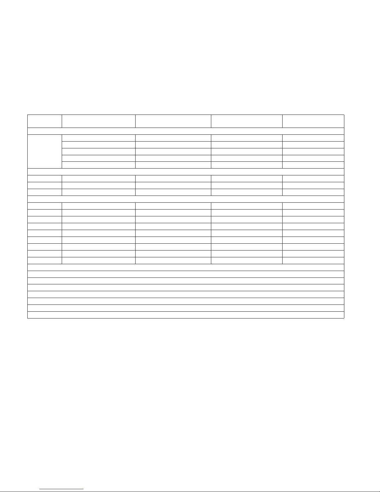
DIFFERENCES FROM BASE MODEL
LIST OF CHANGED PARTS
Ref. No. Description
PRINTED WIRING BOARD ASSEMBLIES
R/C, LED Unit DUNTKE868FM01 DUNTKE264FM02 Some parts changed
KEY Unit DUNTKE266FM02 ← —
MAIN Unit DUNTKE716FM02 DUNTKE716FM01 Some parts changed
POWER Unit RDENCA298WJQZ RDENCA295WJQZ —
LCD PANEL
42"LCD Panel Module Unit R1LK420D3LF21Z — Delete
46"LCD Panel Module Unit — R1LK460D3LW60Z Add
MAIN Unit
D1306 Photo Diode VHPGPFSV51V-1 VHPGPFSV51M-1 Change
IC1601 IC, BQC VHIS24CS02J5ES VHIS24CS02JBES Change
IC1602 IC, BQC VHIS24CS02J7ES VHIS24CS02JDES Change
IC1603 IC, BQC VHIS24CS02J6ES VHIS24CS02JCES Change
IC1801 IC, BQC VHIS24CS02J9ES VHIS24CS02JFES Change
IC1805 IC, BQC VHIS24CS02J8ES VHIS24CS02JEES Change
R601 Resistor VRS-CZ1JF000JY VRS-CZ1JF470JY Change
R602 Resistor VRS-CZ1JF000JY VRS-CZ1JF470JY Change
R/C, LED Unit
Please refer to a Parts list
CABINET AND MECHANICAL PARTS
Please refer to a Parts list
LC-42D65U
(No. S78N2LC42D65U)
LC-C4655U
(No. S08S2LCC4655U)
Note
PACKING PARTS AND ACCESSORIES
Please refer to a Parts list
i
LC-C4655U
LC-C4655U
SAFETY PRECAUTION
Service Manual
IMPORTANT SERVICE SAFETY PRECAUTION
Service work should be performed only by qualified service technicians who are thoroughly familiar with all safety checks and the
servicing guidelines which follow:
WARNING
1. For continued safety, no modification of any circuit should be
attempted.
2. Disconnect AC power before servicing.
CAUTION: FOR CONT I N U E D PROTECTION
AGAINST A RISK OF FIRE REPLACE ONLY WITH
SAME TYPE FUSE.
F7000 (250V T6.3AH)
BEFORE RETURNING THE RECEIVER (Fire &
Shock Hazard)
Before returning the receiver to the user, perform the following
safety checks:
3. Inspect all lead dress to make certain that leads are not pinched,
and check that hardware is not lodged between the chassis and
other metal parts in the receiver.
4. Inspect all protective devices such as non-metallic control knobs,
insulation materials, cabinet backs, adjustment and compartment
covers or shields, isolation resistor-capacitor networks, mechanical
insulators, etc.
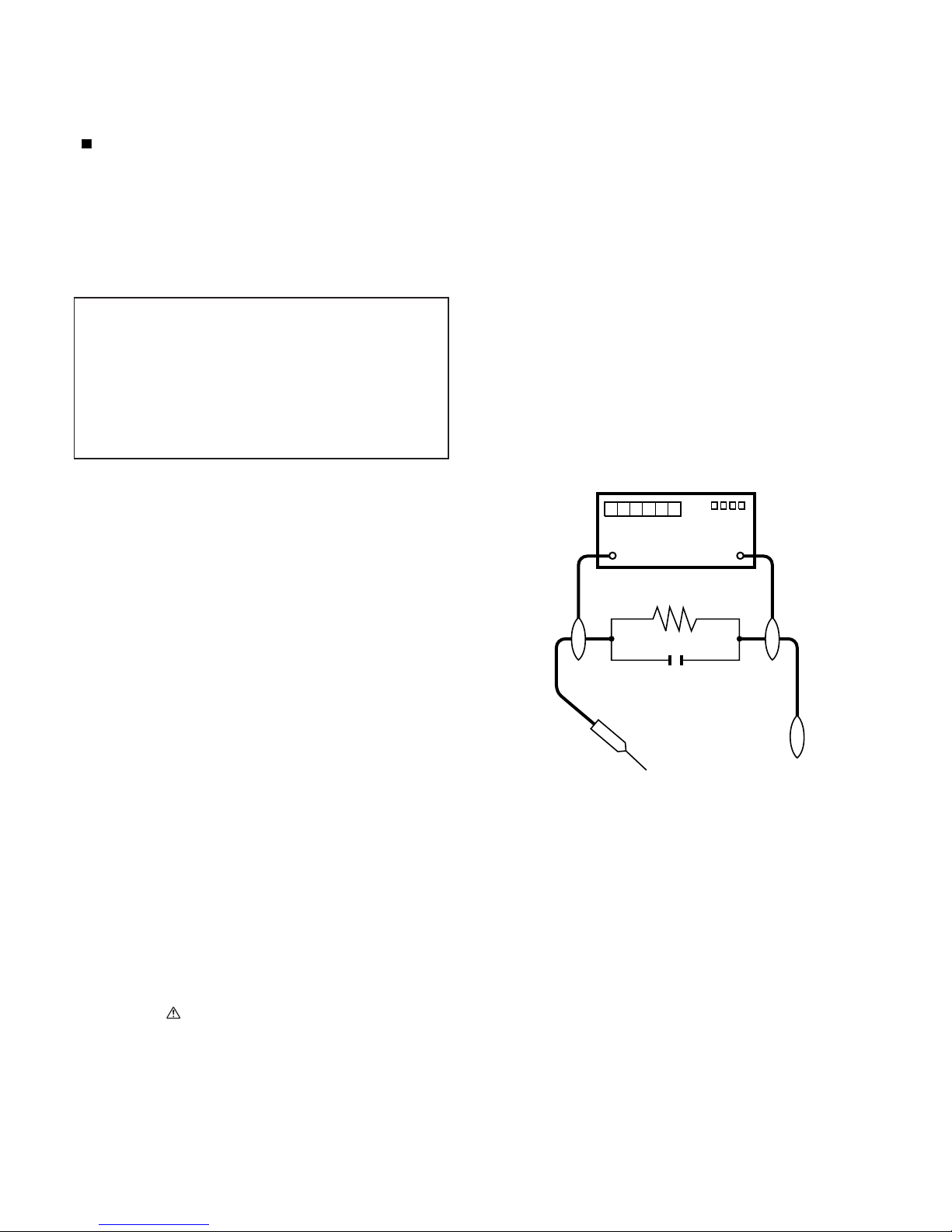
5. To be sure that no shock hazard exists, check for leakage current
in the following manner.
• Plug the AC cord directly into a 120 volt AC outlet.
(for North America)
• Plug the AC cord directly into a 110-240 volt AC outlet.
(for Others)
• Using two clip leads, connect a 1.5k ohm, 10 watt resistor paralleled by a 0.15µF capacitor in series with all exposed metal cabinet
parts and a known earth ground, such as electrical conduit or electrical ground connected to an earth ground.
• Use an AC voltmeter having with 5000 ohm per volt, or higher, sensitivity or measure the AC voltage drop across the resistor.
• Connect the resistor connection to all exposed metal parts having a
return to the chassis (antenna, metal cabinet, screw heads, knobs
and control shafts, escutcheon, etc.) and measure the AC voltage
drop across the resistor.
All checks must be repeated with the AC cord plug connection
reversed. (If necessary, a nonpolarized adaptor plug must be used
only for the purpose of completing these checks.)
Any reading of 0.75 Vrms (this corresponds to 0.5 mA rms AC.) or
more is excessive and indicates a potential shock hazard which
must be corrected before returning the monitor to the owner.
DVM
AC SCALE
1.5k ohm
10W
0.15µF
TEST PROBE
TO EXPOSED
METAL PARTS
CONNECT TO
KNOWN EARTH
GROUND
///////////////////////////////////////////////////////////////////////////////////////////////////////////////////////////////////////////////////////////////////////////////////////////////////////////////////////////////////////////
SAFETY NOTICE
Many electrical and mechanical parts in LCD color television have
special safety-related characteristics.
These characteristics are often not evident from visual inspection, nor
can protection afforded by them be necessarily increased by using
replacement components rated for higher voltage, wattage, etc.
Replacement parts which have these special safety characteristics are
identified in this manual; electrical components having such features
are identified by " " and shaded areas in the Replacement Parts List
and Schematic Diagrams.
///////////////////////////////////////////////////////////////////////////////////////////////////////////////////////////////////////////////////////////////////////////////////////////////////////////////////////////////////////////
For continued protection, replacement parts must be identical to those
used in the original circuit.
The use of a substitute replacement parts which do not have the same
safety characteristics as the factory recommended replacement parts
shown in this service manual, may create shock, fire or other hazards.
ii
LC-C4655U
PRECAUTIONS A PRENDRE LORS DE LA REPARATION
Ne peut effectuer la réparation qu' un technicien spécialisé qui s'est parfaitement accoutumé à toute vérification de sécurité et aux
conseils suivants.
•
AVERTISSEMENT
1.
N'entreprendre aucune modification de tout circuit. C'est dangereux.
2.
Débrancher le récepteur avant toute réparation.
PRECAUTION: POUR LA PROTECTION CONTINUE CONTRE LES RISQUES D'INCENDIE,
REMPLACER LE FUSIBLE
F7000 (250V T6.3AH)
VERIFICATIONS CONTRE L'INCEN-DIE ET LE
CHOC ELECTRIQUE
Avant de rendre le récepteur à l'utilisateur, effectuer les vérifications suivantes.
3.
Inspecter tous les faisceaux de câbles pour s'assurer que les fils
ne soient pas pincés ou qu'un outil ne soit pas placé entre le châssis et les autres pièces métalliques du récepteur.
4.
Inspecter tous les dispositifs de protection comme les boutons de
commande non-métalliques, les isolants, le dos du coffret, les couvercles ou blindages de réglage et de compartiment, les réseaux
de résistancecapacité, les isolateurs mécaniques, etc.
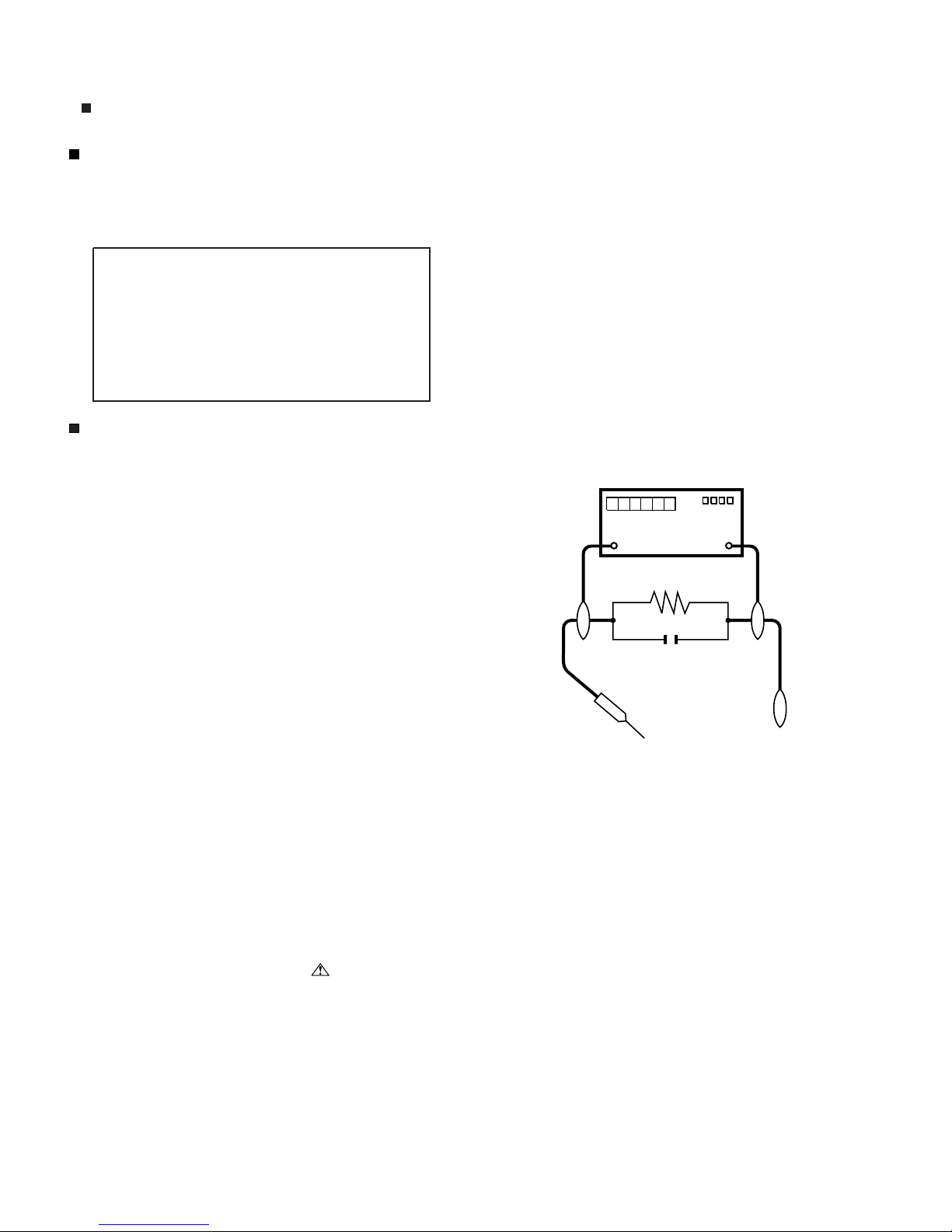
5.
S'assurer qu'il n'y ait pas de danger d'électrocution en vérifiant la
fuite de courant, de la facon suivante:
Brancher le cordon d'alimentation directem-ent à une prise de cou-
•
rant de 120V. (Ne pas utiliser de transformateur d'isolation pour
cet essai). (pour l'Amérique du Nord)
Brancher le cordon d'alimentation directem-ent à une prise de cou-
•
rant de 110-240V. (Ne pas utiliser de transformateur d'isolation
pour cet essai). (pour les autres régions)
A l'aide de deux fils à pinces, brancher une résistance de 1.5 kΩ
10 watts en parallèle avec un condensateur de 0.15µF en série
avec toutes les pièces métalliques exposées du coffret et une terre
connue comme une conduite électrique ou une prise de terre
branchée à la terre.
•
Utiliser un voltmètre CA d'une sensibilité d'au moins 5000Ω/V pour
mesurer la chute de tension en travers de la résistance.
•
Toucher avec la sonde d'essai les pièces métalliques exposées qui
présentent une voie de retour au châssis (antenne, coffret métallique, tête des vis, arbres de commande et des boutons, écusson,
etc.) et mesurer la chute de tension CA en-travers de la résistance.
Toutes les vérifications doivent être refaites après avoir inversé la
fiche du cordon d'alimentation. (Si nécessaire, une prise
d'adpatation non polarisée peut être utilisée dans le but de terminer ces vérifications.)
La tension de pointe mesurèe ne doit pas dépasser 0.75V (correspondante au courant CA de pointe de 0.5mA).
Dans le cas contraire, il y a une possibilité de choc électrique qui
doit être supprimée avant de rendre le récepteur au client.
DVM
ECHELLE CA
1.5k ohm
10W
µ
F
0.15
SONDE D'ESSAI
AUX PIECES
METALLIQUES
EXPOSEES
BRANCHER A UNE
TERRE CONNUE
/////////////////////////////////////////////////////////////////////////////////////////////////////////////////////////////////////////////////////////////////////////////////////////////////////////////////////////////////////////////
AVIS POUR LA SECURITE
De nombreuses pièces, électriques et mécaniques, dans les téléviseur ACL présentent des caractéristiques spéciales relatives à la sécurité, qui ne sont souvent pas évidentes à vue. Le degré de protection ne peut pas être nécessairement augmentée en utilisant des
pièces de remplacement étalonnées pour haute tension, puissance,
etc.
Les pièces de remplacement qui présentent ces caractéristiques sont
identifiées dans ce manuel; les pièces électriques qui présentent ces
particularités sont identifiées par la marque " " et hachurées dans la
liste des pièces de remplacement et les diagrammes schématiques.
/////////////////////////////////////////////////////////////////////////////////////////////////////////////////////////////////////////////////////////////////////////////////////////////////////////////////////////////////////////////
Pour assurer la protection, ces pièces doivent être identiques à celles
utilisées dans le circuit d'origine. L'utilisation de pièces qui n'ont pas
les mêmes caractéristiques que les pièces recommandées par l'usine,
indiquées dans ce manuel, peut provoquer des électrocutions, incendies, radiations X ou autres accidents.
iii
LC-C4655U
PRECAUTIONS FOR USING LEAD-FREE SOLDER
Employing lead-free solder
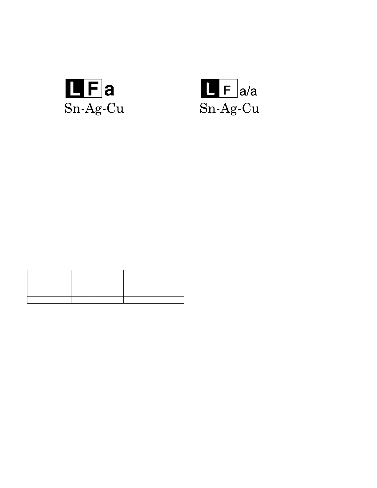
• “PWBs” of this model employs lead-free solder. The LF symbol indicates lead-free solder, and is attached on the PWBs and service manuals. The
alphabetical character following LF shows the type of lead-free solder.
Example:
Indicates lead-free solder of tin, silver and copper. Indicates lead-free solder of tin, silver and copper.
Using lead-free wire solder
• When fixing the PWB soldered with the lead-free solder, apply lead-free wire solder. Repairing with conventional lead wire solder may cause damage or accident due to cracks.
As the melting point of lead-free solder (Sn-Ag-Cu) is higher than the lead wire solder by 40 °C, we recommend you to use a dedicated soldering
bit, if you are not familiar with how to obtain lead-free wire solder or soldering bit, contact our service station or service branch in your area.
Soldering
• As the melting point of lead-free solder (Sn-Ag-Cu) is about 220 °C which is higher than the conventional lead solder by 40 °C, and as it has poor
solder wettability, you may be apt to keep the soldering bit in contact with the PWB for extended period of time. However, Since the land may be
peeled off or the maximum heat-resistance temperature of parts may be exceeded, remove the bit from the PWB as soon as you confirm the
steady soldering condition.
Lead-free solder contains more tin, and the end of the soldering bit may be easily corroded. Make sure to turn on and off the power of the bit as
required.
If a different type of solder stays on the tip of the soldering bit, it is alloyed with lead-free solder. Clean the bit after every use of it.
When the tip of the soldering bit is blackened during use, file it with steel wool or fine sandpaper.
• Be careful when replacing parts with polarity indication on the PWB silk.
Lead-free wire solder for servicing
PARTS CODE
ZHNDAi123250E BL J φ0.3mm 250g (1roll)
ZHNDAi126500E BK J φ0.6mm 500g (1roll)
ZHNDAi12801KE BM J φ1.0mm 1kg (1roll)
PRICE
RANK
PART
DELIVERY
DESCRIPTION
iv

LC-C4655U
PRECAUTIONS IN SERVICING THE HDCP-KEY ROM
Applied part: HDCP-KEY ROM
IC8451 RH-IXC318WJQZY (updated ROM)
The HDCP-KEY ROM shall be protected and managed for its information inside. In servicing this ROM, therefore, take the following information protection/management measures.
1) When disposing of the component parts and PWBs, destruct the IC itself in a proper way.
(For repairing or replacing the component parts and PWBs as well as clearing those in stock)
2) In storing the component parts, protect and manage them against theft and disclosure.
(For storing the service parts, service units, etc.)
v
LC-C4655U
CHAPTER 1. SPECIFICATIONS
[1] SPECIFICATIONS
LC-C4655U
Service Manual
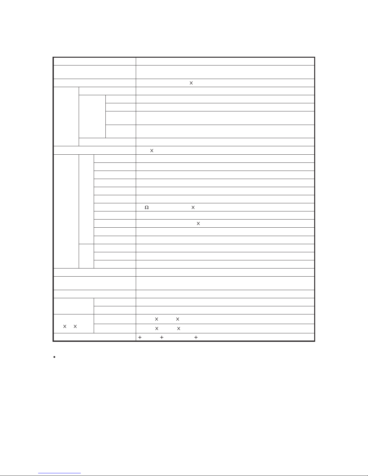
Item Model: LC-C4655U
63
/
LCD panel
46" Class (45
Advanced Super View & BLACK TFT LCD)
Diagonal)
"
64
Resolution 2,073,600 pixels (1,920 1,080)
TV-standard (CCIR) American TV Standard ATSC/NTSC System
VHF/UHF VHF 2-13ch, UHF 14-69ch
CATV 1-135ch (non-scrambled channel only)
TV
Function
Receiving
Channel
Digital Terrestrial
Broadcast (8VSB)
Digital cable
*1
(64/256 QAM)
2-69ch
1-135ch (non-scrambled channel only)
Audio multiplex BTSC System
Audio out 10W 2
INPUT 1 AV in, COMPONENT in
INPUT 2 COMPONENT in, S-VIDEO in
INPUT 4
ANALOG RGB (PC) in (15-pin mini D-sub female connector), Audio in (Ø 3.5 mm jack)
INPUT 6 HDMI in with HDCP, Audio in (Ø 3.5 mm jack)
INPUT 7 HDMI in with HDCP
INPUT 8 HDMI in with HDCP
Rear
Terminals
ANT/CABLE 75 Unbalance, F Type 1 for Analog (VHF/UHF/CATV) and Digital (AIR/CABLE)
AUDIO Audio in (Ø 3.5 mm jack)
DIGITAL AUDIO OUTPUT
Optical Digital audio output 1 (PCM/Dolby Digital)
OUTPUT Audio out
RS-232C 9-pin D-sub male connector
INPUT 3 AV in
Side
INPUT 5 HDMI in with HDCP
SERVICE Software update
OSD language English/French/Spanish
Power Requirement
AC 120 V, 60 Hz (FOR NORTH AMERICA)
AC 110-240 V, 50/60 Hz (FOR OTHERS)
Power Consumption 254 W (0.4 W Standby with AC 120 V)
Weight
Dimension
(W H D)
TV + stand 49.6 lbs./22.5 kg
TV only 41.9 lbs./19.0 kg
TV + stand 43
TV only 43
53
/64303/64131/2inch
53
/642747/64329/32inch
Operating temperature 32°F to 104°F (0°C to 40°C)
*1
Emergency alert messages via Cable are unreceivable.
As part of policy of continuous improvement, SHARP reserves the right to make design and specification changes for product
improvement without prior notice. The performance specification figures indicated are nominal values of production units.
There may be some deviations from these values in individual units.
1 – 1
LC-C4655U
LC-C4655U
CHAPTER 2. OPERATION MANUAL
[1] OPERATION MANUAL
Part Names
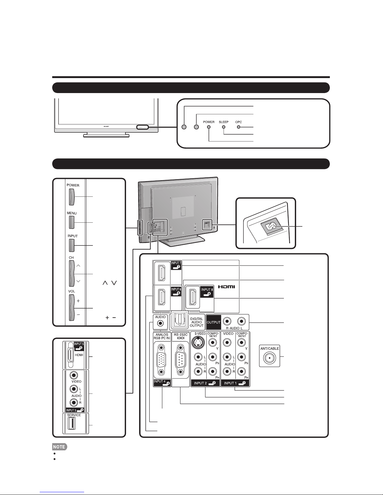
TV (Front)
* OPC: Optical Picture Control
TV (Rear/Side)
POWER
button
Service Manual
Remote control sensor
OPC sensor
OPC indicator
SLEEP indicator
POWER indicator
*
MENU
button
INPUT
button
Channel
buttons
(CH /)
Volume
buttons
(VOL /)
INPUT 5
terminal
(HDMI)
INPUT 3
terminals
SERVICE
terminal
AC INPUT
terminal
INPUT 7 terminal
(HDMI)
DIGITAL AUDIO
OUTPUT terminal
INPUT 8 terminal
(HDMI)
AUDIO OUTPUT
terminals
Antenna/Cable in
INPUT 1 terminals
INPUT 2 terminals
RS-232C terminal
INPUT 4 terminal (PC-IN)
AUDIO terminal (shared for INPUT 4 and INPUT 6)
INPUT 6 terminal (HDMI)
The illustrations in this operation manual are for explanation purposes and may vary slightly from the actual operations.
The examples used throughout this manual are based on the LC-C5255U model.
2 – 1
Part Names
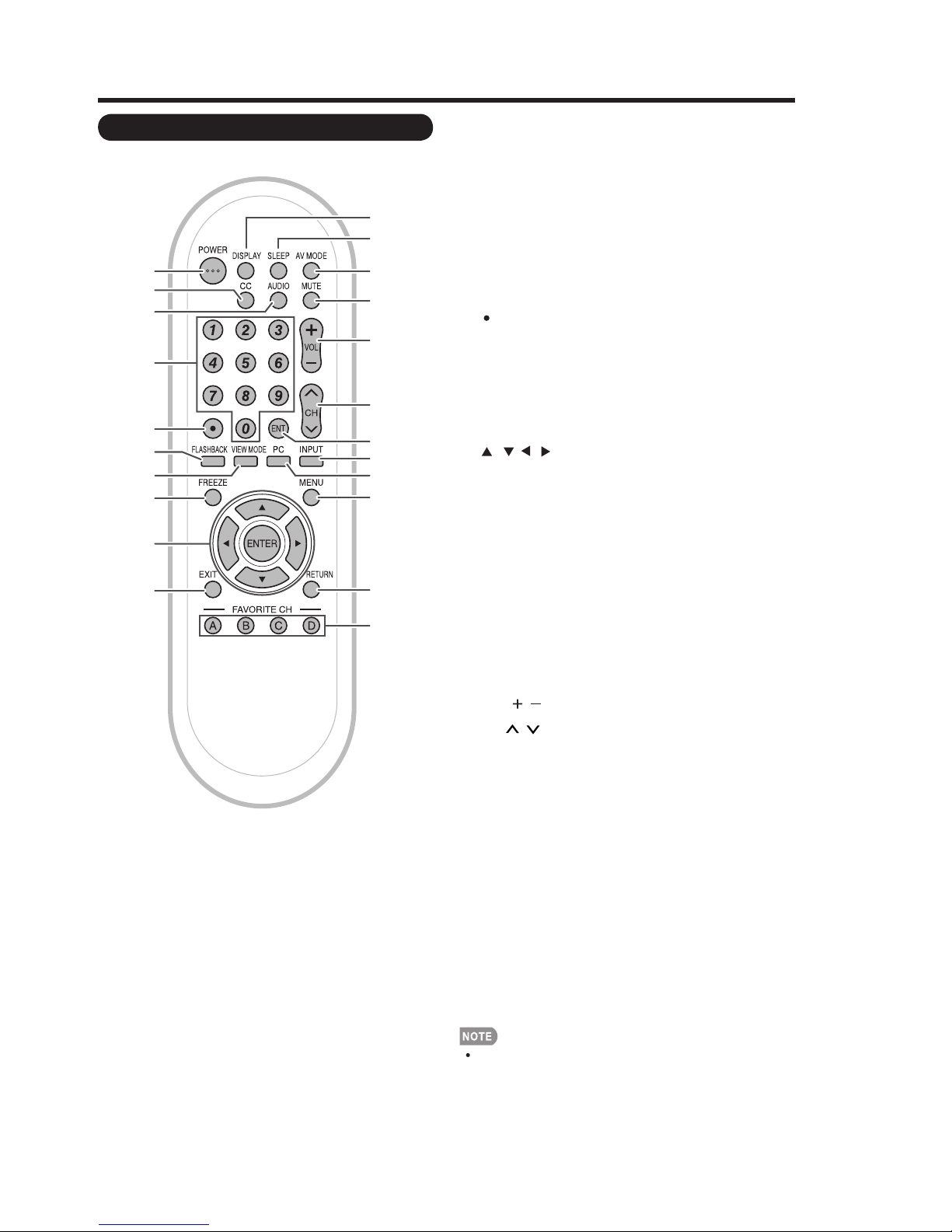
Remote Control Unit
1
2
3
4
5
6
7
8
9
10
11
12
13
14
15
16
17
18
19
20
21
22
LC-C4655U
1 POWER: Switch the TV power on or enters
standby.
2CC:Display captions from a closed-caption
source.
3 AUDIO: Selects the MTS/SAP or the audio mode
during multi-channel audio broadcasts.
40–9: Set the channel.
5(DOT):
6 FLASHBACK:Return to the previous channel or
external input mode.
7 VIEW MODE: Select the screen size.
8 FREEZE: Set the still image. Press again to return
to normal screen.
9 ///,ENTER: Select a desired item on the
screen.
10 EXIT: Turn off the menu screen.
11 DISPLAY: Display the channel information.
12 SLEEP: Set the sleep timer.
13 AV MODE: Select an audio or video setting.
(When the input source is TV, INPUT 1, 2 or 3:
STANDARD, MOVIE, GAME, USER, DYNAMIC (Fixed),
DYNAMIC. When the input source is INPUT 4, 5, 6 or 7:
STANDARD, MOVIE, GAME, PC, xvYCC (INPUT 4/5/6
only) USER, DYNAMIC (Fixed), DYNAMIC)
14 MUTE: Mute the sound.
15 VOL / : Set the volume.
16 CH / : Select the channel.
17 ENT: Jumps to a channel after selecting with the
0–9 buttons.
INPUT: Select a TV input source. (TV, INPUT 1,
18
INPUT 2, INPUT 3, INPUT 4, INPUT 5, INPUT 6, INPUT 7)
19 PC: Quickly access to PC mode.
20 MENU: Display the menu screen.
21 RETURN: Return to the previous menu screen.
22 FAVORITE CH
A, B, C, D: Select 4 preset favorite channels in 4
different categories.
While watching, you can toggle the selected
channels by pressing A, B, C and D.
When using the remote control unit, point it at the TV.
2 – 2
LC-C4655U
QUICK REFERENCE
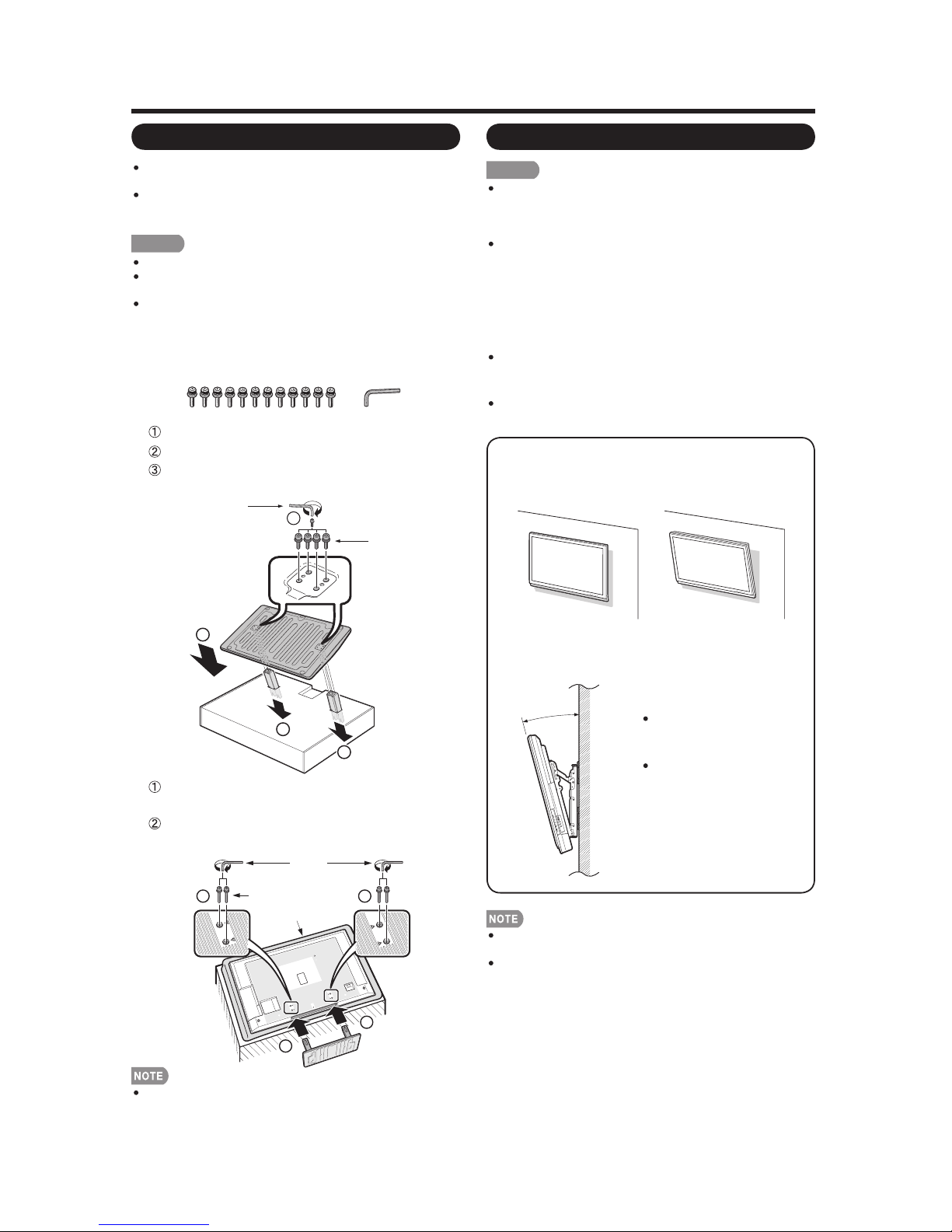
Attaching/Detaching the Stand
Before attaching (or detaching) the stand, unplug the AC
cord from the AC INPUT terminal.
Before performing work spread cushioning over the base
area to lay the TV on. This will prevent it from being
damaged.
CAUTION
Attach the stand in the correct direction.
Do not remove the stand from the TV unless using an
optional wall mount bracket to mount it.
Be sure to follow the instructions. Incorrect installation
of the stand may result in the TV falling over.
1 Confirm that there are 12 screws (all the same size)
and a hex key supplied with the stand unit.
2 Set the post for the stand unit onto the box.
Attach the base to the post.
Insert and tighten the 8 screws into the 8 holes
on the bottom of the base.
Hex key
3
Screws
Setting the TV on the Wall
CAUTION
This TV should be mounted on the wall only with the
AN-52AG4 (SHARP) wall mount bracket. The use of
other wall mount brackets may result in an unstable
installation and may cause serious injuries.
Installing the TV requires special skill that should
only be performed by qualified service personnel.
Customers should not attempt to do the work
themselves. SHARP bears no responsibility for
improper mounting or mounting that results in
accident or injury.
Using an optional bracket to mount the TV
You can ask a qualified service professional about
using an optional AN-52AG4 bracket to mount the TV
to the wall.
Carefully read the instructions that come with the
bracket before beginning work.
Hanging on the wall
AN-52AG4 wall mount bracket.
(See the bracket instructions for details.)
2
1
1
3 Insert the stand into the openings on the bottom
of the TV.
Insert and tighten the 4 screws into the 4 holes
on the rear of the TV.
Hex key
2 2
Screws
Soft cushion
1
1
Vertical mounting Angular mounting
About setting the TV angle
°
0
2
/
5
1
/
0
1
/
5
/
0
LC-C4655U
The "b" position is at the
center of the display.
Refer to the operation
manual of AN-52AG4 for
details.
Detach the cable clamp on the rear of the TV when using
the optional mount bracket.
To use this TV mounted on a wall, remove the covers at
the 4 locations on the rear of the TV, and then use the
screws supplied with the wall mount bracket to secure the
bracket to the rear of the TV.
To detach the stand, perform the steps in reverse order.
2 – 3
Appendix
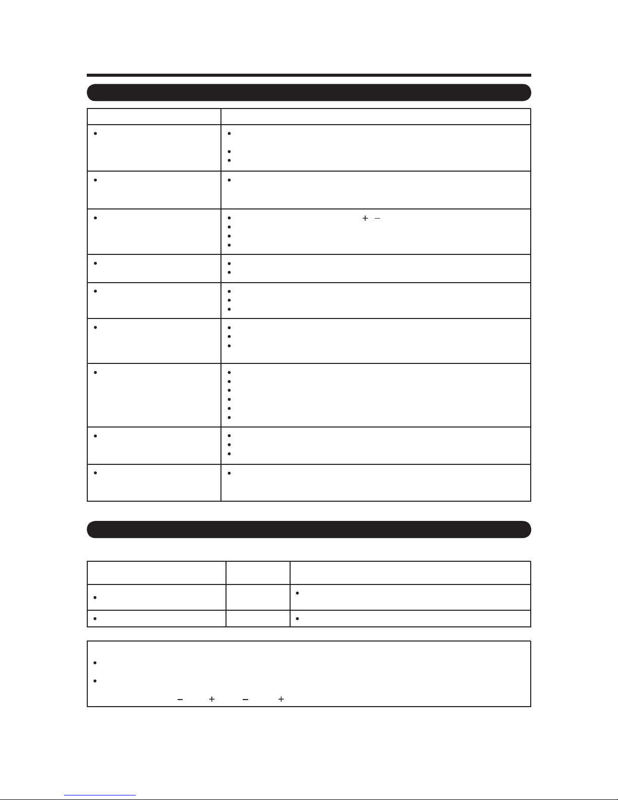
Troubleshooting
LC-C4655U
Problem
No power
Unit cannot be operated.
Remote control unit does not
operate.
Picture is cut off/with sidebar
screen.
Strange color, light color, or color
misalignment
Power is suddenly turned off.
No picture
Possible Solution
Check if you pressed POWER on the remote control unit.
If the indicator on the TV does not light up, press POWER on the TV.
Is the AC cord disconnected?
Has the power been turned on?
External influences such as lightning, static electricity, may cause improper operation.
In this case, operate the unit after first turning off the power of the TV or unplugging
the AC cord and replugging it in after 1 or 2 minutes.
Are batteries inserted with polarity ( , ) aligned?
Are batteries worn out? (Replace with new batteries.)
Are you using it under strong or fluorescent lighting?
Is a fluorescent light illuminated near the remote control sensor?
Is the image position correct?
Are screen mode adjustments such as picture size made correctly?
Adjust the picture tone.
Is the room too bright? The picture may look dark in a room that is too bright.
Check the input signal setting.
Is the sleep timer set?
Check the power control settings.
The unit's internal temperature has increased. Remove any objects blocking vent or
clean.
Is connection to other components correct?
Is correct input signal source selected after connection?
Is the correct input selected?
Is picture adjustment correct?
Is “On” selected in “Audio Only”?
Is a non-compatible signal being input?
No sound
The TV sometimes makes a
cracking sound.
Is the volume too low?
Is “Variable” selected in “Output Select”?
Have you pressed MUTE on the remote control unit?
This is not a malfunction. This happens when the cabinet slightly expands and
contracts according to change in temperature. This does not affect the TV's
performance.
Troubleshooting-Digital Broadcasting
The error message about reception of broadcast
The example of an error message
displayed on a screen
Failed to receive broadcast.
No broadcast now.
Error code
E202
E203 Check the broadcast time in the program guide.
Check the antenna cable. Check that the antenna is correctly
setup.
Possible Solution
Cautions regarding use in high and low temperature environments
When the unit is used in a low temperature space (e.g. room, office), the picture may leave trails or appear slightly delayed
This is not a malfunction, and the unit will recover when the temperature returns to normal.
Do not leave the unit in a hot or cold location. Also, do not leave the unit in a location exposed to direct sunlight or near a
heater, as this may cause the cabinet to deform and the Liquid Crystal panel to malfunction.
Storage temperature: 4°F to 140°F (
20°C to 60°C)
.
2 – 4

LC-C4655U
On-Screen Display Menu
Menu Items
For TV/INPUT 1/2/3 Mode
Picture Menu
OPC
Backlight
Contrast
Brightness
Color
Tint
Sharpness
Advanced
C.M.S.-Hue
C.M.S.-Saturation
Color Temp.
Active Contrast
I/P Setting
Film Mode
Digital Noise Reduction
3D-Y/C
Monochrome
Range of OPC
Reset
Audio Menu
Treble
Bass
Balance
Surround
Bass Enhancer
Reset
Power Control Menu
Power Saving
No Signal Off
No Operation Off
Setup Menu
EZ Setup
CH Setup
Antenna Setup-DIGITAL
Input Skip
Input Label
Parental CTRL
Position
Language
Reset
For HDMI/PC-IN Mode
Picture Menu
OPC
Backlight
Contrast
Brightness
Color
Tint
Sharpness
Advanced
C.M.S.-Hue
C.M.S.-Saturation
Color Temp.
Active Contrast
I/P Setting
Film Mode
Digital Noise Reduction
Monochrome
Range of OPC
Reset
Audio Menu
Treble
Bass
Balance
Surround
Bass Enhancer
Reset
Power Control Menu
Power Saving
No Signal Off
No Operation Off
Setup Menu
Input Skip
Input Signal
Auto Sync.
Input Label
Fine Sync.
Position
Language
Reset
Option Menu
Audio Only
Input Select
PC Audio Select
Output Select
Color System
Caption Setup
Digital Caption Info. .
Program Title Display
Favorite CH
Game Play Time
Operation Lock Out
Digital Setup Menu
Audio Setup
Identification
Software Update
Option Menu
Audio Only
HDMI Setup
PC Audio Select
Output Select
Game Play Time
Operation Lock Out
Digital Setup Menu
Software Update
Some menu items may not be displayed depending on the selected input source.
2 – 5
LC-C4655U
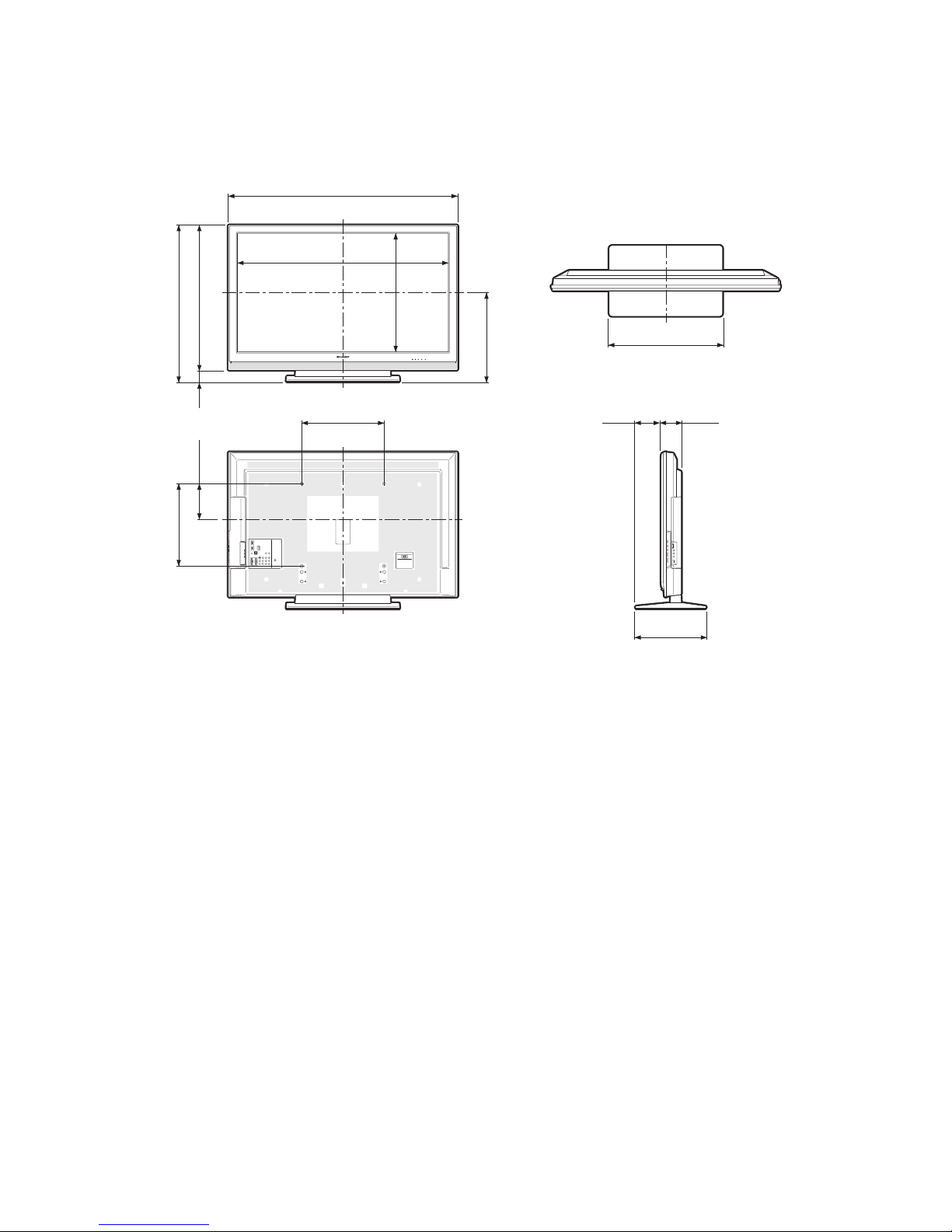
CHAPTER 3. DIMENSIONS
[1] DIMENSIONS
53
/64(1113)
43
19
/64(1023.4)
40
(704)
(763)
64
64
/
/
3
47
30
27
64
/
21
(59)
2
8
/
7
6
(174.3)
153/4(400)
64
/
43
22
(575.6)
Service Manual
(435)
64
/
9
17
457/
(124)
2121/32(550)
64
Unit: inch (mm)
29
/
3
32
(99)
LC-C4655U
(400)
4
/
3
15
131/2(343)
3 – 1
LC-C4655U
LC-C4655U
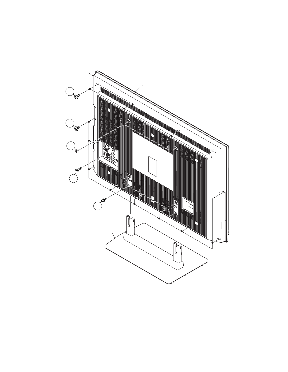
CHAPTER 4. REMOVING OF MAJOR PARTS
Service Manual
[1] REMOVING OF MAJOR PARTS
1. Remove the 4 lock screws and detach the Stand.
2. Remove the 4 VESA Hole Covers.
3. Remove the 1 lock screw.
4. Remove the 4 lock screws, 9 lock screws and detach the Rear Cabinet.
Rear Cabinet
Front Cabinet
4
4
2
3
1
Stand
4 – 1
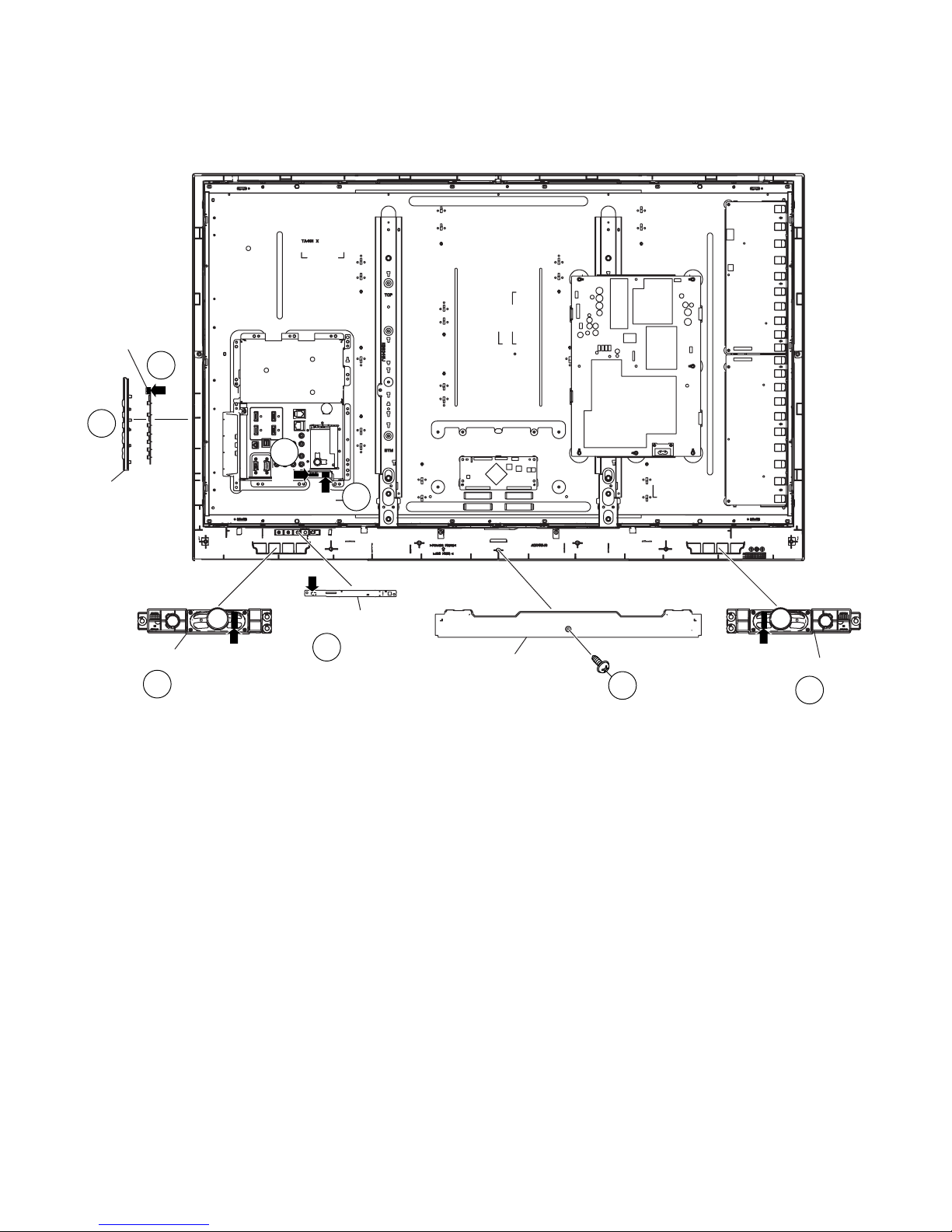
5. Remove the 1 lock screw and detach the Bottom Cover.
6. Disconnect SP-Wire and detach the Speaker-LR.
7. Detach the R/C, LED Unit, and disconnect RA-Wire.
8. Detach the KEY Unit Ass'y.
9. Detach the KEY Unit from the KEY Button Cover, and disconnect KM-Wire.
KEY Unit
9
KM
8
7
RA
KEY Button
Cover
SP
6
LC-C4655U
Speaker-R
6
SP
RA
R/C, LED Unit
7
Bottom Cover
SP
Speaker-L
5
6
4 – 2
 Loading...