

LC-52XS1E/RU/LC-65XS1E/RU
LC-52XS1E
CHAPTER 1. OPERATION MANUAL
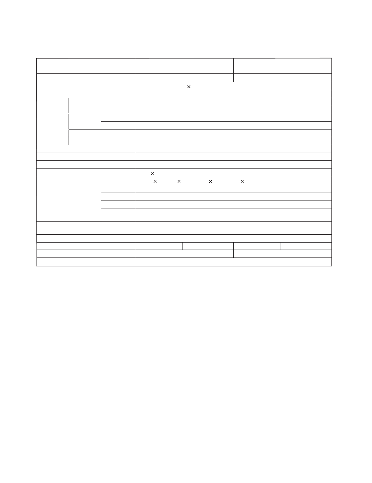
[1] SPECIFICATIONS
Service Manual
Item
LCD panel
Resolution
Video Colour System PAL/SECAM/NTSC 3.58/NTSC 4.43/PAL 60
TV Function TV-Standard Analogue CCIR (B/G, I, D/K, L/L’)
Digital DVB-T (2K/8K OFDM), DVB-C, S/S2
Receiving
Channel
TV-Tuning System Auto Preset 999 ch: non-Nordic / 9999 ch: Nordic (ATV: 99 ch), Auto Label, Auto Sort
STEREO/BILINGUAL NICAM/A2
Brightness 450 cd/m
Backlight life 60,000 hours (when "Backlight" is set to the default position)
Viewing angles H: 176°, V: 176°
Audio amplifier
Speaker
Terminal (Display) USB USB 2.0
OSD language
Power Requirement AC 220–240 V, 50 Hz
Power Consumption
Weight 45.0 kg (Display) 62.5 kg (Display)
Operating temperature
•
As a part of our policy of continuous improvement, SHARP reserves the right to make design and specification changes for product improvement without prior
notice. The performance specification figures indicated are nominal values of production units. There may be some deviations from these values in individual units.
(Method IEC62087)
VHF/UHF E2–E69 ch, F2–F10 ch, I21–I69 ch, IR A–IR J ch (Digital: IR A ch–E69 ch)
CATV Hyper-band, S1–S41 ch
DISPLAY INPUT
DC OUTPUT DC 5V, 1.8A MAX
SPEAKER
OUTPUT
52" LCD COLOUR TV, Model: LC52XS1E (Display)
52" Advanced Super View & BLACK TFT LCD 65" Advanced Super View & BLACK TFT LCD
2,073,600 pixels (1,920 1,080)
2
7.5 W 2, 15 W (subwoofer)
50 mm 120 mm 2, Ø 26 mm 2, Ø 77 mm 1
HDMI
L/R, WOOFER
Czech, Danish, Dutch, English, Estonian, Finnish, French, German, Greek, Hungarian, Italian, Latvian,
Lithuanian, Norwegian, Polish, Portuguese, Russian, Slovak, Slovene, Spanish, Swedish, Turkish, Ukrainian
LC-52XS1E 294 W (1.0 W Standby) LC-65XS1E
0°Cto+40°C
65" LCD COLOUR TV, Model: LC-
65XS1E (Display)
512 W (1.0 W Standby)
NOTE
Refer to the inside back cover for dimensional drawings.
•
1 – 1
[2] OPERATION MANUAL
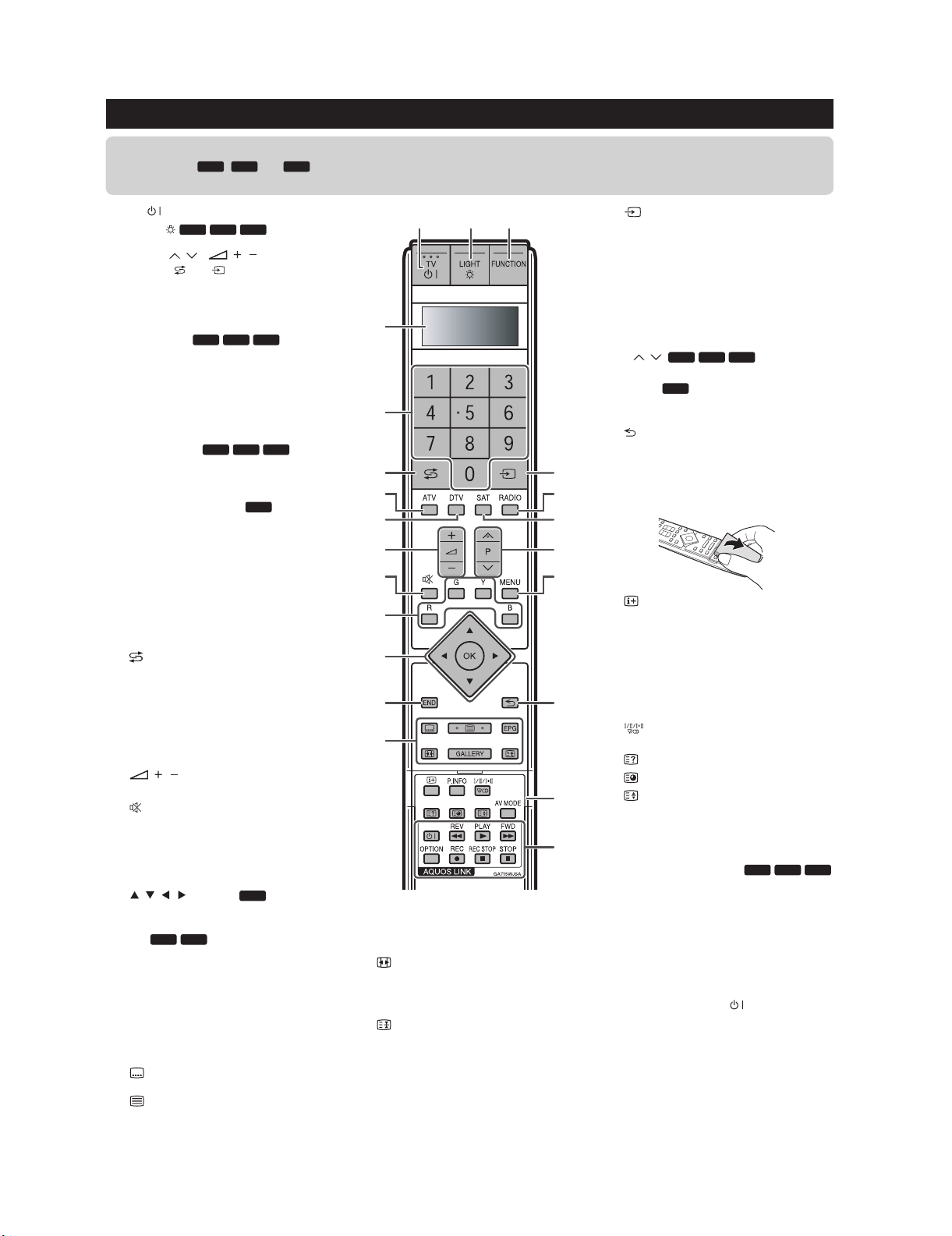
Remote control unit
LC-52XS1E/RU/LC-65XS1E/RU
NOTE
The symbols , and indicate that the buttons become available in respective operating mode when using as a universal
•
remote control.
TV (TV Standby/On)
1
LIGHT
2
When pressed, buttons that are frequently
used (P /, /,0–9 numeric
buttons, and ) will light. The light
will turn off if no operations are performed
within about five seconds. This button is
used for performing operations in low-light
situations.
FUNCTION
3
Press this button briefly (for more than 0.2
second), and the remote control switches
for DVD, SetTopBox or VCR operation
and currently controlled devices will be
indicated in the LCD window.
LCD window
4
This screen shows which device you are
currently controlling (TV, DVD, STB or
VCR).
0–9 numeric buttons
5
Set the channel.
Enter desired numbers.
Set the page in teletext mode.
When the five Nordic countries
•
(Sweden, Norway, Finland, Denmark,
or Iceland) are selected in the country
setting from “Auto Installation”,
DTV services are four digits. When
another country is selected, DTV
services are three digits.
(Flashback)
6
Press to return to the previously selected
channel or external input.
ATV
7
Press to access conventional analogue
TV mode.
DTV
8
Press to access digital TV mode.
9
Increase/decrease TV volume.
10
(Mute)
TV sound on/off.
11
R/G/Y/B (Colour) buttons
The coloured buttons are correspondingly
used to select the coloured items on the
screen (e.g. EPG, MHEG-5, Teletext).
12
/ / / (Cursor)
Select a desired item on the setting
screen.
DVD STB
OK
Execute a command within the “MENU”
screen.
ATV/DTV/SAT: Display the programme list
when no other “MENU” screen is running.
13
END
Exit the “MENU” screen.
14
Buttons for teletext and other useful
features
(Subtitle)
Switch subtitle languages on/off.
(Teletext)
ATV: Display analogue teletext.
DTV/SAT: Select MHEG-5 and teletext for
DTV/SAT.
DVD STB VCR
DVD STB VCR
DVD STB VCR
DVD STB
/(Volume)
STB
DVD
VCR
1
23
4
5
6
7
8
9
10
11
12
13
14
EPG
DTV/SAT: Display the EPG screen.
(WIDE MODE)
Select a wide mode.
GALLERY
Press to enter the Gallery Mode.
(Freeze/Hold)
Press to freeze a moving image on the
screen.
Teletext: Stop updating teletext pages
automatically or release the hold mode.
15
16
17
18
19
20
21
22
15
16
17
18
19
20
21
22
(INPUT SOURCE)
Select an input source.
RADIO
DTV/SAT: Switch between Radio and
Data mode.
When only data broadcasting (no radio
•
broadcasting) is transmitted by DVB,
the radio broadcasting will be skipped.
SAT
Press to access satellite mode.
DVD
P/
Select the TV channel.
MENU
ATV/DTV/SAT: “MENU” screen on/off.
DVD: Title menu on/off.
(Return)
Return to the previous “MENU” screen.
Buttons for teletext and other useful
features
Flip open the remote control cover on
the front.
(Display information)
Press to display the station information
(channel number, signal, etc.) in the upper
right corner of the screen.
P. INFO
Press to display programme information
which is transmitted through digital video
broadcasting in the u pper left corner of
the screen (DTV/SAT only).
(Sound mode)
Select a sound multiplex mode.
(Reveal hidden Teletext)
(Subpage)
(Top/Bottom/Full)
Set the area of magnification in teletext
mode.
AV MODE
Select a video setting.
AQUOS LINK buttons
TV mode: If external equipment such as a
AQUOS BD Player is connected via HDMI
cables and is AQUOS LINK compatible,
you can use these AQUOS LINK buttons.
DVD/VCR mode: Press OPTION to pause
the picture.
The buttons except OPTION are
•
correspondingly used to select the
items on the screen.
STB mode: Only the button can be
used to operate on STB.
STB VCR
DVD
DVD STB VCR
1 – 2

LC-52XS1E/RU/LC-65XS1E/RU
Part name
Display (Front view/Side view)
12345 69
1
2
3
4
5
/ Volume buttons*
P / Programme (channel)
buttons*
(INPUT SOURCE) button*
MENU button*
(Main Power) button*
Remote control sensor
6
7
8
9
10
11
(Standby/On) indicator
SLEEP indicator
OPC indicator
RESET button
USB terminal
The symbols light up when pressing these buttons. After a
*
period of time, the light will turn off.
78
AVC System (Front view/Rear view)
321 4 5 6 7 8
COMMON INTERFACE 1/2 slot
1
2
(Power) button
(Standby/On) indicator
3
RESET button
4
HDMI3 (HDMI) terminal
5
WARNING
Excessive sound pressure from earphones and headphones can cause hearing loss.
•
Do not set the volume at a high level. Hearing experts advise against extended listening at high volume levels.
•
EXT4 (ANALOGUE RGB/AUDIO)
6
terminals
EXT8 terminals
7
Headphones
8
10
11
11
9
10
EXT1 (RGB) terminal
9
EXT2 (RGB) terminal
10
EXT3 (COMPONENT/AUDIO)
11
terminals
OUTPUT (AUDIO) terminals
12
AVC System (Bottom view)
12 13 14 15
16
SAT (satellite) antenna terminal
13
Antenna terminal
14
DC OUTPUT terminal
15
DIGITAL AUDIO OUTPUT terminal
16
HDMI1 (HDMI/AUDIO) terminals
17
17 18 19 20 21 22
HDMI2 (HDMI) terminal
18
RS-232C terminal
19
USB terminal
20
DISPLAY OUTPUT terminal
21
AC INPUT terminal
22
Product label is on the bottom of the
AVC System.
1 – 3

LC-52XS1E/RU/LC-65XS1E/RU
Before turning on the main power
Preparing the Display
Make sure the Display is turned off before beginning work.
•
Before performing work, spread cushioning over the surface on which you will be laying the Display. This will
•
prevent it from being damaged.
Connecting the HDMI cable with the HDMI cable holder
HDMI cable
Speaker cable*
Press down on the
1 Connect the HDMI cable to
upper hook and remove
the rear terminal cover,
pulling towards you.
(supplied)
2 Affix the HDMI cable
the Display.
3
holder by pressing down.
HDMI cable
holder
(supplied)
NOTE
These are terminals for the speaker of the TV. Do not connect any other kind of cables.
*
Do not disconnect the speaker cable unless absolutely necessary. If you disconnect the speaker cable, confirm each colour
•
of the speaker plugs and speaker terminals (the order of the colour from left to right: red/black/white) before connecting the
speaker cable again.
Mounting the Display on a wall
This Display should be mounted on a wall only with the wall mount bracket available from SHARP.
•
The use of other wall mount brackets may result in an unstable installation and may cause
serious injuries.
•
Mounting the Display requires special skills and should only be performed by qualified service
personnel. Customers should not attempt to do the work themselves. SHARP bears no responsibility
for improper mounting or mounting that results in accident or injury.
•
You can ask qualified service personnel about using an optional bracket to mount the Display to a wall.
•
To use this Display mounted on a wall, first remove the adhesive tape at the two locations on the rear of the
Display
Display
, and then use the screws supplied with the wall mount bracket to secure the bracket to the rear of the
.
When using wall mount bracket AN-52AG8 or AN-65AG2
You can check the centre of the TV screen using the mark engraved on the wall mount bracket when mounting
the Display on the wall.
LC-52XS1E: The centre of the TV screen is at mark “E” on the wall bracket.
LC-65XS1E: The centre of the TV screen is at mark “A” on the wall bracket.
Setting the Display with the optional stand
This Display should be set on a table or floor, etc. only with the stand available from SHARP, sold separately.
•
Be sure to follow the instructions for the stand manual.
•
1 – 4

LC-52XS1E/RU/LC-65XS1E/RU
Setting the TV and antenna cables
Supplying power to the antenna
You must supply power to the antenna in order to receive digital terrestrial broadcasts or satellite broadcasts
after running the initial auto installation. Go to “MENU” > “Setup” > “Antenna Setup-DIGITAL” > “Digital Setup”
> “Supply Voltage” > select “On”.
NOTE
The indicator of the AVC System lights up when the main power is turned on after connecting the Display and AVC System using the
•
supplied HDMI cable.
The HDMI cable should be firmly connected. Failure to do so will loosen the cable and cause a contact failure when moving the AVC System.
•
This can cause result in an error message appearing on the screen without a visible picture.
Satellite antenna
cable
Connecting the HDMI cable with the
Standard
DIN45325 plug
(IEC 169-2) 75
coaxial cable
HDMI cable (supplied)
fixture/cushion
13
4 5
2
Tab
Do not use excessive
force when insering/
removing the HDMI
cable. The terminal or
cable may become
dameged.
Insert the fixture for
1
the HDMI cable into
the hole below the
DISPLAY OUTPUT
terminal on the AVC
System.
Detach the parts
2
of the fixture
while holding the
tab of the fixture
downward.
Wrap the cushion
3
around the HDMI
cable.
Attach the parts of
4 Connect the HDMI
the fixture on the
cushion, pushing the
tab downward.
5
cable with the fixture
to the DISPLAY
OUTPUT terminal
while sliding on the
bar of the fixture.
Handling the AVC System
CAUTION
Do not put a VCR or other device on top of the AVC System.
•
Keep enough space above and to the sides of the AVC
•
System.
Do not block the ventilation openings on the top and left side or
•
the exhaust fan on the right side.
Do not spread a thick cloth beneath the AVC System or cover it with one, as this can cause overheating and result in
•
malfunction.
1 – 5
5cm
5cm 5cm

[3] DIMENSIONS
(1528.0) / [1243.0]
(1429.0) / [1156.0]
LC-52XS1E/RU/LC-65XS1E/RU
Unit: mm
54.0
47.1
22.8
(1046.0 ) / [878.0]
(933.0) / [765.0]
113.0
(314.0)
(804.0) / [652.0]
(597.6) / [511.0]
(1312.0)/[1075.0]
60.4
400.0
[ 2 00.0 ]
( ) : LC-65XS1E/RU
[ ] : LC-52XS1E/RU
: LC-52XS1E/RU/65XS1E/RU
1 – 6
 Loading...