

Sharp LC-52D62U,LC-46D62U Service Manual
TopPage
LC-46D62U/LC-52D62U
SERVICE MANUAL
No. S86V8LC52D62U
LCD COLOR TELEVISION
LC-46D62U
MODELS
In the interests of user-safety (Required by safety regulations in some countries) the set should be restored to its orig-
In the interests of user-safety (Required by safety regulations in some countries) the set should be restored to its original condition and only parts identical to those specified should be used.
inal condition and only parts identical to those specified should be used.
LC-52D62U
CONTENTS
SAFETY PRECAUTION
IMPORTANT SERVICE SAFETY PRE-
CAUTION ............................................................i
PRECAUTIONS A PRENDRE LORS DE
LA REPARATION............................................... ii
PRECAUTIONS FOR USING LEAD-FREE
SOLDER ........................................................... iii
CHAPTER 1. SPECIFICATIONS
[1] SPECIFICATIONS ......................................... 1-1
CHAPTER 2. OPERATION MANUAL
[1] OPERATION MANUAL .................................. 2-1
CHAPTER 3. DIMENSIONS
[1] DIMENSIONS ................................................ 3-1
CHAPTER 7. MAJOR IC INFORMATIONS
[1] MAJOR IC INFORMATIONS .........................7-1
CHAPTER 8. OVERALL WIRING DIAGRAM/BLOCK
DIAGRAM
[1] OVERALL WIRING DIAGRAM ......................8-1
[2] SYSTEM BLOCK DIAGRAM .........................8-3
[3] MAIN BLOCK DIAGRAM............................... 8-5
CHAPTER 9. PRINTED WIRING BOARD
[1] R/C, LED UNIT PRINTED WIRING
BOARD.......................................................... 9-1
[2] KEY UNIT PRINTED WIRING BOARD .........9-2
[3] MAIN UNIT PRINTED WIRING BOARD........9-3
[4] TERMINAL UNIT PRINTED WIRING
BOARD........................................................ 9-11
CHAPTER 4. REMOVING OF MAJOR PARTS
[1] REMOVING OF MAJOR PARTS
(LC-46D62U).................................................. 4-1
[2] REMOVING OF MAJOR PARTS
(LC-52D62U).................................................. 4-6
CHAPTER 5. ADJUSTMENT
[1] ADJUSTMENT PROCEDURE ....................... 5-1
CHAPTER 6. TROUBLE SHOOTING TABLE
[1] TROUBLE SHOOTING TABLE...................... 6-1
Parts marked with " " are important for maintaining the safety of the set. Be sure to replace these parts with specified ones for maintaining the
safety and performance of the set.
CHAPTER 10. SCHEMATIC DIAGRAM
[1] DESCRIPTION OF SCHEMATIC DIA-
GRAM.......................................................... 10-1
[2] SCHEMATIC DIAGRAM ..............................10-2
Parts Guide
This document has been published to be used for
after sales service only.
The contents are subject to change without notice.
LC-46D62U/LC-52D62U
i
LC-46D62U
Service Manual
SAFETY PRECAUTION
IMPORTANT SERVICE SAFETY PRECAUTION
WARNING
1. For continued safety, no modification of any circuit should be
attempted.
2. Disconnect AC power before servicing.
BEFORE RETURNING THE RECEIVER (Fire &
Shock Hazard)
Before returning the receiver to the user, perform the following
safety checks:
3. Inspect all lead dress to make certain that leads are not pinched,
and check that hardware is not lodged between the chassis and
other metal parts in the receiver.
4. Inspect all protective devices such as non-metallic control knobs,
insulation materials, cabinet backs, adjustment and compartment
covers or shields, isolation resistor-capacitor networks, mechanical
insulators, etc.
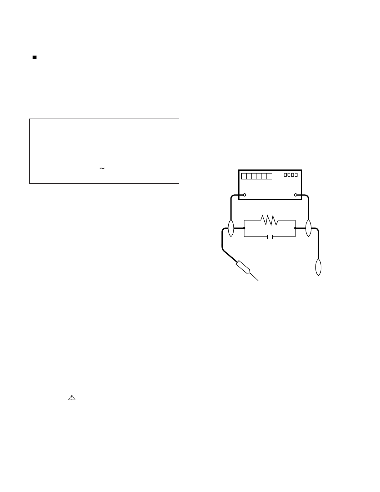
5. To be sure that no shock hazard exists, check for leakage current in
the following manner.
• Plug the AC cord directly into a 120 volt AC outlet.
• Using two clip leads, connect a 1.5k ohm, 10 watt resistor paralleled by a 0.15µF capacitor in series with all exposed metal cabinet
parts and a known earth ground, such as electrical conduit or electrical ground connected to an earth ground.
• Use an AC voltmeter having with 5000 ohm per volt, or higher, sensitivity or measure the AC voltage drop across the resistor.
• Connect the resistor connection to all exposed metal parts having a
return to the chassis (antenna, metal cabinet, screw heads, knobs
and control shafts, escutcheon, etc.) and measure the AC voltage
drop across the resistor.
All checks must be repeated with the AC cord plug connection
reversed. (If necessary, a nonpolarized adaptor plug must be used
only for the purpose of completing these checks.)
Any reading of 0.75 Vrms (this corresponds to 0.5 mA rms AC.) or
more is excessive and indicates a potential shock hazard which
must be corrected before returning the monitor to the owner.
///////////////////////////////////////////////////////////////////////////////////////////////////////////////////////////////////////////////////////////////////////////////////////////////////////////////////////////////////////////
SAFETY NOTICE
Many electrical and mechanical parts in LCD color television have
special safety-related characteristics.
These characteristics are often not evident from visual inspection, nor
can protection afforded by them be necessarily increased by using
replacement components rated for higher voltage, wattage, etc.
Replacement parts which have these special safety characteristics are
identified in this manual; electrical components having such features
are identified by " " and shaded areas in the Replacement Parts
List and Schematic Diagrams.
For continued protection, replacement parts must be identical to those
used in the original circuit.
The use of a substitute replacement parts which do not have the same
safety characteristics as the factory recommended replacement parts
shown in this service manual, may create shock, fire or other hazards.
///////////////////////////////////////////////////////////////////////////////////////////////////////////////////////////////////////////////////////////////////////////////////////////////////////////////////////////////////////////
Service work should be performed only by qualified service technicians who are thoroughly familiar with all safety checks and the
servicing guidelines which follow:
CAUTION: FOR CONTINUED PROTECTION
AGAINST A RISK OF FIRE REPLACE ONLY WITH
SAME TYPE FUSE.
F701 (250V 8A), F702 (250V 1A)
F4702 (250V 4A),
F4701/F4703 (250V 3A 127
O
C)
DVM
AC SCALE
1.5k ohm
10W
TO EXPOSED
METAL PARTS
CONNECT TO
KNOWN EARTH
GROUND
0.15µF
TEST PROBE
LC-46D62U/LC-52D62U
ii
PRECAUTIONS A PRENDRE LORS DE LA REPARATION
De nombreuses pièces, électriques et mécaniques, dans les téléviseur ACL présentent des caractéristiques spéciales relatives à la sécurité, qui ne sont souvent pas évidentes à vue. Le degré de protection ne peut pas être nécessairement augmentée en utilisant des
pièces de remplacement étalonnées pour haute tension, puissance,
etc.
Les pièces de remplacement qui présentent ces caractéristiques sont
identifiées dans ce manuel; les pièces électriques qui présentent ces
particularités sont identifiées par la marque " " et hachurées dans la
liste des pièces de remplacement et les diagrammes schématiques.
Pour assurer la protection, ces pièces doivent être identiques à celles
utilisées dans le circuit d'origine. L'utilisation de pièces qui n'ont pas
les mêmes caractéristiques que les pièces recommandées par l'usine,
indiquées dans ce manuel, peut provoquer des électrocutions, incendies, radiations X ou autres accidents.
AVERTISSEMENT
1.
2.
3.
4.
5.
•
•
•
•
/////////////////////////////////////////////////////////////////////////////////////////////////////////////////////////////////////////////////////////////////////////////////////////////////////////////////////////////////////////////
/////////////////////////////////////////////////////////////////////////////////////////////////////////////////////////////////////////////////////////////////////////////////////////////////////////////////////////////////////////////
Ne peut effectuer la réparation qu' un technicien spécialisé qui s'est parfaitement accoutumé à toute vérification de sécurité et aux
conseils suivants.
N'entreprendre aucune modification de tout circuit. C'est dangereux.
Débrancher le récepteur avant toute réparation.
Inspecter tous les faisceaux de câbles pour s'assurer que les fils
ne soient pas pincés ou qu'un outil ne soit pas placé entre le châssis et les autres pièces métalliques du récepteur.
Inspecter tous les dispositifs de protection comme les boutons de
commande non-métalliques, les isolants, le dos du coffret, les couvercles ou blindages de réglage et de compartiment, les réseaux
de résistancecapacité, les isolateurs mécaniques, etc.
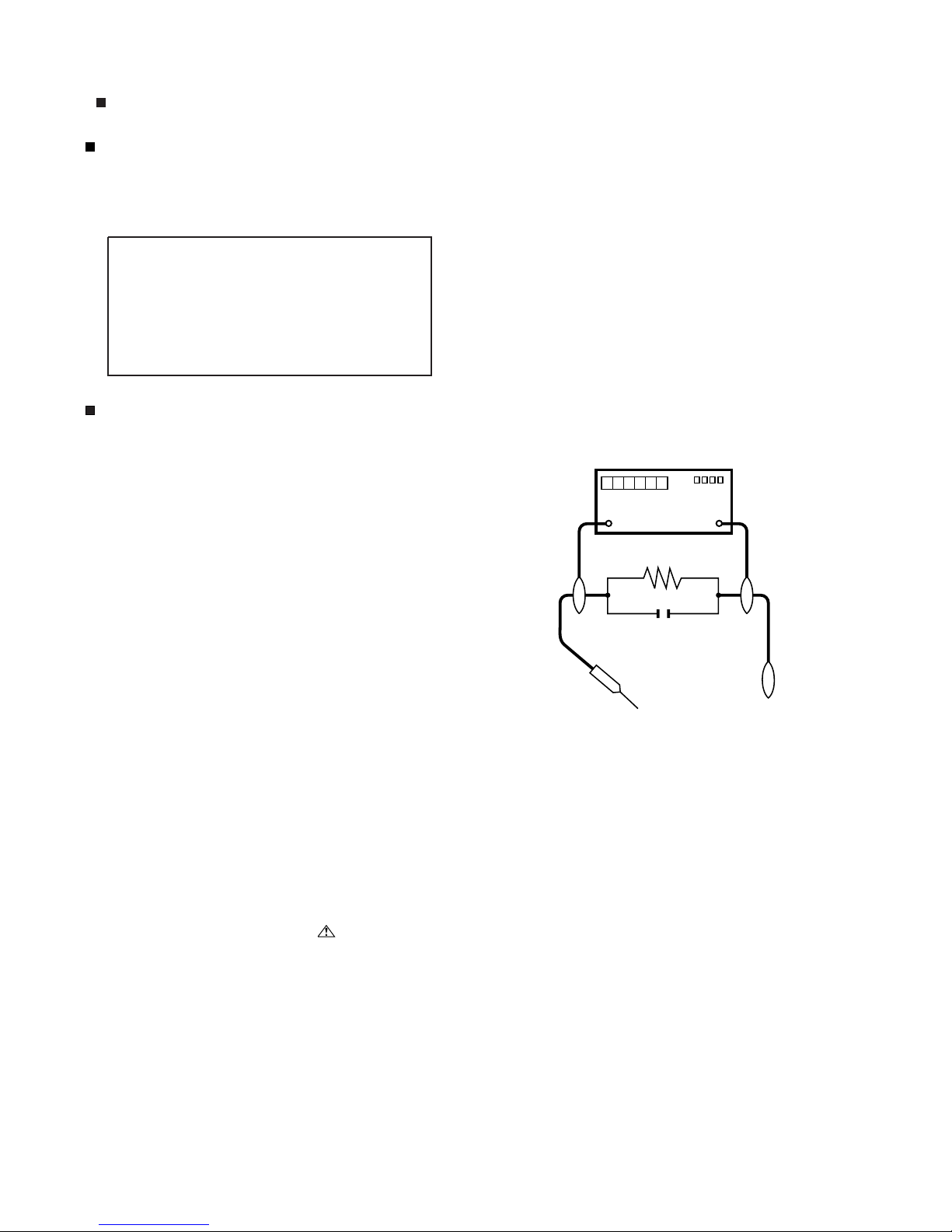
S'assurer qu'il n'y ait pas de danger d'électrocution en vérifiant la
fuite de courant, de la facon suivante:
Brancher le cordon d'alimentation directem-ent à une prise de courant de 120V. (Ne pas utiliser de transformateur d'isolation pour
cet essai).
A l'aide de deux fils à pinces, brancher une résistance de 1.5 kΩ
10 watts en parallèle avec un condensateur de 0.15µF en série
avec toutes les pièces métalliques exposées du coffret et une terre
connue comme une conduite électrique ou une prise de terre
branchée à la terre.
Utiliser un voltmètre CA d'une sensibilité d'au moins 5000Ω/V pour
mesurer la chute de tension en travers de la résistance.
Toucher avec la sonde d'essai les pièces métalliques exposées qui
présentent une voie de retour au châssis (antenne, coffret métallique, tête des vis, arbres de commande et des boutons, écusson,
etc.) et mesurer la chute de tension CA en-travers de la résistance.
Toutes les vérifications doivent être refaites après avoir inversé la
fiche du cordon d'alimentation. (Si nécessaire, une prise
d'adpatation non polarisée peut être utilisée dans le but de terminer ces vérifications.)
La tension de pointe mesurèe ne doit pas dépasser 0.75V (correspondante au courant CA de pointe de 0.5mA).
Dans le cas contraire, il y a une possibilité de choc électrique qui
doit être supprimée avant de rendre le récepteur au client.
PRECAUTION: POUR LA PROTECTION CONTINUE CONTRE LES RISQUES D'INCENDIE,
REMPLACER LE FUSIBLE
F701 (250V 8A), F702 (250V 1A)
F4702 (250V 4A),
F4701/F4703 (250V 3A ~ 127
O
C)
VERIFICATIONS CONTRE L'INCEN-DIE ET LE
CHOC ELECTRIQUE
Avant de rendre le récepteur à l'utilisateur, effectuer les vérifications suivantes.
DVM
ECHELLE CA
1.5k ohm
10W
0.15
µ
F
SONDE D'ESSAI
AUX PIECES
METALLIQUES
EXPOSEES
BRANCHER A UNE
TERRE CONNUE
AVIS POUR LA SECURITE
LC-46D62U/LC-52D62U
iii
PRECAUTIONS FOR USING LEAD-FREE SOLDER
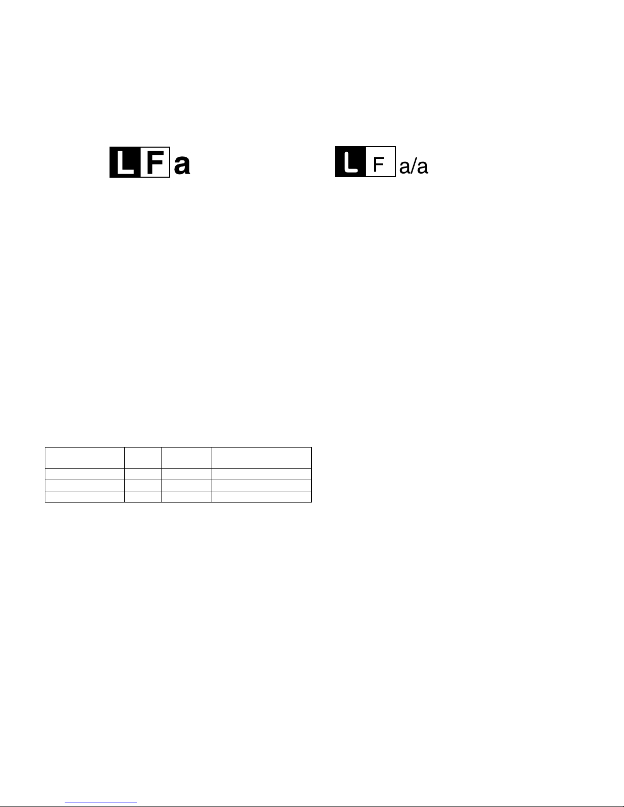
Employing lead-free solder
• “PWBs” of this model employs lead-free solder. The LF symbol indicates lead-free solder, and is attached on the PWBs and service manuals. The
alphabetical character following LF shows the type of lead-free solder.
Example:
Using lead-free wire solder
• When fixing the PWB soldered with the lead-free solder, apply lead-free wire solder. Repairing with conventional lead wire solder may cause damage or accident due to cracks.
As the melting point of lead-free solder (Sn-Ag-Cu) is higher than the lead wire solder by 40 °C, we recommend you to use a dedicated soldering
bit, if you are not familiar with how to obtain lead-free wire solder or soldering bit, contact our service station or service branch in your area.
Soldering
• As the melting point of lead-free solder (Sn-Ag-Cu) is about 220 °C which is higher than the conventional lead solder by 40 °C, and as it has poor
solder wettability, you may be apt to keep the soldering bit in contact with the PWB for extended period of time. However, Since the land may be
peeled off or the maximum heat-resistance temperature of parts may be exceeded, remove the bit from the PWB as soon as you confirm the
steady soldering condition.
Lead-free solder contains more tin, and the end of the soldering bit may be easily corroded. Make sure to turn on and off the power of the bit as
required.
If a different type of solder stays on the tip of the soldering bit, it is alloyed with lead-free solder. Clean the bit after every use of it.
When the tip of the soldering bit is blackened during use, file it with steel wool or fine sandpaper.
• Be careful when replacing parts with polarity indication on the PWB silk.
Lead-free wire solder for servicing
Indicates lead-free solder of tin, silver and copper. Indicates lead-free solder of tin, silver and copper.
PARTS CODE
PRICE
RANK
PART
DELIVERY
DESCRIPTION
ZHNDAi123250E BL J φ0.3mm 250g (1roll)
ZHNDAi126500E BK J φ0.6mm 500g (1roll)
ZHNDAi12801KE BM J φ1.0mm 1kg (1roll)
LC-46D62U/LC-52D62U
1 – 1
LC-46D62U
Service Manual
CHAPTER 1. SPECIFICATIONS
[1] SPECIFICATIONS
Digital cable
*
1
(64/256 QAM)
1-135ch (non-scrambled channel only)
*
1
Emergency alert messages via Cable are unreceivable.
• As part of policy of continuous improvement, SHARP reserves the right to make design and specification changes for product
improvement without prior notice. The performance specification figures indicated are nominal values of production units.
There may be some deviations from these values in individual units.
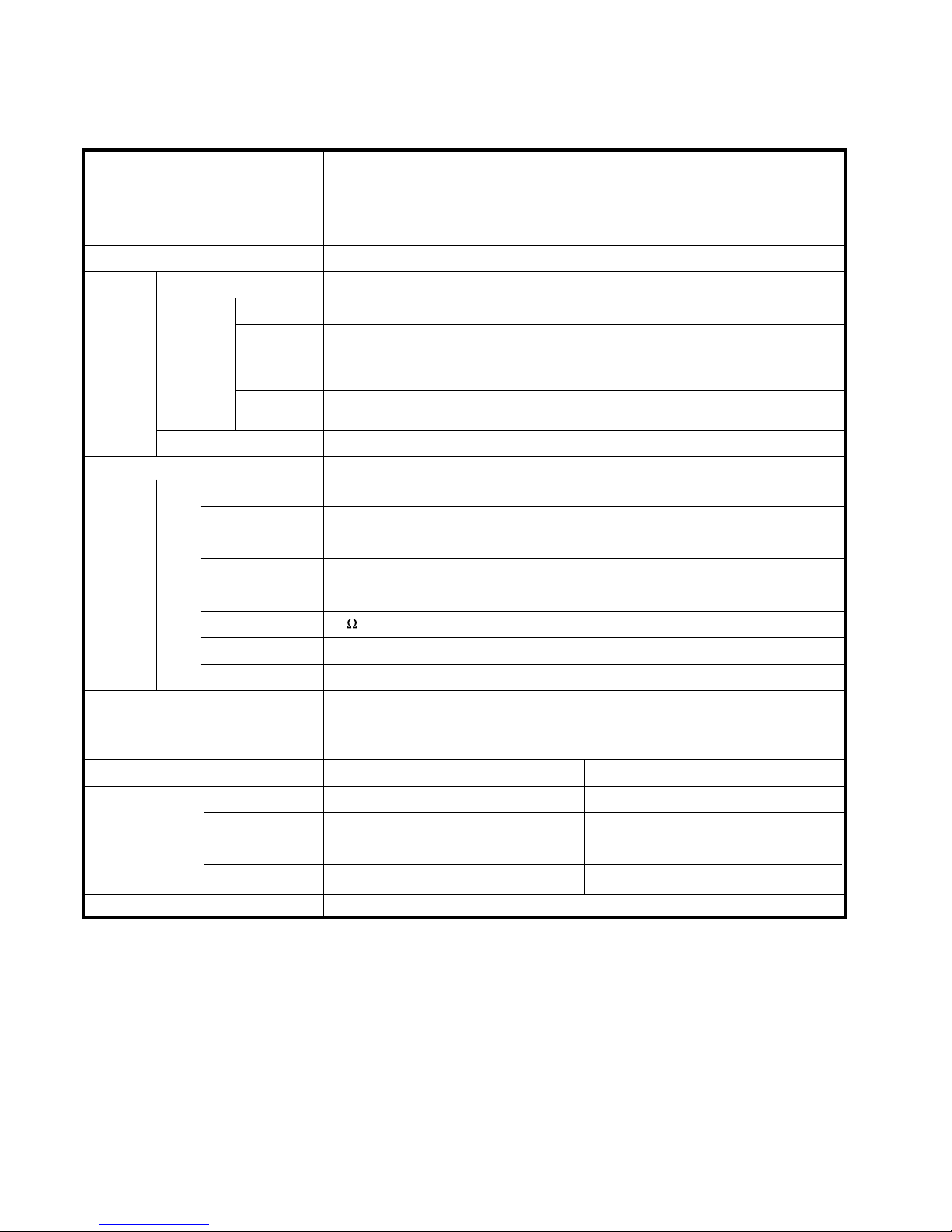
LCD panel
Number of dots
TV
Function
TV-standard (CCIR)
Receiving
Channel
VHF/UHF
CATV
Digital Terrestrial
Broadcast (8VSB)
Audio multiplex
Audio out
Terminals
Rear
INPUT 1
INPUT 2
INPUT 3
INPUT 4
INPUT 5
ANTENNA
DIGITAL AUDIO OUTPUT
OUTPUT
OSD language
Power Requirement
Power Consumption
Weight (approx.)
Dimension*
2
(WxHxD)
Operating temperature
6,220,800 dots (1920x1080x3 dots)
American TV Standard ATSC/NTSC System
VHF 2-13ch, UHF 14-69ch
1-135ch (non-scrambled channel only)
2-69ch
BTSC System
15Wx2
AV in, COMPONENT in
AV in, COMPONENT in
S-VIDEO in, AV in
Audio in, HDMI in with HDCP
HDMI in with HDCP
75 Unbalance, F Type x 1 for Analog (VHF/UHF/CATV) and Digital (AIR/CABLE)
Optical Digital audio output x 1 (PCM/Dolby Digital)
Audio out
English/French/Spanish
AC 120 V, 60 Hz (FOR NORTH AMERICA)
AC 110-240 V, 50/60 Hz (FOR OTHERS)
+32°F to +104°F (0°C to +40°C)
Item
Model: LC-46D62U Model: LC-52D62U
46" Advanced Super View & BLACK TFT
LCD
52" Advanced Super View & BLACK TFT
LCD
with stand
w/o stand
w/o stand
with stand
270 W (0.7 W Standby with AC 120V) 302 W (0.7 W Standby with AC 120V)
72.8 lbs./33.0 kg
81.6 lbs./37.0 kg
44
3
/8x317/64x1211/64inch
83.8 lbs./38.0 kg
92.6 lbs./42.0 kg
49
47
/64x3125/32x459/64inch
49
47
/64x347/32x1211/64inch
44
3
/8x2843/64x457/64inch
LC-46D62U/LC-52D62U
2 – 1
LC-46D62U
Service Manual
CHAPTER 2. OPERATION MANUAL
[1] OPERATION MANUAL
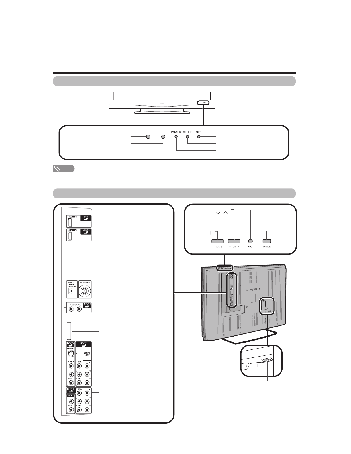
Part names
POWER button
TV (Front)
Channel buttons
(CH /)
Volume
buttons
(VOL /)
INPUT button
OPC indicator*
POWER indicator**
OPC sensor*
Remote control sensor
NOTE
*OPC: Optical Picture Control
**See page 15 for TV status indicator.
SLEEP indicator**
TV (Rear)
HDMI terminal (INPUT 4)
INPUT 3 terminals
AUDIO OUTPUT terminals
HDMI terminal (INPUT 5)
DIGITAL AUDIO OUTPUT terminal
Antenna/Cable in
INPUT 1 terminals
AC INPUT terminal
AUDIO terminal (INPUT 4)
INPUT 2 terminals
LC-46D62U/LC-52D62U
2 – 2
3
2
114
5
6
4
8
17
15
16
18
19
7
20
10
9
21
11 23
24
25
12
13 27
22
26
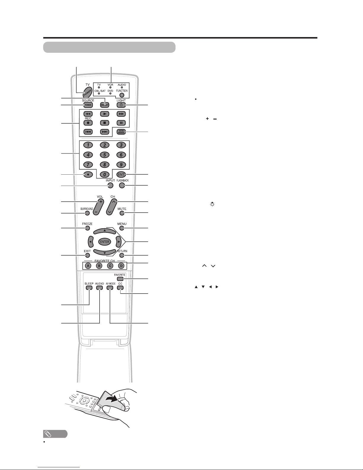
Part names
1 TV POWER: Switch the TV power on or enters standby
mode.
2 DISPLAY: Display the channel information.
3 SOURCE POWER: Turns the power of the external
equipment on and off.
4 External equipment operational buttons: Operate the
external equipment.
50…9:Set the channel.
6(DOT):
7 INPUT: Select a TV input source. (TV, INPUT 1, INPUT 2,
INPUT3,INPUT4,INPUT5)
8VOL/:Set the volume.
9 SURROUND: Select Surround settings.
10 FREEZE: Set the still image. Press again to return to
normal screen.
11 EXIT: Turn off the menu screen.
12 SLEEP: Set the sleep timer.
13 AUDIO: Selects the MTS/SAP or the audio mode during
multi-channel audio broadcasts.
14 FUNCTION: Switches the remote control for TV, CBL/
SAT, VCR, DVD and AUDIO operation. Indicator lights up
for the current mode.
* To enter the code registration mode, you need to press
FUNCTION and DISPLAY at the same time.
15 LIGHT : When pressed all buttons on the remote
control unit will light. The lighting will turn off if no
operations are performed within about 5 seconds. This
button is used for performing operations in low-light
situations.
16 VIEW MODE: Select the screen size.
17 ENT: Jumps to a channel after selecting with the 0…9
buttons.
18 FLASHBACK:Return to the previous channel or external
input mode.
19
CH / : Select the channel.
20 MUTE: Mute the sound.
21 MENU: Display the menu screen.
22 ////ENTER: Select a desired item on the
screen.
23 RETURN: Return to the previous menu screen.
24 FAVORITE CH
A, B, C, D: Select 4 preset favorite channels in 4 different
categories.
While watching, you can toggle the selected channels by
pressing A, B, C and D.
25 FAVORITE: Register favorite channel.
26 CC: Display captions from a closed-caption source.
27 AV MODE: Select an audio or video setting. (When the
input source is TV, INPUT 1, 2 or 3: STANDARD, MOVIE,
GAME, USER, DYNAMIC (Fixed), DYNAMIC. When
the input source is INPUT 4 or 5: STANDARD, MOVIE,
GAME, PC, USER, DYNAMIC (Fixed), DYNAMIC)
Remote control unit
NOTE
When using the remote control unit, point it at the TV.
LC-46D62U/LC-52D62U
2 – 3
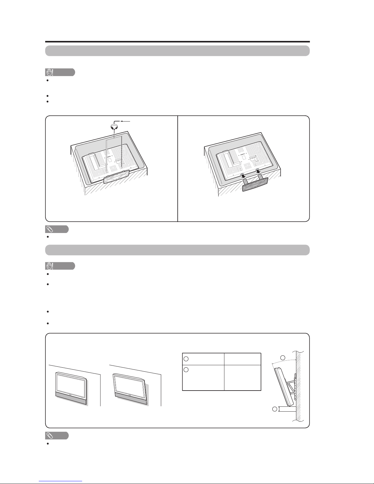
Removing the stand
Before detaching (or attaching) stand, unplug the AC cord from the AC INPUT terminal.
CAUTION
Do not remove the stand from the TV unless using an optional wall mount bracket to mount it.
Before attaching/detaching stand
Before performing work make sure to turn off the TV.
Before performing work spread cushioning over the base area to lay the TV on. This will prevent it from being
damaged.
Setting the TV on the wall
CAUTION
This TV should be mounted on the wall only with the AN-52AG1 (SHARP) wall mount bracket. The use of other
wall mount brackets may result in an unstable installation and may cause serious injuries.
Installing the TV requires special skill that should only be performed by qualified service personnel. Customers
should not attempt to do the work themselves. SHARP bears no responsibility for improper mounting or
mounting that results in accident or injury.
Using an optional bracket to mount the TV
You can ask a qualified service professional about using an optional AN-52AG1 bracket to mount the TV to the
wall.
Carefully read the instructions that come with the bracket before beginning work.
Hanging on the wall
AN-52AG1 wall mount bracket.
(See the bracket instructions for details.)
Vertical mounting
About setting the TV angle and height adjustment
Unfasten the four screws used to secure the stand in
place.
Detach the stand from the TV.
(Hold the stand so it will not drop from the edge of the
base area.)
Appendix
NOTE
To attach the stand, perform the above steps in reverse order.
Angular mounting
1
5/0/ 5 cm
(canbemoved
5cmupor
down)
0/5/10/15/20°
NOTE
Detach the cable clamps on the rear of the TV when using the optional mount bracket.
1
Angle of TV
2
Height
Adjustment
2
1
2
-
+
Hex key
LC-46D62U/LC-52D62U
2 – 4
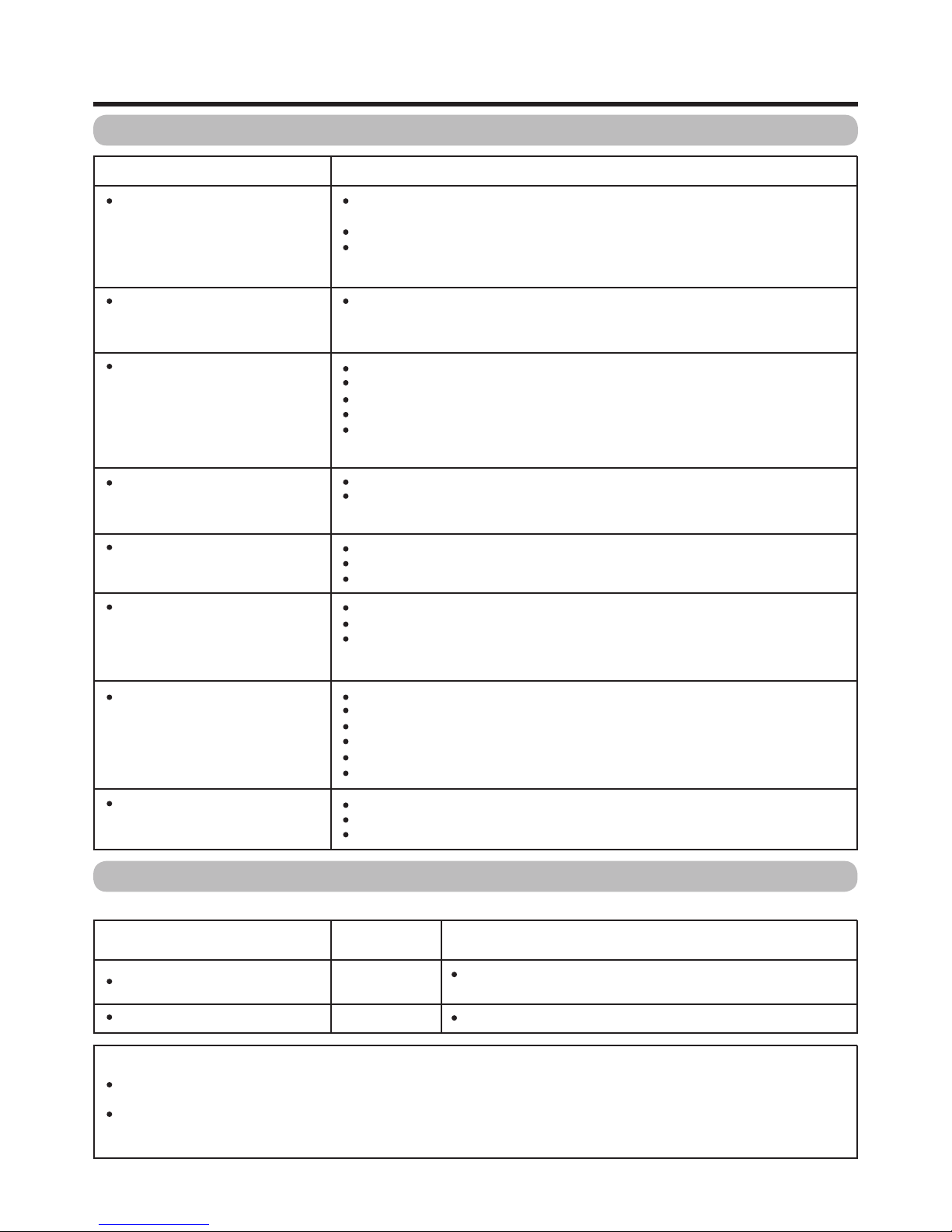
Troubleshooting
Possible Solution
Is the volume too low?
Is "Variable" selected in "Output Select"?
Haveyou pressed MUTE on the remote control unit?
Cautions regarding use in high and low temperature environments
Appendix
Problem
No power
Unit cannot be operated.
Remote control unit does not
operate.
Picture is cut off/with sidebar
screen.
Strange color, light color, or color
misalignment
Power is suddenly turned off.
No picture
No sound
Check if you pressedTV POWER on the remote control unit. If the
indicator on the TV does not light up, press POWER on the TV.
IstheACcorddisconnected?
Has the power been turned on?
External influences such as lightning, static electricity, may cause improper
operation. In this case, operate the unit after first turning on the power of the TV or
unplugging the AC cord and replugging it in after 1 or 2 minutes.
Is the FUNCTION set correctly? Set it to the TV setting position.
Are batteries inserted with polarity (+,-) aligned?
Are batteries worn out? (Replace with new batteries.)
Are you using it under strong or ”uorescent lighting?
Is a fluorescent light illuminated near the remote control sensor?
Is the image position correct?
Are screen mode adjustments such as picture size made correctly?
Adjust the picture tone.
Is the room too bright? The picture may look dark in a room that is too bright.
Check the input signal setting.
Is the sleep timer set?
Check the power control settings.
The unit's internal temperature has increased. Remove any objects blocking vent
or clean.
Is connection to other components correct?
Is correct input signal source selected after connection?
Is the correct input selected?
Is picture adjustment correct?
Is "On" selected in "Audio Only"?
Is a non-compatible signal being input?
When the unit is used in a low temperature space (e.g. room, office), the picture may leave trails or appear slightly delayed..
This is not a malfunction, and the unit will recover when the temperature returns to normal.
Do not leave the unit in a hot or cold location. Also, do not leave the unit in a location exposed to direct sunlight or near a
heater, as this may cause the cabinet to deform and the Liquid Crystal panel to malfunction.
Storage temperature: -4°F to +140°F (-20°C to +60°C)
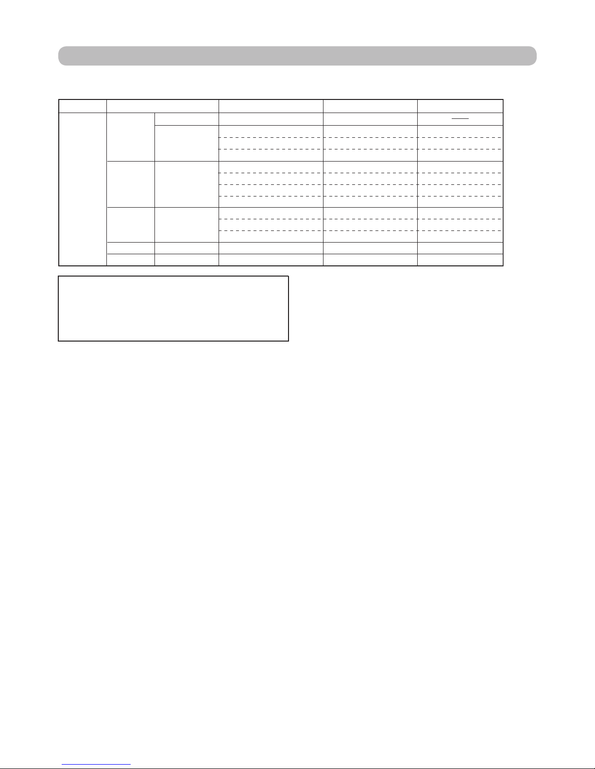
Troubleshooting-Digital broadcasting
The error message about reception of broadcast
Failed to receive broadcast.
E203 Check the broadcast time in the program guide.
The example of an error
message displayed on a screen
No broadcast now.
Error code
E202
Possible Solution
Check the antenna cable. Check that the antenna is correctly
setup.
LC-46D62U/LC-52D62U
2 – 5
PC format compatibility chart
DDC is a registered trademark of Video Electronics
Standards Association.
Power Management is a registered trademark of Sun
Microsystems, Inc.
VGA and XGA are registered trademarks of International
Business Machines Co., Inc.
PC
31.5 kHz
31.5 kHz
37.9 kHz
37.5 kHz
35.1 kHz
37.9 kHz
48.1 kHz
46.9 kHz
48.4 kHz
56.5 kHz
60.0 kHz
47.7 kHz
64.0 kHz
640x480
720x400
VGA
800x600SVGA
XGA 1024 x 768
WXGA 1360 x 768
SXGA 1280 x 1024
70 Hz
60 Hz
72 Hz
75 Hz
56 Hz
60 Hz
72 Hz
75 Hz
60 Hz
70 Hz
75 Hz
60 Hz
60 Hz
O
O
O
O
O
O
O
O
O
O
O
O
PC Horizontal Frequency VESA StandardResolution Vertical Frequency
It is necessary to set the PC format correctly to display XGA and WXGA signal. Refer to OPERATION MANUAL
to set PC input signals.
LC-46D62U/LC-52D62U
2 – 6
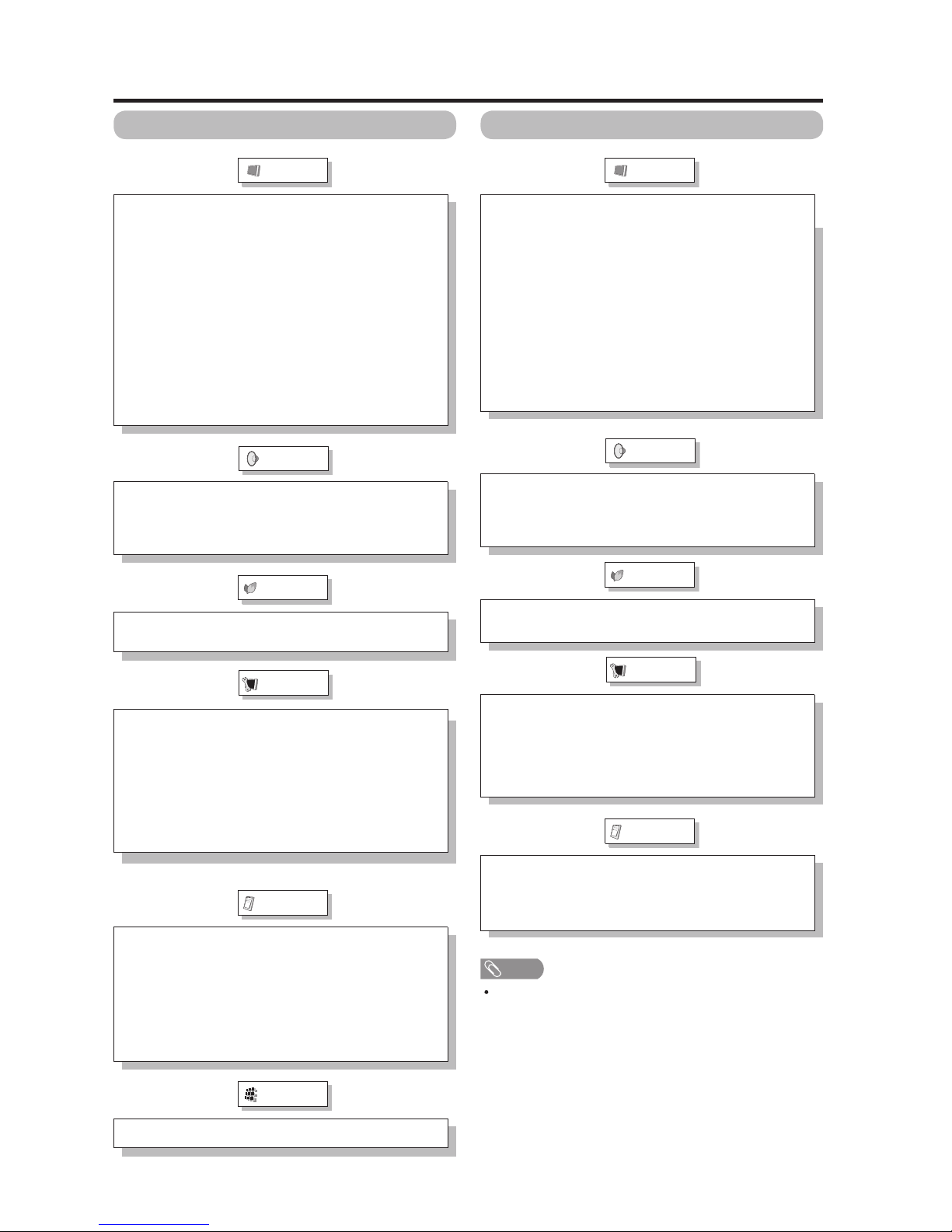
Picture
Audio
Option
Power Control
Digital Setup
Picture
Audio
Option
Power Control
Menu items for TV/INPUT 1/2/3
OPC
Backlight
Contrast
Brightness
Color
Tint
Sharpness
Advanced
Color Temp.
Black
Fine Motion
3D-Y/C
Monochrome
Film Mode
Range of OPC
EZ Setup
CH Setup
Antenna Setup-DIGITAL
Input Skip
Input Label
Parental CTRL
Position
Language
Reset
Treble
Bass
Balance
Surround
Audio Only
Digital Noise Reduction
Input Select
Output Select
Color System
Caption Setup
Program Title Display
Favorite CH
No Signal Off
No Operation Off
Audio Setup
Menu items for HDMI (INPUT 4/5)
OPC
Backlight
Contrast
Brightness
Color
Tint
Sharpness
Advanced
Color Temp.
Black
Fine Motion
Monochrome
Film Mode
Range of OPC
Input Skip
Input Signal
Input Label
Position
Language
Reset
Treble
Bass
Balance
Surround
Audio Only
Digital Noise Reduction
HDMI Setup
Output Select
No Signal Off
No Operation Off
NOTE
Some menu items may not be displayed depending on the
selected input source.
Basic adjustment settings
Setup
Setup
LC-46D62U/LC-52D62U
3 – 1
LC-46D62U
Service Manual
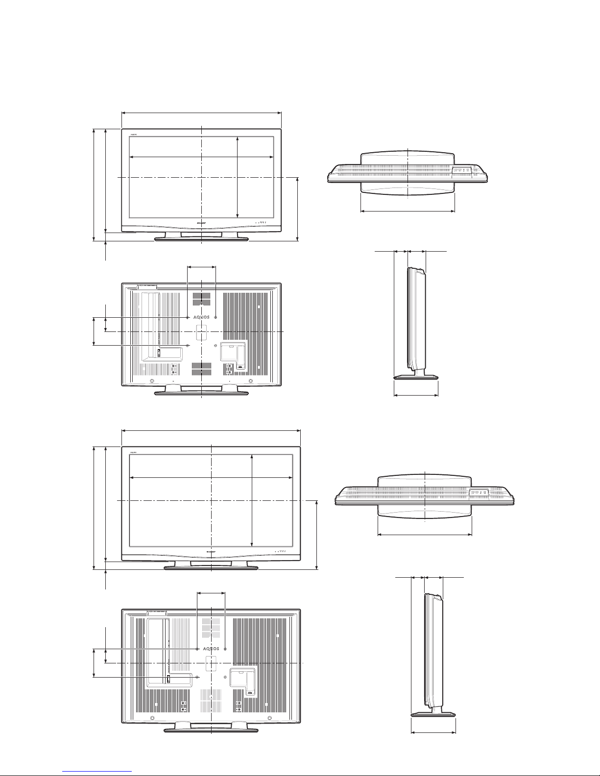
CHAPTER 3. DIMENSIONS
[1] DIMENSIONS
2563/64(660)
17
11
/
16
(449)
443/8(1127)
12
11
/64(309)
3
7
/8(98)
4
57
/64(124)
3
61
/
64
(100)
77/8(200)
7
7
/
8
(200)
28
43
/
64
(728)
31
7
/
64
(790)
2
29
/
64
(62)
407/32(1021.4)
22
21
/
32
(575.4)
2563/64(660)
12
11
/64(309)
49
47
/64(1263)
45
31
/64(1155.0)
25
41
/
64
(651.0)
19
1
/
4
(489)
325/32(96) 459/64(125)
3
61
/
64
(100)
31
25
/
32
(807)
34
7
/
32
(869)
77/8(200)
7
7
/
8
(200)
2
29
/
64
(62)
Unit: inch/(mm)
LC-46D62U
LC-52D62U
LC-46D62U/LC-52D62U
4 – 1
LC-46D62U
Service Manual
CHAPTER 4. REMOVING OF MAJOR PARTS
[1] REMOVING OF MAJOR PARTS (LC-46D62U)
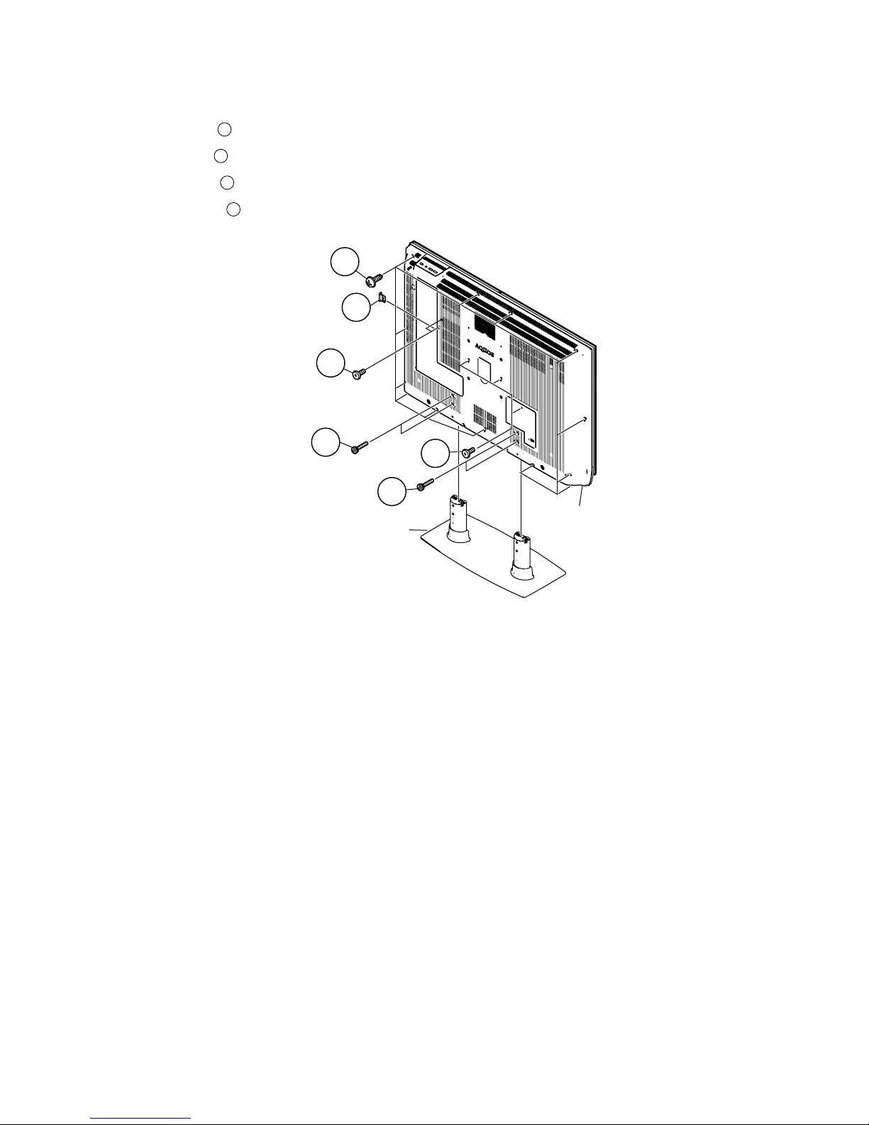
1. Detach the SD Card Cover .
2. Remove the 4 lock screws and detach the Stand.
3. Remove the 5 lock screws .
4. Remove the 13 lock screws and detach the Rear Cabinet.
1
2
3
4
3
2
2
3
1
4
SD Card Cover
Rear Cabinet
Stand

LC-46D62U/LC-52D62U
4 – 2
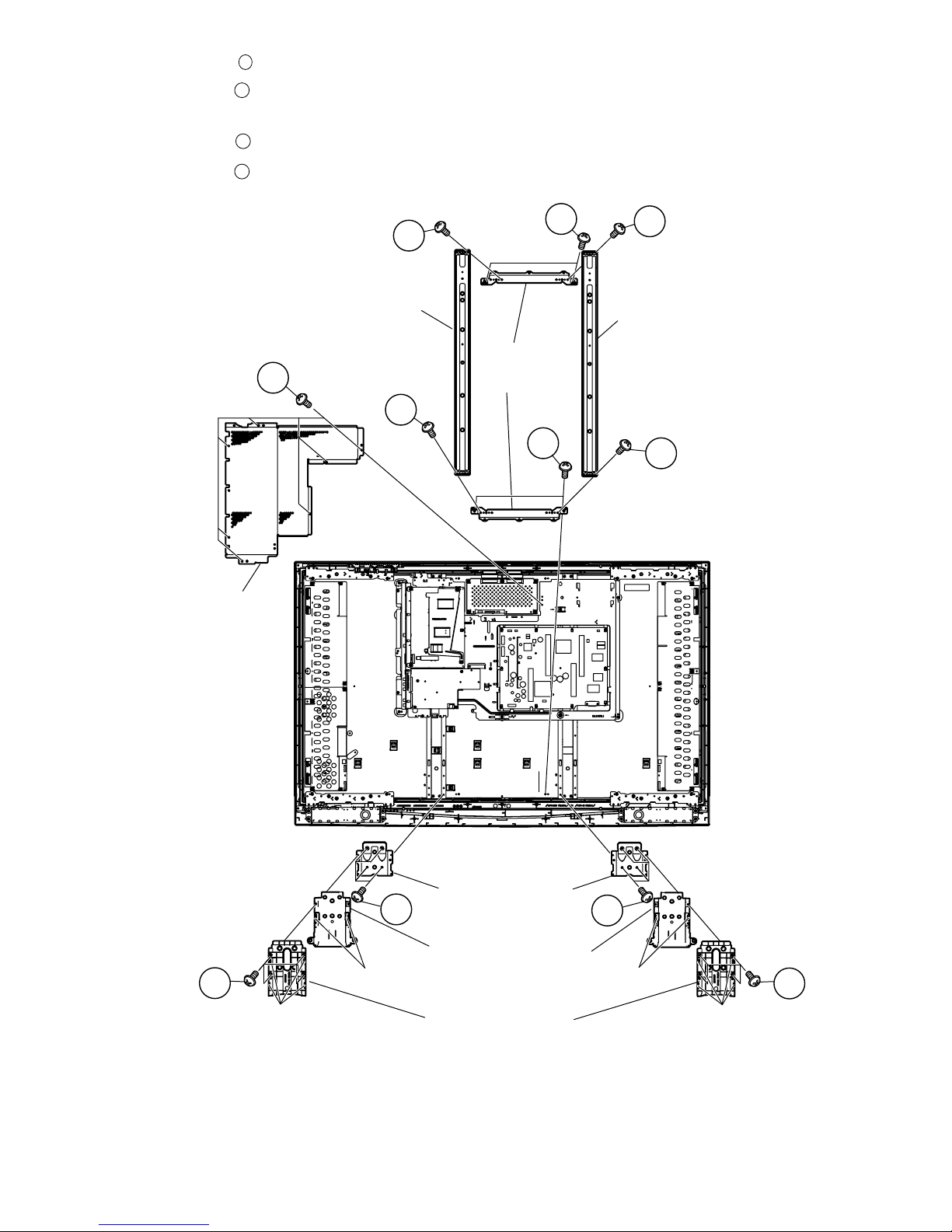
5. Remove the 8 lock screws and detach the Brige Angle and Chassis Fix Angle.
6. Remove the 8 lock screws 8 lock point and detach the Stand St Cover-R
7. Remove the 4 hook and detach the Stand assist Holder.
8. Remove the 8 lock screws and detach the Stand Fix Angle.
9. Remove the 7 lock screws and detach the Main Shield.
5
6
7
8
5
5
5
5
5
5
8
6
7
7
6
Lock point
Stand St Cover-R
Stand Fix Angle
Stand Assist Holder
Chassis
Fix Angle
Brige Angle
Brige Angle
Hook
Lock point
Hook
Main Shield

LC-46D62U/LC-52D62U
4 – 3
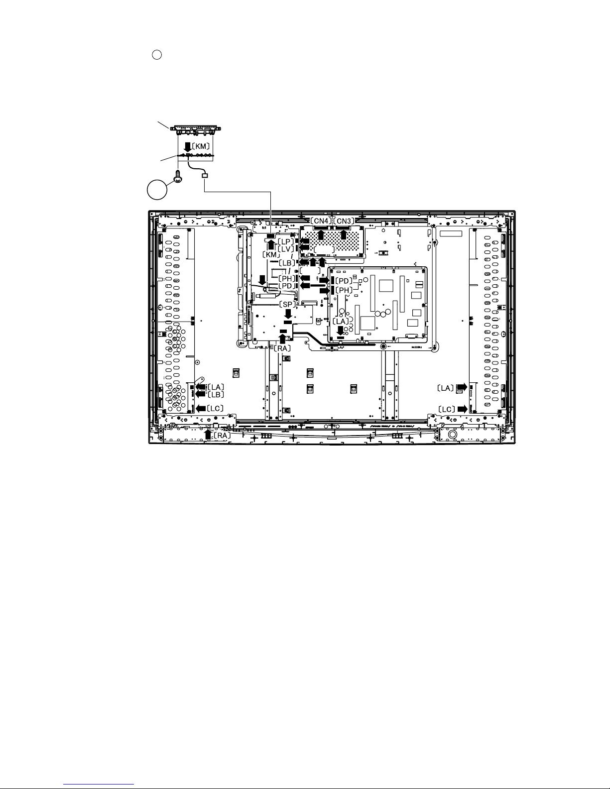
10.Disconnect all the connectors from all the PWBs.
11.Remove the 2 lock screws and detach the KEY PWB.
10
LP
LV
10
KEY PWB
Top Cover
LC-46D62U/LC-52D62U
4 – 4
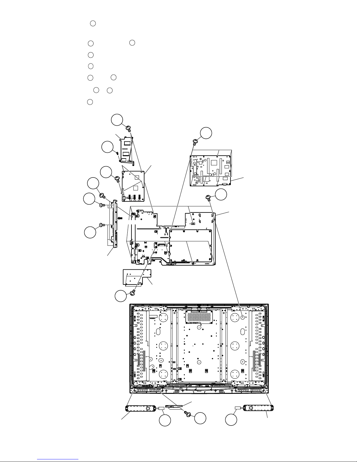
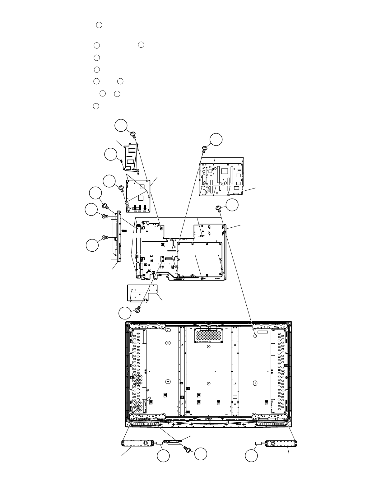
12.Remove the 7 lock screws and detach the Tray Chassis.
13.Disconnect the 3 connectors (MA, FC, SA) , and COAXIAL Wire.
14.Remove the 2 lock screws , 3 lock screws and detach the Terminal Angle.
15.Remove the 7 lock screws and detach the POWER SUPPLY Unit.
16.Remove the 4 lock screws and detach the TERMINAL PWB.
17.Remove the 5 lock screws , rivet and detach the Heat Sink and MAIN PWB.
18.Disconnect the 2 connectors , and detach the Speaker-L and R.
19.Remove the 2 lock screws and detach the R/C, LED PWB.
11
12
13
14
15
16
17
18
19
20
Tray Chassis
POWER
SUPPLY PWB
MAIN PWB
Heat Sink
TERMINAL PWB
Terminal Angle
Speaker-R
Speaker-L
R/C, LED PWB
16
17
16
11
12
13
14
11
15
20
18
19
MA FC SA
COAXIAL Wire
LC-46D62U/LC-52D62U
4 – 5
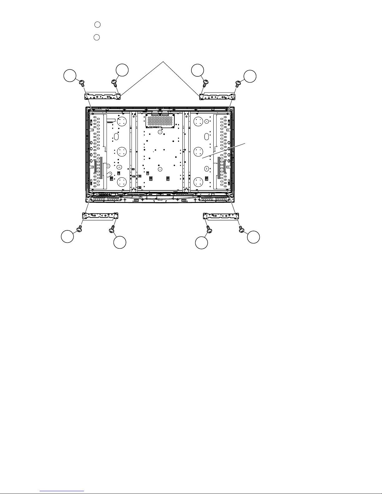
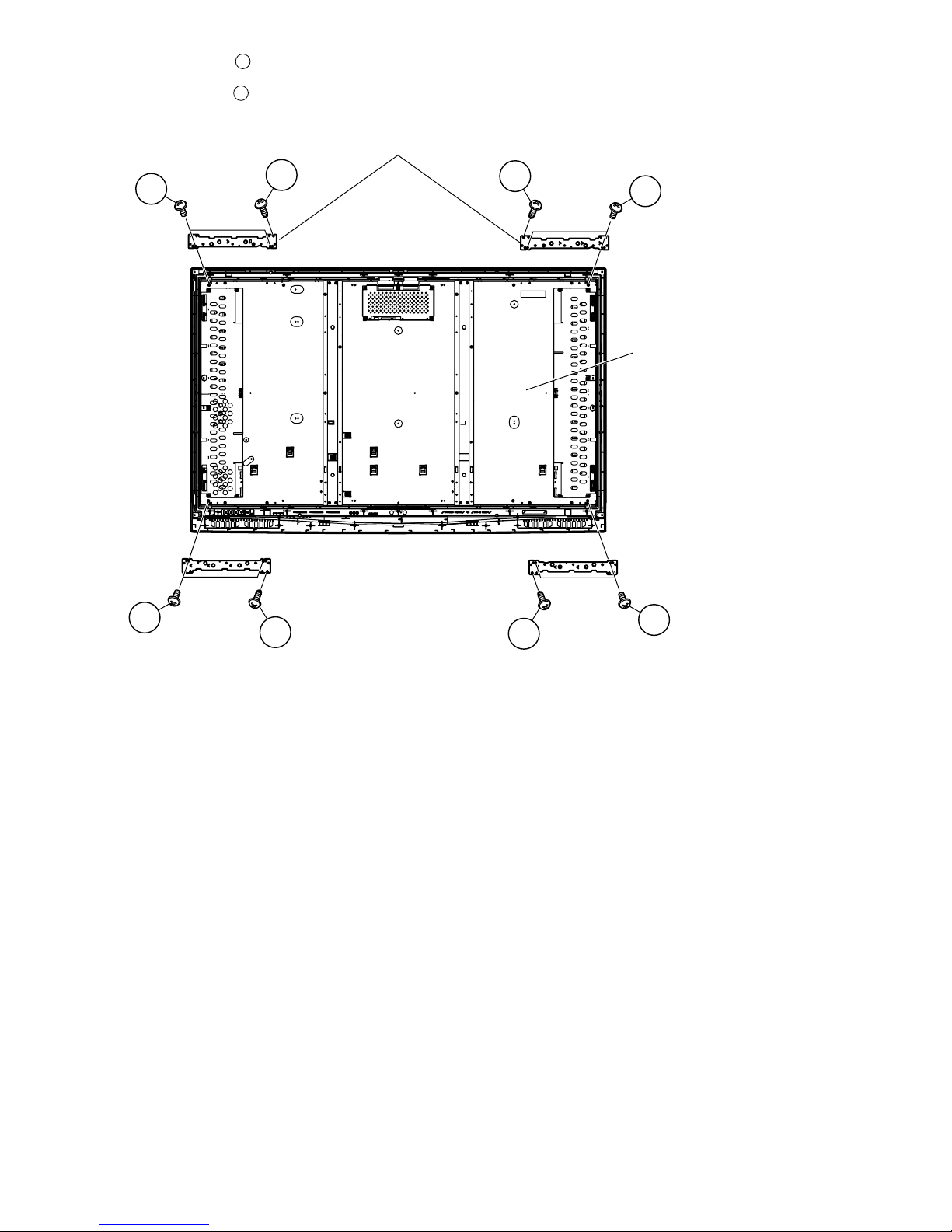
20.Remove the 4 lock screws and detach the LCD Panel Module.
21.Remove the 8 lock screws and detach the Chassis Fix Angle T/B.
21
22
22
21
21
22
22
21
21
22
Chassis Fix Angle T/B
LCD Panel Module
LC-46D62U/LC-52D62U
4 – 6
[2] REMOVING OF MAJOR PARTS (LC-52D62U)
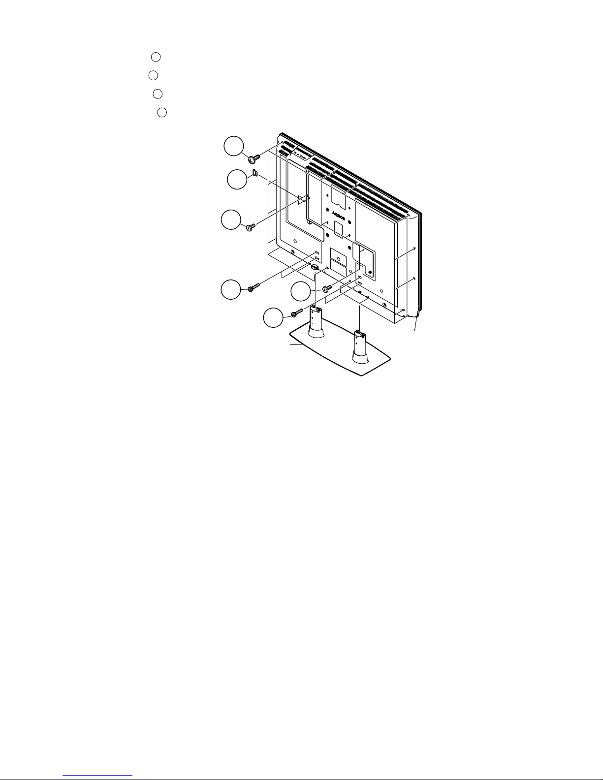
1. Detach the SD Card Cover .
2. Remove the 4 lock screws and detach the Stand.
3. Remove the 5 lock screws .
4. Remove the 18 lock screws and detach the Rear Cabinet.
1
2
3
4
4
Rear Cabinet
Stand
1
SD Card Cover
3
3
2
2
LC-46D62U/LC-52D62U
4 – 7
5. Remove the 8 lock screws and detach the Brige Angle and Chassis Fix Angle.
6. Remove the 8 lock screws 8 lock point and detach the Stand St Cover-R
7. Remove the 4 hook and detach the Stand assist Holder.
8. Remove the 8 lock screws and detach the Stand Fix Angle.
9. Remove the 7 lock screws and detach the Main Shield.
5
6
7
8
Brige Angle
Main Shield
Brige Angle
5
5
5
5
5
7
6
7
6
5
8
Chassis
Fix Angle
Stand St Cover-R
Stand Assist Holder
Stand Fix Angle
Lock point
Lock point
Hook
Hook
LC-46D62U/LC-52D62U
4 – 8
10.Disconnect all the connectors from all the PWBs.
11.Remove the 2 lock screws and detach the KEY PWB.
10
KEY PWB
Top Cover
10
LV
LP
LC-46D62U/LC-52D62U
4 – 9
12.Remove the 7 lock screws and detach the Tray Chassis.
13.Disconnect the 3 connectors (MA, FC, SA) , and COAXIAL Wire.
14.Remove the 2 lock screws , 3 lock screws and detach the Terminal Angle.
15.Remove the 7 lock screws and detach the POWER SUPPLY Unit.
16.Remove the 4 lock screws and detach the TERMINAL PWB.
17.Remove the 5 lock screws , rivet and detach the Heat Sink and MAIN PWB.
18.Disconnect the 2 connectors , and detach the Speaker-L and R.
19.Remove the 2 lock screws and detach the R/C, LED PWB.
11
12
13
14
15
16 17
18
19
20
MAIN PWB
Heat Sink
Tray Chassis
POWER
SUPPLY PWB
TERMINAL PWB
Terminal Angle
Speaker-R
Speaker-L
R/C, LED PWB
16
17
16
11
12
13
15
11
14
20
18
19
COAXIAL Wire
MA FC SA
LC-46D62U/LC-52D62U
4 – 10
20.Remove the 4 lock screws and detach the LCD Panel Module.
21.Remove the 8 lock screws and detach the Chassis Fix Angle T/B.
21
22
Chassis Fix Angle T/B
21
22
21
22
22
21
21
22
LCD Panel Module
LC-46D62U/LC-52D62U
5 – 1
LC-46D62U
Service Manual
CHAPTER 5. ADJUSTMENT
[1] ADJUSTMENT PROCEDURE
The adjustment values are set to the optimum conditions at the factory before shipping. If a value should become improper or an adjustment is
required due to part replacement, make an adjustment according to the following procedure.
1. After replacement of any PWB unit and/or IC for repair, please note the following.
When replacing the following units, make sure to prepare the new units loaded with updated software.
MAIN Unit: DUNTKD934FM01 (LC-46D62U) / DUNTKD934FM02 (LC-52D62U)
2. Upgrading of each microprocessor software
CAUTION: Never “POWER OFF” the unit when software upgrade is ongoing.
Otherwise the system may be damaged beyond recovery.
2.1. Software version upgrade
The model employs the following software.
•Main software
• Monitor microprocessor software
The main software and the monitor microprocessor software can be upgraded by using a general-purpose SD memory card.
The followings are the procedures for upgrading, explained separately for each of the main software, the monitor microprocessor software.
2.2. Main software version upgrade
2.2.1 Get ready before you start
• SD memory card of 32MB or higher capacity
• PC running on Windows 98/98SE/ME/2000/XP operating system
• SD memory card reader/writer with USB connectivity
• SD memory card formatting software
(Downloadable at http://panasonic.jp/support/audio/sd/download/sd_formatter_e.html)
2.2.2 Preparations
To upgrade the main software, it is necessary to get ready the SD card for version upgrade before you start. Follow the steps below and create the SD
card for version upgrade.
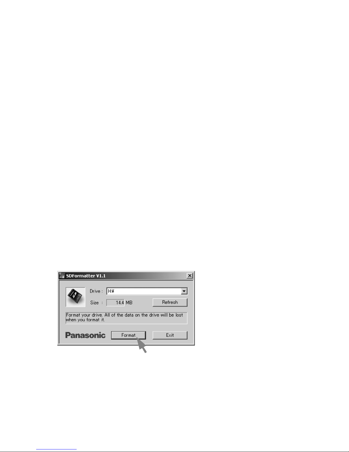
1. Insert the SD card into the SD card reader/writer. Start the SD card formatting software. Click [Format]. (When you have the drive options, select
the drive where the SD card is inserted before you proceed.)
LC-46D62U/LC-52D62U
5 – 2
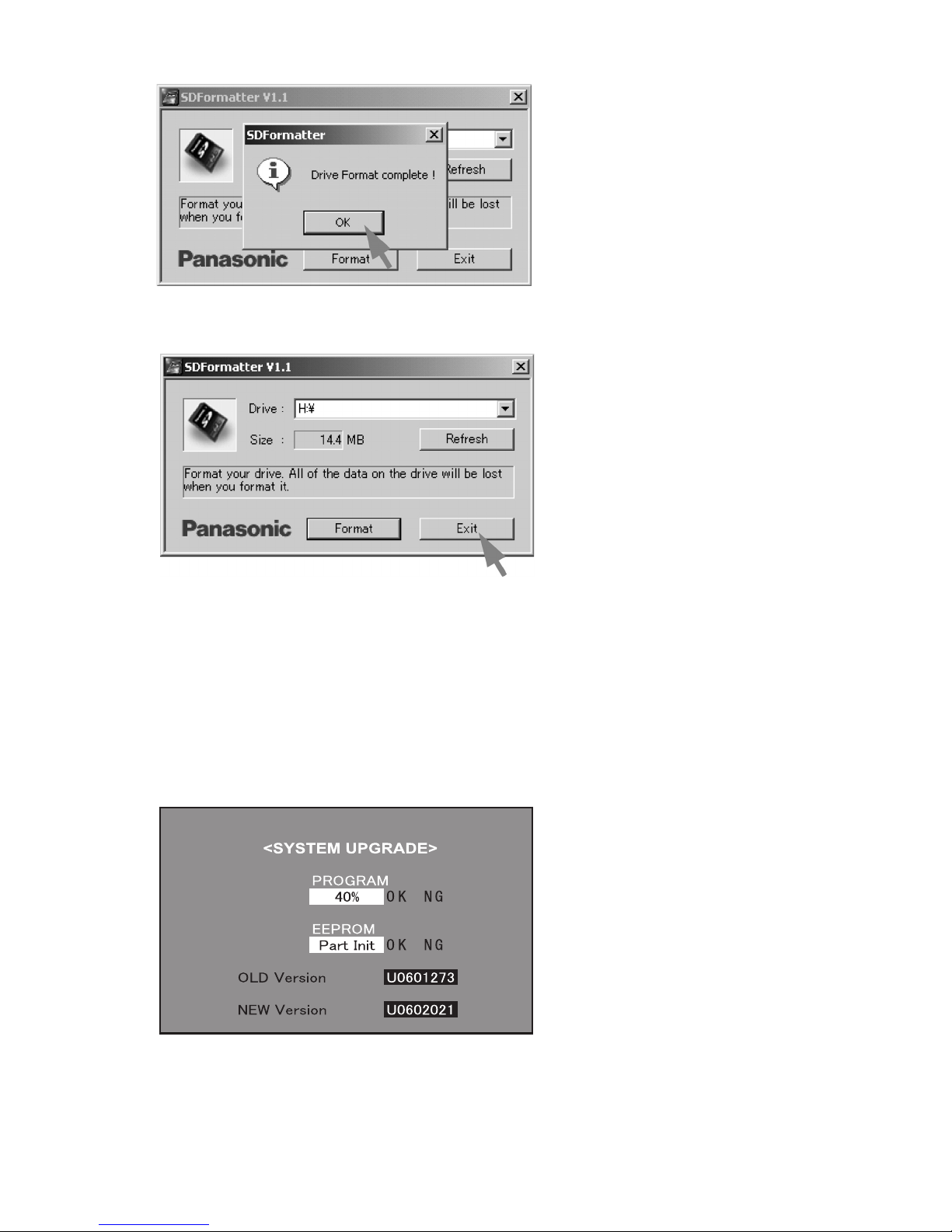
2. When the formatting is over, the following window appears. Click [OK].
3. Click [Exit] to finish the formatting.
NOTE: When you are done, take out the SD card once to make sure it is finished, and then insert it again.
4. Copy the binary image file DA60UAxx.SDC (named temporarily) for version upgrade to the root directory (folder) of the SD card drive.
NOTE: In the SD card drive, do not store other folders or unrelated files, or more than one binary image files for version upgrade.
Now the SD card for version upgrade is ready.
2.2.3 Upgrading the software
1. Turn off the AC power (Unplug the AC power cord).
2. Insert the upgrading SD card (prepared as instructed above) into the service slot.
NOTE: Be careful not to insert the SD card in the wrong way. Otherwise the card may come into the set and fail to come out.
3. Turn on the AC power (Plug in the AC power cord).
4. A couple to dozen seconds after the set starts, the upgrade screen below shows up.
LC-46D62U/LC-52D62U
5 – 3
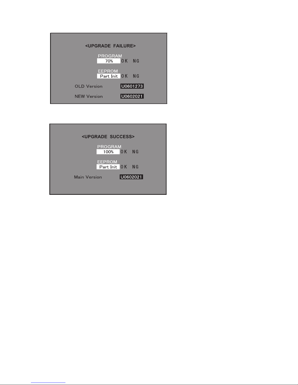
5. If any of the procedures fails, the following upgrade failure screen shows up. For the failing procedure, the “NG” marking turns red.
NOTE: In such case, try to upgrade the software again. If it still fails, the hardware may be in trouble.
6. When all the procedures are complete, the following upgrade success screen shows up. The new software version can be confirmed on screen.
The version number appears when each item has been successfully upgraded. Finally the main version number appears on screen.
7. Turn off the AC power (Unplug the AC power cord). Take out the upgrading SD card.
8. Now the software has been upgraded.
NOTE: Then get the set started and call the process adjustment screen 1/26 to check the main software version.
CAUTION: 1) Do not take out and put in the SD memory card during formatting.
2) With the SD formatted, all the data stored on the medium will be deleted.
3) Do not start the SD formatting with the memory card’s WRITE PROTECT switch still on.
4) If the SD memory card format software does not recognize the SD memory card, take out and put in the SD memory card again, and
click the “UPDATE” button.
5) After checking the performance, use the set under its interface environment.
6) The SD formatting is impossible on drives that are not recognized “REMOVABLE”.
2.3. Upgrading the monitor microprocessor software
2.3.1 Kit
Have the above “Upgrading the main software” kit or equivalent at hand.
2.3.2 Preparations
As discussed in “Upgrading the main software” earlier, create the SD card for upgrading the monitor microprocessor software. For this SD card, use
the monitor microprocessor upgrading binary image file.
2.3.3 Upgrading procedure
To follow the monitor microprocessor software upgrading, the monitor screen upgrade progress indicator and the flashing power LED indicator can be
used.
1. Turn off the AC power (Unplug the AC power cord).
2. Insert the upgrading SD card (prepared as instructed above) into the service slot at the back of the set. Insert the SD card with its logo-printed face
upward (visible). Be careful not to insert the SD card in the wrong way. Otherwise the card may come into the set and fail to come out.
3. Turn on the AC power (Plug in the AC power cord).
CAUTION: Now the monitor microprocessor software starts getting upgraded. Be very careful not to turn off the power while the software is being
upgraded. Otherwise the software will fail to upgrade itself and the set will fail to get started.
LC-46D62U/LC-52D62U
5 – 4
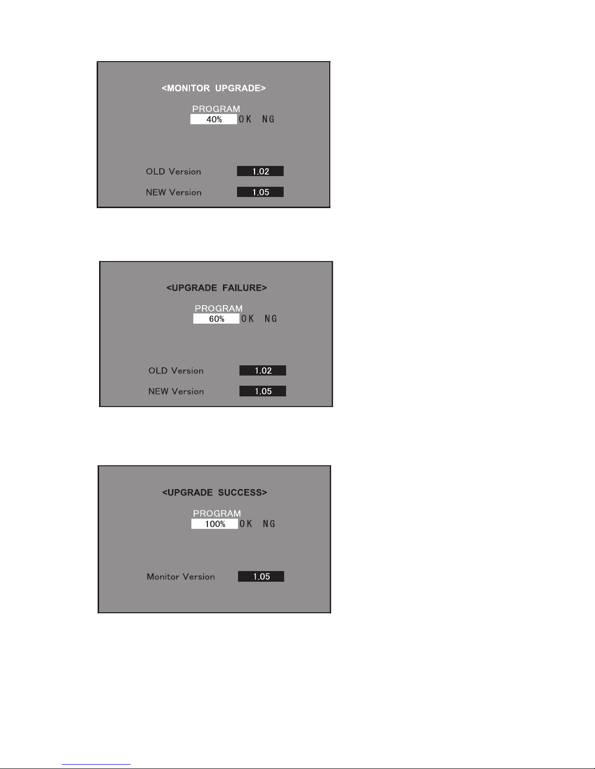
4. A couple to dozen seconds after the set starts, the upgrade screen below shows up. The upgrade progress is indicated on screen. The power LED
indicator goes out once and then starts flashing in blue. (It takes 2-3 minutes to get the monitor microprocessor software upgraded.)
5. If the procedure fails, the following upgrade failure screen shows up and the “NG” marking turns red. The power LED indicator fails to start flashing
in blue. Even if the usual screen reappears in several seconds, do the procedure from Step “1” again.
NOTE: In case of failure, try to upgrade the software again. If it still fails, the hardware may be in trouble.
6. When the procedure is complete, the following upgrade success screen shows up. The new software version can be confirmed on screen. The
upgrade success can also be confirmed when the power LED indicator and the OPC LED indicator start flashing alternately in blue and green,
respectively. Double-check the upgrading and turn off the AC power (Unplug the AC power cord). Take out the upgrading SD card. Now the software has been upgraded.
Finally get the set started and call the process adjustment screen 1/27 to check the monitor microprocessor software version.
LC-46D62U/LC-52D62U
5 – 5
3. Entering and exiting the adjustment process mode
1) Before entering the adjustment process mode, the AV position RESET in the video adjustment menu.
2) While holding down the “VOL (–)” and “INPUT” keys at a time, plug in the AC cord of the main unit to turn on the power.
The letter “<K>” appears on the screen.
3) Next, hold down the “VOL (–)” and “CH ( )” keys at a time.
(The “VOL (–)” and “CH ( )” keys should be pressed and held until the display appears.)
Multiple lines of blue characters appearing on the display indicate that the unit is now in the adjustment process mode.
When you fail to enter the adjustment process mode (the display is the same as normal startup), retry the procedure.
4) To exit the adjustment process mode after the adjustment is done, unplug the AC cord from the outlet to make a forced shutdown. (When the
power was turned off with the remote controller, once unplug the AC cord and plug it again. In this case, wait 10 seconds or so before plugging.)
CAUTION: Use due care in handling the information described here lest your users should know how to enter the adjustment process mode. If the
settings are tampered in this mode, unrecoverable system damage may result.
4. Remote controller key operation and description of display in adjustment process mode
1) Key operation
*Input mode is switched automatically when relevant adjustment is started so far as the necessary input signal is available.
2) Description of display
Remote controller key Main unit key Function
CH ( / ) CH ( / )
Moving an item (line) by one (UP/DOWN)
VOL (+/–) VOL (+/–) Changing a selected item setting (+1/ –1)
Cursor (UP/DOWN) ————— Turing a page (PREVIOUS/NEXT)
Cursor (LEFT/RIGHT) ————— Changing a selected line setting (+10/ –10)
INPUT ————— Input switching (toggle switching)
(TUNER→INPUT1→INPUT2→INPUT3→INPUT4→INPUT5)
ENTER ————— Executing a function
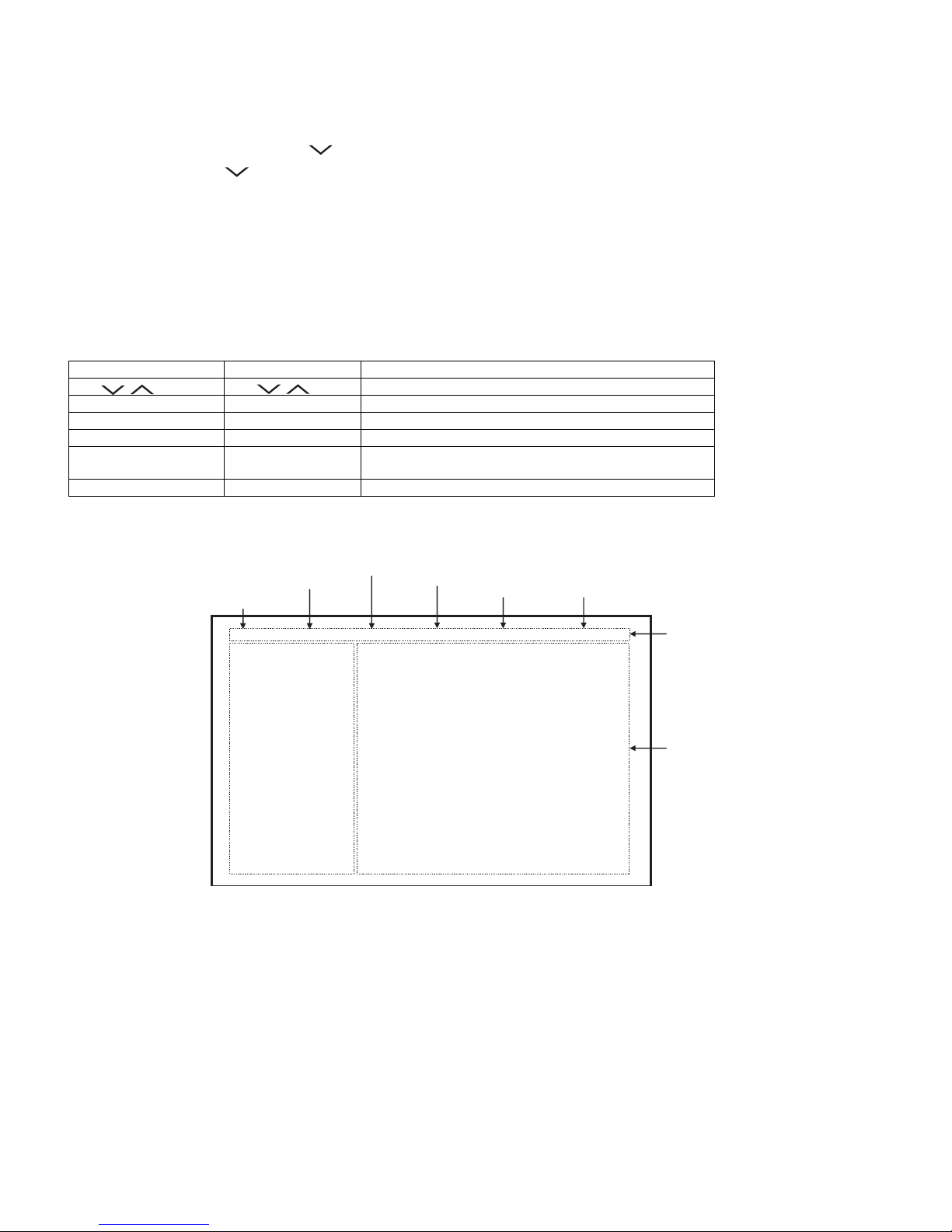
(3) Current selected input
(2) Current page title
(4) Current color system
(1) Current page/ (5) Destination
(6) LCD Panel size/Speaker type
Total pages
1/26 [INFO] INPUT5 AUTO USA 46_UNDER
MAIN Version 0.95 ( U 2006/02/02 1)
BOOT Version OLYM0.92
Monitor Version 0.88
EQ DATACHECKSUM ROM (8) Parameters
TEMPAERATURE 7B
LAMP ERROR 0
NORMAL STANDBY CAUSE
0
ERROR STANDBY CAUSE 1) 0 2) 0 3) 0
00H 00M 00H 00M 00H 00M
4) 0 5) 0
00H 00M 00H 00M
(7) Adjustment
process menu
header
(LC-46D62U: 46_UNDER)
(LC-52D62U: 52_UNDER)
LC-46D62U/LC-52D62U
5 – 6
5. List of adjustment process mode menu
The character string in brackets [ ] will appear as a page title in the adjustment process menu header.
Page Line Item Description Remarks (adjustment detail, etc.)
1 [INFO]
1 MAIN Version Main software version
2BOOT Version
3 Monitor Version Monitor software version
4 EQ DATA CHECKSUM Audio data checksum
5 TEMPERATURE CPU temperature
6 LAMP ERROR Number of termination due to lamp error
7 NORMAL STANDBY CAUSE Refer to *1 under the list for details
8 ERROR STANDBY CAUSE Refer to *2 under the list for details
2 [INIT]
1 INDUSTRY INIT (Cause)
2 INDUSTRY INIT Initialization to factory settings .
3 HOTELMODE Hotel mode
4 Center Acutime Accumulated main operation time
5 RESET Reset
6 BacklightAcutime Accumulated monitor operation time
7 RESET Reset
8 LAMP ERROR RESET Reset LAMP ERROR
9 VIC XPOS X-coordinate setting for VIC READ
10 VIC YPOS Y-coordinate setting for VIC READ
11 VIC COLOR Collected color data setting for VIC READ
12 VIC SIGNAL TYPE Signal type setting for VIC READ
13 VIC READ Picture level acquisition function Level appears in green on the upper right.
3 [N358MAIN]
1 N358 ALL ADJ CVBS and TUNER signal level adjustment
2 N358 MAIN ADJ CVBS signal level adjustment
3 TUNER DAC ADJ TUNER signal level adjustment
4 N358 MAIN CONTRAST CVBS and TUNER contrast adjustment values
5 TUNER A DAC TUNER adjustment value
4 [TUNER TEST]
1 TUNER VCHIP TEST(69ch) Tuning test and VCHIP test (69 ch)
2 TUNER VCHIP TEST(7ch) Tuning test and VCHIP test (7 ch)
3 TUNER VCHIP TEST(10ch) Tuning test and VCHIP test (10 ch)
4 TUNER VCHIP TEST(15ch) Tuning test and VCHIP test (15 ch)
5 [COMP15KMAIN]
1 COMP15K MAIN ADJ Component 15K picture level adjustment (main)
2 COMP15K MAIN CONTRAST Contrast adjustment value
3 COMP15K MAIN Cb GAIN Cb GAIN adjustment value
4 COMP15K MAIN Cr GAIN Cr GAIN adjustment value
5 COMP15K Y OFFSET Y OFFSET adjustment value
6 COMP15K Cb GAIN Cb OFFSET adjustment value
7 COMP15K Cr GAIN Cr OFFSET adjustment value
6 [HDTV]
1 HDTV ADJ Component Hi-Vision picture level adjustment
2 CONTRAST Contrast adjustment value
3 Cb GAIN Cb GAIN adjustment value
4 Cr GAIN Cr GAIN adjustment value
5 HDTV Y OFFSET Y OFFSET adjustment value
6 HDTV Cb OFFSET Cb OFFSET adjustment value
7 HDTV Cr OFFSET Cr OFFSET adjustment value
7 [M GAMMA IN]
1 MONITOR GAMMA IN 1 Standard value 1(WBI10184) Adjustment gradation setting.
2 MONITOR GAMMA IN 2 Standard value 2(WBI20352)
3 MONITOR GAMMA IN 3 Standard value 3(WBI30528)
4 MONITOR GAMMA IN 4 Standard value 4(WBI40656)
5 MONITOR GAMMA IN 5 Standard value 5(WBI50800)
6 MONITOR GAMMA IN 6 Standard value 6(WBI60928)
7 GAMMA WRITE WB adjustment data writing
8 GAMMA RESET WB adjustment data reading
LC-46D62U/LC-52D62U
5 – 7
8 [M GAMMA R1]
1 MONITOR GAMMA R 1 WB adjustment Point 1, R adjustment value Parameter for six-point adjustment
2 MONITOR GAMMA G 1 WB adjustment Point 1, G adjustment value
3 MONITOR GAMMA B 1 WB adjustment Point 1, B adjustment value
4 MONITOR GAMMA R 2 WB adjustment Point 2, R adjustment value
5 MONITOR GAMMA G 2 WB adjustment Point 2, G adjustment value
6 MONITOR GAMMA B 2 WB adjustment Point 2, B adjustment value
7 MONITOR GAMMA R 3 WB adjustment Point 3, R adjustment value
8 MONITOR GAMMA G 3 WB adjustment Point 3, G adjustment value
9 MONITOR GAMMA B 3 WB adjustment Point 3, B adjustment value
10 GAMMA WRITE WB adjustment data writing
11 GAMMA RESET WB adjustment data reading
9 [M GAMMA R4]
1 MONITOR GAMMA R 4 WB adjustment Point 4, R adjustment value Parameter for six-point adjustment
2 MONITOR GAMMA G 4 WB adjustment Point 4, G adjustment value
3 MONITOR GAMMA B 4 WB adjustment Point 4, B adjustment value
4 MONITOR GAMMA R 5 WB adjustment Point 5, R adjustment value
5 MONITOR GAMMA G 5 WB adjustment Point 5, G adjustment value
6 MONITOR GAMMA B 5 WB adjustment Point 5, B adjustment value
7 MONITOR GAMMA R 6 WB adjustment Point 6, R adjustment value
8 MONITOR GAMMA G 6 WB adjustment Point 6, G adjustment value
9 MONITOR GAMMA B 6 WB adjustment Point 6, B adjustment value
10 GAMMA WRITE WB adjustment data writing
11 GAMMA RESET WB adjustment data reading
10 [SOUND 1]
1 AUDIO SELECT
2 INPUT_TRIM_SP
3 INPUT_TRIM_HP
4 CLIPPER_LEVEL
5ANGLE
6 MASTER_VOLUME
7 SCART_PRESCALE
8 FM_AM_PRESCALE
9 I2S1_PRESCALE
10 SCART1_VOLUME
11 SCART2_VOLUME
11 [SOUND 2]
1 AIN1_ADC_VOLUME
2 AIN2_ADC_VOLUME
3 AIN3_ADC_VOLUME
4 AIN4_ADC_VOLUME
5 AIN5_ADC_VOLUME
6 AIN6_ADC_VOLUME
12 [SOUND 3]
1 SUB_VOLUME_SURROUND
2SUB_VOLUME_FLAT
3 SUB_VOLUME_EQ
4 SUB_VOLUME_HP
5 SUB_VOLUME_HP_CENTERSP
6 SUB_VOLUME_CENTERSP_EQ
7 SUB_VOLUME_CENTERSP_FLAT
8 BBE_HF_ADJUST
9 BBE_LEVEL
10 BBE_MACH3_F0
11 BBE_MACH3_Q
12 BBE_MACH3_GAIN
Page Line Item Description Remarks (adjustment detail, etc.)
LC-46D62U/LC-52D62U
5 – 8
13 [SOUND 4]
1EQ_MODE
2 PEQ1_F0
3 PEQ1_Q
4 PEQ1_GAIN
5 PEQ2_F0
6 PEQ2_Q
7 PEQ2_GAIN
8 PEQ3_F0
9 PEQ3_Q
10 PEQ3_GAIN
11 PEQ4_F0
12 PEQ4_Q
13 PEQ4_GAIN
14 [SOUND 5]
1 PEQ5_F0
2 PEQ5_Q
3 PEQ5_GAIN
4 EALA_GAIN
15 [M OPC1]
1 BRIGHTNESS DA0
2 BRIGHTNESS DA1
3 BRIGHTNESS DA2
4 BRIGHTNESS DA3
5 BRIGHTNESS DA4
6 BRIGHTNESS DA5
7 BRIGHTNESS DA6
8 BRIGHTNESS DA7
9 BRIGHTNESS DA8
10 BRIGHTNESS DA9
11 BRIGHTNESS DA10
12 BRIGHTNESS DA11
16 [M OPC2]
1 BRIGHTNESS DA12
2 BRIGHTNESS DA13
3 BRIGHTNESS DA14
4 BRIGHTNESS DA15
5 BRIGHTNESS DA16
6 BRIGHTNESS DA17
7 BRIGHTNESS DA18
8 BRIGHTNESS DA19
9 BRIGHTNESS DA20
10 BRIGHTNESS DA21
11 BRIGHTNESS DA22
17 [M OPC3]
1 BRIGHTNESS DA23
2 BRIGHTNESS DA24
3 BRIGHTNESS DA25
4 BRIGHTNESS DA26
5 BRIGHTNESS DA27
6 BRIGHTNESS DA28
7 BRIGHTNESS DA29
8 BRIGHTNESS DA30
9 BRIGHTNESS DA31
10 BRIGHTNESS DA32
Page Line Item Description Remarks (adjustment detail, etc.)
 Loading...