

Page 1
TopPage
LC-37DW99U 1st
SERVICE MANUAL
No. S77L3LC37DW99
LCD COLOR TELEVISION
MODEL
In the interests of user-safety (Required by safety regulations in some countries) the set should
be restored to its original condition and only parts identical to those specified should be used.
LC-37DW99U
OUTLINE
This model is based on the LC-37D62U and is changed some parts. This Service Manual covers the modifications
alone. For the other points, refer to the LC-32/37D62U (No. S17A9LC32D62U) Service Manual.
CONTENTS
OUTLINE AND DIFFERENCES FROM BASE MODEL
OUTLINE.................................................................... i
LIST OF CHANGED PARTS...................................... i
SAFETY PRECAUTION
IMPORTANT SERVICE SAFETY
PRECAUTION........................................................... ii
PRECAUTIONS A PRENDRE LORS DE LA
REPARATION ...........................................................iii
PRECAUTIONS FOR USING LEAD-FREE
SOLDER .................................................................. iv
Parts Guide
Parts marked with " " are important for maintaining the safety of the set. Be sure to replace these parts with specified ones for maintaining the
safety and performance of the set.
This document has been published to be used for
after sales service only.
The contents are subject to change without notice.
Page 2
LC-37DW99U 1st
LC-37DW99U 1st
OUTLINE AND DIFFERENCES FROM BASE MODEL
Service Manual
OUTLINE
This model is based on the LC-37D62U and is changed some parts. This Service Manual covers the modifications
alone. For the other points, refer to the LC-32/37D62U (No. S17A9LC32D62U) Service Manual.
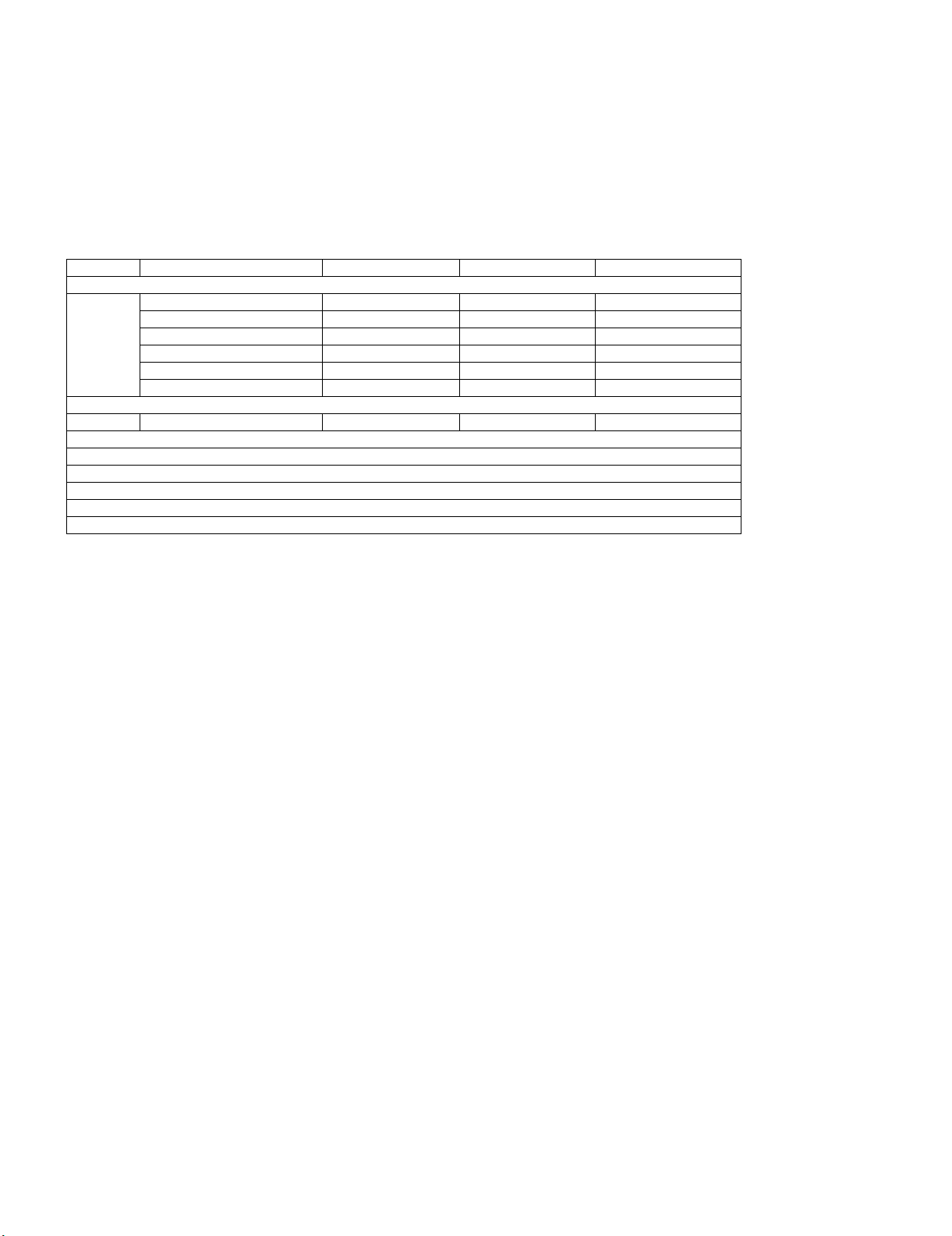
LIST OF CHANGED PARTS
Ref. No. Description LC-37D62U LC-37DW99U Note
PRINTED WIRING BOARD ASSEMBLIES
R/C, LED Unit DUNTKD909FM02 ← —
KEY Unit DUNTKD910FM02 ← —
MAIN Unit DUNTKE028FM06 ← —
TERMINAL Unit DUNTKD999FM07 ← —
POWER Unit RDENCA203WJQZ ← —
LCD PANEL
37" LCD Panel Module Unit R1LK370D3LZ20Z ← —
CABINET AND MECHANICAL PARTS
Please refer to a Parts list
PACKING PARTS AND ACCESSORIES
Please refer to a Parts list
i
Page 3
LC-37DW99U 1st
LC-37DW99U 1st
SAFETY PRECAUTION
Service Manual
IMPORTANT SERVICE SAFETY PRECAUTION
Service work should be performed only by qualified service technicians who are thoroughly familiar with all safety checks and the
servicing guidelines which follow:
WARNING
1. For continued safety, no modification of any circuit should be
attempted.
2. Disconnect AC power before servicing.
CAUTION: FOR CON T I NUE D PROTECTION
AGAINST A RISK OF FIRE REPLACE ONLY WITH
SAME TYPE FUSE.
F701 (125V 8A)
F4702 (250V 6.3A)
• Use an AC voltmeter having with 5000 ohm per volt, or higher, sensitivity or measure the AC voltage drop across the resistor.
• Connect the resistor connection to all exposed metal parts having a
return to the chassis (antenna, metal cabinet, screw heads, knobs
and control shafts, escutcheon, etc.) and measure the AC voltage
drop across the resistor.
All checks must be repeated with the AC cord plug connection
reversed. (If necessary, a nonpolarized adaptor plug must be used
only for the purpose of completing these checks.)
Any reading of 0.75 Vrms (this corresponds to 0.5 mA rms AC.) or
more is excessive and indicates a potential shock hazard which
must be corrected before returning the monitor to the owner.
DVM
BEFORE RETURNING THE RECEIVER (Fire &
Shock Hazard)
Before returning the receiver to the user, perform the following
safety checks:
3. Inspect all lead dress to make certain that leads are not pinched,
and check that hardware is not lodged between the chassis and
other metal parts in the receiver.
4. Inspect all protective devices such as non-metallic control knobs,
insulation materials, cabinet backs, adjustment and compartment
covers or shields, isolation resistor-capacitor networks, mechanical
insulators, etc.
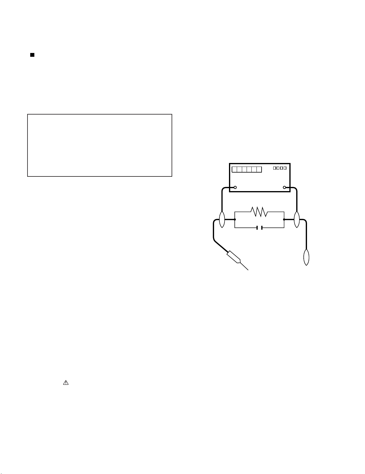
5. To be sure that no shock hazard exists, check for leakage current in
the following manner.
• Plug the AC cord directly into a 120 volt AC outlet.
• Using two clip leads, connect a 1.5k ohm, 10 watt resistor paralleled by a 0.15µF capacitor in series with all exposed metal cabinet
parts and a known earth ground, such as electrical conduit or electrical ground connected to an earth ground.
///////////////////////////////////////////////////////////////////////////////////////////////////////////////////////////////////////////////////////////////////////////////////////////////////////////////////////////////////////////
TO EXPOSED
METAL PARTS
AC SCALE
1.5k ohm
10W
0.15µF
TEST PROBE
CONNECT TO
KNOWN EARTH
GROUND
SAFETY NOTICE
Many electrical and mechanical parts in LCD color television have
special safety-related characteristics.
These characteristics are often not evident from visual inspection, nor
can protection afforded by them be necessarily increased by using
replacement components rated for higher voltage, wattage, etc.
Replacement parts which have these special safety characteristics are
identified in this manual; electrical components having such features
are identified by " " and shaded areas in the Replacement Parts List
and Schematic Diagrams.
///////////////////////////////////////////////////////////////////////////////////////////////////////////////////////////////////////////////////////////////////////////////////////////////////////////////////////////////////////////
For continued protection, replacement parts must be identical to those
used in the original circuit.
The use of a substitute replacement parts which do not have the same
safety characteristics as the factory recommended replacement parts
shown in this service manual, may create shock, fire or other hazards.
ii
Page 4
LC-37DW99U 1st
PRECAUTIONS A PRENDRE LORS DE LA REPARATION
Ne peut effectuer la réparation qu' un technicien spécialisé qui s'est parfaitement accoutumé à toute vérification de sécurité et aux
conseils suivants.
•
AVERTISSEMENT
1.
N'entreprendre aucune modification de tout circuit. C'est dangereux.
2.
Débrancher le récepteur avant toute réparation.
PRECAUTION: POUR LA PROTECTION CONTINUE CONTRE LES RISQUES D'INCENDIE,
REMPLACER LE FUSIBLE
F701 (125V 8A)
F4702 (250V 6.3A)
VERIFICATIONS CONTRE L'INCEN-DIE ET LE
CHOC ELECTRIQUE
Avant de rendre le récepteur à l'utilisateur, effectuer les vérifications suivantes.
Inspecter tous les faisceaux de câbles pour s'assurer que les fils
3.
ne soient pas pincés ou qu'un outil ne soit pas placé entre le châssis et les autres pièces métalliques du récepteur.
4.
Inspecter tous les dispositifs de protection comme les boutons de
commande non-métalliques, les isolants, le dos du coffret, les couvercles ou blindages de réglage et de compartiment, les réseaux
de résistancecapacité, les isolateurs mécaniques, etc.
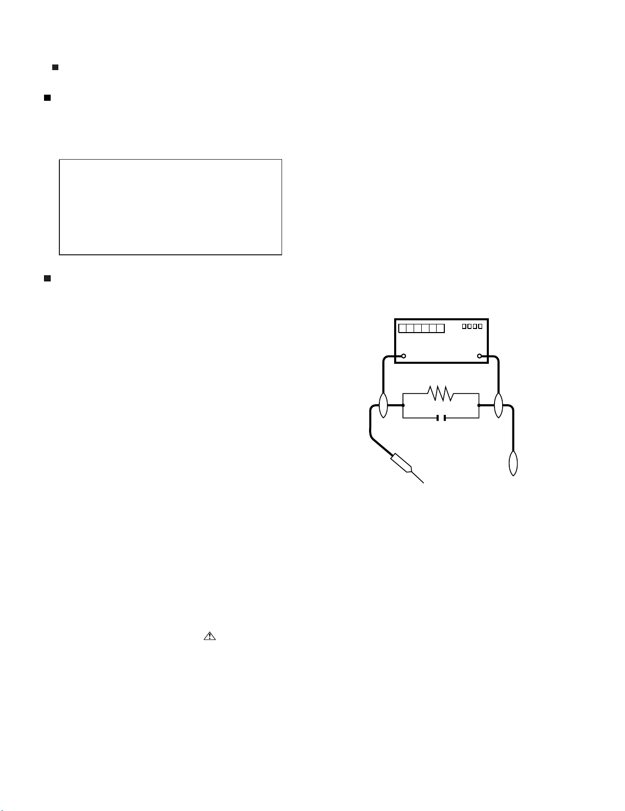
5.
S'assurer qu'il n'y ait pas de danger d'électrocution en vérifiant la
fuite de courant, de la facon suivante:
•
Brancher le cordon d'alimentation directem-ent à une prise de courant de 120V. (Ne pas utiliser de transformateur d'isolation pour
cet essai).
A l'aide de deux fils à pinces, brancher une résistance de 1.5 kΩ
10 watts en parallèle avec un condensateur de 0.15µF en série
avec toutes les pièces métalliques exposées du coffret et une terre
connue comme une conduite électrique ou une prise de terre
branchée à la terre.
•
Utiliser un voltmètre CA d'une sensibilité d'au moins 5000Ω/V pour
mesurer la chute de tension en travers de la résistance.
•
Toucher avec la sonde d'essai les pièces métalliques exposées qui
présentent une voie de retour au châssis (antenne, coffret métallique, tête des vis, arbres de commande et des boutons, écusson,
etc.) et mesurer la chute de tension CA en-travers de la résistance.
Toutes les vérifications doivent être refaites après avoir inversé la
fiche du cordon d'alimentation. (Si nécessaire, une prise
d'adpatation non polarisée peut être utilisée dans le but de terminer ces vérifications.)
La tension de pointe mesurèe ne doit pas dépasser 0.75V (correspondante au courant CA de pointe de 0.5mA).
Dans le cas contraire, il y a une possibilité de choc électrique qui
doit être supprimée avant de rendre le récepteur au client.
DVM
ECHELLE CA
1.5k ohm
10W
µ
F
0.15
SONDE D'ESSAI
AUX PIECES
METALLIQUES
EXPOSEES
/////////////////////////////////////////////////////////////////////////////////////////////////////////////////////////////////////////////////////////////////////////////////////////////////////////////////////////////////////////////
BRANCHER A UNE
TERRE CONNUE
AVIS POUR LA SECURITE
De nombreuses pièces, électriques et mécaniques, dans les téléviseur ACL présentent des caractéristiques spéciales relatives à la sécurité, qui ne sont souvent pas évidentes à vue. Le degré de protection ne peut pas être nécessairement augmentée en utilisant des
pièces de remplacement étalonnées pour haute tension, puissance,
etc.
Les pièces de remplacement qui présentent ces caractéristiques sont
identifiées dans ce manuel; les pièces électriques qui présentent ces
particularités sont identifiées par la marque " " et hachurées dans la
liste des pièces de remplacement et les diagrammes schématiques.
/////////////////////////////////////////////////////////////////////////////////////////////////////////////////////////////////////////////////////////////////////////////////////////////////////////////////////////////////////////////
Pour assurer la protection, ces pièces doivent être identiques à celles
utilisées dans le circuit d'origine. L'utilisation de pièces qui n'ont pas
les mêmes caractéristiques que les pièces recommandées par l'usine,
indiquées dans ce manuel, peut provoquer des électrocutions, incendies, radiations X ou autres accidents.
iii
Page 5
LC-37DW99U 1st
PRECAUTIONS FOR USING LEAD-FREE SOLDER
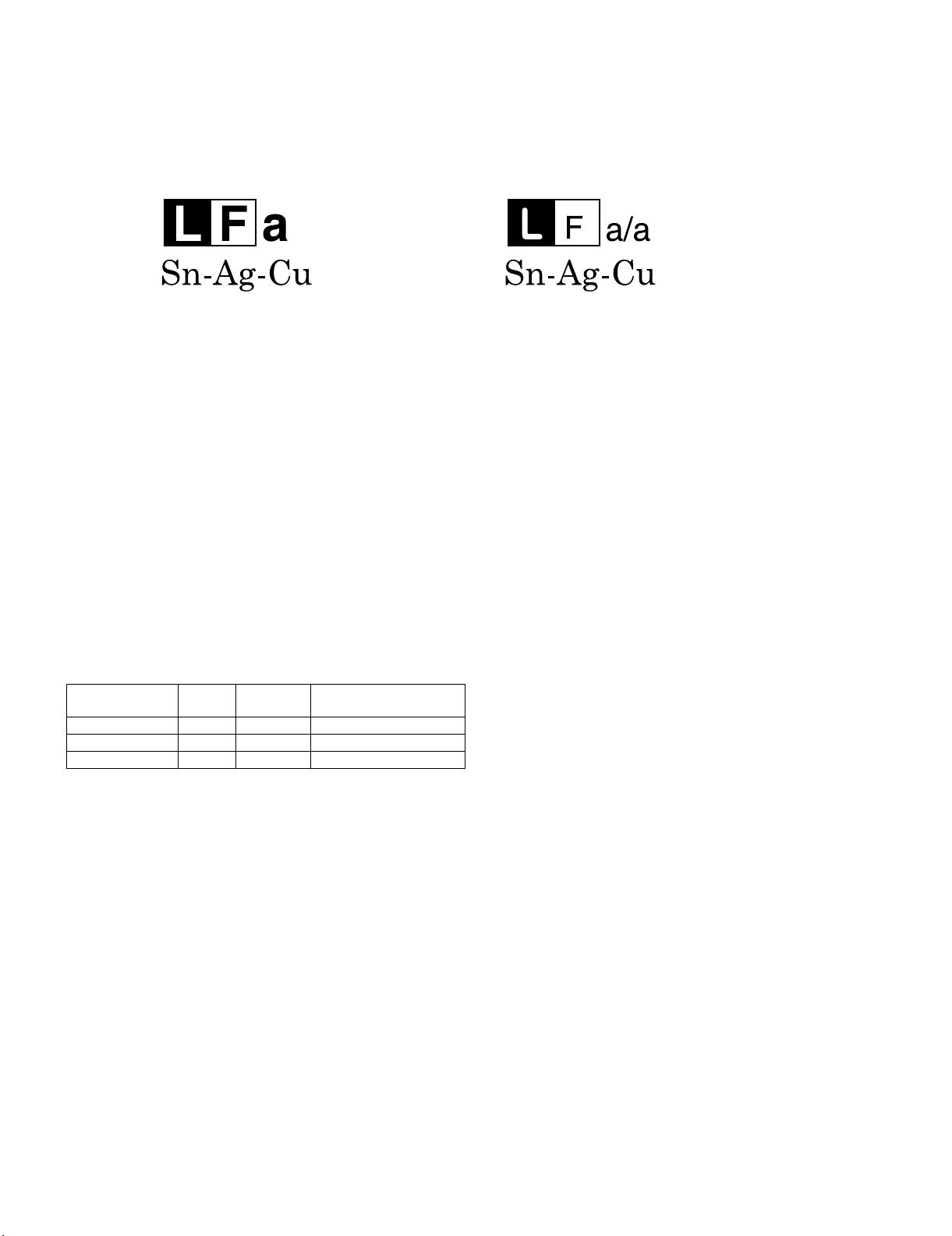
Employing lead-free solder
• “PWBs” of this model employs lead-free solder. The LF symbol indicates lead-free solder, and is attached on the PWBs and service manuals. The
alphabetical character following LF shows the type of lead-free solder.
Example:
Indicates lead-free solder of tin, silver and copper. Indicates lead-free solder of tin, silver and copper.
Using lead-free wire solder
• When fixing the PWB soldered with the lead-free solder, apply lead-free wire solder. Repairing with conventional lead wire solder may cause damage or accident due to cracks.
As the melting point of lead-free solder (Sn-Ag-Cu) is higher than the lead wire solder by 40 °C, we recommend you to use a dedicated soldering
bit, if you are not familiar with how to obtain lead-free wire solder or soldering bit, contact our service station or service branch in your area.
Soldering
• As the melting point of lead-free solder (Sn-Ag-Cu) is about 220 °C which is higher than the conventional lead solder by 40 °C, and as it has poor
solder wettability, you may be apt to keep the soldering bit in contact with the PWB for extended period of time. However, Since the land may be
peeled off or the maximum heat-resistance temperature of parts may be exceeded, remove the bit from the PWB as soon as you confirm the
steady soldering condition.
Lead-free solder contains more tin, and the end of the soldering bit may be easily corroded. Make sure to turn on and off the power of the bit as
required.
If a different type of solder stays on the tip of the soldering bit, it is alloyed with lead-free solder. Clean the bit after every use of it.
When the tip of the soldering bit is blackened during use, file it with steel wool or fine sandpaper.
• Be careful when replacing parts with polarity indication on the PWB silk.
Lead-free wire solder for servicing
PARTS CODE
ZHNDAi123250E BL J φ0.3mm 250g (1roll)
ZHNDAi126500E BK J φ0.6mm 500g (1roll)
ZHNDAi12801KE BM J φ1.0mm 1kg (1roll)
PRICE
RANK
PART
DELIVERY
DESCRIPTION
iv
Page 6

LC-37DW99U 1st
MEMO
v
Page 7

PartsGuide
Note:
The reference numbers on the PWB
are arranged in alphabetical order.
PARTS GUIDE
No. S77L3LC37DW99
MODEL
CONTENTS
LC-37DW99U
LC-37DW99U 1st
[1] PRINTED WIRING BOARD ASSEMBLIES
(NOT REPLACEMENT ITEM)
[2] PRINTED WIRING BOARD ASSEMBLIES
[3] LCD PANEL (NOTE: THE PARTS HERE
SHOWN ARE SUPPLIED AS AN ASSEMBLY
BUT NOT INDEPENDENTLY.)
[4] CABINET AND MECHANICAL PARTS
[5] SUPPLIED ACCESSORIES
[6] PACKING PARTS (NOT REPLACEMENT ITEM)
[7] SERVICE JIG (USE FOR SERVICING)
Parts marked with " " are important for maintaining the safety of the set. Be sure to replace these
parts with specified ones for maintaining the safety and performance of the set.
This document has been published to be used
for after sales service only.
The contents are subject to change without notice.
Page 8

LC-37DW99U 1st
NO. PARTS CODE
PRICE
RANK
NEW
MARK
PAR T
DELIVERY
DESCRIPTION
[1] PRINTED WIRING BOARD ASSEMBLIES (NOT REPLACEMENT ITEM)
N DUNTKD909FM02 - - R/C, LED Unit
N DUNTKD910FM02 - - KEY Unit
N DUNTKD999FM07 - N - TERMINAL Unit
[2] PRINTED WIRING BOARD ASSEMBLIES
N DUNTKE028FM06 CN N R MAIN Unit
!
N RDENCA203WJQZ BP X POWER Unit
[3] LCD PANEL (NOTE: THE PARTS HERE SHOWN ARE SUPPLIED AS AN ASSEMBLY BUT NOT INDEPEN-
DENTLY.)
N R1LK370D3LZ20Z EC N J 37" Wide LCD Panel Module Unit
2
Page 9
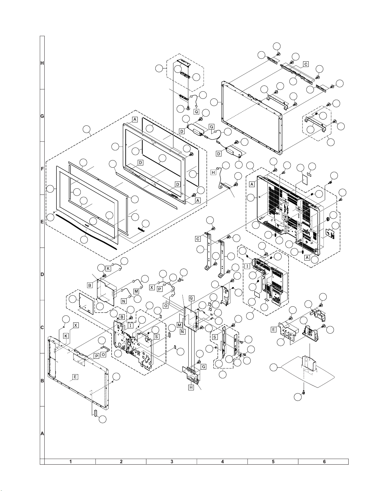
[4] CABINET AND MECHANICAL PARTS
39
40
8
40
1
3
4
3-1
3-2
1-1
1-2
1-3
1-5
1-6
1-9
1-9
1-11
1-11
1-10
1-9
1-9
1-9
1-9
1-7
1-7
1-8
1-8
2
2-1
2-2
2-3
2-4
2-5
2-5
2-5
2-5
2-5
2-5
5
5-1
5-2
5-2
5-2
5-3
5-4
6
6-1
6-2
7
7-1
7-2
8-1
8-2
8-2
8-3
8-4
9
11
10
12
13
14
15
16
17
17
18
18
19
20
20
21
23
24
25
26
26
28
27
29
42
43
44
30
31
32
33
34
35
36
37
38
41
45
45
45
45
45
46
46
48
49
49
50
50
50
51
51
53
53
54
KEY Unit
R/C, LED Unit
MAIN Unit
TERMINAL Unit
POWER Unit
47
47
47
47
47
47
47
47
47
47
47
47
47
1-4
22
22
52
LC-37DW99U 1st
3
Page 10

LC-37DW99U 1st
NO. PARTS CODE
PRICE
RANK
NEW
MARK
PAR T
DELIVERY
[4] CABINET AND MECHANICAL PARTS
1 CCABAB690WJ03 N X Cabinet A Ass'y
1-1 Not Available - - Cabinet A
1-2 GCOVAB821WJSA X LED Cover
1-3 GCOVAC044WJKB N X Front Cover
1-4 Not Available - - SHARP Badge
1-5 HDECSA007WJSB AP X Shine Trim
1-6 HPNLSA123WJSA AY X Speaker Net
1-7 PSPAHA416WJZZ AC J Spacer, x2
1-8 PSPAHA801WJZZ X Spacer, x2
1-9 PSPAZB074WJZZ X Spacer, x6
1-10 TLABZA635WJZZ AC J POP Label
1-11 XJPS730P08WS0 AA J Screw for Front Cover, x5
2 CCABBB022WJ01 BQ N X Cabinet B Ass'y
2-1 Not Available - N - Cabinet B
2-2 HINDPC317WJSA N X Terminal Label
2-3 LHLDWA012WJKZ AC J Wire Holder
2-4 LHLDWA057WJKZ AE J Wire Holder
2-5 PSPAHB078WJZZ X Spacer for Speaker, x6
3 CCOVAB929WJ01 AM X Top Cover Ass'y
3-1 Not Available - - Top Cover
3-2 JBTN-A614WJKA X Operation Button
4 R1LK370D3LZ20Z EC N J 37" Wide LCD Panel Module Unit
5 CSLDMB075WJ01 AX N X Main Shield Ass'y
5-1 Not Available - N - Main Shield
5-2 LHLDWA102WJKZ AB J Wire Holder, x3
5-3 PMLT-A423WJZZ AD N X Spacer
5-4 PSPAHB078WJZZ X Spacer
6 CANGKA957WJ01 AL X Rug Angle Bottom R Ass'y
6-1 Not Available - N - Rug Angle Bottom R
6-2 LHLDWA120WJKZ AB J Wire Holder
7 CANGKA948WJ01 AN N X Jack Angle Ass'y
7-1 Not Available - N - Jack Angle (Long)
7-2 HINDPC316WJSA N X Jack Indicator Plate
8 CCHSMA403WJ03 X
8-1 Not Available - N - Chassis Tray
8-2 LHLDWA102WJKZ AB J Wire Holder, x3
8-3 LHLDWA120WJKZ AB J Wire Holder
8-4 PZETKA219WJZZ X Insulator
9 GCOVAA678WJKA AE J SD Card Cover
10 GCOVAC011WJKA AP N X Stand Area Cover
11 HINDPB715WJSA AF X Terminal Label
12 HINDPC617WJSA N X Model Label
13 LANGKA865WJ3W AN X LCD Angle L
14 LANGKA913WJM1 BC X Stand Fix Angle
15 LANGKA914WJFW AL X Stand Assist Angle
16 LANGKA957WJFW AL X Rug Angle Bottom L
17 LANGKA958WJN1 AQ N X Center Angle, x2
18 LANGKB018WJFW AF X LCD Angle S, x2
19 LHLDW1003PEZZ AA J Wire Holder
20 LX-HZA003WJFN AC J Screw for SP-BOX, x4
21 LX-NZ3047GEZZ AA J Nut
22 LX-BZA176WJF9 N X Screw for Stand, x9
23 PCLICA004WJKZ AC J Push Rivet, x2
24 PRDARA424WJFW BB J Heat Sink
25 PSLDMA584WJZZ AE J Shield
26 PSPAZA917WJKZ AH J Spacer, x2
27 PSPAZB030WJKZ AB J Spacer
28 PSPAZB192WJKZ AF J Spacer
29 QCNCWA496WJZZ AK J Connector (F-RCA)
30 QCNW-E634WJQZ AE J Connecting Cord (LA)
31 QCNW-E894WJQZ AP J Connecting Cord (LP)
32 QCNW-F596WJQZ AL N X Connecting Cord (SP)
33 QCNW-F597WJQZ AR N X Connecting Cord (RA)
34 QCNW-F598WJQZ AL N X Connecting Cord (LB)
35 QCNW-E249WJPZ AH J Connecting Cord (TUNER)
36 QCNW-E258WJQZ AG J Connecting Cord (PD)
37 QCNW-E266WJQZ AF J Connecting Cord (KM)
QCNW-E902WJQZ AH J Connecting Cord (PH)
38
39 QEARZA069WJZZ AH J Earth Plate
40 QEARZA080WJZZ AD J Earth Plate, x2
41 QPWBHE120WJQZ AX N X Connecting Cord (LV)
42 RSP-ZA215WJZZ AY X Speaker (Left)
43 RSP-ZA216WJZZ AY X Speaker (Right)
44 Not Available - - No. Label
45 XBBS740P06000 AA J Screw for Angle, x6
46 XBBS930P06000 AA J Screw for Cabinet B, x4
47 XBPS730P06WS0 AA J Screw for PWB, x15 Angle, x26
48 XBPS830P06000 AA J Screw for HDMI, x2
49 XEBS930P10000 AA J Screw for LED, x2 KEY, x2
50 XEBS940P10000 AB J Screw for Panel, x4
51 XEBS940P16000 AB J Screw for Cabinet B, x10
52 CDAI-A348WJ04 N X Stand Unit
52-1 CDAI-A348WJ03 N X Stand Base Ass'y
52-1-1 Not Available - N - Stand Base
52-1-2 LANGKA955WJZZ X Base Angle
Chassis Tray Ass'y
DESCRIPTION
4
Page 11

LC-37DW99U 1st
NO. PARTS CODE
PRICE
RANK
NEW
MARK
PAR T
DELIVERY
[4] CABINET AND MECHANICAL PARTS
52-1-3 PSPAZA949WJZZ X Leg Cushion A, x4
52-1-4 PSPAZA950WJZZ X Leg Cushion B, x2
52-1-5 XEBS940P10000 AB J Screw for Cover/Angle, x6
53 LHLDWA139WJKZ AC J Wire Holder, x2
54 QCNW-F305WJQZ AF X Connecting Cord (MODEL SELECT)
55 PMLT-A367WJZZ AB J Spacer
56 PSLDMA840WJZZ AD J Shield
57 GDAI-A333WJSA X Stand Support
[5] SUPPLIED ACCESSORIES
X1
X8 X9 X10
Cable Band
Operation Manual
X2
Cable Clamp
"AAA" Size Battery
X3
AC Cord
Stand Unit
DESCRIPTION
X4
Remote Control Unit
NO. PARTS CODE
PRICE
RANK
NEW
MARK
PAR T
DELIVERY
[5] SUPPLIED ACCESSORIES
X1 LHLDWA083WJ00 AD J Cable Band
X2 LHLDWA131WJKZ AE J Cable Clamp
!
X3 QACCDA039WJPZ AQ J AC Cord
X4 RRMCGA535WJSA AZ J Remote Control Unit
X5 TCADEA208WJZZ AD X Enquete Card
X6 TCAUZA286WJZZ N X Caution Card
X7 TGAN-A768WJZZ AD X Extend Warranty
X8 TINS-D361WJZZ N X Operation Manual
X9 Not Available - - "AAA"Size Battery
X10 CDAI-A348WJ04 N X Stand Unit
X10-1 UKOGLA001WJZZ AB J Tool for Stand
X10-2 UCLEZA001WJZZ AD J Cleaning Cloth
X10-1 X10⁻²
DESCRIPTION
5
Page 12

LC-37DW99U 1st
[6] PACKING PARTS (NOT REPLACEMENT ITEM)
S8
S9
S7
S7
S3
S4
S5
S10
S11
S7
S2
S6
S7
S12
S1
6
Page 13

LC-37DW99U 1st
NO. PARTS CODE
PRICE
RANK
NEW
MARK
PAR T
DELIVERY
[6] PACKING PARTS (NOT REPLACEMENT ITEM)
S1 SPAKCD801WJZZ - N - Packing Case
S2 SPAKFB165WJZZ - - Stand Case
S3 SPAKFB166WJZZ - - Stand Pad
S4 SPAKPA797WJZZ - - Mirror Mat Base
S5 SPAKPA798WJZZ - - Mirror Mat Sup
S6 SPAKPA831WJZZ - - Wrapping Paper (Monitor)
S7 SPAKXB364WJZZ - - Packing Add.
S8 SSAKA0101GJZZ - - Polyethylene Bag
S9 SSAKAA032WJZZ - - Polyethylene Bag
S10 SSAKHA033WJZZ - N - Polyethylene Bag for Cloth
S11 SSAKHA035WJZZ - N - Polyethylene Bag for Screw
S12 TLABKA009WJZZ - - No. Label
[7] SERVICE JIG (USE FOR SERVICING)
N QCNW-C222WJQZ AW J Connecting Cord (80pin 100cm)
N PANEL to LCD CONTROL Unit
N QCNW-D483WJQZ AX J Connecting Cord (PH 12pin 100cm)
N MAIN to POWER Unit
N QCNW-E068WJQZ AS J Connecting Cord (PD 6pin 100cm)
N MAIN to POWER Unit
N QCNW-E343WJQZ AM J Connecting Cord (LA 3pin 100cm)
N POWER to INVERTER Unit
N QCNW-E579WJQZ AP J Connecting Cord (LB 4-8pin 100cm)
N MAIN to INVERTER Unit
N QCNW-F137WJQZ AX J Connecting Cord (LP 20pin 100cm)
N MAIN to LCD CONTROL Unit
N QCNW-E134WJQZ BG J Connecting Cord (LV 41pin 40cm)
N MAIN to LCD CONTROL Unit
N QCNW-C799WJPZ AG J Connecting Cord (Coaxial cable 150cm)
N TUNER to TERMINAL Unit
DESCRIPTION
7
Page 14

LC-37DW99U 1st
COPYRIGHT 2007 BY SHARP CORPORATION
ALL RIGHTS RESERVED.
No part of this publication may be reproduced,
stored in a retrieval system, or transmitted in
any form or by any means, electronic, mechanical,
photocopying, recording, or otherwise, without
prior written permission of the publisher.
Jul. 2007 Printed in Japan
TQ0000-S MI. KD
SHARP CORPORATION
AV Systems Group
CS Promotion Center
Yaita, Tochigi 329-2193, Japan
 Loading...