

Page 1
TopPage
LC-37D90U
SERVICE MANUAL
No. S47E8LC37D90U
SUPPLEMENT
LCD COLOR TELEVISION
MODEL
In the interests of user-safety (Required by safety regulations in some countries) the set should be restored to its original condition and only parts identical to those specified should be used.
OUTLINE
In this Service Manual, only parts in the LCD module are shown. For the other points, refer to the LC-37D90U
(S56S8LC37D90U) Service Manual.
LC-37D90U
Parts marked with " " are important for maintaining the safety of the set. Be sure to replace these parts with specified ones for maintaining the
safety and performance of the set.
This document has been published to be used for
after sales service only.
The contents are subject to change without notice.
Page 2
LC-37D90U
LC-37D90U
OUTLINE AND ADJUSTMENT
Service Manual
[1] Outline
In this Service Manual, only parts in the LCD module are shown. For the other points, refer to the LC-37D90U (S56S8LC37D90U) Service Manual.
[2] Adjustment
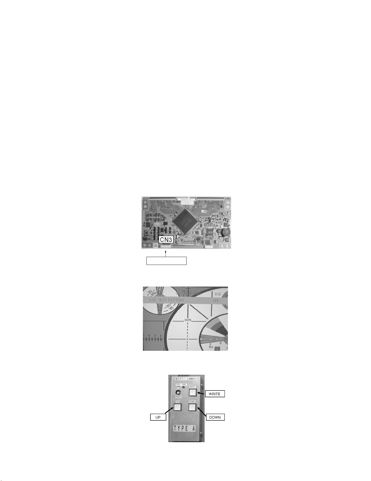
When replacing the LCD control PCB, follow these steps to adjust VCOM.
1) Remove the wire from the LCD control PCB CN3.
2) Connect a wire of the VCOM adjustment jig (electronic volume adjustment BOX) to CN3 (see Fig. 1).
3) Turn on the TV set.
4) Turn on the jig (connect to the AC).
5) Enter the process mode to display the item “LCD TEST PATTERN OFF” (see Fig. 2).
6) Press the volume up key once to display a flicker pattern.
7) Press the jig's UP/DOWN switch while looking at the screen to adjust the point so that the flicker is minimized (see Fig. 3).
8) After completing adjustment, press the WRITE switch and make sure the lamp of the WRITE button goes out. (Writing is complete when the lamp
goes out.)
9) Turn off the jig (turn the AC off).
10)Turn off the TV set.
11)Remove the jig’s wire connected to CN3.
12)Reconnect the wire of the set to CN3.
Jig connection
Fig. 1 Jig connecting location
Fig. 2 Test pattern selection screen
Fig. 3 VCOM adjustment jig (RUNTZA059WJZZ)
i
Page 3

PartsGuide
LC-37D90U
PARTS GUIDE
LCD COLOR TELEVISION
[1] LCD MODULE Assembly
MODEL
CONTENTS
LC-37D90U
Parts marked with " " are important for maintaining the safety of the set. Be sure to replace these
parts with specified ones for maintaining the safety and performance of the set.
This document has been published to be used
for after sales service only.
The contents are subject to change without notice.
Page 4

LC-37D90U
[1] LCD MODULE Assembly
15
16
18
1
7
7
2
3
4
19
5
23
20
23
24
21
22
17
8
9
10
6
10
11
12
13
14
2
Page 5

LC-37D90U
NO. PARTS CODE
PRICE
RANK
NEW
MARK
PAR T
DELIVERY
[1] LCD MODULE Assembly
1 R1LK370D3LZ1AB EZ N J LCD Module Ass'y
2 QPWBM0197TPZZ AH N J CS-FPC1,x2
3 CPWBX3348TPZC BV N J LCD CONTROL Unit
4 PSLDMA992WJFW AL N J Cover (LCD Control Unit (Top))
5 PSLDMA804WJM1 AM N J Cover (LCD Control Unit (Bottom))
6 LX-BZ2118TPZZ AA N J Screw (for Vessel), x10
7 XBPS730P06WS0 AA J Screw (for INV, LCD CONTROL), x13
8 CCHSMA310WJ01 BP N J Chassis Ass'y
9 KLMP-A127WJZZ BA N J Lamp Unit, x11
10 LHLDZA682WJKZ AX N J Lamp Holder, x2
11 PCOVUA090WJZZ BA N J Diffusion Panel
12 PSHEPA423WJZZ AU N J Reflection Sheet
13 PSHEPA424WJZZ BM N J Prism Sheet
14 PSHEPA425WJZZ BT N J Optical Sheet
15 PSLDMA953WJFW AN N J Inverter Cover
16 RUNTKA244WJZZ BM N J INVERTER Unit A
17 RUNTKA245WJZZ BG N J INVERTER Unit B
18 PSPAZB030WJKZ AB N J Inverter Spacer, x9
19 RCORFA061WJZZ AG N J Core, x2
20 PTPEZA018WJZZ AD N J PET Tape, x2
21 PZETE3914TPZZ AD N J Tape, x2
22 PZETE3915TPZZ AB N J Tape
23 PSHEP2529TPZZ AB N J Conductive Tape, x4
24 PSHEP2583TPZZ AC N J Conductive Tape
DESCRIPTION
3
Page 6

LC-37D90U
COPYRIGHT © 2007 BY SHARP CORPORATION
ALL RIGHTS RESERVED.
No Part of this publication may be reproduced,
stored in a retrieval system, or transmitted in
any from or by any means, electronic, mechanical,
photocopying, recording, or otherwise, without
prior written permission of the publisher.
TQ2192-S YT. DS
SHARP CORPORATION
AV Systems Group
CS Promotion Center
Yaita,Tochigi 329-2193, Japan
 Loading...