

Page 1
TopPage
LC-37D42U/LC-37D43U/LC-C3742U
SERVICE MANUAL
No. S47G3LC37D42U
SUPPLEMENT
LCD COLOR TELEVISION
LC-37D42U
LC-37D43U
MODELS
In the interests of user-safety (Required by safety regulations in some countries) the set should be restored to its original condition and only parts identical to those specified should be used.
OUTLINE
In this Service Manual, only parts in the LCD module are shown. For the other points, refer to the LC-37D42U/LC37D43U/LC-C3742U (S06X9LC32D42U/SX6Y9LC37D43U/SX6Y7LCC3742U) Service Manual.
New panel modules are incorporated in LC-37D42U/LC-37D43U/LC-C3742U with the Serial No. "****51112~".
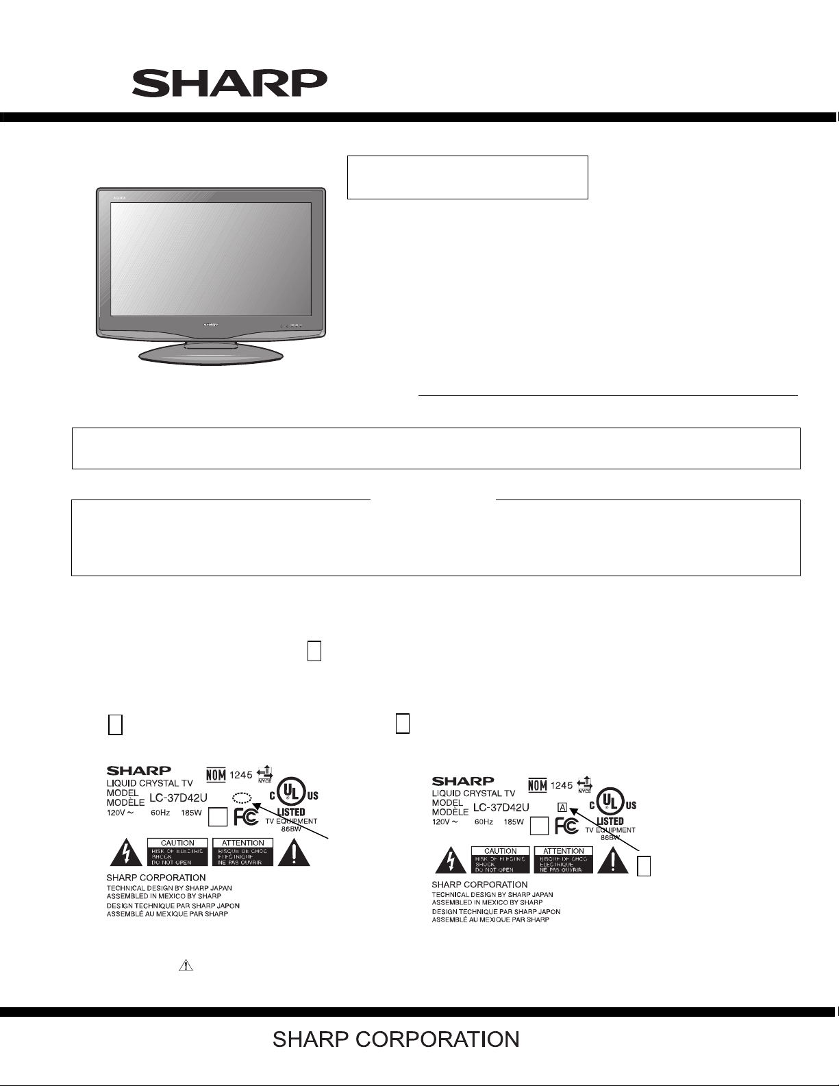
How to distinguish the model labels of new and old panel modules.
As to the new panel module, the mark A is printed on the model label.
Old panel module New panel module
No A mark on the right side of the model name A mark on the right side of the model name
Example Example
LC-C3742U
No Mark
A
Parts marked with " " are important for maintaining the safety of the set. Be sure to replace these parts with specified ones for maintaining the
safety and performance of the set.
This document has been published to be used for
after sales service only.
The contents are subject to change without notice.
Page 2
LC-37D42U/LC-37D43U/LC-C3742U
LC-37D42U (A)
OUTLINE AND ADJUSTMENT
Service Manual
[1] Outline
In this Service Manual, only parts in the LCD module are shown. For the other points, refer to the LC-37D42U/LC-37D43U/LC-C3742U
(S06X9LC32D42U/SX6Y9LC37D43U/SX6Y7LCC3742U) Service Manual.
New panel modules are incorporated in LC-37D42U/LC-37D43U/LC-C3742U with the Serial No. "****51112~".
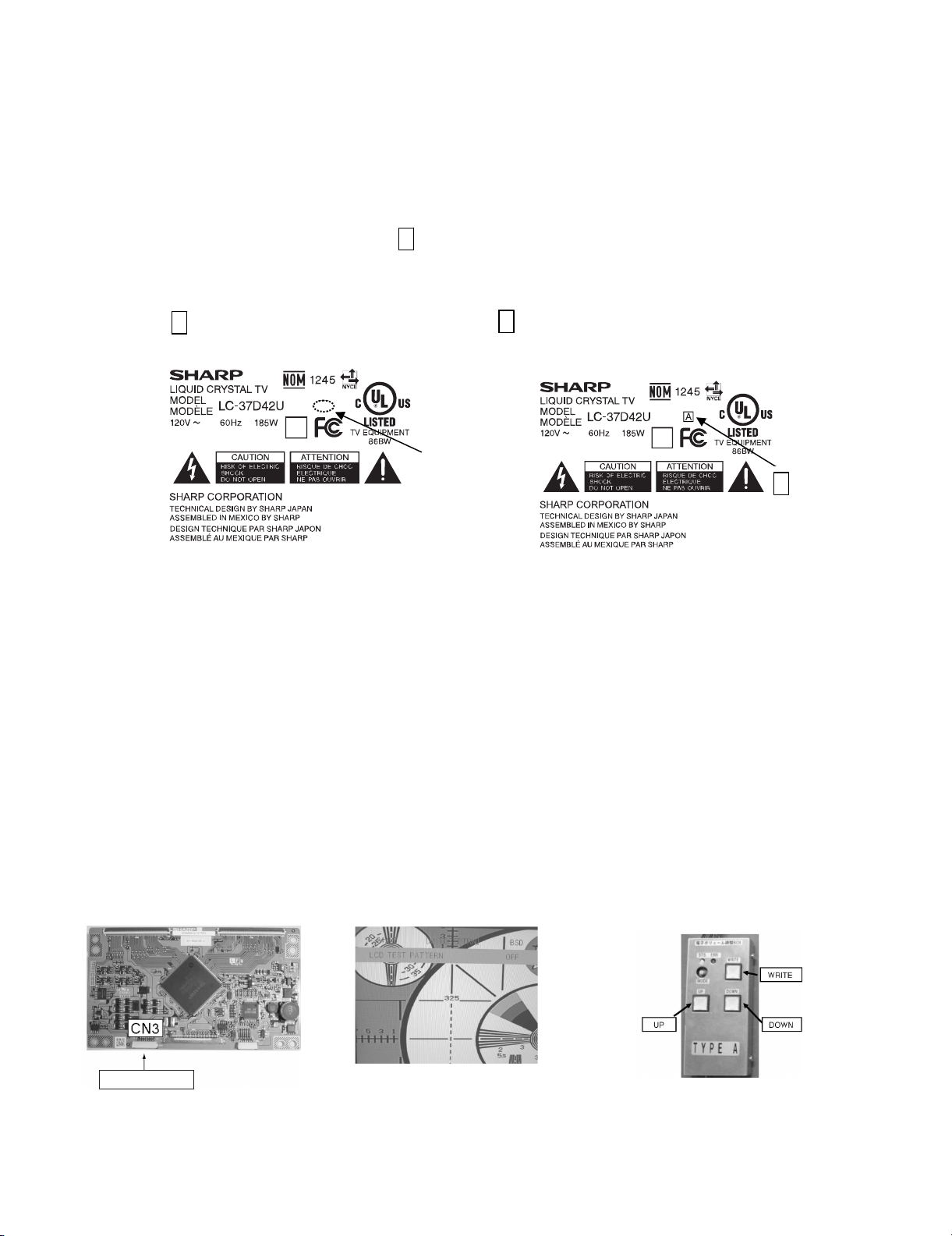
How to distinguish the model labels of new and old panel modules.
As to the new panel module, the mark A is printed on the model label.
Old panel module New panel module
No A mark on the right side of the model name A mark on the right side of the model name
Example Example
No Mark
A
[2] Adjustment
When replacing the LCD control PCB, follow these steps to adjust VCOM.
1) Remove the wire from the LCD control PCB CN3.
2) Connect a wire of the VCOM adjustment jig (electronic volume adjustment BOX) to CN3 (see Fig. 1).
3) Turn on the TV set.
4) Turn on the jig (connect to the AC).
5) Enter the process mode to display the item “LCD TEST PATTERN OFF” (see Fig. 2).
6) Press the volume up key once to display a flicker pattern.
7) Press the jig's UP/DOWN switch while looking at the screen to adjust the point so that the flicker is minimized (see Fig. 3).
8) After completing adjustment, press the WRITE switch and make sure the lamp of the WRITE button goes out. (Writing is complete when the lamp
goes out.)
9) Turn off the jig (turn the AC off).
10)Turn off the TV set.
11)Remove the jig’s wire connected to CN3.
12)Reconnect the wire of the set to CN3.
Jig connection
Fig. 1 Jig connecting location
Fig. 2 Test pattern selection screen
i
Fig. 3 VCOM adjustment jig (RUNTZA059WJZZ)
Page 3
PartsGuide
LC-37D42U/LC-37D43U/LC-C3742U
PARTS GUIDE
LCD COLOR TELEVISION
LC-37D42U
LC-37D43U
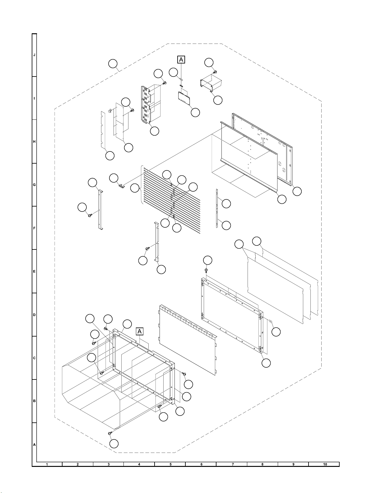
[1] LCD MODULE Assembly
MODELS
CONTENTS
LC-C3742U
Parts marked with " " are important for maintaining the safety of the set. Be sure to replace these
parts with specified ones for maintaining the safety and performance of the set.
This document has been published to be used
for after sales service only.
The contents are subject to change without notice.
Page 4
LC-37D42U/LC-37D43U/LC-C3742U
[1] LCD MODULE Assembly
30
17
23
31
24
12
13
19
18
8
7
1
25
30
30
22
21
20
16
15
16
15
9
14
11
4
27
28
27
30
10
2
27
4
3
27
26
6
5
29
2
Page 5

LC-37D42U/LC-37D43U/LC-C3742U
NO. PARTS CODE
PRICE
RANK
NEW
MARK
PAR T
DELIVERY
[1] LCD MODULE Assembly
1 R1LK370T3LZ6CZ EZ N J LCD Module Ass'y
2 CANGTA274WJ01 AX N J Vessel (Top)
3 CANGTA277WJ01 AW N J Vessel (Bottom)
4 CANGTA275WJ01 AN N J Vessel (L, R), x2
5 CHLDZA701WJ01 BD N J Panel Holder Ass'y
6 CHLDZA711WJ01 AD N J Spacer Ass'y, x2
7 PSLDK2674TPGZ N J Reflection Sheet, x2
8 PSLDK2677TPGZ N J Diffusion Panel
9 CHLDZ3412TP01 N J Lamp Holder-L
10 CHLDZ3413TP01 N J Lamp Holder-R
11 CLMPCA003WJ02 N J Lamp Unit, x8
12 LHLDZ3414TPZZ N J Lamp Holder (Bottom-A)
13 LHLDZ3415TPZZ N J Lamp Holder (Bottom-B)
14 LHLDZA709WJKZ AC J Sheet Holder, x6
15 LHLDZ3410TPZZ N J Lamp clip A, x2
16 LHLDZ3411TPZZ N J Lamp clip B, x2
17 LHLDZ3614TPZZ N J Lamp clip C, x2
18 PREFL2390TPZZ N J Reflection Mirror
19 CANGK3715TP01 N J Chassis
20 PZETE3991TPZZ N J Insulation Sheet
21 RDENC2300TPZA N J INVERTER Unit
22 LANGK3716TPZZ N J Shield Plate (for Inverter)
23 CPWBX3547TPZB BR N J LCD CONTROL Unit
24 PSLDMA893WJFW AK N J Shield Plate (for LCD CONTROL Unit)
25 QPWBMD670WJGZ N J CS-FPC1, x2
26 LX-LZA101WJZZ AC J Clip, x4
27 LX-BZ2102TPZZ AB N J Screw, x8
28 XEPS930P10000 AA J Screw, x10
29 XBPSN30P14000 AA J Screw, x12
30 XBPS730P06WS0 AA J Screw, x12
31 XBPS730P06000 AA J Screw, x4
DESCRIPTION
3
Page 6

LC-37D42U/LC-37D43U/LC-C3742U
COPYRIGHT © 2007 BY SHARP CORPORATION
ALL RIGHTS RESERVED.
No Part of this publication may be reproduced,
stored in a retrieval system, or transmitted in
any from or by any means, electronic, mechanical,
photocopying, recording, or otherwise, without
prior written permission of the publisher.
TQ2187-S YT. DS
SHARP CORPORATION
AV Systems Group
CS Promotion Center
Yaita,Tochigi 329-2193, Japan
 Loading...