

Page 1
LC-24LE210EH
SERVICE MANUAL
SE01LC24LE210
Issued: 11th February 2011
LED LCD COLOUR TELEVISION
DVB-T / DVB-C (HDTV), PAL
OUTLINE
This model is based on the LC-24LE210E and partially modifi ed for a defi ned Hotel Mode.
For the contents not covered in this Service Manual, accordingly, please refer to the LC-24LE210E
Service Manual (No. SE00LC24LE210).
B/G, I
/ SECAM
B/G, D/K, L/L’
SYSTEM COLOUR TELEVISION
MODEL
LC-24LE210EH
In the interests of user safety (required
by safety regulations in some countries)
the set should be restored to its original
condition and only parts identical to those
specifi ed should be used.
CONTENTS
OUTLINE AND DIFFERENCES FROM BASE MODEL ......................................................... 2
IMPORTANT SERVICE SAFETY PRECAUTIONS...................................................... 3
SERVICE ADJUSTMENTS ..................................................................................... 6
REPLACEMENT PARTS LIST .................................................................................. 7
SHARP CORPORATION
1
This document has been published to
be used for after sales service only.
The contents are subject to change without notice.
Page 2
LC-24LE210EH
OUTLINE AND DIFFERENCES FROM BASE MODEL
OUTLINE
This model is based on the LC-24LE210E and partially modifi ed for a defi ned Hotel Mode. This Hotel mode only works
in case some signal appears through HDMI 1 terminal. In this condition the functionality of Remote Control is limited.
For the contents not covered in this Service Manual, accordingly, please refer to the LC-24LE210E Service Manual
(No. SE00LC24LE210).
DIFFERENCES FROM BASE MODEL
1. The only change for this derivative model is the specifi c software version (“24LE210EHE_v1.0_PANEL_CMI_BOARD_
N1” or upper.)
2. In case IC1007 is replaced, proceed to update the software to the above detailed.
Ref. No. Description LC-24LE210E LC-24LE210EH Note
PRINTED WIRING BOARDS ASSEMBLIES
- MAIN / LED Unit Set DSETUF639WE06 DSETUF639WE11 Software changed
CABINET & MECHANICAL PARTS
- Labels set DLAB-D014WE01 DLAB-D871WE01 Labels set changed
2
Page 3
LC-24LE210EH
IMPORTANT SERVICE SAFETY PRECAUTION
Service work should be performed only by qualifi ed service technicians who are thoroughly familiar with all
safety checks and the servicing guidelines which follow:
WARNING
1. For continued safety, no modifi cation of any circuit should be attempted.
2. Disconnect AC power before servicing.
CAUTION: FOR CONTINUED PROTECTION AGAINST A RISK OF
FIRE REPLACE ONLY WITH SAME TYPE F101 (T2.5AH / 250V)
BEFORE RETURNING THE RECEIVER (Fire & Shock Hazard)
Before returning the receiver to the user, perform the following safety checks:
1. Inspect all lead dress to make certain that leads are not pinched, and check that hardware is not lodged between the
chassis and other metal parts in the receiver.
2. Inspect all protective devices such as non-metallic control knobs, insulation materials, cabinet backs, adjustment and
compartment covers or shields, isolation resistor-capacitor networks, mechanical insulators, etc.
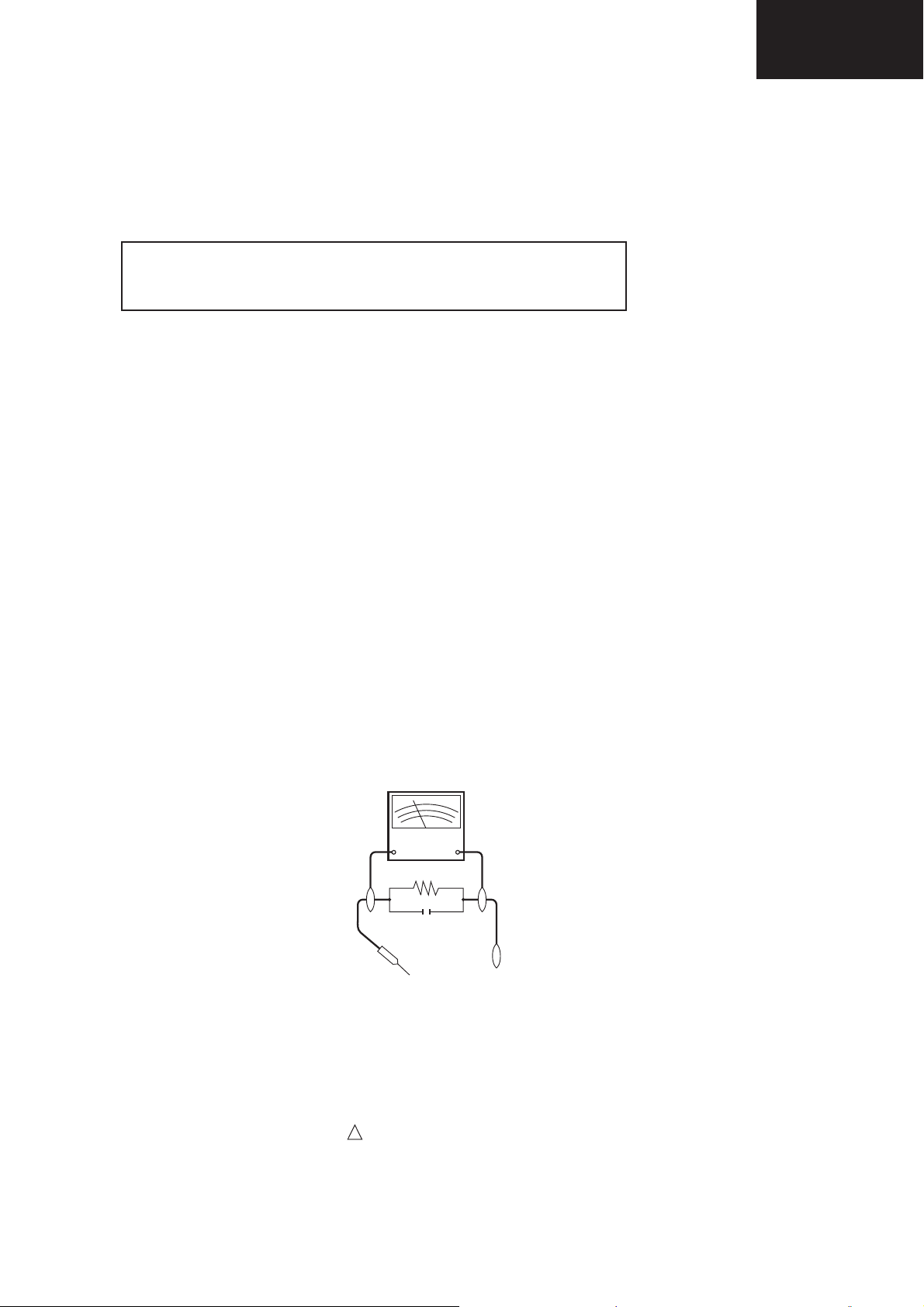
3. To be sure that no shock hazard exists, check for leakage current in the following manner.
•Plug the AC cord directly into a 220~240 volt AC outlet. (Do not use an isolation transformer for this test).
•Using two clip leads, connect a 1.5k ohm, 10 watt resistor paralleled by a 0.15μF capacitor in series with all exposed metal
cabinet parts and a known earth ground, such as electrical conduit or electrical ground connected to an earth ground.
•A true RMS reading multimeter should be used for this test, especially where the equipment uses a switch mode
power supply which may result in very non-sinusoidal leakage current.
•Connect the resistor connection to all exposed metal parts having a return to the chassis (antenna, metal cabinet,
screw heads, knobs and control shafts, escutcheon, etc.) and measure the AC voltage drop across the resistor.
All checks must be repeated with the AC cord plug connection reversed. (If necessary, a nonpolarized adaptor plug must
be used only for the purpose of completing these checks.)
Any reading of 1.05V peak (this corresponds to 0.7 mA. peak AC.) or more is excessive and indicates a potential shock
hazard which must be corrected before returning the monitor to the owner.
DVM
AC SCALE
1.5k ohm
10W
0.15 μF
TEST PROBE
TO EXPOSED
METAL PARTS
CONNECT TO
KNOWN EARTH
GROUND
SAFETY NOTICE
Many electrical and mechanical parts in LCD television have special safety-related characteristics.
These characteristics are often not evident from visual inspection, nor can protection afforded by them be necessarily
increased by using replacement components rated for higher voltage, wattage, etc.
Replacement parts which have these special safety characteristics are identifi ed in this manual; electrical components
having such features are identifi ed by “ “.
!
For continued protection, replacement parts must be identical to those used in the original circuit.
The use of a substitute replacement parts which do not have the same safety characteristics as the factory recommended
replacement parts shown in this service manual, may create shock, fi re or other hazards.
3
Page 4

LC-24LE210EH
PRECAUTIONS FOR USING LEAD-FREE SOLDER
1 Employing lead-free solder
“ALL PWB” of this model employs lead-free solder. The LF symbol indicates lead-free solder, and is attached on the
PWBs and service manuals. The alphabetical character following LF shows the type of lead-free solder.
Example:
L Fa
Indicates lead-free solder of tin, silver and copper.
L F n
Sn-Ag-Ni
Indicates lead-free solder of tin, silver and nickel.
2 Using lead-free wire solder
When fi xing the PWB soldered with the lead-free solder, apply lead-free wire solder. Repairing with conventional lead
wire solder may cause damage or accident due to cracks.
As the melting point of lead-free solder (Sn-Ag-Cu) is higher than the lead wire solder by 40°C, we recommend you to
use a dedicated soldering bit, if you are not familiar with how to obtain lead-free wire solder or soldering bit, contact our
service station or service branch in your area.
3 Soldering
As the melting point of lead-free solder (Sn-Ag-Cu) is about 220°C which is higher than the conventional lead solder by
40°C, and as it has poor solder wettability, you may be apt to keep the soldering bit in contact with the PWB for extended
period of time. However, Since the land may be peeled off or the maximum heat-resistance temperature of parts may be
exceeded, remove the bit from the PWB as soon as you confi rm the steady soldering condition.
Lead-free solder contains more tin, and the end of the soldering bit may be easily corroded. Make sure to turn on and
off the power of the bit as required.
If a different type of solder stays on the tip of the soldering bit, it is alloyed with lead-free solder. Clean the bit after every
use of it.
When the tip of the soldering bit is blackened during use, fi le it with steel wool or fi ne sandpaper.
Be careful when replacing parts with polarity indication on the PWB silk.
Lead-free wire solder for servicing.
4
Page 5

END OF LIFE DISPOSAL
A. Information on Disposal for Users (private households)
1. In the European Union
Attention: If you want to dispose of this equipment, please do not use the ordinary dust bin!
Used electrical and electronic equipment must be treated separately and in accordance with legislation that requires
proper treatment, recovery and recycling of used electrical and electronic equipment.
Following the implementation by member states, private households within the EU states may return their used
Attention: Your product
is marked with this
symbol. It means that
used electrical and
electronic products
should not be mixed
with general household
waste. There is a
separate collection
system for these
products.
electrical and electronic equipment to designated collection facilities free of charge*. In some countries* your local
retailer may also take back your old product free of charge if you purchase a similar new one.
*) Please contact your local authority for further details.
If your used electrical or electronic equipment has batteries or accumulators, please dispose of these separately
beforehand according to local requirements.
By disposing of this product correctly you will help ensure that the waste undergoes the necessary treatment, recovery
and recycling and thus prevent potential negative effects on the environment and human health which could otherwise
arise due to inappropriate waste handling.
2. In other Countries outside the EU
LC-24LE210EH
If you wish to discard this product, please contact your local authorities and ask for the correct method of disposal.
For Switzerland: Used electrical or electronic equipment can be returned free of charge to the dealer, even if you don’t
purchase a new product. Further collection facilities are listed on the homepage of www.swico.ch or www.sens.ch.
B. Information on Disposal for Business Users
1. In the European Union
If the product is used for business purposes and you want to discard it:
Please contact your SHARP dealer who will inform you about the take-back of the product. You might be charged for
the costs arising from take-back and recycling. Small products (and small amounts) might be taken back by your local
collection facilities.
For Spain: Please contact the established collection system or your local authority for take-back of your used
products.
2. In other Countries outside the EU
If you wish to discard of this product, please contact your local authorities and ask for the correct method of disposal.
The battery supplied with this product contains traces of Lead.
For EU: The crossed-out wheeled bin implies that used batteries should not be put to the general household waste!
There is a separate collection system for used batteries, to allow proper treatment and recycling in accordance with
legislation. Please contact your local authority for details on the collection and recycling schemes.
For Switzerland: The used battery is to be returned to the selling point.
For other non-EU countries: Please contact your local authority for correct method of disposal of the used battery.
5
Page 6

LC-24LE210EH
SERVICE ADJUSTMENTS
2. Entering and exiting the adjustment process mode. Exclusive method for this Hotel mode.
1. Entering / exiting the adjustment process mode manually.
0. Connect a HDMI source through “HDMI 1” terminal (through “HDMI 2” does not work.) and switch it on.
1. Once the TV is on, unplug the AC power cord.
2. Press and hold “V+” and “b” keys, simultaneously, and then plug the AC power cord.
3. A password will be requested. Introduce “0027”.
4. “PUBLIC MODE” menu appears on the screen.
5. Press cursor ▼/▲ until selecting “HOTEL MODE”, then set it to OFF.
6. Press cursor ▼ until selecting “EXECUTE”, then press OK.
7. Switch OFF and ON the TV set.
8. Now the TV is in normal standard operation, all the features are available and it may be serviced without any
external signal device.
2. Once the TV has been serviced, activate again the Hotel mode by restoring the factory default
values.
1. Press the MENU key.
2. Press cursor ▼/▲ until selecting “OPTION” submenu.
3. Press cursor ▼/▲ until selecting “RESTORE FACTORY DEFAULT” and confi rm selecting “YES”.
4. Description of display
Figure 1: Main Service Adjustment Menu
SHARP FACTORY MENU
Main version 24LE210EHE SHARP v1.0 SEES v96 MSTAR CL322528
Bootloader version BD_MST064E_C01A 2
Normal standby cause Remote control
Error standby cause None
INIT
ADJUST
ETC
PUBLIC MODE
SMARTLOADER
ADC ADJUST
GAMMA
SYSTEM INFORMATION
(2) (3)
(1)
← Informative (Main microprocessor version).
← Informative.
← Informative (Remote Control/Keyboard…).
← Informative (None/Lamp Error).
← Press “OK” to go to INIT submenu.
← Press “OK” to go to ADJUST submenu.
← Press “OK” to go to ETC submenu.
← Press “OK” to go to PUBLIC MODE submenu.
← Press “OK” to go to SMARTLOADER submenu.
← Press “OK” to go to ADC ADJUST submenu.
← Press “OK” to go to GAMMA submenu.
← Press “OK” to go to SYSTEM INFORMATION submenu.
No. Description Display specifi cation
(1) Service Information Current Software version and others.
(2) Item name Submenus to be checked or adjusted (by pressing “OK” button)
(3) Factory init and Inch setting Are shown on INIT submenu
6
Page 7

REF No
PARTS
DESCRIPTION
PARTS LISTING
REPLACEMENT PARTS
Replacement parts which have special safety characteristics are identifi ed in this manual.
Electrical components having such features are identifi ed by in the Replacement Parts Listing.
The use of a substitute replacement part which does not have the same safety characteristics as the factory recommended is
not permitted.
Replacement parts not shown in this service manual may create shock fi re, or other hazards.
HOW TO ORDER REPLACEMENT PARTS
To have your order completed promptly and correctly please supply the following information.
1. MODEL NUMBER 2. REF. NO. 3. PART NO.
4. DESCRIPTION 5. CODE 6. QUANTITY
MARK *: SPARE PARTS DELIVERY SECTION
SN CODE EX CODE
.
LC-24LE210EH PRINTED WIRING BOARDS
DSETUF639WE11 MAIN/LED UNIT LC24LE210EH S -- --
LC-24LE210EH ACCESSORIES
DLAB-D871WE01 LABELS SET LC24LE210EH S -- --
*
BW BF
LC-24LE210EH
7
Page 8

LC-24LE210EH
SHARP CORPORATION
AV System Group
COPYRIGHT © 2011 BY SHARP CORPORATION
ALL RIGHTS RESERVED
No part of this publication may be reproduced,
stored in a retrieval system, or transmitted in any
form or by any means, electronic, mechanical,
photocopying, recording, or otherwise, without
prior written permission of the publisher.
SHARP ELECTRONICA ESPAÑA S.A.
Service Manual Group
Engineering Dept.
C/ Sena, 2-10
08174 Sant Cugat del Vallès
Barcelona
Spain
8
 Loading...