

Page 1
Revised Edition
LCD COLOR TELEVISION
LC-19SK25U
LC-19SK25U-W
LC-19SB25U
LC-19SB25U-W
LC-19SB15U
N38B2LC19K25U
MODEL
In the interests of user-safety (Required by safety regulations in some countries) the set should be restored to its original condition and only parts identical to those specified should be used.
The revised edition added the schematic of SUB3(sound) after Page 81.
CONTENTS
ネ
IMPORTANT SERVICE SAFETY PRECAUTION ..........................................................................................2
ネ
SPECIFICATIONS .........................................................................................................................................5
ネ
OPERATION MANUAL ..................................................................................................................................7
ネ
DIMENSIONS ..............................................................................................................................................11
ネ
REMOVING OF MAJOR PARTS .................................................................................................................13
ネ
ADJUSTING PROCEDURE OF EACH SECTION ......................................................................................18
ネ
PUBLIC MODE SETTING PROCEDURE ...................................................................................................40
ネ
TROUBLESHOOTING TABLE ..................................................................................................................... 45
ネ
MAJOR IC INFORMATIONS ....................................................................................................................... 53
ネ
BLOCK DIAGRAM .......................................................................................................................................54
ネ
OVERALL WIRING DIAGRAM .................................................................................................................... 56
ネ
DESCRIPTION OF SCHEMATIC DIAGRAM ..............................................................................................58
ネ
SCHEMATIC DIAGRAM
RC/LED Unit ..............................................................................................................................................59
MAIN Unit ..................................................................................................................................................60
SUB Unit .................................................................................................................................................... 78
POWER_INVERTER Unit ..........................................................................................................................84
KEY Unit ....................................................................................................................................................86
ネ
PRINTED WIRING BOARD ASSEMBLIES .................................................................................................87
ネ
REPLACEMENT PARTS LIST ...................................................................................................................105
ネ
PACKING OF THE SET ............................................................................................................................. 124
LC-19D45U
Page
This document has been published to be used for
after sales service only.
The contents are subject to change without notice.
Page 2
2
LC-19SK25U/U-W
LC-19SB25U/U-W
LC-19SB15U
LC-19D45U
A V
DVM
AC SCALE
1.5k ohm
10W
TO EXPOSED
METAL PARTS
CONNECT TO
KNOWN EARTH
GROUND
0.15 µF
TEST PROBE
IMPORTANT SERVICE SAFETY PRECAUTION
Service work should be performed only by qualified service technicians who are thoroughly familiar with all safety checks and the servicing guidelines which follow:
WARNING
1. For continued safety, no modification of any circuit
should be attempted.
2. Disconnect AC power before servicing.
C A U T I O N: F O R C O N T I N U E D
PROTECTION AGAINST A RISK OF
FIRE REPLACE ONLY WITH SAME
TYPE F7502 (2.5A, 250V) FUSE.
BEFORE RETURNING THE RECEIVER
(Fire & Shock Hazard)
Before returning the receiver to the user, perform
the following safety checks:
1. Inspect all lead dress to make certain that leads are
not pinched, and check that hardware is not lodged
between the chassis and other metal parts in the
receiver.
2. Inspect all protective devices such as non-metallic
control knobs, insulation materials, cabinet backs,
adjustment and compartment covers or shields,
isolation resistor-capacitor networks, mechanical
insulators, etc.
3. To be sure that no shock hazard exists, check for
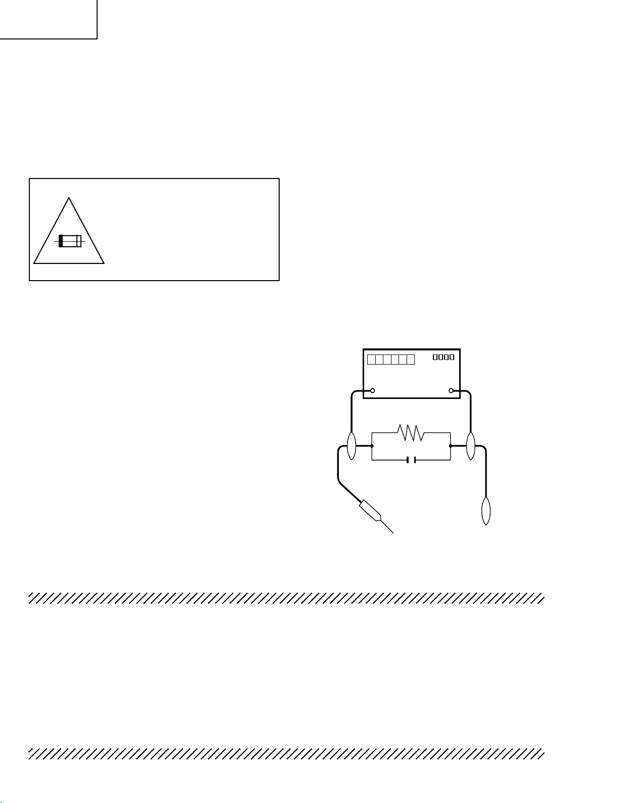
leakage current in the following manner.
Plug the AC cord directly into a 120 volt AC outlet,
•
and connect the DC power cable into the receiver's
DC jack. (Do not use an isolation transformer for this
test).
Using two clip leads, connect a 1.5k ohm, 10 watt
•
resistor paralleled by a 0.15µF capacitor in series
with all exposed metal cabinet parts and a known
earth ground, such as electrical conduit or electrical
ground connected to an earth ground.
Use an AC voltmeter having with 5000 ohm per volt,
•
or higher, sensitivity or measure the AC voltage drop
across the resistor.
Connect the resistor connection to all exposed metal
•
parts having a return to the chassis (antenna, metal
cabinet, screw heads, knobs and control shafts,
escutcheon, etc.) and measure the AC voltage drop
across the resistor.
All checks must be repeated with the AC cord plug
connection reversed. (If necessary, a nonpolarized
adaptor plug must be used only for the purpose of
completing these checks.)
Any reading of 0.75V peak (this corresponds to 0.5
mA. peak AC.) or more is excessive and indicates
a potential shock hazard which must be corrected
before returning the monitor to the owner.
SAFETY NOTICE
Many electrical and mechanical parts in LCD television
have special safety-related characteristics.
Thes e c haracter istic s are often n o t eviden t from
visu a l inspecti o n , nor can p r o tection a fford e d by
them be necessarily increased by using replacement
components rated for higher voltage, wattage, etc.
Replacement parts which have these special safety
characteristics are identified in this manual; electrical
components having such features are identified by "!"
and shaded areas in the Replacement Parts Lists and
Schematic Diagrams.
For continued protection, replacement parts must be
identical to those used in the original circuit.
The use of substitute replacement parts which do not
have the same safety characteristics as the factory
recommended replacement parts shown in this service
manual, may create shock, fire or other hazards.
Page 3
LC-19SK25U/U-W
A V
DVM
AC SCALE
1.5k ohm
10W
TO EXPOSED
METAL PARTS
CONNECT TO
KNOWN EARTH
GROUND
0.15 µF
TEST PROBE
LC-19SB25U/U-W
LC-19SB15U
LC-19D45U
PRECAUTIONS A PRENDRE LORS DE LA REPARATION
La réparation ne peut être effectuée que par un technicien spécialisé qui s'est
parfaitement accoutumé à toute vérification de sécurité et aux conseils suivants.
AVERTISSEMENT
1. Pour la sécurité continue, n'entreprendre aucune
modification de tout circuit.
2. Débrancher l'alimentation CA avant la réparation.
PRECAUTION: POUR LA
PROTECTION CONTINUE
CONTRE LES RISQUES
D'INCENDIE, REMPLACER LE
FUSIBLE PAR UN FUSIBLE DE
MEME TYPE F7502 (2.5A, 250V).
AVANT DE RENDRE LE RECEPTEUR A L’UTILISATEUR (Incendie et choc électrique)
Avant de rendre le récepteur à l'utilisateur, effectuer
les vérifications suivantes.
1. Inspecter tous les faisceaux de câbles pour s'assurer
que les fils ne soient pas pincés ou qu'un outil ne
soit pas placé entre le châssis et les autres pièces
métalliques du récepteur.
2. Inspecter tous les dispositifs de protection comme
le s bo u t on s d e co m m an d e n o n- m é ta l l iq u es,
les isolants, le dos du coffret, les couvercles ou
bl i n dages de réglag e e t d e c ompar t iment, les
rés eaux de rési stanc e-capa cité, les iso lateu rs
mécaniques, etc.
3. S'assurer qu'il n'y ait pas de danger d'électrocution
en vérifiant la fuite de courant, de la facon suivante:
Brancher le cordon d'alimentation directem-ent à
•
une prise de courant de 120V. (Ne pas utiliser de
transformateur d'isolation pour cet essai).
A l ' ai d e d e de u x f i l s à pi n c es, br a nc h e r u ne
•
résistance de 1.5kΩ 10 watts en parallèle avec un
condensateur de 0.15µF en série avec toutes les
pièces métalliques exposées du coffret et une terre
connue comme une conduite électrique ou une prise
de terre branchée à la terre.
Utiliser un voltmètre CA d'une sensibilité d'au moins
•
5000Ω/V pour mesurer la chute de tension CA en
travers de la résistance.
Toucher avec la sonde d'essai les pièces métalliques
•
expo sées qui prés entent une voie de retour au
châssis (antenne, coffret métallique, tête des vis,
arbres de commande e t des boutons, écusson,
etc.) et mesurer la chute de tension CA en travers
de la résistance. Toutes les vérifications doivent
être refaites après avoir inversé la fiche du cordon
d'alimentation. (Si nécessaire, une prise d'adpatation
non p olarisée d oit être u t ilisée d ans le but de
terminer ces vérifications.)
La tension de pointe mesurèe ne doit pas dépasser
0.75V (correspondante au courant CA de pointe de
0.5mA). Dans le cas contraire, il y a une possibilité
de choc électrique qui doit être supprimée avant de
rendre le récepteur au client.
AVIS POUR LA SECURITE
De nombreuses pièces, éle ctr iques et mécaniques,
dans les téléviseurs de l'afficharge à cristaux liquides
présentent des caractéristiques spéciales relatives à la
sécurité.
Ces caracténstiques ne sont souvent pas évidentes
à vu e. L e d e g r é d e pr o t e c t io n n e p eu t p a s être
nécessairement augmentée en utilisant des pièces de
remplacement étalonnées pour haute tension, puissance,
etc.
Les p i èces de re m p lace m e n t q u i prés e n t ent c e s
caractéristiques sont identifiées dans ce manuel; les
pièces électriques qui présentent ces particularités sont
identifiées par la marque "!" et hachurées dans la
liste des pièces de remplacement et les diagrammes
schématiques.
Pour assurer la pr otec tion, ces pièc es do ivent ê tre
identiques à celles utilisées dans le circuit d'origine.
L' u t il i sa t i o n de pi è ce s q u i n ' on t p a s l e s mê m e s
caractér istiques que les piè ces recommandées par
l'usine, indiquées dans ce manuel, peut provoquer des
électrocutions, incendies ou autres accidents.
3
Page 4
4
LC-19SK25U/U-W
LC-19SB25U/U-W
LC-19SB15U
LC-19D45U
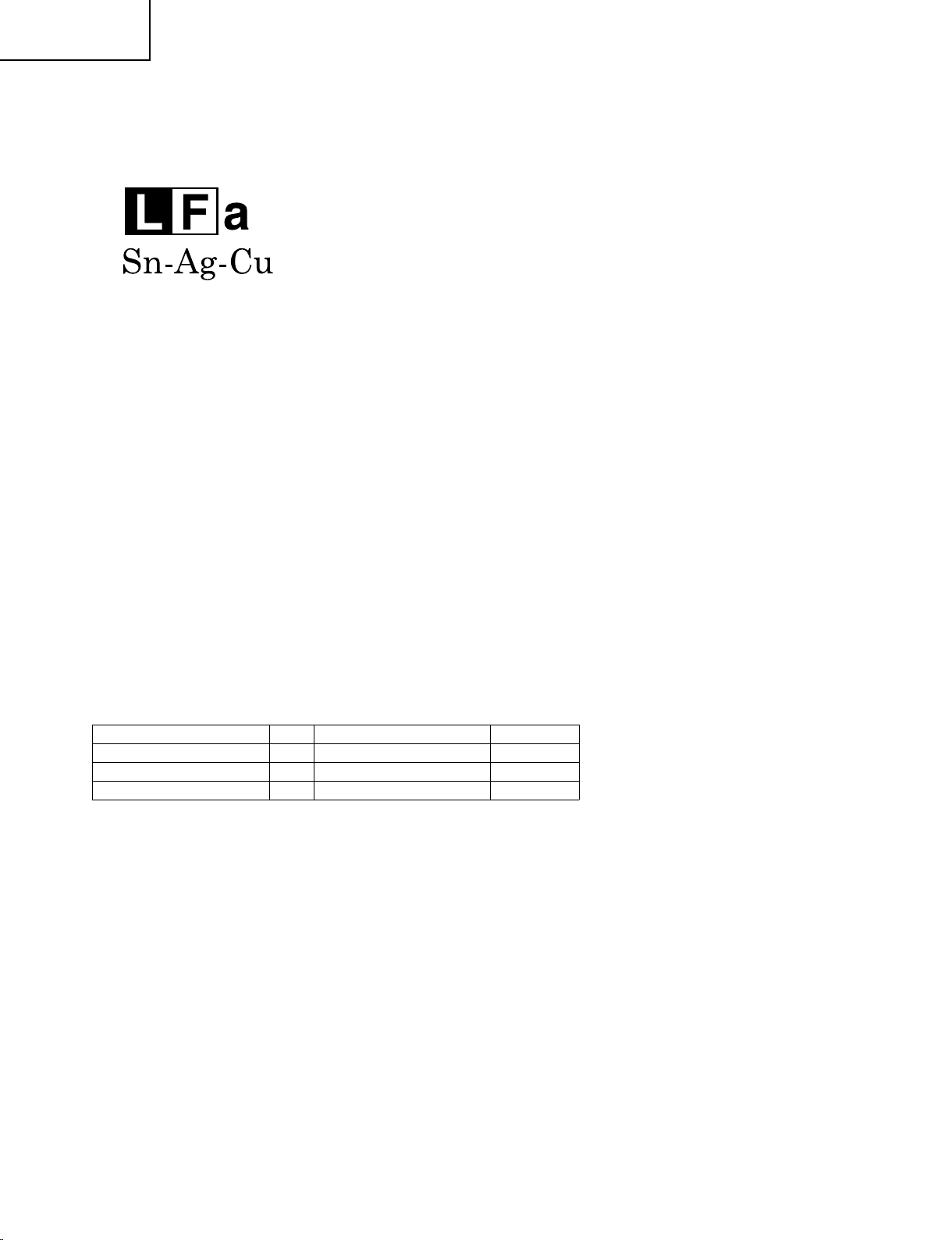
Precautions for using lead-free solder
1 Employing lead-free solder
"All PWBs" of this model employs lead-free solder. The LF symbol indicates lead-free solder, and is attached on
the PWBs and service manuals. The alphabetical character following LF shows the type of lead-free solder.
Example:
Indicates lead-free solder of tin, silver and copper.
2 Using lead-free wire solder
When fixing the PWB soldered with the lead-free solder, apply lead-free wire solder. Repairing with conventional
lead wire solder may cause damage or accident due to cracks.
As the melting point of lead-free solder (Sn-Ag-Cu) is higher than the lead wire solder by 40°C, we recommend
you to use a dedicated soldering bit, if you are not familiar with how to obtain lead-free wire solder or soldering
bit, contact our service station or service branch in your area.
3 Soldering
As the melting point of lead-free solder (Sn-Ag-Cu) is about 220°C which is higher than the conventional lead
solder by 40°C, and as it has poor solder wettability, you may be apt to keep the soldering bit in contact with the
PWB for extended period of time. However, Since the land may be peeled off or the maximum heat-resistance
temperature of parts may be exceeded, remove the bit from the PWB as soon as you confirm the steady
soldering condition.
Lead-free solder contains more tin, and the end of the soldering bit may be easily corroded. Make sure to turn
on and off the power of the bit as required.
If a different type of solder stays on the tip of the soldering bit, it is alloyed with lead-free solder. Clean the bit
after every use of it.
When the tip of the soldering bit is blackened during use, file it with steel wool or fine sandpaper.
Be careful when replacing parts with polarity indication on the PWB silk.
Lead-free wire solder for servicing
Part No,
ZHNDAi123250E J
ZHNDAi126500E J
ZHNDAi12801KE J
Description Code
★
0.3mm 250g(1roll) BL
φ
0.6mm 500g(1roll) BK
φ
1.0mm 1kg(1roll) BM
φ
Page 5
SPECIFICATIONS
LC-19SK25U/U-W
LC-19SB25U/U-W
LC-19SB15U
LC-19D45U
Item
LCD panel
Resolution
TV
Function
TV-standard (CCIR)
Receiving
Channel
Audio multiplex
Audio out
Terminals
INPUT 1
INPUT 2
INPUT 3
INPUT 4
Headphone
ANTENNA
DIGITAL AUDIO OUTPUT
OSD language
Power Requirement
Power Consumption
VHF/UHF
CATV(analog)
Digital Terrestrial
Broadcast (8VSB)
Digital Cable
*1
(64/256 QAM)
Model: LC-19SK25U/LC-19SK25U-W/LC-19SB25U/LC-19SB25U-W/LC-19SB15U
18.5o screen size class Advanced Super View & BLACK TFT LCD
( Diagonal Measurement: 181/
1,049,088 pixels (1,366
g
768)
)
o
2
American TV Standard ATSC/NTSC System
VHF 2-13ch, UHF 14-69ch
1-135ch (STD, HRC, IRC)
2-69ch
1-135ch
BTSC System
2W
2
g
COMPONENT in
AV in, S-VIDEO in
HDMI in with HDCP(480P, 720P/60Hz, 1080I/60Hz, VGA), HDMI Analog Audio in
15 pin mini D-sub female connector, PC Audio in (Ø 3.5 mm jack)
Ø 3.5 mm jack (Audio Output)
Unbalance, F Type g 1 for Analog (VHF/UHF/CATV) and Digital (AIR/CABLE)
75
q
Optical Digital audio output
1 (Dolby Digital)
g
English/French/Spanish
AC 120 V, 60 Hz
44 W (0.5 W Standby with AC 120V)
Weight
TV + stand
TV only
Dimension
*2
(W g H g D)
TV + stand
TV only
Operating temperature
*1
Emergency alert messages via Cable are unreceivable.
*2
The dimensional drawings are shown on the inside back cover.
11.4 lbs./5.2 kg
10.3 lbs./4.7 kg
3
18
3
18
32°F to e104°F (0°C to e40°C)
e
11
/16
14
g
/64
63
/64 inch
7
g
/16 g 12 19/32 g 2 61/64 inch
• As part of policy of continuous improvement, SHARP reserves the right to make design and specification changes for product
improvement without prior notice. The performance specification figures indicated are nominal values of production units.
There may be some deviations from these values in individual units.
5
Page 6
6
LC-19SK25U/U-W
LC-19SB25U/U-W
LC-19SB15U
LC-19D45U
SPECIFICATIONS(Continued)
Item
LCD panel
Resolution
TV
Function
TV-standard (CCIR)
Receiving
Channel
Audio multiplex
Audio out
Terminals
INPUT 1
INPUT 2
INPUT 3
INPUT 4
Headphone
ANTENNA
DIGITAL AUDIO OUTPUT
OSD language
Power Requirement
Power Consumption
VHF/UHF
CATV(analog)
Digital Terrestrial
Broadcast (8VSB)
Digital Cable
*1
(64/256 QAM)
Model: LC-19D45U
18.5o screen size class Advanced Super View & BLACK TFT LCD
( Diagonal Measurement: 181/
1,049,088 pixels (1,366
g
768)
)
o
2
American TV Standard ATSC/NTSC System
VHF 2-13ch, UHF 14-69ch
1-135ch (STD, HRC, IRC)
2-69ch
1-135ch
BTSC System
2
2W
g
COMPONENT in
AV in, S-VIDEO in
HDMI in with HDCP(480P, 720P/60Hz, 1080I/60Hz, VGA), HDMI Analog Audio in
15 pin mini D-sub female connector, PC Audio in (Ø 3.5 mm jack)
Ø 3.5 mm jack (Audio Output)
Unbalance, F Type g 1 for Analog (VHF/UHF/CATV) and Digital (AIR/CABLE)
75
q
Optical Digital audio output
1 (Dolby Digital)
g
English/French/Spanish
AC 120 V, 60 Hz
44 W (0.5 W Standby with AC 120V)
Weight
TV + stand
TV only
Dimension
(W
H g D)
g
*2
TV + stand
TV only
Operating temperature
*1
Emergency alert messages via Cable are unreceivable.
*2
The dimensional drawings are shown on the inside back cover.
11.9 lbs./5.4 kg
10.1 lbs./4.5 kg
3
18
/16 g 14 11/64 g 7 63/64 inch
3
/16 g 12 19/32 g 3 1/32 inch
18
32°F to e104°F (0°C to e40°C)
e
• As part of policy of continuous improvement, SHARP reserves the right to make design and specification changes for product
improvement without prior notice. The performance specification figures indicated are nominal values of production units.
There may be some deviations from these values in individual units.
Page 7
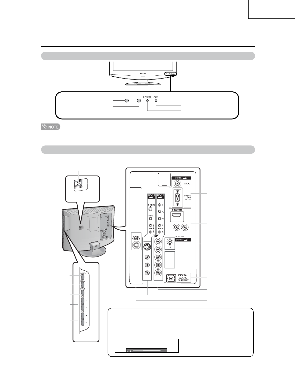
Part names
20
TV (Front)
LC-19SK25U/U-W
LC-19SB25U/U-W
LC-19SB15U
LC-19D45U
OPERATION MANUAL
Remote control sensor
*OPC: Optical Picture Control
TV (Side/Rear)
AC INPUT
terminal
OPC sensor*
OPC indicator
POWER indicator
INPUT 4 terminals
(PC IN)
INPUT 3 terminals
(HDMI)
POWER
button
MENU
button
INPUT
button
Channel
buttons
(CHr/
Volume
buttons
(VOLk/l)
s
HEADPHONE terminal
DIGITAL AUDIO OUTPUT
terminal
INPUT 1 terminals
INPUT 2 terminals
Antenna/Cable in
)
Regarding the headphone jack
• Use headphones with a stereo mini plug (Ø 3.5 mm).
• Be sure to unplug headphones from the jack when they are not in use.
• The speakers do not output volume when headphones are plugged in.
• You can set the volume to different levels for each input source.
Volume display when
headphones are plugged in
7
Page 8
8
LC-19SK25U/U-W
LC-19SB25U/U-W
LC-19SB15U
LC-19D45U
Part names
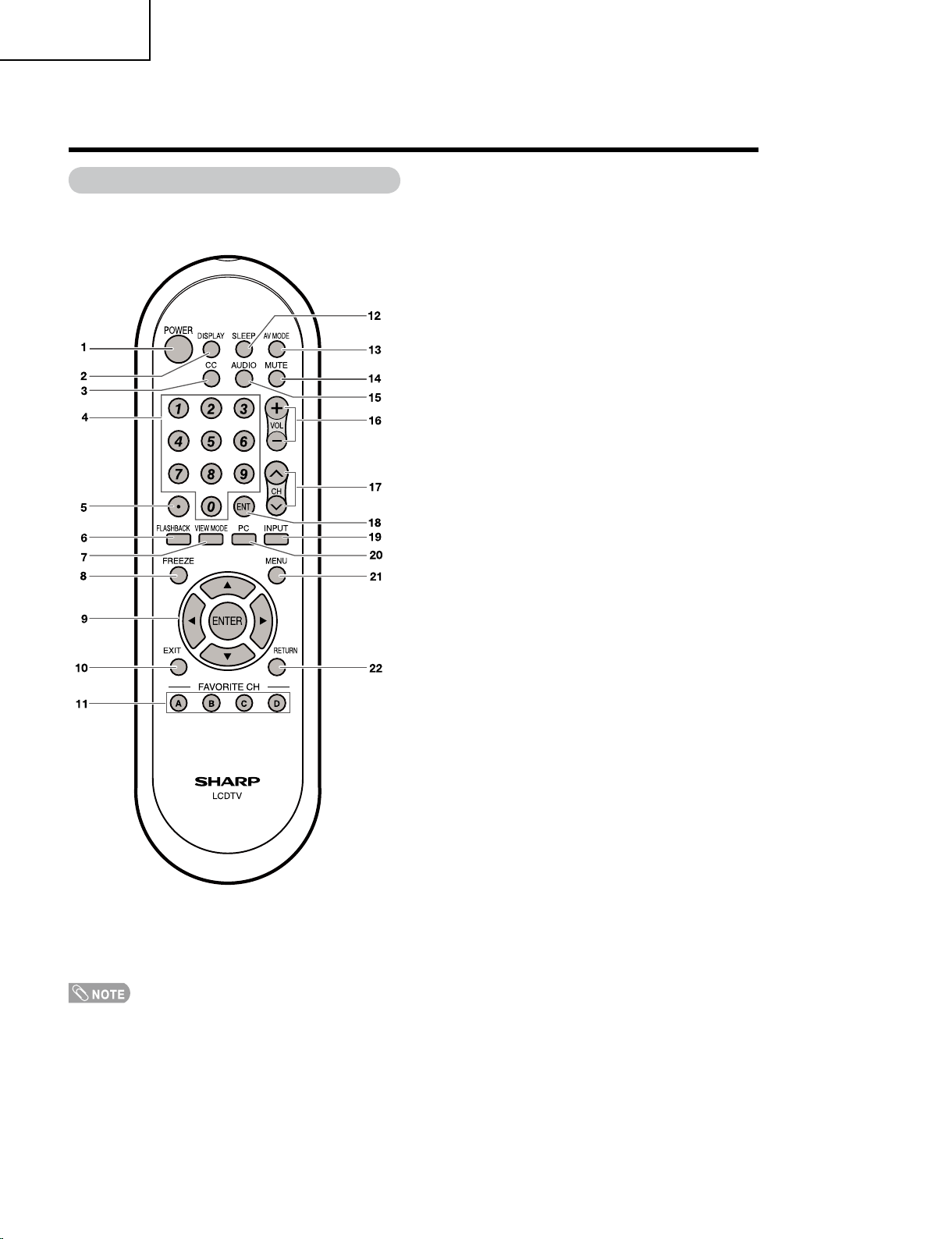
Remote control unit
1 POWER: Switch the TV power on or enters standby.
2 DISPLAY: Display the channel information.
3 CC: Display captions from a closed-caption source.
4 0 – 9: Set the channel.
5 • (DOT)
6 FLASHBACK: Return to the previous channel or
external input mode.
7 VIEW MODE: Select the screen size.
8 FREEZE: Set the still image. Press again to return to
normal screen.
9 a/b/c/d/ENTER: Select a desired item on the
screen.
10 EXIT: Turn off the menu screen.
11 FAVORITE CH
A, B, C, D: Select 4 preset favorite channels in 4
different categories.
While watching, you can toggle the selected channels
by pressing A, B, C and D.
12 SLEEP: Set the sleep timer.
13 AV MODE: Select an audio or video setting. (When
the input source is TV, INPUT 1 or 2: STANDARD,
MOVIE, GAME, USER, DYNAMIC (Fixed), DYNAMIC.
When the input source is INPUT 3: STANDARD,
MOVIE, GAME, PC, USER, DYNAMIC (Fixed),
DYNAMIC. When the input source is INPUT 4:
STANDARD, PC, USER)
14 MUTE: Mute the sound.
15 AUDIO: Selects the MTS/SAP or the audio mode
during multi-channel audio broadcasts.
16 VOL k/l: Set the volume.
17 CHr/s: Select the channel.
18 ENT: Jumps to a channel after selecting with the 0–9
buttons.
19 INPUT: Select a TV input source. (TV, INPUT 1,
INPUT 2, INPUT 3, INPUT 4)
20 PC: Quickly access to PC mode.
21 MENU: Display the menu screen.
22 RETURN: Return to the previous menu screen.
• When using the remote control unit, point it at the TV.
Page 9
Part names
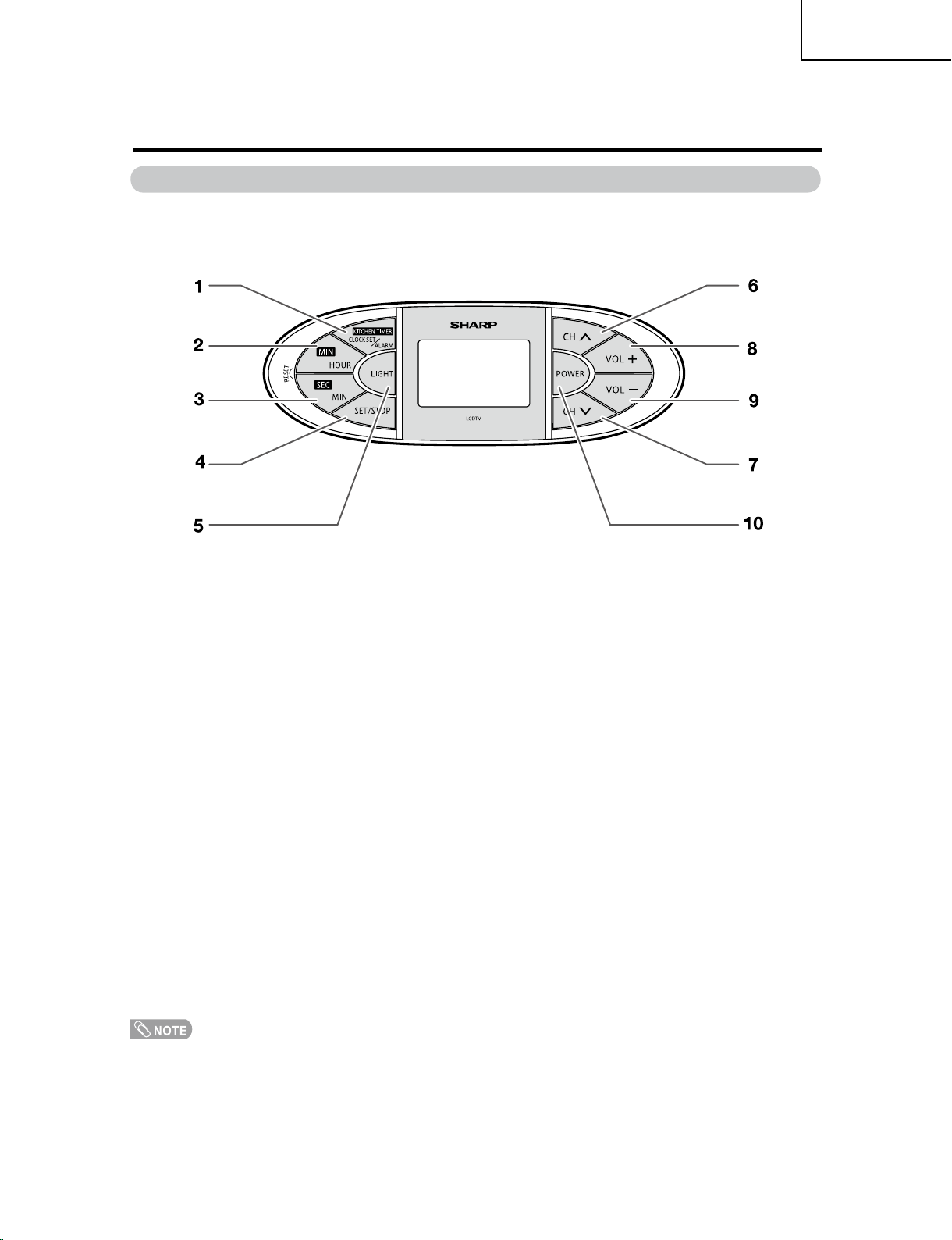
Kitchen Remote control unit (LC-19SK25U/LC-19SK25U-W/LC-19D45U)
LC-19SK25U/U-W
LC-19SB25U/U-W
LC-19SB15U
LC-19D45U
1 KITCHEN TIMER/CLOCK SET/ALARM:
Set the kitchen timer, clock or alarm.
2 MIN/HOUR :
Set the minute of kitchen timer and the hour of clolck or alarm.
3 SEC/MIN :
Set the second of kitchen timer and the minute of clock or alarm.
4 SET/STOP :
Confirm setting or stop beeper sound.
5 LIGHT :
Light on the remote control LCD backlight.
6,7 CHr/CHs :
Select the channel.
8 VOL+ :
To increase the volume.
9 VOL- :
To decrease the volume.
10 POWER :
Switch the TV power on or enters standby.
• The method of using the Kitchcen Remote control unit, please see page 50~52 of operation manual.
9
Page 10
10
LC-19SK25U/U-W
LC-19SB25U/U-W
LC-19SB15U
LC-19D45U
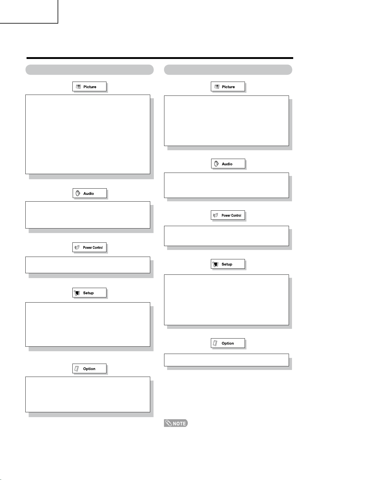
Basic adjustment settings
Menu items for TV/INPUT 1/2 Menu items for HDMI/PC-IN
OPC
Backlight
Contrast
Brightness
Color
Tint
Sharpness
Advanced
C.M.S
Color Temp.
Film Mode
3D-Y/C
Monochrome
I/P Setting
Reset
Treble
Bass
Balance
Reset
No Signal Off
No Operation Off
OPC
Backlight
Contrast
Brightness
Advanced
C.M.S
Color Temp.
Monochrome
Reset
Treble
Bass
Balance
Reset
No Signal Off
No Operation Off
Power Management
EZ Setup
CH Setup
Input Label
Parental CTRL
Position
Rotate
Language
Reset
DNR
Audio Only
Digital Audio
Color System
Digital Caption Setup
Favorite CH
Input Label
Parental CTRL
Position
PC Setup
HDMI Audio Select
HDMI Auto View
Rotate
Language
Reset
Audio Only
• Some menu items may not be displayed depending on the
selected input source.
Page 11
DIMENSIONS
10
(254)
18
3
/16
(462)
12
19
/32 (320)
1
37
/64 (40)
16
7
/32
(411.8)
9
5
/32
(232.4)
14
11
/64 (360)
8
37
/64 (218)
3
15
/16
(100)
3
15
/16
(100)
3
17
/64
(83)
7
63
/64 (203)
2
61
/64 (75)
2
61
/64
(75)
1
59
/64
(49)
LC-19SK25U/U-W
LC-19SB25U/U-W
LC-19SB15U
LC-19D45U
LC-19SK25U/LC-19SK25U-W/LC-19SB25U/LC-19SB25U-W/LC-19SB15U
Unit: inch (mm)
11
Page 12
12
LC-19SK25U/U-W
LC-19SB25U/U-W
LC-19SB15U
LC-19D45U
10
(254)
18
3
/16
(462)
12
19
/32 (320)
1
37
/64 (40)
16
7
/32 (411.8)
9
5
/32
(232.4)
14
11
/64 (360)
8
37
/64 (218)
3
15
/16
(100)
3
15
/16
(100)
3
17
/64 (83)
7
63
/64
(203)
2
53
/64
(72) 3
5
/8 (92)
2
3
/64
(51)
3
1
/32
(77)
LC-19D45U
DIMENSIONS(Continued)
Unit: inch (mm)
Page 13
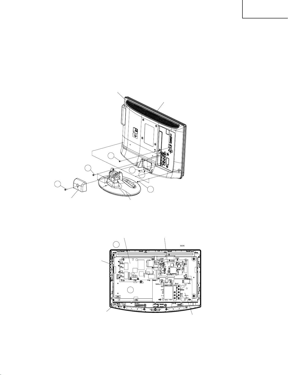
REMOVING OF MAJOR PARTS
Cabinet B
Cabinet A
3
3
3
2
1
4
Stand HINJI Cover
Stand
5
5
Inverter PWB
Main PWB
BTN PWB
LED PWB
(LC-19SK25U/LC-19SK25U-W)
1. Remove the Stand HINGI Cover fixing screw (1 pc.).
2. Remove the stand fixing screws (4 pcs.).
3. Remove the cabinet B fixing screws (10 pcs.).
4. Remove the cabinet B after opening from the direction of an arrow.
5. Disconnect all the connectors from all the PWBs.
LC-19SK25U/U-W
LC-19SB25U/U-W
LC-19SB15U
LC-19D45U
13
Page 14
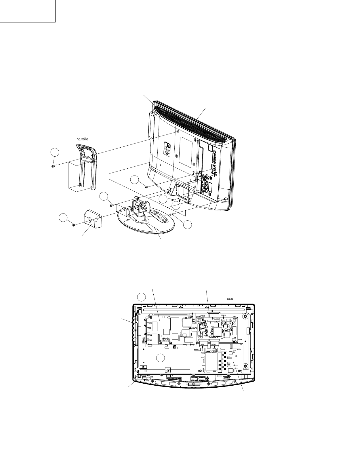
14
LC-19SK25U/U-W
LC-19SB25U/U-W
LC-19SB15U
LC-19D45U
Cabinet B
Cabinet A
3
2
1
3
3
4
Stand HINJI Cover
Stand
1
5
5
Inverter PWB
Main PWB
BTN PWB
LED PWB
Sub PWB
(LC-19D45U)
1. Remove the Stand HINGI Cover fixing screw (1 pc.) and the handle fixing screws (4 pcs).
2. Remove the stand fixing screws (4 pcs.).
3. Remove the cabinet B fixing screws (10 pcs.).
4. Remove the cabinet B after opening from the direction of an arrow.
5. Disconnect all the connectors from all the PWBs.
Page 15
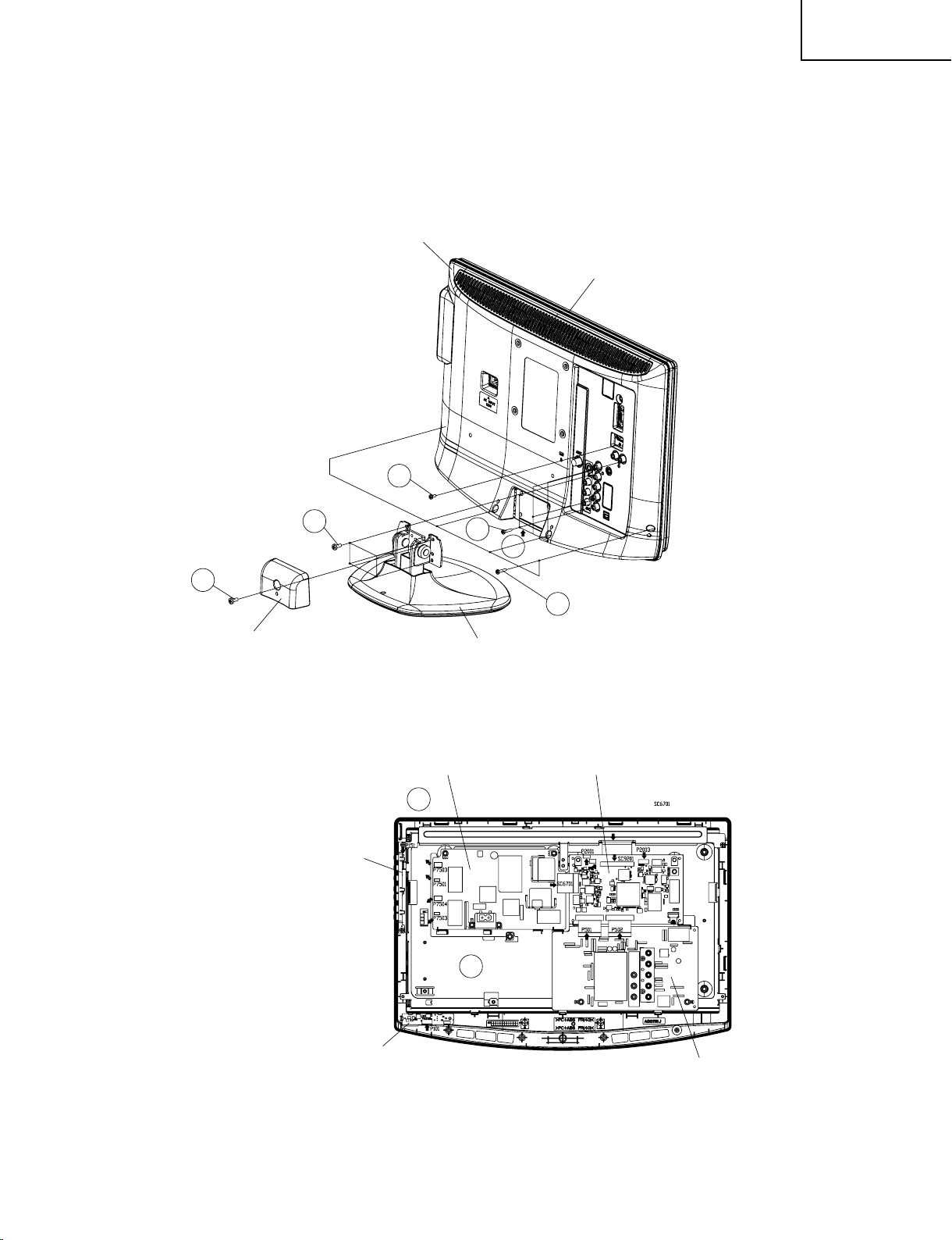
(LC-19SB25U/LC-19SB25U-W/LC-19SB15U)
Cabinet B
Cabinet A
3
2
1
5
5
3
3
4
Stand HINJI Cover
Stand
Inverter PWB
Main PWB
BTN PWB
LED PWB
Sub PWB
1. Remove the Stand HINGI Cover fixing screw (1 pc.).
2. Remove the stand fixing screws (4 pcs.).
3. Remove the cabinet B fixing screws (10 pcs.).
4. Remove the cabinet B after opening from the direction of an arrow.
5. Disconnect all the connectors from all the PWBs.
LC-19SK25U/U-W
LC-19SB25U/U-W
LC-19SB15U
LC-19D45U
15
Page 16
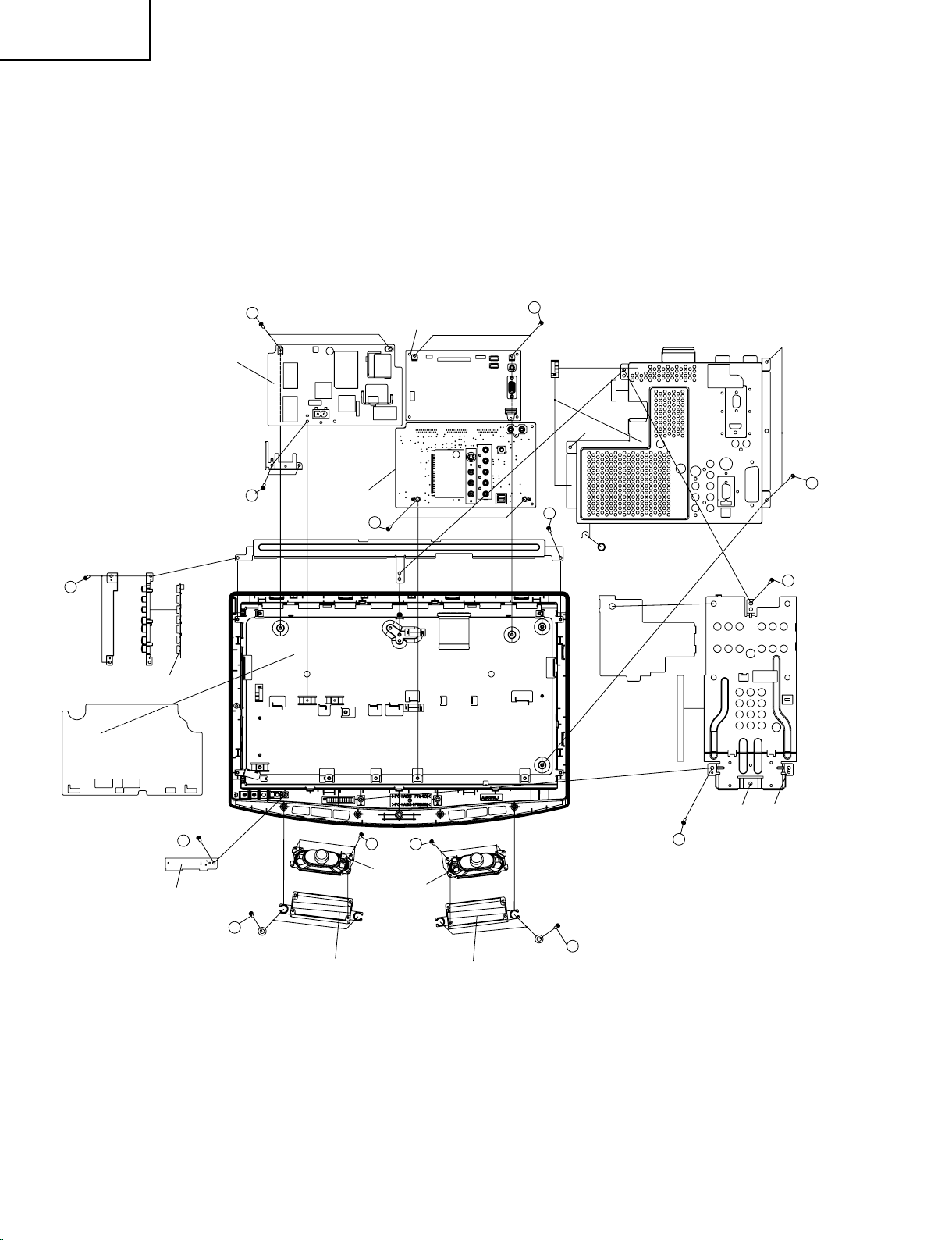
16
LC-19SK25U/U-W
LC-19SB25U/U-W
LC-19SB15U
LC-19D45U
Main PWB
Power PWB
Sub PWB
LED PWB
LED PWB
Speaker (L)
Speaker Angle (L)
Speaker Angle (R)
Speaker (R)
8
8
8
9
8
7
6
6
9
10
11
12
12
11
6. Remove the vesa angle fixing screws (4 pcs.).
7. Remove the 3 lock screws from Main Shield.
8. Remove the 9 lock screws from the sub PWB and main PWB and power PWB and AC angle. Detach the sub
PWB and main PWB and power PWB from LCD assembly.
9. Remove the 3 lock screws from the control button assembly and the source PWB Shield.
10. Remove the LED PWB fixing screws (1 pcs.).
11. Remove the 2 lock screws each from the right and left speakers ass’y and take out both the speakers ass’y.
12. Remove the 4 lock screws each from the right and left speaker angle.
Page 17
LC-19SK25U/U-W
5
5
Inverter PWB
Main PWB
BTN PWB
LED PWB
Sub PWB
LC-19SB25U/U-W
LC-19SB15U
LC-19D45U
Precautions in servicing the side-B (backside) of the main PWB unit
ネ
1. Remove the lock screws (2 pcs.) from the main PWB, detach the PWB from the set, and then turn it over.
2. Connect the service-specific extension cable (QCNW-E542WJZZ) between the main PWB (SC1201) and the
sub PWB (P501).
3. Connect the service-specific extension cable (QCNW-E542WJZZ) between the main PWB (SC1202) and the
sub PWB (P502).
4. Connect the service-specific extension cable (QCNW-D431WJZZ) between the main PWB (SC1204) and the
power PWB (SC7501).
5. Connect the service-specific extension cable (QCNW-C458WJQZ) between the main PWB (SC9201) and the
panel PWB (CN1).
Precautions in servicing the side-B (backside) of the power PWB unit
ネ
1. Remove the lock screws (4 pcs.) from the power PWB unit, detach the PWB from the set, and then turn it over.
2. Connect the service-specific extension cable (QCNW-D431WJZZ) between the power PWB (SC7501) and the
main PWB (SC1204).
Precautions in servicing the side-B (backside) of the sub PWB unit
ネ
1. Remove the lock screws (2 pcs.) from the sub PWB unit, detach the PWB from the set, and then turn it over.
2. Connect the service-specific extension cable (QCNW-E542WJZZ) between the sub PWB (P501) and the main
PWB (SC1201).
3. Connect the service-specific extension cable (QCNW-E542WJZZ) between the sub PWB (P502) and the main
PWB (SC1202).
Step Part No. Description
2 QCNW-E542WJZZ Extension Cable 23-pin Main (SC1201)-Sub (P501)
3 QCNW-E542WJZZ Extension Cable 23-pin Main (SC1202)-Sub (P502)
4 QCNW-D431WJZZ Extension Cable 15-pin Main (SC1204)-Power (SC7501)
5 QCNW-C458WJQZ Extension Cable 80-pin Main(SC9201)-Panel(CN1)
17
Page 18
18
LC-19SK25U/U-W
LC-19SB25U/U-W
LC-19SB15U
LC-19D45U
Main PWB P801
1 D5V TXD MPU 2
3 RESET MPU MODE MPU 4
5 RXD MPU M 32 TDI 6
7 BU3.3V M32 TDO 8
9 M 32 TRST M32 TCK 10
11 GND M32 TMS 12
13 ASEBRKAK_N ASEMDO 14
15 TRST_N TCK 16
17 TDI TDO 18
19 TMS RESET_N 20
EJ-Writer DTV
1 TCK GND/NC 8
2 TRST_N GND/ASEMD0 9
3 TDO GND 10
4 ASEBRKAK_N NC/3.3V 11
5 TMS GND 12
6 TDI GND 13
7 RESET_N GND 14
ADJUSTING PROCEDURE OF EACH SECTION
The adjustment values are set to the optimum conditions at the factory before shipping .If a value should become
improper or an adjustment is required due to part replacement, make an adjustment according to the following
procedure.
1. After replacement of the any PWB and/or IC for repair, please note the following
1.1
When replacing the unit DUNTKE352FM02, make sure to prepare the new unit loaded with updated software.
1.2 Special Equipment
1.2.1 Renesas E8A, the SUB microprocessor software Writer
1.2.2 Sophia systems DTV EJ-Writer, the Main software Writer
1.2.3 Convertor 1, please refer to following schematic and make one.
1.2.4 Convertor 2, please refer to following instruction and make one.
Page 19
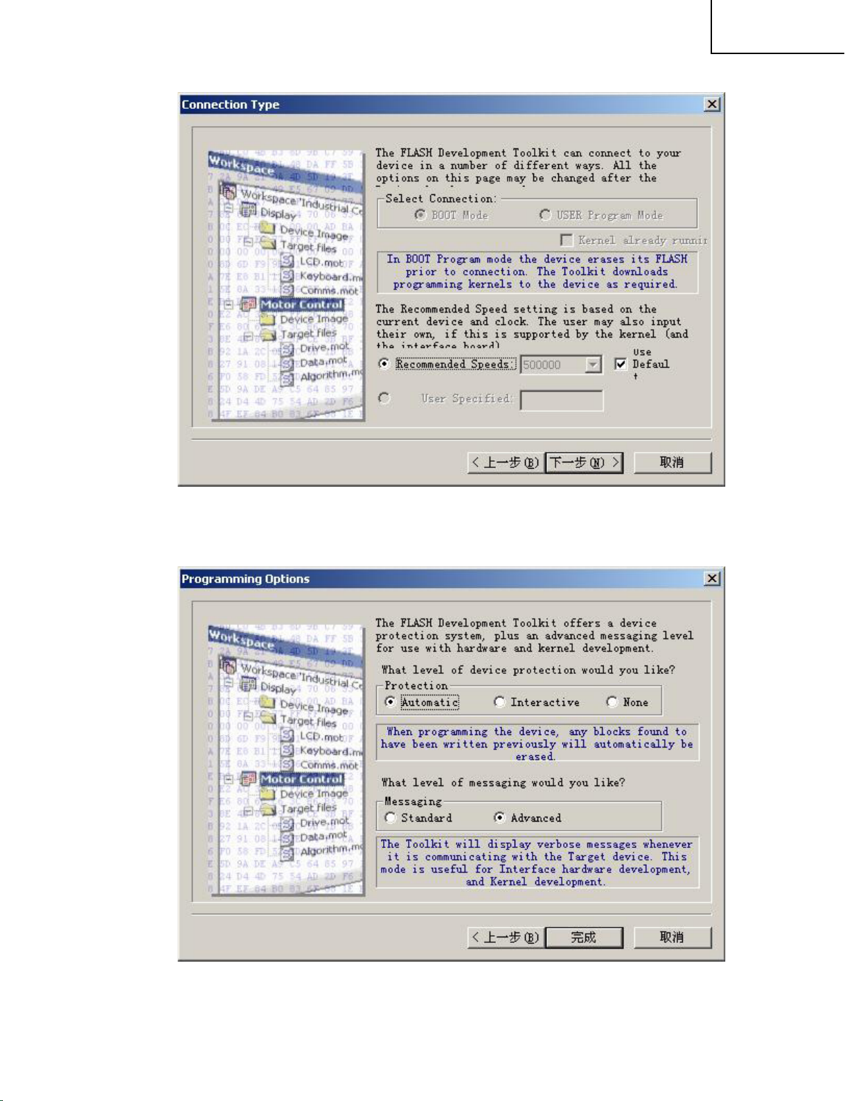
2. Upgrading of each microprocessor software
2.1 Sub microprocessor software version upgrade
1). Install “Flash Development Toolkit” in CD-ROM.
Connect E8a Emulator Debugger to PC from USB port. (driver in CD ROM)
2). Connect E8 writer to LCD’s 20PIN port which near INPUT4 terminal.
It may need a converter (see the “convertor1).
3). Run “Flash Development Toolkit” in start menu.
4). Choose “Create a new project workspace”.
LC-19SK25U/U-W
LC-19SB25U/U-W
LC-19SB15U
LC-19D45U
If second time, you can select “open a recent project work”.
Choose “OK”.
5). Input any name, and remember the Directory.
19
Page 20
20
LC-19SK25U/U-W
LC-19SB25U/U-W
LC-19SB15U
LC-19D45U
6). Choose Device: R8C R5F21246
7). Select “E8a” and Next.
Page 21
8). Next
LC-19SK25U/U-W
LC-19SB25U/U-W
LC-19SB15U
LC-19D45U
9). Finish it.
21
Page 22
22
LC-19SK25U/U-W
LC-19SB25U/U-W
LC-19SB15U
LC-19D45U
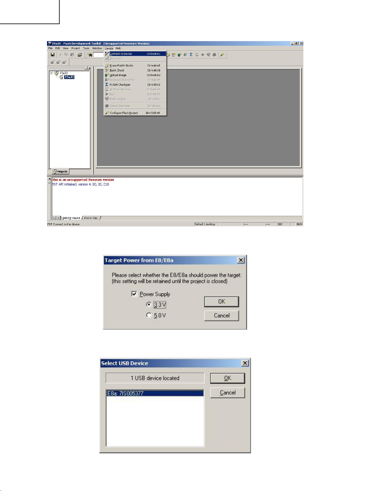
10). Menu->Device->Connect to Device
11). Choose Target Power: 3.3V
12). OK
Page 23
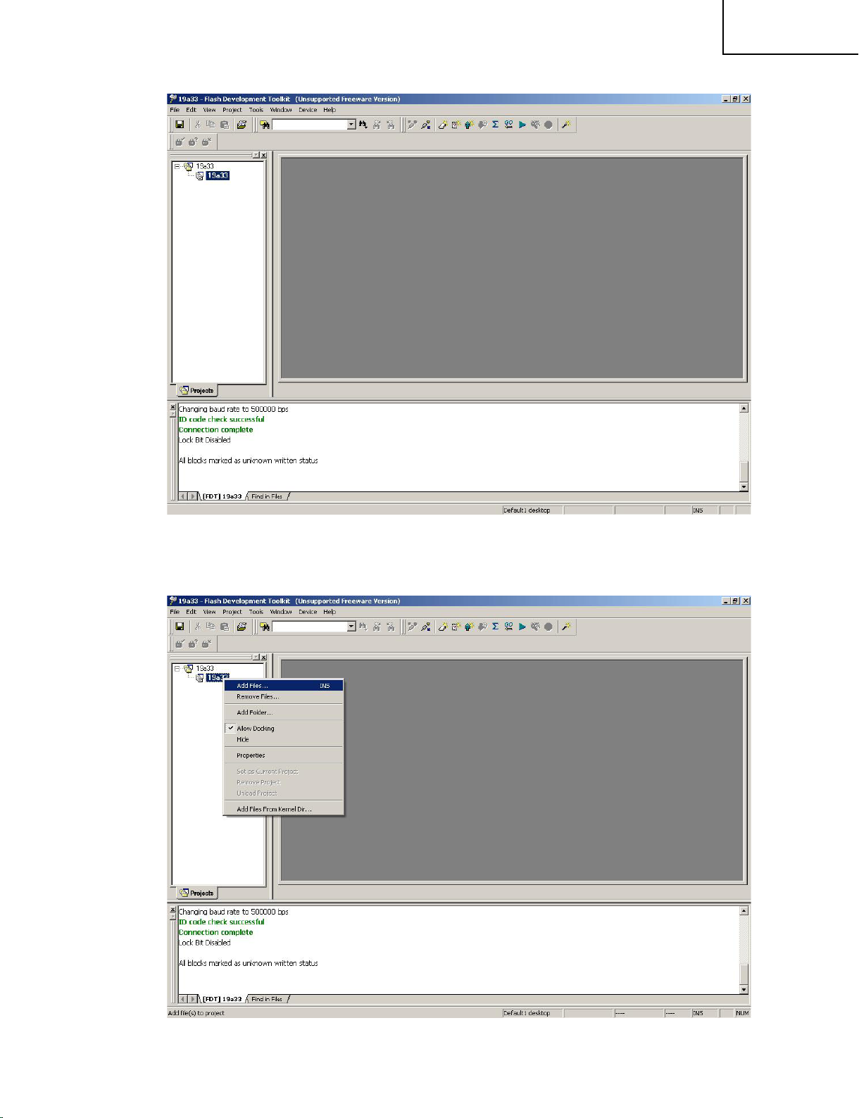
13). Connection Complete
LC-19SK25U/U-W
LC-19SB25U/U-W
LC-19SB15U
LC-19D45U
14). Right hit the Project file, and choose “Add Files…”
23
Page 24
24
LC-19SK25U/U-W
LC-19SB25U/U-W
LC-19SB15U
LC-19D45U
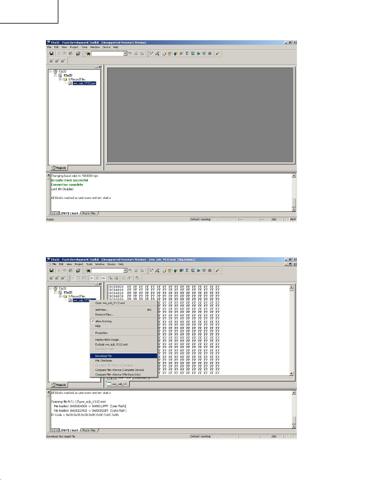
15). Add the MOT file, which you want to writer to IC. After it, the MOT file name will display in it.
16). Right hit the MOT file and choose “Download file”, the begin downloading.
Page 25
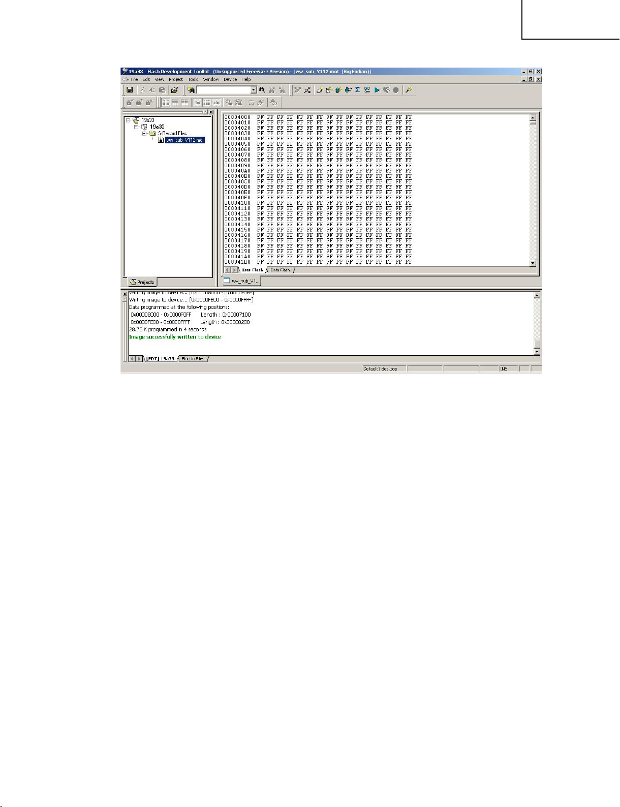
17). After downloading, it will hit that “Image successfully written to device”.
LC-19SK25U/U-W
LC-19SB25U/U-W
LC-19SB15U
LC-19D45U
18). Then SUB soft writer finish.
25
Page 26
26
LC-19SK25U/U-W
LC-19SB25U/U-W
LC-19SB15U
LC-19D45U
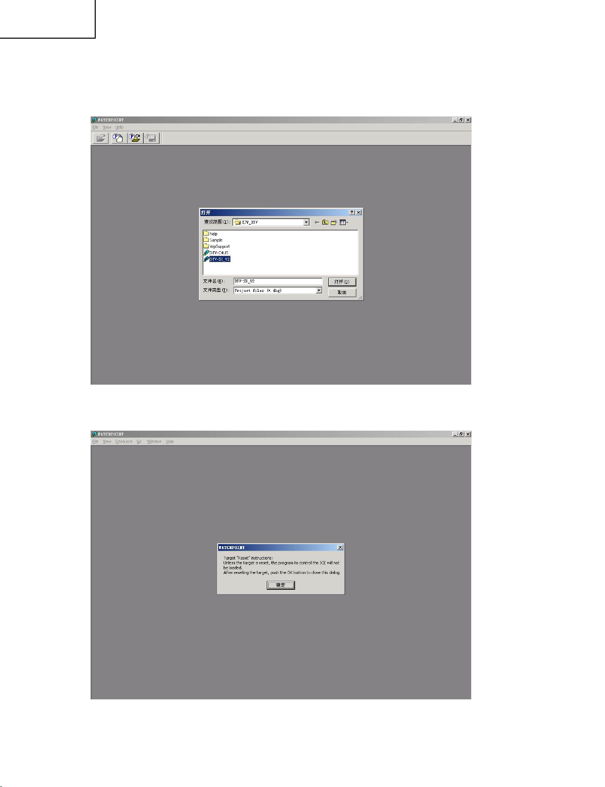
2.2 Main software version upgrade
Install soft in CD- ROM : WATCHPOINT-EJW\Disk1\SETUP.EXE
USB Driver: CD-ROM folder “USB Driver”. Unzip “DTV FILES_Unicorn” to root install directory.
Make a connecting (refer to “convertor2”)
1). Connect writer to pc by USB, connect writer to 20 pin socket in main pwb by SH2/SH3 and connecting.
2). AC in
Then press Enter
Page 27
LC-19SK25U/U-W
LC-19SB25U/U-W
LC-19SB15U
LC-19D45U
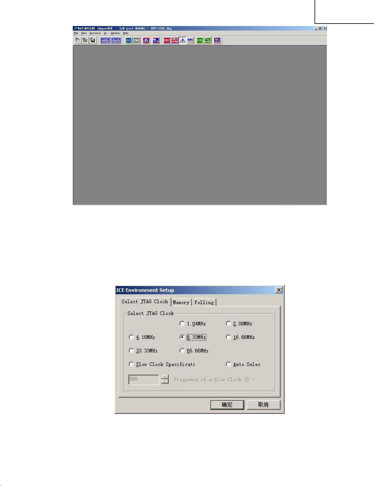
4). Enter menu Resource->ICE Environment… ,and set the JTAG Clock to 8.33MHz.
27
Page 28
28
LC-19SK25U/U-W
LC-19SB25U/U-W
LC-19SB15U
LC-19D45U
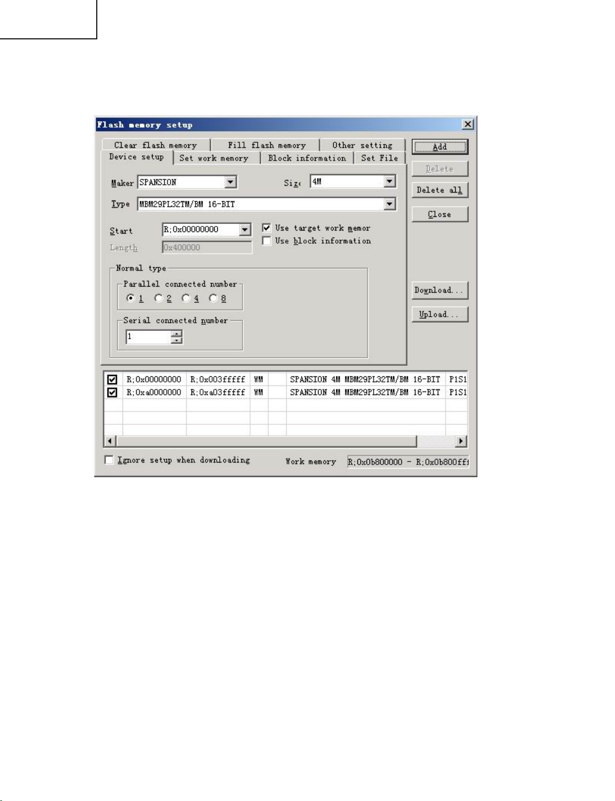
5). Enter menu Resource->Flash Memory->Device setup
Maker: SPANSION Size: 4M
Type: MBM29PL32TM/BM 16BIT
1. Start=0x00000000 “ADD”
2. Start=0xa0000000 “ADD”
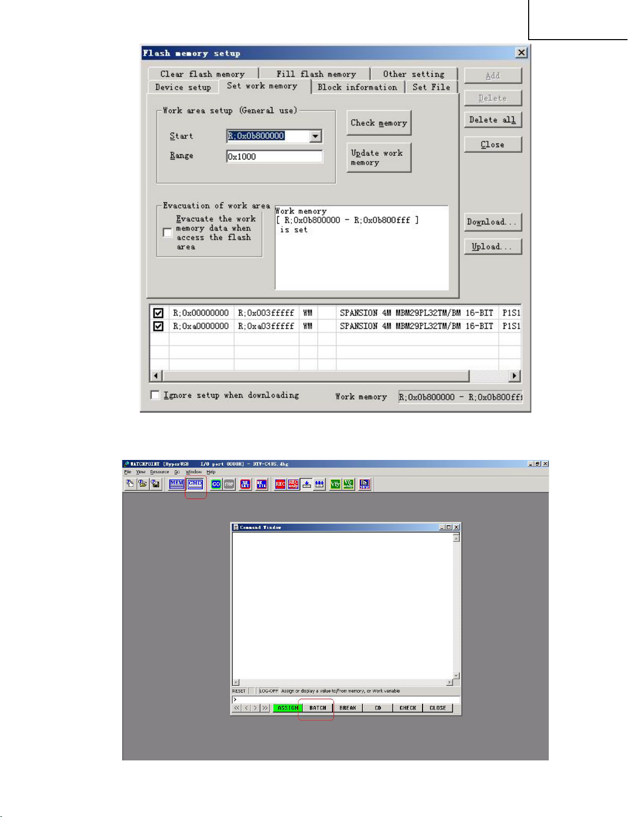
6). Flash Memory setup:
Start=0x0b800000 Range=0x1000
Press “Update work memory” then close.
Page 29
LC-19SK25U/U-W
LC-19SB25U/U-W
LC-19SB15U
LC-19D45U
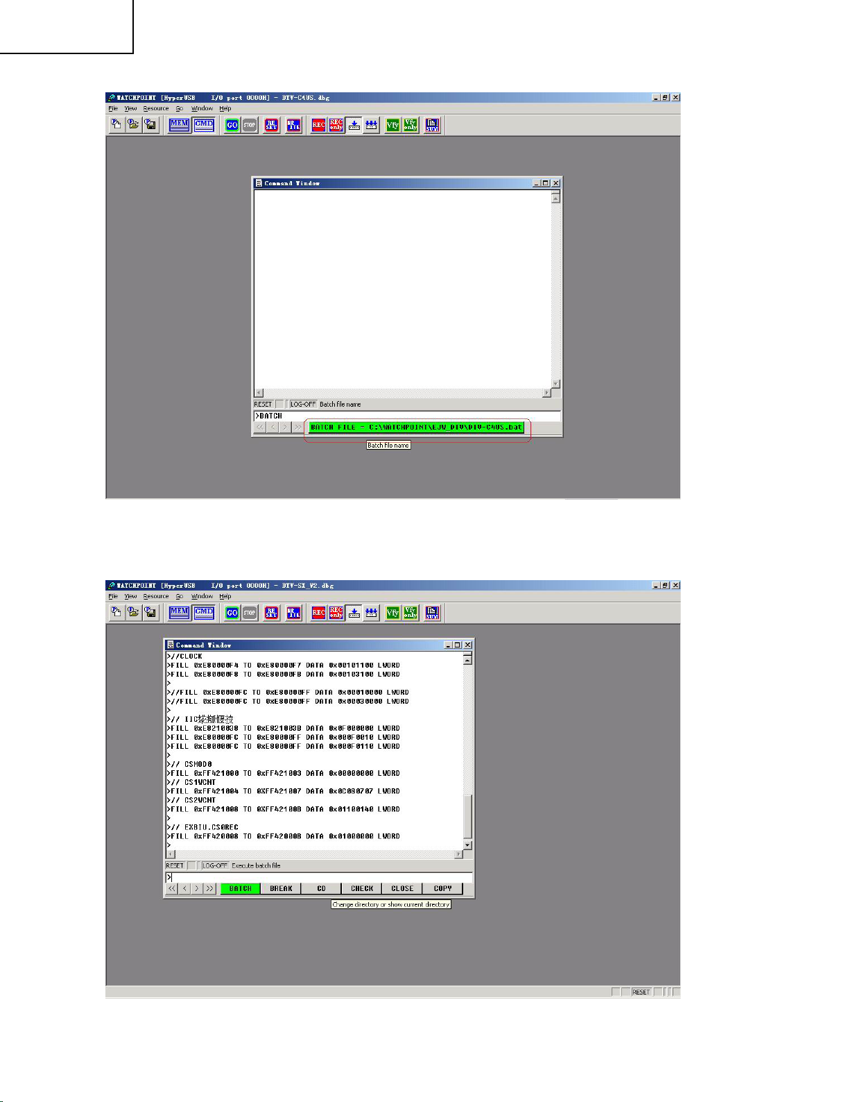
7). Press CMD and press BATCH
29
Page 30
30
LC-19SK25U/U-W
LC-19SB25U/U-W
LC-19SB15U
LC-19D45U
8). Press the GREEN character, and press ENTER
9).
Page 31

10). Enter menu Resource->Flash Memory->Clear flash memory
Choose “Clear all devices those included …” and “Start”.
LC-19SK25U/U-W
LC-19SB25U/U-W
LC-19SB15U
LC-19D45U
31
Page 32

32
LC-19SK25U/U-W
LC-19SB25U/U-W
LC-19SB15U
LC-19D45U
11). Chip erasing
12). After erase the display as follow:
Page 33

13). Press MEM, and press “Magnifier” to check the DUMP, all of them are “FF”
LC-19SK25U/U-W
LC-19SB25U/U-W
LC-19SB15U
LC-19D45U
14). Select Resource->Download, and ADD MOT file:
33
Page 34

34
LC-19SK25U/U-W
LC-19SB25U/U-W
LC-19SB15U
LC-19D45U
15). Press Download, begin writer data
16). Waiting about 2 minutes, it’s up to 100%, writing finish.
Check the memory dump again, the data appeared
Page 35

17). Close WATCHPOINT, and save the project file
LC-19SK25U/U-W
LC-19SB25U/U-W
LC-19SB15U
LC-19D45U
18). Unplug the AC cord and connector.
Main software update finished.
35
Page 36

36
LC-19SK25U/U-W
LC-19SB25U/U-W
LC-19SB15U
LC-19D45U
3. Adjustment procedure
3.1 Plug the AC power cord directly into a wall outlet.
3.2 Calling the adjustment process mode
There are two ways to call this mode.
appears at the top left of the screen to indicate the inspection process mode.)---Press the CH (s)key
and VOL(−)key at once.(The adjustment process mode screen shows up.)_To quit, turn off the power.
(Or turn off the power switch or turn off the remote controller.)
3.3 Key operation in the adjustment process
Basic operation
Selecting the receiving channels
Snap press: The channels are turned up and down one by one .
Continuous press: The next receivable channel is searched.
the cursor key and VOL(+)(−) keys
a page is already selected and the MENU key is pressed, the top item on the next page is selected.
page is selected.
selected item.
Hierarchical shift
item shows up.
3.4 Adjustment
3.4.1
Signal generation: LEADER LT448
Signal: color BAR.
Setting: 02: 1080i/59.94(30sf)
H: 33.72 KHz V: 29.97Hz
Note: Please use the third color Bar of LT448 generator
When “AUTO GAIN-OFFSET OK” appears , this adjustment is complete
Signal: color BAR.
Setting: 15: 480i/60
H: 15.73 KHz V: 29.97Hz
Note: Please use the third color Bar of LT448 generator
When “AUTO GAIN-OFFSET OK” appears , this adjustment is complete
Turn on the power and press the “ADJUST PROCESS” key on the remote controller.
∗
For servicing: Hold down the INPUT key and VOL (−) key at once, and turn on the power switch.(“K”
∗
Using the CH(
∗
Various adjustments: The items are adjusted one by one by selecting on the menu screen and using
∗
With the CURSOR UP/DOWN keys, select an adjustment item.
∗
Using the MENU key, the adjustment items are selected one after another. When the bottom item on
∗
If any item on a page is selected and the preset key is pressed, the top item on the next page is selected.
∗
)/(s) keys, turn up and down an actual receiving channel.
r
Page1- Page2- Page3- Page7- Page9- Page10…..
If any item on a page is selected and the manual memory key is pressed, the top item on the same
∗
Using the CURSOR LEFT/RIGHT keys and VOL(+)(−) keys, turn up and down the setting of a
∗
When the ENTER key is pressed on any item other than I2C DATA on page 4,the setting page of the
∗
To quit the setting page, press the front screen key.
∗
AD TRANSFORM LEVEL Adjustment
3.4.1.1 Input 1080i signal
Input 1080i color bar signal (75%)
1
Adjusting AUTO GAIN-OFFSET in page 3 of DVP (M2-HD) to RUN .
2
3.4.1.2 Input 480i signal
Input 480i color bar signal (75%)
1
Adjusting AUTO GAIN-OFFSET in page 4 of DVP (M2-SD) to RUN .
2
3.4.1.3 Input PC XGA signal
Input XGA color bar signal (RGB)
1
Signal generation: LEADER LT448
Page 37

LC-19SK25U/U-W
LC-19SB25U/U-W
LC-19SB15U
LC-19D45U
Signal: color BAR (SATURATION 75%)
Setting: 28: XGA
H: 48.36KHz V: 60Hz
SYNC: OFF
Note: Please use the color Bar of SATURATION
Adjusting AUTO GAIN-OFFSET in page 5 of DVP(M2-PC)to RUN .
2
When “AUTO GAIN-OFFSET OK” appears , this adjustment is complete
NOTE: If want to set all item to ON,please set to RUN in ADJUST PROCESS.
3.5 TEMP Adjustment
3.5.1 Receive US-10ch(JPN-8ch) the standard color bar signal
3.5.2 See if the “YDATA” reading (maximum) on Adjustment Process Page 1 is within the range in the
follow table. If not, adjust the “TEMP ALL” setting on the same page to have the “YDATA” reading
(maximum) within this range.
MODEL A3KL19SK25U
SETTING VALUE (NTSC) 96-100
Refence
(Adjustment Process Menu Page 1)
0 1 2 3 4 5 6 7 8 9 10 11 12 13 14 15 16 17 18 19 20 21 22 23 24 25 26
0 D V P 1
1
T A M P 1 L 9 6
●
2 Y D A T A 9 9
3 T A M P 1 H 1 0 0
4 T A M P A L L O F F
5 N T S C T A M P 1 3 2
6 P A L - M T A M P 3 9
7 P A L - N T A M P 3 9
37
Page 38

38
LC-19SK25U/U-W
LC-19SB25U/U-W
LC-19SB15U
LC-19D45U
㪈㩷 㪉㩷 㪊㩷 㪋㩷 㪌㩷 㪍 㪎㩷 㪏㩷 㪐㩷 㪈㪇㩷 㪈㪈 㪈㪉 㪈㪊 㪈㪋 㪈㪌 㪈㪍
㪈㩷 㩷 㩷 㩷 㩷 㩷 㩷 㩷 㩷 㩷 㩷 㩷 㩷 㩷 㩷 㩷 㩷 㩷 㩷 㩷 㩷 㩷 㩷 㩷 㩷 㩷 㩷
㪉㩷 㩷 㩷 㩷 㩷 㩷 㩷 㩷 㩷 㩷 㩷 㩷 㩷 㩷 㩷 㩷 㩷 㩷 㩷 㩷 㩷 㩷 㩷 㩷 㩷 㩷 㩷
㪊㩷 㩷 㩷 㩷 㩷 㩷 㩷 㩷 㩷 㩷 㩷 㩷 㩷 㩷 㩷 㩷 㩷 㩷 㩷 㩷 㩷 㩷 㩷 㩷 㩷 㩷 㩷
㪋㩷 㩷 㩷 㩷 㩷 㩷 㩷 㩷 㩷 㩷 㩷 㩷 㩷 㩷 㩷 㩷 㩷 㩷 㩷 㩷 㩷 㩷 㩷 㩷 㩷 㩷 㩷
㪌㩷 㩷 㩷 㩷 㩷 㩷 㩷 㩷 㩷 㩷 㩷 㩷 㩷 㩷 㩷 㩷 㩷 㩷 㩷 㩷 㩷 㩷 㩷 㩷 㩷 㩷 㩷
㪍㩷 㩷 㩷 㩷 㩷 㩷 㩷 㩷 㩷 㩷 㩷 㩷 㩷 㩷 㩷 㩷 㩷 㩷 㩷 㩷 㩷 㩷 㩷 㩷 㩷 㩷 㩷
㪎㩷 㩷 㩷 㩷 㩷 㩷 㩷 㩷 㩷 㩷 㩷 㩷 㩷 㩷 㩷 㩷 㩷 㩷 㩷 㩷 㩷 㩷 㩷 㩷 㩷 㩷 㩷
㪏㩷 㩷 㩷 㩷 㩷 㩷 㩷 㩷 㩷 㩷 㩷 㩷 㩷 㩷 㩷 㩷 㩷 㩷 㩷 㩷 㩷 㩷 㩷 㩷 㩷 㩷 㩷
㪐㩷 㩷 㩷 㩷 㩷 㩷 㩷 㩷 㩷 㩷 㩷 㩷 㩷 㩷 㩷 㩷 㩷 㩷 㩷 㩷 㩷 㩷 㩷 㩷 㩷 㩷 㩷
㪈㪇㩷 㩷 㩷 㩷 㩷 㩷 㩷 㩷 㩷 㩷 㩷 㩷 㩷 㩷 㩷 㩷 㩷 㩷 㩷 㩷 㩷 㩷 㩷 㩷 㩷 㩷 㩷
㪈㪈㩷 㩷 㩷 㩷 㩷 㩷 㩷 㩷 㩷 㩷 㩷 㩷 㩷 㩷 㩷 㩷 㩷 㩷 㩷 㩷 㩷 㩷 㩷 㩷 㩷 㩷 㩷
㪈㪉㩷 㩷 㩷 㩷 㩷 㩷 㩷 㩷 㩷 㩷 㩷 㩷 㩷 㩷 㩷 㩷 㩷 㩷 㩷 㩷 㩷 㩷 㩷 㩷 㩷 㩷 㩷
㪈㪊㩷 㩷 㩷 㩷 㩷 㩷 㩷 㩷 㩷 㩷 㩷 㩷 㩷 㩷 㩷 㩷 㩷 㩷 㩷 㩷 㩷 㩷 㩷 㩷 㩷 㩷 㩷
㪈㪋㩷 㩷 㩷 㩷 㩷 㩷 㩷 㩷 㩷 㩷 㩷 㩷 㩷 㩷 㩷 㩷 㩷 㩷 㩷 㩷 㩷 㩷 㩷 㩷 㩷 㩷 㩷
㪈㪌㩷 㩷 㩷 㩷 㩷 㩷 㩷 㩷 㩷 㩷 㩷 㩷 㩷 㩷 㩷 㩷 㩷 㩷 㩷 㩷 㩷 㩷 㩷 㩷 㩷 㩷 㩷
㪈㪍㩷 㩷 㩷 㩷 㩷 㩷 㩷 㩷 㩷 㩷 㩷 㩷 㩷 㩷 㩷 㩷 㩷 㩷 㩷 㩷 㩷 㩷 㩷 㩷 㩷 㩷 㩷
㪈㪎㩷 㩷 㩷 㩷 㩷 㩷 㩷 㩷 㩷 㩷 㩷 㩷 㩷 㩷 㩷 㩷 㩷 㩷 㩷 㩷 㩷 㩷 㩷 㩷 㩷 㩷 㩷
㪈㪏㩷 㩷 㩷 㩷 㩷 㩷 㩷 㩷 㩷 㩷 㩷 㩷 㩷 㩷 㩷 㩷 㩷 㩷 㩷 㩷 㩷 㩷 㩷 㩷 㩷 㩷 㩷
㪈㪐㩷 㩷 㩷 㩷 㩷 㩷 㩷 㩷 㩷 㩷 㩷 㩷 㩷 㩷 㩷 㩷 㩷 㩷 㩷 㩷 㩷 㩷 㩷 㩷 㩷 㩷 㩷
㪉㪇㩷 㩷 㩷 㩷 㩷 㩷 㩷 㩷 㩷 㩷 㩷 㩷 㩷 㩷 㩷 㩷 㩷 㩷 㩷 㩷 㩷 㩷 㩷 㩷 㩷 㩷 㩷
3.5.3 Common bias Adjustment
Feed in built-in signal (See follow picture)
1
Adjust the “COM BIAS” setting so that the peak-to-peak of the wave be minimized.
2
Page 39

3.5.4 White balance adjustment
Adjustment item Adjustment conditions Adjustment procedure
1 Setting Backlight: +16
(MAX)
2 Automatic adjust-
ment execution
For detailed adjustment procedure refer to "Kameyama Model Integral WB Adjustment
Specifications".
1) Make the following settings for the set.
AV MODE: [DYNAMIC]
Backlight: +16
Aging time: Min. 30 minutes
2) Connect the white balance adjustment tool to the set.
3) The cross is displayed by execute command of RS232C and the probe position is
set to the center of the screen(please attention the operation manual of CA210).
4) The cross is disappeared by execute command of RS232C.
Adjusting the picture by execute command of RS232C
[Adjustment prcedure]
1) Using the remote controller,transmit the "monitor adjustment process" code.
2) Set the 6th point to the specified gradation level,With the strongest color being fixed,
turn down the R,G and B settings to their reference levels.
3) Set the 5th point to the specified gradation level.
Correct the G setting (304 x 6th point G setting /816) (rounded off), and make the R
and B settings to their reference levels.
* Initial R, G and B settings at point 6: Gradation level set at 816
* Initial R and B settings at points 5:Correct the setting same remainder of RGB setting
at each point (This is because the adjustment is made to achieve the same remainder
of RGB setting/4 at each point).
LC-19SK25U/U-W
LC-19SB25U/U-W
LC-19SB15U
LC-19D45U
[Adjustment value]
As per the "standard set" submitted by Engineering Department
[Adjustment reference] Instrument:[Minolta CA-210] Engineering instrument
Level Reference Adj.spec Ins.spec
point 6 816
point 5 304
Note Set conditions for inspection
X=0.272
y=0.277
X=0.272
y=0.277
AV MODE: [DYNAMIC] (Reset)
Monochrome: ON
Aging Time: Min. 30 minutes
3.6 Factory setting
3.6.1 Making factory settings
Use the adjustment remote controller for the factory settings.
3.6.1.1 Hold on the remote controller’s FACTORY SETTING key.
3.6.1.2
If background of screen is green,the settings are complete.
Sever seconds later, "SETTING COMPLETE""TV VER *.**" appears at the center of the screen.
SETTING COMPLETE
0.001
±
0.002
±
0.002
±
0.004
±
TV VER ∗.
∗∗
3.6.1.3 Power off the set.
Note: Do not turn on the power once the factory settings have been made. Otherwise the factory
setting must be made again.
3.7 Software version
The software version will be reported at the Conversion Judgment Meeting. Possible modifications that will
follow will be reported using the Modifications Report.
Main microprocessor
∗
Monitor microprocessor
∗
EDIT data(HDMI/analog RGB)
∗
39
Page 40

40
LC-19SK25U/U-W
LC-19SB25U/U-W
LC-19SB15U
LC-19D45U
PUBLIC MODE SETTING PROCEDURE
1. How to start Public Mode
There are the following two ways to get the public mode setup screen displayed.
•
In the adjustment process mode, turn on "HOTEL MODE". Also press the "CH (r)" and "VOL (+)" keys
1
on the set at once and turn on the power.
1) Press the "INPUT" and "VOL (+)" keys on the set at once and turn on the power.
2
2) Get the password input screen displayed.
— — —
— —
✽
Procedure
The input starts with the leftmost digit.
•
Use the numeric keys [1] thru [9] and [0] keys on the remote con
•
troller. The other keys are not acceptable.
With a numeric-key input, "–" will change to "
•
will move one digit to the right.
With all the 3
•
digits entered, the password will be verified.
". The input position
✽
-
✽
✽
✽
3) The 3-digit password is now verified.
The password [0] [2] [7] provides for the public mode screen. (This screen comes on with whatever ad-
justment process settings.)
With any other passwords, the screen changes to the normal mode.
Page 41

LC-19SK25U/U-W
LC-19SB25U/U-W
2. How to exit Public Mode
There are the following ways to quit the public mode setup screen.
Turn off "HOTEL MODE" in the adjustment process mode. (✩)
•
screen, but for quitting the mode itself.
Turn off the power with the "POWER" key. (★)
•
Select "ENTER". (★)
•
... "HOTEL MODE" stays on in the adjustment process mode.
★
... The settings will be back to the factory ones.
✩
This way alone is not for quitting the setup
←
3. Public Mode Setting Values
With the factory settings made, the public mode settings get initialized. (The adjustment process remains in-
•
tact.)
4. Public Mode Menu
The guidance is not displayed onscreen.
Setup procedure
To move the cursor up and down, use the "cursor UP/DOWN" key (remote controller) and "
•
(remote controller and set).
To change the settings, use the "cursor RIGHT/LEFT" key (remote controller) and "VOL (+)/(–)" key (remote
•
controller and set).
To save new settings, keep the cursor at "EXECUTE" and use the "ENTER" key (remote controller).
•
CH (r)/(s)" key
LC-19SB15U
LC-19D45U
Public mode
Power on fixed [Variable ]
Maximum volume [ 60 ]
Volume fixed [Variable ]
Volume fixed level [ 60 ]
RC button [Respond ]
Panel button [Respond ]
Menu button [Respond ]
On screen display [Yes ]
Blue screen [No ]
Input mode start [Normal ]
Input mode fixed [Variable ]
Reset
ENTER
41
Page 42

42
LC-19SK25U/U-W
LC-19SB25U/U-W
LC-19SB15U
LC-19D45U
5. On Setting Items
* "EZ-SETUP" discussed below indicates "EZ-SETUP after the first power-on".
(1) POWER ON FIXED
Selection
Default
Explanation
Limit in Setting
Exception
Remarks
(2) MAXIMUM VOLUME
Selection
Default
Explanation
Limit in Setting
Exception
Remarks
Selection between "Variable" and "Fixed" (loop provided)
Variable
In "Fixed" setting, the power-off by the power key of the unit is invalidated and the image is kept being received. The power can be turned off by stopping the power supply from AC.
Refer to the "Power-On Fixed" sheet.
None
Adjustment from 0 to 60 (no loop)
60
Sound volume can not be adjusted higher than the preset value.
•
When the sound volume is set lower than 59, only figures are displayed and the sound volume bar is
not displayed.
•
The maximum sound volume for ON-timer (Wake up timer) is limited also to the preset value.
None
•
In line output (sound volume variable), the sound volume can be adjusted from 0 to 60 irrespective of
pre-adjusted value.
•
When the sound volume is set higher than the MAX setting by the adjusting process, the sound volume
control operation is prohibited for turn-up and the sound volume should be turned down to MAX in this
state.
(3) VOLUME FIXED
Selection
Default
Explanation
Limit in Setting
Exception
Remarks
Selection between "Variable" and "Fixed" (loop provided)
Variable
Sound volume is fixed and made invariable.
•
The sound volume for the ON-timer (Wake up timer) is fixed also without display of menu. Besides, the
setting is made impossible. (Basically, the menu is not displayed.)
•
The following keys become invalid:
• Sound volume Up/Down (VOL +/-) [for both remote control and the unit]
• Mute (MUTE)
None
•
In line output (sound volume variable), the sound volume can be adjusted from 0 to 60 irrespective of
pre-adjusted value.
•
As for sound volume fixing and sound volume MAX level, the sound volume fixing has priority.
•
Once the sound volume has been changed by adjustment process, it should be set back to the sound
volume preset by sound volume fixing level when the adjustment process ends .
(4) VOLUME FIXED LEVEL
Selection
Default
Explanation
Limit in Setting
Exception
Remarks
Adjustment from 1 to 60 (no loop)
60
The sound volume to be fixed by "Volume fixed" is determined.
None
None
Setting is valid only when "Volume fixed" is selected for "fixed".
Page 43

(5) R/C BUTTON
Selection
Default
Explanation
Limit in Setting
Exception
Remarks
Selection between "Respond" and "No respond" (loop provide)
Respond
Keys acceptable by remote control are limited or reception of keys can be prohibited.
In "No respond" setting, all the keys (including the power key) are not accepted.
•
•
All the keys can be used in adjustment process, inspection mode and hotel menu irrespective of setting.
•
All the keys can be used also in the initial EZ-Setup after power-ON irrespective of setting.
(6) PANEL BUTTON
Selection
Default
Explanation
Limit in Setting
Exception
Remarks
Selection between "Respond" and "No respond" (loop provide)
Respond
All the operations by keys (except the power key) of the unit can be invalidated.
•
Inspection mode and hotel menu mode can be started irrespective of setting.
•
All the keys can be used in adjustment process, inspection mode and hotel menu irrespective of setting.
•
LC-19SK25U/U-W
LC-19SB25U/U-W
LC-19SB15U
LC-19D45U
Adjustment process, factory setting, inspection process and hotel only keys are valid irrespective of setting.
In U.S.A model, all the keys can be used also in the initial EZ-Setup after power-ON irrespective of setting.
(7) MENU BUTTON
Selection
Default
Explanation
Limit in Setting
Exception
Remarks
Selection between "Respond" and "No respond" (loop provide)
Respond
In "No respond" setting, the menu operation by the menu key of the remote control and the menu key of
the unit are invalidated.
•
Inspection mode and hotel menu mode can be started irrespective of setting.
•
All the keys can be used in adjustment process, inspection mode and hotel menu irrespective of setting.
•
All the keys can be used also in the initial EZ-Setup after power-ON irrespective of setting.
(8) ON SCREEN DISPLAY
Selection
Default
Explanation
Limit in Setting
Others
Exception
Remarks
Selection between "Yes" , "NO" (loop provide)
Yes
The following OSD displays are made ineffective.
Displays of menu group, channel call, sound volume bar and direct key call
•
ON-timer (Wake-up timer) is cleared and set to "OFF".
•
Set time of the OFF-timer (SLEEP TIMER) is cleared.
•
Setting of the no-signal power-OFF (AUTO POWER OFF) is cleared to "OFF".
•
Setting of the no-operation power-OFF is cleared to "OFF".
•
Keys falling under any of the following items become invalid.
1Appearance of screen changes and the sound changes.
2Personal functions which are hard to restore.
Screen display, menu, OFF-timer, ON-timer, AV MODE, screen size switching, clock setting, treble
emphasis, AUDIO ONLY, sound changeover, LANGUAGE, CLOSED CAPTION
•
Simple input switching is generated. Those which are restored soon after leaving as they are and may
be requested for change by customer are not prohibited.
Brightness sensor (BACKLIGHT) .
•
Such a caution which is displayed independently is displayed as it is.
Non-responding signal caution.
•
When CC has already been ON, CLOSED CAPTION is displayed.
43
Page 44

44
LC-19SK25U/U-W
LC-19SB25U/U-W
LC-19SB15U
LC-19D45U
(9) BLUE SCREEN
Selection
Default
Explanation
Limit in Setting
Exception
Remarks
(10) INPUT MODE START
Selection
Default
Explanation
About options
Limit in Setting
Exception
Remarks
Selection between "Yes" , "NO" (loop provide)
No
In "Yes" setting, when don't receive any signal or no signal input, the screen is blue.
None
None
Selection between "Normal" , "Air/Cable(CH~)
INPUT 1/2/3/4" (loop provide)
", "
Normal
In power-ON, the input source to be started or channel can be set.
(In standard mode, the operation follows the last memory.)
•
All the input sources in the model are made selectable.
•
When the input/output switchable input source is selected and the input source is set to output, the set-
ting of input/output switching is changed to input at the execution of hotel menu. In addition, the input/
output switching by menu is prohibited.
•
In TV mode, the channel to be set follows the last memory and the content of the last memory is includ-
ed in the notation by options. Ex.) TV (CH2), TV (CH4) etc.
•
The display of channel setting menu and the channel setting operation are prohibited.
None
•
In setting at "Normal", the setting of "Input mode fixed" is changed to "Variable" and selection should
be prohibited.
(11) INPUT MODE FIXED
Selection
Default
Explanation
Limit in Setting
Exception
Remarks
Selection between "Variable" and "Fixed" (loop provide)
– (Variable)
The input mode is fixed at the input source or the channel set at the "Input mode start" in 9 and other input sources and channels can be made non-selectable.
•
With the execution of hotel mode, the input source is forced to change to that set by "Input mode start"
and the channel switching and input switching are prohibited thereafter.
•
ON-timer's (Wake-up timer) channel items are not displayed or the operation is prohibited. (Basically,
they are not displayed.)
•
The following keys are invalidated.
CH
'"
~However, the keys (input switching and CH '" keys) of the unit for menu operation remain valid.
None
•
In the following case, setting is cancelled and mode is changed to "Variable".
1When the setting of "Input mode start" is set to
, direct tuning button, FLASHBACK, input
NORMAL.
Page 45

TROUBLESHOOTING TABLE
No power supply (Front LED does not light up) and no power-up even is turned on (Front LED light up to blue)
Yes
No
No
Yes
No
Yes
No
Yes
Replace F7502 when the fuse is brown.
Connect the harness and Cable properly.
Connect the AC cord and turn on the power.
Is the AC cord connected?
Are the harness and Cable connected
properly?
No
Connect the harness and Cable properly.
Are the harness and Cable connected
properly?
Is the voltage of C7528 approx. 168V?
Are F7502 normal?
Yes
No
Is the main unit normal?
Yes
No
Yes
Check the rectifier circuit of UR12V
Does AC-CTRL (pin9 of SC7501) become High (approx. 3.3V)?
Are UR12V supplied?
Turn on the power again,and check if
the unit works normally.
Check if L7501,TH7501 and D7527 are normal.
LC-19SK25U/U-W
LC-19SB25U/U-W
LC-19SB15U
LC-19D45U
45
Page 46

46
LC-19SK25U/U-W
LC-19SB25U/U-W
LC-19SB15U
LC-19D45U
No audio output during UHF/VHF reception
Yes
No
No
Yes
No
Yes
Yes
No
Yes
Check IC501/IC502 and peripheral circuits.
Check circuits between IC1101 and IC501/IC502.
Check the filter circuits (Q1102, Q1103) and
peripheral circuits.
Check the tuner and peripheral circuits.
Is SIF output from the tuner (TU1101_Pin15) normal?
Is input signal fed to pin21 of IC1101?
Are audio signals from pins 30 and 29 of IC1101 to pins
13 of IC501 and IC502 normal?
Check the connector (P301) of MAIN_UNIT and around the
speakers.
Are audio outputs of pin 3 of IC501 and IC502 normal?
Are I2S signals output from pin 2,pin 4,pin 7 and pin 8 of
IC302 to pin W5,pin W6, pin Y6 and pin AA6 of IC801 normal?
No
Yes
Check the circuits between IC501/502 and IC302.
Are audio input of pin 10 and pin 12 of IC302 normal?
Yes
No
Check IC1302 and peripheral circuits.
Is audio output from IC1302 normal?
No
Check the circuits between IC302 and IC801.
No
Yes
Check IC801 and peripheral circuits.
Are audio signal output from pin AA3 and pin AA4 of
IC801 to pin 5 and pin 9 of IC1302 normal?
TROUBLESHOOTING TABLE (Continued)
Page 47

TROUBLESHOOTING TABLE (Continued)
No audio output from external input
<<HDMI>>[INPUT-3]
Is L-ch audio signal fed from input terminal J503 to pin 1 of IC501?
Is R-ch audio signal fed from input terminal J503 to pin 1 of IC502?
<<PC>>[INPUT-4]
Is L-ch audio signal fed from input terminal J401 to pin 5 of IC501?
Is R-ch audio signal fed from input terminal J401 to pin 5 of IC502?
Are audio signals from pin 3 of IC501 and IC502 to pins 10 and 12 of
IC302 normal?
<<INPUT-1>>
Is L-ch audio signal fed from input terminal J501 to pin 12 of IC501?
Is R-ch audio signal fed from input terminal J501 to pin 12 of IC502?
<<INPUT-2>>
Is L-ch audio signal fed from input terminal J502 to pin 14 of IC501?
Is R-ch audio signal fed from input terminal J502 to pin 14 of IC502?
No
Check the circuits between IC501/IC502 and IC302.
Check the Circuits between IC302 and IC801.
Is audio input from pin 4 of IC302 to pin W6 of IC801 normal?
No
Check IC1302 and peripheral circuits.
Is audiio output from IC1302 normal?
No
Check the connector (P1301) of SUB_UNIT and around the speakers
Yes
Yes
Yes
Yes
LC-19SK25U/U-W
LC-19SB25U/U-W
LC-19SB15U
LC-19D45U
47
Page 48

48
LC-19SK25U/U-W
LC-19SB25U/U-W
LC-19SB15U
LC-19D45U
<Component video signal input> No video output (INPUT-1)
Yes
No
Check between J501 and pins 7,8 and 9 of P501.
(Q501, Q502, Q503)
Select INPUT-1 and the input signal on the input switching
menu screen.
No video output from extermal input <<INPUT-1>>
Is video signal fed to pins 7, 8 and 9 of P501?
No
Yes
No
Yes
Check IC801 and peripheral circuits.
Check between IC801 and IC501.
Is video signal fed to pins K2, M2 and P3, T2 of IC801?
Are signals from A6, A1, E1, E2, W5, W6, W7, Y6, AA6 of
IC801 normal?
Check IC9201 and peripheral circuits.
Yes
TROUBLESHOOTING TABLE (Continued)
Page 49

TROUBLESHOOTING TABLE (Continued)
<Composite video signal/S-video signal input> No video output (INPUT2)
Yes
No
No
No
Check between J502 and pin 13 and 14 of P501.
Check between J502 and pin 11 of IC501.
Select INPUT-2 and the input signal on the input switching
menu screen.
No video output from extermal input <<INPUT-2>>
<Composite video signal input>
Is video signal sent to pin L3 of IC801 from P501?
<S-video signal input>
Are Y and C signals sent to pins L1 and N1 of IC801 from
P501 respectively?
Check between IC801 and P501.
Yes
No
Yes
Are signals from A6, A1, E1, E2, W5, W6, W7, Y6, AA6 of
IC801 normal?
Check IC9201 and peripheral circuits.
Check IC801 and peripheral circuits.
<Composite video signal input>
Is video signal fed to pin 11 of P501?
Yes
<S-video signal input>
Are Y and C signals fed to pins 13 and 14 of P501
respectively?
LC-19SK25U/U-W
LC-19SB25U/U-W
LC-19SB15U
LC-19D45U
49
Page 50

50
LC-19SK25U/U-W
LC-19SB25U/U-W
LC-19SB15U
LC-19D45U
No video output during ANALOG broadcasting reception
Yes
No
No
Yes
Check pin 13 of TU1101 to pin 1 of P502.
Check or replace the tuner's peripheral circuits.
Is video signal sent to output terminal pin 13 of tuner
(TU1101)?
Is video signal out from pin 1 of P502?
Is video signal fed to pin L2 of IC801(DVP) from P502?
Check between IC801 and P502.
No
Yes
No
Yes
Are signals from A6, A1, E1, E2, W5, W6, W7, Y6, AA6 of
IC801 normal?
Check IC9201 and peripheral circuits.
Check IC801 and peripheral circuits.
TROUBLESHOOTING TABLE (Continued)
Page 51

TROUBLESHOOTING TABLE (Continued)
No video output from HDMI input (INPUT3)
No
YesYes
Is IC403(E2PROM) accessed with IIC when connectiong
HDMI device and is DDC_IIC_CLOCK/DATA data read
out?
Are signals fed from HDMI (SC402) connector to input
terminals RRX0± (pins 16 and 17),RRX1(pins 19 and
20),RRX2(pins 22 and 23),DDCSCL and DDCSDA(pins 31
and 32?
Check IC403 and peripheral circuits.
Are cables connected securely?
No
Check the setting of HDMI device.
No
Check IC801 and peripheral circuits.
Are signals fed from SC402 to input terminals of IC801?
No
Yes
Yes
Are signals from A6, A1, E1, E2, W5, W6, W7, Y6, AA6 of
IC801 normal?
Check IC9201 and peripheral circuits.
Check IC801 and peripheral circuits.
LC-19SK25U/U-W
LC-19SB25U/U-W
LC-19SB15U
LC-19D45U
51
Page 52

52
LC-19SK25U/U-W
LC-19SB25U/U-W
LC-19SB15U
LC-19D45U
No video output from PC input (INPUT4)
Are signal fed from pins 1,2,3(Analog-R/G/B),and 13,14(H Sync/V Sync) of input terminal (SC401) to pins U2, N3, R, K1, J1 of
IC801 (C4US)?
No
Check peripheral circuits of IC801 and Q402,Q405,Q406.
Digital broadcasting cannot be received.
[FRONT-END SECTION]
Yes
Are IF_OUT_P/N signal send from
pin (20) (19) of TU1101 respectively?
No
No
Are signal fed to pins Y1, A1
of IC801?
Check signal from A6, A1, E1, E2, W5,
W6, W7, Y6, AA6 of IC801 normal?
Check IC801 and peripheral circuits.
Check IC9201 and peripheral circuits.
Yes
Yes
No
Check the TU1101.
Check between TU1101 and
IC801.
Yes
Yes
Yes
No
Yes
Are signals from A6, A1, E1, E2, W5, W6, W7, Y6, AA6 of
IC801 normal?
Check IC9201 and peripheral circuits.
Check IC801 and peripheral circuits.
TROUBLESHOOTING TABLE (Continued)
Page 53

LC-19SK25U/U-W
Top View
PGBA 2323-345 Pins
LC-19SB25U/U-W
LC-19SB15U
LC-19D45U
MAJOR IC INFORMATIONS
IC801 (RH-IXC238WJQZQ)
This is a system LSI for digital TV integrating a VSB/QAM demodulator, a system decode, an analog front-end with
a 3D comb filter, an MPEG2 video decoder, an AC3 audio decode, a display procesor and a 2D graphics engine
into a single product.Also integrates a 32-bit RISC-type SuperHarchitecture SH3 CPU for user application software,
and an M32R CPU as a sub CPU for the software control of its real-time functions.
53
Page 54

87 109654321
A
B
C
D
E
F
G
H
LC-19SK25U/U-W
PDN
INPUT3
SC402
IC8201
DDR2 256M
LCD
PANEL
LK185T3GW
AMP_HOGO
L_MUTE
IC9201
T-COM
LVDS
RSDS
CONNECTOR
RSDS
IC8701
FLASH 64M
IC802
EEPROM
TXD_MPU
RXD_MPU
H
V
AV4-PC_H / V
REGULATORS
UN12V
AC_CTL
STBY_POW
KEY1/KEY2
POWER
MODULE
OPERATION
UNIT
R/C
OPC
POWG_LED
POWR_LED
LED/OPC
UNIT
LED_OPC
MUTE
CIRCUIT
LAMP_CTL
LAMP_ON
LAMP_ERR
AC_CTL
TERM
IC2002
SYSTEM-MCU
R8C/24
IC801
DTV-C4US
RH-IXC238WJQZQ
MUTE_A_SUB
RESET_N
UARTRXD/M32TMS
UARTTXD/M32TRST
ICC_SDA/SCL
or
LCD_ON
V_BRT
MUTE_A_C4
IC1302
D-AMP
YDA147SZ
HDMI
SP
SP
SUB
INPUT1
J501
Y
Pb
Pr
EF
MAIN
AV1 COMP-Y
AV1 COMP-Pb
AV1 COMP-Pr
AV2 S-Y
AV2 S-C
AV2 CVBS
AV2 S.DET
IC1101
BTSC
AN5832
SIF
AFT
IC1301
HP-AMP
BH3544
Lch-OUT
Rch-OUT
HP-MUTE
J1301
HP
L
R
D508 SPDIF
HP-DET
L_MUTE
INPUT4
SC401
R
G
B
H
V
INPUT4
AV4-PC_RGB
AV4-PC_H / V
IC302
AUDIO
-ADC
ACLK
BCLK
LRCLK
ADATA
IC501/502
AUDIO-SW
HD74HC4051
㬍2
䋨
D-SUB䋩
INPUT1
L
INPUT2
L
R
R
INPUT3
L
R
AL1
AR1
AL2
AR2
AL3
AR3
L
R
AL4
AR4
SPDIF
IFD+ / -
IF_AGC
TUN_CVBS
TUN_L/R CH
TUN_SDA/SCL
MUTE
CIRCUIT
IC301
A-ADC
RESET
IC801
DTV-C4US
RH-IXC238WJQZQ
TUN_SEL
INPUT2
J502
CVBS
Y
C
TU1101
TUNER
AA016WJQZ
䋨
HDMI䋩
EF
LC-19SB25U/U-W
LC-19SB15U
LC-19D45U
BLOCK DIAGRAM
54
Page 55

1716 1918151413121110
LC-19SK25U/U-W
PDN
INPUT3
SC402
IC8201
DDR2 256M
LCD
PANEL
LK185T3GW
AMP_HOGO
L_MUTE
IC9201
T-COM
LVDS
RSDS
CONNECTOR
RSDS
IC8701
FLASH 64M
IC802
EEPROM
TXD_MPU
RXD_MPU
H
V
AV4-PC_H / V
REGULATORS
UN12V
AC_CTL
STBY_POW
KEY1/KEY2
POWER
MODULE
OPERATION
UNIT
R/C
OPC
POWG_LED
POWR_LED
LED/OPC
UNIT
LED_OPC
MUTE
CIRCUIT
LAMP_CTL
LAMP_ON
LAMP_ERR
AC_CTL
TERM
IC2002
SYSTEM-MCU
R8C/24
IC801
DTV-C4US
RH-IXC238WJQZQ
MUTE_A_SUB
RESET_N
UARTRXD/M32TMS
UARTTXD/M32TRST
ICC_SDA/SCL
or
LCD_ON
V_BRT
MUTE_A_C4
IC1302
D-AMP
YDA147SZ
HDMI
SP
SP
LC-19SB25U/U-W
LC-19SB15U
LC-19D45U
55
Page 56

87 109654321
A
B
C
D
E
F
G
H
LC-19SK25U/U-W
LC-19SB25U/U-W
LC-19SB15U
LC-19D45U
OVERALL WIRING DIAGRAM
56
Page 57

1716 1918151413121110
LC-19SK25U/U-W
LC-19SB25U/U-W
LC-19SB15U
LC-19D45U
57
Page 58

LC-19SK25U/U-W
LC-19SB25U/U-W
LC-19SB15U
LC-19D45U
DESCRIPTION OF SCHEMATIC DIAGRAM
VOLTAGE MEASUREMENT CONDITION:
1. The voltages at test points are measured on the
stable supply voltage of AC 120V. Signals are
fed by a color bar signal generator for servicing
pur pose and the above voltages are measured
with a 20k ohm/V tester.
INDICATION OF RESISTOR & CAPACITOR:
RESISTOR
1. The unit of resistance “
(K=k
2. All resistors are ± 5%, unless otherwise noted.
(K= ± 10%, F= ± 1%, D= ± 0.5%)
3. All resistors are 1/16W, unless otherwise noted.
CAPACITOR
1. All capacitors are
(P=pF=
2. All capacitors are 50V, unless otherwise noted.
=1000 Ω, M=M
Ω
F).
10-6µ
” is omitted.
Ω
).
Ω
F, unless otherwise noted.
µ
CAUTION:
This circuit diagram is original one, therefore there may be a
slight difference from yours.
SAFETY NOTES:
1. DISCONNECT THE AC PLUG FROM THE AC
OUTLET BEFORE REPLACING PARTS.
2. SEMICONDUCTOR HEAT SINKS SHOULD BE
REGARDED AS POTENTIA L SHOCK HAZARDS WHEN THE CHASSIS IS OPERATING.
IMPORTANT SAFETY NOTICE:
PARTS MARKED WITH “
IMPORTANT FOR MAINTAINING THE SAFETY OF
THE SET. BE SURE TO REPLACE THESE PARTS
WITH SPECIFIED ONES FOR MAINTAINING THE
SAFETY AND PERFORMANCE OF THE SET.
” ( ) A R E
Α
AVIS DE SECURITE IMPORTANT:
LES PIECES MARQUEES “Α” ( )SONT
IMPORTANTES POUR MAINTENIR LA SECURITE
DE L'APPAREIL.
NE REMPL ACE R CES PIEDES QUE PAR D ES
PIECES DONT LE NUMERO EST SPECIFIE POUR
MA INTENIR LA SE CURITE ET PROTEGE R LE
BON FONCTIONNEMENT DE L'APPAREIL.
58
Page 59

87 109654321
A
B
C
D
E
F
G
H
LC-19SK25U/U-W
LC-19SB25U/U-W
LC-19SB15U
LC-19D45U
SCHEMATIC DIAGRAM
R/C LED Unit
59
Page 60

87 109654321
A
B
C
D
E
F
G
H
LC-19SK25U/U-W
LC-19SB25U/U-W
LC-19SB15U
LC-19D45U
MAIN Unit - 1/9
60
Page 61

1716 1918151413121110
LC-19SK25U/U-W
LC-19SB25U/U-W
LC-19SB15U
LC-19D45U
61
Page 62

87 109654321
A
B
C
D
E
F
G
H
LC-19SK25U/U-W
LC-19SB25U/U-W
LC-19SB15U
LC-19D45U
MAIN Unit - 2/9
62
Page 63

1716 1918151413121110
LC-19SK25U/U-W
LC-19SB25U/U-W
LC-19SB15U
LC-19D45U
63
Page 64

87 109654321
A
B
C
D
E
F
G
H
LC-19SK25U/U-W
LC-19SB25U/U-W
LC-19SB15U
LC-19D45U
MAIN Unit - 3/9
64
Page 65

1716 1918151413121110
LC-19SK25U/U-W
LC-19SB25U/U-W
LC-19SB15U
LC-19D45U
65
Page 66

87 109654321
A
B
C
D
E
F
G
H
LC-19SK25U/U-W
LC-19SB25U/U-W
LC-19SB15U
LC-19D45U
MAIN Unit - 4/9
66
Page 67

1716 1918151413121110
LC-19SK25U/U-W
LC-19SB25U/U-W
LC-19SB15U
LC-19D45U
67
Page 68

87 109654321
A
B
C
D
E
F
G
H
LC-19SK25U/U-W
LC-19SB25U/U-W
LC-19SB15U
LC-19D45U
MAIN Unit - 5/9
68
Page 69

1716 1918151413121110
LC-19SK25U/U-W
LC-19SB25U/U-W
LC-19SB15U
LC-19D45U
69
Page 70

87 109654321
A
B
C
D
E
F
G
H
LC-19SK25U/U-W
LC-19SB25U/U-W
LC-19SB15U
LC-19D45U
MAIN Unit - 6/9
70
Page 71

1716 1918151413121110
LC-19SK25U/U-W
LC-19SB25U/U-W
LC-19SB15U
LC-19D45U
71
Page 72

87 109654321
A
B
C
D
E
F
G
H
LC-19SK25U/U-W
LC-19SB25U/U-W
LC-19SB15U
LC-19D45U
MAIN Unit - 7/9
72
Page 73

1716 1918151413121110
LC-19SK25U/U-W
LC-19SB25U/U-W
LC-19SB15U
LC-19D45U
73
Page 74
87 109654321
A
B
C
D
E
F
G
H
LC-19SK25U/U-W
LC-19SB25U/U-W
LC-19SB15U
LC-19D45U
MAIN Unit - 8/9
74
Page 75

1716 1918151413121110
LC-19SK25U/U-W
LC-19SB25U/U-W
LC-19SB15U
LC-19D45U
75
Page 76
87 109654321
A
B
C
D
E
F
G
H
LC-19SK25U/U-W
LC-19SB25U/U-W
LC-19SB15U
LC-19D45U
MAIN Unit - 9/9
76
Page 77

1716 1918151413121110
LC-19SK25U/U-W
LC-19SB25U/U-W
LC-19SB15U
LC-19D45U
77
Page 78

87 109654321
A
B
C
D
E
F
G
H
LC-19SK25U/U-W
LC-19SB25U/U-W
LC-19SB15U
LC-19D45U
SUB Unit - 1/2
78
Page 79

1716 1918151413121110
LC-19SK25U/U-W
LC-19SB25U/U-W
LC-19SB15U
LC-19D45U
79
Page 80

87 109654321
A
B
C
D
E
F
G
H
LC-19SK25U/U-W
LC-19SB25U/U-W
LC-19SB15U
LC-19D45U
SUB Unit - 2/2
80
Page 81

1716 1918151413121110
LC-19SK25U/U-W
LC-19SB25U/U-W
LC-19SB15U
LC-19D45U
81
Page 82

82
87109654321
A
B
C
D
E
F
G
H
LC-19SK25U/U-W
LC-19SB25U/U-W
LC-19SB15U
LC-19D45U
SUB Unit - 3/3
Page 83

83
1716 1918151413121110
LC-19SK25U/U-W
LC-19SB25U/U-W
LC-19SB15U
LC-19D45U
Page 84

84
87109654321
A
B
C
D
E
F
G
H
LC-19SK25U/U-W
LC-19SB25U/U-W
LC-19SB15U
LC-19D45U
POWER_INVERTER Unit
Page 85

85
1716 1918151413121110
LC-19SK25U/U-W
LC-19SB25U/U-W
LC-19SB15U
LC-19D45U
Page 86

87109654321
A
B
C
D
E
F
G
H
LC-19SK25U/U-W
LC-19SB25U/U-W
LC-19SB15U
LC-19D45U
KEY Unit
86
Page 87

LC-19SK25U/U-W
87 109654321
A
B
C
D
E
F
G
H
LC-19SB25U/U-W
LC-19SB15U
LC-19D45U
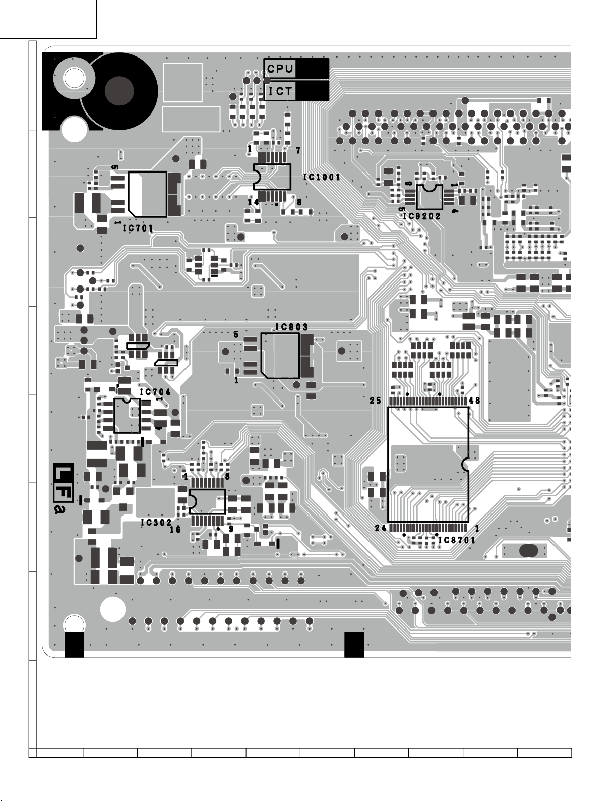
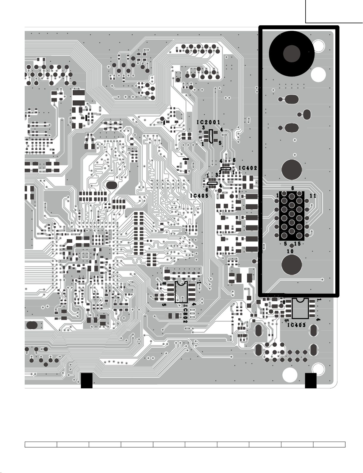
PRINTED WIRING BOARD ASSEMBLIES
SW Unit (Side-A)
SW Unit (Chip Part Side-A)
SW Unit (Side-B)
SW Unit (Chip PartSide-B)
87
Page 88

88
LC-19SK25U/U-W
LC-19SB25U/U-W
LC-19SB15U
LC-19D45U
87 109654321
A
B
C
D
E
F
G
H
MAIN Unit (Side-A)
Page 89

LC-19SK25U/U-W
1716 1918151413121110
LC-19SB25U/U-W
LC-19SB15U
LC-19D45U
89
Page 90

90
LC-19SK25U/U-W
LC-19SB25U/U-W
LC-19SB15U
LC-19D45U
87 109654321
A
B
C
D
E
F
G
H
MAIN Unit (Chip Parts Side-A)
Page 91

LC-19SK25U/U-W
1716 1918151413121110
LC-19SB25U/U-W
LC-19SB15U
LC-19D45U
91
Page 92
92
LC-19SK25U/U-W
LC-19SB25U/U-W
LC-19SB15U
LC-19D45U
87 109654321
A
B
C
D
E
F
G
H
MAIN Unit (Side-B)
Page 93
LC-19SK25U/U-W
1716 1918151413121110
LC-19SB25U/U-W
LC-19SB15U
LC-19D45U
93
Page 94

94
LC-19SK25U/U-W
LC-19SB25U/U-W
LC-19SB15U
LC-19D45U
87 109654321
A
B
C
D
E
F
G
H
MAIN Unit (Chip Parts Side-B)
Page 95

LC-19SK25U/U-W
1716 1918151413121110
LC-19SB25U/U-W
LC-19SB15U
LC-19D45U
95
Page 96

96
LC-19SK25U/U-W
LC-19SB25U/U-W
LC-19SB15U
LC-19D45U
87 109654321
A
B
C
D
E
F
G
H
SUB Unit (Side-A)
Page 97

LC-19SK25U/U-W
1716 1918151413121110
LC-19SB25U/U-W
LC-19SB15U
LC-19D45U
97
Page 98

98
LC-19SK25U/U-W
LC-19SB25U/U-W
LC-19SB15U
LC-19D45U
87 109654321
A
B
C
D
E
F
G
H
SUB Unit (Chip Parts Side-A)
Page 99

LC-19SK25U/U-W
1716 1918151413121110
LC-19SB25U/U-W
LC-19SB15U
LC-19D45U
99
Page 100

100
LC-19SK25U/U-W
LC-19SB25U/U-W
LC-19SB15U
LC-19D45U
87 109654321
A
B
C
D
E
F
G
H
POWER Unit (Side-A)
 Loading...