

Page 1
LC15M4ECover 01/06/13 10:00
LC-15M4E
ENGLISH
LC-15M4E
DEUTSCH
SHARP CORPORATION
OSAKA, JAPAN
LCD AV MONITOR
LCD-AV-MONITOR
MINITEUR AV À
CRISTAUX LIQUIDES
MONITOR AV LCD
MONITOR AV LCD
LCD-BILDSKÄRM
LCD AV-MONITOR
OPERATION MANUAL
BEDIENUNGSANLEITUNG
MODE D’EMPLOI
MANUALE DI ISTRUZIONI
MANUAL DE MANEJO
FRANÇAIS
ITALIANO
ESPAÑOL
SVENSKA
Printed on post-consumer recycled paper.
Gedruckt auf Nachverbraucher-Recyclingpapier.
Imprimé sur du papier recyclé.
Stampato su carta riciclata.
Impreso en papel reciclado.
Tryckt på slutkonsumerat återanvänt papper.
Gedrukt op na-verbruik recycled papier.
Printed in Japan
Japan in Gedruckt
Imprimé au Japon
Stampato in Giappone
Impreso en Japón
Tryckt i Japan
Gedrukt in Japan
TINS-7525CEZZ
BRUKSANVISNING
GEBRUIKSAANWIJZING
NEDERLANDS
Page 2
LC15M4E_CE 01/05/28 16:00
This equipment complies with the requirements of Directive 89/336/EEC and 73/23/EEC as amended by
93/68/EEC.
Dieses Gerät entspricht den Anforderungen der EG-Richtlinien 89/336/EWG und 73/23/EWG mit
Änderung 93/68/EWG.
Ce matériel répond aux exigences contenues dans les directives 89/336/CEE et 73/23/CEE modifiées
par la directive 93/68/CEE.
Dit apparaat voldoet aan de eisen van de richtlijnen 89/336/EEG en 73/23/EEG, gewijzigd door 93/68/
EEG.
Dette udstyr overholder kravene i direktiv nr. 89/336/EEC og 73/23/EEC med tillæg nr. 93/68/EEC.
Quest’apparecchio è conforme ai requisiti delle direttive 89/336/EEC e 73/23/EEC come emendata dalla
direttiva 93/68/EEC.
Η εγκατάσταση αυτή ανταποκρίνεται στις απαιτήσεις των οδηγιών της Ευρωπαϊκής Ενωσης 89/
336/ΕΟΚ και 73/23/EOΚ, %πως οι κανονισµοί αυτοί συµπληρώθηκαν απ% την οδηγία 93/68/ΕΟΚ.
Este equipamento obedece às exigências das directivas 89/336/CEE e 73/23/CEE, na sua versão
corrigida pela directiva 93/68/CEE.
Este aparato satisface las exigencias de las Directivas 89/336/CEE y 73/23/CEE, modificadas por medio
de la 93/68/CEE.
Denna utrustning uppfyller kraven enligt riktlinjerna 89/336/EEC och 73/23/EEC så som kompletteras av
93/68/EEC.
Dette produktet oppfyller betingelsene i direktivene 89/336/EEC og 73/23/EEC i endringen 93/68/EEC.
Tämä laite täyttää direktiivien 89/336/EEC ja 73/23/EEC vaatimukset, joita on muutettu direktiivillä 93/68/
EEC.
SPECIAL NOTE FOR USERS IN THE U.K.
The mains lead of this product is fitted with a non-rewireable (moulded) plug incorporating a 3A fuse.
Should the fuse need to be replaced, a BSI or ASTA approved BS 1362 fuse marked
the same rating as above, which is also indicated on the pin face of the plug, must be used.
Always refit the fuse cover after replacing the fuse. Never use the plug without the fuse cover fitted.
In the unlikely event of the socket outlet in your home not being compatible with the plug supplied, cut
off the mains plug and fit an appropriate type.
DANGER: The fuse from the cut-off plug should be removed and the cut-off plug
destroyed immediately and disposed of in a safe manner.
Under no circumstances should the cut-off plug be inserted elsewhere into a
13A socked outlet, as a serious electric shock may occur.
To fit an appropriate plug to the mains lead, follow the instructions below:
IMPORTANT: The wires in the mains lead are coloured in accordance with the following code:
Blue : Neutral Brown : Live
As the colours of the wires in the mains lead of this product may not correspond with the coloured
markings identifying the terminals in your plug, proceed as follows;
• The wire which is coloured blue must be connected to the plug terminal which is marked N
or coloured black.
• The wire which is coloured brown must be connected to the plug terminal which is marked
L or coloured red.
Ensure that neither the brown nor the blue wire is connected to the earth terminal in your three-pin
plug. Before replacing the plug cover make sure that:
• If the new fitted plug contains a fuse, its value is the same as that removed from the cut-off
plug.
• The cord grip is clamped over the sheath of the mains lead, and not simply over the lead
wires.
IF YOU HAVE ANY DOUBT, CONSULT A QUALIFIED ELECTRICIAN.
or and of
Page 3
Contents
Page
Dear SHARP Customer ......................................1
Important Safety Precautions ........................... 1
Supplied Accessories ........................................3
Preparation .......................................................... 4
Power Connection ......................................... 4
Batteries for Remote Control ....................... 4
Names of Parts (Main Unit) ............................... 5
Names of Parts (Remote Control) .................... 7
Basic Operation ..................................................8
Turning on MAIN POWER .............................8
Switching the AV INPUT [AV1/AV2] Mode .. 8
Sound Volume ................................................ 9
ON/OFF Standby ............................................ 9
Selecting the Menu Items ................................ 10
Adjustment ........................................................ 11
Adjusting the LANGUAGE Settings ........... 11
Adjusting the PICTURE Settings ............... 12
Adjusting the FEATURE Settings .............. 14
Adjusting the SLEEP TIMER Settings ....... 15
Connecting to External Devices ..................... 16
Connecting to a VCR or home video game
system etc. (AV 1/2 IN) ................................ 16
Connecting to a DVD player .......................17
Outputting video and audio
(video output) ...............................................18
Listening with Headphones ........................ 18
Watching TV ................................................. 19
Example of Application ................................... 20
Mounting the LCD monitor on the wall ..... 20
Troubleshooting ............................................... 21
Specifications ................................................... 22
Dimensional Drawings ..................................... 23
Dear SHARP Customer
Thank you for your purchase of the Sharp LCD product. To ensure safety and many
years of trouble-free operation of your product, please read the Safety Precautions
carefully before using this product.
Important Safety Precautions
Page
ENGLISH
Electricity is used to perform many useful functions, but it can also cause personal injuries and property
damage if improperly handled. This product has been engineered and manufactured with the highest
priority on safety. However, improper use can result in electric shock and/or fire. In order to prevent
potential danger, please observe the following instructions when installing, operating and cleaning the
product. To ensure your safety and prolong the service life of your LCD product, please read the following
precautions carefully before using the product.
1. Read instructions—All operating instructions must be read and understood before the product is
operated.
2. Keep this manual in a safe place—These safety and operating instructions must be kept in a safe
place for future reference.
3. Observe warnings—All warnings on the product and in the instructions must be observed closely.
4. Follow instructions—All operating instructions must be followed.
5. Cleaning—Unplug the power cord from the AC outlet before cleaning the product. Use a damp
cloth to clean the product. Do not use liquid cleaners or aerosol cleaners.
6. Attachments—Do not use attachments not recommended by the manufacturer. Use of inadequate
attachments can result in accidents.
7. Water and moisture—Do not use the product near water, such as bathtub, washbasin, kitchen
sink and laundry tub, swimming pool and in a wet basement.
8. Stand—Do not place the product on an unstable cart, stand, tripod or table. Placing the product
on an unstable base can cause the product to fall, resulting in serious personal injuries as well as
damage to the product. Use only a cart, stand, tripod, bracket or table recommended by the
manufacturer or sold with the product. When mounting the product on a wall, be sure to follow the
manufacturer’s instructions. Use only the mounting hardware recommended by the manufacturer.
9. When relocating the product placed on a cart, it must be moved with utmost care.
Sudden stops, excessive force and uneven floor surface can cause the product to
fall from the cart.
10. Ventilation—The vents and other openings in the cabinet are designed for
ventilation. Do not cover or block these vents and openings since insufficient
ventilation can cause overheating and/or shorten the life of the product. Do not
place the product on a bed, sofa, rug or other similar surface, since they can
block ventilation openings. This product is not designed for built-in installation; do
not place the product in an enclosed place such as a bookcase or rack, unless
proper ventilation is provided or the manufacturer’s instructions are followed.
LC-15M4E(01-04)Eng.p65 01.6.15, 4:20 PM1
Page 4
11. Power source—This product must operate on a power source specified on the specification label.
If you are not sure of the type of power supply used in your home, consult your dealer or local
power company. For units designed to operate on batteries or another power source, refer to the
operating instructions.
12. Power cord protection—The power cords must be routed properly to prevent people from stepping
on them or objects from resting on them. Check the cords at the plugs.
13. If you plan to use a 12-VDC power supply unit other than the AC adapter supplied with the
product, make sure the power supply unit provides stable voltage with minimum fluctuations.
Unstable power supply can cause problems in the product.
14. The LCD panel used in this product is made of glass. Therefore, it can break when the product is
dropped or applied with impact. Be careful not to be injured by broken glass pieces in case the
LCD panel breaks.
15. Overloading—Do not overload AC outlets or extension cords. Overloading can cause fire or
electric shock.
16. Entering of objects and liquids—Never insert an object into the product through vents or openings.
High voltage flows in the product, and inserting an object can cause electric shock and/or short
internal parts. For the same reason, do not spill water or liquid on the product.
17. Servicing—Do not attempt to service the product yourself. Removing covers can expose you to
high voltage and other dangerous conditions. Request a qualified service person to perform
servicing.
18. Repair—If any of the following conditions occurs, unplug the power cord from the AC outlet, and
request a qualified service person to perform repairs.
a.When the power cord or plug is damaged.
b.When a liquid was spilled on the product or when objects have fallen into the product.
c. When the product has been exposed to rain or water.
d.When the product does not operate properly as described in the operating instructions.
Do not touch the controls other than those described in the operating instructions. Improper
adjustment of controls not described in the instructions can cause damage, which often requires
extensive adjustment work by a qualified technician.
e.When the product has been dropped or damaged.
f. When the product displays an abnormal condition. Any noticeable abnormality in the product
indicates that the product needs servicing.
19. Replacement parts—In case the product needs replacement parts, make sure that the service
person uses replacement parts specified by the manufacturer, or those with the same characteristics and performance as the original parts. Use of unauthorized parts can result in fire, electric
shock and/or other danger.
20. Safety checks—Upon completion of service or repair work, request the service technician to
perform safety checks to ensure that the product is in proper operating condition.
21. Wall or ceiling mounting—When mounting the product on a wall or ceiling, be sure to install the
product according to the method recommended by the manufacturer.
22. Heat sources—Keep the product away from heat sources such as radiators, heaters, stoves and
other heat-generating products (including amplifiers).
The LCD panel is a very high technology product with 921,600 thin film transistors, giving you fine
picture details.
Occasionally, a few non-active pixels may appear on the screen as a fixed point of blue, green or
red.
Please note that this does not affect the performance of your product.
2
LC-15M4E(01-04)Eng.p65 01.6.15, 4:20 PM2
Page 5
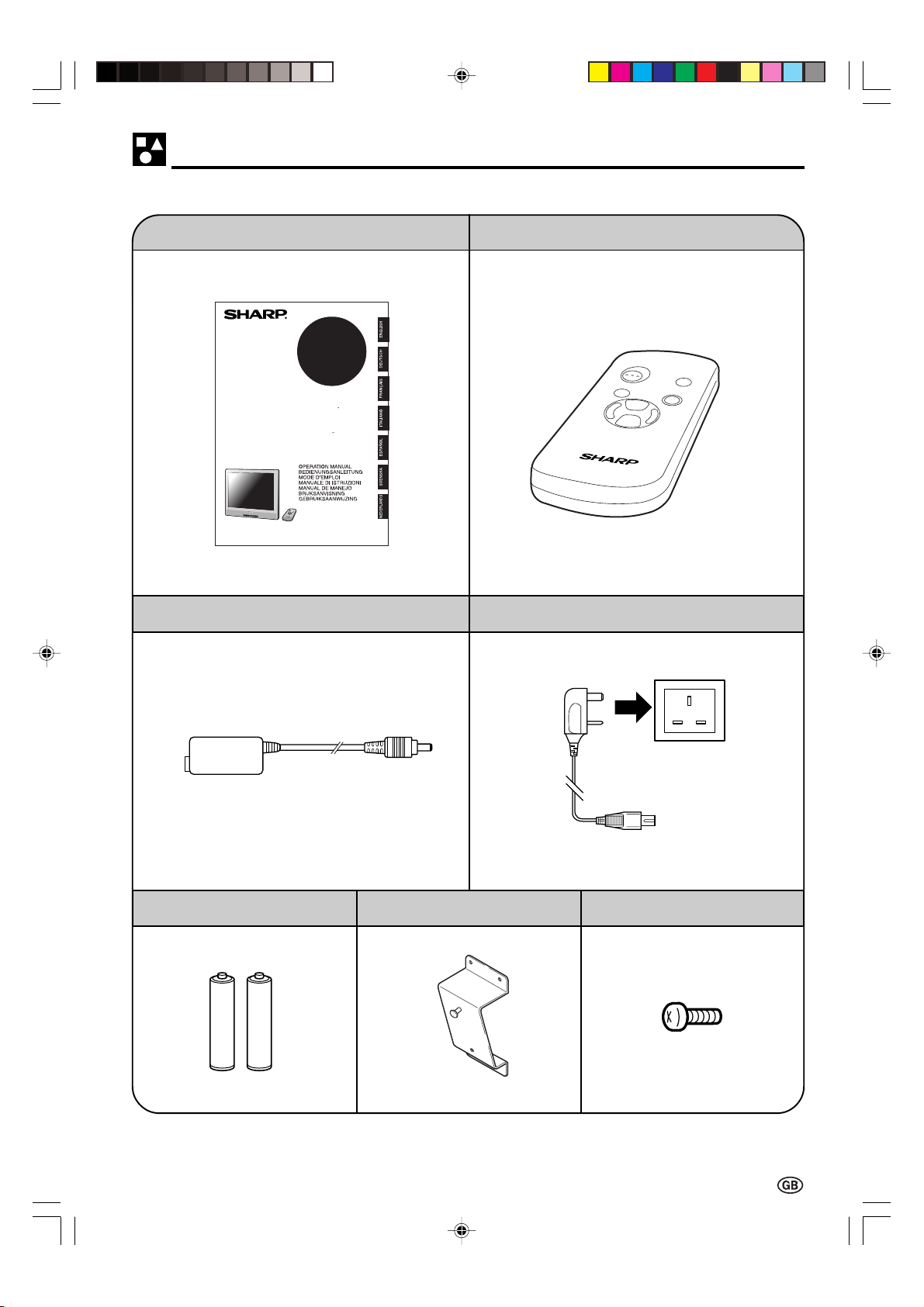
Supplied Accessories
Make sure the following accessories are provided with the product.
Operation Manual (×1) Wireless Remote Control (×1)
LC-15M4E
LCD AV MONITOR
LCD-AV-MONITOR
MONITEUR AV A
CRISTAUX LIQUIDES
MONITER AV LCD
MONITER AV LCD
LCD-BILDSKARM
LCD AV-MONITOR
AC Adapter (×1)
R-03 (UM/SUM-4)
Dry Battery (×2)
* Product shape varies in some countries
Wall Mount Bracket (×1)
AC Cord (×1)
Fixed screw for set stand (×1)
LC-15M4E(01-04)Eng.p65 01.6.15, 4:20 PM3
3
Page 6
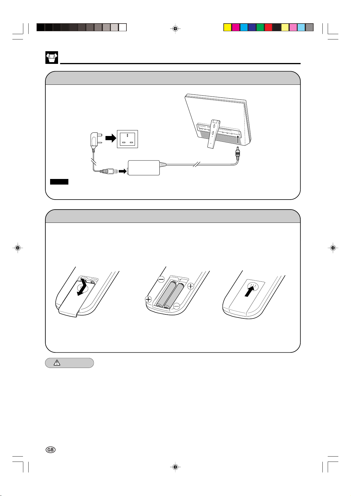
Preparation
Power Connection
Plug into AC outlet.
Household power outlet
AC cord
Notes:
■ Always turn the main power switch of the LCD monitor to OFF when connecting the AC adapter.
■ Always unplug the AC adapter from the product and power outlet when not being used for a long period of time.
AC adapter
Connect to DC input
terminal of the product.
DC input terminal
(12 VDC)
Batteries for Remote Control
If the remote control fails to operate monitor functions, replace the batteries in the remote control.
1 Open the battery
cover.
2 Insert batteries (two R-03
(UM/SUM-4) batteries,
supplied with product).
3 Close the battery
cover.
■ Slide the cover while
pressing down.
■ Place batteries with their
terminals corresponding to
the (+) and (–) indications
in the battery compartment.
Caution!
Cautions regarding batteries
Improper use of batteries can result in a leakage of chemicals and/or explosion. Be sure to follow the
instructions below.
• Place batteries with their terminals corresponding to the (+) and (–) indications.
• Different types of batteries have different characteristics. Do not mix batteries of different types.
• Do not mix old and new batteries. Mixing old and new batteries can shorten the life of new batteries
and/or cause old batteries to leak chemicals.
• Remove batteries as soon as they are non-operable.
Chemicals that leak from batteries can cause a rash. If chemical leakage is found, wipe with a cloth.
• The batteries supplied with the product may have a shorter life expectancy due to storage conditions.
• If the remote control is not used for an extended period of time, remove batteries from the remote
control.
4
LC-15M4E(01-04)Eng.p65 01.6.15, 4:20 PM4
Page 7
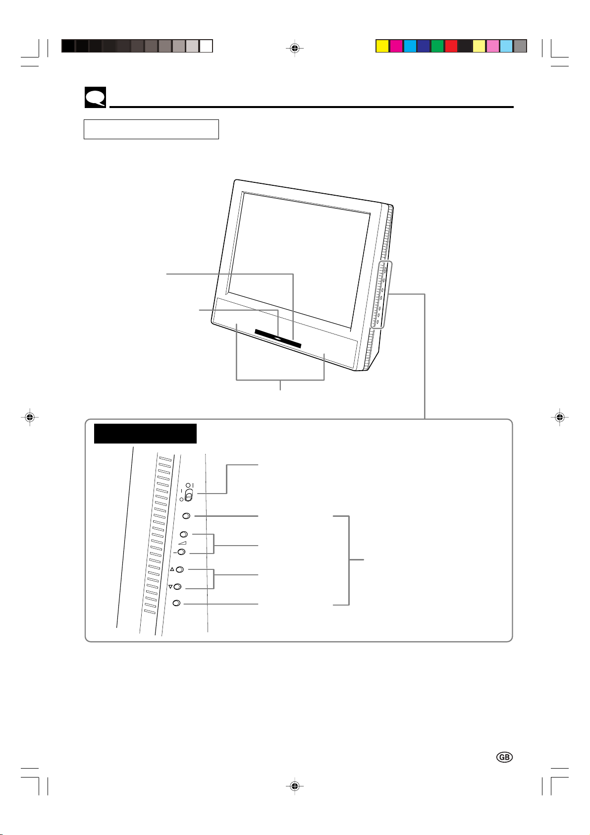
Names of Parts (Main Unit)
Main unit (front view)
Remote sensor
window
Power/Standby
indicator
Side control section
AV INPUT
+
SELECT
MENU
Speakers
MAIN POWER switch
AV INPUT button
Volume (+)/(–) buttons
SELECT (])/([)
buttons
MENU button
The six buttons shown at the left
have the same functions as
those on the remote control.
* When this manual describes
button functions, it is referring
to the buttons on the remote
control.
LC-15M4E(05-10)Eng.p65 01.6.15, 4:42 PM5
5
Page 8
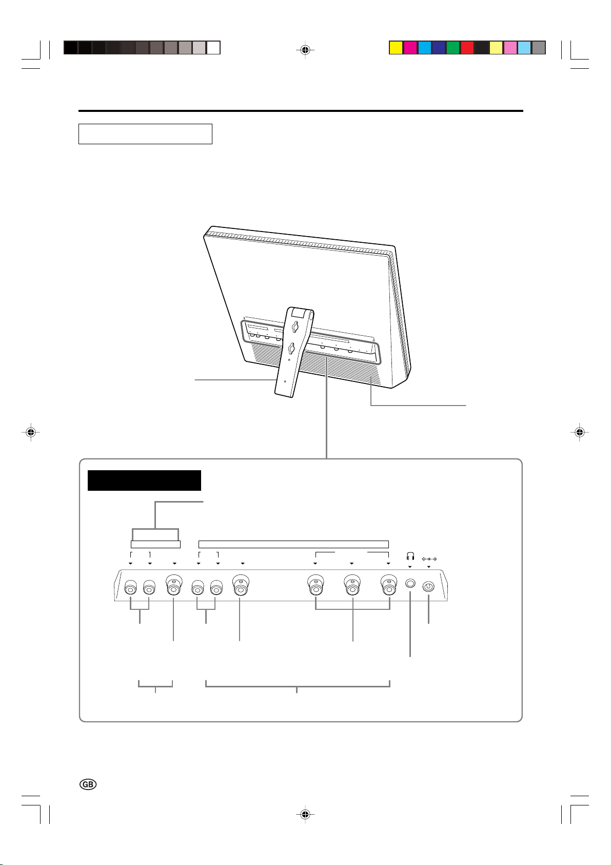
Names of Parts (Main Unit) (Continued)
Main unit (rear view)
Set stand
Rear terminal section
AV 2 IN/OUT
AUDIO VIDEO
R L
AUDIO
VIDEO
VIDEO
Can also be used as video
output terminals.
AUDIO
R L
AUDIO
VIDEO
Rear Speaker
(woofer)
AV 1 IN
COMPONENT
Y P
(
)
C
B
B
(
R
P
POWER
INPUT
DC12V
)
C
R
POWER INPUT
DC12V
COMPONENT
Headphones
AV 1 INAV 2 IN/OUT
6
LC-15M4E(05-10)Eng.p65 01.6.15, 4:42 PM6
Page 9

Names of Parts (Remote Control)
Remote control
Infrared transmitter window
Menu control section
Power ON/OFF
button
AV INPUT
ON/OFF
AV INPUT
SELECT
MUTE
Sound MUTE button
MENU
MENU button
button
SELECT (])/([) buttons
VOLVOL
SELECT
VOL (+)/(–) buttons
LCD MONITOR
■ The side control section of the main unit is also provided with the AV INPUT, SELECT (])/([),
VOL (+)/(–) and MENU buttons.
* When this manual describes button functions, it is referring to the buttons on the remote control.
ON/OFF
AV INPUT
SELECT
LC-15M4E(05-10)Eng.p65 01.6.15, 4:42 PM7
The main power
switch is not
provided on the
remote control.
AV INPUT
MUTE
MENU
VOLVOL
Side control section of main unit
MENU
SELECT
VOLVOL
SELECT
AV INPUT
+
SELECT
MENU
ON/OFF
AV INPUT
MUTE
MENU
SELECT
VOLVOL
SELECT
7
Page 10

Basic Operation
Turning on MAIN POWER
Control section of main unit
1 Slide MAIN POWER, located on the
right side of the main unit, to the
position.
2 The power indicator instantaneously
changes from red to green and the
main unit is turned on.
Notes:
■ When the Power indicator is red, press
ON/OFF on the remote control to turn on
the monitor.
The Power indicator changes from red to
green.
■ The input mode indication disappears after
Power/Standby indicator
five seconds.
Switching the AV INPUT [AV1/AV2] Mode
1 Turn on the power of the connected
video equipment.
2 Press AV INPUT and select the
applicable input source. The screen
displays AV1 or AV2 mode at the
upper right corner each time AV
INPUT is pressed.
ON/OFF
AV/INPUT
ON/OFF
AV INPUT
MUTE
MENU
SELECT
▼ On-screen display
Initial mode (AV1)
AV1
PAL
SELECT
LCD MONITOR
8
LC-15M4E(05-10)Eng.p65 01.6.15, 4:42 PM8
VOLVOL
Note:
■ The AV input mode indication remains for
five seconds.
• AV1: Video equipment connected to the
AV1 input terminals.
The display of the AV1 mode indicates
either AV1 or COMPONENT depending on the adjustment of the FEATURE settings.
AV1 is displayed when AV1 is set to
NORMAL in the FEATURE settings,
and COMPONENT is displayed when
AV1 is set to COMPONENT.
(see page 14)
• AV2: The AV2 mode can be set to either IN
or OUT in the FEATURE settings.
(see page 14)
AV2 indication is not displayed when
the mode is selected to OUT.
AV1 mode
AV1
AV2 mode
AV2
Page 11

VOLUME
10
Sound Volume
VOLUME
30
VOLUME
50
Basic Operation (Continued)
ON/OFF
AV INPUT
LCD MONITOR
SELECT
SELECT
MUTE
MENU
To adjust the volume
Press VOL (+) to increase the sound
MUTE
|
volume. The indicator segment
increases.
VOLVOL
Press VOL (–) to decrease the sound
|
volume. The indicator segment
VOL
decreases.
(+)/( )
To mute the sound
Press MUTE to temporarily turn off the
|
sound.
The MUTE mark
Press MUTE or VOL (+)/(–) to turn the
|
sound back to the previous level.
The MUTE mark
Note:
■ MUTE is automatically cleared when the
following button is pressed: ON/OFF,
VOL (+)/(–) or MUTE.
is displayed.
disappears.
ON/OFF Standby
ON/OFF
AV INPUT
MUTE
MENU
SELECT
SELECT
LCD MONITOR
ON/OFF
VOLVOL
To turn off the LCD monitor
Press ON/OFF.
The power indicator turns red.
To turn the LCD monitor back on
Press ON/OFF again.
The power indicator turns green.
9
LC-15M4E(05-10)Eng.p65 01.6.15, 4:43 PM9
Page 12

Selecting the Menu Items
Selecting the Menu Items
• This LCD monitor set allows you to adjust the picture, sound, and other features using the On-screen
Display. Select the desired menu item by following the steps below and then refer to the indicated page
for details.
ON/OFF
AV INPUT
LCD MONITOR
SELECT
SELECT
MUTE
MENU
VOLVOL
VOL
(+)/( )
MENU
SELECT
(])/([)
1 Press MENU to display the MENU
screen.
2 Press SELECT (])/([) to select
the desired menu item.
• The cursor moves up or down.
• The cursor indicates the selected
menu item.
3 Press VOL (+)/(–) to enter.
4 Press MENU again to exit.
MENU
PICTURE
FEATURE
LANGUAGE
ENTER: –VOL+SELECT: EXIT: MENU
Notes:
■ The displayed items differ depending
on the setting conditions.
■ The selected item is highlighted in
yellow.
■ Items in purple cannot be selected.
■ The original screen is restored by
pressing MENU on the menu screen
or any of the adjustment screens.
The original screen is also restored
when no buttons have been pressed
for about a period of 30 seconds.
The adjustment values and settings
that were changed before the screen
is restored are saved as is in the
memory.
(Pages 12 and 13)
PICTURE(AV1)
CONTRAST
COLOUR
BLACK LEVEL
SHARPNESS
RED-BLUE
GREEN
COLOUR SYSTEM
RESET
[ 30]
[ 0]
[ 0]
[ 0]
[ 0]
[ 0]
[ AUTO]
ENTER: –VOL+SELECT: EXIT: MENU
(Pages 14 and 15)
FEATURE
BRIGHTNESS
AUTO POWER OFF
UPSIDE
RIGHT/LEFT
AV1
AV2 IN/OUT
BLUE BACK
SLEEP TIMER
[BRIGHT ]
[OFF ]
[NORMAL]
[NORMAL]
[NORMAL]
[IN ]
[OFF ]
ADJUST: –VOL+SELECT: EXIT: MENU
(Page 11)
LANGUAGE
ENGLISH
DEUTSCH
NEDERLANDS
FRANÇAIS
ITALIANO
ESPAÑOL
SVENSKA
SELECT: EXIT: MENU
* The screen indications shown above are larger than actual size for easy reading.
10
LC-15M4E(05-10)Eng.p65 01.6.15, 4:43 PM10
Page 13

Adjustment
Adjusting the LANGUAGE Settings
MENU on the LCD monitor set can also be used to select the language.
ON/OFF
AV INPUT
SELECT
SELECT
LCD MONITOR
MUTE
MENU
VOLVOL
VOL
(+)/( )
MENU
SELECT
(])/([)
1 Press MENU to display the MENU
screen.
2 Press SELECT (])/([)
to move the
cursor to LANGUAGE, and then press
VOL (+)/(–)
to display the LANGUAGE
screen.
3 Press SELECT (])/([) to select the
language you want to display.
4 Press MENU againt to exit.
MENU
PICTURE
FEATURE
LANGUAGE
ENTER: –VOL+SELECT: EXIT: MENU
LANGUAGE
ENGLISH
DEUTSCH
NEDERLANDS
FRANÇAIS
ITALIANO
ESPAÑOL
SVENSKA
SELECT: EXIT: MENU
LC-15M4E(11-15)Eng.p65 01.6.15, 4:41 PM11
11
Page 14

Adjustment (Continued)
Adjusting the PICTURE Settings
ON/OFF
AV INPUT
LCD MONITOR
SELECT
SELECT
MUTE
MENU
VOLVOL
VOL
(+)/( )
MENU
SELECT
(])/([)
1 Press MENU to display the MENU
screen.
2 Press SELECT (])/([) to move the
cursor to PICTURE, and then press
VOL (+)/(–) to display the PICTURE
screen.
3 Press SELECT (])/([) to move the
cursor and select the desired
adjustment item.
All items that can be adjusted are
shown in the table on the next page.
4 Press VOL (+)/(–) to display the screen
for the selected adjustment item.
5 Press VOL (+)/(–) to make the
adjustment.
6 Press MENU again to exit.
MENU
PICTURE
FEATURE
LANGUAGE
ENTER: –VOL+SELECT: EXIT: MENU
PICTURE(AV1)
CONTRAST
COLOUR
BLACK LEVEL
SHARPNESS
RED-BLUE
GREEN
COLOUR SYSTEM
RESET
COLOUR
0
– +
[ 30]
[ 0]
[ 0]
[ 0]
[ 0]
[ 0]
[ AUTO]
ENTER: –VOL+SELECT: EXIT: MENU
ADJUST: –VOL+SELECT: EXIT: MENU
12
LC-15M4E(11-15)Eng.p65 01.6.15, 4:41 PM12
Page 15

Adjustment (Continued)
Adjusting the PICTURE Settings (Continued)
Selected item Press VOL (–). Press VOL (+).
CONTRAST Decrease contrast Increase contrast
TINT Toward purple Toward green
COLOUR Lower colour intensity Higher colour intensity
BLACK LEVEL Decrease brightness Increase brightness
SHARPNESS Soft picture Sharp picture
RED-BLUE More red More blue
GREEN Less green More green
COLOUR SYSTEM Press the VOL (+)/(–) to select COLOUR SYSTEM.
Note:
■ TINT is displayed only when N358 or N443 is selected.
Switching the COLOUR SYSTEM
Set the system to AUTO for normal reception. The AUTO mode automatically detects the receiving signal
system and changes the reception system of the set.
When the picture or sound is not stable, switching to an appropriate system may improve the picture or
sound quality.
LC-15M4E(11-15)Eng.p65 01.6.15, 4:41 PM13
13
Page 16

Adjustment (Continued)
Adjusting the FEATURE Settings
The FEATURE items can be set by the user.
1 Press MENU to display the MENU
screen.
2 Press SELECT (])/([) to move the
cursor to FEATURE.
ON/OFF
AV INPUT
SELECT
MUTE
MENU
VOL
(+)/( )
MENU
VOLVOL
SELECT
SELECT
LCD MONITOR
(])/([)
3 Press VOL (+)/(–) to display the
FEATURE screen.
4 Check the factory setting of each item
on the FEATURE screen.
The user can change the settings with
SELECT (])/([) and VOL (+)/(–).
5 Press MENU again to exit.
Selected item Factory setting Setting change
BRIGHTNESS
AUTO POWER OFF
UPSIDE
[BRIGHT] Maximum brightness
[OFF] This feature is
inactivated.
[NORMAL] Normal vertical
image orientation
[MEDIUM] Brightness 60% → Suitable for viewing in well-lit areas.
Saves energy.
[DARK] Brightness 20% → Sufficiently bright when viewing in
dim areas.
[ON] The power of the LCD monitor set is turned off when
there is no signal for 5 minutes.
[DOWN] Inverted image → To display images upside down for
special uses.
MENU
PICTURE
FEATURE
LANGUAGE
ENTER: –VOL+SELECT: EXIT: MENU
FEATURE
BRIGHTNESS
AUTO POWER OFF
UPSIDE
RIGHT/LEFT
AV1
AV2 IN/OUT
BLUE BACK
SLEEP TIMER
ADJUST: –VOL+SELECT: EXIT: MENU
[BRIGHT ]
[OFF ]
[NORMAL]
[NORMAL]
[NORMAL]
[IN ]
[OFF ]
RIGHT/LEFT
AV1
AV2 IN/OUT
BLUE BACK
SLEEP TIMER
[NORMAL] Normal horizontal
image orientation
[NORMAL]
[IN]
[OFF] This feature is
inactivated.
[ – – – REMAIN]
[MIRROR] Mirror image → To display mirror images for special
[COMPONENT]
[OUT
[OUT
[ON] The screen is turned blue when there is no signal.
The setting can be specified in increments of 30 minutes and in a
range between 30 and 120 minutes. (see page 15)
Note:
■ In BLUE BACK, PICTURE setting displayed in purple cannot be selected.
14
ABC
uses.
ABC
ABC
] Line Output is selected, Output volume is fixed, Speaker
output is available.
] Line Output is selected, Output volume is variable,
Speaker output is Mute.
LC-15M4E(11-15)Eng.p65 01.6.15, 4:42 PM14
Page 17

Adjusting the SLEEP TIMER Settings
Adjustment (Continued)
ON/OFF
AV INPUT
SELECT
SELECT
LCD MONITOR
MUTE
MENU
VOLVOL
VOL
(+)/( )
MENU
SELECT
(])/([)
1 Press MENU to display the MENU
screen.
2 Press SELECT (])/([)
to move the
cursor to FEATURE, and then press
VOL (+)/(–)
to display the FEATURE
screen.
3 Press SELECT (])/([)
to move the
cursor to SLEEP TIMER, and then
press VOL (+)/(–) to display the SLEEP
TIMER screen.
4 Press VOL (+)/(–)
to set SLEEP
TIMER (in minutes).
The setting can be specified in
increments of 30 minutes and in a
range between 30 and 120 minutes.
The setting is turned off when --- is
displayed.
5 Press MENU again to exit.
MENU
PICTURE
FEATURE
LANGUAGE
ENTER: –VOL+SELECT: EXIT: MENU
FEATURE
BRIGHTNESS
AUTO POWER OFF
UPSIDE
RIGHT/LEFT
AV1
AV2 IN/OUT
BLUE BACK
SLEEP TIMER
ADJUST: –VOL+SELECT: EXIT: MENU
SLEEP TIMER
– – – REMAIN
ADJUST: –VOL+ EXIT: MENU
[BRIGHT ]
[OFF ]
[NORMAL]
[NORMAL]
[NORMAL]
[IN ]
[OFF ]
Note:
■ If the monitor’s power is turned off and then
turned back on again after the SLEEP TIMER
has been set, the setting will be cancelled.
LC-15M4E(11-15)Eng.p65 01.6.15, 4:42 PM15
15
Page 18

Connecting to External Devices
POWER
INPUT
DC12V
Connecting to a VCR or home video game system etc. (AV 1/2 IN)
This LCD monitor can be connected to most external devices as shown below.
When connecting to an external device, turn off the power of the main unit and then connect to the device
to prevent any possible damage.
To AUDIO/VIDEO
input terminal
Audio/video cord
To audio/video
output terminal
AV 2 IN/OUT
AUDIO VIDEO
R L
Audio
(R)
VIDEO
Audio
(L)
Video
AUDIO
R L
Audio
(R)
Audio
(L)
AV 1 IN
COMPONENT
(
Y P
C
B
To AUDIO/VIDEO
input terminal
VCR connection
cord
To audio/video
output terminal
Video
)
(
B
)
C
R
R
P
AUX 1
AUX 1
TUNER/BAND
TUNER/BAND
AUX 3AUX 2
AUX 3AUX 2
DVD
DVD
SURROUND
SURROUND
ON/OFF
ON/OFF
VCR, Laser disc player, etc. DVD, etc.
* For high quality pictures, a VCR with a
COMPONENT terminal should be connected to the COMPONENT terminal of
the unit. (see page 17)
Notes:
■ PC connection is not possible.
■ Use a commercially available audio/video cord for the cable.
■ When connecting or disconnecting BNC cable to or from the VIDEO input terminal, disconnect the audio cable.
■ Only connect audio/video signals to AV 1 IN and 2 terminals. Connecting other signals may result in a malfunction.
■ Do not connect antennas or headphones to AV 2 IN.
■ For details concerning the usage and connection of external devices, see their respective instruction manuals.
16
LC-15M4E(16-23)Eng.p65 01.6.15, 4:40 PM16
Page 19

Connecting to External Devices (Continued)
POWER
INPUT
DC12V
Connecting to a DVD player
To AUDIO
input terminal
Audio/video cord
To audio
output terminal
AV 2 IN/OUT
AUDIO VIDEO
R L
Audio
(R)
VIDEO
Audio
(L)
AUDIO
R L
Y
P
(CB)
B
To COMPONENT
terminal
VCR connection
cord
To COMPONENT
terminal
P
R
(CR)
AV 1 IN
COMPONENT
Y P
(
)
(
C
B
B
)
C
R
R
P
AUX 1
AUX 1
TUNER/BAND
TUNER/BAND
AUX 3AUX 2
AUX 3AUX 2
DVD
DVD
SURROUND
SURROUND
ON/OFF
ON/OFF
DVD
Note:
■ To view the image from the component connected to the terminals for AV 1 IN, set AV1 to COMPONENT with the
FEATURE setting (see page 14).
LC-15M4E(16-23)Eng.p65 01.6.15, 4:40 PM17
17
Page 20

Connecting to External Devices (Continued)
POWER
INPUT
DC12V
VOLUME
60
Outputting video and audio (video output)
It is possible to output video and audio from the set through the AV output terminals (AV-OUT).
AV 2 IN/OUT
AUDIO VIDEO
R L
VIDEO
AUDIO
R L
AV 1 IN
COMPONENT
Y P
(
)
(
C
B
B
)
C
R
R
P
Connect a VCR, Audio amplifies, etc
Notes:
■ AV2 can be set to input or output. When set to input, output is not possible and vice versa.
■ When using COMPONENT, there is no video output can be made to the AV output terminal, but there is audio output
for connecting to external audio systems.
Listening with Headphones
■ Plug the headphone mini-plug into the headphone jack located on the rear side of the set.
POWER
INPUT
DC12V
▼ On-screen display
Mini-plug
Headphone
jack
Headphones
Notes:
■ The headphones are not included in the supplied accessories.
■ No sound will be heard from the main unit speakers when the headphones are connected.
18
LC-15M4E(16-23)Eng.p65 01.6.15, 4:40 PM18
Page 21

Connecting to External Devices (Continued)
Watching TV
To view a TV broadcast on the LCD monitor, the set-top box must be used with a TV tuner, satellite tuner
or VCR. Refer to the diagram below for wiring.
TV ROOM ANTENNA SET-TOP BOX MONITOR
TERMINAL
TV BROADCAST
(ON AIR)
PAY TV
SATELLITE TV
TV ANT
TV ANT
CABLE
SATELLITE
RF IN VIDEO OUT
VCR
RF IN VIDEO OUT
TV TUNER
RF IN VIDEO OUT
SET TOP BOX
RF IN VIDEO OUT
SATELLITE TUNER
AUDIO
RL
RL
RL
RL
RL
VIDEO
VIDEOAUDIO
VIDEOAUDIO
VIDEOAUDIO
VIDEOAUDIO
(BNC TYPE)
(BNC TYPE)
(BNC TYPE)
(BNC TYPE)
WEB TV
LC-15M4E(16-23)Eng.p65 01.6.15, 4:40 PM19
TV ANT
TEL, LINE
RF IN
Web
SET TOP BOX
VIDEO OUT
RL
VIDEOAUDIO
(BNC TYPE)
19
Page 22

Example of Application
Mounting the LCD monitor on a wall
Note:
■ Consult with your dealer and authorized shop before installation. (Various materials are used for wall. Some materials may not be strong enough or thick enough to hold the mounting screws in place or support the weight of the set.)
1 Mount the supplied wall mount bracket on
the wall with 4 wall mount screws
(commercially available).
Note:
■ Make sure that the screws are suitable for the
particular wall material.
CAUTION: The wall mount bracket must be
installed with 4 screws. Tighten
the screws so that the bracket can
support a weight of at least 20 kg.
2 Mount the back stand of the main unit on the
wall mount bracket with the supplied fixed
screw.
Fixed screw (× 1)
(Supplied)
Wall Mount Bracket (× 1)
(Supplied)
Wall Mount Screw (× 4)
(Commercially available)
■ To mount the LCD monitor at a larger angle for a
business occasion, use the optional bracket such as
the AN-150AG1. This bracket may not be available
in some countries.
* To change the vertical angle of the
monitor, tilt the screen up to 8°
downward. Adjust the angle of the
monitor for the most comfortable
viewing.
Mounting with the optional AN-150AG1
wall mount bracket
20
LC-15M4E(16-23)Eng.p65 01.6.15, 4:40 PM20
Page 23

Troubleshooting
Problem Check item Pages
No image on screen, and
no sound from speakers.
• Make sure that the AC power cord plug is securely
inserted in AC power outlet and AC adapter.
• Make sure that the AC adapter’s DC output is securely
connected to main unit’s DC input terminal.
• Make sure that the main power switch of the main unit is
on.
• Make sure that the AV input is properly set.
• Make sure that the cables are correctly connected to
rear terminal section of LCD monitor.
• Check to see if the batteries in the remote control have
sufficient power.
• Make sure that the unit is not in the standby mode
(power indicator is red).
4
7
7
4
8
Speakers produce sound,
but no image on screen.
Image is too light or
improperly tinted.
Image is displayed, but no
sound from speakers.
• Make sure that the cables are correctly connected.
• Check COLOUR and TINT adjustments. (NTSC ONLY)
• Check CONTRAST and BLACK LEVEL adjustments.
• Check RED-BLUE adjustments.
• Make sure that the VCR connection cord is correctly
connected to the COMPONENT terminal.
• Make sure that the cables are properly connected to
rear terminal section of LCD monitor.
• Check the volume adjustment.
• Make sure that the sound is not muted.
• Make sure that the headphones are not connected.
• Check to see if BRIGHTNESS is set to DARK.
• Check CONTRAST and BLACK LEVEL adjustments.
• Lamp may have reached the end of its life. (Contact a
Sharp service shop for a lamp replacement.)
16, 17
13
13
9
9
18
14
13
Image is too dark.
No colours on image.
Remote control does not work.
LC-15M4E(16-23)Eng.p65 01.6.15, 4:40 PM21
• Check COLOUR adjustment.
• Check the colour system setting.
• Make sure that the VCR connection cord is correctly
connected to P
COMPONENT terminal.
• Check to see if the batteries in the remote control
have sufficient power.
• Make sure that (+) and (–) side of batteries are
properly positioned in remote control.
• Make sure that the remote sensor window is not
under strong fluorescent lighting.
B (CB) and PR (CR) of the
13
13
4
4
21
Page 24

Specifications
ITEM LC-15M4E
LCD Size 15”
Number of dots 921,600 (640 × 3 × 480) dots
Low reflection Non-glare
BRIGHTNESS 450cd/m2 (at normally white)
Viewable angle Left to right 160°
Upper to lower 160°
Life of back light 60,000 hours (at normal mode)
COLOUR System N358/N443/PAL/PAL-M/PAL-N/PAL-60/SECAM
SYSTEM
AUDIO Output 3.4W (0.7W × 2 + 2.0W)
Speaker Full range 3 cm × 4 cm Oval, 2 pcs.
Woofer 6.5 cm Round, 1 pc.
INTERFACES AV 1 IN Audio R/L, Video Composite (BNC TYPE)
(TERMINALS) Component input, Y/PB(CB)/PR(CR)(BNC TYPE)
AV 2 IN/OUT Audio R/L, Video Composite (BNC TYPE)
Headphone jack Mini-jack for stereo
POWER SUPPLY DC operation DC 12V
AC operation AC110~240V with AC adapter
Power consumption 35 W (at maximum brightness)
APPEARANCE Exterior colour Silver
Outside dimensions 357.0 (W) × 309.2 (H) × *62.5 (D) mm
Net weight X.X kg
ACCESSORIES Operation manual language: English/German/French/Italian/
Remote control Infrared wireless type
Wall mount parts Wallmount bracket × 1 pc.
AC adapter Auto-wide type
AC cord #
OSD LANGUAGE Language English/German/French/Italian/Spanish/
31 W (at normal brightness)
Spanish/Swedish/Dutch
fixed screw × 1 pc.
Swedish/Dutch
As a part of policy of continuous improvement, SHARP reserves the right to make design and specification changes for
product improvement without prior notice. The performance specification figures indicated are nominal values of
production units. There may be some deviations from these values in individual units.
* Excluding set stand.
22
LC-15M4E(16-23)Eng.p65 01.6.15, 4:40 PM22
Page 25

Dimensional Drawings
Unit: mm
357
136.7
309.2
16
31
36.6
AV INPUT
SELECT
MENU
62.5
169
POWER
INPUT
DC12V
90°
AUDIO
VIDEO AUDIO VIDEO COMPONENT
RL RL Y PB (CB)PR (CR)
AV 1 INAV 2 IN/OUT
87
LC-15M4E(16-23)Eng.p65 01.6.15, 4:41 PM23
23
Page 26

SHARP CORPORATION
OSAKA, JAPAN
LC-15M4E(16-23)Eng.p65 01.6.15, 4:41 PM24
 Loading...