

Page 1

Version 2.2
R
SHARP Programmable Controller
New Satellite W series
Network module
Remote I/O slave module
User’s Manual
Produced in Oct. 1997
Model Name
JW-20CM
JW-20RS
Page 2
Thank you for purchasing the network module (JW-20CM), remote I/O slave module (JW-20RS) for the
SHARP programmable controller.
Read this manual thoroughly to completely familiarize yourself with the operation according to the
examples.
Besides this manual, the manuals of control module, support tool, and option module are available for the
respective programmable controller.
We ask you to also read these manuals as well as this manual.
Keep this manual for future reference. We are confident that this manual will be helpful whenever you
encounter a problem.
Note
★ This manual describes the JW-20CM, JW-20RS with 30Hn mark in front of the module. The
following functions are added for the JW-20CM and JW-20RS without [30Hn] marks.
① This module can be communicated with JW30H.
② For data link, available for use the following functions.
· Data link (memory capacity save function)
· Data memory start system for SEND/RECEIVE function.
In this manual, additional functions are represented by the V5 mark.
★ In this manual, programmable controller is referred to as “PC.”
★ In this manual, programmable controllers and I/O modules with model name "ZW-xx" are
referred to as "ZW model," and programmable controllers and I/O modules with model name
"JW-xx" are referred to as "JW model."
Note
· This manual is written with the utmost care.
· No part of this manual may be reproduced in any form without permission of SHARP corporation.
· The contents of this manual are subject to change without prior notice.
Page 3

Safety Precautions
Read this manual and attached documents carefully before installation, operation, maintenance and checking
in order to use the machine correctly. Understand all of the machine knowledge, safety information, and
cautions before starting to use. In this instruction manual, safety precautions are ranked into "danger" and
"caution" as follows.
Danger : Wrong handling may possibly lead to death or heavy injury.
Caution : Wrong handling may possibly lead to medium or light injury.
Even in the case of Caution , a serious result may be experienced depending on the
circumstances. Anyway, important points are mentioned. Be sure to observe them strictly.
The picture signs of prohibit and compel are explained below.
: It means don’ts. For example, prohibition of disassembly is indicated as ( ).
: It means a must. For example, obligation of grounding is indicated as ( ).
1) Installation
• Use in the environments specified in the catalog, instruction manual, and user's manual.
Electric shock, fire or malfunction may be caused when used in the environments of high
temperature, high humidity, dusty or corrosive atmosphere, vibration or impact.
• Install according to the manual.
Wrong installation may cause drop, breakdown, or malfunction.
• Never admit wire chips or foreign matters.
Or fire, breakdown or malfunction may be caused.
2) Wiring
• Be sure to ground.
Unless grounded, electric shock or malfunction may be caused.
• Connect the rated power source.
Connection of a wrong power source may cause a fire.
• Wiring should be done by a qualified electrician.
Wrong wiring may lead to fire, breakdown or electric shock.
Caution
Compel
Caution
Page 4

3) Use
• Don’t touch the terminal while the power is being supplied or you may have an electric shock.
• Assemble the emergency stop circuit and interlock circuit outside of the programmable
controller. Otherwise breakdown or accident damage of the machine may be caused by the
trouble of the programmable controller.
•“RUN” or “STOP’” during operation should be done with particular care by confirming safety.
Misoperation may lead to damage or accident of the machine.
• Turn on the power source in the specified sequence. Turning ON with wrong sequence may
lead to machine breakdown or accident.
4) Maintenance
• Don’t disassemble or modify the modules.
Or fire, breakdown or malfunction may be caused.
Danger
Caution
Prohibit
Caution
• Turn OFF the power source before detaching or attaching the module.
Or electric shock, malfunction or breakdown may be caused.
Page 5

■ Configuration of this manual
The network module JW-20CM has three functions: "remote I/O," "data link," and "computer link" functions.
Accordingly, this manual describes about these three functions. Read each section according to your use of
any of these functions.
Users who use the network module for the first time.
Read this manual from chapter 1.
First, thoroughly understanding general, precautions, name and function of each section. Then, read
the contents from chapter 5 for proper use.
Users who want to use the remote I/O function.
Read from chapter 1 to chapter 7 and properly install and connect wiring work of the module. Then set
switches and parameters by referring chapter 8 for correct use.
Switch setting
· Master module: JW-20CM ....... See page 8·9
· Slave module: JW-20RS .......... See page 8·14
Parameter setting
· Master module: JW-20CM ....... See page 8·19
· Slave module: JW-20RS .......... See page 8·30
Users who want to use the data link function (including the computer link function)
Read from chapter 1 to chapter 7 and properly install and connect wiring work of the module. Then set
switches and parameters by referring chapter 9 for correct use.
The module also can function the computer link as data link system with a host computer having a
network module: ZW-98CM/ZW-20AX.
Switch setting
· Master module ............... See page 9·17
· Slave module ................. See page 9·17
Parameter setting
· Master module ............... See page 9·22
· Slave module ................. See page 9·33
Users who want to use only the computer link function
Read from chapter 1 to chapter 7 and properly install and connect wiring work of the module. Then set
switches by referring chapter 10 for correct use.
Switch setting ......... See page 10·3
Users who want to save and load parameter contents using a support tool.
Carefully read the contents of chapter 11 for correct use.
Users who want to add a communication station.
Carefully read the contents of chapter 7 and add a station.
Page 6

Network module JW-20CM
Remote I/O slave module JW-20RS
- User’s Manual -
Chapter 1. Outline
Chapter 2. Safety Precautions
Chapter 3. System Configuration
Chapter 4. Name and Function of Each Part
Chapter 5. Installation
Chapter 6. Processing of Cables
Chapter 7. Wiring
Chapter 8. Remote I/O
Chapter 9. Data Link
Chapter 10. Computer Link
Chapter 11. Support Tools
Chapter 12. Specifications
Chapter 13. Appendix
Page 7

Table of contents
Chapter 1 Outline ................................................................................................................................... 1·1
Chapter 2 Safety Precautions ............................................................................................................... 2·1
2-1 Installation 2·1
2-2 Wiring 2·1
2-3 Treatment 2·3
2-4 Static electricity 2·3
2-5 Maintenance 2·3
Chapter 3 System Configuration .......................................................................................................... 3·1
Chapter 4 Name and Function of Each Part ........................................................................................ 4·1
4-1 JW-20CM 4·1
4-2 JW-20RS 4·3
Chapter 5 Installation............................................................................................................................. 5·1
5-1 JW-20CM 5·1
5-2 JW-20RS 5·4
Chapter 6 Processing of Cables ........................................................................................................... 6·1
6-1 Processing cable end 6·2
6-2 Connector crimping procedure 6·5
Chapter 7 Wiring .................................................................................................................................... 7·1
7-1 Cable trunk and branch lines 7·1
7-2 Relaying of trunk cables 7·1
7-3 Cable wiring procedure in control panel 7·2
7-4 Waterproof and insulation processing of connectors 7·4
7-5 Wiring of cables at outside control panels 7·5
7-6 Check after wiring 7·5
7-7 Wiring method for adding a communication station 7·6
7-8 Wiring to power supply module 7·8
Chapter 8 Remote I/O............................................................................................................................. 8·1
8-1 Description of remote I/O 8·1
8-2 Data transfer required time and communication timing 8·3
8-3 Outline of switch and parameter setting procedure 8·8
8-4 Error and treatment 8·46
Chapter 9 Data Link ............................................................................................................................... 9·1
9-1 Description for data link function 9·1
9-2 Communication method 9·2
9-3 Data transfer required time and communication delay time 9·12
9-4 Expansion of network 9·15
9-5 Switch setting of master station or slave station 9·17
9-6 Setting contents of slave station parameters 9·22
9-7 Setting contents of master station parameters 9·33
9-8 Error and treatment 9·53
Chapter 10 Computer link .................................................................................................................... 10·1
10-1 Description for computer link 10·1
10-2 Computer link function 10·2
10-3 Switch setting 10·3
10-4 Command 10·4
Page 8

Chapter 11 Support Tools ..................................................................................................................... 11·1
11-1 Record and load by ladder software (JW-50SP) 11·1
11-2 Remote function 11·5
Chapter 12 Specifications ....................................................................................................................12·1
12-1 JW-20CM 12·1
12-2 JW-20RS 12·4
Chapter 13 Appendix ........................................................................................................................... 13·1
13-1 Maintenance and check 13·1
13-2 Switch setting table 13·2
13-3 Parameter memory table 13·3
13-4 Address map of data memory 13·20
13-5 Instructions used with the F200 and F201 link function 13·22
13-6 Application instruction using instruction system 13·26
Page 9

Chapter 1 Outline
Using network module JW-20CM, you can construct a communications system (satellite net) which
can easily send and receive an ON/OFF signal (machine information) and numerical data (production
data) between PCs and a host computer using equipment control.
Using remote I/O slave module JW-20RS, you can construct a remote I/O system as master station for
PC that installed JW-20CM.
PCs which can use JW-20CM and JW-20RS are W70H/100H, JW50/70/100, and JW50H/70H/100H.
① Data link/computer link function
This function enables to send and receive ON/OFF signals and numeric data between modules on
a network (satellite net) which is connected PCs and personal computers having network module
ZW-20CM/JW-20CM/JW-22CM, network module ZW-98CM/ZW-20AX, and satellite net board Z335J.
② Remote I/O function
If remote I/O slave module ZW-20RS/JW-20RS are mounted on I/O modules located separately,
one PC having a network module JW-20CM can control these slave modules. (Connectable
maximum 63 modules of slave stations.)
· In the remote I/O function, the remote I/O can choose either of synchronous or asynchronous for
sending and receiving data with slave stations.
Synchronous type: Slave station scans input/output operation one time for each operation of
the PC.
Asynchronous type: When PC's operation time is longer than data transfer required time of the
remote I/O, the slave station scans input/output operation one time for each
operation of the PC. When PC's operation time is shorter than the data
transfer required time of the remote I/O, the slave station operate input and
output one time for several operation of the PC.
1
③ Remote programming/remote monitor function
By constructing a satellite system using the JW-20CM, you can program and monitor other station’s
PC’s (master station’s PC in case that remote I/O function) on the satellite system using a support
tool.
· These remote programming and remote monitor functions are also available beyond one
hierarchical layer difference (satellite net ←→ satellite net, satellite net ←→ SUMINET-3200).
*“SUMINET-3200” is a trademark of Sumitomo Electric Industries, Ltd.
1·1
Page 10
Chapter 2 Safety Precautions
2-1 Installation
● Do not install or store the JW-20CM in the following conditions.
• Direct sunlight
• Ambient temperature exceeding the range of 0 to 55 ˚C (Storage temperature : -20 to 70 ˚C)
• The relative humidity exceeding the range of 35 to 90%.
• Sudden temperature changes which may cause condensation.
• Corrosive or inflammable gas
• Vibration or hard jolts
●Prior to installing or detaching the JW-20CM, make sure to turn OFF the power supply to the PCs.
● All screws must be tightened firmly.
2-2 Wiring
● Make sure to use only the recommended types (see page 6 · 1) for cables, connectors, and crimping
tools.
2
●When using connectors for branch or joint lines, provide jackets to protect connectors.
(When a connector touches with an external enclosure or the like, a communication error may occur.)
“T” jacket
(insulation cover)
“L” jacket
(insulation cover)
● Do not connect the ground terminal of the power supply module together with other equipment’s
ground lines. Make sure to provide class-3 grounding.
When the JW-20CM is used without connecting a class-3 grounding, malfunctions by noise may
occur.
● Communication cables should be arranged as far from any high voltage lines and strong power lines
as possible. Do not lay the communication cable parallel or proximate to these lines.
2·1
Page 11

● Communication cables should be laid from the master station to the slave station one by one.
Multiple wiring from one point or wiring without terminators may cause communication errors.
Joint using a
connector
2
● Arrange total cable length within 1 km.
● Arrange branch cable line from a trunk within 400 mm.
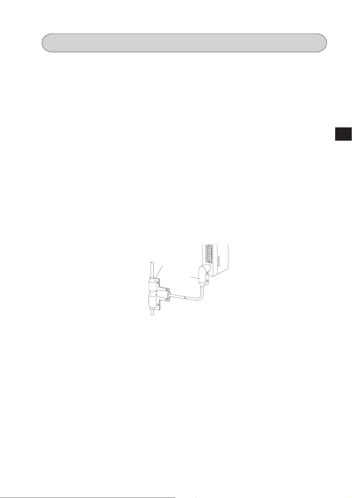
● Prior to any electric welding around the JW-20CM, take out the coaxial cable from the JW-20CM.
While the coaxial cable is connected to the JW-20CM, any electric welding nearby the JW-20CM will
cause the welding current to enter the JW-20CM and may damage part of its circuit pattern.
JW-20CM
Turn “ON”
shield ground
FG
Note: In case enough
conductivity is not
established.
Coaxial cable
Wraparound current
Electric welder
JW-20CM
JW-20CM has a
fuse element here
Turn “ON”
shield ground
FG
Rack etc.
2·2
Page 12

2-3 Treatment
● For ventilation, holes are provided in the cabinet to prevent a temperature rise. Do not block the
ventilation holes. Good ventilation is necessary.
● Never allow a liquid such as water and chemical solution and a metallic object like a copper wire
inside the JW-20CM to avoid a possible hazard. Otherwise, it may be a cause of machine trouble.
● When a trouble or abnormal condition such as overheat, fume, or smoke is met, stop the operation
immediately, and call your dealer or our service department.
2-4 Static electricity
In extremely dry circumstances, the human body may have excessive static current. This excessive
static current may damage parts in the JW-20CM’s PC board. Therefore, prior to accessing the JW20CM, touch your hand to a grounded piece of metal to discharge the static current in your body.
2-5 Maintenance
Use a clean, dry cloth when cleaning the JW-20CM. Do not use volatile chemicals such as thinner or
alcohol as it may result in deformation and color fading.
2
2·3
Page 13

Chapter 3 System Configuration
(Example of system configuration)
Personal computer
(8)
Slave station
(8)
03
J-board
Z-335J
V5
Master station 00
JW-20CM
PC
(8)
Slave station 01
JW-20CM
PC
slave station 02
(8)
Network module
JW20
JW20H
JW30H
Slave station 77
JW-22CM
(8)
3
Data link system
Compuer link system
Slave station 01
JW-20RS
(64 stations max., Total extension length: 1km max.)
(8)
Slave station 02
(8)
ZW-20RS
Remote I/O system (slave station : 63 stations max., Total extension length: 1km max.)
“PC” indicates W70H/100H, JW50/70/100, and JW50H/70H/100H.
Slave station 77
JW-20RS
(8)
3·1
Page 14

Chapter 4 Name and Function of Each Part
4-1 JW-20CM
①
②
③
④
⑤
⑥
① Indication lamps
Lamps light ON/OFF indicates operation condition.
JW–20CM
C O M M ○
S D ○
R D ○
C D ○
L T ○
T E S T ○
E R R O R ○
F A U L T ○
30Hn
○ S 0
○ S 1
○ S 2
○ S 3
○ S 4
○ S 5
○ S 6
○ S 7
emaN noitarepO
MMOCgnitacinummocgnirudsthgiL
DSgnidnesatadnehwsthgiL
DRgnivieceratadnehwsthgiL
DCreirracgnitcetednehwsthgiL
TLecnatsisernoitanimreteht"NO"gninrutnehwsthgiL
TSETgnitsetgnirudsthgiL
RORRErorrenoitacinummocatasthgiL
⑦
4
(View removing the cover on the setting section)
TLUAFremitgodhctawehtfopuemittasthgiL
0S ot 7S.sruccororrenehwedocrorresthgiL
② 30Hn mark (Applied to JW30H)
JW-20CMs having 30Hn mark can communicate with JW30H.
JW-20CMs having 30H can communicate with conventional modules of JW30H (JW-31CUH/32CUH/
33CUH). However, when they will communicate with new modules of JW30H (JW-31CUH1/32CUH1/
33CUH1/33CUH2/33CUH3), they recognizes these new modules as conventional modules.
4·1
Page 15

③ Support tool connection connector
Connect a support tool and set parameter etc.
④ Setting switch
Set functions of JW-20CM.
Set at delivery
D
C
E
B
A
F
9
0
8
MODE
STA.NO.
×10
×1
LT
(ON)
4
LG
(ON)
1
7
6
3
5
4
8
7
6
5
4
2
3
8
7
6
5
4
2
3
0
2
9
0
1
0
9
0
1
0
OFF
ON
· MODE switch .... Select functions
rebmuN noitcnuF
0yreviledtateS
1O/IetomeR
2
knilretupmoC
3
knilretupmoC
Fot4.testonoD
·S T A . N O.
××
× 10,
××
××
× 1
××
.... Set station number
)noitcnufdradnats(knilataD
)noitcnufevasyticapacyromem(knilataD
·L T .... Set ON/OFF of termination resistance
·L G .... Set shield ground ON/OFF of communication cable
⑤ Communication cable connection connector
BNC type receptacle (jack)
⑥ Connector protective cap
⑦ Rating plate
4·2
Page 16

4-2 JW-20RS
①
②
③
④
⑤
⑥
① Indication lamps
Lamps light ON/OFF indicates operation condition.
JW–20RS
C O M M ○
S D ○
R D ○
C D ○
L T ○
T E S T ○
E R R O R ○
F A U L T ○
30Hn
○ S 0
○ S 1
○ S 2
○ S 3
○ S 4
○ S 5
○ S 6
○ S 7
emaN noitarepO
MMOCgnitacinummocgnirudsthgiL
DSgnidnesatadnehwsthgiL
DRgnivieceratadnehwsthgiL
DCreirracgnitcetednehwsthgiL
TLecnatsisernoitanimreteht"NO"gninrutnehwsthgiL
TSETgnitsetgnirudsthgiL
RORRErorrenoitacinummocatasthgiL
⑦
4
TLUAFremitgodhctawehtfopuemittasthgiL
0S ot 7S.edocrorresetacidnI
② 30Hn mark (Applied to JW30H)
JW-20RSs having 30Hn mark can communicate with JW30H.
JW-20RSs having 30H can communicate with conventional modules of JW30H (JW-31CUH/32CUH/
33CUH). However, when they will communicate with new modules of JW30H (JW-31CUH1/32CUH1/
33CUH1/33CUH2/33CUH3), they recognizes these new modules as conventional modules.
4·3
Page 17

③ Support tool connection connector
Connect a support tool and set parameter etc.
④ Setting switch
Set functions of JW-20RS.
Set at delivery
D
C
E
B
A
F
9
0
8
MODE
STA.NO.
×10
×1
LT
(ON)
4
LG
(ON)
1
7
6
5
4
8
7
6
5
4
3
8
7
6
5
4
3
2
2
3
9
0
1
0
2
9
0
1
0
2
OFF
ON
· MODE switch .... Select functions
rebmuN noitcnuF
0.testonoD
1)O/I-WZ(O/IetomeR
2)O/I-WJ(O/IetomeR
Fot3.testonoD
·S T A . N O.
××
× 10,
××
××
× 1
××
.... Set station number
·L T .... Set ON/OFF of termination resistance
·L G .... Set shield ground ON/OFF of communication cable
Output hold
switch
HOLD
RST
⑤ Communication cable connection connector
BNC type receptacle (jack)
⑥ Connector protective cap
⑦ Rating plate
⑧ Output hold switch
Set the status of the output module when the JW-20RS stops operation.
Output hold
※
switch ⑧
HOLD
RST
·In case of using ZW-I/O
HOLD: Holds operation condition
RST: All points is OFF
· In case of using JW-I/O
Be sure to setting at HOLD.
Keep the switch marked with ※ as the setting at delivery (condition in the figure above).
4·4
Page 18

Chapter 5 Installation
5-1 JW-20CM
(1) Installation of cable for option module
Install the optional cable on the basic rack panel that installed JW-20CM.
emaneludomCP
H07WBK82-WZCC2-WZ
ledomWZ
H001WBK64-WZCC4/CC2-WZ
05WJBK82-WZCC2-WZ
07WJBK64-WZCC4/CC2-WZ
001WJUB4-WJCC2-WZ
ledomWJ
H05WJUB6-WJCC4/CC2-WZ
H07WJUB8-WJCC6/CC4/CC2-WZ
H001WJUB31-WJCC6/CC4/CC2-WZ
In case that install a basic rack panel JW-4BU to ZW-2CC
① Bend the optional cable
lenapkcarcisaB
emanledom
noitporofelbaC
eludom
O/IgnisurofelbaliavA
ledomWZfoeludomO/I
ledomWJfoeludomO/I
5
Basic rack panel face
Install the cable in a manner
that it may be slack towards
the rack panel.
5·1
Page 19

② Attach the connectors in the optional cable one after another, starting from the left side.
Basic rack panel
JW-4BU
Pay close attention to the
installation of the connector.
Cable for
option module
ZW-2CC
5
6 mounting screws
(Attached to cable for
option module)
5·2
Page 20

(2) Installation of JW-20CM
Attach the basic rack panel using the two attachment screws.
Before installation or removal, make sure to shut OFF the power supply to the PC.
(Example) Install on basic rack panel JW-4BU
· This module can be installed in any one of the optional slots.
· Be careful not to bend the connector pins on the module by applying too much force to them.
Module
Basic rack
panel
Phillips
screwdriver
· More than one modules of JW-20CM can be installed on one basic rack panel. However they
cannot communicate by crossing-over another network.
Unavailable
communication between
A and C.
Available communication
between A and B, B and
C, B and B, and C and C.
station
Master
A
5
Slave
station
Slave
station
Master
Station
B
C
Slave
station
C
Slave
station
Slave
station
Master
Station
B
C
Slave
station
C
· Optional slots have each port numbers. When an error occurs, the JW-20CM stores the port
number corresponding to the error occurred module into system memory #050 in the PC. This is
applied only error code 53: Optional error.
(Ex.: JW-13BU)
Control module
②③④ ⑤⑥ ⑦
▲
Port number
5·3
Page 21

5-2 JW-20RS
Choose type of basic rack panel of the remote I/O slave module (JW-20RS) considering kinds and
number of I/O modules to be installed.
seludomO/IfosdniK emanledomlenapkcaR
)seludom8rof(UB80-WZ
ledomWZfoeludomO/I
ledomWJfoeludomO/I
When I/O modules for JW model are used, maximum two modules of basic rack panel can be connected
per one remote I/O slave module. However, I/O bus expansion adapter (JW-1EA/JW-2EA) cannot be
used.
)seludom4rof(BK40-WZ
)seludom2rof(BK20-WZ
)seludom4rof(UB4-WJ
)seludom6rof(UB6-WJ
)seludom8rof(UB8-WJ
)seludom31rof(UB31-WJ
5
2 rack panel max.
5·4
Page 22

(1) Installation of power supply module
Attach the end left of rack panel using the two module attachment screws.
Module attachment screw hole
Phillips screwdriver
Output connector
5
Phillips screwdriver
Module attachment screw hole
Rack panel attachment screw
5·5
Page 23

(2) Installation of JW-20RS
Install the JW-20RS in the second slot from the left end using the two module attachment screws.
Before installation or removal, make sure to shut OFF the power supply to the PC.
Module attachment
screw hole
Power supply module
Phillips screwdriver
5
JW-20RS
5·6
Page 24
Chapter 6 Processing of Cables
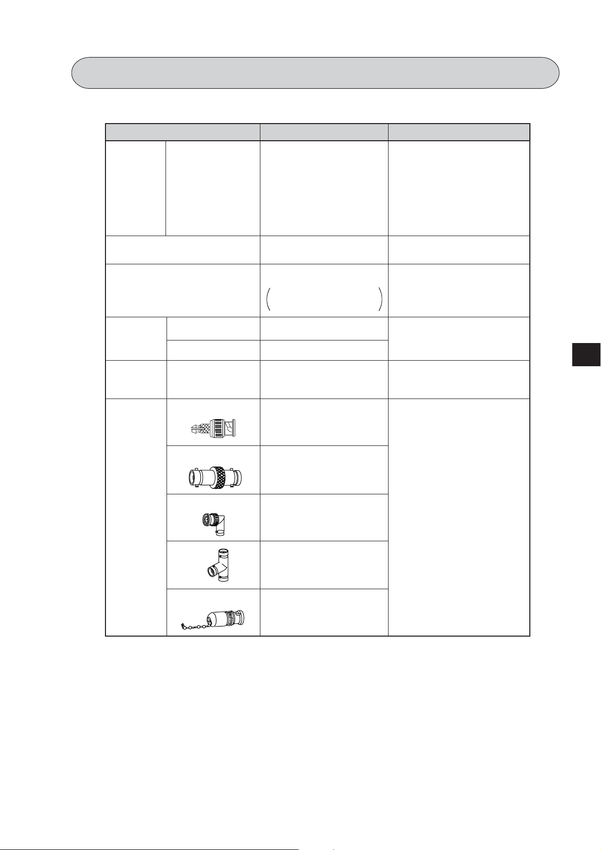
Make sure to use the recommended models shown below for cables and connectors.
Name
Cable
Crimping tools
Stripper for high frequency
Jacket
Insulation
tape
High frequency
coaxial cable
coaxial cable
“L” jacket
“T” jacket
Self-adhesive tape
Connector
Model
ME-5C-2V
ME-42H
Dice: 67-42H
CST-TM
The system consists of the
main body, a blade cassette,
and a blade setting gauge
SB-2878
SB-2879
NO.11
ME-GP-01
Maker
Mitsubishi Cable
Industries,. Ltd.
Fujikura Cable,. Ltd.
Furukawa Denko
Corporation
Chugoku Cable,. Ltd.
Shinagawa Cable,. Ltd.
Toko Denshi Corporation
Nihon Weidmüller
Co., Ltd.
Shinagawa Shoko
Co., Ltd.
6
Nitto Denko
Corporation
Connectors
Straight
Elbow
T’s
Termination
ME-JJ-01
Toko Denshi Corporation
ME-LA-01
DDK Ltd.
ME-TA-01
ME-75
6·1
Page 25

6-1 Processing cable end
① Applicable cable
High frequency coaxial cable: ME-5C-2V
② Required tools
Stripper for high frequency coaxial cable: CST-TM
③ Processing procedure
<Basic operation>
Move the cam wheel of the stripper (amber colored
Cable holder
ring) back and forth and the cable holder moves back
and forth accordingly. Confirm this movement of the
stripper first.
To hold the stripper, put your forefinger through the
hole and move the cam while pushing back and forth
with your thumb.
<Pressure setting>
Set the operation range of the cable holder by moving
6
the slider at the bottom of the body. Move to the left
to increase pressure.
Blade cassette
In this example, set the slider to the cam wheel side’s
end (right side) to set the pressure to low.
Front
Blade (slashed area)
Cam wheel
Rear
<Adjustment of blade cutting depth>
Adjust the cutting depth of the blade by turning the
two screws at both ends of the screw holder. Set
the blade position to within 1 mm from the cutting
surface of the blade cassette prior to adjusting the
cutting depth. For the cutting depth adjustment, use
the “blade setting gauge” supplied as an accessory
and match the blade position with the caved position
of the gauge. Then move the cam wheel forward
and secure firmly. Turn right lightly both adjustment
screws at either end of the screw holder for
adjustment. (Be careful not to break the blade setting
gauge as it is made of aluminum.)
(Fine adjustment is required to get the
optimum cutting depth.)
To the next page
Left
Slider
Screw holder
Within 1 mm
Set the blade to within
1 mm in order not to
damage the blade by
the blade setting gauge.
Cam wheel
Right
Blade setting gauge
6·2
Page 26

Coating
(black)
External conductor
(meshed annealed copper wire)
From the previous page
<Cutting of coating, external conductor,
and insulator>
Put a coaxial cable while remaining approximately 10 mm into
the cable stripper and securely tighten the cable with the middle
finger, ring finger, and little finger of your left hand in order to
hold stable during turning the stripper.
Put your right hand forefinger into the cam wheel and execute
the procedure in order from step 1 below.
Internal conductor
(annealed copper single wire)
Insulator
(semi-transparent)
While holding the coaxial cable with your left hand, grip the
cable stripper so that it keeps a right angle against the coaxial
cable, and press out the cable stripper with your left hand’s
thumb.
When the adjustment
of the blade is not
required
Step 1
Press the cam wheel forward 3 times and turn
the stripper in the direction of arrow 2 to 3
times.
Step 2
Press the cam wheel forward 1 time and then
turn the stripper in the direction of arrow a
further 2 to 3 times.
Step 3
Press the cam wheel forward 1 more time and
turn the stripper in the direction of the arrow
another 2 to 3 times.
<Removal of coating, external conductor,
and insulator>
If the stripper cannot be removed smoothly,
adjustment of the blade is not appropriate. In this
case slide the cam wheel backward and remove
the coaxial cable. Then adjust the blade.
10
mm
6
<Fine adjustment of blade cutting depth>
When the cutting depth is too shallow or too deep, and
damages the external conductor or the internal conductor, turn
the screws on the screw holder and adjust the blade depth a
little.
To the next page
6·3
Page 27

From the previous page
<Display of blade setting>
We recommend that in order to keep the adjusted
position of the adjustment screws, after completion
of adjustment for the coaxial cable and the screw
holder, write the screw position etc. on a sticker
and adhere it to the adjustment screws.
K
A
E
C
A
A
D
A
A
D
F
S
F
G
H
H
G
KADAEA
KEDAADFS
<Replacement of blades>
Hold up the upper section of the screw holder with
Blade cassette
a minus driver, and open the screw holder.
Remove the blade cassette and reinsert by turning
the current blade back side front or insert a new
blade cassette from its top.
Screw holder
6
<Processing of cable end>
Cut the internal conductor of the coaxial cable,
which is already cut by the stripper, using a nipper
etc. to the optimum dimension of 4 mm.
10 mm±0.5 mm
BA
A: 10±0.5 mm
B: 4±0.5 mm
6·4
Page 28

6-2 Connector crimping procedure
9
.
1
.
TT-237
TT
237
① Required tools: Hand-held crimping tool
Model
Dice No.
Crimping width
: ME-42H
: 67-42H
: 10 mm
② Connector: ME-GP-01
③ Processing procedure
<Insert a sleeve>
Put through a sleeve to an end-processed high
frequency coaxial cable.
<Crimping contact>
Insert a contact into the internal conductor and crimp.
Sleeve
Connector parts
Contact
A: 10±0.5 mm
B: 4±0.5 mm
Shell
A
Sleeve
B
6
Put a contact into dice having a
diamond shape and closely stick its
end surface with the insulator and the
dice. Pull the moving frame to the
fixing frame side and crimp until the
ratchet is removed.
(Crimping width: 2.2 mm)
Widen a little
Crimp
Dice blade shape
2.2 mm
Closed contact
* Use the crimping tool in the direction
shown in the illustration right.
Using the crimping tool in the reverse
direction will not crimp correctly.
Internal conductor
Crimping dice
Moving frame
Insulator
Crimping dice
-
TT
237
9
.
.
1
Contact
Fixing frame
Contact
Closed
contact
To the next page
6·5
Page 29

From the previous page
TT
237
<Fixing the connector>
Slightly widen the external conductor of the
coaxial cable, which is crimped to a contact on
the internal conductor, in order to smoothly enter
the shell inside the external conductor. Press in
the external conductor end of the coaxial cable
to just before the crimping part of the shell and
put the sleeve into the crimping section. Then
press in the coaxial cable until a “click” sound
can be heard. Confirm that the contact end point
touches your finger cushion.
Widen a little
Sleeve
Shell
Crimping section
Finger
<Crimping external conductor>
Crimp the external conductor.
Completely put into
the crimping section.
Insert thoroughly the sleeve into the
crimping section of the shell and crimp.
Put the sleeve in the hexagonal dice
and closely stick the shell to the
crimping dice. Pull the moving frame
6
to the fixing frame side while pressing
the coaxial cable and shell from both
10
Dice blade shape
sides, and crimp until the ratchet is
removed.
(Crimping width: 10 mm)
Dice blade shape
looking from this side
Crimping dice
Push
Closed contact
* Use the crimping tool in the direction
shown in the illustration right.
Using the crimping tool in the reverse
direction will not crimp correctly.
-
TT
237
9
.
.
1
Insulation test of shell and contact
Using a tester, check the conductivity
between the internal conductor and
the external conductor in the
connector. When the indication of
the tester shows ∞ ohms, the
insulation is appropriate.
Conductivity test
After short-circuiting the one end
of the connector crimped to the
coaxial cable, check that
conductivity is attained.
<Insulation test>
<Conductivity test>
6·6
Page 30

Chapter 7 Wiring
7-1 Cable trunk and branch lines
① On the illustration of the cable wiring below, a bold line means a trunk and the thin lines branched
from the trunk with a “T” shape are called branch lines.
Branch line
400 mm max.
Trunk cable
② The length of branch lines branched from the trunk should be within 400 mm.
400
mm
③ Total cable length should be within 1 km.
Branch line
Trunk cable
7-2 Relaying of trunk cables
① To relay trunk cables, use the straight joint (ME-JJ-01).
ME-JJ-01
② Relaying of trunk cables should be limited to indispensable cases only. Inadvertent relaying of
trunk cables may cause a communication fault such as a weakened signal level due to contact
resistance in the junction connector (straight).
7
Junction
Junction
7·1
Page 31

7-3 Cable wiring procedure in control panel
[1] Fixing of the cable
In order not to put any force on the cable and the
JW-20CM, fasten the cable to an line nearby input
of a control panel or a “T” branch point to the JW20CM using saddles etc.
[2] Extra length of cable
Provide an extra length of the cable of 2 to 3 m
inside a control panel for easier processing of the
cable end and easier wiring when changing module
positions.
Saddle
JW-20CM
Saddle
Anextralengthof
cableof2to3m
[3] Connection to the JW-20CM
The connector to the JW-20CM should be turned
Communication cable
connection connector
right to secure locking, not merely inserted.
7
[4] Insulation cover
When the connector touches with a high voltage
section or external enclosures, communication
errors may occur. Make sure to install an insulation
cover.
“T” jacket
(insulation cover)
“L” jacket
(insulation cover)
7·2
Page 32

[5] Grounding of power supply module
Make sure to connect the GND terminal of the power supply module to a class-3 grounding.
• If the power supply module is not grounded, the JW-20CM cannot conduct with the ground after
turning “ON” the shield ground switch.
In case of AC power supply module (JW-1PU)
Power supply module (JW-1PU)
SHORT
Class-3
grounding
200 VAC
SHORT
100 VAC
INPUT
AC/AC
100V 200V
GND
HALT
OUTPUT
Detail of the terminal block
Input power voltage
switching terminal
Power input
terminal
GND (ground)
terminal
Halt signal
output terminal
7
7·3
Page 33

7-4 Waterproof and insulation processing of connectors
In order to prevent water intrusion into the “T” branch connectors and the straight connectors, we
recommend to wind a self-adhesive tape and provide waterproof processing for them. For insulation
purposes, cover these connectors with jackets.
[1] “T” branch connector
To wind a self-adhesive tape, cut the tape at about 10 cm each and start winding from position ①.
Start winding cut tapes from ② and ③ as well.
②
①
T’s
7
[2] Straight connector
To wind the self-adhesive tape, cut the tape at about 15 cm each and start winding from position ① .
①
Self-adhesive tape
③
Self-adhesive tape
Straight
Remarks
Prior to adhering the tape, clean the surface of the connectors and stick the adhesive side of
the tape on the connector surface. Wind to lightly spread on the connector surface, and overlap
with the next wrap to half of the tape width. Wind the tape for each wrap evenly so that the
connector metal portion is completely covered with the tape.
Be careful not to excessively stretch the tape.
7·4
Page 34

7-5 Wiring of cables at outside control panels
① Do not bundle the coaxial cable (the trunk and branch lines) together with power cables, and
separate from power cables at least by 100 mm. Do not put the coaxial cable into a power line wired
duct. The best way is to put the communication line in an independent duct.
② Be careful that the coaxial cable does not receive any load by laying under a heavy weight such as
other cables.
When other cables run in the same duct as the coaxial cable, run the coaxial cable on the top
position.
③ Do not run the coaxial cable outdoors as it may cause damage to the JW-20CM due to inductive
lightning or atmospheric charge during lightning.
7-6 Check after wiring
Check the items below after completion of wiring.
1
The recommended connector types are used.
2
The connectors are securely locked.
3
The connectors are insulated by T jacket or L jacket.
4
The recommended coaxial cable type is used.
5
Curved radius of the coaxial cables are more than 45 mm.
6
No heavy load is on the coaxial cables.
The coaxial cable is not bundled with a power line cable.
7
(Away from power line cables more than 100 mm.)
8
Length of branch lines is shorter than 400 mm.
9
Total length of the cable is less than 1 km.
Settings of the termination resistance switch and the shield ground switch are as per
10
the drawings.
Check contents
7
7·5
Page 35

7-7 Wiring method for adding a communication station
[1] Branching method
When branching a line for an additional station, be sure to branch from the trunk using a T connector.
Never branch from a branch line.
Station number
(8)
Station number
(8)
0 2
Station number
(8)
0 3
Station number
(8)
0 2
0 6
Trunk
cable
Station number
(8)
0 3
Trunk
cable
Branch
line
Addition
Station number
(8)
0 2
Station number
(8)
0 6
Junction
Station number
0 3
(8)
Branch line
[2] Station number of the additional station
Station number of the newly added station should be next largest number from the current largest
7
numbered station. Each station should not be required to be arranged in order of each station’s
number.
01(8)
02(8)
03(8)
04(8)00(8)
05(8)
Addition
Sequential number
00(8)
01(8)
02(8)
03(8)06(8)
means the termination resistance switch being turned “ON.”
7·6
04(8)
05(8)
Page 36

[3] Notes
When adding a communication station, follow the items below.
Item No.
Branch from the trunk cable.
1
Don’t use the same station number
2
twice.
Check the termination resistance
3
switch.
Provide extra length for the
4
expansion cable.
Do not exceed the 1 km limit for total
5
length of the cable.
Change the layout drawing for
6
installation.
Do not overlap with any PC’s
7
communication area.
Set the parameter memory of the
master station and that of the newly
8
added station.
Reason
Another branch line from a branch line may not give
appropriate communication by reflection wave.
The use of the same station number twice may cause
communication errors.
When the newly added station becomes a termination of
the circuit, change the setting of the LT switch.
Have enough cable length in order to provide easy wiring.
Longer wiring may cause communication error by signal
attenuation.
Maintain the added work data for future maintenance use.
When the communication area or the flag area of the
added station overlaps with other addresses in use,
communication errors may occur.
Without setting the parameter memory of the master
station and that of the slave station, the added station
cannot communicate.
7
7·7
Page 37

7-8 Wiring to power supply module
[1] JW-1PU
· Open the terminal block cover, fasten with the screw with torque of less than 12kg·cm.
·A maximum of three halt output lines can be connected serial. To use more than three sets, use
a relay for interconnection.
In case of 100 VAC input
In case of 100 VAC input
Terminal block cover
SHORT
200 VAC
SHORT
100 VAC
100 VAC
or 200 VAC
DC relay
The coil rating must conform to the power supply voltage.
7
In case of using DC output module, connect the AC relay in the halt output line and insert the
INPUT
GND
halt output
line
1
2
3
4
5
6
7
8
Terminal block
cover
contact with the emergency stop circuit.
In case of 200 VAC input
· In case of using 200 VAC, switched to the 200 V side in terminal block of power supply module.
· If 200 V is added with the clip connected to the 100 V side, it may damage the power supply
module.
In case of 100 VAC input
200 VAC
input
SHORT
200 VAC
SHORT
100 VAC
GND
1
2
3
4
5
6
71A
SSR
8
Halt output internal circuit
7·8
Page 38

[2] JW-2PU
· Open the terminal block cover, fasten with the screw with torque of less than 12kg·cm.
· Halt output lines can not be connected serial. To use more than two sets, use a relay for
interconnec-tion.
Terminal block
1
2
3
4
5
6
cover
Terminal block
cover
In case of 24 VDC input
Do not use.
INPUT
24 VDC
GND
-
+
DC relay
The coil rating must conform to the power supply voltage.
Halt output
line
7
8
Connect the DC relay in the halt output line and insert the contact with the emergency stop
circuit.
Remarks
留意点
· Connect without confusing polarities of input power supply and halt output signal.
· Wrong polarity connection may damage the power supply module when charged.
7
1A
8
Halt output internal circuit
7
7·9
Page 39

Chapter 8 Remote I/O
8-1 Description of remote I/O
· If remote I/O slave module JW-20RS is installed on I/O modules located separately, one PC (master
station) having a network module JW-20CM can control these I/O modules.
· Connect between a master station JW-20CM and slave station JW-20RS using one coaxial cable. As
the network module JW-20CM and remote I/O slave module JW-20RS control communication, there is
no need any special program for the PC.
· More than one master stations can be mounted on one PC.
· Maximum 63 modules of slave stations can be connected within the cable total extension length 1 km.
· If a JW model PC has a master station, it can connect with stave stations having JW model I/O modules
and slave stations having ZW model I/O modules. However, mixed installation of JW and ZW model
I/O modules on one slave station is not available.
If a master station is installed on a ZW model PC, it can connect only with slave stations
[]
having ZW model I/O modules.
Master staion 00
JW-20CM
PC
(8)
Slave staion 01
JW-20RS
(JW-I/O)
Slave staion 02
(8)
ZW-20RS
(8)
Slave staion 77
JW-20RS
(JW-I/O)(JW-I/O)
(Slave station : 63 stations max., cable total extension length : 1km max.)
(8)
8
8·1
Page 40

·Rack panel can use 2 sets max. per slave station. But, unavailable for use I/O bus expansion adapter
(JW-1EA,JW-2EA).
2 rack panels max.
· Special I/O module of JW model has the following limitation for number of modules to be used.
noitatsevalsO/IetomerreP
noitatsevalsO/IetomerllA
emaneludoM emanledoM setybdeipuccoforebmuN
tupnigolanADA8-WJsetyb63
tuptuogolanAAD2-WJsetyb8
retnuocdeeps-hgiHCH2-WJsetyb8
noitatsretsamknilO/IML13-WJsetyb46ot2
eludomlortnocDI
8
· Allocation of number of I/O points per remote I/O slave station have “fixed allocation” and “manual
allocation.”
noitacollA
dohtem
dexiF
·rostniop46yreverofetacollA
noitacolla
·
·
launaM
noitacolla
eludomgninoitisoPMP21-WJsetyb61
stniop821
UD11-WJ
UD21-WJ
stnetnoC
4201ot8neewtebetacollA
tinutniop8nistniop
evalselbatcennocforebmuN
forebmunlatotdnasnoitats
36,detimilerastniopO/I
tastniop6904dnasnoitats
tonodluferaceb,mumixam
.snotiatimilesehtdeecxe
eludomO/IlaicepsfolatoT.xamseludom8
eludomO/IlaicepsfosetybforebmunlatoT.xamsetyb821
eludomO/IlaicepsfolatoT.xamseludom23
eludomO/IlaicepsfosetybforebmunlatoT.xamsetyb215
setyb46mumixaM
O/IforebmuN
noitatsrepstniop
stniop46snoitats36
stniop821snoitats23
)1elpmaxE(
stniop46foesacnI
)2elpmaxE(
4201foesacnI
stniop
snoitats36
snoitats4
rofelbaliavA
rebmundetcennoc
snoitatsevalsfo
rebmunlatoT
stniopO/Ifo
stniop2304
)setyb405(
stniop6904
)setyb215(
stniop6904
)setyb215(
stniop6904
)setyb215(
8·2
Page 41

8-2 Data transfer required time and communication timing
(1) Required time for data transfer
Time required for a master station to communicate with all the slave stations is determined by number
of connected stations and number of points of all slave stations, as well as number of data bytes of
JW model special I/O modules.
(N + 136 x P) x 2
T = + 1.4P + 5.3 + 2.5 (P + 1) + α [ms]
1250 : Baud rate; 1.25 M bit/sec.
1.4P + 5.3 : Data processing time of the master station
1250
N : Total number of data bytes of all the slave station’s I/O model and JW model special I/O
modules (value to be calculated by number of bytes ×8 points)
P : Number of slave stations
136 : Use 136 bits for station address on the communication format and error check function.
2.5 : Total sequential send processing of the communication stations.
α : Communication time at executing remote program/remote monitor.
Remarks
· If "synchronous" is selected, one scan cycle time of a PC will vary with change of transfer
required time.
· Number of data bytes on the JW model special I/O module is a value set in parameter
address 000600 to 000777
on the master station.
(8)
8
8·3
Page 42

(2) Communication timing
· For communication with slave stations, either of "synchronous" and "asynchronous" can be selected
for operation with the master station PC.
· When "synchronous" is selected, the JW-20CM communicates with synchronize with operation (one
scan) of the master station PC.
· When "asynchronous" is selected, the JW-20CM communicates with slave stations regardless of
operation of the master station PC. Therefore, even if communication of all stave stations is not
completed, the JW-20CM starts data exchange with the master station and PC.
Communication control port
S
I
O
Modem
Communication lines
Processing of JW-20CM
JW-20CM
RAM
Communication
control
CPU
Bus/interface port
ROMROM
CTCCTC
RAMRAM
Interface
CPU
SIO
Processing of PC side
Check PC
hardware
Zero-cross
synchronization
Buffer
memory
Bus bonding
PC
Data
memory
8
I/O processing
NO
Data exchange with
data memory
Remote
communication
complete?
Data exchange with
remote I/O master
YES
station RAM
Remote I/O
communication processing
NO
Communication
complete?
YES
PC operation
Remarks
The slave station will not performs the zero-cross operation even if the master station PC is
“set zero-cross (zero-cross switch 07367 at OFF)”.
8·4
Page 43

① Operational synchronous
When more than one JW-20CM is installed while using the remote I/O function, set only one module
as “operational synchronous.” When a link module ZW-10CM or JW-10CM is used for remote I/O, the
JW-20CM should be set as “operational asynchronous.”
a. When operation interval (one scan) of the master station PC is longer than data transfer
time of the remote I/O:
I/O processing
at PC side
PC scan cycle
Data exchange with the buffer memory
I/O processing at PC side
PC operation time
Remote I/O data
transfer processing
Remote I/O data
transfer processing
b. When operation interval (one scan) of the master station PC is shorter than data transfer
time of the remote I/O:
I/O processing at PC side
PC scan cycle
Data exchange with the buffer memory
I/O processing at PC side
PC operation time
Remote I/O data transfer processing
Waiting time
※ A waiting time is provided after the PC process to match with end timing of the data transfer
process of the remote I/O so that the remote I/O can synchronize with the PC scan cycle.
8
② Operational asynchronous
The special I/O module can not be used with the remote I/O slave module as the special I/O module
cannot synchronize with the master station PC for data exchange.
a. When operation interval (one scan) of the master station PC is longer than data transfer
time of the remote I/O:
Same as operational synchronous above.
b. When operation interval (one scan) of the master station PC is shorter than data transfer
time of the remote I/O:
I/O processing
at PC side
PC scan cycle
Remote I/O data transfer processing Remote I/O data transfer processing
Data exchange with the buffer memory
I/O processing at PC side
PC operation time PC operation time
PC operation time
8·5
Page 44

(2) Data flow with slave module
I/O processing of the slave module shall be carried out after completion of communication with the
master station.
Slave station 1 Slave station 2
子局1
ZW-20RSI/Oユニット
I/O moduleJW-20RS
I/O処理
I/O processing
I/O processing
I/O処理
I/O processing
I/O処理
Input signal
入力信号
子局2
ZW-20RSI/Oユニット
I/O moduleJW-20RS
I/O processing
I/O処理
Output signal
出力信号
I/O processing
I/O処理
I/O処理
I/O processing
データ交換
Data exchange
I/O processing
I/O処理
データ交換
Data exchange
I/O processing
I/O処理
データ交換
Data exchange
Master station
親局
PCZW-20CM
PC JW-20CM
Communication
子局1との通信
with slave station 1
Communication
with slave station 2
子局2との通信
Communication
with slave station 1
子局1との通信
Communication
with slave station 2
子局2との通信
8
8·6
Page 45

(4) Voltage interruption time of slave module
The voltage interruption operation of slave module is carried out for service interruption signal (PF
signal) of power supply module, watchdog timer of slave module, and check 5 V power regardless of
setting voltage interruption time (#246) of master module.
Start
RST
Yes
No
· The PF signal of the power supply module goes “OFF” below
85% of the rated voltage.
· The watchdog timer of the slave module goes time-up in “320
ms.”
· When output hold switch is “RST,” the all halt output and output
module become “OFF” when communication with master station
have interruption of 320 ms.
No
PF signal OFF
Communicating
at remote I/O
I/O processing of I/O module
Yes
Yes
Output hold
Watchdog timer
5V power 4.5V max.
Halt output “open”
All output module “OFF”
No
switch
No
time-up
No
Yes
End
· When the check of 5 V power is gone below 4.5 V, all are forced to reset. The power supply characteristics
varies according to the consumption current of the power supply module as following diagrams.
120
100
80
Hold time [ms]
60
40
20
0
85V/170V
Output hold time
5.1V,7A load
(ZW-1PU)
5.1V,5A load
(ZW-2PU)
100V/200V 120V/240V 132V/264V
AC input voltage
280
240
200
Hold time [ms]
160
120
80
40
Output hold time
100 VAC 50H input
(ZW-1PU)
24 VDC input
(ZW-2PU)
8
20V 24V 28V 32V
DC input voltage
8·7
0
7654321
Load current [A]
Page 46

8-3 Outline of switch and parameter setting procedure
In brackets: See page
Start
Power “OFF” master/slave station
Set switch of master module
Set switch of slave module
Set parameter of slave module
Set parameter of master module
End
[8·9]
[8·14]
[8·19]
[8·30]
Remarks
8
· Make sure to turn “OFF” the power of the PC prior to setting the switch.
· Parameter must be started from the slave module first.
· Prior to setting the parameters of master module, set the operation mode of the JW-20CM
to “program mode.”
·Make sure to write the set parameters into the EEPROM on the JW-20CM after setting.
8·8
Page 47

(1) Switch setting of master module (JW-20CM)
Operation procedure
Power “OFF” master/slave station
In brackets: See page
Start
Remove the setting switch cover.
Set MODE (function) switch
Set STA. NO. (station number) switch
Set LT (termination resistance) switch
Set LG (shield ground) switch
Attach label
End
[8·10]
[8·10]
[8·10]
[8·11]
[8·12]
8
[8·13]
8·9
Page 48

Turn master module and slave module
0
9
8
7
6
5
4
3
2
1
0
9
8
7
6
5
4
3
2
1
STA.NO.
X10
X1
power “OFF.”
Remove the setting switch cover of master
module JW-20CM.
·With your fingertips over the top and bottom
of the switch cover, pull the cover towards
you to remove it.
· Keep the cover saved as it must be installed
after switch setting.
Set MODE (function) switch
· Be sure to setting “1.”
eulavgnitteS noitcnuF
D
C
E
B
A
0yreviledtateS
1O/IetomeR
MODE
F
9
0
8
1
7
2
6
3
5
4
dradnats(knilataD
2
)noitcnuf
knilretupmoC
yromem(knilataD
8
3
)noitcnufevasyticapac
knilretupmoC
edomtseT
F-4
esulliwnamecivresA
rofsehctiwseseht
.tnemtsujda
Do not set “4 to F.”
Set STA. NO. (station number) switch
· Set the station address to “00.”
To the next page
8·10
Page 49

From the previous page
Set LT (termination resistance) switch
• When a JW-20CM master module is at either
end the communication line, make sure to
set the termination resistance switch "ON."
Turn ON the termination resistance
switches on these two stations.
Reference: Function of the termination resistance switch
If the communication line does not have a termination resistance, the high frequency signal will
be reflected at the ends of the cable. These reflected signals can collide with the original
communication signals, so that some stations will not be able to communicate normally. The
use of termination resistance suppresses reflected signals. If the termination resistance switch
on any of the stations in between the end of the cable is turned ON, the station will generate a
reflection wave signal or attenuate the original signal and may not communicate normally.
LT
(ON)
LG
(ON)
· When the trunk line has a branch in it, turn ON the termination resistance at the station on the
trunk cable.
Termination
resistance (ON)
Trunk cable
Drop cable
(branch line should
be less than 400 mm)
"T" branch
· If you use a terminator (termination resistance made by Toko Denshi: ME-75) at the end of a
signal cable, turn OFF the termination resistance at the station on the end of the cable.
TerminatorTerminator
Less than 1 km
Terminator: ME-75
8
To the next page
8·11
Page 50

From the previous page
Set LG (shield ground) switch
· For communication lines, use a coaxial cable.
· As coaxial cable is an unbalanced circuit,
ground its shield by turning “ON” the shield
ground switch.
LT
(ON)
LG
(ON)
Turn “ON” shield ground
switch
Coaxial cable
Turn “ON” shield ground
switch
• Make sure to provide a class-3 grounding for the GND terminal of the power supply module.
Without grounding the power supply module, the JW-20CM cannot become conductive with the
ground after turning “ON” the shield ground switch. (See page 7·2.)
• Prior to any electric welding around the JW-20CM, take out the coaxial cable from the JW-20CM.
While the coaxial cable is connected to the JW-20CM, any electric welding nearby the JW-20CM
will cause the welding current to the JW-20CM and may damage part of its circuit pattern.
8
Note: In case enough
JW-20CM
Turn “ON” shield
ground switch
conductivity is not
established.
FG
Coaxial cable
Wrap around current
Note:
Electric welder
JW-20CM
JW-20CM has a fuse element here.
Turn “ON” shield
ground switch
Rack etc.
To the next page
8·12
Page 51

From the previous page
LINK FUNCTION
REMOTE I/O
MASTER
STATION NO.
FIX
Attach label
· Attach the remote I/O master station label to
this module, make setting “remote I/O master
station function” clear.
·Write “FIX” on this label.
Switch setting end of master module
8
8·13
Page 52

(2) Switch setting of slave module (JW-20RS)
Operation procedure All slave module in common for setting method
Start
Power “OFF” master/slave station
In brackets: See page
Set output hold switch
Remove the setting switch cover.
Set MODE (function) switch
Set STA. NO. (station number) switch
8
Set LT (termination resistance) switch
Set LG (shield ground) switch
Attach label
[8·15]
[8·15]
[8·15]
[8·16]
[8·16]
[8·17]
[8·18]
End
8·14
Page 53

Power “OFF” master/slave station
Output hold
※2
switch
Set output hold switch
HOLD
RST
· Set this switch whether to "latch" or "turn OFF
all points" of output circuits when the slave
module JW-20RS stops operation.
· In case of using I/O module of JW model, be
sure to setting “HOLD”.
gnitteshctiwS stnetnoC
O/IgnisufoesacnI
ledomWZfoeludom
O/IgnisufoesacnI
ledomWJfoeludom
DLOH"dloH"
※1
TSR
DLOH"dloh"tagnitteS
"FFOstniopllA"
Keep *2 switch above as
[
delivered condition.
※ 1 When the slave module JW-20RS stopped, the halt output turns “open” and output module
sets “all points OFF”. (See page 8·50).
Remove the setting switch cover of master
module JW-20RS.
]
· With your fingertips over the top and bottom
of the switch cover, pull the cover towards
you to remove it.
· Keep the cover saved as it must be installed
after switch setting.
Set MODE (function) switch
D
C
E
B
A
· Select the model of I/O module that installed
on respective slave module.
MODE
F
9
0
8
1
7
2
6
3
5
4
eulavgnitteS eludomO/IfoledoM
1ledomWZfoeludomO/I
2ledomWJfoeludomO/I
The mode switch is set to “2” at delivery.
Positions "3 to F" will be used only by our service
man. Do not set the switch to these positions.
· If the master station PC is JW model, it can connect to the slave modules having "ZW model I/O
module" and "JW model I/O module" on the same circuit.
To the next page
8
8·15
Page 54

From the previous page
8
Set STA. NO. (station number) switch
· Set "STA. NO" (station number) in octal
notation in sequential numbers from 01 to 77.
Be careful that there is no doubled setting or
lacked number setting. (Number of
STA.NO.
×10
×1
7
9
6
0
5
1
4
2
3
8
7
9
6
0
5
1
4
2
3
connectable slave stations: See page 8·2)
LT
Set LT (termination resistance) switch
• When a JW-20RS slave module is at either
end the communication line, make sure to
(ON)
LG
(ON)
set the termination resistance switch "ON."
Turn ON the termination resistance
switches on these two stations.
Reference: Function of the termination resistance switch
If the communication line does not have a termination resistance, the high frequency signal will
be reflected at the ends of the cable. These reflected signals can collide with the original
8
communication signals, so that some stations will not be able to communicate normally. The
use of termination resistance suppresses reflected signals. If the termination resistance switch
on any of the stations in between the end of the cable is turned ON, the station will generate a
reflection wave signal or attenuate the original signal and may not communicate normally.
· When the trunk line has a branch in it, turn ON the termination resistance at the station on the
trunk cable.
· If you use a terminator (termination resistance made by Toko Denshi: ME-75) at the end of a
signal cable, turn OFF the termination resistance at the station on the end of the cable.
To the next page
Termination
resistance (ON)
Drop cable
(branch line should
be less than 400 mm)
Trunk cable
Less than 1 km
Terminator: ME-75
"T" branch
TerminatorTerminator
8·16
Page 55

From the previous page
Set LG (shield ground) switch
· For communication lines, use a coaxial cable.
· As coaxial cable is an unbalanced circuit,
ground its shield by turning “ON” the shield
ground switch.
LT
(ON)
LG
(ON)
Turn “ON” shield ground
switch
Coaxial cable
Turn “ON” shield ground
switch
• Make sure to provide a class-3 grounding for the GND terminal of the power supply module.
Without grounding the power supply module, the JW-20CM cannot become conductive with
the ground after turning “ON” the shield ground switch. (See page 7·2.)
• Prior to any electric welding around the JW-20CM, take out the coaxial cable from the JW20CM. While the coaxial cable is connected to the JW-20CM, any electric welding nearby the
JW-20CM will cause the welding current to the JW-20CM and may damage part of its circuit
pattern.
JW-20CM
Turn “ON”
shield ground
FG
Coaxial cable
Wrap around current
Note:
JW-20CM
JW-20CM has a
fuse element here
Turn “ON”
shield ground
FG
Rack etc.
8
To the next page
Note: In case enough
conductivity is not
established.
Electric welder
8·17
Page 56

From the previous page
STATION NO.
01
FIX
Write in label
· Write “FIX” and “STA. NO.” on label of remote
I/O slave station, make setting contents clear.
Switch setting end of slave module
8
8·18
Page 57

(3) Parameter setting of slave module (JW-20RS)
Set the following parameter address after setting switch. Setting item varies with using I/O module
(JW model or ZW model).
O: Necessity for setting
metI
O/Iymmudfo.ongnitteS
stniop
tnacavrepetyb1esU·
stols2
O/IlaunamylnotateS·
noitartsigerelbat
eludomO/IfosdnikteS
tolsrepetyb1esU·
O/IlaunamylnotateS·
noitartsigerelbat
tolsdnaskcar.xamteS
rebmun
elbatO/IlaunamteS
noitartsiger
royllacitamotuaretsigeR
rewoptaelbatO/Iton
.tupni
potO/IetomerteS
sserdda
setybO/Ifo.onkcehC05730000
setybO/Ifo.onteS
,MORPEEehtotgnitirW
pots/noitarepotrats
.gnittes
sserddA
)8(
000000
ot
710000
001000
ot
731000
00010000
10010000
20010000
400100
500100
25730000
35730000
77730010
eulavlaitinI
)H(
00
tuptuostniop61:19
tuptuostniop23:29
tuptuostniop46:49
00
00
.dedeenton
tuptuostniop61:1A
tuptuostniop23:2A
tuptuostniop46:4A
eludomO/IlaicepS:1D
eludomO/IlaicepS:1F
eludomO/Ifosdnik
eludomO/Ifosdnik
noitartsigerotuA:00
.pmal)US(eludom
stnetnocgnitteS O/I-WJ W/I-WZ egapeeS
stniopoN:stniopO/Iymmudfo.oN:0
)setyb2(stniop61:stniopO/Iymmudfo.oN:1
)setyb4(stniop23:stniopO/Iymmudfo.oN:2
)setyb6(stniop84:stniopO/Iymmudfo.oN:3
)setyb8(stniop46:stniopO/Iymmudfo.oN:4
)setyb01(stniop08:stniopO/Iymmudfo.oN:5
)setyb21(stniop69:stniopO/Iymmudfo.oN:6
)setyb41(stniop211:stniopO/Iymmudfo.oN:7
○−8・52
)setyb61(stniop821:stniopO/Iymmudfo.oN:8
)setyb81(stniop441:stniopO/Iymmudfo.oN:9
)setyb02(stniop061:stniopO/Iymmudfo.oN:A
)setyb22(stniop671:stniopO/Iymmudfo.oN:B
)setyb42(stniop291:stniopO/Iymmudfo.oN:C
)setyb62(stniop802:stniopO/Iymmudfo.oN:D
)setyb82(stniop422:stniopO/Iymmudfo.oN:E
)setyb03(stniop042:stniopO/Iymmudfo.oN:F
)stniopO/Iymmudsirewol(tolstnacaV:00
○−8・62
rebmunkcaR:stib4reppU
rebmuntolS:stib4rewoL
dnastniopO/IymmudrofgnitteslaunaM:46
eludomO/Ifosdnikrofgnittesotua
dnelamronsignittesnehW:00
noitartsigerotuaehttibihorP:30
hcraesgnisuylnonehwlatconisserddaelifteS
setybO/Ifo.onehtkcehcoN:00
setybO/Ifo.onehtkcehC:54
signittessiht,821ot000noitatonlamicedgnisu
noitarepoO/IetomerpotS:00
noitarepoO/IetomertratS:10
noitarepopots,MORPEEehtotgnitirW:08
noitarepotrats,MORPEEehtotgnitirW:18
retemarapehtezilaitinI:80
○−8・82
dnastniopO/IymmudhtobrofgnitteslaunaM:06
○−
rofgnittesotuadnastniopO/Iymmudrof00:56
○−
○−8・92
−○
ehtybdesuebotsetybO/Iforebmungnikcehc"fI
"kcehcotton"otdetcelessinoitcnuf"eludomO/I
−○
○○
8
8・ 72
8・ 42
8・ 22
8・ 32
· There is no difference of parameter setting between "fixed allocation" and "manual allocation."
8·19
Page 58

Operation procedure
In brackets : See page
Turn “ON” the power of slave station PC
In case of using ZW-I/O
Connect support tools
Stop remote I/O operation
(parameter address 003777
(8)
In case of using ZW-I/O
Use the slave module having set to
default condition at delivery (initialized
the parameters), and use it as
automatic I/O registration function.
= 00
[8·22]
[8·22]
(H)
No
Yes
A
8
⑥
Set of prohibit the auto I/O table
registration at power “ON”
(parameter address 001002
(8)
= 03
[8·27]
(H)
)
①
Set of check no. of I/O bytes
(parameter address 003750
②
Set no. of I/O bytes
(8)
= 45
[8·24]
[8·24]
No
No check the no. of I/O bytes
①
Set of check no. of I/O bytes
(H)
)
(parameter address 003750
Yes
(8)
= 00
Not short for I/O processing time
Yes
(H)
)
Not use I/O search
Yes
Writing to the EEPROM, start operation
(parameter address 003777
End
(8)
= 81
No
No
(H)
)
8·20
Page 59

[I/O table registration in case of using JW-I/O]
1. In case of not setting dummy I/O
Register I/O table based on the installed I/O module. (Set parameter address 001001
(8)
= 65
procedure B in the flow chart.)
However, in case of parameter address of JW-20RS 001002
= 00
(8)
(default setting), the JW-20CM
(H)
automatically registers I/O table when the power is input and there is no need to register I/O table.
(Procedure A in the flow chart.)
2. In case of setting dummy I/O
Set number of dummy I/O points for each slot and registers I/O table based on this setting and the
installed I/O module. (Set parameter address 001001
(8)
= 64
, procedure C in the flow chart.)
(H)
Procedure D in the flow chart is special method to set byte of I/O module for each slot. Normally set
I/O module type using steps 1 and 2 above.
(Manual I/O registration)
Not setting dummy I/O
Auto setting the kinds of I/O module
Yes
(Auto I/O
registration)
No
③
Set no. of dummy I/O points
[8·25]
(H)
, the
Not setting the kinds of I/O module
(auto setting)
Yes
B
C
No
④
⑤ ⑤ ⑤
Registration of I/O table
(parameter address 001001
(8)
= 65
(H)
)
Registration of I/O table
(parameter address 001001
(8)
= 64
(H)
)
(parameter address 001001
⑦
Set max. racks, slot number
[8·28]
① to ⑧ are applied to page 8·24 to 29.
⑧
Set remote I/O top address
[8·29]
D
Set the kinds of I/O module
[8·26]
Registration of I/O table
(8)
= 64
[8·27]
8
(H)
)
8·21
Page 60

Turn “ON” the power of slave module
Connect support tools
· Connect a support tool with the slave module
JW-20RS and prepare the setting parameter.
<Usable support tools>
JW-13PG/12PG
JW-50SP
JW-50PG, Z-100LP2S
• For operation of each support tool, see the instruction manual attached. The following describes
an example of JW-13PG’s key operation.
Stop operation of remote I/O [HEX (hexadecimal), byte]
· Setting of the parameter is only available when the operation of the JW-20RS is stopped.
· Write “00
” to parameter address 003777
(H)
and stop operation of the JW-20RS.
(8)
(Operation example of JW-13PG)
Parameter
(
setting
Display the contents of
)
parameter address 007777 by
hexadecimal.
(
Write
00
)
.
(H)
Screen display of JW-13PG
07775 HEX 00
07776 HEX 1F
I PARAM.
>07777 HEX 00
8
Reference Function of JW-13PG
• key: Changeover unit of figures
HEX (hexadecimal)
→
• key: Byte display Changeover word display
←→
OCT (octal)
→
DCM (decimal)
→
→
Bit pattern
· Please set ① to ⑧ of 8·24 and after when using ZW-I/O or JW-I/O.
To the next page
Remarks
Indicates in [ ] of each item mean as follows:
(Example) Stop remote I/O operation [HEX (hexadecimal), bytes]
This means to set “stop remote I/O operation” by hexadecimal and byte unit.
8·22
Page 61

From the previous page
03775 HEX 00
03776 HEX 00
I PARAM.
>03777 HEX 01
Writing to the EEPROM, start operation [HEX (hexadecimal), byte]
· Write “81
” into parameter address 003777
(H)
and write the set parameter contents into the
(8)
EEPROM. Then start the slave module.
· After starting operation, the setting value changes to “01
Setting
value
0 0
0 1
8 0
8 1
0 8
(H)
Stop operation
Start operation
Writing to the EEPROM, stop operation
Writing to the EEPROM, start operation
Initialize setting values of parameter addresses
Contents
(Operation example of JW-13PG)
Display the contents of address
003777(8)
Write 81(H)
.”
(H)
Screen display of JW-13PG
Remarks
· Writing time to EEPROM is approximately 0.7 sec. When any error is found for parameter
settings, lights the error code 9F
· Written contents into the EEPROM are automatically written to the RAM of the slave
module when turning ON the power of the PC. At reading, the PC checks BCC and compares
BCC check code of the parameter memory address (003776
the JW-20RS lights the error code 9E
· After initialized the parameters, the JW-20RS initializes parameter address 000000 to
003776
.
(8)
by the indication lamp.
(H)
by the indication lamp.
(H)
). When an error is found,
(8)
8
8·23
Page 62

"Only when using ZW model I/O module"
03746 HEX 00
03747 HEX 00
I PARAM.
>03750 HEX 45
Select "number of I/O byte checking" function [OCT (Octal), bytes]
①
(Applied to item ① on pages 8·20 to 22)
· Select whether to check or not number of bytes of I/O module used for the remote I/O slave
module. Set selection in parameter address 003750
. If "check" is selected, the I/O module can
(8)
detect when number of I/O modules is changed by fault or disconnection of the I/O modules.
eulavteS stnetnoC
)H(
00
)H(
54
kcehC
(To select "check" using JW-13PG)
Display contents of
address 003750(8)
kcehctonoD
Initial value: 00
(Do not check)
(H)
Screen display of JW-13PG
Write 45(H)
"Only when using ZW model I/O module"
② Set number of I/O bytes [DCM (decimal), word]
(Applied to item ② on pages 8·20 to 22)
· Set total number of bytes of installed modules when "yes" is selected (address 003750
(8)
= 45
(H)
).
· If the set number of I/O bytes mismatch with the actual number of bytes of the installed module,
the JW-20RS detects as error (error code 92
8
· Set between 000 to 128 in decimal notation.
(H)
).
sserddA stnetnoC
)8(
257300
)8(
357300
setybrewoL
Initial value: 00
setybreppU
for both upper and lower bytes.
(D)
Ex.:
If one ZW-16N1 (16 points/2 bytes) and one ZW-16S1 (16 points/2 bytes) are installed,
(Set 2 bytes + 2 bytes = 4 bytes using the JW-13PG)
Screen display of JW-13PG
03746 D 00000
Display the contents of
address 003752(8) in decimal
notation and words.
Write data
4
03750 D 00037
I PARAM.
>03752 D 00004
8·24
Page 63

"Only when manual I/O registration using the JW model I/O module"
③ Set number of dummy I/O points [HEX (hexadecimal), bytes]
(Applied to item ③ on pages 8·20 to 22)
· Set to allocate addresses (dummy I/Os) on vacant slots in parameter address 000000 to 000017
· Set two slots with one byte of parameter address.
retemaraP
)8(
sserdda
4567 0123
0000000otteS0otteS
0.oNkcaR
retemaraP
)8(
sserdda
0100001tolS0tolS
4567 0123
.
(8)
1.oNkcaR
1000003tolS2tolS
2000005tolS4tolS
3000007tolS6tolS
4000009tolS8tolS
500000BtolSAtolS
600000DtolSCtolS
700000FtolSEtolS
eulavteS )H( stentnoC
0tniopO/IymmudoN
1
2
3
4
5
6
7
)setyb2(
)setyb4(
)setyb6(
)setyb8(
)setyb01(
)setyb21(
)setyb41(
1100003tolS2tolS
2100005tolS4tolS
3100007tolS6tolS
4100009tolS8tolS
510000BtolSAtolS
610000DtolSBtolS
710000FtolSEtolS
eulavteS )H( stentnoC
8
O/Iymmudfostniop61
O/Iymmudfostniop23
O/Iymmudfostniop84
O/Iymmudfostniop46
O/Iymmudfostniop08
O/Iymmudfostniop69
O/Iymmudfostniop211
9
A
B
C
D
E
F
)setyb61(
)setyb81(
)setyb02(
)setyb22(
)setyb42(
)setyb62(
)setyb82(
)setyb03(
O/Iymmudfostniop821
O/Iymmudfostniop441
O/Iymmudfostniop061
O/Iymmudfostniop671
8
O/Iymmudfostniop291
O/Iymmudfostniop802
O/Iymmudfostniop422
O/Iymmudfostniop042
Ex.: Set 32 points (4 bytes) of dummy I/O in the following vacant slots using JW-13PG.
0123456789
←Slot No.
←Rack No. 0
JW-12S
JW-12N
JW-12N
JW-20RS
Power supply module
JW-12S
Vacant slot
Not used
Not used
Not used
↑
Set number of dummy I/Os
Display contents of
(
address 000002
(8)
(Write 02
)
)
(H)
Screen display of JW-13PG
00000 HEX 00
00001 HEX 00
I PARAM.
>00002 HEX 02
8·25
Page 64

"Only when manual I/O registration using JW model I/O modules"
④ Set type of I/O module [HEX (hexadecimal), byte]
(Applied to item ④ on pages 8·20 to 22)
· Set types of installed I/O module in each slot and number of dummy I/O points set for vacant slot
into parameter address 000100 to 000137
.
(8)
· Set one slot with one byte of parameter address.
retemaraP
sserdda
)8(
00100000otteS
10100000otteS
2010002tolS
3010003tolS
4010004tolS
5010005tolS
6010006tolS
7010007tolS
0110008tolS
1110009tolS
211000AtolS
311000BtolS
411000CtolS
8
511000DtolS
611000EtolS
nistnetnoC
0.oNkcar
)H(
)H(
retemaraP
sserdda
)8(
0210000tolS
1210001tolS
2210002tolS
3210003tolS
4210004tolS
5210005tolS
6210006tolS
7210007tolS
0310008tolS
1310009tolS
231000AtolS
331000BtolS
431000CtolS
531000DtolS
631000EtolS
nistnetnoC
1.oNkcar
teS
eulav )H(
ehtfoemanledoM
eludomdellatsni
19S31-WJ,S21-WJ
S23-WJ
29
S33-WJ,CS23-WJ
S53-WJ,S43-WJ
49CS26-WJ
00
ot
F0
1A
2A
00tolstnacaV
↑
rebmunerastibrewoL
stniopO/Iymmudfo
N21-WJ,N11-WJ
N31-WJ
N23-WJ,N13-WJ
CN43-WJ,N43-WJ
4ACN46-WJ
1D
1F
ML13-WJ
UD21-WJ
DA8-WJ,AD2-WJ
UD11-WJ,CH2-WJ
Set 00
711000FtolS
for a slot having power supply module or slave module JW-20RS.
(H)
731000FtolS
Ex.: Set the I/O module in the previous page using the JW-13PG
Display contents of
address 000102
Write A1
address 000103
Write 91
address 000106
in
(H)
in
(H)
(8)
(8)
(H)
(
Write A1
Write 02
address 000104
Screen display of JW-13PG
00104 HEX 02
00105 HEX 91
I PARAM.
>00106 HEX 91
(H)
in
(H)
)
(8)
Write 91
address 000105
in
(H)
(8)
8·26
Page 65

"Only when using JW model I/O modules"
⑤ Registration of I/O table [HEX (hexadecimal), byte]
(Applied to item ⑤ on pages 8·20 to 22)
· Set in parameter address 001001
(8)
eulavteS )H( stnetnoC
06
46
56
egapnidebircsed
52·
8
62dna
.epyteludom
egapniniotarepo
52
·8
When setting is complete normally, set value will be 00
(H)
l.yllacitamotuaepyteudomO/Itesdna,)00eblliw
.
noitarepohtiweludomO/IfoepytdnastniopO/IymmudforebmunhtobteS
O/IfognitteslcitamotuadnastniopO/IymmudforebmungnitteslaunaM
ybtesstniopO/Iymmudforebmun(00sistniopO/IymmudforebmuN
·When manual I/O table registration is selected, the JW-20RS automatically registers I/O address
table for each rack slot into parameter address 004000 to 004077
It also stores sum check code of parameter address 000000 to 000277
000300
.
(8)
.
(8)
into parameter address
(8)
Ex.: Set number of dummy I/O points and I/O module type set in page 8·25 and 26 using the JW-
13PG.
Screen display of JW-13PG
00777 HEX 00
01000 HEX 00
Display contents of address
001001
(8)
Write 60
(H)
I PARAM.
>01001 HEX 60
"Only when using JW model I/O module"
⑥ Prohibit automatic registration of I/O table at inputting power [HEX (hexadecimal), bytes]
(Applied to item ⑥ on pages 8·20 to 22)
8
· Set 03
in parameter address 001002
(H)
to prohibit "automatic registration of I/O table" during
(H)
inputting power to the slave station module.
(In case of setting using the JW-13PG)
Screen display of JW-13PG
01000 HEX 00
01001 HEX 60
I PARAM.
>01002 HEX 03
Note: If 00
Write 03
(
address 001002
is set to parameter address 001002
(H)
in
(H)
)
(8)
, the JW-20RS automatically register I/O at
(8)
inputting power. If the power is reinput when an I/O module is faulty, the I/O address will
automatically be registered. If the I/O module is faulty, reinput of power may register wrong
I/O address. In this case use this function to prohibit wrong registration.
8·27
Page 66

"Only when using JW model I/O module"
⑦ Set maximum rack and slot numbers [HEX (hexadecimal), bytes]
(Applied to item ⑦ on pages 8·20 to 22)
· Set maximum rack and slot numbers in parameter address 001000
and shorten I/O processing
(8)
time.
· If this is left 00
(default value), the JW-20RS processes from rack No. 1 and slot number F so
(H)
that it takes approximately 8 ms.
· Set rack number in upper 4 bits and slot number in lower 4 bits.
7 6 5 4 3 2 1 0
001000(8) Rack No. Slot No.
·Maximum amount of usable racks is 2 and a rack having slave module JW-20RS is rack No. 0.
Even the rack panel JW-13BU is used, number of slots will be up to "C."
Slot number
CBA9876543210
Rack 1
Slot number
CBA9876543210
8
Rack 0
Slave module
(JW-20RS)
Ex.: Set the configuration in page 8·25 (rack No. 0 and slot No. 6) using the JW-13PG.
Screen display of JW-13PG
Display contents of address
001000
(8)
(Write 06
)
(H)
00776 HEX 00
00777 HEX 00
I PARAM.
>01000 HEX 06
8·28
Page 67

"Only when using JW model I/O module"
⑧ Setting remote I/O top address [OCT (octal), word]
(Applied to item ⑧ on pages 8·20 to 22)
· In order to light a search module (SU) lamp, set remote I/O top address of each slave station
which are allocated in the master station using file address into parameter address 001004 and
001005
001000(8) Lower bits
001000(8) Upper bits
.
(8)
(When to set file address 000200(コ0200) using the JW-13PG)
Word
Display contents of address
00104
(8)
(
display
)
(Octal)
Write file address
000200
Remarks
Display on the JW-13PG
01000 0 000006
01002 0 000003
I PARAM.
>01004 0 000200
(8)
· Though input output relays, auxiliary
relays etc. of the PC are allocated their
byte addresses for each item, allocate
the file address which are allocated
throughout the memory register range.
File address
000000
000377
000400
000677
000700
000777
001000
001577
Input/output relays
Auxiliary relay
Latch relay
General purpose relay
Byte address
コ0000
コ0377
コ0400
コ0677
コ0700
コ0777
コ1000
コ1577
[Operation method of I/O search (slave station): In case of JW-13PG]
Connect the JW-13PG to the slave module JW-20RS in which an I/O shall be searched.
· Assign byte address
D
B
シフト
3
SHIFT
Select I/O
search mode
A
1
0
Select byte
address
assignment
Set byte address in
octal
SET
,,
8
RESET
9
(Light)
(Light OFF)
Continous search
·Assign rack number and slot number
シフト
SHIFT
D
3
B
1B1
Set rack number
in octal
Set slot number in
,,
hexadecimal
8
Select I/O
search mode
Select rack
and slot No.
assignment
8·29
SET
8
RESET
9
(Light)
Continous search
(Light OFF)
,
Page 68

(4) Parameter setting of master module (JW-20CM)
Set the following parameter address after setting switch. Setting item varies with using PC (JW model
or ZW model).
O: Necessity for setting
laitinI
metI
O/IetomerteS
edomnoitarepo
forebmunteS
evalsdetcennoc
snoitats
potO/IetomerteS
sserdda
O/IetomerehtretnE
evalsfosserddapot
77ot20noitats
forebmunehtretnE
stniopO/Ievals
forebmunehtretnE
hcaerofsetybO/I
noitatsevals
neewtebknalbteS
snoitats
8
rofepytO/IretnE
noitatsevalshcae
atadehtretnE
fosserddaretsiger
edomO/Ilaicepseht
fosserddapotteS
aeragalf
ehtotgnitirW
trats,MORPEE
gnittespots/noitarepo
)8(
ot
ot
ot
ot
ot
ot
sserddA
00000000
10000000
200000
300000
400000
771000
00200000
102000
772000
103000
673000
004000
704000
006000
777000
467300
767300
77730010
eulav
)H(
00noitatonlatcoybsserddaelifteS
00noitatonlatcoybsserddaelifehtretnE
00
00
FF
00
00.noitatonlatcohtiwsserddaelifteS
stnetnocgnitteS
100
)8(
)8(
200
)8(
400
500
)8(
)8(
600
110
)8(
)8(
210
410
)8(
)8(
510
)8(
610
1edomrorre,suonorhcnysa,noitacolladexiF:
2edomrorre,suonorhcnysa,noitacolladexiF:
0edomrorre,suonorhcnys,noitacolladexiF:
1edomrorre,suonorhcnys,noitacolladexiF:
2edomrorre,suonorhcnys,noitacolladexiF:
1edomrorre,suonorhcnysa,noitacollalaunaM:
2edomrorre,suonorhcnysa,noitacollalaunaM:
0edomrorre,suonorhcnys,noitacollalaunaM:
1edomrorre,suonorhcnys,noitacollalaunaM:
2edomrorre,suonorhcnys,noitacollalaunaM:
lamicedybseludomdetcennocforebmunteS
)36ot10(noitaton
00
)H(
)H(
10
36;noitatsevalsforebmun,)setyb8(stniop46:
;noitatsevalsforebmun,)setyb61(stniop821:
23
ninoitatsevalshcaefosetybforebmunehtretnE
)821ot0(noitatonlamiced
nisnoitatsneewtebsetybknalbforebmunehtretnE
)552ot0(noitatonlamiced
tinutibninoitatshcaeteS
eludomO/IledomWZ:0
eludomO/IledomWJ:1
eludomrepsetyb4gnisuteS
,rebmuntols,rebmunkcar,rebmunnoitatsevalsteS(
).sserddapotretsigerdna,setybatadforebmun
00
)H(
)H(
10
08
)H(
)H(
18
)H(
80
noitarepoO/IetomerpotS:
noitarepoO/IetomertratS:
noitarepopots,MORPEEehtotgnitirW:
noitarepotrats,MORPEEehtotgnitirW:
retemarapehtezilaitinI:
CP-WJ CP-WZ
dexiF launaM dexiF launaM
○○ ○ ○
○○ ○ ○
○○ ○ ○
−○ − ○
○− ○ −
−○ − ○
○− ○ −
○○ − −
○
○
※
※
−−
○○ ○ ○
○○ ○ ○
eeS
egap
43·8
53·8
53·8
04·8
83·8
24·8
93·8
34·8
44·8
63·8
73·8
· If a special I/O module is not set in a slave station, the setting is not required.
8·30
Page 69

1
3
4
In brackets: See page
Operation procedure
Turn ON the power switch on the master station PC
Connnect support tools
Stop PC operation
Stop operation of the remote I/Os (parameter address 003777(8) = 00(H))
Set the operation mode of the remote I/Os
Set the number of slave stations connected
When using fixed allocation mode When using manual allocation mode
2
Set the remote I/O top address
[8·35]
Set the number of slave station I/O points
[8·38]
Set the blanks between stations
[8·39]
(If the master station PC is a JW model)
Set the top address of remote I/O slave station 01
Set the top address of remote I/O slave station 02 to 77
5
Set the number of I/O bytes for each slave station
6
[8·35]
[8·40]
[8·42]
When the master
station PC is a
ZW model
Write to EEPROM, start operation (parameter address 00377(8) = 81(H))
Steps 1 to 8 correspond to the steps on pages 8·38 to 8·44.
Set the I/O model type for each slave station
Set the area for special I/O data registers
Set the top flag address
PC operation
End
[8·43]
[8·44]
[8·36]
[8·37]
[8·37]
8
8·31
Page 70

Parameter setting range
<Fixed allocation>
·When fixed allocation is used, set parameter within the range shown below:
コ0000
A
コ1577
1
2
•
•
•
N
B
N
B
N
1 to n : Number of slave stations (1 ≦ n ≦ 32 or 63)
A : Remote I/O top address
N : Number of slave station I/O points (fixed to 64 points or
128 points)
B1 to Bn : Blank between stations
1
2
(Setting of JW model special I/O module)
retsigerataD
seludomforebmuN
snoitatsllafolatotnisetyb215ot0
snoitatsllafolatotniseludom23otpU
noitatsevalsetomerreplatotnisetyb821ot0
noitatsevalsetomerrepseludom8otpU
<Manual allocation>
8
· When the manual allocation is used, set parameter within the range shown below:
コ0000
A
1
A
2
A
n
コ1577
1
2
•
•
•
N
N
N
n
(Setting of JW model special I/O module)
retsigerataD
seludomforebmuN
1 to n : Number of slave stations (1 ≦ n ≦ 63)
A1 to An : Remote I/O top address
N1 to Nn : Number of slave station I/O bytes (0 ≦ Nn ≦ 128)
N1 + N2 + · · · + Nn ≦ 512
A1 ≦ A2 ≦ · · · ≦ A
n
noitatsevalsetomerreplatotnisetyb821ot0
snoitatsllafolatotnisetyb215ot0
noitatsevalsetomerrepseludom8otpU
snoitatsllafolatotniseludom23otpU
8·32
Page 71

03775 HEX 00
03776 HEX 00
I PARAM.
>03777 HEX 00
Turn “ON” the power of master module
Connect support tools
· Connect a support tool with the JW-20CM
master module and prepare the setting
parameter.
<Usable support tools>
JW-13PG/12PG
JW-50SP
JW-50PG, Z-100LP2S
· For operation of each support tool, see the instruction manual attached. The following describes
an example of JW-13PG’s key operation.
Stop PC operation
· Turn to program mode (stop PC operation). Setting of parameters is only available when the PC
is in program mode.
(Operation example of JW-13PG)
Stop PC operation
Select parameter setting mode.
Select initial mode
(
Parameter
setting
)
Stop operation of remote I/O [HEX (hexadecimal), byte]
·Setting of the parameter is only available when the operation of the JW-20CM is stopped.
·Write “00
” to parameter address 007777
(H)
and stop operation of the JW-20CM.
(8)
(Operation example of JW-13PG)
Screen display of JW-13PG
Display the contents of parameter
address 003777 by hexadecimal.
(
Write
00
(H).
)
Reference Function of JW-13PG
• key: Changeover unit of figures
HEX (hexadecimal)
→
→
OCT (octal)
DCM (decimal)
→
→
Bit pattern
8
To the next page
• key: Byte display Changeover word display
←→
8·33
Page 72

From the previous page
Set remote I/O operation mode [OCT (octal, word)]
· Set operation method of the remote I/O into parameter address 000000
.
(8)
Operation method
value(8)
Set
001
002
004
005
006
011
012
014
015
016
8
Operation when a slave station error occurs
• Remote I/O operation (communication) stops.
• The PC continues operation. (Mode 1)
• Only normal slave stations will continue
operation (communication).
• The PC continues operation. (Mode 2)
• Remote I/O operation (communication) stops.
• The PC also stops operation. (Mode 0)
• Remote I/O operation (communication) stops.
• The PC continues operation. (Mode 1)
• Only normal slave stations will continue
operation (communication).
• The PC continues operation. (Mode 2)
• Remote I/O operation (communication) stops.
• The PC continues operation. (Mode 1)
• Only normal slave stations will continue
operation (communication).
• The PC continues operation. (Mode 2)
• Remote I/O operation (communication) stops.
• The PC also stops operation. (Mode 0)
• Remote I/O operation (communication) stops.
• The PC continues operation. (Mode 1)
• Only normal slave stations will continue
operation (communication).
• The PC continues operation. (Mode 2)
Communication
method
Asynchronous
Synchronous
Asynchronous
Synchronous
Allocation of I/O address
Fixed allocation
Manual allocation
· Concerning the contents of "synchronous" and "asynchronous" communications, see page 8·4
"Communication timing."
Set "slave station operation at error: mode 0" and "communication method: synchronous"
and "address allocation: manual"
Screen display of JW-13PG
Display the
contents of
(
000000
)
(8)
After converting to octal
notation, write it at 014
(
(8)
.
)
17776 OCT 000
17777 OCT 000
I PARAM.
>00000 OCT 014
To the next page
8·34
Page 73

From the previous page
17776 0 000000
00000 0 005014
I PARAM.
>00002 0 000200
Set number of connected slave stations [DCM (decimal), byte]
· Set number of connected remote I/O slave stations into parameter address 000001
· Maximum number of connectable slave stations varies with setting value of I/O points per slave
station.
stniopO/IforebmuN seludomdetcennocforebmuN
Initial value: 00
in address 000001
(D)
(When to set 10
noitats/stniop4636ot0
noitats/stniop82123ot0
using the JW-13PG)
(D)
)D(
)D(
Write setting value 10
into decimal notation.
Screen display of JW-13PG
17777 DCM 000
00000 DCM 012
I PARAM.
>00001 DCM 010
"Only when using fixed allocation mode"
① Set remote I/O top address [OCT (octal, word)]
"Only when using manual allocation mode"
② Set remote I/O top address of slave station 01 [OCT (octal), word]
.
(8)
(H)
after converted
(8)
8
· Set remote I/O top address to parameter address 000002 and 000003
with file address (see
(8)
page 8·32 and 13·20). (slave station 01 when free allocation is selected.).
000002
000003
(8)
(8)
Lower bits
Upper bits
Initial value: 00
(H)
(In case of setting file address 000200(コ0200) using the JW-13PG)
Screen display of JW-13PG
Word
(
)
display
After converting into octal notation,
write in file address 000200
.
(8)
· Set step ③ to ⑧ starting from page 8·38 with cases of fixed/manual allocation and ZW or JW
series PC.
To the next page
· Steps ① to ⑧ above correspond to each step in operation procedures in page 8·31.
8·35
Page 74

From the previous page
Set top address of flag area
OCT (octal), word
MET (hexadecimal), byte
· Set the top address of the flag area (8 bytes) in order to monitor the communication condition and
PC operation condition on the parameter address 003764 to 003767
.
(8)
· Flag area uses 8 bytes regardless number of connecting stations.
003764
003765
003766
003767
(8)
(8)
(8)
(8)
Lower
Upper
File number
D
7
Output flag : ON
Do not output flag : OFF
Initial value: 00
for all addresses
(H)
Remarks
· The PC's input/output relays, auxiliary relays, registers etc. are all allocated individual byte
addresses for each item. However, the JW-20CM can assign these addresses with file
addressees allocated throughout the memory.
File address
I/O relay
000377
000400
000677
8
000700
000777
001000
001577
001600
001777
002000
003777
Auxiliary relay
Latch relay
General purpose relay
TMR/CNT
time limited contact
TMR/CNT/MD
current value
Byte address
コ0000
コ00377
コ00400
コ00677
コ00700
コ00777
コ01000
コ01577
b0000
b17777
File address
004000
004777
005000
005777
006000
ZW model PCs
JW model PCs
015777
Register
Register
Byte address
09000
09777
19000
ZW model PCs
19777
29000
JW model PCs
99777
· The usable file numbers will vary with the memory module that is installed on the PC.
(In case of setting file address 000700 (コ0700) using the JW-13PG)
Write in file address 003764
(Byte display)
After converting into byte display to
003766
hexadecimal notation.
To the next page
HAM1-WJ,AM1-WZ1ro0 ※
HAM2-WJ,AM2-WZ1ro0
HAM3-WJ,AM3-WZ2,1,0
HAM4-WJ,AM4-WZ7,6,5,4,3,2,1,0
.
(8)
, write in file number 0 in
(8)
eludomyromemfoemaN srebmunelifelbasU
Word
(
)
display
Write in file address
000700
Write (80(H)) to
output to a flag in
003767
(8)
8·36
※ If file number is 1, file
address shall be within
000000 to 037777
.
(8)
(See page 13·20 and 21 for
other cases.)
.
(8)
Screen display of JW-13PG
03765 HEX 01
03766 HEX 00
I PARAM.
>03767 HEX 80
Page 75

From the previous page
03775 HEX 00
03776 HEX 00
I PARAM.
>03777 HEX 01
Writing to the EEPROM of the JW-20CM, start operation [HEX (hexadecimal), byte]
· Write “81
” into parameter address 003777
(H)
and write the set parameter contents into the
(8)
EEPROM of the JW-20CM. Then start the remote I/O operate.
· After starting operation, the setting value changes to “01
Setting
value
0 0
(H)
(H)
Stop operation of the remote I/O (initial value)
Contents
(H)
· Calculate BCC of parameter addresses 000000 to 003775
0 1
When normal, the remote I/O will start operation.
When abnormal, the module will output error code BE
① Check the parameter contents
When normal, the module calculates BCC and writes the check sum
(8)
.
(H)
error code.
(H)
(stops the operation of the remote I/O), and
8 0
value into address 003776
When abnormal, it outputs a BF
② Changes the value to 00
(H)
writes it into the EEPROM.
If a write error to the EEPROM occurs, it outputs a 30
(H)
keeps the value set to 80
.
Writing to the EEPROM of the JW-20CM, start operation
① Check the parameter contents
When normal, the module calculates BCC and writes the check sum
(8)
.
(H)
error code.
(H)
(starts the operation of the remote I/O), and
8 1
value into address 003776
When abnormal, it outputs a BF
② Changes the value to 01
(H)
writes it into the EEPROM.
If a write error to the EEPROM occurs, it outputs a 30
(H)
keeps the value set to 81
.
Writing to the EEPROM of the JW-20CM, start operation
0 8
Initialize setting values of parameter addresses 000000 to 003777
.”
(8)
.
(H)
.
(H)
error code and
(H)
error code and
(8)
8
(Operation example of JW-13PG)
Display the contents of address
003777(8)
Write 81(H)
PC operation
Turning a master station PC to monitor or change mode (PC operation).
(Operation example of JW-13PG)
Monitor mode
Change mode
Screen display of JW-13PG
8·37
Page 76

"Only when using fixed allocation"
③ Enter the number of slave station I/O points [HEX (hexadecimal), bytes]
(Applied to item ③ on pages 8·31 and 8·35)
· Store the number of I/O points per slave station at parameter address 000200
.
(8)
· The number of slave stations that can be connected varies with the setting for the number of I/O
points per slave station.
eulavteS stniopO/IforebmuN
)H(
00
10
)H(
noitats/stniop4636ot0
noitats/stniop82123ot0
)D(
)D(
tahtseludomforebmuN
.detcennocebnac
Initial value: 00
(H)
· Allocates the number of I/O points per slave station as 64 points per unit or 128 points per unit,
starting from the top address set by the procedure on the previous page.
Ex.: When a remote I/O's top address is コ0200 and the number of slave station I/O points is 64.
(64 points)
(64 points)
(64 points)
(64 points)
Slave station 01
Slave station 02
Slave station 03
Slave station 04
コ0200
コ0210
コ0220
コ0230
コ0240
← Remote I/O top address
(When set for 64 points per station using the JW-13PG)
Screen display of JW-13PG
8
Display the contents of
address 000200
(8)
Write
00
(H)
00176 HEX 00
00177 HEX 00
I PARAM.
>00200 HEX 00
8·38
Page 77

"Only when using fixed allocation"
sserddA )8( snoitatS )8(
04300014ot04
14300024ot14
24300034ot24
34300044ot34
44300054ot44
54300064ot54
64300074ot64
74300005ot74
05300015ot05
15300025ot15
25300035ot25
35300045ot35
45300055ot45
55300065ot55
65300075ot65
75300006ot75
④ Set blanks between stations [DCM (decimal), bytes]
(Applied to item ④ on pages 8·31 and 8·35)
· Enter the number of blank bytes for each slave station at parameter addresses 000301 to 000376
· Enter only the number of blank stations needed using 0 to 255
sserddA )8( snoitatS )8(
--
1030002ot1
2030003ot2
3030004ot3
4030005ot4
5030006ot5
6030007ot6
70300001ot7
01300011ot01
11300021ot11
21300031ot21
31300041ot31
41300051ot41
51300061ot51
61300071ot61
71300002ot71
sserddA )8( snoitatS )8(
02300012ot02
12300022ot12
22300032ot22
32300042ot32
42300052ot42
52300062ot52
62300072ot62
72300003ot72
03300013ot03
13300023ot13
23300033ot23
33300043ot33
43300053ot43
53300063ot53
63300073ot63
73300004ot73
bytes.
(D)
sserddA )8( snoitatS )8(
06300016ot06
16300026ot16
26300036ot26
36300046ot36
46300056ot46
56300066ot56
66300076ot66
76300007ot76
07300017ot07
17300027ot17
27300037ot27
37300047ot37
47300057ot47
57300067ot57
67300077ot67
--
.
(8)
8
Initial value: 00
in all addresses
(H)
Ex.: In case of setting as blanks in slave stations 2 to 3 to prevent double use of the 8 bytes in the
special relay area (コ0730 to コ0737)
Slave station 01
Slave station 02
Blank
Slave station 03
Display the contents of
address 000302
(8)
コ0710
コ0720
コ0730
コ0740
コ0750
← Remote I/O top address
Special relay area
After converting to
decimal notation, write
it at 8
.
(D)
Screen display of JW-13PG
00300 DCM 000
00301 DCM 000
I PARAM.
>00302 DCM 008
8·39
Page 78

"Only when using manual allocation"
sserddA
)8(
noitatsevalS
rebmun
)8(
041000
141000
06
241000
341000
16
441000
541000
26
641000
741000
36
051000
151000
46
251000
351000
56
451000
551000
66
651000
751000
76
061000
161000
07
261000
361000
17
461000
561000
27
661000
761000
37
071000
171000
47
271000
371000
57
471000
571000
67
671000
771000
77
⑤ Enter the I/O top addresses of slave stations 02 to 77 [OCT (octal), words]
(Applied to item ⑤ on pages 8·31 and 8·35)
· Enter the remote I/O top address for each slave station at parameter addresses 000004 to
000177
, using file addresses.
(8)
· "Single address" or "continuous address" can be selected by setting the upper bit (D7) in the 2nd
byte.
000004
000005
(8)
(8)
Lower bit
Upper bit
ON : Single address (enter only the slave station)
→
Initial value: 00
in all addresses
(H)
OFF : Continuous address (continue from the previous slave station. It is not
possible to change the address value.)
sserddA
)8(
noitatsevalS
rebmun
)8(
--
-
400000
500000
600000
700000
010000
110000
8
Ex. Enter a single file address 001000 (コ100) at the remote I/O top address on slave station 02
210000
310000
410000
510000
610000
710000
020000
120000
220000
320000
420000
520000
620000
720000
030000
130000
230000
330000
430000
530000
630000
730000
using the JW-13PG.
Turn ON
(
the D7 bit
-
-
20
30
40
50
60
70
01
11
21
31
41
51
61
71
)
File address
sserddA
)8(
040000
140000
240000
340000
440000
540000
640000
740000
050000
150000
250000
350000
450000
550000
650000
750000
060000
160000
260000
360000
460000
560000
660000
760000
070000
170000
270000
370000
470000
570000
670000
770000
rebmun
02
12
22
32
42
52
62
72
03
13
23
33
43
53
63
73
8·40
noitatsevalS
)8(
sserddA
)8(
001000
101000
201000
301000
401000
501000
601000
701000
011000
111000
211000
311000
411000
511000
611000
711000
021000
121000
221000
321000
421000
521000
621000
721000
031000
131000
231000
331000
431000
531000
631000
731000
Screen display of JW-13PG
00000 0 005014
00002 0 000200
I PARAM.
>00004 0 101000
noitatsevalS
)8(
rebmun
04
14
24
34
44
54
64
74
05
15
25
35
45
55
65
75
Page 79

[Single address and continuous address]
)
·If a slave station's I/O area is not linked to
the previous slave station's I/O area, this
slave station should be set as a "single
address slave station ."
·If a slave station's I/O area is linked to the
previous slave station's I/O area, you do not
have to set the address this slave station if
"continuous address" is selected (turn OFF
the D7 bit in the address's upper byte).
· If "continuous address" is selected, the address changes in the previous slave station (the top I/
O address in slave station 1 in the example above) will automatically changes the addresses of
the linked slave stations accordingly.
If you want to disable automatic address changes, select the "single address" mode, even if the
slave station address is in a continuous series with the previous slave station addresses. Then
enter the address of the slave station manually.
コ0200
コ0217
コ0240
コ0200
コ0217
コ0220
コ0237
Slave
station 1
Slave
station 2
Slave
station 1
Slave
station 2
128 points
}
128 points
}
128 points
}
128 points
}
Need to set address
Select the "continuous
address" setting
(You do not need to set
addresses for each I/O
area.
8
8·41
Page 80

sserddA
)8(
noitatsevalS
rebmun
)8(
06200006
16200016
26200026
36200036
46200046
56200056
66200066
76200076
07200007
17200017
27200027
37200037
47200047
57200057
67200067
77200077
"Only when using manual allocation "
⑥ Enter the number of I/O bytes for each slave station [DCM (decimal), byte]
(Applied to item ⑥ on pages 8·31 and 8·35)
· Enter the number of I/O bytes per slave station at parameter addresses 000201 to 000277
.
(8)
· Enter the number of I/O bytes per slave station (1 to 128 bytes) in decimal notation. Entering a
value greater than 128 is treated as an error.
sserddA
)8(
--
10200010
20200020
30200030
40200040
50200050
60200060
70200070
01200001
11200011
21200021
31200031
41200041
8
51200051
61200061
noitatsevalS
rebmun
)8(
sserddA
)8(
02200002
12200012
22200022
32200032
42200042
52200052
62200062
72200072
03200003
13200013
23200023
33200033
43200043
53200053
63200063
noitatsevalS
rebmun
)8(
sserddA
)8(
noitatsevalS
rebmun
)8(
04200004
14200014
24200024
34200034
44200044
54200054
64200064
74200074
05200005
15200015
25200025
35200035
45200045
55200055
65200065
71200071
Initial value: 00
in all addresses
(H)
73200073
75200075
Ex.Assign 8 bytes (64 points) to slave station 01 and 10 bytes (80 points) to slave station 02
using the JW-13PG.
Display the contents of
address 000201
Write 10
address 000202
(8)
Screen display of JW-13PG
at
(D)
.
(8)
00200 DCM 000
00201 DCM 008
I PARAM.
>00202 DCM 010
After converting into
decimal notation, write
(
the result in 8
.
(D)
)
8·42
Page 81

"Only when the master station is a JW model"
00376
□□□□□□□□
00377
□□□□□□□□
I PARAM.
>00400
□■■■■■■■
⑦ Enter the I/O type for each slave station [Bit pattern, bytes]
(Applied to item ⑦ on pages 8·31 and 8·35)
· Declare whether the I/O module installed in each slave station (01 to 77
"ZW model" at parameter address 000400 to 000407
.
(8)
) is a "JW model" or a
(8)
· Set the bit corresponding each slave station to 0 (OFF) if it is a ZW model, or 1 (ON) if it is a JW
model.
eulavteS
eulavehtretnE
epytO/Iehtfo
)FFO(0ledomWZ
)NO(1ledomWJ
retemaraP
sesserdda
)8(
7 6 5 4 3 2 1 0
rebmunnoitatsevalsehtotgnidnopserroC )8(
00400070605040302010-
1040007161514131211101
2040007262524232221202
3040007363534333231303
Initial value: FF
in all addresses
(H)
4040007464544434241404
5040007565554535251505
6040007666564636261606
7040007767574737271707
8
Ex.Make slave station 07 a "ZW model" and all the other slave stations JW models, using the
JW-13PG.
Display the contents of
address 000400
(8)
Write a 0 in bit 7 (slave station 07) after converting to bit pattern
Screen display of JW-13PG
8·43
Page 82

"Only when the master station PC is a JW model and a JW model special I/O module is used as
a slave station"
⑧ Enter the data register address Station number: OCT (octal), bytes
of the special I/O module Rack and slot numbers: HEX (hexadecimal), bytes
(Applied to item ⑧ on pages Number of data bytes: DCM (decimal), bytes
8·31 and 8·35) Register top address: OCT (octal), bytes
· Since the special I/O module uses an I/O relay area and a data memory area, you have to enter
slave station numbers, rack/slot numbers, the number of data bytes, and the top register addresses
of the slave station which contains the special I/O module at parameter address 000600 to
000777
.
(8)
· Use 4 bytes of memory to assign one special I/O module.
retemaraP
sserdda
)8(
00600077ot00(rebmunnoitatsevalS
106000
20600046ot10(setybatadforebmuN
306000
stnetnocteS rebmunO/IlaicepS
)8(
)
)1ro0(rebmunkcaR:stib4reppU
F0ot00(rebmuntolS:stib4rewoL
)H(
)
)D(
)
)sserddaelif(sserddaretsigerpoT
.testonrof0,tesrof1:tib7D
1.oN
ototot
)8(
47700077ot00(rebmunnoitatsevalS
577000
8
67700046ot10(setybatadforebmuN
777000
Initial value: 00
■■
■ Number of data bytes
■■
in all addresses
(H)
)
)1ro0(rebmunkcaR:stib4reppU
F0ot00(rebmuntolS:stib4rewoL
)H(
)
)D(
)
23.oN
)sserddaelif(sserddaretsigerpoT
.testonrof0,tesrof1:tib7D
Enter the number of bytes that the special I/O module uses for data exchange.
A maximum of 128 bytes can be assigned per station. A maximum of 512 byes can be assigned to
all stations.
emanledomeludomO/IlaicepS setybatadforebmuN
)tupnigolana(DA8-WJsetyb63
)tuptuogolana(AD2-WJsetyb8
)retnuocdeepshgih(CH2-WJsetyb8
)noitatsretsamknilO/I(ML13-WJsetyb6ot2
)eludomlortnocDI(UD21/UD11-WJ.xamsetyb46
)eludomgninoitisop(MP21-WJsetyb61
8·44
Page 83

■■
■ Top register address
■■
Enter top address of each special I/O module, which can be allocated up to 64 points per unit, at
file addresses 000000 to 017700
Bit contents of the parameter address
000603
(8) etc.
.
(8)
76543210 0 0
4th digit 3rd digit
5th digit
1: Enter top register address
0: Do not enter top register address
Lower 2 digits are always 00.
2nd digit
1st digit
Ex.: Set a JW-2DA (8 data bytes and a top register address of 490000) installed in "slave station
number 01," "rack number 0," "slot number 2" and assigned as No. 1 (1st module) using the
JW-13PG.
Remote I/O
master station
Display the contents of
address 000600
(8)
Slave station 01 Slave station 02 Slave station 03
JW-2DA
After converting into
octal notation, write
station number 01
(8)
Write rack number 0 and slot number
2 at parameter address 000601
.
(8)
8
After converting it into decimal notation at parameter
address 000602
After converting the number into octal notation
at parameter address 000603
Parameter address 000603
(8)
, write it at 300
(8)
3 0 0
11000000 00
Set
File address 10000(8) = Register address 49000
0 0
, write the number of bytes 8.
(8)
Screen display of JW-13PG
00601 OCT 003
00602 OCT 010
I PARAM.
.
(8)
>00603 OCT 300
001
8·45
Page 84

8-4 Error and treatment
Operation status of the JW-20CM can be check by indication lamps, flags, or system memory.
(1) Indication lamp
① JW-20CM
JW–20CM
C O M M ○
S D ○
R D ○
C D ○
L T ○
T E S T ○
E R R O R ○
F A U L T ○
Indication lamp
○ S 0
○ S 1
○ S 2
○ S 3
○ S 4
○ S 5
○ S 6
○ S 7
8
emaN noitarepO yrevoceR
MMOCgnitareposiO/IetomerehtelihwsthgiL --------------------------------------------------
DSatadgnidneselihwsrekcilF --------------------------------------------------
DRatadgniviecerelihwsrekcilF --------------------------------------------------
DCreirracagnitcetedelihwsrekcilF --------------------------------------------------
TL
TSETgnitsetelihwsthgiL --------------------------------------------------
RORRE
TLUAF
7Sot0S
NOdenrutsehctiws
)sDEL7Sot0Sybedocrorre
)ytluafsiMC02-WJ(pu
derruccosirorrenanehw
ecnatsisernoitanimretehtnehwsthgiL
etacidnI(detcetedsirorrenaelihwsthgiL
emitsiremitgodhctawehtnehwsthgiL
lamicedaxehybsedocrorresetacidnI
MC02-WJehtecalpeR
egaptxenehteeS
sehctiwsfosgnitteskcehC·
--------------------------------------------------
elbacnoitacinummocfonoitcennocsidkcehC·
retemarapfosgnitteskcehC·
.egatlovylppusrewopkcehC·
8·46
Page 85

(Error code)
S7
○
○
○
○
○
○
○
○
○
○
○
○
○
○
○
○
○
○
○
○
○
○
○
○
○
○
○
○
○
○
○
○
○
●
○
●
●
●
●
●
● : ON, ○ : OFF
LED name
4
5
6
○
○
○
○
○
○
○
○
○
●
○
●
○
●
○
●
●
○
●
○
●
○
●
○
●
○
●
○
●
○
●
●
●
●
●
●
○
○
to to
●
●
○
○
○
○
○
○
●
●
○
○
○
○
●
●
●
○
●
●
○
●
Error
3
○
○
○
●
○
○
○
●
○
○
○
○
○
○
●
○
●
●
○
●
○
●
●
○
○
●
○
●
○
○
●
●
●
●
○
○
●
●
○
●
●
○
●
○
●
○
○
●
○
●
○
●
○
●
○
○
○
●
●
●
(HEX)
ROM error, upper CPU
01
(H)
RAM error, upper CPU
02
(H)
2 port RAM error against PC, upper CPU
03
(H)
2 port RAM error against communication CPU, upper CPU
04
(H)
ROM error, communication CPU
11
(H)
RAM error, communication CPU
12
(H)
Communication LSI error, communication CPU
18
(H)
No response, communication CPU
1F
(H)
More than one token detected
20
(H)
Doubled address detected
21
(H)
Fault of sending section
22
(H)
Token does not return within the rated interval
23
(H)
Overflow of receiving buffer.
2A
(H)
Occurs when the upper CPU processing is delayed.
Flame length error
2B
(H)
Media error
2C
(H)
EEPROM error
30
(H)
BCC error
BE
(H)
Parameter setting error
BF
(H)
※
Communication error
C1
(H)
• After converting into octal, the lower two digits
represent the slave station number of the current
※
error. (Ex. 01(H) = 301(8) = slave station 01)
FF
(H)
code
S0
1
2
Cause
Replace the JW-20CM
• Check the communication cable
•
Check for doubled allocation
of slave station number
• Replace the JW-20CM
Check the parameter
setting and switch setting.
• Replace the JW-20CM
•
Check the communication cable
Check the communication
•
Occurs because of a media execution
cable
error or noise from outside.
Check the communication cable
Replace the JW-20CM
Check the parameter contents.
Check the communication
cable and slave module
Measure
8
Remarks
• Error codes “23” and “2A
• To check the communication cable, remove both connectors and short the connector terminals
at one end. Then measure the conductivity using a tester.
• Check the parameter and switch settings for all stations. If the settings are correct, replace
the JW-20CM or JW-20RS.
” may occur when applying power. This is not an error.
(H)
8·47
Page 86

② JW-20RS
JW–20RS
C O M M ○
S D ○
R D ○
C D ○
L T ○
T E S T ○
E R R O R ○
F A U L T ○
Indication lamp
○ S 0
○ S 1
○ S 2
○ S 3
○ S 4
○ S 5
○ S 6
○ S 7
emaN noitarepO yrevoceR
MMOCgnitareposiO/IetomerehtelihwsthgiL --------------------------------------------------
8
DSatadgnidneselihwsrekcilF --------------------------------------------------
DRatadgniviecerelihwsrekcilF --------------------------------------------------
DCreirracagnitcetedelihwsrekcilF --------------------------------------------------
TL
NOdenrutsehctiws
ecnatsisernoitanimretehtnehwsthgiL
--------------------------------------------------
TSETgnitsetelihwsthgiL --------------------------------------------------
elbacnoitacinummocfonoitcennocsidkcehC·
RORRE
)sDEL7Sot0Sybedocrorre
etacidnI(detcetedsirorrenaelihwsthgiL
sehctiwsfosgnitteskcehC·
retemarapfosgnitteskcehC·
.egatlovylppusrewopkcehC·
TLUAF
7Sot0S
)ytluafsiSR02-WJ(pu
derruccosirorrenanehw
emitsiremitgodhctawehtnehwsthgiL
lamicedaxehybsedocrorresetacidnI
SR02-WJehtecalpeR
egaptxenehteeS
8·48
Page 87

(Error code)
○
●
●
○
○
●
○
○
○
●
●
●
●
○
●
○
●
○
●
●
○
○
●
●
Error
code
1
S0
(HEX)
ROM error, upper CPU
01
●
(H)
RAM error, upper CPU
02
○
(H)
2 port RAM error against PC, upper CPU
03
●
(H)
2 port RAM error against communication CPU, upper CPU
04
○
(H)
ROM error, communication CPU
11
●
(H)
●
○
○
●
○
●
RAM error, communication CPU
13
(H)
Communication LSI error, communication CPU
18
(H)
More than one token detected
20
(H)
Doubled address detected
21
(H)
Fault of sending section
22
(H)
Token does not return within the rated interval
23
(H)
Cause
Measure
Replace the JW-20RS
• Check the communication cable
•
Check for doubled allocation
of slave station number
• Replace the JW-20RS
Replace the JW-20RS
•
Check the communication cable
• Replace the JW-20RS
Overflow of receiving buffer.
○
2A
●
○
○
○
○
●
○
●
○
●
○
●
(H)
Occurs when the upper CPU processing is delayed.
2B
Flame length error
(H)
2C
(H)
Media error
Synchronization between master and slave
2E
(H)
station is deviated
30
(H)
EEPROM error
90
(H)
I/O bus error
91
(H)
I/O signal error
92
(H)
Mismatch number of I/O points
93
(H)
Interrupted data from master station
94
Defected power failure at I/O processing
(H)
95
Master station PC error
(H)
9E
BCC error
(H)
9F
Parameter setting error
(H)
•
Occurs because of a media execution
error or noise from outside.
Check the communication
cable
• Reinput the power
•
Decrease load of slave station
•
Check the communication cable
• Replace the JW-20RS
• Check I/O module,
option cables
Check the communication
cable and master module
Check power supply
Check master station PC,
master module, or
communication cable
Check parameter contents
8
LED name
2
3
4
5
6
S7
○
○
○
○
○
○
○
○
○
○
○
○
○
○
○
○
○
○
○
○
●
●
●
●
●
●
•
●
●
○
○
○
○
○
○
○
○
○
○
○
○
○
○
○
○
●
○
○
○
●
●
○
○
●
○
●
○
○
○
●
○
○
○
●
○
○
○
●
○
○
●
●
○
○
●
●
○
○
●
●
○
○
●
●
○
○
○
●
○
●
●
○
○
●
○
○
○
○
○
○
○
●
○
○
○
●
○
○
○
●
○
○
○
●
●
○
○
●
●
○
○
●
● : ON, ○ : OFF
○
○
●
○
○
○
○
○
○
○
○
○
●
●
○
●
○
○
○
●
●
●
●
Remarks
• Error codes “23” and “2A
• To check the communication cable, remove both connectors and short the connector terminals
at one end. Then measure the conductivity using a tester.
• Check the parameter and switch settings for all stations. If the settings are correct, replace
the JW-20CM or JW-20RS.
” may occur when applying power. This is not an error.
(H)
8·49
Page 88

(I/O error code of JW model)
LED name
8
4
○
●
●
●
●
●
●
○
○
○
○
●
●
○
○
●
●
○
2
1
●
○
●
○
●
○
80
●
●
●
●
●
●
40
○
○
○
○
○
○
20
○
○
○
○
○
○
10
●
●
●
●
●
●
Error
code
(HEX)
I/O table error
97
(H)
Input data parity error
98
(H)
Output data error
99
(H)
I/O table registration error
9A
(H)
Special I/O module error
9B
(H)
Blown fuse
9C
(H)
Cause
Measure
Register I/O table
Replace the JW-20RS
Replace basic rack panel,
extension cable, I/O
module, or register I/O
table.
Replace the fuse
• When error numbers 98 through 9C
parameter address 005000
Parameter address D7 D6 D5 D4 D3 D2 D1 D0
005000(8)
in the JW-20RS.
(8)
Rack No. Slot No.
occur, the module will store “rack No.” and “slot No.” in the
(H)
When more than one module has and error, the lowest “rack No.” and “slot No.” will be stored.
•A special I/O module error (9B
) can be detected by the JW-2DA/8AD/11DU/12DU/12PM. When
(H)
the JW-2DA/12PM detects this error, you can also assume that there is a problem in the 24 V
power supply.
•A fuse blown error (9C
) can be detected by JW-12S/13S/32S/33S/35S.
(H)
If the error cannot be eliminated after replacing the module in which the error occurred, check the
modules in the JW-20RS and then in the rack panel.
③ PC body and JW-20CM, JW-20RS
8
The operating status of the remote master station and slave stations will vary according to the
operation, stop, error, and power failure conditions in the PC as follows. For output hold switch in
detail, see page 8·15
Power supply
PC body
operational
condition
Operating at normal
Stop at normal
Error
Remote master
station error
output
HALT
Close
Open
Open
Open
module
Halt
Power
lamp
POWER
●
●
●
●
Indicator
Operating
RUN
●
×
PC body
Error
FAULT
●
●
Flag
relay
ON
ON
Not fixed
Not fixed
●: Light ON, ×: Blinks, No mark: Lights OFF
JW-20CM Indication lamps
System
memory
#170 to
#177
Hold
Hold
Hold
Hold
●
●
●
●
SD RD CD
×
×
×
×
×
×
×
×
×
TEST
FAULT S0 to
●
ERRORCOMM
●
S7
PC body
operational
condition
Operating at normal
Stop at normal
Error
Remote master
station error
PC power in OFF
Power supply
module
Halt
Power
output
HALT
Close
Open
Open
Open
Open
lamp
POWER
●
●
●
●
●
Condition of output module
Output hold
switch “HOLD”
−
Hold
Reset
Reset
Reset
JW-20RS Indication lamps
Output hold switch
“RST”
−
Reset
Reset
Reset
Reset
SD RD CD TEST FAULT S 0 to
×
●
×
×
Not fixed
Not Fixed
ERRORCOMM
×
×
×
×
×
×
●
●
●
●
●
●
●
※ When the JW-20RS fault lamp is lit and no error code is displayed, it might be the case that
the PC has stopped operation (in the program mode).
8·50
S7
※
Error
code
Error
code
Error
code
Page 89

(2) Flag
Flag area is 8 bytes from the “flag top address” set in the master station JW-20CM parameter, monitor
communication condition.
Example: In this case the flag top address is file address 000740
D7 D6 D5D4D3D2 D1D0
コ0740 07060504030201
コ07411716151413121110
(コ0740)
(8)
All stations
communication
▲
コ07422726252423222120
コ07433736353433323130
コ07444746454443424140
コ07455756555453525150
コ07466766656463626160
コ07477776757473727170
▲
Communication condition
with slave station 77(8)
① All stations communication flag
When the master module JW-20CM is communicating normally with the preset number of slave
stations, this flag will be ON.
07400
All stations normal communication
All stations
communication
Communication condition
with slave station 10(8)
▲
Communication condition
with slave station 70(8)
8
② Individual communication flag
The flags corresponding to the slave stations, which are communicating normally with the master
module JW-20CM will be ON.
07477
Slave station 77(8)
Slave station 77(8)
normal communication
8·51
Page 90

(3) Error code
When an error occurs in the JW-20CM, it stores the occurred error’s code to system memory #170
of each station’s PC.
Error
code
(HEX)
01 ROM error, upper CPU
02 RAM error, upper CPU
03
2 port RAM error against PC, upper CPU
04 2 port RAM error against
communication CPU, upper CPU
11 ROM error, communication CPU
12 RAM error, communication CPU
Communication LSI error, communication CPU
18
1F No response
20 More than one token detected
21 Doubled address detected
22 Fault of sending section
Token does not return within the rated interval
23
Overflow of receiving buffer.
2A
Occurs when the upper CPU processing is delayed.
2B Flame length error
2C Media error
8
30 EEPROM error
BE BCC error
BF Parameter setting error
C1 Communication error
•
After converting into octal, the lower two digits
to
represent the slave station number of the current
error. (Ex. C1(H) = 301(8)= slave station 01)
FF
Cause
Error code stored to system memory
#160
#170
Replace the JW-20CM
53(H)
• Check the communication
•
Check for doubled allocation
1F (H)
20 (H)
21 (H)
• Replace the JW-20CM
Check the parameter setting
and switch
22 (H)
23 (H)
Replace the JW-20CM
Check the communication cable
2A (H)
2B (H)
2C (H)
30 (H)
BE (H)
Check the communication cable
Replace the JW-20CM
Replace the JW-20CM
Check the switch setting
BF (H)
C1 (H)
to
Check the communication
cable and slave module
FF (H)
Measure
cable
of slave station number
• In some cases, error code 23(H) or 2A(H) is stored when inputting power. This is not an error.
8·52
Page 91

Remarks
• The error code stored in the system memory #170 is shifted to #170 to #177 one after the other as new
errors occur. Thus, the system memory can store up to 8 errors. When the PC is operating by RAM,
these error codes do not disappear even after turning OFF the power.
The contents of system memory #170 to #177 are kept storing after the JW-20CM recovers from the
error.
Disappear
#177 #176
#175
#174 #173 #172 #171 #170
6E
6F6E
Occurrence of BCC error
Occurrence of parameter
setting error
• When any of errors “01
20CM stores error code “53
” to “18
(H)
” occurs among the error codes listed on the previous page, the JW-
(H)
” (optional error) in the system memory #160. It does not store any error
(H)
code in system memory #170.
• In the case of an option error "53," when you monitor system memory #050, the bit of error option
module switches ON. When more than 1 bit is error, these bits switch ON. The each ON bit becomes
OFF by recovering from the error condition. But the last ON bit does not become OFF even if the error
condition recovers.
7
#050
Port 7 error
6543210
Port 6 error Port 4 error Port 2 error
Port 5 error Port 3 error
• The option slot port numbers are assigned in the order 2, 3, 4, 5, 6, 7, and so on, starting from the
position closet to the control module.
(Ex.: JW-13BU)
8
Control module
②③④ ⑤⑥ ⑦
▲
Port number
8·53
Page 92
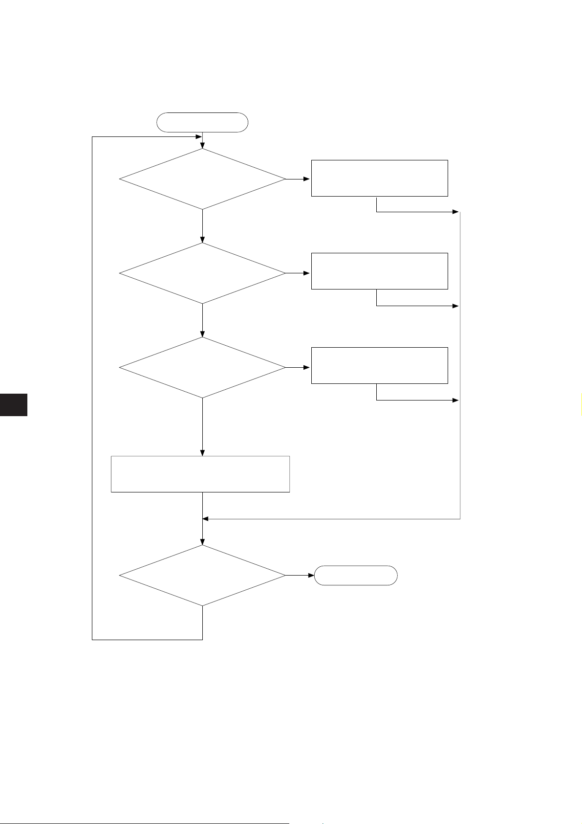
(4) Recovery method at communication errors
① Check flow chart
Occurrence of error
Connection status of
cable/connector are normal.
YES
First communication?
NO
Does the error occur
continuously?
8
YES
NO
YES
NO
See “Check cable/connector”
on next page.
See “During initial communication” on page 8·57.
See “When the communication
error occurs instantaneously ”
on page 8·59.
See “When the communication error
occurs continuously” on page 8·60.
Recovery
NO
YES
Normal operation
8·54
Page 93

② Check cable/connector
Error only 1 station
Monitor “individual communication flag”
in support tool.
Set the error operation mode of a
JW-20CM master module to “2.”
NO
NO
YES
YES
Exchange JW-20CM
At plural station error
Check and exchange the “bus
cable” and “branch cable” to
the station with the error or the
“station error module where
the error occurred.”
FT lamp turns ON
See next page
As errors on the junction from the main cable to the drop cable or the contact failure on the
connecting point of each station or errors of the master module are assumed, check with the
following procedure.
8
8·55
Page 94

• If the bus cable between the slave station 05
03
(8)
02
01
(8)
(8)
04
Master
(8)
station
B
A C
State of an individual communication flag
D
7
6 5
D
0
1234
(8)
and 06
05
(8)
Disconnection
(8)
is disconnected in the following system.
07
06
(8)
(8)
D
OFF
Unstable
Remove the connector on point
A, and turn ON the termination
resistance of the master station.
OFF
As the communication possible stations
(8)
, 02
(8)
, 01
(8)
03
, and 04
(8)
are normal, the
state of communication monitoring flag is
as follows.
D
Connect the A connector, and
then remove the connector on
point B.
7
6 5
OFF OFF
ON
There is no normal station amoung
commiunicatable station 05, 06, 07
(8)
and 05
D
7
OFF
is unstable.
6 5
Unstable
OFF
D
0
1234
(8)
,
D
0
1234
8
Remove the connector on point
C and make sure the B
connector is not connected.
As the communication possible station
(8)
is normal, abnormal points exists
05
ahead of the point C.
D
7
D
06 5
1234
OFF
Connect the C connector and
make sure the B connector is
not connected, and remove the
connector at the next point to
the point D.
The station 05
communication possible stations, but the
station 05
06
states occur between the point C and the
point D.
D
OFF OFF
Disconnection in the bus cable and the
branch cable between the station 05
(8)
, or contact failure of the connectors
06
Error on the slave station 06
(8)
(8)
OFFON
(8)
and 06
(8)
is unstable and the station
(8)
is turned to OFF, so the abnormal
7
(8)
become
D
06 5 1234
Unstable
CountermeasureCause
Remove both the bus cable and
and
the branch cable connectors. After
that, shorten one of these
connectors and check conductivity
using a tester.
Exchange the slave module.
8·56
Page 95

③ During initial communication (start-up of the system)
Check the error code of master station
· When the master station indicates error code BF
(H)
The cause may be a parameter setting error of the master station. Check the master station
parameters.
(See the next page)
·When the master station indicates error code C1 to FF
(H)
The cause may be a error of slave station. Check the error code of slave station.
·When the COMM lamp of master station is OFF (SD, RD, and CD are flickering)
Check the following master station’s parameters
sserddaretemaraP stnetnoC eulavgnitteS
)8(
777300
hctiwstratS10
· Other cases
Check the switches of the communication module
Check optional cable of PC (The PC does not operate normally without an optional cable.)
Check cable and connector
Check error code
Check the error code of slave station
· When the error code of slave station is no display and FAULT lamp is ON
The cause may be error of wiring. Check for wiring.
·When the slave station indicates error code 93
When the slave station indicates error code 9F
(H)
to 95
(H)
(H)
8
· The cause may be a parameter setting error of the slave station.
Check the slave station parameters.
· When relation I/O is error
Check I/O and rack panel.
· Other cases
Check the switches of the communication module
Check optional cable of PC (The PC does not operate normally without an optional cable.)
Check cable and connector
8·57
Page 96

Parameter setting range
<Fixed allocation>
·When fixed allocation is used, set parameter within the range shown below:
コ0000
A
コ1577
1
2
•
•
•
N
B
N
B
N
1 to n : Number of slave stations (1 ≦ n ≦ 32 or 63)
A : Remote I/O top address
N : Number of slave station I/O points (fixed to 64 points or
128 points)
B1 to Bn : Blank between stations
1
2
(Setting of JW model special I/O module)
retsigerataD
seludomforebmuN
snoitatsllafolatotnisetyb215ot0
snoitatsllafolatotniseludom23otpU
noitatsevalsetomerreplatotnisetyb821ot0
noitatsevalsetomerrepseludom8otpU
<Manual allocation>
8
· When the manual allocation is used, set parameter within the range shown below:
コ0000
A
1
A
2
A
n
コ1577
1
2
•
•
•
N
N
N
n
(Setting of JW model special I/O module)
retsigerataD
seludomforebmuN
1 to n : Number of slave stations (1 ≦ n ≦ 63)
A1 to An : Remote I/O top address
N1 to Nn : Number of slave station I/O bytes (0 ≦ Nn ≦ 128)
N1 + N2 + · · · + Nn ≦ 512
noitatsevalsetomerreplatotnisetyb821ot0
snoitatsllafolatotnisetyb215ot0
noitatsevalsetomerrepseludom8otpU
snoitatsllafolatotniseludom23otpU
8·58
Page 97

④ When the communication error occurs instantaneously.
Cause may be:
• Noise on the communication line.
• Fault of a communication module.
• Fault of a communication cable.
Check the error’s timing.
When the error occurs synchronous with a peripheral industrial robot’s operation, noise to the
communication line may be a cause. Consider arrangement of the wiring route.
Identify the error station.
When the error occurs at only the specific station, the cause may be the station or nearby. Check
the following items.
• Setting of the LT (termination resistance) switch.
• Check cables/connectors
Looseness or removal of connectors (turn right until fixed securely)
Whether connectors are assembled to cables appropriate (check insulation/conductivity)
Cable length should be less than 1 km
Branch cable length should be less than 40 cm
• Error code (See page 8·52)
When identification of the cause is difficult.
Condition of the circuit may be unstable. (See page 8·52 “check items of cables and connectors”)
· Looseness or removal of connectors (turn right until fixed securely)
·Whether connectors are assembled to cables appropriate (check insulation/conductivity)
· Cable length should be less than 1 km
· Branch cable length should be less than 40 cm
8
8·59
Page 98

⑤ When the communication error occurs continuously.
Identify the error station.
Specify the error’s station using the communication flag etc., (see page 8·51) and error code (see
page 8·47). Then check this station.
• Check the power of the error’s station.
•Check the error code of the error’s station.
• Check cables/connectors
Looseness or removal of connectors (turn right until fixed securely)
Whether connectors are assembled to cables appropriate (check insulation/conductivity)
Cable length should be less than 1 km
Branch cable length should be less than 40 cm
When identification of the cause is difficult.
Condition of the whole circuit may be unstable.
Check cables and connectors.
· Looseness or removal of connectors (turn right until fixed securely)
·Whether connectors are assembled to cables appropriate (check insulation/conductivity)
· Cable length should be less than 1 km
· Branch cable length should be less than 40 cm
8
8·60
Page 99

Chapter 9 Data Link
9-1 Description for data link function
· The data link function us used to send and receive ON/OFF signals (relay link: max. 2048 points) and
numerical data (register link : max. 2048 bytes) by PCs or between PC and personal computers connected
in the satellite net system.
· The master station and slave stations are connected using a single coaxial cable. As the JW-20CM
network module can control the data communications, the PC does not need any special programming.
·When the JW-20CM is assigned as a slave station, it has the standard function and memory capacity
save function for data link. But the data contents for receiving from other stations is different between
these two functions. (When the JW-20CM is used as a master station, only the standard function is
available.)
[When all of a master station and slave stations are JW-20CM]
• Master station Data link (Standard function) Receiving data are all relay link area, and
• Slave station Data link (Standard function) all register link area of all stations.
Data link
(Memory capacity save function)
}
In order to effectively use the memory,
unify a partial data area or sending/
receiving address (program) of slave
stations.
·A maximum of 6 modules (a mixed installation of master and slave stations is allowed) can be installed
on one PC.
·A maximum of 64 stations can transfer data on one network with maximum cable length of 1 km.
Personal computer
(8)
Master station 00
Network module
(JW-20CM)
PC PC PC
Slave station 01(8)
Network module
(JW-20CM)
(64 stations max., Total extension length: 1km max.)
Slave station 01(8)
Network module
(JW-20CM)
(64 stations max., Total extension length: 1km max.)
slave station 02(8)
Network module
Slave station 02(8)
Network module
JW20
JW20H
JW30H
(JW-22CM)
Slave station 77(8)
Network module
Slave station 76(8)
Network module
(ZW-20CM)
(ZW-20CM)
Slave station 77(8)
Network module
(JW-20CM)
9
·Both JW and ZW model PCs can be connected on the same cable.
9·1
Page 100

9-2 Communication method
[1] Data link (standard function)
Each station sends data in its sending area cyclically and stores data received from other stations in
its receiving area.
Station number 00(8) Station number 01(8) Station number 02(8) Station number 03(8)
:Sending area
:Receiving area
For the JW-20CM to execute automatically these sending and receiving procedures, a special program
for communication is required. Data link have relay link and register link. They can use at the same
time.
noitcnuF stnetnoC
knilyaleRnoitacinummocM:N)setyb652(.xam8402:stniopknilfo.onlatoT
knilretsigeRnoitacinummocM:N.xam8402:setybknilfo.onlatoT
(1) Relay link function
Mainly used for sending and receiving ON/OFF information
[Example] In the case of sending 1-byte data from a master station and slave stations 01 and 02.
Master station (PC00) Slave station (PC01) Slave station (PC02)
コ0200
コ0201
コ0202
PC00 Program PC01 Program PC02 Program
9
02010
02020
02000
02000 02000
02010
02020
02010
02020
:
Send
:
Receive
• The link relay of the receiving station must be programmed as input signal by the PC programming. Also, it may be used as source (S) side of application instruction.
• The sending and receiving data correspond in bits of one point unit.
コ0200
コ0201
7 6 5 4 3 2 1 0
7 6 5 4 3 2 1 0
Is the same value as
コ
0201 of the slave station.
コ0200
コ0201
7 6 5 4 3 2 1 0
コ
Is the same value as
7 6 5 4 3 2 1 0
0200 of the master station.
9·2
 Loading...