

Page 1

SHARF’
SERVICE
MANUAL/SERVICE-ANLElTUNGIMANUEL
DE SERVICE
PHOTO:
JC-S58HlY)
S97E3JC-S58HY
JC-S57
(Y/WBL/W/GY)
JC-S58
(For UK, Canada, Australia)
W/R/BL/W/GY)
In the interests of user-safety the set should be restored to its
original condition and only parts identical to those specified be
used.
Im
lnteresse
der
Benutzer-Sicherheit sollte
dieses
Gerdt
wieder
auf
seinen ursprtinglichen
Zustand
eingestellt und
nur die
vor-
geschriebenen
Teile
verwendet werden.
Dans
I’interbt
de la
securite
de I’utilisateur,
I’appareii
devra
btre
reconstitue
dans sa condition premiere et seules des pieces iden-
tiques a
celles soQcifi6e.s. doivent
6tre utilisees.
1
-i
INDEX TO CONTENTS
0
Page
SPEClFlCATIONS
Page
.................................................
2,3
SCHEMATIC DIAGRAM/WIRING SIDE OF
NAMES OF PARTS
...............................................
2,3
P.W.BOARD
...
..................................................
9-1
1
DISASSEMBLY
.....................................................
4,5
EXPLODED
VIEW..
............................................
12,13
ADJUSTMENT .
....................................................
6-8 PACKING METHOD
(JC-S58
FOR UK ONLY)
............
14
NOTES
ON SCHEMATIC
DIAGRAM..
......................
6-8
REPLACEMENT PARTS
LIST.. ...........
:%.
..............
1 5-l 8
@I
INHALTSVERZEICHNIS
Seite
Seite
TECHNISCHE
DATEN..
..........................................
2,3
SCHEMATISCHER SCHALTPLANI
BEZEICHNUNG
DER
TEILE..
...................................
2,3
VERDRAHTUNGSSEITE
DER
LEITERPLATTE
........
9-11
ZERLEGEN
...........................................................
4,5
EXPLOSIONSDARSTELLUNG..
............................
12,13
EINSTELLUNG..
....................................................
6-8
ERSATZTEILLISTE
............................................
15-l 8
ANMERKUNGEN ZUN SCHEMATISCHEN
SCHALTPLAN
....................................................
6-8
0
TABLE DES MATIkRES
Page
CARACT~RISTIQUES..
Page
..........................................
2,3
DIAGRAMME SCHi?MATIQUE/C6TG CABLAGE
DE
NOMENCLATURE..
...............................................
2.3
LA PLAQUETTE DE MONTAGE
IMPRIME..
...........
9-l 1
DeMONTAGE.. .....................................................
4,5
VUEEN&LATE..
.............................................
RCGLAGE
i 2,i
3
............................................................
6-8
LISTE
DES
PIkES
DE RECHANGE
.....................
15-18
REMARQUES
CONCERNANT LE DIAGRAMME
SCHEMATIQUE.. ................................................
6-8
SHARP CORPORATION
Page 2

GENERAL
Power source:
(JC-S58)
Power source:
(JC-S58H/S57)
Output power:
(JC-S57/S58)
Output power:
(DIN 45 324)
(JC-S58H)
Dimensions:
Weight:
RADIO
Frequency range:
(JC-S571S58)
Frequency range:
(JC-S58H)
FOR A COMPLETE DESCRIPTION OF THE OPERATION OF THIS UNIT, PLEASE
REFER TO THE OPERATION MANUAL.
SPECIFICATIONS
TAPE DECK
DC 3 V (UM/SUM-3,
R6,
HP-7 or
Tape:
“AA” cell x 2 or external DC 3 V)
Compact cassette tape
Frequency response: 40 - 10,000 Hz
DC3 V KJM/SUM-3 or R6 x 2 or
external DC 3
V)
Signal/noise ratio:
54
dB
Max; 60 mW (30 mW + 30
mW)
(DC operation)
RMS;
40 mW (20 mW + 20
mW)
(DC
operation, 10% distortion)
Max; 60 mW (30 mW + 30
mW)
(DC operation)
HEADPHONES
Type:
Impedance:
Over-head
32 ohms
RMS;
40 mW (20 mW + 20
mW)
(DC operation)
Width; 85 mm
(3-3/8”)
Height; 121 mm
(4-25/32”)
Depth; 36.5 mm
(l-7/16”)
280 g (9.9 oz.) without batteries
FM;
87.6 -108 MHz
AM; 526.5
-
1606.5
kHz
FM; 87.5 -108 MHz
AM; 526.5
- 1,606.5
kHz
1.
Headphones Socket
2. Function Selector Switch
3.
Power/Battery Indicator
4. Band Selector Switch
5.
Tuning Control
6. Tape Direction Button
7.
Cassette Compartment
8.
Play Button
9.
Stop Button
10. Fast Forward/Rewind Buttons
11. Reverse Mode Switch
12.
Graphic Equalizer
13.
Battery Compartment
14. External DC Power Input Socket
15.
Volume Control
Specifications for this model are subject to change without prior notice.
NAMES OF PARTS
-2-
Page 3

EINE VOLLSTANDIGE BESCHREIBUNG
DER
BEDIENUNG
DIESES GERATES IST
IN DER
BEDIENUNGSANLEITUNG
ENTHALTEN.
TECHNISCHE DATEN
POUR LA DESCRIPTION COMPLETE DU
FONCTIONNE-
MENT DE CET APPAREIL, SE REPORTER AU MODE
D’EMPLOI.
CARACTiRlSTlQUES
GENERAL
Alimentation:
(JC-S58)
Alimentation:
(JC-S58H)
Puissance de sortie:
(JC-S58)
3 V CC (UM/SUM-3, R6, HP-7 ou
“AA” x 2 ou 3 V CC externe)
3 V CC (Pile UM/SUM-3 ou R6 x
2 ou 3 V CC externe)
Max; 60 mW (30 mW + 30
mW)
ALLGEMEIN
Spannungsversorgung:
Ausgangsleistung:
(DIN 45 324)
Abmessungen:
Gewicht:
RADIOTElL
Frequenzbereich:
CASSETTENDECK
Band:
Frequenzgang:
Rauschabstand:
KOPFHdRER
TYP:
Impedanz:
3 V Gleichspannung (UM/SUM-3
oder R6 x 2 bzw. 3 V externe
Gleichspannung)
Max; 60 mW (30 mW + 30
mW,
Gleichspannungsbetrieb)
Sinusleistung; 40 mW (20
mW
+ 20
mW,
Gleichspannungs-
betrieb)
Breite; 85 mm
Hohe;
121 mm
Tiefe;
36,5
mm
280 g
fohne
Batterien)
UKW;
87,5 -
108 MHz
MW;
526,5 - 1606,5 kHz
Kompaktcasettenband
40 - 10000 Hz
54
dB
Kopfbtigel
32 Ohm
Puissance de sortie:
(DIN 45 324)
(JC-S58H)
Dimensions:
Poids:
RADIO
Gamme de frequence:
(JC-S58)
Gamme de frequence:
(JC-S58H)
CASSETTE
Bande:
Reponse
en frequence:
Rapport signal/bruit:
CASQUE
Type:
Impedance:
(Fonctionnement sur CC)
RMS; 40 mW (20 mW + 20
mW)
(Fonctionnement sur CC, 10% de
distorsion)
Max; 60 mW (30 mW + 30
mW)
(Fonctionnement sur CC)
RMS; 40 mW (20 mW + 20
mW)
(Fonctionnement sur CC)
Largeur; 85 mm
Hauteur; 121 mm
Profondeur;
36,5
mm
280 g sans piles
FM;
87,6 -
108
MHz
PO;
526,5
- 1.606,5
kHz
FM;
87,5 -
108
MHz
PO;
526,5
- 1.606,5
kHz
Cassette compacte
40 -
10.000
Hz
54
dB
Dessus de
t&e
32 ohms
Die technischen Daten
fur
dieses
Model1
kijnnen ohne vor-
herige
Ankiindigung
Anderungen unterworfen sein.
BEZEICHNUNG DER TEILE
1.
Kopfhorerbuchse
2.
Funktionswahlschalter
3.
Betrieb/Batterie-Anzeige
4.
Wellenband-Wahlschalter
5.
Abstimmsteller
6.
Bandrichtungswahlschalter
7.
Cassettenfach
8.
Wiedergabetaste
9.
Stopptaste
10.
Schnellvorlauf/Rijckspul-Tasten
Il. Rijcklauf-Betriebsartenschalter
12.
Frequenzgangentzerrer
13.
Batteriefach
14.
AuBengleichspannungs-Eingangsbuchse
15.
Lautstarkesteller
Les caracteristiques de ce modele sont sujettes a modification sans preavis.
NOMENCLATURE
I.
Prise de
casque
2. Selecteur de
fonction
3. Temoin
d’alimentation/piles
4. Selecteur de gamme d’ondes
5. Commande d’accord
6.
Touche
de sens de defilement
7. Compartiment de cassette
8.
Touche
de lecture
9.
Touche d’arrdt
10. Touches d’avance rapidelrebobinage
11. Commutateur de mode d’inversion
12.
Egaliseur
graphique
13. Logement de piles
14. Prise d’entree d’alimentation CC exterieure
15. Commande de volume
-3-
Page 4

0
DISASSEMBLY
Caution on Disassembly
Follow the below-mentioned notes when disassembling the
unit and reassembling it, to keep its safety and excellent
performance:
1. Take cassette tape out of the unit.
2. Be sure to remove the batteries from the unit.
3. After servicing the unit, be sure to rearrange the leads
where they were before disassembling.
4. Take sufficient care on static electricity of integrated circuits and other circuits when servicing.
STEP REMOVAL
PROCEDURE
FIGURE
1
Rear Cabinet1. Open the battery
4-l
compartment lid . . . . . . . . .
(A)xl
2.
Screw
. . . . . . . . . . . . . . . . . . . . . . .
(6)x4
Cassette
Holder
1.
Screw . . . . . . . . . . . . . . . . . . . . . . .
(C)xl
3
I I
Mechanism1. Knob
.........................
(D)xl
4-2
Block
2.
Screw..
......................
(E)x4
I
I
(B)
x2
02
x5mm
Rear Cabinet
,1..
(Blx2
Q2 xemm
(A) xl
(C)xl
Battery Comportment Lid
01.
7x5mm
Holder
Figure
4-l
(El
x4
01.4
r3mm
Figure 4-2
Block
Moln PWB
Figure 4-3
-4-
Page 5

03
ZERLEGEN
DEMONTAGE
Vorsichtsmassregeln
Fiir
Das Zerlegen
Beim Zerlegen und Zusammenbauen des
Gerdtes
die
folgen-
den Anweisungen befolgen,
urn
dessen Betriebssicherheit
und ausgezeichnete Leistung aufrechtzuerhalten.
1.
Die Cassette
aus
dem
Gerat
entfernen.
2. Unbedingt die Batterien
aus
dem
Gerat
entfernen.
3.
Nach Warten
des
Gerates
darauf achten, die Leitungen
wieder so zu verlegen, wie sie vor den Zerlegen
ange-
ordnet
waren.
4. Beim
Ausftihren
von Wartungsarbeiten auf statische
Elektrizitat
.der integrierten Schaltkreise und anderen
Schaltungen achten.
/ 1
FT;
ENTFERNEN
VERFAHREN
ABBIL-
/
I
DUNG
Casset-
tenfach
1. Schraube
..,................ (Clxl
1.
Knopf .......................
(Dtxl
2. Schraube ................... (E)xl
4
Hauptleiter-1. Schraube ................... (Flx2 4-3
Platte
2. WBscher..
..................
(GIxl
3.
Haken
.......................
(Hlxl
prkautions pour le
d6montage
Lors du
demontage
de
I’appareil
et de son remontage,
sui-
vre
les
precautions ci-dessous, pour maintenir la
sacurite
et d’excellentes performances.
1. Deposer la bande cassette de
I’appareil.
2. S’assurer de retirer les piles de
I’appareil.
3.
Apres
la reparation de I’appareil, s’assurer de redisposer
les fils tel
qu’ils
Btaient
avant le
d&montage.
4. Faire attention a
I’electricite
statique des circuits
integres
et des autres circuits
lors
de la
reparation.
1
I~TAPEI
DEPOSE
/
PROCEDE
/
FIGURE
/
1
Coffret
1.
Ouvrir le abattant
1
4-l
arriere
du
compartiment
des
piles . . . . . . . . . . . . . . . . . . . . . . . . . . . . .
(A)
2. Vis
. . . . . . . . . . . . . . . . . . . ..*......
(BIx4
2
1.
Vis
. . . . . . . . . . . . . . . . . . . . . . . . . . .
(C)xl
4-l
I
I
-5-
Page 6

ADJUSTMENT
As for adjusting method refer to the relevant explanation
TUNER SECTION
in Service Manual “ADJUSTMENT PROCEDURES OF AUDIO PRODUCTS”.
fL:
Low-range frequency
fH:
High range frequency
. FM IF/RF
MECHANISM
SECTION
. Driving Force check
Torque Meter
Play: TW-2412
Reverse olav: TW-2422
Specified value
Over 50
g
Over 50
q
. Torque Check
Torque Meter
Play: TW-2111
Specified value
26 to 45 g.cm
Reverse play: TW-2121
Fast forward: TW-2231
=
Head Azimuth
Test Tape
MTT-114
1
26 to 45 g.cm
Over 60 g.cm
Instrument Connection
Headphones socket
. Tape Speed
Test Tape Adjusting Specified
instrument
Point value
Connection
MTT-111
VR3 3,000 + 90 Hz Headphones
socket
Test Stage
IF
Detection
Frequency
cover
Tracking
Specified value/
Adjusting Point
Tl
T3
87.1 MHz fL:
L2
(JC-S57/S58)
87.3 MHz fL:
L2
(JCS58H)
108.8 MHz fH: TC2
(JC-S57/S58)
108.3 MHz fH: TC2
IJCS58H)
88.0 MHz: Ll
108.0 MHz:
TCl
Instrument
Connection
Input: TP3
Output: TP4
Input:
TPl
Output: Headphones
Socket (load
resis-
tance:
32 ohms)
. VCO Frequency
Frequency 1 Dial
setting
88
MHz
at
88
MHz
60
dB
Adjusting
Point
zSr;fied 1
Instrument
Connection
VRI
19
kHz TP6
2
50 Hz
. AM IF/RF
Test Stage
IF
Frequency
cover
Tracking
Specified value/
Adjusting Point
460
kHz: T2
fL:
L4
fH: TC4
600
kHz: L3
1,400
kHz:
TC3
Instrument
Connection
Input: Antenna
Output: TP5
Input: Antenna
Output: Headphones
socket
(load resis-
tance: 32 ohms)
MAIN
PWB-AI
Figure 6 ADJUSTMENT POINTS
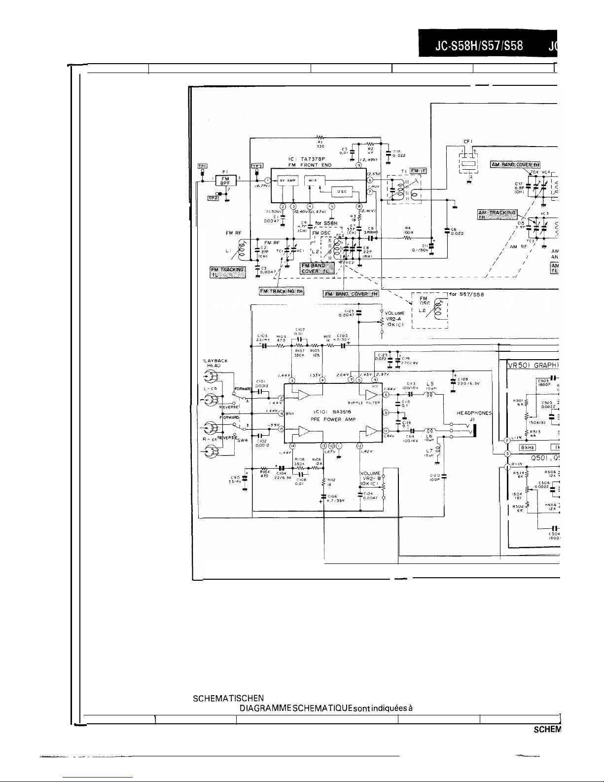
NOTES ON SCHEMATIC DIAGRAM
. Resistor:
TO differentiate the units of resistors, such symbol as K is
used: the symbol K means 1000 ohm and the resistor
with-
out any symbol is ohm-type resistor.
. Capacitor:
To indicate the unit of capacitor, a symbol P is used: this
symbol P means micro-micro-farad and the unit of the
ca-
pacitor without such a symbol is microfarad. As to
electro-
lytic
capacitor, the expression “capacitance/withstand
voltage” is used.
(CH), (TH), (RH), (UJ):
Temperature compensation
(ML): Mylar type
.
The indicated voltage in each section is the one measured
by Digital Multimeter between such a section and the
chas-
sis with no signal given.
1. Tuner
(
1:
FM mode
Marking except for
(
1:
AM mode
.
Schematic diagram and Wiring Side of
P.W.Board
for this
model are subject to change for improvement without prior
notice.
(P.P.): Polypropylene type
-6-
Page 7

EINSTELLUNG
Einzelheiten
tiber
das
Einsteilverfahren
sind in den
entsprel-
chenden
Erklarungen
der Service-Anleitung
“EINSTELLVER-
FAHREN FUR
AUDIOPRODUKTE”
angegeben.
TUNER-TEIL
fL:
Niedriger Frequenzbereich
fH: Hoher
Frequenzbereich
MECHANISMUS-TEIL
.
uberprtifung
der Antriebskraft
Drehmomentmesser
Vorgeschriebener Wert
Wiedersabe: TW-2412
/
Dber
500
Rucklauf-Wiedergabe:
TW-2422
Dber 50
g
.
Uberprtifung
des Drehmoments
/
Drehmomentmesser
/
Voraeschriebener Wert
Wiedergabe: TW-2111
Rticklauf-Wiedergabe:
TW-2121
Schnellvorlauf: TW-2231
. Kopfazimut
/
Testband
MTT-114
26 45 g.cm
26 - 45 g.cm
Uber 60 g.cm
InstrumentenanschluR
Kopfhorerbuchse
. Bandgesohwindigkeit
1
Testband
1
Einstellounkt 1 Voraeschriebe- 1 Instrumente-
1
MTT-111 VR3
ner Wart
3 000
2
90 Hz
nanschlul3
Kopfhcrer-
buchse
.
UKW-Zwischen-IHochfrequenz
Priifstufe
Vorgeschriebener
WertiEinstellpunkt
ZF
Tl
Demodulation
T3
Instrumentenanschlul3
Eingang: TP3
Ausgang: TP4
Frequenzbereich
Abtastuna
87,3
MHz
fL:
L2
Eingang: TPI
108,3
MHz fH: TC2 Ausgang: KopfhB-
88.0 MHz:
Ll
rerbuchse
(Bela-
rtand:
”
I ~’
108,O
MHz: TC
1
( s$mgsz(der:
,
. Frequenz des spannungsgesteuerten
Oszillators
.
MW-Zwischen-IHochfrequenz
Prtifstufe
ZF
Freauenz-
Vorgeschriebener
WertiEinstelipunkt
460
kHz:
T2
fL:
L4
Instrumentenan-
schlul3
Eingang: Antenne
Ausgang: TP5
Eingano: Antenne
1
DIE
ANWEISUNG
DER
FREQUENZEINSTELLUNG -
der Postverfiigung Nr.
478/l
981 zu entsprechen, wird
der UKW-Frequenzbereich mit
Hilfe
der Oszillatorspule
(LZ-untere
Eckfrequenz:
B7,5 MHz)
und des
Oszillatortrim-
mers
(TC2-obere
Eckfrequenz:
108,O
MHz) eingestellt.
ANMERKUNGEN ZUM SCHEMATISCHEN SCHALTPLAN
.
Widerstande:
Urn die Einheiten der
Widerstande
unter-scheiden zu
kdn-
nen, werden Symbole wie K benutzt. Das Symbol K
bedeu-
tet
1000
Ohm Bei
Widerstanden
ohne Symbol handelt es
sich
urn ohmsche
Widerstande.
. Kondensatoren:
Zum
Bezeichnen der Kondensatoreinheit wird das Symbol
P
benutzt; dieses Symbol P bedeutet Nanofard. Die Einheit
eines Kondensators ohne Symbol ist Mikrofarad.
Fijr Elek-
trolytkondensatoren wird die Be-zeichnung
“Kapazitat/
Stehspannung” benutzt.
(CH), (TH), (RH),
(UJ):
Temperaturkompensation
(ML): Mylarkondensator
(P.P):
Polypropylentyp
Die in den einzelnen Teilen angegebenen Spannungen
wer-
den mit einem
Digitalvielfachmel3gerat
zwischen dem
be-
treffen den Teil und dem Chassis ohne
Signalzuleitung
gemessen.
1. Tuner
( 1:
UKW-Betriebsart
Kennzeichnung
aul3er ( 1:
MW-Betriebsart
Anderungen
des schematischen Schaltplans
und
der
Ver-
drahtungsseite der Leiterplatte
fijr
dieses Model1 im Sinne
von Verbesserungen jederzeit vorbehalten.
-7-
__--l-l__-..---l
--
--^--.-+.-+
Page 8

RtGLAGE
PARTIE TUNER
Pour la
methode
de
reglage,
se reporter aux indications
con-
cernees
dans le Manuel de service “PROCEDES DE
REGLAGE DES PRODUITS
ACOUSTIQUES”.
fL:
basse
frequence
fH:
haute
frequence
PARTIE MECANISME
.
Vbrification
de la force
d’entrainement
.
FI/RF
FM
/
Torsiometre
I Valeur
so&zifif?!e
Etage d’essai
Valeur specifiee/Point
de reglage
Tl
T3
87,l
MHz
fL:
L2
(JCS58)
87.3 MHz
fL:
L2
(JC-S58H)
108,8
MHz
fH:
TC2
(JC-S58)
108,3
MHz
fH:
TC2
(JC-S58Hl
88,0
MHz:
Ll
108,O
MHz: TC 1
Instrument de con-
nexion
Entree: TP3
Sortie: TP4
Entree: TPI
Sortie: Prise de
casque (Resistance
de charge: 32
ohms)
Lecture: TW-2412
Plus de 50
g
Lecture d’inversion:
TN-2422
Plus de 50
g
FI
Detection
Couverture de
freauence
.
Vbrification
du couple
Torsiometre
Valeur specifiee
Lecture: TW-2111
26 B 45 g.cm
Lecture d’inversion: TW-2121
26 ?I 45 g.cm
Avance raoide: TW-2231
Plus de 60
a.cm
Alignement
. Azimut de la
t&e
Bande d’essai
/
instrument de connexion
.
Frbquence
VCO
1
MTT-114
/
Prise de casaue
Point de
reglage
Valeur
Instrument
sp&ifiee
de con-
nexion
19
kHz
TP6
+ 50 Hz
. Vitesse de defilement
Bande d’essai / Point de I Valeur
/
Instrument de
1
VRI
MTT-111
reglage
VR3
specifiee
3.000 +
90 Hz
connexion
Prise de
casque
60
dB
* FURF
AM (PO)
Etage d’essai
FI
Couverture de
frequence
Alignement
Valeur specifiee/Point Instrument de conde reglage
nexion
460 kHz: T2
Entree: Antenne
Sortie:TPS
fL: L4
Entree: Antenne
fH: TC4
Sortie: Prise de
600
kHz:
L3
casque (Resistance
1.400 kHz:
TC3
de charge: 32
ohms)
REMARQUES CONCERNANT LE DIAGRAMME SCHeMATIQUE
Resistance:
Pour
differencier
les
unites
de resistances, on utilise des
symbole
tels
que K: le symbole K signifie 1000 ohms et la
resistance
donnee
sans symbole est une resistance de type
ohm.
Condensateur:
Pour indiquer
I’unite
de condensateur, on utilise le symbole
P;
ce symbole P signifie micro-microfarad, et
I’unite
de
con-
densateur
donnee
sans ce symbole est
le microfarad. En ce qui
concerne
le condensateur
Blectroly-
tique, on utilise I’expression “tension de
regime/capacite”
(CH), (TH), (RH),
(UJ):
Compensation de temperature
(ML): Condensateur Mylar
(P.P): Type Polypropylene
.
La tension
indiquee
dans chaque section est
celle mesuree
par un
multimetre numerique
entre la section en question
et le
chassis,
en I’absence de tout signal.
1. Tuner
( 1:
Mode FM
Marque
except6 ( ):
Mode AM (PO)
Le diagramme
schematque
et le
tote cablage
de la
PMI
de
ce
modele
sont sujets a modifications sans
preavis
pour
I’amelioration
de ce produit.
-8-
Page 9
I -
c
1
2
I
3
4
5
6
r
r
VR501 GRAPHI
-
. NOTES ON SCHEMATIC DIAGRAM can be found on page 6.
ANMERKUNGEN ZUM
SCHEMATISCHEN
SCHALTPLAN stehen auf Seite 7.
. REMARQUES CONCERNANT LE
DIAGRAMME SCHEMATIQUE sent indiquees 2
la page 8.
1
I
2
3
I
4
5
-9-
6 I
Figure9SCHEM
-_
. -. . ..----_-c-
--
Page 10

I
7
8
3
I
10
1
11
I
12
)I
GRAPHIC
EQUALIZER
0501
-
AN7025
G
DESCRIPTION
SW1
BAND SELECTOR
SW2
FUNCTION SELECTOR
SW3
MAIN
SW4
FORWARD/REVERSE
I
POSITION
I
FM ST - FM - AM
RADIO - TAPE
ON - OFF
H
1
FORWARD REVERSE
Mix FM”:: ;;; 1Y IlM AM
IN
IF I\cIc BET
IN
7
8
9
I
10
11
12
,
SCHEMATIC DIAGRAM
Page 11

-EL-
M~IA
a3ao7dx3 uruaw3 EL ernfi!d
cl
I
c
I
h
I
P
I
T
1
-soI
I
1 IV-UMdl
01
zx 209
9
9
v
&
Z
1
Page 12

1
2
I
3
4
I
5
I
6
A
B
C
D
-507x2
-37
E
&.6i72g i,
505x2
F
G
[TOP
VIEW1
[BOTTOM
VIEW]
H
1
I
2
3
4
I
5
6
VIEW
Figure 12 TAPE MECHANISM
-12-
EXPLODED
Page 13

A
0
C
D
E
F
G
~
H
1
I
2
I
R
I
n
I
E
I
.-
!a
1
\
\
\
4
A
\
z-:x
r-3
B
-0
C
1
2
I
3
4
5
I
6
Figure 11 WIRING SIDE OF
P.W.BOARD
-ll-
Page 14

SETTING POSITIONS OF SWITCHES AND KNOBS
Function Selector
/
TAPE/RADIO OFF
/
Band Selector
I
FM-ST
I
Mechanism
, Reverse Mode
OFF
3
Graphic Equalizer
CENTER
1. Polyethylene Bag, Unit
2. Polyethylene Bag, Operation
Manual
3. Polyethylen Bag, Headphones
4. Belt Clip
5. Warranty Card
6. Headphones
(Y)
Headphones
(RI
Headphones
(BL)
Headphones
(W)
Headphones
(GY)
7. Operation Manual
8. Packing Add.
9. Packing Case
(Y)
Packing Case
(R)
Packing Case
(BL)
Packing Case
(W)
Packing case
(GY)
10. Protection Sheet
11. Hand Strap
92LBAG525A
92LBAG 525A
92LBAG 525C
92LCLiP617A
92LG-CARD029B
92LHDPHoNE620B
92LHDPHoNE617B
92LHDPHoNE619B
92LHDPHoNE621 B
92LHDPHoNE940B
92LiNST1039A
92LP-AD
1034A
92LP-CASE1044A
92LP-CASE1045A
92LP-CASE
1046A
92LP-CASE
1047A
92LPCASE 1048A
92LC-PAD
1034A
92LSTRAP
1005A
I I
Figure 14
Page 15

REF.NO.
1101-2
104
104
104
104
104
105
106
107
108
109
110
111
111
111
111
111
___
Ill-1
111-1
111-l
111-l
111-l
Ill-2
111-3
.
111-4
113
114
115
116
PART NO.
DESCRIPTION
CODE
92LGRiP1034B
Rubber,Back
Grip AM
92LCAB1034A-YW
Front Cabinet,(Y)
AK
92LCAB1035A-RD
Front Cabinet,(R)
AK
92LCAB1036A-BL
Front Cabinet,(BL)
AK
92LCAB1037A-WH
Front Cabinet,(W)
AK
92LCAB1038A-GY
Front
Cabinet,(GY)
AK
92LBTML1034A
Battery Terminal AB
92LFSPR943A
Spring,Cassette Push
AC
92LBSPR1034A
Spring,Battery
AC
92LCoV525A
Cover,Band Selector AA
Switch
92LCoV1034A
Cover,Graphic
Equalizer A
E
92LCoV943B
Cover,Function Selector
A A
Switch
9 2 LMECl 0 34CTS 1Cassette Holder Ass’y,(Y)
AT
9 2 LMECl 0 3
5CTSl Cassette Holder Ass’y,(R)
AT
92LMEC103
6CTSl
Cassette Holder Ass’y,(BL) AT
9 2 LMECI 0 3 7CTS 1Cassette Holder
Ass’y,(W)
AT
9 2 LMEC103 8CTS 1Cassette Holder
Ass’y,(GY)
AT
Holder,Cassette,(Y)
-
116
116
116
116
116
116
116
116
116
116
116
116
116
116
116
116
116
116
116
92LPANEL1034A
92LGRiP1034A
92LCT-CoV1034A
92LFSPR943B
92LKNoB943B
92LKNoB943C
92LSPEC1034A
92LSPEC1035A
92LSPEC1036A
92LSPEC1037A
92LSPEC1038A
92LSPEC1039A
92LSPEC1040A
92LSPEC1041A
92LSPEC1042A
92LSPEC1043A
92LSPEC1054A
92LSPEC1055A
92LSPEC1056A
92LSPEC1057A
92LSPEC1058A
92LSPEC1059A
92LSPEC1060A
92LSPEC1061A
92LSPEC1062A
92LSPEC1063A
Holder,Cassette,(R)
-
Holder,Cassette,(BL)
-
Holder,Cassette,(W)
-
Holder,Cassette,(GY)
-
Dial Panel AF
Rubber,Front
Grip AM
Cover,Cassette Holder A
F
Spring,Cassette Up AB
ButtonTape
Direction AB
Knob,Reverse
Mode AF
Label,Specifications,JC-S58 A
B
(Y) for Australia/UK
Label,Specifications,JC-S58 A
B
(R) for Austraka/UK
Label,Specifications,JC-S58 A
B
(BL) for Australia/UK
Label,Specifications,JC-S58 A
B
(W) for Australia/UK
Label,Specifications,JC-S58 A
B
(GY) for Australia/UK
Label,Specifications,JC-S58 A
B
(Y) for Canada
Label,Specifications,JC-S58 A
B
(R) for Canada
Label,Specifications,JC-S58 A
B
(BL) for Canada
Label,Specifications,JC-S58 A
B
(W) for Canada
Label,Specifications,JC-S58 A
B
(GY) for Canada
Label,Specifications,JC-S58 A
B
H(Y)
Label,Specifications,JC-S58 A
B
H(R)
Label,Specifications,JC-S58 A
B
H(BL)
Label,Specifications,JC-S58 A
B
H(W)
Label,Specifications,JC-S58 A
B
WV
Label,Specifications,JC-S57 A
B
V)
Label,Specifications,JC-S57 A
B
CR)
Label,Specificattons,JC-S57 A
B
(BL)
Label,Specrfications,JC-S57 A
B
W)
Label,Specifications,JC-S57 A
B
(W
REF.NO.
PART NO.
DESCRIPTION CODE
118
119
120
121
122
123
124
125
126
127
92LHoLD943A
Holder,LED
92LKNoB943A
Knob,Tuning
92LPiNT-943A
Dial Pointer
92LS-CHS943A
Frame
92LS-CHS943B
Frame
JKNBP0316AFSA
ButtonPlay
JKNBP0317AFSA
ButtonStop
JKNBP0318AFSA
ButtonFast
Forward
92LM-SHLD943A
Shield Plate
92LLiD1034A-YW
Lid,Battery Compartment,
m
92LL
iD1035A-RD
Lid,Battery Compartment,
(RI
92LL
iD1036A-BL
Lid,Battery Compartment,
W-1
92LLiD1037A-WH
Lid,Battery Compartment,
w
92LL i
D1038A-GY
Lid,Battery Compartment,
VW
92LCoV1034B-YW
Cover,Strap,(Y)
92LCoV1035B-RD
Cover,Strap,(R)
92LCoV1036B-BL
Cover,Strap,(BL)
92LCoV1037B-WH
Cover,Strap,(W)
92LCoV1038B-GY
Cover,Strap,(GY)
92LSHAFT1034A
Shaft,Strap
92LCoV1034C-YW
Cover,Strap,(Y)
92LCoV1035C-RD
Cover,Strap,(R)
92LCoV1036C-BL
Cover,Strap,(BL)
92LCoV1037C-WH
Cover,Strap,(W)
92LCoV1038C-GY
Cover,Strap,(GY)
92L2BTSf8BB
Screw,
d 2 X 8mm
92LSlR4S943C
Screw, 4 1.4 X
3mm
92LSlR4S943D
Screw, 4 1.4 X
4mm
92LSlR7BTS943A Screw,$1.7X5mm
92LSlR7BTS943B Screw,d1.7X3.5mm
92LlR4SPW
Spring
Washer,$1.4mm
92L2BTS+5BB
Screw, d 2 X
5mm
92LlR7Sf3PB
Screw,41.7X 3mm
92LlR8SPW
Spring
Washer,+1.8mm
92LS2S1034A
Screw, 4 2 X
3mm
ACCESSORIES/PACKING PARTS
AA
AB
AC
AD
AC
AB
AB
AB
AB
AB
127
AB
127
AB
127
AB
127
AB
128
128
128
128
128
129
130
130
130
130
130
601
602
603
604
605
606
607
608
609
610
AA
AA
AA
AA
AA
AC
AA
AA
AA
AA
AA
AA
AA
AA
AB
AA
AA
AA
AA
AA
AA
92LBAG525A
Polyethylene Bag,Unit,
Operation Manual
92LBAG525C
Polyethylene Bag,
Headphones
92LC-PAD1034A
Protection Sheet
92LCLiP617A
Belt Clip
92LG-CARD029B
Warranty
Card,JC-S58
for
UK
92LG-CARD131C
Warranty
Card,JC-S58H
92LG-CARD541A
Warranty
Card,JC-S58
for
Canada
92LG-CARD632A
Warranty
Card,JC-S58
for
Australia
92LiNST1039A
Operation
Manual,JC-S58
AA
AA
AB
AC
AC
AC
AC
AC
AC
92LiNST1054A
92LiNST1059A
92LP-AD1034A
92LP-CASE1039A
92LP-CASE1040A
92LP-CASE1041A
92LP-CASE1042A
92LP-CASE1043A
Operation
Manual,JC-S58H
AB
Operation
Manual,JC-S57
AD
Packing Add.
AD
Packing
Case,JC-S58(Y)A G
for Canada
Packing
Case,JC-S58(R)A G
for Canada
Packing
Case,JC-S58(BL)
A
G
for Canada
Packing
Case,JC-S58(W)
A
G
for Canada
Packing
Case,JC-S58(GY)
A
G
for Canada
-17-
Page 16

REF.NO.
PART NO.
DESCRIPTION
CODE
C32
VCKYMFlHBPZlK
220
pF,5OV
AA
c33
VCTYMFlCY223N
0.022 flF,16V
AA
C36,37
VCTYMFlNY333N
0.033 /IF, 12V
AA
c101,102
VCTYBTlCXlPPM
0.0012
pF,16V
AA
C107,108
VCTYMFlEX103K
0.01
/.tF,25V
AA
C115,116
92LCKS50FRlZ
0.1
pF,5OV
AA
Cl20
VCCSMFlHLlOlJ
100
pF,5OV
AA
C123,124
VCTYMFlHV472K
0.0047 p F, 50V
AA
Cl25
VCTYMFlCY223N
0.022 gF,16V
AA
C203
VCKYMFlHBlOZK
0.001 pF,50V
AA
C205
VCTYMFlCY223N
0.022
gF,l6V AA
RESISTORS
(Unless otherwlse
specified.
resistors are
+5%,carbon
type.) (Tubular type
carbon
film reslstor
*5% IS
Identified the symbol MF of the part NO.
VRD-
MFOOOOOOO;
this MF does not mean lead wire.)
Rl
R2
R3
R4
R5
R6
R7
R9
RlO
R11,12
R13
R103,104
R105,106
R107,108
Rlll,llZ
R201
R202
R203
R204
R205
R206
R207
R208
VRD-MFZEEOOOC
0
ohm,l/4W
AA
VRD-MFZEE331J
330 ohms,
1/4W
AA
VRD-MF2EE470J
47
ohms,1/4W
AA
VRD-MFPEE18OJ
18
ohms,l/4W
AA
VRD-MFPEE104J
100
kohm,l/4W
AA
VRD-MFZEE562J
5.6 kohms,l/4W
AA
VRD-MF2EElOZJ
1
kohm,l/4W
AA
VRD-MFZEE183J
18
kohms,1/4W
AA
VRD-MFZEE392J 3.9 kohms,l/4W
AA
VRD-MFPEE104J
100
kohm,l/4W
AA
VRD-MFZEE182J
1.8
kohms,1/4W
AA
VRD-ST2CDlSlJ
150
ohms,l/6W
AA
VRD-MFZEE471J
470 ohms,
1/4W
AA
VRD-MF2EE123J
12 kohms,l/4W
AA
VRD-MF2EE334J
330 kohms,l/4W
AA
VRD-MF2EElOPJ
1
kohm,l/4W
AA
VRD-MFZEE103J
10
kohm,l/4W
AA
VRD-MFZEE681J
680
ohms,l/4W
AA
VRD-MFZEEZR2J
2.2 ohms,1/4W
AA
VRD-STPCDORSJ
0.5
ohms,l/6W
AA
VRD-MFZEE821J
820
ohms,l/4W
AA
VRD-MFZEE221J
220 ohms,1/4W
AA
VRD-STZCD270J
27
ohms,1/6W
AA
VRD-STZCD33
1 J330 ohms,
1/6W
AA
OTHER CIRCUITRY PARTS
Jl
J2
AD
AE
Ml
SW1
AV
AF
SW2
SW3
SW4
92LJACK-5258
Jack,Headphones
92LJACK-525A
Jack,External DC Power
Input
92LM-MoToR943A
Motor with Pulley
92LSWiCH-525B
Switch,Slide Type,Band
Selector
92LSWiCH-525A
Switch,Slide Type,Function
Selector
92LSWiCH-943A
Switch,Leaf Type,Main
92LSWiCH-943B
Switch,Slide Type,
Forward/Reverse
Selector
AF
AD
AG
MECHANICAL
PAliTS
CABINET PARTS
1
LANGGO172AFZZ
Guide,Button
AC
2
LANGG0173AFZZ
Guide
Base,Tape
AB
3
LCHSM0669AFZZ
Main Chassis
-
4
LSLVM0257AFFW
Shaft,Gear
AB
5
LSLVM0258AFFW
Sleeve,F/R Plate
AB
6
LSLVM0259AFFW
Sleeve,Center Gear
AD
7
LSLVM0260AFFW
Sleeve,Head
AC
8
MLEVFZOBlAFZZ
Arm,Head Plate
AE
9
MLEVF2082AFZZ
Plate,ldler
AF
10
MLEVF2083AFZZ
Plate,RVS
AK
REF.NO.
PART NO. DESCRIPTION
CODE
11
MLEVF2084AFZZ
12
MLEVF2085AFZZ
13
MLEVF2086AFZZ
14
MLEVF2087AFZZ
15
MLEVF2088AFZZ
16
MLEVF2089AFZZ
17
MLEVF2090AFZZ
18
MLEVF2091AFZZ
19
MLEVF2092AFZZ
20
MLEVF2093AFZZ
21
MLEVF2094AFZZ
22
MLEVP0774AFZZ
23
MLEVP0775AFZZ
24
MSPRC0697AFFJ
25
MSPRC0698AFFJ
26
MSPRC0699AFFJ
27
MSPRC0700AFFJ
28
MSPRC0701AFFJ
29
MSPR00897AFFJ
T
Plate Ass’y
AE
Lever,Direction
AC
Plate,Lock AE
Lever,Play
AC
Lever,Stop AC
Lever,Fast Forward
AB
Lever,Rewind
AB
Plate,Fast Forward
AD
Plate,Rewind
AC
Gear Plate Ass’y
AE
Plate,Selector
AC
Arm,Cam
Lock
AF
ArmSwing
AB
Spring,Azimuth
AC
Spring,Fast Forward Plate A
B
30
MSPRD0898AFFJ
Spring,Gear Plate
Spring,Back Tension
Spring,Back Tension
Spring,Forward Pinch
Roller
Spring,Reverse Pinch
Roller
Spring,Cam Lock Arm
Spring,Operation
Spring,Lock Plate
Spring,Direction
Spring,Head Plate Arm
Main Belt
Metal,Capstan
ReeLTake-up
ReeLSupply
Flywheel
Flywheel
Gear
Gear
Cam, RVS
Gear,Center
End Cam Ass’y
Pulley,Center
Pinch Roller,Forward
Pinch Roller,Reverse
Head,Playback
Roller,RVS,Left
Roller,RVS,Right
AB
AB
AB
A5
AB
31
MSPRD0899AFFJ
32
MSPRD0900AFFJ
33
MSPRT1326AFFJ
34
MSPRT1327AFFJ
35
MSPRT1328AFFJ
36
92LM-DBELT943A
37
NBRGC0139AFZZ
38
NDAiR0223AFZZ
39
NDAiR0224AFZZ
40
NFLYC0154AFZZ
41
NFLYC0155AFZZ
42
NGERHO251AFZZ
43
NGERH0252AFZZ
44
NGERH0253AFZZ
45
NGERH0254AFZZ
46
NGERH0255AFZZ
47
NPLYR0139AFZZ
48
NRoLY0091AFZZ
49
NRoLY0092AFZZ
50
92LM-P-HD943A
51
NRoLMOlZlAFZZ
52
NRoLM0122AFZZ
501
LX-WZ1064AFZZ
502
LX-WZllO4AFZZ
503
LX-WZ9064AFZZ
504
XAPSF14POZOOO
505
XAPSN17P01800
506
XASSF14P02000
507
XASSN14P01800
508
XASSN14P02500
509
XSPSF14PO4500
511
XSPSN17P09300
512
XSPSN17PlOOOO
513
LX-WZ9073AFZZ
514
LX-WZ9132AFZZ
AB
AB
AB
AB
AB
AC
AK
AB
AB
AH
AF
AB
AB
AC
AB
AB
AB
AG
AG
AX
AC
AB
Washer,bl.ZX
d3.2X0.25mm
A A
Washer,d1.8X
43.2X0.25mm
A A
Washer,dl.5Xd3.8X0.5mm A A
Screw,rj1,4X2mm
AA
Screw,d1.7X1.8mm
AA
Screw,dL4X2mm
AA
Screw, 4 1.4 X
1.8mm
AA
Screw,Q1.4X2.5mm
AA
Screw,$1.4X4.5mm
AA
Screw,$1.7X9.3mm
* A,
Screw,$1.7XlOmm
AA
Washer,~l.ZX~3.2X0.5mm A A
Washer,d2.1X
d5.3X0.25mm
A A
101
101
101
101
101
101-l
92LCAB1034B-Sl
Rear Cabinet Ass’y,(Y)
AR
92LCAB1035B-Sl
Rear Cabinet Ass’y,(R)
AR
92LCAB1036B-Sl
Rear Cabinet Ass’y,(BL)
AR
92LCAB1037B-Sl
Rear
Cabrnet Ass’v,(W)
AR
92LCAB1038B-Sl
Rear Cabinet
Ass’y,(GY)
AR
Rear Cabinet,(Y)
-
101-l
Rear Cabinet,(R)
-
101-l
Rear Cabinet,(BL)
-
101-l
Rear Cabinet,(W)
-
101-l
Rear Cabinet,(GY)
-
-16-
Page 17

0
@
LISTE
DES
P&CES
DE RECHANGE
REPLACEMENT
PARTS LIST
“HOW TO ORDER REPLACEMENT
PARTS”
To have your order filled promptly and
correctly, please furnish the following
information.
1. MODEL NUMBER
2. REF. NO.
3. FART NO.
4. DESCRIPTION
REF.NO.
PART NO.
DESCRIPTION
INTEGRATED CIRCUITS
CODE
ICl
IC2
IClOl
IC201
VHiTA7378P/-1
FM Front
End,TA7378P
A
G
VHiAN7025K/-1
FM IF/AM/MPX.,AN7025K A
H
92LiC-BA3516
Pre./Power
Amp.,BA3516
A
M
VHiAN6650S/-1
Motor Speed Control,
AF
AN6650S
DIODE
LED1
92LLED-RD524A
LED,Red,TLR124
FILTERS
AC
CFl
CF2
Fl
92LFiLT-525B
10.7
MHz,FM
IF
AC
92LFiLT-943A
460
kHz,AM
IF
AE
92LFiLT-525A
FM Band Pass Filter
AC
TRANSFORMERS
Tl 92LiFT-943A
FM IF
AD
T2
92L i FT-943B
AM IF
AD
T3
92LiFT-943C
FM Detector AD
COILS
Ll
L2
L2
L3
L4
L5,6
L7
92LCoiLR-943A
FM RF
AA
92LCoiLo-943B
FM Oscillator,JC-S57/S58 A A
92LCij i Lo-959A
FM Oscillator,JC-S58H
A A
92LCoiLA-943A
AM Bar Antenna
AH
92LCoiLo-943A
AM Oscillator
AD
VP-DHlOOKOOOO10
,~H,Choke
AB
VP-CHlOOKOOOO
10
pH,Choke
AB
CONTROLS
VCl-4
VRl
VR2(A,B)
VR3
VR501
VR501
92LVC-943A
Variable Capacitors,Tuning A
Q
with Trimmers :
TCl-4
92LVR-524D
10 kohm (B),Semi-VR
AC
92LVR-943A
10 kohm (C),Volume AM
92LVR-525B
1
kohm (B),Semi-VR
AC
92LVR-GE1034A
Graphic Equalizer
Unit,JC
A
Y
-S57/-S58 for Australia
and Canada
92LVR-GE1034B
Graphic Equalizer
Unit,JC
AY
-S58H/S-58 for UK
ERSATZTEILLISTE
“BESTELLEN VON ERSATZTEILEN”
Urn
lhren Auftrag
schnell
und rrchtig
ausfijhren zu
kbnnen,
bitten wir
urn
diefolgenden Angaben.
1. MODELLNUMMER
2. REF.
NR.
3. TEIL NR.
4.
BESCHREIBUNG
ELECTROLYTIC CAPACITORS
(Unless otherwise specified, electrolytic capacitors are
+-20%
type.)
Cl1
RC-EZS104AFlH
0.1
,uF,5OV
AB
C24
RC-EZS225AFlH
22 flF,50V
AB
“COMMENT COMMANDER DES
P&CES
DE RECHANGE”
Pour voir votre commande executee de
maniere rapide et
correcte,
veuillez
fournir
les
renseignements suivants.
1.
NUMERO DU MODELE
2. N’ DE REFERENCE
3. N- DE LA PIECE
4. DESCRIPTION
REF.NO.
PART NO.
DESCRIPTION
CODE
C25
RC-EZS105AFlH
1
/*F,5OV
AB
C26
92LCEU35U3R3MC 3.3
pF,35V
AB
C28
92LCEU35U3R3MC 3.3
,uF,35V
AB
c29
RC-EZS104AFlH
0.1
,uF,5OV
AB
c31
RC-EZS476AFlA
47 pF,lOV
AB
c34,35
RC-EZ1314AFZZ
1
,uF,5OV
AB
Cl03
RC-EZB226AFOG
22 flF,4V
AB
Cl04
RC-EZT226AFOJ
22 flF,6.3V
AB
C105,106
RC-EZT475AFlV
4.7
,uF,35V
AB
Cl09
RC-EZT227AFOG
220
pF,4V
AB
Cl10
RC-EZ132OAFZZ
33 fl
F,4V
AB
Cl13
RC-EZS107AFlA
100
pF,lOV
AB
Cl14
RC-EZT107AFOG
100
pF,4.OV
AB
C117,118
RC-EZTlOSAFlH
1
/1F,5OV
AB
Cl19
RC-EZS227AFOJ
220
/1F,6.3V
AB
c201
RC-EZS474AFlH
0.47
pFF,5OV
AB
c202
RC-EZS107AFlA
100
pF,lOV
AB
C204
RC-EZT227AFOG
220
pF,4V
AB
CAPACITORS
There are two types
of
capacitors
available and they can be identified from each
other by reading their Part Numbers.
*
Ceramic type capacitor;
A symbol
“c”
or
“K” IS
given at the 3rd digit of its Part Number like “VCC (or
K)
. J,”
*
Semiconductor type capacitor;
A symbol
‘7”
is given at the 3rd digit of its Part Number like
“VCT......J.”
The capacitance error of each capacitor is indicated by the symbol given at the
13th
digit of the Part Number as
follows:“J” (*5%), “K” (&IO%), “M” (‘ZO%),
“N”
(130%), “c” (kO.25
pF), ‘9” (kO.5 pF), ‘7’” (+80-20%).
(Tubular type ceramic capacitor is identified by the symbol MF of the part NO.
VCOOMF000O000;
this MF does not mean the lead wire.)
Cl
c2
c3
C4
c5
C6
c7
C8
c9
C12,13
Cl5
Cl6
Cl7
Cl8
Cl9
c20,21
c22
C23
C27
c30
VCTYMFlHV472M
0.0047 ,u F, 50V
AA
VCCCMFlHH27OJ
27 pF
(CH),50V
AA
VCTYMFlHV472M
0.0047
pF,50V
AA
VCCCMFlHH4R7C
4.7 pF
(CH),50V
AA
VCTYMFlEX103N
0.01
pF,25V
AA
VCTYPUlEX223M
0.022 ,uF,25V
AA
VCCCMFlHH330J
33
/IF (CH),50V
AA
VCCRMFlHH220J
22 pF
(RH),50V
AA
92LCRH50V3PCC
3
pF,SOV
AA
VCTYMFlCY223N
0.022 flF,16V
AA
VCCSMFlHL3R9K
3.9
pF,5OV
AA
VCTYMFlCY223N
22
/rF,16V
AA
VCCCMFlHHGR8D
6.8 pF
(CH),SOV
AA
VCTYMFlNY333N
0.033
pF,12V
AA
VCTYPUlEX223M
0.022
pF,25V
AA
VCTYMFlCY223N
0.022 j.fF,16V
AA
VCKYMFlHB102K
0.001 pF,5OV
AA
VCKYMFlHB221K
220
pF,SOV
AA
VCQSMUlHS681J
680
pF,SOV,Styrol
AB
VCTYMFlNY333N
0.033 pF,12V
AA
-15-
Page 18

REF.NO.
PART NO.
DESCRIPTION CODE
92LP-CASE1044A
Packing
Case,JC-S58(Y)
A
G
for Australia/UK
92LP-CASE1045A
Packing
Case,JC-S58(R)
A
G
for Australia/UK
92LP-CASE1046A
Packing
Case,JC-S58(BL)
A
G
for Australia/UK
92LP-CASE1047A
Packing
Case,JC-S58(W)
A
G
for Australia/UK
92LP-CASE1048A
Packing
Case,JC-S58(GY)
A
G
for Australia/UK
92LP-CASE1054A
Packing
Case,JC-S58H(Y)
A
G
92LP-CASE1055A
Packing
Case,JC-S58H(R)
A
G
92LP-CASE1056A
Packing
Case,JC-S58
AG
HW-)
92LP-CASE1057A
Packing
Case,JC-S58H(W)
A
G
92LP-CASE1058A
Packing
Case,JC-S58
AG
WY)
92LP-CASE1059A
Packing
Case,JC-S57(Y)
A
G
92LP-CASE1060A
Packing
Case,JC-S57(R)
A
G
92LP-CASE1061A
Packing
Case,JC-S57(BL)
A
G
92LP-CASE1062A
Packing
Case,JC-S57(W)
A
G
92LP-CASE1063A
Packing
Case,JC-S57(GY)
A
G
92LSTRAP1005A
Hand Strap
9 2 LHDPHoNE6 17B
Headphones,JC-S58H/S57/ A
S
S58(
R)
9 2 LHDPHoNE6 19B
Headphones,JC-S58H/S57/ A
S
S58(BL)
9 2 LHDPHoNE6 2
OB
Headphones,JC-S58H/S57/ A
S
S58(Y)
9 2 LHDPHoNE6 2
1B
Headphones,JC-S58H/S57/ A
S
S58(W)
9 2 LHDPHoNE94 OB
Headphones,JC-S58H/S57/ A
S
S58(GY)
92LHP-PAD525A
Ear Pad
AQ
92LSTRAP
1005A
Hand Strap
AH
P.W.B. ASSEMBLY (Not Replacement Item)
PWB-Al,2
92LPWB943MANSl Main/Switch.JC-S58
-
PWB-Al,2
(Combined Ass’y)
9 2
LPWB9
5
9MANS
1 Main/Switch,JC-S58H
(Combined Ass’y)
-
A8709-10186NK.IY.M
Printed in Japan
Writer and Editor: Quality & Reliability Control Center of Audio Systems Group, Sharp Corp.
In Japan
gedruckt
Imprem
au
Japan
SG.SS.SK3A.SL.EX
 Loading...