

Page 1
q
SERVICE MANUAL
MODEL
CONTENTS
CHAPTER 1. OUTLINE OF THE PRODUCT,
NOMENCLATURE AND FUNCTION. . . . . . . . . . . . . . . . . .1 - 1
CODE : 00Z
IT23M1USME
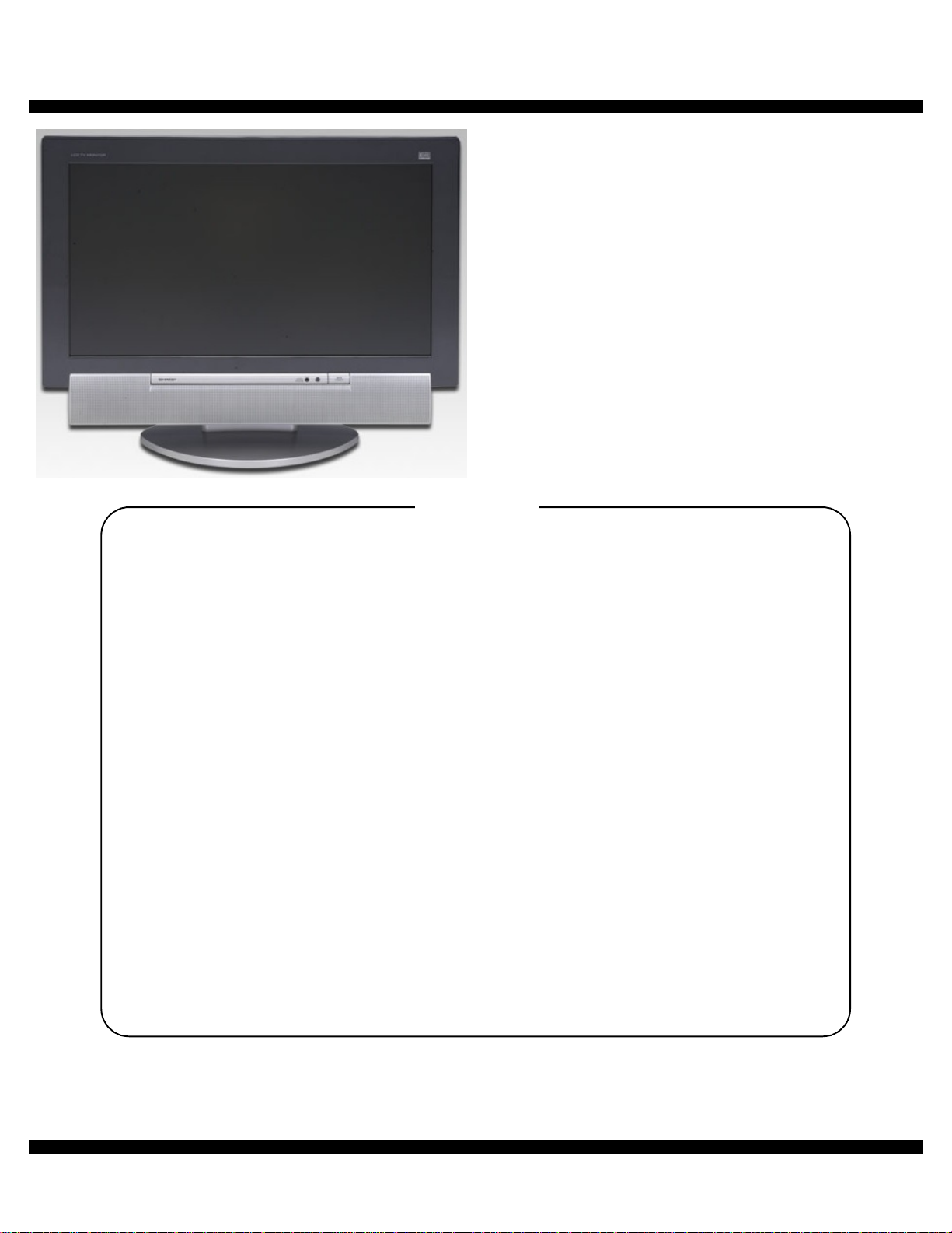
LCD MONITOR
IT-23M1U
CHAPTER 2. CONNECTION, ADJUSTMENT,
OPERATION, AND FUNCTIONS. . . . . . . . . . . . . . . . . . . . .2 - 1
CHAPTER 3. DISASSEMBLY AND ASSEMBLY. . . . . . . . . . . . . . . . . . . .3 - 1
CHAPTER 4. TROUBLE SHOOTING . . . . . . . . . . . . . . . . . . . . . . . . . . . .4 - 1
CHAPTER 5. BLOCK DIAGRAM . . . . . . . . . . . . . . . . . . . . . . . . . . . . . . . .5 - 1
CHAPTER 6. CIRCUIT DIAGRAM. . . . . . . . . . . . . . . . . . . . . . . . . . . . . . .6 - 1
CHAPTER 7. PWB LAYOUT . . . . . . . . . . . . . . . . . . . . . . . . . . . . . . . . . . .7 - 1
Parts mark ed w ith "!" are important for maintaining the safety of the set. Be sure to replace these parts with specified
ones for maintaining the safety and performance of the set.
SHARP CORPORATION
This document has been pub lished to be used
for after sales service only.
The contents are subject to change without notice.
Page 2
CHAPTER 1. OUTLINE OF THE PRODUCT, NOMENCLATURE AND FUNCTION
1. SPECIFICATIONS
Product specifications Dimensions (Units: mm)
Dot
frequency
90
223
Ana-
log
oo
oo
oo
o
oo
oo
oo
oo
oo
oo
o
o
oo
oo
o
oo
o
o
o
Model name IT-23M1U
LCD display 23" TFT LCD module
Actual display size 23.0" (58.3 cm) measured diagonally
Resolution (max.) 1366 x 768
Displayable colors (max.) Approx. 16.77 million colors (8 bit)
Dot pitch (H x V) 0.372 mm x 0.372 mm
Brightness (max.) 500 cd/m
Contrast ratio 550 : 1
Angle of visibility Left-right 176° ; up-down 176°
Screen display size (H x V)
Video signal Analog : Analog RGB (0.7 Vp-p) [75 Ω]
Sync signal Separate Sync (TTL level : +/-),
Video signal format NTSC
Expansion compensation Digital scaling
Plug & Play VESA DDC2B compatible
Power management VESA: based on DPMS
Speaker output 5 W + 5 W
Input terminals Computer signal:
Receivable
TV channels
Headphone terminal Mini stereo jack (φ3.5 mm)
Screen tilt Upward approx. 0° -20°;
Screen swivel Approx. 90° from left through right
Power supply 100 VAC - 240 VAC, 50/60 Hz
Temperature of
operating environment
Power consumption 95 W
(The screen brightness deteriorates over time.
Constant brightness cannot be maintained.)
(contrast ratio > 10)
508.2 mm x 285.7 mm (20.01" x 11.25")
Digital : DVI standard based on 1.0
Sync on Green,Composite Sync (TTL level:+/-)
(Enlarges VGA/SVGA/XGA etc.
[Enlarged display (full screen, Fixed aspect
ratio)]
• 1:1 display is not possible.
DVI : based on DMPM
Computer audio :
Video image : RCA pin x 2
Component image : x 1
S-video image : x 1
Audio input terminal: RCA pin (L/R x 2)
VHF : 2 through 13; UHF : 14 through 69;
Cable : 1 through 125
downward approx. 0° -5°
(Uses special AC adapter, type NL-A72J of
Sharp Corporation)
5°C - 35°C (41°F - 95°F)
5.5 W in power-saving mode
*
Dimensions (W x D x H) Approx. 589 mm x 223 mm x 479 mm
Weight Approx. 13 kg; 28.7 lb.
(Approx. 23.2" x 8.8" x 18.9")
(excluding signal cable and AC adapter)
Approx. 10.2 kg; 22.5 lb. (excluding stand)
2
to full screen size.)
Analog: Mini D-sub 15 pin (3 rows) x 1
Digital : DVI-D 24 pin x 1
Mini stereo jack (φ3.5 mm ) x 1
*
; 5.5 W in standby;
When "BRIGHT MODE"is set to "B RIGHT ".
62 W in "DARK1"and 52 W in "DARK2".
(Uses special AC adapter)
589
431
479
319
• PC analog signal cable : approx. 1.8 m (5.9 ft.)
• PC audio cable : approx. 1.8 m (5.9 ft.)
• Antenna cable : approx. 4 m (13.1 ft.)
• Digital signal cable,
NL-C04J (purchased separately) : approx. 2.0 m (6.6 ft.)
• Special AC adapter :
Approx. 1.8 m (5.9 ft.)
Dimensions (W x D x H)
Approx. 170 mm x 85 mm x 40 mm
(Approx. 6.7" x 3.3" x 1.6")
Note: As a part of our policy of continuous improvement,
SHARP reserves the right to make design and specification
changes for product improvement without prior notice.
The performance specification figures indicated are nominal
values of production units. There may be some deviations from
these values in individual units.
Relevant signal timings (PC mode)
Screen resolution Hsync Vsyn
VESA 640 x 480
800 x 600
1024 x 768
Wide 848 x 480
1280 x 720
1280 x 768
1360 x 768
US text 720 x 400
Power
Macintosh
series
• Recommended resolution is 1360 x 768, 1280 x 768 or 1024 x 768.
• All are compliant only with non-interlaced.
• Frequencies for Power Macintosh are reference values.
To connect, another adapter ( commerciall y avai labl e) may be re quired.
640 x 480
832 x 624
1024 x 768
31.5kHz 60Hz 25.175MHz
37.9kHz 72Hz 31.5MHz
37.5kHz 75Hz 31.5MHz
35.1kHz 56Hz 36.0MHz
37.9kHz 60Hz 40.0MHz
48.1kHz 72Hz 50.0MHz
46.9kHz 75Hz 49.5MHz
48.4kHz 60Hz 65.0MHz
56.5kHz 70Hz 75.0MHz
60.0kHz 75Hz 78.75MHz
31.1kHz 60Hz 33.3MHz
44.7kHz 60Hz 74.4MHz
47.986kHz 60Hz 71.0MHz
60.15kHz 75Hz
47.7kHz 60Hz 84.7MHz
31.5kHz 70Hz 28.3MHz
35.0kHz 66.7Hz 30.2MHz
49.7kHz 74.6Hz 57.3MHz
60.2kHz 75Hz 80.0MHz
102.977MHz
Digi-
tal
-
-
-
-
-
-
-
IT-23M1U OUTLINE OF THE PRODUCT, NOMENCLATURE AND FUNCTION
1 – 1
Page 3
• For digital connection, the monitor can be connected to a computer
with a DVI-compatible output terminal (DVI-D 24 pin or DVI-I 29 pin).
(Depending on the type of computer to be connected, the display may
not work correctly.)
• If the monitor is receiving timing signals that are not compatible,
"OUT OF TIMING" will appear. Follow your computer's instruction
manual to set the timing so that it is compatible with the monitor.
• If the monitor is not receiving any signal (synch signal), "NO SIGNAL"
will appear.
The analog RGB input connector pin
(Mini D-sub connector with 15 pins)
No. Funct i on No. Function
1 Red video signal input 9 +5V
2 Green video signal input 10 GND
3 Blue video signal input 11 N.C.
4 N.C. 12 DDC data
5 GND 13 For Hsync signal input
6 For red video signal GND 14 For Vsync signal input
7 For green video signal GND 15 DDC clock
8 For blue video signal GND
The analog RGB input connector pin
(DVI-D connector with 24 pins)
Power management
The monitor is based on the VESA DPMS and the DVI DMPM standards.
To activate the power management function, the video card and the
computer used with it must also conform to these standard.
DPMS: Display Power Management Signaling
DPMS mode Screen
ON Display on 95 W Yes Yes
STANDBY
SUSPEND Yes No
OFF No No
DMPM: Digital Monitor Power Management
DPMS mode Screen
ON Display on 95 W
OFF Display off 5.5 W
Display off 5.5 W
Power
consumption
Power
consumption
H-sync V-sync
No Yes
DDC (Plug & Play)
This monitor supports the VESA DDC (Display Data Channel) standard.
DDC is a signal standa rd for carryi ng out Pl ug & Play functions on the monitor or PC. It transfer s information such as degree of resoluti on between the
monitor and PC. You can use this funct ion if your PC is DDC comp liant an d
if it is set so that it can detect t he Plug & Play mon itor.
There are many varieties of DDC due to the differences between systems. This monitor works with DDC2B.
No. Funct i on No. Function
1 TMDS data 2- 13 N.C.
2 TMDS data 2+ 14 +5V
3 TMDS data 2/4 shield 15 GND
4 N.C. 16 Hot plug detection
5 N.C. 17 TMDS data 06 DDC clock 18 TMDS data 0+
7 DDC data 19 TMDS data 0/5 shield
8N.C. 20N.C.
9 TMDS data 1- 21 N.C.
10 TMDS data 1+ 22 TMDS clock shield
11 TMDS data 1/3 shield 23 TMDS clock +
12 N.C. 24
TMDS clock -
IT-23M1U OUTLINE OF THE PRODUCT, NOMENCLATURE AND FUNCTION
1 – 2
Page 4
2. PRODUCT DESCRIPTION
Main unit
INPUT
MENU
2
BRIGHT
ENTER/
MODE
CH
VOL/BRIGHT
1
Speakers
1
Control buttons
2
Headphone terminal
3
Remote sensor window
4
Power LED
5
3 4
5 6
Green : in use
Red : in standby mode
Orange : in power-saving mode (only for PC mode)
Off: power off
MAIN POWER but to n
6
Power input terminal
7
PC digital RGB input terminal (DVI-D 24 pin)
8
PC analog RGB input terminal (mini D-sub 15 pin)
9
PC audio input terminal
F
Lug-hole for cable clamp
G
Antenna input terminal
H
Video input terminal
I
Audio input terminal - Left
J
Audio input terminal - Right
K
S-video input terminal
L
Video input terminal
M
Audio input terminal - Left
N
Audio input terminal - Right
O
Component input terminals
P
Ventilation openings: Never block the ventilation openings as this
A
AV-IN1
AV-IN2
may lead to overhe ating inside t he monitor
and result in malfunction.
Security lock anchor: By connecting a security lock (commercially
B
available) to the security lock anchor, the monitor is fixed so that it cannot be t ransport ed.
The security slot works in conjun ction with Ken sington Micro Saver Security Systems.
7 8
A
9
10 11 12
A
Remote control
13
14
15
16
17
18
19
20
B
POWER button
1
FREEZE button
2
SLEEP butt on
3
4 b c e d
BRIGHT MODE button
5
DISPLAY button
6
CC (Closed Caption) button
7
Channel buttons
8
Dolby Virtual button
9
Input buttons (PC, TV, AV1, and AV2)
F
VIEW MODE button
G
MULTI button
H
MENU button
I
BRIGHT button
J
MUTE button
K
MTS (Multi ch TV Sound) button
L
VOL buttons
M
CH (channel) buttons
N
FLASHBACK b utton
O
1
2
3
4
5
6
7
8
buttons and ENTER button
POWER
FREEZE
SLEEP
BRIGHT
MODE
DISPLAY
PC AV2AV1TV
VIEW MODE
MULTI
ENTER
CC MTS MUTE
Virtual
MENU
BRIGHT
VOL
CH
FLASHBACK
9
10
11
12
13
14
15
16
17
18
19
Removing the cover
Be careful not to pinch the cables.
Replacing the cover
2
1
2
IT-23M1U OUTLINE OF THE PRODUCT, NOMENCLATURE AND FUNCTION
1
1 – 3
Page 5
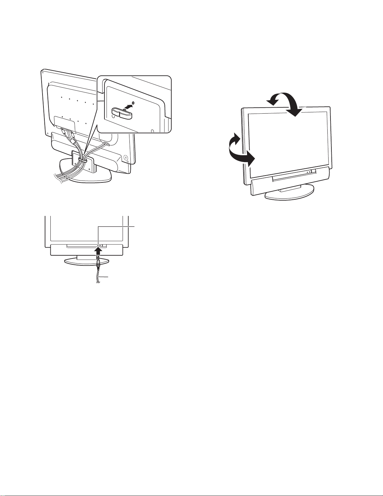
Cable clamp
Use the supplied cable clamp to secure the cables connected to the terminals.
Caution: When adjusting the viewing angle, cables may be pulled.
Therefore, ensure that the cables have sufficient slack.
Using headphones (commercially available)
You can connect headphones (commercially available) to the monitor.
Angle adjustment
Adjust to an easy to view angle.
Caution:
• Be sure to hold both sides of the monitor when adjusting the viewing angle. The LCD panel used in this monitor is made of glass.
Pressure from hands on the LCD panel could cause damage.
• Be careful not to allow your fingers to be pinched.
approx. 20˚
approx. 5˚
approx.
45˚
approx. 45˚
Headphone
terminal
Headphones
Note:
• When headphones are connected, no sound can be heard from
the monitor speakers.
• When headphones are connected, the Virtual Dolby Surround
function (see page E27) cannot be used.
• When headphones are connected, the AUDIO ADJUST menu
(see pages E34 and E51) cannot be adjusted.
IT-23M1U OUTLINE OF THE PRODUCT, NOMENCLATURE AND FUNCTION
1 – 4
Page 6
CHAPTER 2. CONNECTION, ADJUSTMENT, OPERATION, AND FUNCTIONS
1. CONNECTION
1-1. Connecting the monitor to a computer
Caution:
• When connecting, ensure that the monitor and all the equipment
you are connecting to it are switched off.
• Be careful not to over bend the cable or add extension cords as this
could lead to a malfunction.
Note:
• When using the monitor with an analog connection, perform an
automatic screen adjustment under the following conditions:
• Using the monitor for the first time.
• After having changed the system settings during use.
• When using the monitor with a digital connection, automatic screen
adjustment is unnecessary.
• Depending on the computer or OS, you may have to install the setup information for the monitor.
• When connecting to a notebook and the notebook computer's
screen is set so that it is displaying at the same time, the MS-DOS
screen may not be able to display properly. In this case, change
the settings so that only the monitor is displaying.
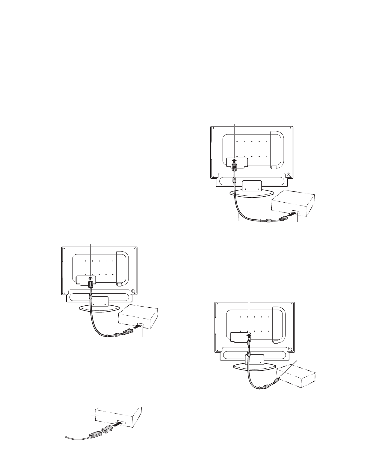
Analog connection
Connect the supplied PC analog signal cable to the analog RGB output
terminal of the computer.
For information on removing/replacing the terminal cover.
PC analog RGB input terminal
Digital connection
Connect the separately-sold digital signal cable (model name: NLC04J) to the digital RGB output terminal of the computer.
For information on removing/replacing the terminal cover.
• The monitor has an input terminal for connecting to a computer with a
DVI-compatible output terminal (DVI-D 24 pin or DVI-I 29 pin).
(Depending on the type of computer to be connected, the display may
not work correctly.)
PC digital RGB input terminal
Digital signal cable
(separately-sold)
• Paying attention to the connector direction, firmly insert the signal
cable straight into theconnector, and then tighten the screws at both
ends.
Digital RGB
output terminal
PC analog signal cable
(supplied)
Analog RGB
output terminal
• Paying attention to the connector direction, firmly insert the signal
cable straight into the connector, and then tighten the screws at both
ends.
If connecting to a D-sub 15 pin 2 row Apple P ower Macint osh, attach a
Macintosh conversion adapter (commercially available) to the analog
signal cable.
Power Macintosh
Macintosh conversion adapter
Connecting the audio cable
Connect the supplied PC audio cable to the audio output terminal of the
computer.
PC audio input terminal
Audio
output
terminal
PC audio cable
(supplied)
IT-23M1U CONNECTION, ADJUSTMENT, OPERATION, AND FUNCTIONS
2 – 1
Page 7
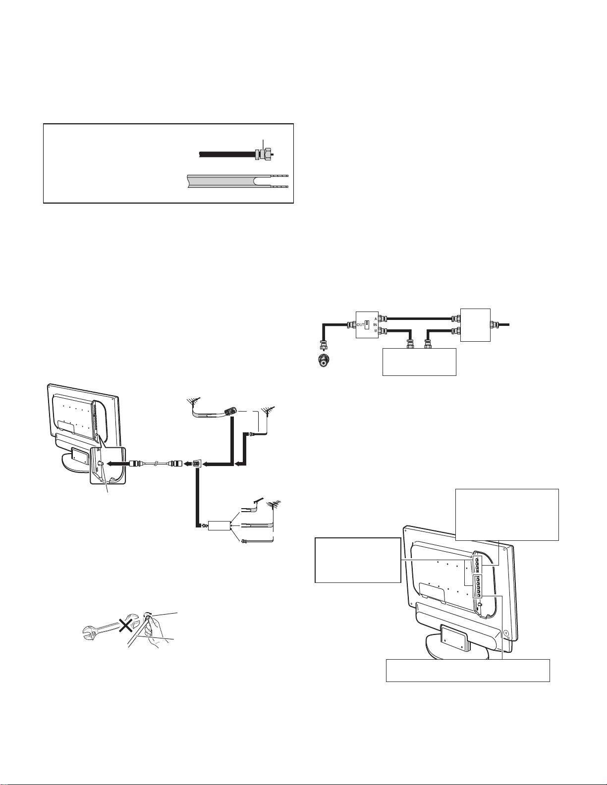
1-2. Connecting the monitor to a home antenna terminal
Caution: When connecting, ensure that the monitor is switched off.
The antenna requirements for good color television reception are more
important than those for black & white television reception.
For this reason, a good qualit y outd oor ant enna is st rongly re commende d.
The following is a brie f ex planat i on of t he type of connect i ons that are
provided with the various antenna systems.
1. A 75-ohm system is generally a
round cable with F-type connect or
F-type connector
that can easily be attached t o a terminal without tools (not sup plied ).
2. A 300-ohm system is a flat "twin-
75-ohm coaxial cable (round)
lead" cable that can be att ached to
a 75-ohm terminal through a 30075-ohm adapter (not supplied) .
300-ohm twin-lead cable (flat)
Note:
• The 75-ohm coaxial cable is recommended.
• TV memory for channels is empty at shipment.
To receive channels, use the CHANNEL SETTING menu.
Outdoor antenna connection
• Use one of the following two diagrams if you connect an outdoor
antenna.
A: Using a VHF/UHF combination outdoor antenna.
B: Using separate VHF and/or UHF outdoor antennas.
•
Connect the outdoor antenna cable lead-in to t he ANT (antenna input)
terminal on the left side of the monitor.
A. Combination VHF/UHF Antenna
VHF/UHF
antenna
Home Antenna
terminal (75-ohm)
Antenna cable
(supplied)
Antenna input terminal (ANT)
300/75-ohm
adapter
(not supplied)
300-ohm
twin-lead
B. Separate VHF and/or
Combiner
(not supplied)
IN
OUT
or
coaxial cable
UHF Antennas
antenna
300-ohm
twin-lead
300-ohm
twin-lead
75-ohm
coaxial cable
Caution: When connecting the RF cable to the monitor, do not tighten
F-type connector with tools. If tools are used, it may cause
damage to your monitor. (The breaking of internal circuit, etc.)
F-type connector
75-ohm
UHF
VHF/UHF
antenna
VHF
antenna
or
Cable TV (CATV) connection
• A 75-ohm coaxial cable connector is built into the set for easy
hookup. When connecting the 75-ohm coaxial cable to the set, screw
the 75-ohm cable to the ANT (antenna input) terminal.
• Some cable TV companies offer "premium pay channels". Since the
signals of these premium pay channels are scr ambled, a cable TV
converter/descrambler is generally provided to the subscriber by the
cable TV company. This converter/descrambler is necessary for normal viewing of the scrambled channels. (Set your monitor to channel
3 or 4, typically one of these channels is used. If this is unknown, consult your cable TV company.) For more specific instructions on installing cable TV, consult your cable TV company. One possible method
of utilizing the converter/descrambler provided by your cable TV company is explained below.
Please note: An RF switch provided with two inputs (A and B) is
required (not supplied).
"A" position on the RF switch (not s upplied) :
You can view all unscramble d ch annels by usin g the monit or's channel buttons.
"B" position on the RF switch (not s upplied) :
You can view the sc ramb led chann els vi a the c on verte r/de scr amble r
by using the converter's channel keys.
RF switch (not supplied)
OUT
Cable TV converter/
descrambler
(not supplied)
IN
Two-set
signal
splitter
(not
supplied)
Cable TV Line
Note: Consult your SHARP Dealer or Service Center for the type of
splitter, RF switch or combiner that might be required.
1-3. Connecting the monitor to AV equipment
Caution: E nsure that the monitor and all the equipment you are con-
necting to it are switched off before you begin.
Examples of equipment you can connect
Equipment with
S-video output terminals
VCRsVideo cameras
Home video game systems
Videodisc players
VCRs
Video cameras
Home video game systems
Videodisc players
DVD players etc.
DVD players etc.
75-ohm coaxial cable
IT-23M1U CONNECTION, ADJUSTMENT, OPERATION, AND FUNCTIONS
Equipment with component output terminals
DVD players etc.
2 – 2
Page 8
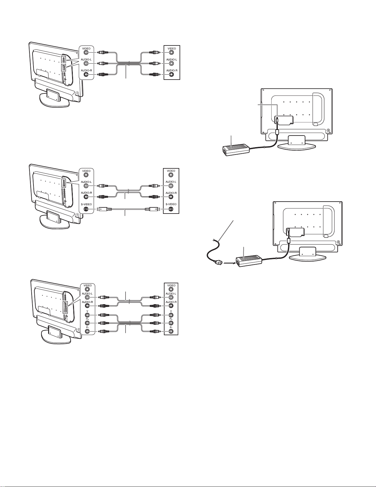
AV equipment with video output terminals
Left side of the monitor
AV-IN1 or AV-IN2
(Yellow) (Yellow)
(White) (White)
(Red) (Red)
RCA pin cable (commercially available)
VCR etc.
Note: When you are using the video input terminal, do not connect
cables to the S-video input terminal and the component input terminals.
AV equipment with S-video output terminals
Left side of the monitor
AV-IN1
VCR etc.
1-4. Connecting the monitor to a power source
Caution:
• When connecting, ensure that the monitor is switched off.
• Always use the AC adapter that came with the monitor.
• Be careful not to over bend the cable or add extension cords as this
could lead to a malfunction.
1. Connect the AC adapter to the power input terminal.
Power input terminal
AC adapter (supplied)
(White) (White)
(Red) (Red)
RCA pin cable (commercially available)
S-video cable (commercially available)
Note: When you are using the S-video input terminal, do not connect
the cable to the video input terminal.
AV equipment with component output terminals
Left side of the monitor
AV-IN2
RCA pin cable (commercially available)
(White) (White)
(Red) (Red)
(Green) (Green)
(Blue) (Blue)
(Red) (Red)
Component video cable
(commercially available)
Note: When you are using the co mponent input terminals, do not con-
nect the cable to the video input terminal.
Connecting the monitor to a power source
DVD player etc.
2. Plug the power cord into the AC adapter and then place the power
plug into an AC outlet.
Power cord (supplied)
AC outlet
AC adapter
(supplied)
IT-23M1U CONNECTION, ADJUSTMENT, OPERATION, AND FUNCTIONS
2 – 3
Page 9
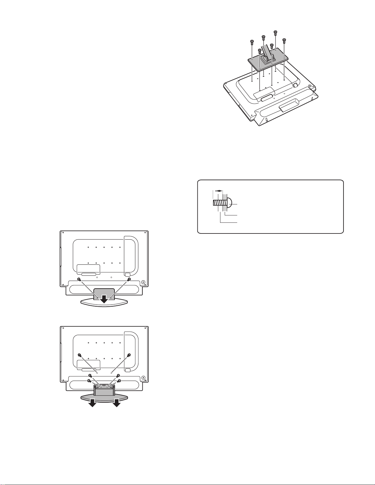
1-5. Instructions for attaching a VESA compliant arm
An arm or stand based on the VESA standar d (comme rcially available)
can be attached to the monitor.
Procurement of the arm or stand is at the customer's discretion.
Arms or stands able to be used
Attachments must satisfy the following.
• Compatible with the VESA standard.
• The s ix screw ho les on the s ection to be attached have a gap of 100
mm between them.
• Not be likely to fall off or break off after being attached to the monitor.
How to attach the arm or stand
Be careful not to over bend the cable or add extension cords as this
could lead to malfunction.
While following these instructions, please also refer to t he installation
instructions in the operation manual included with the arm or stand.
Caution: Be careful not to get your fingers pinched between the display
and stand nor to let the stand drop. These could lead to injury.
1. Remove the cables.
5. Attach the arm to the monitor with the six screws.
Note:
• The screws used to attach the arm should be M4 screws with a
length of 6 mm - 8 mm (0.24" - 0.31") protruding from the surface to
be attached.
Using different screws could cause the monitor to fall off or to be
internally damaged.
6 mm - 8 mm (0.24" - 0.31")
2. Spread out a soft cloth on a suitable horizontal surface. Being careful not to damage the monitor, gently lay the monitor on it displayside down.
3. Remove the two screws and then remove the re ar cover of the stand.
4. Remove the six screws and then remove the stand f rom the moni tor.
Screw used to attach arm
Arm
Part of monitor to which arm is
attached
Notes:
• The stand is specially made for use with this monitor. Once having
removed the stand, never attempt to at tach i t to anot her equi pmen t.
• Once having removed the screws, store them together with the stand
and if the stand is ever re-att ached be sur e t o use the or igina l screw s.
Using different screws could le ad to a mal functio n.
IT-23M1U CONNECTION, ADJUSTMENT, OPERATION, AND FUNCTIONS
2 – 4
Page 10
2. ADJUSTMENT
2-1. ADJUSTMENT METHOD (PC MODE)
* Press the PC button to select PC mode.
1) Resetting all adjustment v
alues
Press the above two buttons at same time, and while turn the power on.
2) Adjustment lock function
MENU
(Press the button and select "BRIGHT" or "VOLUME".)
Power ON
MENU
3) DOLBY VIRTUAL
DOLBY VIRTUAL
VIEW MODE
4)
VIEW MODE
TI SCREEN DISPLAY
MUL
5)
MULTI
PIP POSITION
6)
ON/OFF
CHANGE
CHANGE
While displaying the PIP window, you can also set this item directly using
the bcde buttons, instead of the adjustment screen.
7)
Adjustment pattern
MENU
MENU
END
c
c
ENTER
ENTER
ADJUSTMENT
(Analog)
GAIN
CONTROL
ENTER
ENTER
(Analog)
c
ENTER
AUDIO
ADJUST
*
If you do not press any buttons for about 30 seconds
while in a menu screen, the settings you made up to
that point will be applied and the screen will
automatically disappear.
AUTO
CLOCK
PHASE
H-POS
V-POS
RESET
AUTO
BLACK LEVEL
CONTRAST
RESET
TREBLE
BASS
BALANCE
DOLBY VIRTUAL
(e d buttons)
(e d buttons)
(e d buttons)
(e d buttons)
(e d buttons)
(e d buttons)
(e d buttons)
(e d buttons)
(e d buttons)
(e d buttons)
c
ENTER
COLOR
CONTROL
COLOR CONTROL
WHITE BALANCE
(e d buttons)
d
(COOL, STD, WARM, USER)
RESET
c
ENTER
MODE
SELECT
VIEW MODE
480 LINES
768 LINES
SOUND
d
(e d buttons)
(e d buttons)
(e d buttons)
(e d buttons)
c
R-CONTRAST
c
G-CONTRAST
c
B-CONTRAST
(e d buttons)
(e d buttons)
(e d buttons)
SCALING
RESET
c
ࠨ
MULTI
SCREEN
MULTI SCREEN DISPLAY
PIP SIZE
PIP POSITION
PC POSITION
SUB SOURCE
SOUND
(e d buttons)
(e d buttons)
(e d buttons)
(e d buttons)
(e d buttons)
(e d buttons)
RESET
IT-23M1U CONNECTION, ADJUSTMENT, OPERATION, AND FUNCTIONS
2 – 5
Page 11
2-2. ADJUSTMENT ITEM LIST (PC MODE)
BUTTON
MENU
MENU 1:
ADJUSTMENT
MENU 2:
GAIN CONTROL
MENU 3:
AUDIO ADJUST
MENU 4:
WHITE BALANCE
MENU 5:
MODE SELECT
ITEM ADJUSTMENT DESCRIPTION
MANUAL CLOCK 0~255 CLOCK: Adjust so that vertical flicker noise is not emitted.
PHASE 0~255 PHASE: Adjust so that horizontal flicker noise is not emitted.
H-POS Indefinite H-POS (horizontal positioning) and V-POS (vertical positioning)
V-POS Indefinite
AUTO Automatic screen adjustment
MANUAL BLACK LEVEL 0~100 BLACK LEVEL: Total screen brightness can be adjusted
CONTRAST 0~100 CONTRAST: While watching the color pattern, adjustments
AUTO GAIN CONTROL Menu
TREBLE -30~0~+30 Adjusts high-pitch sounds.
BASS -30~0~+30 Adjusts low-pitch sounds.
BALANCE -30~0~+30 Adjusts the balance between the right and left sp eakers.
DOLBY VIRTUAL ON/OFF Tur ns the Virt ual Dolb y Surroun d fun cti on "ON" or "O FF".
COLOR MODE STD, sRGB,
WHITE BALANCE COO L • S T D •
VIEW MODE NORMAL, FULL Selects the screen size.
480 LINES 640, 848 Specifies the horizontal resolution of a 480-line screen.
768 LINES 1024, 1280, 1360 Specifie s the horizontal resolution of a 768-line screen.
SOUND
SCALING 1~4
LANGUAGE
IT-23M1U CONNECTION, ADJUSTMENT, OPERATION, AND FUNCTIONS
VIVID
WARM (5 le ve ls) ,
USER R • G • B:
0~255
PC, TV, AV1, AV2,
2 – 6
buttons)
e d
(
(
buttons)
e d
To center the screen image within the boundaries of the screen,
adjust the left-right (H-POS) values and the up-down (V-POS) values. (
Options in the ADJUSTMENT Menu can be adjusted automatically
(CLOCK, PHASE, H-POS V-POS).
AUTO: Every menu option is automatically adjusted using the
You can also set this item directly using the re mote c ontrol, i nstead
of the adjustment screen.
Selects the color tone.
WHITE BALANCE Menu
COOL : Color tone bluer than standard
STD : Color tone standard setting
WARM : Color tone redder than standard
USER
NORMAL :
FULL :
(For analog signals)
640 : 640 x 480 dot mode
848 : 848 x 480 dot mode
(For analog signals)
1024 : 1024 x 768 dot mode
1280 : 1280 x 768 dot mode
1360 : 1360 x 768 dot mode
Selects the audio to listen to while displaying the computer screen.
When the PIP/SPLIT window is displayed, the audio set by "SOUND" in
the MULTI SCREEN menu takes precedence.
When "STATUS" in the V-CHIP BLOCK menu is "ON",
TV/AV-IN SOUND is not available in PC mode.
Adjusts the image to optimum sharpness when it is enlarged.
Selects the language (English, French or Spanish) on the screen.
buttons)
e d
while watching the color pattern. (
can be made so that all graduations appear.
(
buttons)
e d
Auto Gain Control function.
STD : Displays images using the original color tone of the LCD
sRGB : sRGB is an international standard for color rep
VIVID : Displays images in vivid primary colors.
R-CONTRAST:
G-CONTRAST:
B-CONTRAST:
monitor.
resentation defined by the IEC
International Electrotechnical Commission).
Colors are converted by taking into account the
liquid crystal's characteristics and thereby
represent color tone close to the original image.
• : Color tone slightly bluer than standard
• : Color tone slightly redder than standard
button for blue-green, d button for red
e
button for purple, d button for green
e
button for yellow, d button for blue
e
Displays the image without changin g it s as pect ratio. When
the image's resolution is lowe r tha n 1024 x 768, the image
is expanded.
Expands the image so that it fills the screen.
(The aspect ratio may change.)
You can also set this item directly using the remote control,
instead of the adjustment screen.
e d
buttons)
Page 12
BUTTON ITEM ADJUSTMENT DESCRIPTION
MENU 6:
MULTI SCREEN
MULTI SCREEN
DISPLAY
OFF, PIP, SPLIT Designates whether the com puter's sc reen and TV or v ideo
images are displayed simultaneously.
OFF:
PIP: The TV or video image appears in a small window
(PIP window) on the computer screen.
SPLIT: The computer's screen and the TV or video image appear
side by side in two split windows.
You can also set this item directly using the remote control,
instead of the adjustment screen.
PIP SIZE Changes the size of the PIP window.
PIP POSITION Adjusts the position of the PIP window.
] [c] buttons.
To move up and down, press the [
To move left and right, press the [
b
] [d] buttons.
e
While displaying the PIP window, you can also set this item directly
using the remote control, instead of the adjustment screen.
PC POSITION CENTER, LEFT Designates the position of the computer screen when the PIP win-
dow is displayed.
This item is enabled when the computer's "VIEW MODE" is set to
"NORMAL".
IT-23M1U CONNECTION, ADJUSTMENT, OPERATION, AND FUNCTIONS
2 – 7
Page 13
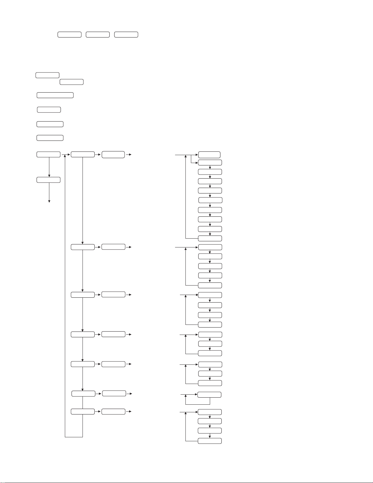
2-3. ADJUSTMENT METHOD (TV/AV MODE)
Press the
* /
*
If you do not press any buttons for about 30 seconds while in a menu screen, the settings you made up to
TV
AV1
AV2
/
button to select TV or AV mode.
that point will be applied and the screen will automatically disappear.
1) Resetting all adjustment values
Press the above two buttons at same time, and while turn the power on.
2) Adjustment lock function
MENU
(Press the button and select "BRIGHT" or "VOLUME".)
Power ON
MENU
3) DOLBY VIRTUAL
DOLBY VIRTUAL
ON/OFF
4) VIEW MODE
VIEW MODE
CHANGE
5) SLEEP TIMER
SLEEP TIMER
to change the setting.
(The time changes in the following order each time you press the button)
6) CC/TEXT
CC/TEXT
7)
Adjustment pattern
MENU
MENU
END
to change the setting. (The setting changes in the following order:)
c
c
c
c
c
c
ENTER
ENTER
ENTER
ENTER
ENTER
ENTER
GAIN CONTROL
AUDIO ADJUST
CHANNEL SETTING
(TV mode only)
SCREEN ADJUST
MODE SELECT
CLOSED CAPTION
ENTER
c
c
c
c
c
c
c
c
c
c
c
c
c
c
c
c
c
c
c
c
c
c
c
c
c
AUTO
CONTRAST
BLACK LEVEL
COLOR
TINT
SHARPNESS
FLESH TONE
VIDEO SELECT
WHITE BALANCE
RESET
TREBLE
BASS
BALANCE
DOLBY VIRTUAL
RESET
AIR/CABLE
CABLE MODE
CHANNEL SEARCH
CHANNEL MEMORY
VIEW MODE
POSITION
RESET
SLEEP TIMER
LANGUAGE
RESET
CC/TEXT
(e d buttons)
(e d buttons)
(e d buttons)
(e d buttons)
(e d buttons)
(e d buttons)
(e d buttons)
(e d buttons)
(e d buttons)
(e d buttons)
(e d buttons)
(e d buttons)
(e d buttons)
(e d buttons)
(e d buttons)
(e d buttons)
(e d buttons)
(e d buttons)
(e d buttons)
(e d buttons)
(e d buttons)
(e d buttons)
(e d buttons)
c
ENTER
V-CHIP BLOCK
IT-23M1U CONNECTION, ADJUSTMENT, OPERATION, AND FUNCTIONS
c
c
c
c
MPAA
TV GUIDELINES
STATUS
RESET
(e d buttons)
(e d buttons)
(e d buttons)
2 – 8
Page 14
2-4. ADJUSTMENT ITEM LIST (TV/AV MODE)
BUTTON ITEM ADJUSTMENT DESCRIPTION
MENU MENU 1:
VIDEO
ADJUSTMENT
MENU 2:
AUDIO ADJUST
MENU 3:
AUDIO ADJUST
(TV mode only)
MENU 4:
SCREEN ADJUST
MENU 5:
MODE SELECT
MENU 6:
CLOSED CAPTION
MENU 7:
V-CHIP BLOCK
CONTRAST Adjusts contrast.
BLACK LEVEL Adjusts the overall brightness of the screen.
COLOR Adjusts the color depth.
TINT Adjusts the color tone.
SHARPNESS Adjusts the image quality.
FLESH TONE Adjusts the flesh tone color.
VIDEO SELECT
Selects the type of image to display improving the quality of the images.
This adjustment is invalid for images from the S-video and
component input terminals.
WHITE BALANCE Adjusts the color temperature.
STD : Standard setting for color tone.
WARM : Color tone redder than standard.
TREBLE
BASS
BALANCE
DOLBY VIRTUAL
-30~0~+30 Adjusts high-pitch sounds.
-30~0~+30 Adjusts low-pitch sounds.
-30~0~+30 Adjusts the balance between t he right and left spea kers.
ON/OFF Turns the Virtual Dol by Surround fun ction "ON" or "OFF".
You can also set this item directly using the remote control,
instead of the adjustment screen.
AIR/CABLE
CABLE MODE
CHANNEL SEARCH
CHANNEL MEMORY
VIEW MODE
Sets the receiving mode broadcast (AIR) or cab le TV (CABLE).
Set this item when "AIR/CABLE" is set to "CABLE".
Sets available channels aut omati cally.
Sets channels manually.
Selects the screen size.
NORMALDisplays 4:3 aspect ratio TV images nor mall y.
WIDE :Expands 4:3 images horizontally to fill the entire screen
(16:9).
ZOOM1: Expands the image to fill the screen (16:9) with wide black
bands across the top and bottom such as letterbox format
movies.
ZOOM2: Can be used when "ZOOM1" cuts of f capti ons or t elops at
the top or bottom of the screen.
FULL : Returns images horizont all y reduce d fr om 16:9 to 4: 3 back
to 16:9 so they fill the entire screen.
You can also set this item directly using the remote control, instead of the
adjustment screen.
Depending on the type of data received or the video software used,
screen edges may be slightly cut off or the image may have a black border.
POSITION
Adjusts the position of the imag e.
V-POSITION : Adjusts the image's vertical posit ion.
H-POSITION : Adjusts the image's horizontal position.
RESET : Resets the image's position to the monitor's original
factory setting.
SLEEP TIMER
Specifies how many minutes until the moni tor switche s off (st andby) .
You can also set this item directly u sing t he remote control, instead of
the adjustment screen.
LANGUAGE
Selects the language (English, French or Spani sh) on the screen.
CC/TEXT Sets the CC/TEXT mode.
MPAA Sets whether MPAA block or unblock (-----).
TV GUIDELINES Sets whether TV GUIDELINES block or unblock (-----).
STATUS Sets whether the block setting st atus is ON or O FF.
When "STATUS" in the V-CHIP BLOCK menu is "O N",
TV/AV-IN SOUND is not available in PC mode.
IT-23M1U CONNECTION, ADJUSTMENT, OPERATION, AND FUNCTIONS
2 – 9
Page 15
2-5. ALL RESET
(1) RETURNED TO AN INITIAL VALUE SET VALUE
• ALL RESET
All the adjustment values except the custom mode (special sp ecification) are reset.
Press and hold down both the [Menu] button and the
1
[OK/BRIGHT] mode button on the system unit while pressing
the power supply button on the system unit, Hold the three buttons down until displaying on the screen as "ALL RESET".
After ALL RESET is completed, it starts.
2
• INITIALIZE (For service)
All the adjustment values including those of the custom mode
(special specifications) are reset.
Press and hold down both the [INPUT], [Menu] button and the
1
[
] button (VOL/BRIGHT) on the system unit while pressing the
d
power
supply button on the system unit, Hold the three buttons down
until displaying on the screen as "INITIALIZE".
After INITIALIZE is complete d , it st a r ts.
2
(2) Version display (for service)
1
Press and hold do wn bo th the [MENU] button and the [ d ] button (VOL/
BRIGHT) on the system unit while pressing the [POWER] button on the system unit, to turn on the power supply of the system. Hold the three butto ns
down until the version is displayed on screen.
The software version and checksum appears on screen.
2
Turn off the power supply of the system or terminate the display of
3
the version by pressing the [MENU] button on the system unit.
VERSION & CHECK SUM
VERSION : 1.01 (2004XXXX)
CHECK SUM : OK XX XX
CUSTOM MODE : OFF
2-6. IT-23M1 EDID Writing Procedure
[Tool target models]
IT-23M1
[Tool operating environment]
• Windows95/ Windows98/ Windows2000/ Windows XP
• The printer port I/O address is set to 378.
(Refer to the supplementary explanations.)
[Installing procedure]
(1) Create a folder of "c:\fg."
(2) Copy all the files in the launcher tool into c:\fg folder.
If there is already a launcher tool folder, use that folder.
(Use the launcher tool of the latest version.)
(3) Copy all the files in the EDID writing tool for servicing of the
IT-23M1 into c:\fg folder.
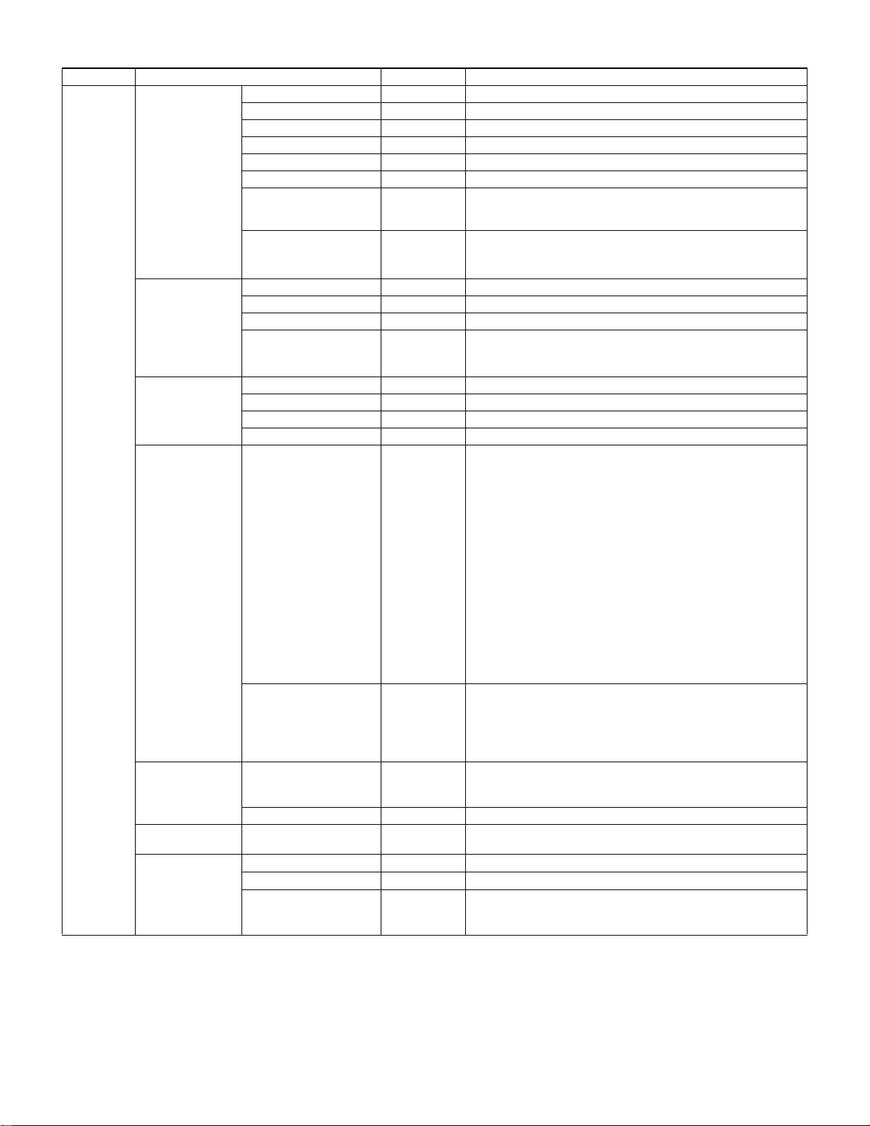
[Operating procedures]
(1) Connect the jig to the PC. (Refer to the connection diagram.)
(2) Execute c:\fg\launcher.exe.
(3) The window is displayed.
Select the target model in [Classification].
Select "XXXXXXXX (target model) write EDID" in [Process content].
After selection, click [EXECUTE].
(3) Aging (for service)
*
Make sure the signal cable is disconnected from the PC before starting this procedure.
1
Press and hold dow n th e [ENT ER/BR IG HT] but ton an d the [ e ] (VOL/
BRIGHT) button while pressing the [POWER] button of the system unit to turn
on the system. Hold down the three keys until the ageing menu appears on
screen.
2
The ageing menu is displayed on screen.
AGING TEST
AGING TEST1
3
AGING TEST2
button on system unit
[MENU]
[ENTER/BRIGHT]
[INPUT]
Ageing test 1:The screen is switched over in the following manner:
Ageing test 2:Every time the [
When turn off, press
3
button on system unit
buttons on system unit
DARK BLUE
BLUE3GREEN3RED3WHITE3 BLACK
the screen is switched over as follows:
WHITE3BLACK3RED3GREEN3BLUE3WHITE50%
3
DARK GREEN3DARK RED
buttons
[INPUT]
: Select options
: Execute the selected test.
: Terminate ageing menu.
3
3
] (VOL, BRIGHT) button is pressed,
d
.
Aging is not ended even if it shuts off the main power supply.
(4) The confirmation window to check the execution content is
displayed. If it is OK, press YES, if not, press NO. When NO is
pressed, the process returns to (3). When YES is pressed,
the process goes to the next step.
At this point, do not connect the jig to the monitor.
3
IT-23M1U CONNECTION, ADJUSTMENT, OPERATION, AND FUNCTIONS
2 – 10
Page 16
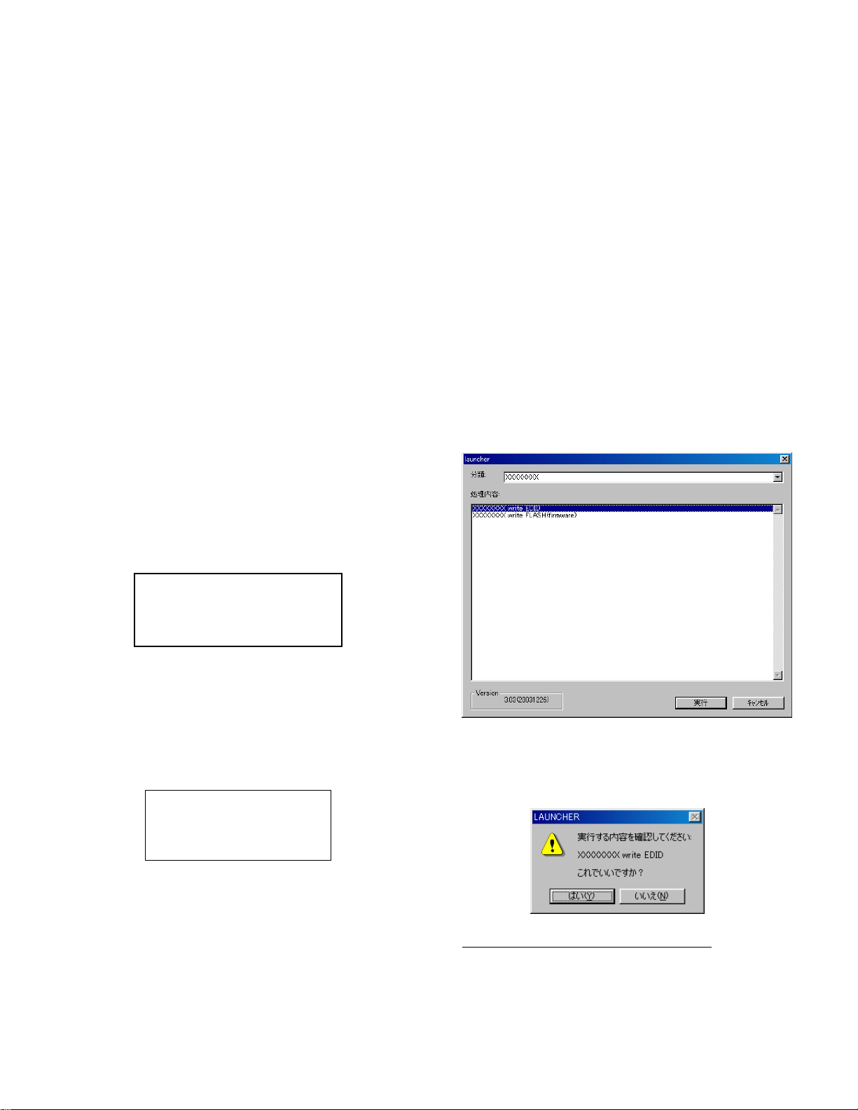
(5) When the following window is displayed, check the possible causes
below.
1. The jig and the PC are not connected properly.
2. The jig is already connected to the monitor.
Check the conne cti on, and p re ss OK bu tt on an d th en [ NEXT ] bu tto n.
(6) The following window is displayed. Connect the jib to the monitor.
Check the model name.
(10)When writing is normally completed or [Cancel] button is pressed
on the EDID error window, the process returns to the window of (7).
Then writing of another set can be executed.
(11)Press [POWER] button to turn off the power.
[Supplementary explanations]
• How to set the printer port I/O address to 378.
1. Open the control panel system.
2. Open the device manager tag, and check the display by type.
[Setting on the monitor side]
1 : Connect the RGB cable and the DVI-D cable to the monitor and
the jig.
2 : Press [POWER] key to supply power and wait until [No input
signal] is displayed.
(7) Enter the serial number with 10-key, and click [NEXT].
(8) The following window is displayed.
On this window, EDID writing and verifying are performed. When
the operation is interrupted halfway, connection may be wrong.
Check to confirm it.
When writing is completed, the window of item (6) is displayed.
Connect the jig to the following monitor.
Repeat EDID writing procedures from item (6) to the next monitor.
(9) When an error occur s in writing or verifying:
When an error occurs in writing or verifying, the above window is
displayed.
When [Retry ] bu tton is pres se d, E DID wri ting a nd ver ifying a re exe cute d
again. Norma l ly check the cable connection and press this button.
If an error still occurs in retry, pres s [Ca ncel] butt on. Whe n [Canc el] button is pres s e d, the next -step window is forcibly display ed.
However, note that EDID writing is not properly completed.
3. Click [+] on the left of [Port (COM/LPT)] to check to insure that there
is [Printer port (LPT1)]. (The printer port indication may be s lightly
different such as [ECP printer port (LPT1)].)
4. Open the printer port (LPT1) property.
5. Uncheck [Automatic setti ng is u sed.] and se lect [Basi c setting 0 000].
(If [I/O range] is already [0378 ? 037F], there is no need to change.)
• In the above descriptions on the writing procedures, the copy destination of the files is "c:\fg". However, any other folder may be acceptable as far as all the files are copied to that same folder on the hard
disk.
IT-23M1U CONNECTION, ADJUSTMENT, OPERATION, AND FUNCTIONS
2 – 11
Page 17
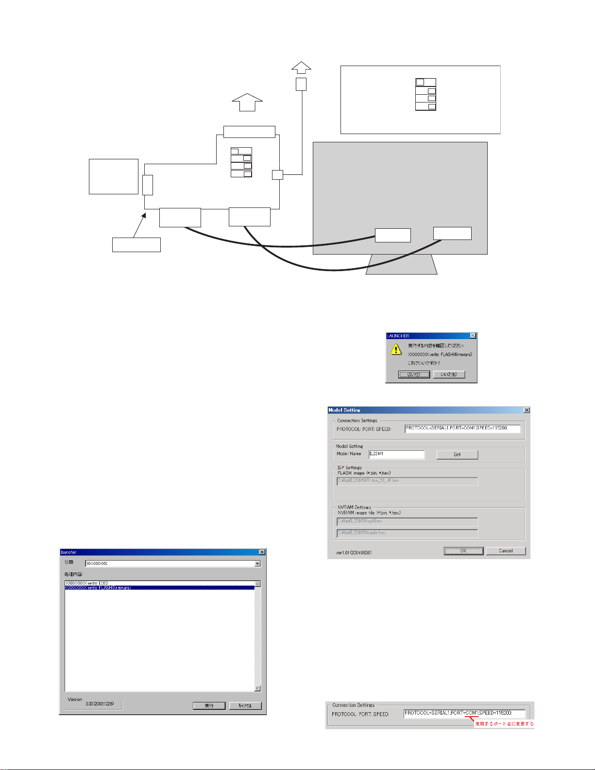
[IT-23M1 EDID writing tool connection diagram]
Connect to
the USB port of PC
No need to
connect a
serial cable.
X1049MP-27
Serial connector
DVI-D
connector
Connect to
the printer port of PC
Parallel connector
Board
VGA
connector
DVI-D cable
USB
2-7. IT-23M1 Flash Writing Procedures
[Tool target models]
IT-23M1
[Tool operating environment]
• Windows 98/ Windows 2000/ Windows XP
[Installing procedures]
(1) Create a folder of "c:\fg."
(2) Copy all the files in the launcher tool into c:\fg folder.
(Use the launcher tool of the latest version.)
(3) Copy all the files in the Flash writing tool FD into c:\fg folder.
(4) Double-click "install.bat" in c:\fg folder. (If the MS-DOS prompt does
not disappear automatically, delete is manually.)
(5) Copy all the files in the Flash writing data FD into c:\fg folder.
[Operating procedures]
(1) Connect the jig to the PC. (Refer to the connection diagram.)
(2) Execute "c:\fg\launcher. exe."
(3) The following window is displayed. Select suitable items in [Classifi-
cation] and [Process content].
Select the target model in [Classification].
Select [XXXXXXXX (Target model) write FLASH (firmware)] in [Pro-
cess content].
DIP switch setting
USB cable
VGA cable
SW1:Parallel(EDID)
SW2: AUTO
SW3: 1502A
SW4: 1502A
Left, Right, Right, Right (from the top with the parallel
connector at the top)
IT-23M1
Back of the Unit
DVI pin
Serial(PROGRAM)
MANUAL
T1620
T1620
VGA pin
The confirmation window for execution is displayed. If it is OK, press
[YES]. If not, press [NO]. When [NO] is p ressed, the proc ess ret urns to
(3). When [YES] is pressed, the process goes to the next step.
When a button is pressed, the window is changed.
(4) The following window is displayed. Connect the jig to the monitor.
After selection, click [EXECUTE].
[Monitor setting]
1. Connect the VGA cable to the jig.
2. While pressing [
[
] (Sound volume/Brightness), turn on the power and wait until
e
] (Tuning) and [d] (Sound volume/Brightness) and
c
[ISP MODE] is displayed. After confirming that [SP MODE] is displayed, press [Decide/Energy Save] key.
[Setting on the writing tool side]
Execute the PORT setting in [Connection Settings]. (The figure shows
the case where COM1 port is sued. When COM4 port is used, write as
"PORT=COM4" on the display below. Once it is set, it is saved.
Change the port name to the actually used port name.
IT-23M1U CONNECTION, ADJUSTMENT, OPERATION, AND FUNCTIONS
2 – 12
Page 18
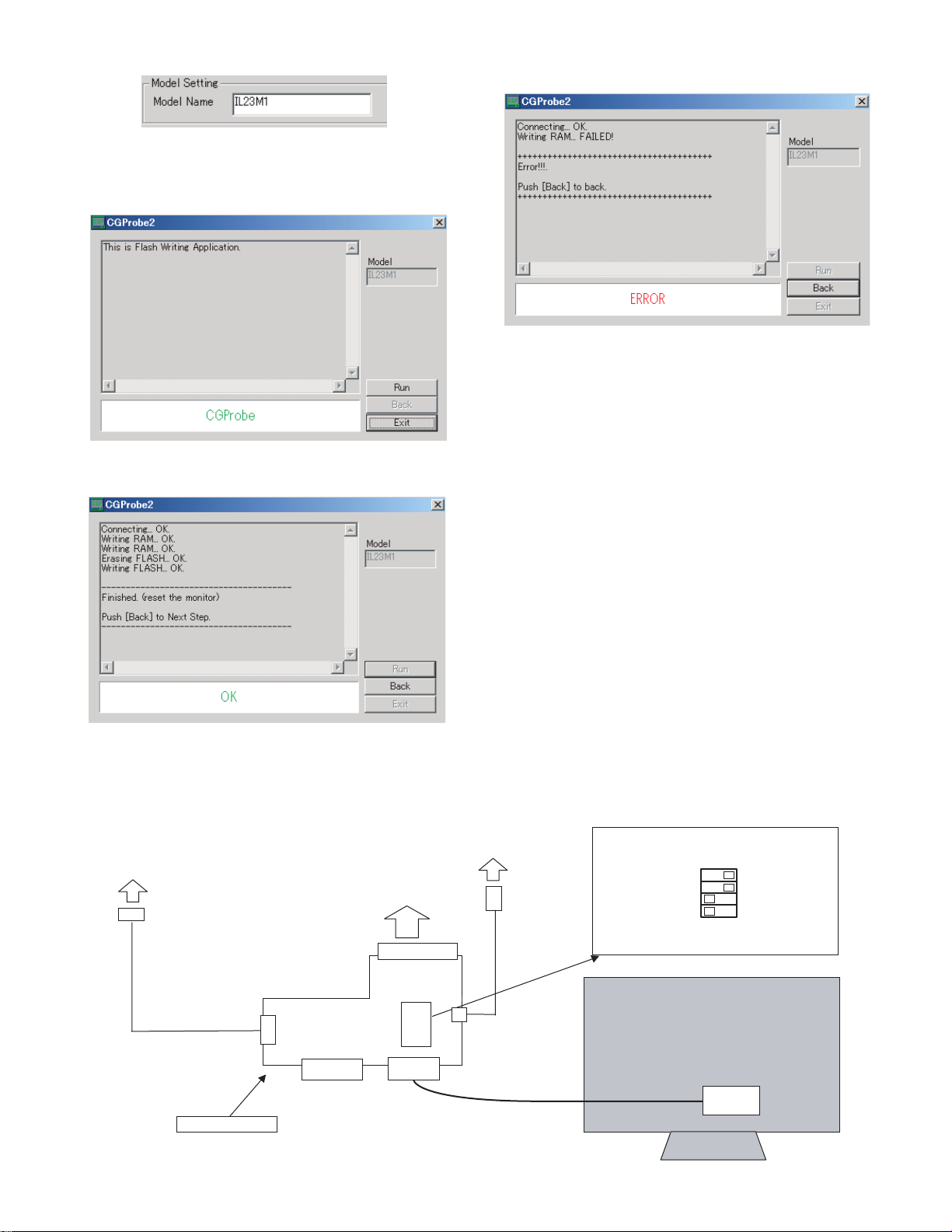
(5) Check the model name .
After checking, press OK button.
(6) The following window is displayed.
When [Run] button is pressed, writing FLASH is executed.
(7) When writing is completed, the following window is displayed. ("Fin-
ished. (reset the monitor)" is displayed.)
(8) When an error occurs in writing, the following window is displayed.
("Error!!!" is displayed.)
(9) After normal completion of writing, disconnect the power cable of
the monitor and connect it again. Press [POWE R] key of the monitor to turn off.
(10)When [Back] button is pressed after normal c ompletion of writing,
the process returns to the window of item (6). From then, writing to
another set can be executed.
While pressing [
[
] (Sound volume/Brightness), turn on the power and wait until
e
] (Tuning) and [d] (Sound volume/Brightness) and
c
[ISP MODE] is displayed. Press [Decide/Energy Save] key and
repeat procedures from (6).
(11)To terminate writing FLASH, press [Back] button and press [Exit]
button.
[IT-23M1 FLASH writing tool connection diagram]
Connected to PC COM1 port
Connected to PC
RS-232C(Dsub9pin)
Cross cable
USE X1049MP-27.
(Not required when writing firmware)
Parallel connector
Serial connector
Board
DVI-D
connector
IT-23M1U CONNECTION, ADJUSTMENT, OPERATION, AND FUNCTIONS
Connected to PC USB port
USB
VGA
connector
2 – 13
USB cable
VGA
cable
X1049MP-27 DIP swch direction
SW1 firmware is on the Serial side.
SW1Parallel(EDID) Serial(PROGRAM)
SW2 AUTO MANUAL
SW3 1502A T1620
SW4 1502A T1620
Right, Right, Left, Left from the top with the parallel
connector at the top
IT-23M1
Back surface
VGA
pin
Page 19
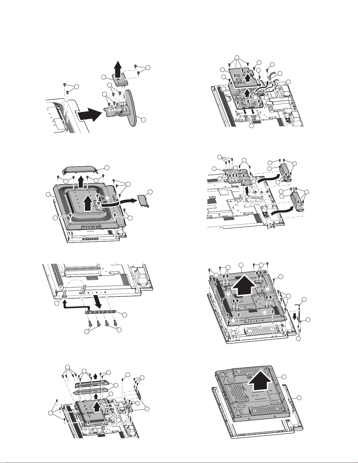
CHAPTER 3. DISASSEMBLY AND ASSEMBLY
1. STAND DISASSEMBLY
1. Remove two screws 1, and remove the stand cover 2.
Remove six screws
, and remove the stand 4.
3
2
3
3
3
4
2. KEY PWB DISASSEMBLY
1. Remove the left rear cover 1 and the lower rear cover 2 .
Remove twelve screws
3
4
and remove the rear cover 4.
3
1
3
3
3
2. Remove five screws
Disconnect the connector
and remove the main PWB
1
, and remove the heat sink 2.
1
at five positions, remove six screws 4,
3
.
5
1
2
4
5
4
1
4
3
4
3
3
4
4. SPEAKER UNIT DISASSEMBLY
1) Remove ele ven screw s 1, and remove the bracket 2.
Remove eight screws
1
2
1
2
, and remove the speaker unit 4.
3
1
1
3
4
1
3
3
4
3
3
3
2. Remove four screws
and remove the key PWB
2
, disconnect the co nnect or 2 at one position,
1
.
3
1
3
3
1
3.MAIN PWB DISASSEMBLY
1) Remove eleve n screws 1, and remove the I/O cover 2.
Remove twelve screws
3
3
, and remove the shield plate 4.
3
1
1
3
2
4
3
1
1
5. SWITCH PWB DISASSEMBLY
1) Remove nin eteen screws 1, and remove the thermal base plate 2.
Disconnect the connector
and remove the switch PWB
1
1
1
at one position, remove two scre ws 4,
3
.
5
2
1
1
1
1
1
1
3
5
4
6. LCD UNIT DISASSEMBLY
1.Remove the LCD unit 2 from the display cover 1.
2
1
2
3
IT-23M1U DISASSEMBLY AND ASSEMB LY
3 – 1
Page 20
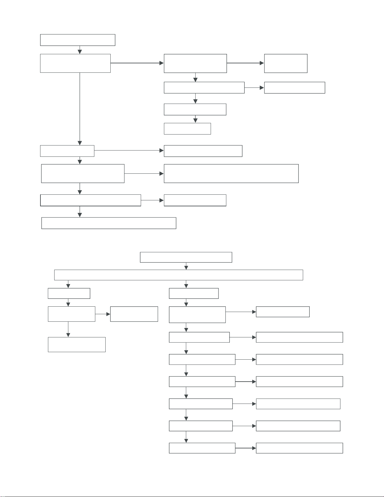
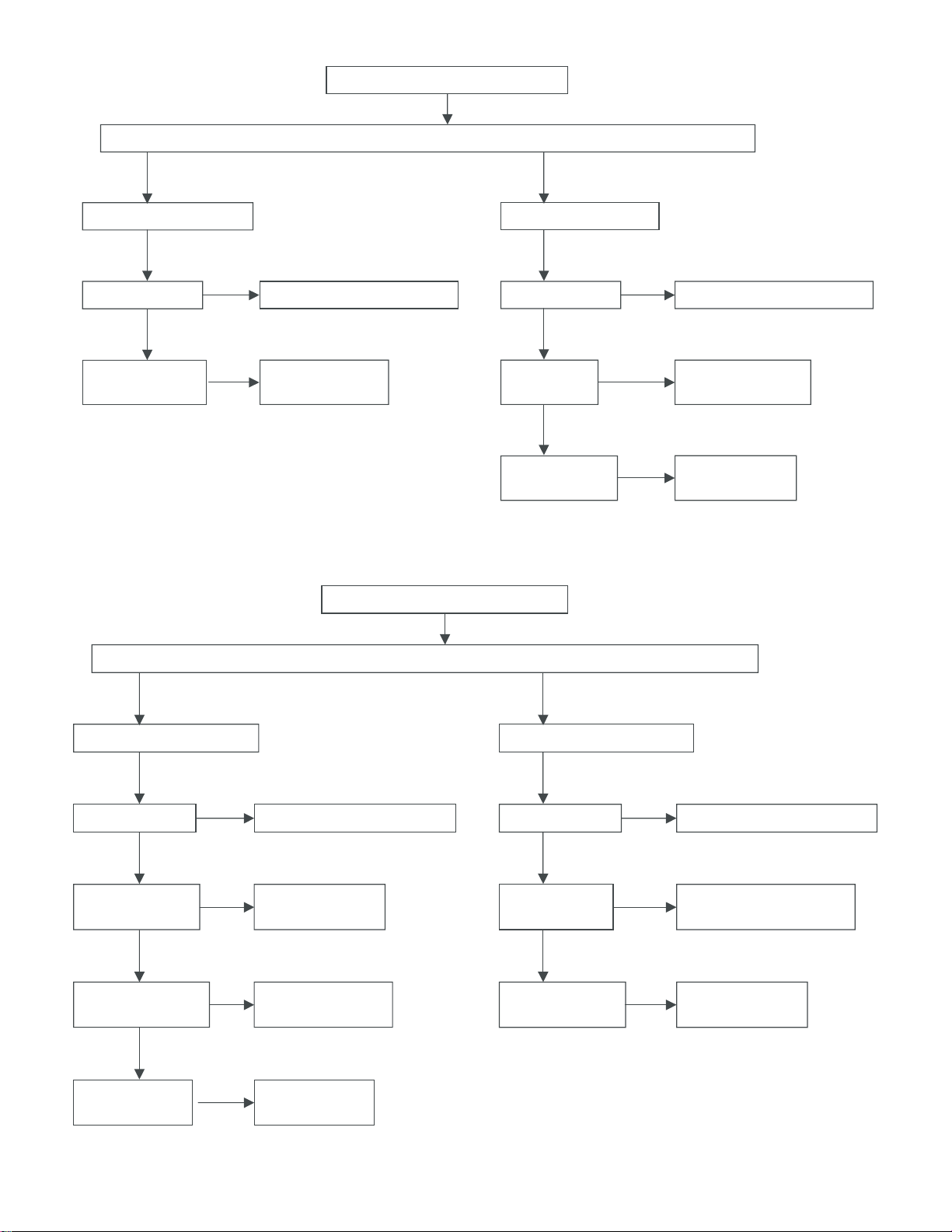
CHAPTER 4. TROUBLE SHOOTING
No image or sound comes out.
Is the power LED lit up
in green?
Yes
Is the backlight off?
Yes
Are the pin(1),(2),(12) of J4
andthe pin(1) of J503 normal?
Yes
Is the main voltage +V_MAIN normal?
Yes
Check the inverter board and connect it properly.
No
No
No
No
Yes
Is the power LED lit
upin orange?
No
Is the power LED lit up in red?
No
Is the AC cord normal?
No
Replace the AC
Proceed to “No picture at all”.
Check U19 and the circuits around it or
performwriting to U26 using the special writing jig?
Check the power line.
Yes
Press any key,
then wake it up
Press the power button
No picture at all.
Is in/output of U19
normal?
Yes
Check LCD panelvoltages
and waveform.
No
There is problems with the picture.(1/3)
Check all the setting microprocessor’s adjust process menu.
Check U19 and the
circuits around it.
TV out is abn
Is voltages at pin(6),(7)
(9) of U33 normal?
Is output of U33 normal?
Is in/output of U15 normal?
Is in/output of U18 normal?
Is in/output of U6 normal?
Is in/output of U4 normal?
Is in/output of U19 normal?
ormal.
Yes
Yes
Yes
Yes
Yes
Yes
No
Check the power line.
No
Check U33 and the circuits around it.
No
Check U15 and the circuits around it.
No
Check U18 and the circuits around it.
No
Check U6 and the circuits around it.
No
Check U4 and the circuits around it.
No
Check U19 and the circuits around it.
IT-23M1U TROUBLE SHOOTING
4 – 1
Page 21
er
Th
problems with the pictur
e is
e.(2/3)
Check all the setting microprocessor’s adjust process menu.
AV1/AV2 ou t is abnormal.
Is TV out normal?
No
Yes
Is in/output of U15
No
normal?
Check U1 5 and the
circuits around it.
There is problems w
Ch
eck a
ll th
e set
ting
ith the
picture.(3/3)
r
ocessor’s adjust process menu.
mic
opr
S-Video out is abnormal.
Is TV ou t normal?
Yes
Is in/outpu
U509 normal
o
f
t
?
Yes
Is in/output of U6
normal?
No
Proceed to “T V out is
Check U5 09 and the
No
c
uits
ci
r
heck U6 and the
C
No
circuits around it
ormal”Proceed to “T V out is abnormal”
abn
a
nd i
ou
t.
r
.
D-co
nnector out is abnorm
I
s TV out nor
mal
Yes
Is in/output of U29
normal?
Yes
Are
in/outpu
ts of U6
and U2 normal?
Yes
Is in/output of U4
normal?
al.
No
?
P
roceed
to
“T
V out
is abnorm
al”
Anal og D-sub o
TV ou t no
Is
ut is
rmal?
abn
ormal.
No
P
roce
ed to “T
is
V
ou
o
t
abn
rmal
”
Yes
Check U2 9 and the
No
ci
rcu
its around it.
Is in/output of J8
normal?
Connect properly and check
No
th
ircuits around it.
e c
Yes
Check U6
No
the circuits around it.
C
No
heck U4 a n
or U2 and
d the
Is in/output of U19
normal?
No
C
heck U1
circuits around it.
9 an
d the
circuits around it.
IT-23M1U TROUBLE SHOOTING
4 – 2
Page 22

There is problems with the sound.
Check all the setting microprocessor’s adjust process menu.
Is the sound from speaker abnormal?
Yes
Is in/output of U32
No
normal?
Yes
Are in/outputs of
No
U504 normal?
Yes
Is in/outputs of U39
No
normal?
Yes
Is in/outputs of U36
No
normal?
Yes
Check the speaker and
connect it properly.
Check U32 and the
circuits around it.
Check U504 and the
circuits around it.
Check U39 and the
circuits around it.
Check U36 and the
circuits around it.
No
Sound from headphone is abnormal.
Is in/output of U34
No
normal?
Yes
Check the headphone and
connect it properly.
Connect U34 and the
circuits around it.
IT-23M1U TROUBLE SHOOTING
4 – 3
Page 23

CHAPTER 5. BLOCK DIAGRAM
I/F PWB
J2
1INPUT
2MENU
3OK
4 CHANNEL_UP
5 CHANNEL_DOWN
6 VOLUME _UP
7VOLUME_DOWN
8GND
J4
1 BRIGHT_ON_OFF
2 BRIGHT_CONTROL
3GND
4GND
5GND
6GND
7GND
8 +24V
9 +24V
10 +24V
11 +24V
12 +24V
J15
1SELECT
2 LED_RED
3HP_VOC
4 LED_GREEN
5 HEADPHONE_R
6GND
7 HEADPHONE_
8 TR_DATA_IN
9 HEADPHONE_L
10 +5V
11 GND
12 BTN_DETECT
J16
1 Speaker_OUT1+
2 Speaker_OUT 13 Speaker_OUT2+
4 Speaker_OUT 2-
J503
1 +24V
2 +24V
3 +24V
4 +24V
5 +24V
6GND
7GND
8GND
9GND
10 GND
J9
1 +12V
2 +12V
3 +12V
4 +12V
5NC
6 PANEL_ID1
7GND
8GND
9TXA010 TXB011 TXA0+
12 TXB0+
13 GND
14 GND
15 TXA116 TXB117 TXA1+
18 TXB1+
19 GND
20 GND
21 TXA222 TXB223 TXA2+
24 TXB2+
25 GND
26 GND
27 TXAC28 TXBC29 TXAC+
30 TXBC+
31 GND
32 GND
33 TXA334 TXB335 TXA3+
36 TXB3+
37 GND
38 GND
39 SELECT
40 GND
KEY PWB
J502
1 INPUT
2MENU
3OK
4 CHANNEL_UP
5 CHANNEL_DOWN
6 VOLUME_UP
7VOLUME_DOWN
8GND
IR PWB
J501
1POWER
2LED_RED
3HP_VOC
4 LED_GREEN
5 HEADPHONE_R
6GND
7 HEADPHONE_
8 TR_DATA_IN
9 HEADPHONE_L
10 +5V
11 GND
12 BTN_DETECT
LL-T17A4-H/B BLOCK DIAGRA M
5 – 1
Page 24

CHAPTER 6. HARDWARE DESCRIPTION
1. CIRCUIT DESCRIPTIONS
1-1. TV TUNER U33 (VT2U5JF561)
The VT2U5JF561 is a TV tuner of NTSC system for use in Japan.
It operates on the power voltage of 5V (6, 7 pins) and the tuning voltage
of 30V (9 pin). 31V is boosted and generated by the double current rectifier circuit of the PU7 peripherals.
Control of tuning is performed y I2C bus (4, 5 pins), and video signals (1
Vp-p) is outputted to 19 pin and inputted to the video switch U15.
The FM signal (about 50mVp-p) of sound SIF is outputted to 15 pin and
supplied to the audio processor U32.
1-2. VIDEO SIGNAL PROCESS
1-2-1. Composite signal input switch U15 (MM1117)
The video signal and the tuner signal inputted to the composite video signal
input pin are inputted to the U15 (3 input 1 output video signal s witch IC ).
The UT9 is controlled by the control pin 1 (2 pin) and the control pin 2 (4
pin) as shown in the table below.
SW1 (2 pin) SW2 (4 pin) OUT (7 pin)
LLIN1
HLIN2
LHIN3
HHMUTE
The output is Y/C separated (separation of the brightness signal and the
color signal) by the 3- dimentional T/C separat ion IC U18 (uPD64084), and
supplied to the video decoder U6 (VPC3230D).
1-2-2. D pin signal process
The component signals (Y/Pb/Pr signals) are received from the component pin (D pin) by the video filter U29 (SM5301AS).
The D1 (480i) signal of the Y/Pb/Pr signals is passed to U6, and the
D2(480p)/D3(1080i /D4(720p) signals are passed through the A/D converter U2 (MST9883C) and converted into digital RG B signals and outputted to the IP conversion U4 (FLI2310).
1-2-3. Video decoder U6 (VPC3230D)
The Y/C input from the tuner, the external input pin, and S pin are Y/C
separated by the U18 (uPD64084) an d the Y/Pb/Pr signals from D pin
(D1 signal) are converted into the digital Y/Pb/Pr signals and outputted
to the IP conversion U4.
1-2-4. IP conversion U4 (FLI2310)
The FLI2310 converts the interlace digital Y/Pb/Pr signals from the
video decoder (U6) into the progressive digital RGB signals, and performs IP conversion of the digital RGB signals from U2.
1-2-5. Scaler & CPU U19 (gm1501)
The gm1501 allows direct input of the analog RGB signal/digital DVI
signal for PC and converts the digital RGB input from U4 into the specified screen size, supplying the VDS signal to the LCD module. It also
provides the functions as a microprocessor and controls many IC's
according to the Flash memory (U26) information.
As additional functions, it also provides the PinP (Picture in Picture)
function of the PC input and the tuner or the external video input, the
frame rate change function, and the OSD (On-Screen Display) function.
1-3 AUDIO SIGNAL PROCESS
1-3-1. Audio processor U32 (MSP3440G)
The MSP3440G decodes the SIF signal input (50 pin) of the tuner output into proper stereo and monaural format, performs sound quality setting by Bass and Treble, performs sound quality setting (fixed) by
various input sources, and other audio signal processes.
Switched to the tuner input (67 pin), the external input signal (57, 58
pins/ 53, 54 pins) and the PC AUDIO input (50, 51 pins).
Outputted from 27/28 pins to the speaker amplifier.
Outputted from 24/25 pins to the headphone amplifier.
1-3-2. Speaker amplifier U36 (LA4636)
The U36 is a BTL-type operation amplifier of 11W. It drives two 8-ohm
speakers of L and R channels. Sound signals inputted from 2/4 pins are
outputted to 8/9 pins and outputted to the L and R channels of the
speaker in reverse polarity. The power is supplied through PU5, and
12V is supplied to 7 pin.
1-3-3. Headphone amplifier U34 (LM4911)
The headphone amplifier is se para tely pro vid ed.
Switch control between the speaker amplifier and the headphone amplifier
is performed by connection an d dis conne ction of the head phone pl ug.
1-3-4. Regulator PU3 (SC1403)
The SC1403 is a step-down, 2-output voltage regulator.
Input voltage : 22 pin (24V)
Output : 26 pin (3.3V system) and 17 pin (5V system)
The output is fed back to 3 pin and 12 pin to provide stabilized voltage.
The feedback voltage to 4 pin is compared wit h the reference voltage
2.5V of the internal operation amplifier to determine the output voltage.
1-4. INVERTER UNIT (KLS-EE32-M/S)
This unit is the EEFL backlight (fluorescent lamp) lighting unit to adjust
the brightness of the LCD panel. It is composed of Master (KLS-EE32M) and Slave (KLS-EE32-S).
Master : 1 - 5 pins : Power source (24V).
6 - 10 pins : GND.
11 pin : Brightness adjustment pin
(0V: min. brightness; 3.3V: max. brightness).
12 pin : ON/OFF control signal (ON for 2V or above).
Slave : 1 - 5 pins : Power source (24V).
6 - 10 pins : GND.
11, 12 pins :The operation of the inverter unit may be
interrupted by the protection circuit when an
error occurs in the NC lamp.
Caution: The inverter unit supplies a high voltage of about 1000V by the
booster transformer to the lamp. Putting your hands closer to
the output connector etc. is very dangerous. Use great care
when repairing.
1-5. AC ADAPTER (NL-A72J)
This is the automatic power source of output 24V, 5A (MAX). It can be
used at AC90 - 264V (50/60Hz). The output plug is composed of two
outputs pins and two earth pins.
The protection circuits for an overvoltage, an overcurrent, and temperature. When the power is shut down, the unit can be reset by disconnection and connection of the AC plug.
Two fuses are provided on the primary side.
1-6. REMOTE CONTROL
When the remote control key is pressed, infra-red rays are radiated in
pulses. (Remote control cord). The light receiving section U35 of the
remote control attached to the front of the machine receives infra-red
rays and converts them into a voltage. The informat ion is pas sed t o th e
microprocessor to perform proper processes.
IT-23M1U HARDWARE DESCRIPTION
6 – 1
Page 25

B
B
B
D
D
D
D
1/27
12345678
12345678
12345678
12345678
C
C
C
C
B
A
Low :POWER OFF-RED(POWER SAVE
ORIGINAL)
Low (POWER ON -GREEN)
OUTPUT(CMOS3.3V)
INPUT/OUTPUT
(D:during/A:after reset)
OUTPUT(CMOS3.3V)
OUTPUT(CMOS3.3V)
BLADJ (BACKLIGH 0 -3.3 V)
LED2_KEYPAD (GREEN )
FUNCTION DEFAULT
LED_KEYPAD (RED)
GPIO_11 (PWM1)
GPIO LIST
GPIO_10 (PWM0)
GPIO_12 (PWM2)
CHAPTER 7. CIRCUIT DIAGRAM & PWB LAYOUT
1. CIRCUIT DIAGRAM
Low : Interlace High : Progressive
To select video source through MM117
To select video source through MM117SV_SEL2
Low -STANDBY(after boot change to High)
Low-MUTE(after boot change to High)
INPUT(D:low/A:low)
OUTPUT(D:low/A:low)
INPUT(D:low/A:low)
SYNCDET
D_I/P
HP_MUTE (L-MUTE)
GPIO_G10_BIT 0(OCM_DATA 8)
GPIO_G10_BIT 02(OCM_DATA 10)
GPIO_G10_BIT 01(OCM_DATA 9)
H-POWER ON /L-POWER OFF
OUTPUT(CMOS3.3V)
OUTPUT(CMOS3.3V)
OUTPUT(CMOS3.3V)
OUTPUT(CMOS3.3V)
OUTPUT(CMOS3.3V)
AMP_STBY (L -STANDBY)
D_CONNECT_SEL
SV_SEL1
POWER_OFF
GPIO_G10_BIT 05(OCM_DATA 13)
GPIO_G10_BIT 04(OCM_DATA 12)
GPIO_G10_BIT 03(OCM_DATA 11)
GPIO_G10_BIT 07(OCM_DATA 15)
GPIO_G10_BIT 06(OCM_DATA 14)
SYSTEM RESUM FROM
POWER
SYSTEM POWER ON
Project name : Triton
PCB version : R0F
Low-VIDEO ID1
Low-VIDEO ID0
INPUT(D:low/A:low)
INPUT(D:low/A:low)
VIDEO_ID1
VIDEO_ID0
GPIO_G05_BIT 3 (DOGRN5 )
GPIO_G05_BIT 0 (DOGRN2 )
POWER SAVE
SAVE/STANDBY
POWER BPTTOM
Program to output pin
PULL LOWGPIO_G09_BIT 0 (DERED0 )
INPUT(D:low/A:low)
INPUT(D:low/A:low)
VGA_CAB(High:cable plug in)
DVI_CAB(High:cable plug in )
GPIO_G09_BIT 1 (DERED1 )
GM1501 RESET
+3.3/+5V
+3.3V_DIG/ 5V_DVD
POWER OFF(GPIO_G10_BIT 7)
Program to output pin
OUTPUT(CMOS3.3V) Low-reset#(after power on change to High)
OUTPUT(CMOS3.3V)
NA
DEV_RESET#(Low :device reset#)
GPIO_G09_BIT 3 (DOGRN1 )
GPIO_G09_BIT 2 (DEDRN0 )
DEV_RESET#(GPIO_G09_BIT 2)
HP_MUTE
L:ACTIVE H:DISABLE
To detect TV channel
Triton Mother board
L:DISABLE H:ACTIVE
SOFTWARE_I2C
SOFTWARE_I2C
High -ID1
OUTPUT(open Drain)
OUTPUT(open Drain)
INPUT(D:low/A:low)
INPUT(D:low/A:low)
SEC_SCL
SEC_SDA
PANEL_ID1
POWER_SAVE
GPIO_G09_BIT 5 (DEBLU1 )
GPIO_G09_BIT 4 (DEBLU0 )
GPIO_G04_BIT 0(DOBLU2 )
GPIO_G04_BIT 1(DOBLU3 )
AMP_STBY (Low -STANDBY)
KEYPAD
KEYPAD
KEYPAD
KEYPAD
KEYPAD
KEYPAD
INPUT(D:low/A:low)
INPUT(D:low/A:low)
INPUT(D:low/A:low)
MENU
INPUT (High :press on bottom)
OK
GPIO_G04_BIT 4(DOBLU6 )
GPIO_G04_BIT 2(DOBLU4 )
GPIO_G04_BIT 3(DOBLU5 )
MTG25
ID1.2/OD1.78/SLD5
MTG24
ID1.2/OD1.78/SLD5
For AMP HEATSINK Only
KEYPAD
INPUT(D:low/A:low)
INPUT(D:low/A:low)
INPUT(D:low/A:low)
INPUT(D:low/A:low)
VOLUME_DOWN
VOLUME_UP
CHANNEL_UP
CHANNEL_DOWN
GPIO_G04_BIT 6(DOBLU8 )
GPIO_G04_BIT 5(DOBLU7 )
GPIO_G07_BIT 0(DERED2 )
GPIO_G04_BIT 7(DOBLU9 )
1
1
AUD_GND AUD_GND
RESERVED
High : POWER ON
High : I2C Low : RS232
For adjust audio delay timing
For adjust audio delay timing
INPUT(D:low/A:low)
INPUT(D:low/A:low)
INPUT(D:low/A:low)
INPUT(D:low/A:low)
INPUT(D:low/A:low)
BTN_DETECT
SW_PWR_OFF
SHP_DEBUG
COUNT0
COUNT1
GPIO_G07_BIT 2(DERED4 )
GPIO_G07_BIT 4(DERED6 )
GPIO_G07_BIT 3(DERED5 )
GPIO_G07_BIT 1(DERED3 )
GPIO_G07_BIT 5(DERED7 )
TVTUNER_GND
PJO502
SHORT-SMT4
1 2
PGND
For detect S2 screen mode
For detect S2 screen mode
Reseved to adjust SM5301 video buffer filter frequency
Reseved to adjust SM5301 video buffer filter frequency
INPUT(D:low/A:low)
INPUT(D:low/A:low)
S2_DETECT2
VFC1
VFC2
S2_DETECT1
GPIO_G07_BIT 7(DERED9 )
GPIO_G06_BIT 0(DORED2)
GPIO_G07_BIT 6(DERED8 )
GPIO_G06_BIT 1(DORED3)
1
FD1
FD_DOT040
1
FD2
FD_DOT040
1
FD4
FD_DOT040
1
FD3
FD_DOT040
VD_GNDPGND
PJO504
PJO501
SHORT-SMT4
1 2
1 2
CLOSE CAPTION_INTERRUPT
L:ACTIVE H:DISABLE
L:PLUG H:UNPLUG
NA (10K Pull-low)
PLUG_DETECT
CC_INT
DEBUG_DETECT
GPIO_06 (VODD_EN)
GPI_10 (OCM_INT1)
GPIO_G06_BIT 3(DORED5)
GPIO_G06_BIT 2(DORED4)
1
FD502
FD_DOT040
1
FD504
FD_DOT040
1
FD503
FD_DOT040
1
FD501
FD_DOT040
GND
PJO503
SHORT-SMT4
SHORT-SMT4
1 2
PGND
L:ACTIVE H:DISABLE
L:ACTIVE H:DISABLE
L:DISABLE H:ACTIVE
L:DISABLE H:ACTIVE
To adjust SM5301 frequency cut point
Program to output pin
L:DISABLE H:ACTIVE
VFC_PWM
LA4635_MUTENAD_MODE_SEL
GPIO_13 OCM_TIMER1 (PWM3)
GPIO_14 (DHS_EN)
I2C_CTL
HOTEL_MODE
EN_BL_PWR
GPIO_15 (DVS_EN)
GPIO_16 (DEN_EN)
GPIO_17 (DCLK_EN)
GPIO_23 (OCM_CS0_EN)
GPIO_24 (OCM_CS1_EN)
1
MTG15
ID3.8/OD8.0
MTG3
ID3.5/OD8
7
6
1
5
2
4
3 8
FOR ESD
AUD_GNDPGND
1
MTG4
ID3.5/OD8.0
MTG12
ID3.5/OD8
7
6
1
5
2
4
3 8
L:IN1 H:IN2
H:HEADPHONE IN
IR_DATA0
NA (10K Pull-low)
SEL_3230_VIN2
GPIO_25 (OCM_CS2_EN)
GPIO_29 (IR1_EN)
GPIO_31 (VCLAMP_EN)
GPIO_30 (OCM_INT2 ) HEADPHONE_DETECT
SHORT-SMT4
JO525
1 2
SHORT-SMT4
JO524
1 2
SHORT-SMT4
JO523
1 2
SHORT-SMT4
JO527
1 2
SHORT-SMT4
JO522
1 2
SHORT-SMT4
JO521
1 2
SHORT-SMT4
JO526
1 2
GNDTVTUNER_GND VD_GND IO_GNDIO_GND VD_GND
MTG23
ID3.8/OD8.0
MTG22
ID3.8/OD8.0-CP
MTG9
ID3.8/OD8.0-CP
MTG8
ID3.8/OD8.0-CP
MTG16
ID3.5/OD8
1
2
MTG14
ID3.8/OD8.0-CP
MTG11
ID3.5/OD8.0
MTG138_RD315A
For ES D
1
TP560
TOUCHPAD_METAL16
1
TP559
TOUCHPAD_METAL16
1
TP558
TOUCHPAD_METAL16
1
1
PGND AUD_GND
1
1
GND GND
7
6
5
4
3 8
1
PGNDPGND
1
GND GND AUD_GND
21
21
21
21
3
3
3
3
Close to D-SUB Close to DVI Close to PC audio in
87654
87654
87654
87654
B
B
B
D
D
D
D
C
C
C
C
B
A A
A A
A A
A
IT-23M1U CIRCUIT DIAGRAM & PWB LAYOUT
7 – 1
Page 26

B
B
B
D
D
D
D
2/27
12345678
12345678
12345678
12345678
C
C
C
C
LLCCDD
PPaanneell
2233""
LLVVDDSS
B
either one
A
21
21
21
21
GGMM11550011
SSYYNNCCDDEETT
BBAA77004466FF
RESERVED
7744LLVVCC224455AA
RESERVED
8
8
8
RR
GG
BB
FFLLII22331100
5
GG,, RR,, BB,,
HHSS,, VVSS
3
3
3
3
Tuner->BA7652->uPD64381A->uPD6483A->VPC3230->FLI2310->1501
RGB-->1501
S-Video->VPC3230->FLI2310->1501
AV1->BA7652->uPD6483A->VPC3230->FLI2310->1501
AV2->BA7652->uPD6483A->VPC3230->FLI2310->1501
Dconn(D1)->SM5301AS->VPC3230->FLI2310->1501
DVI->150 1
Dconn(D2/D3/D4)->SM5301AS->AD9883->FLI2310->1501
VVOOUUTT
VOUT
3
ZZ8866112299
RESERVED FOR US
Triton System Block Diagram
R1/G1/B1
Vin4--> Y
Vin1--> C
RR,,GG,,BB
2
YY,,CC
3D Y/C
uuPPDD6644008844AA
Video Switch
MMMM11111177
CCVVBBSS
SHARP VT2U5JF561 for Japan
SHARP VT2U5UF559 for US
CCVVBBSS
CCVVBBSS
TTVV
AAVV22
AAVV11
TTuunneerr
Vin3--> Y
Cin--> C
2
YY,,CC
VPC3230
ML6428
2
YY,,CC
SS VViiddeeoo
8
Vin2
RESERVED
MM1115
Video Switch
SSOOGG
Cb2/Y2/Cr2
3
D1 480 i
8
RR8BB
YY,, PPbb,, PPrr
D1 480 i
SM5301AS
3
YY,, PPbb,, PPrr
8
8
GG
ADC
5
5W Speaker
5W Speaker
NNJJUU2266110066
Headphone
PROLOGIC II
MMSSTT99888833CC
AUDIO DELAY
RRiigghhtt
II22SS
3
I2S_I N
2
RR,,LL
LLMM44991111
LLeefftt
3
YY,, PPbb,, PPrr
D1 depend on software program
D2 480 p
D3 1080 i
D4 720 p
5
TTMMDDSS
GG,, RR,, BB,, HHSS,, VVSS
LLAA44663366
NNJJUU2266990011
3
II22SS
RRiigghhtt
LLeefftt
I2S_OUT
MMSSPP33444400GG
2
2
RR,,LL
RR,,LL
DD--CCoonnnneeccttoorr
CCRRTT
DDVVII
AAVV11
PPCC
AAVV22
Triton Mother board
D
D
D
D
SSIIFF
87654
87654
87654
87654
C
C
C
C
IT-23M1U CIRCUIT DIAGRAM & PWB LAYOUT
B
B
B
B
A A
A A
A A
A
7 – 2
Page 27

B
B
B
D
D
D
D
3/27
12345678
12345678
12345678
12345678
C
C
C
C
B
A
+3.3V
+3.3V
+3.3V_PLL
+3.3V_PLL
10K/NA
R146
12
C580
12
C593
1
12/12
0603
22P
22P
0603
0603
0603
0603
5.6K/NA
0603
5.6K/NA
0603
R204
5.6K
R205
5.6K
R547
100K
2
+3.3VS_DIG
2
2
0603
0603
0603
(14,17,18)
MSTR_SCL_5
MSTR_SCL_5
DS
D
S
G
(9,11,14,15)
MSTR_SCL
MSTR_SCL
3
4
1A1
1A2
1B1
1B2
U37
256
MSTR_SCL_1601
MSTR_SCL
R546
12
12
D_RESOLUTION
MSTR_SDA_5 (14,17,18)
MSTR_SDA_5
DS
D
S
Q510
2N7002
MSTR_SDA (9,11,14,15)
MSTR_SDAMSTR_SDA_1601
7811
1417182122113
1A3
1A4
1A5
1B3
1B4
1B5
9
101516
MSTR_SDA
TUNER_AFT (18)
TUNER_AFT
150K
0603
C559
0.1U
16V
0603D_1
Q511
2N7002
G
(21)
MSTR_SCL_3D
MSTR_SCL_3D
2A1
2A2
2B1
2B2
C130
1
2A3
2B3
192023
0.1U
2
(21)
MSTR_SDA_3D
12
12
MSTR_SDA_3D
I2C_CTL
2A5
2A4
1OE#
2B4
2B5
VCC
24
V
+5
16V
0603D_1
(18)
TUNER_AGC
GND
TUNER_AGC
15K
R701
0603
R700
5.6K
0603
R180
10K
3D_DEBUG_SEL
1
2OE#
GND
SN74CBTD3384
TSSOP24
12
1U
0603
C190
12
GND
1
+3V_VD
0603
2
GND
P/N = 282074338403
GND
C560
0.1U
16V
0603D_1
2
GND
21
21
21
21
3
3
3
3
87654
87654
87654
87654
J12
123456789
FOR I2C PORT
IR_DATA0 (12)
IR_DATA (12)
MSTR_SDA_1601
MSTR_SCL_1601
1 2
1 2
IR0
R564 33 0603
R567 33 0603
IR1
IR0
MSTR_SCL
MSTR_SDA
RED+
VGA_SCL
SOG
NC_2
C3A1N2
SOG
RED+
(7)
VGA_SCL(7)
(7)
+3.3V
12/12
OCM_RE# (6)
OCM_WE# (6)
OCM_CS# (6)
OCM_CS#
OCM_RE#
OCM_WE#
HEADPHONE_DETECT
R2R1L1
R3
OCM_REn
ROM_CSn
OCM_WEn
VGA_SDA
AHSYNC
AVSYNC
EXTCLK
L4
L3
N1
R4
AVS(7)
AHS(7)
VGA_SDA(7)
10K 0603D_1
1
2
R189
GND
+5V
R240
10K
0603
12
R203
10K
0603
12
CC_INT (17)
R182
10K
0603
1
(12,16)
(20)
SEL_3230_VIN2 (20)
HEADPHONE_DETECT
D_MODE_SEL
OCMADDR[0..18] (6)
OCMADDR19 (6)
OCMADDR[0..18]
I2C_CTL
D_MODE_SEL
SEL_3230_VIN2
OCMADDR19
OCMADDR18
T3
T2
L2P2P1
T4
OCM_INT1
OCM_INT2
OCM_CS2n
OCM_CS1n
OCM_CS0n
OCMADDR19
XTAL
TCLK
NC_4
NC_3
ACS_RSET_HD
F1
K3
K2
G4
G3
C19
XTAL
TCLK
VRED0
ACS_RESET_HD
0603
1%
1 2
R144 3.3K
GND
GND
1
234
A0A1A2
GND
VCC
WP
SCL
SDA
U22
M24C32
SO8
P/N = 283467930005
876
5
GND
0.1U
50V
C175
0603
12
(23)
PWR_RESET#
MSTR_SCL_1601
MSTR_SDA_1601
PWR_RESET#
(11)
R16000603
1 2
0.1U
50V
C161
0603
12
RESET#
R148
0/NA
0603
1 2
12
R147
12
1
2
GND
RESET
VCC
MN
U16
IMP811/NA
4
3
0.01U/NA
C159
12
0603
5%
X3
1 2
0603
5%
2
0.1U/NA
C160
0603
100K/NA
0603
3
SOT14
0.1U/NA
C166
1
0603
14.31818MHZ
50V
GND
0603
AL
XT
GND
GNDGND
50V
2
TCLK
Crystal C-load=20 pF
G_SVDATA[0..7]
G_SVDATA[0..7]
G_SVDATA2
G_SVDATA1
G_SVDATA0
B16
C16
A16
SVDATA0
SVDATA1
U19A
DVI_SCL
DVI_SDA
A8B8A9
N4
N3
DVI_SDA(7)
DVI_SCL(7)
G_SVDATA3
G_SVDATA4
D15
C15
SVDATA2
SVDATA3
RX0+
RX0-
RX0-(7)
RX0+(7)
G_SVDATA6
G_SVDATA5
A15
B15
SVDATA4
SVDATA5
SVDATA6
RX2+
RX1+
RX1-
B9
A10
RX1-(7)
RX1+(7)
RX2+(7)
(11)
G_SVDV
G_SVDATA7
G_SVDV
A17
D14
SVDV
SVDATA7
RXC+
RX2-
RXC-
A6
B6
B10
RX2-(7)
RXC-(7)
RXC+(7)
G_SVODD (11)
G_SVS (11)
G_SVODD
G_SVS
A14
B14
SVODD
SVVSYNC
NC_1
NC_0
C5
D5
(11)
G_SVCLK
G_SHS (11)
G_SHS
G_SVCLK
C14
D16
SVCLK
SVHSYNC
REXT
B11
2
1
R558 249 0603 1%
+3.3V_DVI
RXD
BLUE-
B1
BLUE-(7)
TXD (7 )
RXD (7)
TXD
M1
M2
OCM_UDI
OCM_UDO
BLUE+
GREEN-
B2
C1
BLUE+(7)
GREEN-(7)
RESET#
K1M4M3P4P3
GREEN+
C2
D1
GREEN+(7)
IR_DATA
RESETn
RED-
D2
RED(7)
3D_DEBUG_SEL
DEBUG_SCL_3D(21)
2
OCMADDR16
OCMADDR15
OCMADDR17
U3
T1
U4
OCMADDR18
OCMADDR17
OCMADDR16
OCMADDR15
VRED0
VRED1
VRED2
VRED3
A19
B19
D18
VRED1
VRED2
VRED3
MSTR_SCL_5
MSTR_SDA_5
DEBUG_SDA_3D(21)
VD_GND
OCMADDR14
OCMADDR12
OCMADDR13
U2U1V4
OCMADDR14
OCMADDR13
OCMADDR12
VRED4
VRED5
VRED6
B18
A18
C18
VRED5
VRED4
VRED6
11
10
2
2
1
1
R312 0 0603
R308 0 0603
TXD
DEBUG_DETECT
RXD
DEBUG_DETECT(4)
OCMADDR11
OCMADDR8
OCMADDR9
OCMADDR7
OCMADDR10
V1
W3
V3
V2
W2
OCMADDR9
OCMADDR8
OCMADDR11
OCMADDR10
VRED7
VGRN1
VGRN0
B22
A23
C17
C22
VGRN1
VGRN0
VRED7
VGRN2
VRED[0..7]
VRED[0..7](9)
GND1
GND2
OCMADDR4
OCMADDR5
OCMADDR6
Y3Y2Y1
W1
OCMADDR7
OCMADDR6
OCMADDR5
VGRN2
VGRN4
VGRN3
A22
D21
C21
VGRN4
VGRN5
VGRN3
MA/11PX1/RA
ACES
87213-1100
+3.3VS_DIG
OCMADDR3
OCMADDR2
OCMADDR1
AA3
AA2
OCMADDR2
OCMADDR4
OCMADDR3
OCMADDR1
VGRN6
VGRN5
VGRN7
B21
A21
VGRN6
VGRN7
VGRN[0..7]
VGRN[0..7](9)
P/N = 291000021105
CHANGE P/N
AUD_GND
R556
10K
0603
12
(20)
POWER_OFF (13,24,25)
D_CONNECT_SEL
SV_SEL1 (19)
POWER_OFF
SV_SEL1
D_CONNECT_SEL
SV_SEL2
0603
1 2
1 2
1 2
1 2
R206 100
R207 100 0603
R572 100 0603
R573 100 0603
OCMADDR0
AB1
AC3
AA1
AB3
AB2
OCMADDR0
OCMDATA15
OCMDATA14
OCMDATA13
VBLU1
VBLU2
VBLU0
VBLU3
VBLU4
A25
B25
B24
A24
C24
D24
VBLU2
VBLU4
VBLU1
VBLU5
VBLU0
VBLU3
SYNCDET (18,21)
AMP_STBY (16)
SV_SEL2 (19)
SYNCDET
AMP_STBY
100 0603
2
2
1
1 2
1
R209
R214 100 0603
R211 100 0603
AC2
AC1
AD1
OCMDATA12
OCMDATA11
OCMDATA10
VBLU5
VBLU6
VBLU7
B23
C23
VBLU6
VBLU7
VBLU[0..7]
D_I/P (20)
HP_MUTE (16)
HP_MUTE
0603
1 2
OCMDATA7
R215 100
AE1
AF1
OCMDATA9
OCMDATA8
OCMDATA7
VCLK
VODD
A20
B20
0603
VCLK
1 2
R557 10K
GND
VBLU[0..7](9)
VVS
VCLK(9)
C193
12
OCMDATA4
OCMDATA5
OCMDATA6
AD2
AE2
AF2
OCMDATA6
OCMDATA5
OCMDATA4
VVS
VHS_CSYNC
VDV
C20
D19
D20
VSOG
VHS
VVS(9)
VHS(9)
VSOG(9)
0603D_1
0.1U
16V
OCMDATA2
OCMDATA1
OCMDATA3
AE3
AD3
AF3
OCMDATA3
OCMDATA2
VCLAMP
B17
C26
1 2
R555 10K 0603
GND
1608
EL14
GND
(6)
OCMDATA[0..7]
OCMDATA[0..7]
OCMDATA0
AD4
OCMDATA1
OCMDATA0
PWM1
PWM0
PWM2
C25
D26
D25
LED_KEYPAD
LED2_KEYPAD
VFC_PWM
BLADJ(8)
VFC_PWM(20)
120Z/100M
120Z/100M
2
1608
EL15
1 2
1
LED_RED(12)
LED_GREEN
(12)
LBADC_IN2
OCM_TIMER1
LBADC_IN3
A12
B12
TUNER_AGC
TUNER_AFT
D_RESOLUTION
+5V_VD+5V_VD
+5V_VD
+5V_VD
+3.3VS_DIG
+3.3VS_DIG
+3.3V
LBADC_IN1
LBADC_RETURN
GM1501
D12
C12
R224
15K
12
R235
8.2K
1
R570
10K/NA
1
R542
10K/NA
12
R504
12
R501
1
1/29
12
12
1/29
BGA352_64
P/N = 284501501002
GND
D_DETECT (20)
12
Triton Mother board
D
D
D
D
C
C
C
C
IT-23M1U CIRCUIT DIAGRAM & PWB LAYOUT
7 – 3
B
B
B
B
A A
A A
A A
A
Page 28

B
B
B
D
D
D
D
C
C
C
C
B
A
4/27
12345678
12345678
12345678
12345678
(8)
A1- (8)
A0+ (8)
A2+ (8)TXA0-
A2- (8)
TXA3+ (8)
TX
TXA3- (8)
TXAC- (8)
TXAC+ (8)
TX
TX
TXA1+ (8)
TX
AC
A0+
A3+
TX
TXA0-
TXA2+
TX
TXA2-
TXA3-
TXA1+
TXAC+
TXA1-
TX
(8)
(8)
(8)
(8)
(8)
BC-
BC+
B0-
B3-
B2+
TX
TX
TXB1- (8)
TX
TXB0+ (8)
TX
TXB1+ (8)
TX
TXB3+ (8)
TXB2- (8)
+
BC
B2+
B1+
B3+
TXB1-
TXB0+
TXB0-
TX
TX
TX
TXBC-
TXB3-
TX
TXB2-
+3.3V
EL19
12
EL16
120Z/100M
12
DEBUG_DETECT (3)
EL13
1 2
(20)
PLUG_DET
VFC2
VFC1
PLUG_DET
120Z/100M
1608
1608
220Z/100M
TXAC+
TXA3+
TXA3-
-
TXAC
VIDEO_ID0
VIDEO_ID1
R236
10K
0603
1
R220
10K
0603
1
10K
R219
0603
12
10K*4
RP13
8
7
6
5
A2+
TXA2-
TXA1-
TXA1+
TX
1206
TXA0+
2
2
TXA0-
J2
123
120Z/100M
1608
1 2
1 2
EL506 120Z/100M1608
EL507
INPUTOKMENU
1
2
3
4
POWER_SAVE (23)
PANEL_ID1 (8)
POWER_SAVE
PANEL_ID1
123
2
2
1
1
876
R227 1K 0603
R228 1K 0603
RP12
4
5
120Z/100M1608
120Z/100M
1608
2
1
1 2
1 2
EL510 120Z/100M1608
EL17
EL508
VOLUME_UP
CHANNEL_UP
CHANNEL_DOWN
4
2
1
5
R212 4.7K0603
4.7K*4
1206
678
120Z/100M1608
2
EL18
1 2
1
EL511 120Z/100M1608
VOLUME_DOWN
1 2
1 2
R213 4.7K0603
R66 4.7K0603
GND1
SW_PWR_OFF (22)
GND2
ACES
SHP_DEBUG (7)
COUNT0 (14)
0603
2
0
1
R249
88260-0800
HDR/MA-8
P/N = 291000000028
PGND
+3.3V
(19)
(14)
S2_DETECT1
COUNT1
S2_DETECT2 (19)
0603
1 2
R251 0
Change P/N
R89
10K
0603
R181
2
24
17
TP5
TP521
TP5
TP518
1
1
1
1
B3+
TXB3-
TX
(12)
BTN_DETECT
0/NA
1 2
Q3
1
DS
1
-
+
BC
TX
TXBC
0603
C191
TP519
1
2N7002
D
16
TP5
10K
R577
0603
2
1
R225
10K
0603
+3.3V
SEC_SCL (14)
SEC_SCL
SEC_SDA
2
JTAG_TCK/SCL
JTAG_TDI/SDA
JTAG_TMS
SEC_SDA (14)
TP534
1
DVD_IR
DEV_RESET#
12
12
12
1
(7)
DVI_CAB
DEV_RESET# (9,14,15,17)
VGA_CAB (7)
VGA_CAB
DVI_CAB
10K/NA
10K
R226
0603
R239
10K
0603
R578
10K
0603
2
JTAG_TCK/SCL
JTAG_TMS
JTAG_TDO
JTAG_TRST
JTAG_TDI/SDA
5%
10P
0603
EC16
2
1
GND
0603
R580
1 2
GND
21
21
21
21
3
3
3
3
VFC1
VFC2
+3V_VD
1%
0603 1%
0603 1%
0603
2
21.5K
82.5K
28.7K
1 2
1 2
1
R334
R167
R163
R335
10K
0603
12
0.1U
C140
0603
12
1%
GND
50V
(12,22)
POWER
G
S
GND
R237
5.6K
0.1U
50V
0603
2
GND
1
XB2-
TXB2+
TXB1+
TXB1-
TXB0+
T
0603
12
+3.3V+3.3V
R238
0603
5.6K
1
LA4635_MUTE (16)
EN_BL_PWR (8)
HOTEL_MODE (12)
TP535
TP532
1
1
JTAG_TRST
TXB0-
JTAG_TDO
AC18
AF19
AD18
AE18
AF18
AE19
A3+(DORED6)
GPIO_G06_B0(DORED2)
GPIO_G06_B1(DORED3)
GPIO_G06_B2(DORED4)
GPIO_G06_B3(DORED5)
FSDATA0
FSDATA1
FSDATA2
FSDATA3
FSDATA4
U19B
E26
E24
E25
H26
G26
G24
FSDATAU0
FSDATAU4
FSDATAU3
FSDATAU1
FSDATAU2
FSDATAU5
123
123
4
876
6
5
8
7
RP8
33*4
1206
RP9
33*4
AE20
AF20
A3-(DORED7)
AC-(DORED9)
AC+(DORED8)
FSDATA5
FSDATA6
FSDATA7
FSDATA8
J25
T26
H24
FSDATAU8
FSDATAU6
FSDATAU7
4
876
5
1
RP510
1206
AD21
R25
FSDATAU9
234
33*4
AE21
AE22
AF23
AD22
AF21
AF22
AE23
A1-(DOGRN7)
A2-(DOGRN4)
A0-(DOGRN9)
A2+(DOGRN3)
A1+(DOGRN6)
A0+(DOGRN8)
GPIO_G05_B0(DOGRN2)
GPIO_G05_B3(DOGRN5)
FSDATA9
FSDATA10
FSDATA11
FSDATA12
FSDATA13
FSDATA14
FSDATA15
FSDATA16
FSDATA17
L24
L25
P26
P24
N24
N26
M25
M26
FSDATAU10
FSDATAU16
FSDATAU13
FSDATAU14
FSDATAU12
FSDATAU17
FSDATAU11
FSDATAU15
876
5
123
5
765
1
234
8
RP509
33*4
1206
RP10
33*4
1206
AD24
AF24
GPIO_G04_B0(DOBLU2)
GPIO_G04_B1(DOBLU3)
GPIO_G04_B2(DOBLU4)
GPIO_G04_B3(DOBLU5)
GPIO_G04_B3(DOBLU6)
GPIO_G04_B4(DOBLU7)
GPIO_G04_B6(DOBLU8)
FSDATA18
FSDATA19
FSDATA20
FSDATA21
FSDATA22
FSDATA23
FSDATA24
K24
P25
N23
R26
N25
R24
M24
FSDATAU22
FSDATAU21
FSDATAU18
FSDATAU20
FSDATAU23
FSDATAU24
FSDATAU19
123
4
4
876
8
765
1
1206
RP508
33*4
1206
RP11
AF8
AD9
GPIO_G04_B7(DOBLU9)
GPIO_G07_B0(DERED2)
GPIO_G07_B1(DERED3)
GPIO_G07_B2(DERED4)
GPIO_G07_B3(DERED5)
GPIO_G07_B4(DERED6)
FSDATA25
FSDATA26
FSDATA27
FSDATA28
FSDATA29
FSDATA30
FSDATA31
J26
F24
F25
F26
H25
G23
G25
FSDATAU31
FSDATAU27
FSDATAU29
FSDATAU30
FSDATAU25
FSDATAU28
FSDATAU26
876
5
5
1
234
234
RP507
33*4
33*4
1206
1206
AF10
AD10
AC11
SHIELD[0](DEGRN2)
GPIO_G07_B5(DERED7)
GPIO_G07_B6(DERED8)
GPIO_G07_B7(DERED9)
FSADDR0
FSADDR1
FSADDR2
FSADDR3
AB26
AD25
AC24
AC25
AD26
FSADDRU4
FSADDRU0
FSADDRU2
FSADDRU3
FSADDRU1
876
876
5
123
1
4
RP513
RP514
1206
33*4
AD11
AE11
AF11
AF12
AE12
AF13
B3-(DEGRN7)
BC-(DEGRN9)
B3+(DEGRN6)
BC+(DEGRN8)
SHIELD[1](DEGRN3)
SHIELD[2](DEGRN4)
SHIELD[3](DEGRN5)
FSADDR4
FSADDR5
FSADDR6
FSADDR7
FSADDR8
FSADDR9
FSADDR10
Y24
AA24
AA25
AB25
AA26
AC26
FSADDRU6
FSADDRU7
FSADDRU8
FSADDRU10
FSADDRU9
FSADDRU5
5
876
234
234
1
33*4
1206
RP512
33*4
1206
AD14
AF14
AE13
B2+(DEBLU3)
SHIELD[4](DEBLU2)
SHIELD[5](DEBLU5)
FSADDR11
FSCLKp
FSCLKn
U24
U23
AB24
FSCLKU+
FSCLKU-
FSADDRU11
5
2
1
1 2
R190 10 0603
R195 10 0603
AE14
AF15
AE15
AF16
B2-(DEBLU4)
B1-(DEBLU7)
B1+(DEBLU6)
FSDQS
L26
T25
FSDQSU
FSDQMU0
1 2
1 2
R151 33 0603
R175 33 0603
AE16
AC7
B0+(DEBLU)
B0-(DEBLU9)
FSDQM0
FSDQM1
FSDQM2
T24
U25
U26
FSDQMU1
FSDQMU2
FSDQMU3
2
1 2
1 2
1
R186 33 0603
R522 33 0603
R540 33 0603
AF17
AD16
DHS
DCLK
FSDQM3
FSWE
V26
V25
FSWEU#
FSCASU#
5
3
4
RP15
33*4
AD7
DVS
FSCAS
V24
FSRASU#
2
1206
DEN
FSRAS
AD8
AE6
AF7
AE7
AF6
GPIO_G08_B5(DOBLU1)
GPIO_G08_B4(DOBLU0)
GPIO_G08_B1(DORED1)
GPIO_G08_B3(DOGRN1)
GPIO_G08_B2(DOGRN0)
FSCKE
FSBKSEL0
FSBKSEL1
PPWR
PBIAS
Y25
Y26
A26
B26
W26
FSBKSELU0
PBIAS
FSBKSELU1
0603
1608
120Z/100M
876
2
1 2
1 2
1
1 2
1
EL501
R59 33
R200 33 0603
R63 33 0603
AC5
AF4
AD6
AF5
AE5
AD5
AE4
GPIO_G09_B5(DEBLU1)
GPIO_G09_B1(DERED1)
GPIO_G09_B0(DERED0)
GPIO_G09_B3(DEGRN1)
GPIO_G09_B2(DEGRN0)
GPIO_G08_B0(DORED0)
GPIO_G09__B4(DEBLU0)
NC_5
OEXTR
D_GND_54
GM1501
AC16
AD15
AC17
OEXTR
R571
12
BGA352_64
P/N = 284501501002
GND
3.3K
0603
VFC(20)
R582
10K/NA
0603
R581
10K
0603
2
1
12
12
VIDEO_ID1
GND
R579
10K
0603
GND
R583
10K/NA
0603
12
+3.3V +3.3V
GND
VIDEO_ID0
AD23
AE24
AF25
AF26
AE25
AE26
AE8
AC9
AE9
AF9
AE10
MOTHER BOARD ID
FSDATA1
FSDATA0
FSDATA2
FSDATA[0..31]
FSDATA[0..31](6)
FSDATA3
FSDATA4
FSDATA5
FSDATA6
FSDATA7
FSDATA8
FSDATA9
FSDATA10
FSDATA11
FSDATA13
FSDATA12
FSDATA14
FSDATA15
FSDATA16
FSDATA18
FSDATA17
FSDATA19
FSDATA20
FSDATA21
FSDATA24
FSDATA22
FSDATA23
FSDATA26
FSDATA25
FSDATA27
FSDATA28
FSDATA29
FSDATA30
FSDATA31
FSADDR1
FSADDR3
FSADDR2
FSADDR0
FSADDR[0..10]
FSADDR[0..10](6)
FSADDR5
FSADDR4
FSADDR7
FSADDR6
FSADDR9
FSADDR8
FSADDR10
FSADDR11
FSADDR11(6)
FSCLK+
FSCLK+(6)
FSCLK-
FSCLK-(6)
FSDQS
FSDQS(6)
FSDQM[0..3]
FSDQM[0..3](6)
FSDQM0
FSDQM1
FSDQM2
FSDQM3
FSWE#
FSCAS#
FSWE#(6)
FSCAS#(6)
FSRAS#
FSRAS#(6)
FSBKSEL0
FSCKE FSCKEU
FSCKE
(6)
FSBKSEL1
FSBKSEL0(6)
FSBKSEL1
(6)
ENBL(8)
ENVGA(8)
LCD POWER ENABLE
BACKLIGHT ENABLE
-
PPWR------
PBIAS---
R242
10K
0603
12
+3.3V+3.3V
R241
10K/NA
0603
12
POWER_SAVE
PANEL_ID1
87654
87654
87654
87654
Triton Mother board
B
B
B
D
D
D
D
C
C
C
C
B
A A
A A
A A
A
IT-23M1U CIRCUIT DIAGRAM & PWB LAYOUT
7 – 4
Page 29

B
B
B
D
D
D
D
10U
10V
C618
5/27
+1.8V_CORE
12
C638
12
C623
12
C607
12
C606
12
C608
12
C621
12
C622
12
C609
12
C594
12
C595
12
C630
12
C629
12
C624
12
C626
12
0805
10U
10V
0805
0.1U
16V
0603
0.1U
16V
0603
0.1U
16V
0603
0.1U
16V
0603
0.1U
16V
0603
0.1U
16V
0603
0.1U
16V
0603
0.1U
16V
0603
0.1U
16V
0603
0.1U
16V
0603
0.1U
16V
0603
0.1U
16V
0603
0.1U
16V
0603
GND
+2.5V_DDR
C572
12
C641
12
C584
1
C587
12
C596
12
C603
12
C610
1
C615
12
C619
12
C625
12
C627
12
C633
12
C639
12
16V
0.1U
0603
0.1U
16V
0603
16V
0.1U
0603
2
16V
0.1U
0603
0.1U
16V
0603
16V
0.1U
0603
0.1U
16V
0603
2
0.1U
16V
0603
0.1U
16V
0603
0.1U
16V
0603
0.1U
16V
0603
0.1U
16V
0603
0.1U
16V
0603
GND
+3.3V_I/O_BGA
C631
12
C579
12
C642
1
C640
12
C582
12
C643
12
C644
12
C637
12
C647
12
C636
12
10U
1206
0.1U
0603
0.1U
0603
0.1U
0603
0.1U
0603
0.1U
0603
0.1U
0603
0.1U
0603
0.1U
0603
0.1U
0603
12345678
12345678
12345678
12345678
C
C
C
C
0.1U
16V
C646
0603
1
2
0.1U
16V
C635
0603
+3.3V
+1.8V_ADC
12
C586
12
C620
1
C632
12
C550
1
C581
12
C605
12
C556
12
C557
12
0.1U
16V
0603
0.1U
16V
0603
2
0.1U
16V
0603
0.1U
16V
0603
2
0.1U
16V
0603
0.1U
16V
0603
0.1U
16V
0603
0.1U
16V
0603
0.1U
16V
C574
0603
1
+1.8V_DVI
+3.3V_DVI
C575
1
C577
12
C576
12
C558
1
C562
1
C567
12
C566
1
C565
12
2
0.1U
16V
0603
2
0.1U
16V
0603
0.1U
16V
0603
10U
10V
0805
2
0.1U
16V
0603
2
0.1U
16V
0603
0.1U
16V
0603
2
0.1U
16V
0603
GND GND
10V
16V
16V
2
16V
16V
16V
16V
16V
16V
16V
GND
B
0.1U
16V
C652
0603
1
2
FSVREF
0.1U
16V
C651
0603
GND
+3.3V_LVDSA +3.3V_LVDSB
12
C645
12
C654
12
C653
12
C649
12
C648
12
0.1U
16V
0603
0.1U
16V
0603
0.1U
16V
0603
0.1U
16V
0603
0.1U
16V
0603
GND GND
0.1U
16V
C573
0603
2
1
0.1U
16V
C601
0603
12
0.1U
16V
C583
0603
12
GND
16V
0.1U
C571
0603
12
0.1U
16V
C591
0603
1
2
0.1U
16V
C585
0603
12
0.1U
16V
C602
0603
1
GND
+3.3V_PLL
2
+3.3V_LBADC
+3.3V_LVDS
1
C597
12
C634
12
C578
12
0.1U
C655
A
21
21
21
0.1U
16V
0603
0.1U
16V
0603
GND
0.1U
16V
0603
GND
16V
0603
2
GND
21
3
3
3
3
U19C
+1.8V_CORE
+1.8V_CORE+1.8V_GM1601
L515
1 2
A13
U14
L15
M15
D_GND_0
D_GND_1
D_GND_2
D_GND_3
CORE_1.8_0
CORE_1.8_1
CORE_1.8_2
CORE_1.8_3
L16
K17
U17
U11
BEAD_120Z/100M
0805C_1
P15
R15
U15
D_GND_6
D_GND_4
D_GND_5
CORE_1.8_4
CORE_1.8_5
CORE_1.8_6
L11
T16
T17
M11
N11
R11
D_GND_7
D_GND_8
CORE_1.8_7
CORE_1.8_8
T11
K16
K10
P16
N17
N10
D_GND_9
D_GND_10
D_GND_11
CORE_1.8_9
CORE_1.8_10
CORE_1.8_11
K11
U16
U10
N15
R10
K12
D_GND_12
D_GND_13
D_GND_14
D_GND_15
CORE_1.8_12
VDDA18_DLL
IO_3.3_0
K23
D17
+3.3V_I/O_BGA
+3.3V_I/O_BGA
L516
+3.3V
L12
M13
D_GND_16
D_GND_17
IO_3.3_1
IO_3.3_2
D23
AC4
2
1
M12
AC6
N12
P12
T12
U12
D_GND_18
D_GND_19
D_GND_20
D_GND_21
D_GND_22
IO_3.3_3
IO_3.3_4
IO_3.3_5
IO_3.3_6
IO_3.3_7
D22
AA4W4AB4
AC8
AC10
BEAD_120Z/100M
0805C_1
+3.3V_LBADC
+3.3V
R13
L13
N13
D_GND_23
D_GND_24
IO_3.3_8
IO_3.3_9
Y4
L511
1 2
L10
T13
T10
D_GND_25
D_GND_26
D_GND_27
IO_3.3_10
LBADC_33
C13
H23
+3.3V_LBADC
BEAD_120Z/100M
K14
L14
D_GND_28
D_GND_29
D_GND_30
FS_2.5_0
FS_2.5_1
FS_2.5_2
J23
M23
+2.5V_DDR
0805C_1
P14
N14
D_GND_31
FS_2.5_3
L23
P23
B13
K25
D_GND_32
D_GND_33
VSSA18_DLL
FS_2.5_4
FS_2.5_5
FS_2.5_6
T23
V23
+3.3V_PLL
+3.3V
R23
L512
T14
D_GND_34
FS_2.5_7
FS_2.5_8
Y23
1 2
K15
D_GND_35
FS_2.5_9
AA23
T15
M16
N16
R16
R12
D_GND_36
D_GND_37
D_GND_38
D_GND_39
FS_2.5_10
FS_2.5_11
FS_2.5_12
FS_2.5_13
F23
E23
W23
AB23
AC23
+3.3V_LVDSB
L518
1 2
+3.3V
0805C_1
BEAD_120Z/100M
K13
P13
U13
D_GND_40
D_GND_41
D_GND_42
FS_2.5_14
LVDSB_3.3_0
AC12
AD12
+3.3V_LVDSB
BEAD_120Z/100M
R14
M14
P11
D_GND_43
D_GND_44
D_GND_45
D_GND_46
LVDSB_3.3_1
LVDSB_3.3_2
LVDSA_3.3_0
AD13
AD20
+3.3V_LVDSA
0805C_1
+3.3V_LVDSA
2
L519
1
+3.3V
M17
P17
R17
M10
D_GND_47
D_GND_48
D_GND_49
D_GND_50
LVDSA_3.3_1
LVDSA_3.3_2
VDDD33_LVDS
AE17
AC22
AC21
+3.3V_LVDS
+3.3V_LVDS
L520
+3.3V
0805C_1
BEAD_120Z/100M
P10
L17
D_GND_51
D_GND_52
FSVREF_0
J24
FSVREF
1 2
AC13
AC14
AC15
LVDSB_GND_2
LVDSB_GND_0
LVDSB_GND_1
FSVREF_1
DVI_1.8_0
DVI_1.8_1
D6D8D9
W25
+1.8V_DVI
BEAD_120Z/100M
0805C_1
+1.8V_DVI+1.8V_GM1601
L513
AC20
AC19
LVDSA_GND_0
LVDSA_GND_1
DVI_1.8_2
DVI_1.8_3
D10
2
1
AD19
AD17
K26
VSSD33_LVDS
FSVREFVSS_0
LVDSA_GND_2
DVI_3.3_0
DVI_3.3_1
DVI_3.3_2
DVI_3.3_3
DVI_3.3_4
C8
C6
C9
C11
C10
+3.3V_DVI
+3.3V_DVI
L508
1 2
+3.3V
BEAD_120Z/100M
0805C_1
W24B4D4
E2
ADC_AGND_0
ADC_AGND_1
FSVREFVSS_1
ADC_1.8_0
ADC_1.8_1
A3
A4A2B3D3E3
+1.8V_ADC
0805C_1
BEAD_120Z/100M
ADC_AGND_3
ADC_AGND_4
ADC_AGND_2
ADC_DGND_0
ADC_3.3_0
ADC_3.3_1
ADC_3.3_2
ADC_3.3_3
+3.3V_ADC
2
L509
1
+1.8V_GM1601 +1.8V_ADC
A5E1C4E4A7
B7C7D7
DVI_GND_0
ADC_DGND_1
VDDA33_RPLL
VDDD33_PLL
F4
F2
G1
+3.3V_PLL
0805C_1
BEAD_120Z/100M
D11
A11
DVI_GND_2
DVI_GND_3
DVI_GND_4
DVI_GND_5
DVI_GND_1
VDDA33_FPLL
VDDA33_SDDS_0
VDDD33_SDDS_0
VDDA33_DDDS_1
VDDD33_DDDS_1
J3
J1
H1
H3
+3.3V_ADC
B5
D13F3G2H4H2J4J2
DVI_GND_6
LBADC_GND
0.1U
C561
1
0.1U
C564
12
0.1U
C568
12
0.1U
C569
12
V
+5
VSSD33_PLL
VSSA33_FPLL
VSSA33_RPLL
VSSA33_SDDS_0
16V
0603
2
16V
0603
16V
0603
16V
0603
K4
VSSD33_SDDS_0
VSSA33_DDDS_1
VSSD33_DDDS_1
GM1501BGA352_64
+3.3V_ADC
GND
0.5A/32V
F4
1
GND
P/N = 284501501002
D4
0805C_1
L20
1 2
BEAD_120Z/100M
C120
12
C104
12
GND
VIN VOUT
U10
2 3
12
1
2
L22
1
BEAD_120Z/100M
2
BZT52C4V3
SOD123
A K
0.1U
50V
0603
%
2.2U
0805
+80-20
1
GND
SOT89N
AME8800AEFT
1U
0603
C114
50V
0.1U
C123
0603
2
0805C_1
87654
87654
87654
87654
Triton Mother board
B
B
B
D
D
D
D
C
C
C
C
B
IT-23M1U CIRCUIT DIAGRAM & PWB LAYOUT
7 – 5
A A
A A
A A
A
Page 30

B
B
B
B
+3.3V+3.3V
+3.3V
+3.3V
R173
10K
12
R170
10K
12
R156
10K
12
R140
10K
12
0603
0603
0603
0603
R176
1
OCMADDR15
R171
12
OCMADDR14
R165
1
OCMADDR13
R143
1
10K/NA
10K/NA
10K/NA
10K/NA
0603
2
GND
0603
GND
0603
2
GND
0603
2
GND
08 : LOW (Enable checking external rom),HIGH(Disable checking external rom)
+2.5V_DDR
153565
VDD0
BA1
FSBKSEL1(4)
164666
VDD1
VSS0
2
81422
96
VDD3
VDD2
VDDQ1
VDDQ0
VDDQ2
VSS1
VSS2
VSS3
VSSQ0
VSSQ1
85511196270768292
C
C
C
C
59
VDDQ3
VSSQ2
GND
67
VDDQ4
VSSQ3
73
VDDQ5
VSSQ4
79
VDDQ6
VSSQ5
86
VDDQ7
VSSQ6
VDDQ8
VSSQ7
95
99
VDDQ9
VSSQ8
4344878889
NC6
NC7
NC1
NC0
37
3839404142
2
1
R608 0 0603D_1
NC8
NC2
NC9
NC10
NC3
NC4
90
NC11
K4D263238F-QC50
PQFP100F_EIAJ_1
NC5
P/N = 283767930003
D
D
D
D
6/27
12345678
12345678
12345678
12345678
(4)
FSDATA[0..31]
FSDATA[0..31]
FSDATA27
FSDATA9
FSDATA10
DQ9
FSADDR9
FSADDR10
FSDATA12
FSDATA11
FSDATA13
DQ10
DQ11
DQ12
DM0
235624
FSDQM0
FSDQM1
FSDQM[0..3]
FSDATA18
FSDATA20
FSDATA19
FSDATA21
FSDATA15
FSDATA16
FSDATA17
FSDATA14
697172910121317182021
DQ13
DQ14
DQ15
DQ16
DQ17
DQ18
DQ19
DQ20
DQ21
CAS
DM1
DM2
DM3
CK
CK
WE
25262728525358
57
54
55
FSCAS#
FSDQM3
FSCLK-
FSCLK+
FSWE#
FSDQM2
FSWE#(4)
FSCAS#(4)
FSDATA22
FSDATA24
FSDATA23
DQ22
DQ23
RASCSNC/MCL
FSRAS#
FSRAS#(4)
FSDATA25
FSDATA26
FSDATA28
74757778808183
DQ24
DQ25
DQ26
DQ27
DQ28
CKE
VREF
NC/RFU
DNU
93
91
FSCKE
FSCKE
(4)
FSDATA29
FSDATA30
FSDATA31
DQ29
DQ30
DQS
94
FSDQS
FSBKSEL0
FSDQS(4)
84
DQ31
BA0
29
30
FSBKSEL1
FSBKSEL0(4)
FSDATA0
FSDATA2
FSDATA5
FSDATA4
FSDATA3
FSDATA1
9798100134676061636468
DQ0
DQ1
DQ2
DQ3
DQ4
DQ5
U17
A0A1A2A3A4A5A6A7A8/APA9A10
3132333447484950514536
FSADDR5
FSADDR4
FSADDR2
FSADDR1
FSADDR0
FSADDR3
FSADDR[0..10]
FSDATA7
FSDATA6
FSDATA8
DQ6
DQ7
FSADDR7
FSADDR6
FSADDR8
DQ8
A
output to "0")
H
W
W
10 : LOW (USE TCLK)
11 : LOW (set all display
09 : LOW (DDC2BI ON DVI),HIGH (DDC2BI ON VGA)
12 : LO W
17 : LOW (8 bit bus with OCM access external ROM)
15 : LO
14 : LO
16 : HIGH (use crystal)
18 : HIG
13 : LOW (disable serial interface debug)
21
21
21
21
3
3
3
3
19 : LO W
+2.5V_DDR
1
12
12
12
12
12
12
C604
C217
C612
C589
C84
C109
C617
FSADDR[0..10]
(4)
16V
0603D_1
0.1U
2
0.1U
16V
0603D_1
0.1U
16V
0603D_1
0603D_1
0.1U
16V
0.1U
16V
0603D_1
0.1U
16V
0603D_1
0.1U
16V
0603D_1
12
12
12
12
12
FSDQM[0..3]
(4)
C137
0.1U
16V
0603D_1
C138
0.1U
16V
0603D_1
C590
0.1U
16V
0603D_1
C616
0.1U
16V
0603D_1
C588
0.1U
16V
0603D_1
FSVREF
0.1U
16V
0603D_1
C628
1
2
GND
GND
FSVREF(5)
FSCLK+
FSCLK-
1%
0603D_1
R541
140
12
FSCLK-(4)
FSCLK+(4)
GND
+2.5V_DDR
1
C177
12
FSADDR11
FSADDR11(4)
FSVREF
FSVREF
R194
0603D_1
2
1
C183
12
0603D_1
10K
2
0.1U
16V
0603D_1
R198
10K
0.1U
16V
0603D_1
OCMADDR[0..18] (3)
OCMADDR[0..18]
OCMADDR0
OCMADDR8
OCMADDR6
OCMADDR7
OCMADDR4
OCMADDR1
OCMADDR9
OCMADDR5
OCMADDR11
OCMADDR12
OCMADDR10
OCMADDR3
OCMADDR2
12
11109
8
2726232542829
765
A0A1A2A3A4A5A6A7A8
A9
A10
A11
U26
O0O1O2O3O4O5O6
13141517181920
OCMDATA1
OCMDATA0
OCMDATA[0..7]
GND
OCMDATA[0..7](3)
OCMDATA3
OCMDATA4
OCMDATA2
O7
21
OCMDATA7
OCMDATA6
OCMDATA5
VPP
OCMADDR18
OCMADDR14
OCMADDR15
OCMADDR13
3
A12
A13
A14
OCMADDR16
OCM_CS#
OCMADDR17
22224131
30
A15
A16
A17
VCC
32
+3.3V
OCM_RE# (3)
OCM_CS# (3)
OCM_RE#
CE#
OE#
C237
12
OCMADDR9
OCM_WE# (3)
OCM_WE#
WE#
VSS
16
0.1U
16V
0603D_1
32P/PLCC/SMT
PLCC32
GND
GND
GND
10K*4
1206
RP16
4
5
3
6
2
7
1
+3.3V
+3.3V
8
RP14
10K*4
1206
GND
5
876
123
4
OCMADDR16
OCMADDR10
OCMADDR19
OCMADDR11
OCMADDR18
OCMADDR19(3)
0603
1 2
R177 10K
OCMADDR12
OCMADDR17
GND
0603
2
10K
1
R179
OCMADDR8
87654
87654
87654
87654
Triton Mother board
B
B
B
D
D
D
D
C
C
C
C
B
IT-23M1U CIRCUIT DIAGRAM & PWB LAYOUT
7 – 6
A A
A A
A A
A
Page 31

B
B
B
B
GND
DVI_CAB (4)
0603D_1
DVISCL1
DVISDA1
0603
47
2
1
R267 47 0603
R266
DVISDA
DVISCL
DDC CLK
2
1
NC
DDC DATA
+VGA_5V
RX1IN-
91011
RX1- (3)
RX1IN+
D1-
(3)
RX1+
D1+
100K
1 2
R290 0/NA 0603
R269
0603D_1
1
2
R268 10K
12131415161718
D3-
+5V
D3+
D1/3
GND
U38
0.1U
16V
0603D_1
C192
12
1 2
(3)
(3)
RX2-
RX2+
12/12
D22
BAV99W
3
D23
BAV99W
3
D30
BAV99W
3
D31
BAV99W
3
D24
BAV99W
3
RX2IN+
RX2IN-
D25
BAV99W
3
1
2345678
D2-
D4-
D2+
D4+
D2/4
J10
0.1U
0603D_1
16V
2
GND
10K
0603
2
GND
(3)
RX0- (3)
RX0+
RX0IN-
RX0IN+
21
19
20
D0-
D5-
D0+
D0/5
PLUG
GND1
GND2
GND1
GND2
(3)
RXD
33
0603D_1
1 2
VGA_SDA_DEBUG
R185
1234567
2Y1
2Y0
3Y1
3Y0
3-COM
1-COM
1Y1
1Y0AB
2-COM
VCC
15
141312
11
16
GND
VGA_SCL_DEBUG
1 2
R187 33 0603D_1
D
TX
(3)
222324
D5+
INH
10
(3)
RXC-
RXC+ (3)
RXCIN-
RXCIN+
TMDS CLK
TMDS CLK-
TMDS CLK+
GND
8
GND_0
GND_1
C
9
+5V
FM/3PX8
WIESON
GND
16
SN74LV4053A
TSSOP
D29
BAV99W
3
D28
BAV99W
3
D27
BAV99W
3
D26
BAV99W
3
D17
1
2
3281-380108
P/N = 331000024006
V
12
+5
2
+3.3V
SN74LVC14A
SOIC14
SN74LVC14A
P/N = 282007414004
SOIC14
1 2
R178 33 0603D_1
1 2
L37 BEAD_130Z/100M 0603D_1
02/11
+3.3V
+3.3V
100/NA 0603D_1
1 2
R592
C
C
C
C
GND
GND
2
1
R589 100/NA 0603D_1
AHS
1 2
U20D
147
9 8
6
U20C
147
5
+VGA_5V
3
3
3
3
AHS (3)
R306
33
0603D_1
SN74LVC14A
SN74LVC14A
12/12
D39
BAV99W
D38
BAV99W
D517
BAV99W
D516
BAV99W
SOIC14
SOIC14
12/12
R270
1
1
12
R59000603
2
1
2
1
2
1
GNDGND +VGA_5V GND+VGA_5V +VGA_5V GND +VGA_5V
2
1
10K
R272
GND
GND
0603D_1
10K
VGA_SDA (3)
0603D_1
1 2
R273 33
2
0603D_1
VGA_SDA_DEBUG
2
5
SDA
NC1
U31
123
GNDGND
+DVI_5V
GND
+DVI_5V
+DVI_5V
+DVI_5V
+DVI_5V
GND GND GND
(3)
+DVI_5V
VGA_SCL
0603D_1
2
1
R271 33
VGA_SCL_DEBUG
678
VCC
SCLK
VCLK
NC2
NC3
GND
4
R184
12
R183
1
1
2
1
2
1
2
1
2
1
2
1
2
1
1
ST24LC21B
SO8_1
33
0603D_1
0603D_1
33
C247
R591
2
D
D
D
D
7/27
12345678
12345678
12345678
12345678
(3)
(3)
(3)
(3)
(4)
VGA_CAB
R222
1 2
+VGA_5V
SOG (3)
1 2
C156 0.01U 0603D_1
1 2
R157 470 0603
R221
100K
1
10K/NA
3
RED+ (3)
0603D_1
0.01U
1 2
C158
1%0603D_1
20
2
1
R159
REDU+
GND
+VGA_5V
GND
+VGA_5V
GND
+VGA_5V
0603D_1
0603D_1
D19
RED- (3)
0.01U 0603D_1
2
1
C157
BAV70LT1
GREEN+
0603D_1
0.01U
2
1
C153
0603D_1
1 2
R154 20 1%
GREENU+
D12
1
2
D13
1
2
D14
1
2
2
2
1
BLUE+
GREEN-
0603D_1
0603D_1
0.01U
2
1
1 2
C154
C151 0.01U
1%0603D_1
20
1 2
R152
BLUEU+
BAV99W
3
BAV99W
3
BAV99W
3
GND
BEAD_120Z/100M
L39
12
+5V
BLUE-
0.01U 0603D_1
1 2
C152
0805C_1
0 ohm
J8
0 ohm
0603D_1
16
1/29
1%
R153
57.6
0603
12
1%
R155
0603
57.6
12
1%
R158
57.6
0603
12
GREENU+
REDU+
0 ohm
BEAD_600Z/100M
0603D_1
2
EL10
BEAD_600Z/100M
0603D_1
1
2
EL11
BEAD_600Z/100M
1
6172839410
111213
A-SDA
EL9
BLUEU+
2
1
A-HS
14
A-VS
GND
12
12
12
12
12
12
5
15
17
A-SCL
+3.3V
+3.3V
10P/NA
EC21
R261750603D_1
10P/NA
EC22
R262750603D_1
10P/NA
EC23
R263
75
5%
0603
5%
0603
5%
0603
0603D_1
GND
15P/3R-FM
DAR-15SH-X-X-XXX
P/N = 331000015016
GND
AVS (3)
AVS
33
0603D_1
R299
1 2
U20B
147
3 4
U20A
147
1 2
0603D_1
33
1 2
R188
BEAD_130Z/100M 0603D_1
1 2
L38
GND
T1
BAV70L
+DVI_5V
GND
R139
10K
2
+DVI_5V
1
2
1
GND GND
2
+DVI_5V +DVI_5V
1
2
+DVI_5V
1
GND GND
12/12
10K
R259
12
10K
R260
12
3
INPUTS
FUNTION TABLE
0603
3
Q32
1
A
(3)
(3)
DVI_SDA
DVI_SCL
DVI_SDA
DVI_SCL
1 2
1 2
R246 0 0603
R247 0 0603
DVISCL1
DVISDA1
0603D_1
0603D_1
5
6
SDA
SCLK
U30
A0
A1A2GND
1
234
nY0----nZ
CHANNEL ON
L
Sn
L
ENABLE#
DTC144WK
SOT23AN_1
7
8
WC-
nY1----nZ
H
L
12
VCC
C240
M24C02
SO8_1
NONE
X
H
21
21
21
21
0603D_1
0.1U
16V
3
3
3
3
GND GND
P/N = 283467540001
GND
87654
87654
87654
SHP_DEBUG
(4)
87654
Triton Mother board
B
B
B
D
D
D
D
C
C
C
C
B
IT-23M1U CIRCUIT DIAGRAM & PWB LAYOUT
7 – 7
A A
A A
A A
A
Page 32

B
B
B
D
D
D
D
8/27
12345678
12345678
12345678
12345678
1
6
7
234
5
1
2345678
8910
9
10
HDR/MA/10PX1
JST
S10B-PH-SM3-TB
P/N = 291000001011
PGND
J503
C
C
C
C
B
(4)
(4)
(4)
(4)
BC-
B3+
TX
TXB2+ (4)
TXBC+
TX
TXB2-
TXB3- ( 4)
XB2-
XB3-
T
T
TXB2+
TXBC-
TXBC+TX
TXB3+
22
242628
30
32
343638
40
A
(4)
B0-
B1+ ( 4)
TXB1- ( 4)
TX
TXB0+ (4)
TX
PANEL_ID1 (4)
21
21
21
21
B1+
TXB1-
TXB0-
TXB0+
PANEL_ID1
246810
1214161820
L28
120Z/100M
1 2
876451
3
F8
2
2012
120Z/100M
1
D
G
S
2
12
1 2
6.5A/32VDC
+V_MAIN
C162
100U
+
1
0.1U
C169
12
L27
2012
Q37
R250
220K
6.5A
50V
2
PGND
50V
0603
PGND
AO4407
SO8
12
0603
05/17/2004
BRIGHT
+5V
+5V
J4
9
8
101112
ET
2N7002
R265
220K
0603
Q38
SOT23_F
D
S
D
G
330
1 2
ENABLE BACKLIGHT POWER
EN_BL_PWR
(4)
T3904L
Q17
MMB
B
R113
1 2
1%
R861K0603
12
R3
10K
0603
1
+3.3V
HDR/MA/12PX1
JST
1234567
1608
120Z/100M
S
PGND
1 2
1 2
L24
L25 120Z/100M 1608
R279
0603
C129
1
R126
E C
12
C126
2.2U
0805
X5R
12
200K
0603
1%
T3904L
Q10
MMB
E C
B
2
R87
4.7K
0603
1
2
123
456
7891011
12
S12B-PH-SM3-TB
P/N = 291000001244
+5V
+5V
1U
10V
0805
2
3K
1%
0603
PGND
PGND
PGND
R1251K0603
12
R84
12
PGND
J9
10U
C250
25V
1206
1
2
GND
50V
0.1U
C249
0603
2
1
GND
Q25
AO4407
SO8
L46
876451
F9
3A/24VDC
2
120Z/100M
2012
1
D
G
S
3
2
1%
R253
100K
0603
1
2
1 2
+3.3V
R166
12
MMBT3904L
Q16
E C
10K
0603
Q9
MMBT3904L
E C
B
R85
10K
1 2
ENBL
(4)
BACKLIGHT ENABLE
PGND
PGND
0603
B
R112
1 2
10K
0603
GND1
GND2
10K/NA
0603
C235
12
1
+5V
39
50V
0.01U/NA
0603
R254
33K
333537
A3+
TXA3-
TX
TXA3-(4)
TXA3+(4)
R169
1
10%
0603
2
R264
12
31
10K
47K/NA
-
+
AC
TX
TXAC
TXAC+(4)
0603
GND
DS
0603
PBIAS----
2
2
JO11
OPEN-SMT4
JO10
1 2
SHORT-SMT4
1
JO12
1
OPEN-SMT4
17
19
2123252729
A1+
TXA1-
TXA2-
TX
TXA2+
A1+
TXA1-(4)
TXA2-(4)
TXAC-(4)
TX
TXA2+
(4)
(4)
2
GND
Q24
2N7002
SOT23_FET
D
S
G
R71
1M/NA
0603
12
0.1U/NA
C231
0603
12
2
LCD POWER ENABLE
1
R76 0 0603
111315
TXA0+
50V
MA/20PX2/ST
ACES
87216-4000P/N = 291000144004
3
579
1
A0TX
XA0T
TXA0+(4)
(4)
If pin39 is ground, interface format is “LG”,
GND
3
3
3
3
GND GND
and if pin39 is 3.3V, interface format is
“DISM.
ENVGA------
+5V
+12V
+3.3V
ENVGA
(4)
87654
87654
87654
BLADJ(3)
87654
Triton Mother board
B
B
B
D
D
D
D
C
C
C
C
B
IT-23M1U CIRCUIT DIAGRAM & PWB LAYOUT
7 – 8
A A
A A
A A
A
Page 33

B
B
B
22 0603
R518
1 2
2
1
189
0603
1 2
R520 22
188
TEST1
TEST0
B
Crystal Cload=20P
27P
0603
5%
C48
2
1
X1
13.5MHZ
1 2
27P
0603
5%
C60
2
1
GND
GND
GND
VBLU0
VBLU2
VBLU3
VBLU1
10
131415
11
12
7
132
130
127
131
B/U/Pb_OUT_3
B/U/Pb_OUT_2
B/U/Pb_OUT_4
B/U/Pb_OUT_1
C
C
C
C
VSOG
22 0603
22 0603
8 9
1 2
1 2
R539
R96
R538 22 0603
126
122
121
CTLOUT4
CTLOUT3
B/U/Pb_OUT_0
(3)
VVS (3)
VSOG
VHS
VVS
22 0603
1 2
1 2
R95 22 0603
R94
120
119
CTLOUT2
CTLOUT1
(3)
VHS
1 2
118
CTLOUT0
VCLK (3)
VCLK
22 0603
1 2
R97
125
CLKOUT
0603
22
2
509
TP
TP510
1
1
1
R537
117
116
1154546
TEST OUT1
TEST OUT0
GND
TEST3
MSTR_SCL (3,11,14,15)
MSTR_SDA (3,11,14,15)
MSTR_SDA
MSTR_SCL
0603
33 0603
2
2
1
1
R511
R512 33
SCLK
SDATA
191
192
XTAL IN
XTAL OUT
R551M0603
22 0603
2
1
R519
190
TEST2
D
D
D
D
9/27
12345678
12345678
12345678
12345678
VRED3
VRED4
VRED5
VRED6
12
13
4
567
33*8
RPX8
144
142
141
143
R/V/Pr_OUT_6
R/V/Pr_OUT_5
R/V/Pr_OUT_4
R/V/Pr_OUT_7
VBLU[0..7] (3)
VBLU[0..7]
VRED2
VRED0
VRED1
141516
123
140
137
136
R/V/Pr_OUT_3
R/V/Pr_OUT_1
R/V/Pr_OUT_2
R/V/Pr_OUT_0
VBLU7
VBLU5
VBLU4
VBLU6
16
1
23456
8
RP5
33*8
RPX
134
133
135
B/U/Pb_OUT_7
B/U/Pb_OUT_6
B/U/Pb_OUT_5
VGRN[0..7] (3)
VGRN[0..7]
VGRN7
8 9
RP506
155
VGRN5
VGRN4
VGRN6
VGRN3
10
1112131415
4
567
RPX8
33*8
154
153
151
152
G/Y/Y_OUT_7
G/Y/Y_OUT_6
G/Y/Y_OUT_5
G/Y/Y_OUT_4
G/Y/Y_OUT_3
VRED[0..7] (3)
VRED[0..7]
VGRN2
VGRN0
VGRN1
16
123
150
149
148
G/Y/Y_OUT_2
G/Y/Y_OUT_1
G/Y/Y_OUT_0
VRED7
91011
8
RP505
145
A
21
21
21
21
3
3
3
3
R/Cr/Cb Cr_0
R/Cr/Cb Cr_1
R/Cr/Cb Cr_4
R/Cr/Cb Cr_5
R/Cr/Cb Cr_6
R/Cr/Cb Cr_7
B/Cb/D1_0
B/Cb/D1_1
B/Cb/D1_2
G/Y/Y_0
G/Y/Y_2
G/Y/Y_4
G/Y/Y_5
D1_IN_7
D1_IN_4
D1_IN_3
D1_IN_2
D1_IN_1
D1_IN_0
HSYNC1_PORT1
VSYNC1_PORT1
FIELDID1_PORT1
IN_CLK1_PORT1
HSYNC2_PORT1
VSYNC2_PORT1
FIELDID2_PORT1
HSYNC_PORT2
VSYNC_PORT2
FIELDID_PORT2
IN_CLK_PORT2
DAC_COMP
DEV_ADDR1
DEV_ADDR0
R/Cr/Cb Cr_2
R/Cr/Cb Cr_3
U4B
232425
262728111213141518192029323334
21
22
ADC_Cr0
ADC_Cr1
ADC_Cr2
ADC_Cr4
ADC_Cr5
ADC_Cr3
ADC_Cr[0..7]
ADC_Cr[0..7](11)
Triton Mother board
D
D
D
D
ADC_Cr6
ADC_Cr7
ADC_Cb[0..7]
ADC_Cb[0..7](11)
ADC_Cb2
ADC_Cb1
ADC_Cb0
B/Cb/D1_3
B/Cb/D1_4
ADC_Cb3
ADC_Cb4
ADC_Cb5
B/Cb/D1_5
B/Cb/D1_6
B/Cb/D1_7
ADC_Cb7
ADC_Cb6
ADC_Y[0..7]
ADC_Y[0..7](11)
G/Y/Y_1
ADC_Y1
ADC_Y0
G/Y/Y_3
ADC_Y3
ADC_Y2
Read
DEV_ADDR1-0 Write
G/Y/Y_6
353839
40
ADC_Y7
ADC_Y5
ADC_Y6
ADC_Y4
C1
C3D1D3
C0C2D0
000110
G/Y/Y_7
D1_IN_6
205
204
203
FIL_SVDATA5
FIL_SVDATA7
FIL_SVDATA6
FIL_SVDATA[0..7]
FIL_SVDATA[0..7](11)
D2
11
C
C
C
C
D1_IN_5
202
201
200
199
FIL_SVDATA4
FIL_SVDATA2
FIL_SVDATA1
FIL_SVDATA3
+3.3VS_DIG
123
196
FIL_SVDATA0
ADC_VVS
ADC_VHS
ADC_VVS(11)
ADC_VHS
(11)
1
12
12
456
ADC_VCLK
ADC_VCLK(11)
R14
10K
0603
R1
10K/NA
0603
R98
10K
0603
7
RP502
0*4
1206
876
1
234
ADC_VSOG
(11)
R510
1
2
IN_CLK2_PORT1
10
208
207
206
5
FIL_SVS
FIL_SVODD
FIL_SHS
FIL_SHS
FIL_SVS(11)
(11)
GND
10K
0603
2
2310OE
DEV_ADDR0
DEV_ADDR1
195
FIL_SVCLK
FIL_SVCLK
FIL_SVODD(11)
(11)
GND
R5
4.7K/NA
0603
12
R2
4.7K
0603
12
0603
R99
4.7K/NA
12
DAC_VREFIN
DAC_VREFOUT
DAC_RSET
182
181
179
180
DAC_RSET
DAC_COMP
DAV_VREF
TP502
B
B
B
B
IN_SEL
TEST
OE
4142434447
156
0603
DEV_ADDR0
DEV_ADDR1
2310OE
2
1
R15 22
1
GND
DAV_VREF
GND
RESET_N
FLI2310BD
DEV_RESET#(4,14,15,17)
33P
C525
12
10U
C526
1
PQFP208A
P/N = 284502310002
0603
50V
10V
1206
2
DAC_RSET
GND
DAC_3.3VD
0.1U
C528
0603
12
R524
0603
187
12
0.1U
C70
1
10U
C78
12
50V
1%
0603
1206
50V
2
10V
DAC_COMP
A A
A A
A A
A
GND
87654
87654
87654
87654
IT-23M1U CIRCUIT DIAGRAM & PWB LAYOUT
7 – 9
Page 34

B
B
B
GND
159
AVSS_PLL_BE1
SDRAM WEN
TEST IN
90
104
GND
FIL_SD30
FIL_SD31
FIL_SD29
56
DQ28
DQ29
DQ30
DQ31
DQM0
DQM1
167128
FIL_SD_WE#
170
176
173
DAC_B_OUT
DAC_R_OUT
DAC_G_OUT
DQM3
DQM2
59
FIL_SD_DQM
B
1%
R529
75
0603
1
2
1%
0603
R530
75
12
1%
R523750603
12
9
31
63
89
49
147
129
194
198
124
139
113
VSS
VSS
VSS
VSS
VSS
VSS
VSS
VSS
VSS
VSScore
VSScore
VSScore
32B2
MICRON MT48LC2M32B2TG-6
P/N=283748232001
GLINK GLT5640L32-6TC
MT48LC2M
TSOP86_0.5MM
P/N = 283748232001
VSS3
86
VSS2
72
VSS1
58
VSS0
44
VSSQ7
84
VSSQ6
78
VSSQ5
52
VSSQ4
46
VSSQ3
38
VSSQ2
32
VSSQ1
12
VSSQ0
6
GND
GND
3717978169
VSScore
VSScore
VSScore
VSScore
VSScore
FLI2310BD
PQFP208A
P/N = 284502310002
P/N=283767930002
GND
+3.3VS_DIG
C205
1
C204
1
C27
12
C85
12
C90
12
C74
12
C52
12
C43
12
C30
12
C49
1
C71
12
C529
12
C41
12
C82
12
C108
1
EC508
12
EC507
12
EC506
12
10U
10V
0805
2
10U
10V
0805
2
0.1U
16V
0603
0.1U
16V
0603
16V
0.1U
0603
0.1U
16V
0603
0.1U
16V
0603
0.1U
16V
0603
0.1U
16V
0603
0.1U
16V
0603
2
0.1U
16V
0603
0.1U
16V
0603
0.1U
16V
0603
0.1U
16V
0603
0.1U
16V
0603
2
5%
0603
10P
5%
10P
0603
5%
10P
0603
D
D
D
D
5%
10P
0603
12345678
12345678
12345678
12345678
1
10/27
12
1
12
1
12
12
12
12
12
12
12
1
+3.3VS_DIG
DAC_1.8VD
+1.8_FLI2310
DAC_3.3VD
+3.3VS_DIG
EC24
EC504
C203
C11
C63
C28
C107
C540
C105
C17
C19
C15
C519
10P
10U
10U
0.1U
0.1U
0.1U
0.1U
0.1U
0.1U
0.1U
0.1U
0.1U
L12
2
5%
0603
10V
0805
2
10V
0805
16V
0603
2
16V
0603
16V
0603
16V
0603
16V
0603
16V
0603
16V
0603
16V
0603
16V
0603
2
2
L504
1
1 2
+3.3VS_DIG
GND
10U
C538
0805
12
0.1U
C534
0603
1
BEAD_120Z/100M
0805C_1
0.1U
16V
C83
0603
12
0.1U
16V
C520
0603
12
0.1U
16V
C77
0603
12
0.1U
16V
C521
0603
12
BEAD_120Z/100M
0805C_1
193
146
128
1128862
VDD9
VDD8
VDD7
VDD6
VDD5
VDD4
SDRAM DATA(0)
SDRAM DATA(1)
SDRAM DATA(2)
SDRAM DATA(3)
SDRAM DATA(4)
SDRAM DATA(5)
U4A
50
515253545556575859606164656667
FIL_SD4
FIL_SD0
FIL_SD5
FIL_SD3
FIL_SD1
FIL_SD2
10V
16V
2
GND
GND
83048
VDD2
VDD1
VDD3
SDRAM DATA(7)
SDRAM DATA(6)
SDRAM DATA(8)
FIL_SD9
FIL_SD7
FIL_SD6
FIL_SD8
+1.8_FLI2310
138
123
197
VDDcore5
VDDcore7
VDDcore6
VDDcore8
SDRAM DATA(9)
SDRAM DATA(10)
SDRAM DATA(11)
SDRAM DATA(12)
SDRAM DATA(13)
FIL_SD10
FIL_SD11
FIL_SD13
FIL_SD14
FIL_SD12
+3.3VS_DIG
6880961636
VDDcore3
VDDcore4
VDDcore1
VDDcore2
SDRAM DATA(15)
SDRAM DATA(14)
SDRAM DATA(16)
SDRAM DATA(17)
70
71
72
FIL_SD15
FIL_SD17
FIL_SD18
FIL_SD16
43
29
15
1
81
75
55
49
41
35
9
3
PLL_1.8VD
164
165
AVDD_PLL_FE
AVDD_PLL_SD1
SDRAM DATA(19)
SDRAM DATA(18)
SDRAM DATA(20)
SDRAM DATA(21)
73747576777879
FIL_SD19
FIL_SD21
FIL_SD20
U5
C
C
C
C
DAC_3.3VD
DAC_1.8VD
GND
171
174
161
160
157
168
DAC_VDD
PLL_PVDD
AVDD_PLL_BE2
AVDD_PLL_BE1
SDRAM DATA(23)
SDRAM DATA(22)
SDRAM DATA(24)
SDRAM DATA(25)
SDRAM DATA(26)
SDRAM DATA(27)
828384
FIL_SD24
FIL_SD25
FIL_SD26
FIL_SD23
FIL_SD28
FIL_SD22
FIL_SD27
FIL_SD1
FIL_SD2
FIL_SD3
FIL_SD0
245781011137476777980828385313334363739404245474850515354
DQ0
DQ1
DQ2
DQ3
VDD3
VDD2
VDD1
VDD0
VDDQ7
VDDQ6
VDDQ5
VDDQ4
VDDQ3
VDDQ2
VDDQ1
VDDQ0
A0A1A2A3A4A5A6A7A8A9A10
252627606162636465662414213057697073222320
FIL_ADD1
FIL_ADD0
FIL_ADD2
FIL_ADD3
177
DAC_AVDDB
DAC_AVDDR
DAC_AVDDG
SDRAM DATA(28)
SDRAM DATA(29)
SDRAM DATA(30)
SDRAM DATA(31)
86
879192
85
FIL_SD29
FIL_SD30
FIL_SD31
FIL_SD7
FIL_SD6
FIL_SD5
FIL_SD4
DQ4
DQ5
DQ6
DQ7
FIL_ADD5
FIL_ADD6
FIL_ADD7
FIL_ADD4
12
+3.3VS_DIG
186
183
DAC_AVDD
DAC_GR_AVDD
SDRAM ADDR(10)
SDRAM ADDR(9)
SDRAM ADDR(8)
SDRAM ADDR(7)
9394959899
FIL_ADD8
FIL_ADD9
FIL_ADD6
FIL_ADD7
FIL_ADD10
FIL_SD9
FIL_SD10
FIL_SD11
FIL_SD8
DQ8
DQ9
DQ10
DQ11
FIL_ADD9
FIL_ADD10
FIL_ADD8
R62
10K
0603
SDRAM ADDR(6)
FIL_ADD5
FIL_SD12
187
DAC_PVDD
SDRAM ADDR(3)
SDRAM ADDR(2)
SDRAM ADDR(5)
SDRAM ADDR(4)
100
101
102
FIL_ADD3
FIL_ADD1
FIL_ADD4
FIL_ADD2
FIL_SD13
FIL_SD15
FIL_SD14
DQ12
DQ13
DQ14
DQ15
NC0
NC1
NC2
NC3
178
167
DAC_PVSS
SDRAM ADDR(0)
SDRAM ADDR(1)
SDRAM BA1
103
108
107
FIL_ADD0
FIL_SD_BA1
FIL_SD_BA0
FIL_SD18
FIL_SD19
FIL_SD16
FIL_SD17
DQ16
DQ17
DQ18
DQ19
NC4
NC5
NC6
BA0
FIL_SD_BA0
FIL_SD_BA1
172
185
175
DAC_AVSSB
DAC_AVSSR
DAC_AVSSG
SDRAM BA0
SDRAM CSN
109
110
FIL_SD_DQM
FIL_SD_CS
FIL_SD20
FIL_SD22
FIL_SD21
DQ20
DQ21
BA1
CS
FIL_SD_CS
184
169
DAC_VSS
DAC_AVSS
DAC_GR_AVSS
SDRAM CLKIN
SDRAM DQM
SDRAM CLKOUT
114
111
FIL_SD_CLKIN
1 2
R535 22 0603
FIL_SD_CLKOUT
FIL_SD24
FIL_SD23
DQ22
DQ23
DQ24
CKE
68
67
2
12
1
R58 4.7K 0603
FIL_SD_CLKOUT
+3.3VS_DIG
FIL_SD25
FIL_SD_RAS#
R5100603
158
166
163
PLL_PVSS
AVSS_PLL_FE
AVSS_PLL_SD1
SDRAM CASN
SDRAM RASN
106
105
FIL_SD_RAS#
FIL_SD_CAS#
FIL_SD27
FIL_SD26
DQ25
DQ26
DQ27
RAS
CASWECLK
191817
FIL_SD_CAS#
FIL_SD_CLKIN
162
AVSS_PLL_BE2
FIL_SD_WE#
FIL_SD28
Triton Mother board
+1.8_FLI2310
GND
A
PLL_1.8VD
+1.8_FLI2310
EC509
12
C58
1
C532
12
C106
12
C542
12
C18
12
C16
12
C508
1
C44
12
L15
5%
10P
0603
0.1U
16V
0603
2
0.1U
16V
0603
0.1U
16V
0603
0.1U
16V
0603
0.1U
16V
0603
0.1U
16V
0603
16V
0.1U
0603
2
0.1U
16V
0603
1 2
10V
10U
C539
0805
2
1
16V
0.1U
C533
0603
12
0.1U
16V
C88
0603
12
16V
0.1U
C86
0603
12
0.1U
16V
C91
0603
12
BEAD_120Z/100M
0805C_1
1
2
C527
10U
10V
0805
12
C693
10U
10V
0805
21
21
21
21
3
3
3
3
GND
GND
87654
87654
87654
87654
B
B
B
D
D
D
D
C
C
C
C
B
A A
A A
A A
A
IT-23M1U CIRCUIT DIAGRAM & PWB LAYOUT
7 – 10
Page 35

B
B
B
D
D
D
D
12345678
12345678
12345678
12345678
11/27
C
C
C
C
B
A
+3.3V_VP
+3.3V_AD9883
L502
1 2
+3.3VS_DIG
16V
C510
0.1U
0603
12
16V
C509
0.1U
0603
12
16V
C32
0603
0.1U
12
16V
C33
0.1U
0603
12
0.1U
16V
C24
0603
12
0.1U
16V
C26
0603
12
0.1U
16V
C13
0603
12
0.1U
16V
C5
0603
12
0.1U
16V
C4
0603
12
BEAD_120Z/100M
0805C_1
0.1U
C502
0603
12
10U
C501
1206
12
10%
10%
10%
10%
16V
10V
+3.3VS_DIG
GND
VD_GND
GND
C3
1
C505
1
C1
1
C2
12
C503
1
C504
12
C14
12
(9)
GND
12
12
12
Pb_OUT_9883
(20)
ADC_Cr[0..7] (9)
ADC_Cr[0..7]
VDD_5
79
VDD_4
78
VDD_3
69
VDD_2
23
VDD_1
22
VDD_0
11
PVD_1
35
PVD_0
34
PVD_3
27
PVD_2
26
VD_9
62
VD_8
59
VD_7
52
VD_6
51
VD_5
46
VD_4
45
VD_3
42
VD_2
39
U2
R23
75/NA
0603
R19
75/NA
0603
R6
75/NA
0603
0.1U
16V
0603
2
0.1U
16V
0603
2
0.1U
16V
0603
2
0.1U
16V
0603
0.1U
16V
0603
2
0.1U
16V
0603
16V
0.1U
0603
+3.3VS_DIG
+3.3V_AD9883 +3.3V_VP
Y_OUT_9883
Pr_OUT_9883(20)
(20)
ADC_Cr7
ADC_Cr6
ADC_Cr5
ADC_Cr4
ADC_Cr3
ADC_Cr2
ADC_Cr1
4
123
567
10111213141516
RP501
22*8
RPX8
70717273747576772
RED<7>
RED<6>
RED<5>
RED<4>
RED<3>
RED<2>
GND12
GND14
GAIN
RAIN
434849
54
475053
0603
0.047U
1 2
1 2
1 2
C8 0.047U 0603
C25
C22 0.68U 50V0603
VD_GND
VD_GND
VD_GND
ADC_Y[0..7] (9)
ADC_Y[0..7]
ADC_Cr0
89
RED<1>
RED<0>
GND11
BAIN
44
VD_GND
ADC_Cb[0..7]
ADC_Cb[0..7]
ADC_Y5
ADC_Y3
ADC_Y4
ADC_Y0
ADC_Y6
ADC_Y7
ADC_Y2
ADC_Y1
ADC_Cb6
ADC_Cb7
1
456
123
7
89
2
10111213141516
8
RP1
22*8
RPX
3456789121314151617
GREEN<5>
GREEN<6>
GREEN<4>
CLAMO
38
0603
1K
2
1
R517
GND
GREEN<2>
GREEN<3>
GREEN<1>
HSYNC
30
2
1
R514 2.2K 0603
GND
+3.3VS_DIG
+3.3V_VP
BLUE<7>
GREEN<0>
VSYNC
31
0603
1 2
R515 2.2K
GND
L10
29
1 2
R513 1K 0603
GREEN<7>
SOGIN
1 2
C20 1000P 0603
ADC_Cb5
ADC_Cb4
34567
RP2
22*8
BLUE<6>
BLUE<5>
BLUE<4>
COAST
GND
1 2
ADC_Cb3
ADC_Cb0
ADC_Cb2
ADC_Cb1
8
9
10
11
1213141516
RPX8
18
19
BLUE<2>
BLUE<1>
BLUE<0>
BLUE<3>
MIDSCV
REF BYPASS
33
37
58
ADC_FILT
1 2
1 2
C511 0.1U 0603
C7 0.1U 0603
GND
VD_GND
BEAD_120Z/100M
0805C_1
C42
1 2
ADC_VCLK (9)
ADC_VHS (9)
ADC_VCLK
ADC_VHS
22 0603
2
1 2
1
R507 22 0603
R506
DATACK
FILT
57
1 2
R502 33 0603
MSTR_SDA(3,9,14,15)
0.018U/NA
ADC_VVS (9)
ADC_VSOG (9)MSTR_SCL(3,9,14,15)
ADC_VSOG
ADC_VVS
22 0603
2
1 2
1
R505 22 0603
R508
64
656766
VSOUT
HSOUT
SOGOUT
A0
SCL
SDA
55
56
0603
0
1 2
1 2
R4
R503 33 0603
VD_GND
R39
12
0603
C31
12
9
6
3.3K/NA
0603
3900P/NA
0603
1%
10%
MST9883C
PQFP80A_EIAJ
P/N = 284509883002
GND1
80
GND18
68
GND17
63
GND1
61
GND15
60
GND13
GND10
41
GND9
40
GND8
36
GND7
32
GND6
28
GND5
25
GND4
24
GND3
21
GND2
20
GND1
10
GND0
1
ADC_FILT
11/28 change c237
from 0.039u to 0.018u
GND
RP515
10K*4
RP516
10K*4
1206
1206
8
5
8
765
7
6
1
1
2
234
3
4
(3)
G_SVDATA1
G_SVDATA3
G_SVDATA7
G_SVDATA6
G_SVDATA0
G_SVDATA2
G_SVDATA5
G_SVDATA4
G_SVDATA[0..7]
VD_GND GND
G_SVDATA[0..7]
GND
G_SVDATA1
G_SVDATA7
G_SVDATA5
G_SVDATA0
G_SVDATA2
G_SVDATA4
G_SVDATA3
G_SVDATA6
RP7
22*4/NA
1206
RP6
22*4/NA
1206
3
2
34567
22*4/NA
1206
7
6
SVDATA1
SVDATA2
5
876
4
1
RP503
5
8
4
123
SVDATA3
SVDATA4
3
2
891
22*4/NA
1206
SVDATA5
SVDATA6
5
4
B7
876
123
SVDATA7
+3.3VS_DIG+3.3VS_DIG
12
10
VCC
GND
OE
19
R536
1 2
16V
10%
C68
0.1U/NA
0603
74LVC245A_V/NA
TSSOP20
P/N = 282074245011
4.7K/NA
0603
GND
2
R104
4.7K/NA 0603
1
876
1
181716151413121120
B0B1B2B3B4B5B6
U8
A0A1A2A3A4A5A6A7DIR
2
RP504
5
4
SVDATA0
SVDATA[0..7]
SVDATA[0..7](15)
RP17
10K*4
8
7
6
123
G_SVODD
G_SVS
G_SHS
+3.3VS_DIG
(9)
FIL_SVDATA[0..7]
FIL_SVDATA[0..7]
FIL_SVDATA0
876
123
RP4
1206
5
4
G_SVDV
16V
C121
0.1U/NA
0603
1
FIL_SVDATA4
FIL_SVDATA2
FIL_SVDATA1
FIL_SVDATA3
876
5
1
4
RP3
22*4
1206
GND
10%
2
GND
4.7K/NA
0603
R91
FIL_SVDATA7
FIL_SVDATA6
FIL_SVDATA5
5
234
22*4
1206
21
21
21
21
G_SVCLK (3)
G_SVCLK
3
3
3
R105
0603
22/NA
1 2
4
U11
SOT25
P/N = 282074112505
LVC1G125DBV/NA
VCC
5
3
1
GND
2
1 2
GND
R325
10K
0603
12
(3)
(3)
G_SVODD
G_SVS
G_SHS (3)
FIL_SVS (9)
FIL_SHS (9)
FIL_SVCLK (9)
FIL_SVODD (9)
G_SVDV (3)
G_SVODD
G_SVS
G_SHS
G_SVDV
FIL_SVODD
FIL_SVCLK
FIL_SVS
FIL_SHS
0603
0603
0603
22 0603
2
2
2
2
1 2
1 2
R531 22/NA 0603
SVODD
SVODD(15)
1 2
1 2
1
1
1
1
1 2
R110 22/NA
R528 22 0603
R50
R533 22/NA 0603
R532 22/NA
R56 22/NA 0603
R527 22 0603
R526 22
SVS
SHS
SVDV
SVCLK
SVS(15,17)
SHS
SVDV(15)
SVCLK(15)
(15,17)
3
GND
GND
TP514
1
FIL_SVDV
2
1
R107 22 0603
87654
87654
87654
87654
Triton Mother board
B
B
B
D
D
D
D
C
C
C
C
B
IT-23M1U CIRCUIT DIAGRAM & PWB LAYOUT
7 – 11
A A
A A
A A
A
Page 36

B
B
B
D
D
D
D
12345678
12345678
12345678
12345678
12/27
1
+3.3V
AUD_GND
+5V+5V
AUD_GND
EC25
100P
0603
1 2
10P
R289
10K
EC510
0603
2
12
HOTEL_MODE(4)
100P
EC19
12
100P
EC18
12
R38
10K
12
R22
10K
12
+5V
5%
AUD_GND
4
J13
1
2 3
0603
5%
AUD_GND
LED_RED (3)
5%
0603
5%
0603
0603
0603
LED2_KEYPAD
LED_KEYPAD
246810
J15
135
DP-02
DIPTRONICS
P/N = 337120100014
HP_VOC
POWER(4,22)
LED_GREEN (3)
BTN_DETECT (4)
IR_DATA_IN
BTN_DETECT
12
9
7
11
GND1
HEADPHONE_DETECT
HEAD_PHONE_L(16)
HEAD_PHONE_R(16)
HEADPHONE_DETECT(3,16)
HP_VOC(16)
AUD_GND
C307
12
C306
12
GND2
1U
0603
0.1U
50V
0603
AUD_GND
87216-1200
P/N = 291000011211
MA/6PX2/ST
ACES
AUD_GND
AUD_GND
C
C
C
C
+3.3VS_DIG
EC9
1 2
+2.5V_DDR
+5V_VD
EC501
1 2
+3.3VS_DIG
10P/NA
EC1
1
10P/NA
EC5
12
10P/NA
EC2
12
+3.3VS_DIG
JO13
SHORT-SMT4
1 2
PGND
GND
JO17
1 2
PGND
SHORT-SMT4
GND
B
+3.3V
EC8
10P/NA
0603
10P/NA
0603
5%
10P/NA
0603
5%
5%
0603
2
5%
0603
5%
0603
PGND
JO21
2
SHORT-SMT4
1
PGND
GND
10P/NA
0603
5%
+3.3VS_DIG
+3.3V
0603
5%
10P/NA
+5V
+5V
EC7
EC11
12
JO25
1 2
1 2
10P
0603
EC20
2
SHORT-SMT4
1
5%
1 2
1 2
PGND
GND
5%
+5V_VD
EC17
10P/NA
0603
5%
GND
PGND
JO29
SHORT-SMT4
1 2
GND
10P/NA
EC503
1 2
+5V
PGNDIO_GND
JO33
SHORT-SMT4
1 2
GND
A
21
21
21
21
+2.5V_DDR
3
3
3
5%
0603
For EM I
For EMI
3
EC14
10P/NA
EC12
10P/NA
0603
5%
0603
5%
1 2
1 2
+5V_VD
2
JO529
SHORT-SMT4
1
JO528
2
1
IO_GND
SHORT-SMT4
TVTUNER_GND IO_GNDTVTUNER_GND
JO34
2
1
PGND
SHORT-SMT4
GND
IO_GND
JO520
SHORT-SMT4
1 2
VD_GND
IO_GND
JO519
SHORT-SMT4
1 2
VD_GND
VD_GND
JO518
SHORT-SMT4
1 2
GND
A A
A A
A A
A
87654
87654
87654
87654
JO512
VD_GND TVTUNER_GND
AUD_GND
JO27
GND
AUD_GND
JO511
GND
1 2
2
1
1 2
IO_GND
SHORT-SMT4
VD_GND
AUD_GND
SHORT-SMT4
SHORT-SMT4
GND VD_GND GND
JO514
JO31
JO513
SHORT-SMT4
1 2
SHORT-SMT4
1 2
SHORT-SMT4
1 2
VD_GND
GND
VD_GND
GND AUD_GND
TVTUNER_GND
TVTUNER_GND
JO503
JO506
SHORT-SMT4
SHORT-SMT4
1 2
1 2
IR_DATA (3)
(3)
IR_DATA0
+3.3V
+3.3V
C311
12
0.1U
10
U20E
SN74LVC14A
SOIC14
7
14
11
U20F
14
13 12
50V
0603
GND
IR_DATA_IN
SOIC14
SN74LVC14A
7
GND
GND
JO502
JO501
2
SHORT-SMT4
1
2
SHORT-SMT4
1
Triton Mother board
D
D
D
D
C
C
C
C
VD_GND
TVTUNER_GND
JO505
AUD_GND
VD_GNDGND
JO504
SHORT-SMT4
1 2
SHORT-SMT4
1 2
VD_GND
TVTUNER_GND
AUD_GND
VD_GND
GND
JO509
JO508
JO507
SHORT-SMT4
1 2
SHORT-SMT4
1 2
SHORT-SMT4
1 2
TVTUNER_GND
VD_GND
TVTUNER_GND
AUD_GND
VD_GND
GND
B
B
B
B
JO510
JO23
JO22
2
SHORT-SMT4
1
SHORT-SMT4
1 2
2
SHORT-SMT4
1
JO517
JO516
JO515
SHORT-SMT4
1 2
2
SHORT-SMT4
1
SHORT-SMT4
1 2
IO_GND
VD_GND
IO_GND
VD_GND
VD_GNDGND
IT-23M1U CIRCUIT DIAGRAM & PWB LAYOUT
7 – 12
Page 37

B
B
B
BZV55C3V3
D9
0.1U
C211
12
10U
C201
12
100P
C218
1
R255
0603
11K
12
GND3
GND2
GND1
GND0
EN ADJ
4 5
12
MLL34B
A K
50V
0603
10V
0805
5%
0603
2
1%
AME8807AEHA
SO8
P/N = 284508807001
7
6
3
2
10U
10V
C210
0805
B
10K
R256
12
1%
0603
VD_GND
VD_GND
VD_GND
POWER_OFF
3
2
Q35
S
SO8
P/N = 288204409001
AO4409/NA
4
0.5A/32V
F7
12
+3V_VD
U24
C
C
C
C
3
OUT
IN
2
L35
1 2
D11
BZT52C4V3
SOD123
K
0.1U
50V
C212
0603
12
10U
10V
C209
0805
12
14
EN
AME8809AEHA
GND3
8
GND2
7
GND1
6
GND0
5
BYP
1000P
C208
12
BEAD_120Z/100M
0805C_1
10U
C216
12
A
VD_GND
POWER_OFF
SO8
P/N = 286308809002
0603
10V
0805
VD_GND
VD_GND
+2.5V_VD
8
OUT
IN
U23
1
2
L34
BEAD_120Z/100M
0805C_1
0.5A/32V
1
F6
12
+3.3V
D
D
D
D
12345678
12345678
12345678
12345678
13/27
D2
BZT52C4V3
SOD123
A K
C80
12
C76
12
SOT23AN_1
0.1U
C238
12
GND
10U
10V
0805
0.1U
50V
0603
1
GND
+5V
50V
0603
+3.3VS_DIG
AO4409
SO8
P/N = 288204409001
Q6
8
7
3
2
6
D
5 1
S
G
4
5A/24VDC
F3
12
+3.3V
R90
47K
12
10U
C122
0805
1
0.1U
C116
0603
12
0603
10V
2
50V
R340
10K
0603
12
DTC144WK
PQ1
3
GND
2
POWER_OFF(3,24,25)
A
21
21
21
21
3
3
3
10U/NA
10V
C294
0805
1
2
+12V
0.1U/NA
50V
C286
0603
2
1
8
7
6
D
5 1
G
3
GND
+31V_TVTUNER
JO8
1 2
+31V_P
+3.3V+3V_P
JO1
SHORT-SMT4
SHORT-SMT4
1 2
2
JO6
1
+12V_P +12V
+12V_SPEAKER
JO7
+12V_P
2
JO2
SHORT-SMT4
1
SHORT-SMT4
SHORT-SMT4
1 2
JO5
JO9
1 2
2
1
+5V
+5V_P
SHORT-SMT4
SHORT-SMT4
JO3
2
SHORT-SMT4
1
JO4
2
1
SHORT-SMT4
+1.8V_GM1601
2
VOUT
INPUT
U9
3
1
1
K
1
12
C125
1
1
C117
12
100U
+
ADJ/GND
100U
+
D3
C613
C614
50V
C103
LM1117-1.8
50V
C102
BZV55B2V4
A
0805
10U/NA
2
10U/NA
0805
2
0.1U
16V
0603D_1
2
SOT252BN
P/N = 286311171802
2
0.1U
16V
0603D_1
R341
10K/NA
0603
R223
47K/NA
0603
12
+12V_P
+1.8V_GM1601
+3.3V
1
+2.5V_DDR
2
D503
BAV99
3
BZV55C3V3
MLL34B
D10
A
K
10U
0805
C146
1
2
C221
100U
50V
+
2
1
C207
0.1U
16V
0603D_1
12
2
VOUT
INPUT
ADJ/GND
SOT252BN
P/N = 286301117041
LM1117-2.5
U25
1
3
C213
100U
50V
+
2
1
C197
0.1U
16V
0603D_1
12
+1.8_FLI2310
GND
GND
GND
GND
BZV55B2V4
D1
A K
C219
10U/NA
0805
12
12
C10
12
12
2
VOUT
INPUT
ADJ/GND
U1
3
1
1
C9
12
100U
+
C6
100U
+
C214
10U/NA
50V
C23
0.1U
LM1117-1.8
0.1U
16V
2
50V
0805
16V
0603D_1
SOT252BN
P/N = 286311171802
0603D_1
GND
GND
12
3
Q36
DTC144WK/NA
SOT23AN_1
2
12
POWER_OFF
C279
0.1U/NA
0603
1
GND
50V
BEAD_120Z/100M
L13
0805C_1
1 2
F2
FUSE_1206
1A-1206
12
+3.3V
+5V
F5
FUSE_1206
1A-1206
12
L33
1 2
0805C_1
BEAD_120Z/100M
+3.3VS_DIG
F1
FUSE_1206
12
1A-1206
L1
1 2
0805C_1
BEAD_120Z/100M
87654
87654
87654
87654
Triton Mother board
B
B
B
D
D
D
D
C
C
C
C
B
IT-23M1U CIRCUIT DIAGRAM & PWB LAYOUT
7 – 13
A A
A A
A A
A
Page 38

B
B
B
D
D
D
D
C
C
C
C
B
A
AUD_GND
D510
BZX84C9V1W
D509
BZX84C9V1W
D508
BZX84C9V1W
D507
BZX84C9V1W
D
RCA_IN_R1 (19)
0603
1 2
1 2
C270 0.47U 16V0603
C269 0.47U 16V
556
TP
1
36
U32
2
RCA_IN_L1 (19)
TP554
1
37
SC1_OUT_R
I2C_CL
34567
(19)
RCA_IN_L2
RCA_IN_R2 (19)
RCA audio in #1
1 2
1 2
C275 0.47U 16V0603
C274 0.47U 16V0603
0603
2
TP555
TP553
1 2
1
1
1
R304 1K
R305 1K 0603
34
33
57
565554535251504948
SC1_IN_L
SC1_IN_R
SC2_OUT_L
SC1_OUT_L
SC2_OUT_R
ADR_SEL
I2S_WS
I2C_DA
I2S_CL
79
PC_LINE_INR (16)
RCA audio in #2
PC_LINE_INL
PC_LINE_INR
16V0603
1 2
C664 0.47U
AUD_GND
AUD_GND
2
1
1 2
1 2
1 2
R309 1K 0603
R314 1K 0603
R307 1K 0603
R313 1K 0603
ASG_2
ASG_1
ASG_0
SC2_IN_L
SC3_IN_L
SC2_IN_R
SC3_IN_R
I2S_DA_OUT
I2S_DA_IN1
ADR_DA
ADR_CL
I2S_DA_IN2
ADR_WS
8
9
10
(16)
PC_LINE_INL
PC audio in
16V0603
2
1
C665 0.47U
AUD_GND
TP552
TP551
1
1
DACA_R
47
SC4_IN_L
SC4_IN_R
(16)
DACA_R
DACA_L
24
DACA_R
RESETQ
DACA_L (16)
25
DACA_L
TP557
1
C531
1 2
(16)
DACM_L (16)
DACM_R
DACM_SUB
DACM_R
DACM_L
282726
DACM_L
DACM_R
DACM_SUB
TP
STANDBYQ
VREFTOP
801721
58
73
D32
BZX84C5V1W
1 3
D33
BZX84C5V1W
1 3
1U/NA
0603
1000P
0603
C543
12
TP542
1
78
77
D_CTR_I/O_0
D_CTR_I/O_1
MONO_IN
AUD_CL_OUT
60
10%
AUD_GND
35
VREF2
VREF1
CAPL_A
CAPL_M
40
38
AUD_GNDAUD_GND
AUD_GND
XTAL_IN
71
(18)
IF_AUDIO1
IF_AUDIO1
0603
12
C263 56P
67
ANA_IN1+
XTAL_OUT
72
65
AVSUP_0
AVSUP_1
66
56P
C660
0603
1 2
68
ANA_IN-
61
AVSS_0
62
AVSS_1
56P
1 2
C661
69
ANA_IN2+
AHVSUP
39
0603
1151819202223
NC0
NC1
NC2
NC3
AHVSS_1
AHVSS_0
444570
TVTUNER_GND
AUD_GND
29303132417475
NC4
NC7
NC5
NC6
NC8
NC9
DVSUP_1
TESTEN
DVSUP_0
DVSUP_2
DVSS_0
14
111213
+2.5V_VD
464342
NC11
NC10
DVSS_1
DVSS_2
16
59
L524
12
76
63
64
NC15
NC13
NC14
NC12
3A
NC16
AGNDC
MSP3440G
10V
10U
C686
1206
12
0.1U
16V
C685
0603
12
0.1U
16V
C684
0603
12
16V
0.1U
C683
0603
12
16V
0.1U
C682
0603
1
2
0.1U
16V
C681
0603
2
1
0.1U
16V
C680
0603
12
12
+2.5V_VD
I2C address=1Eh
Write:3Ch
1
P/N = 284503440003
PQFP80_08MM_
AUD_GND
9
1
22
21
18
17
14
U39
R191
10K
0603
Read:3Dh
I2S_DA_OUT_PRO
1 2
R257 47 0603
123
313225
LRO
BCKO
SDO_2
SDO_1
SDO_0
VDDO
VDDR_
VDDR_0
VDDC_2
VDDC_1
VDDC_0
SCL/SCK
SDA/SDOUT
AD1/SDIN
AD2/SS
567
8
0603
33
2
2
1
1
R193
R192 33 0603
AUD_GND
MSTR_SDA
MSTR_SCL
MSTR_SCL(3,9,11,15)
MSTR_SDA
(3,9,11,15)
33/NA 0603
R197
100K/NA
0603
12
R196
100K/NA
0603
2
1
R229
1
I2S_DA_OUT_DELAY
I2S_CLK_2.5V
I2S_WS_2.5V
2
2
47 0603
47 0603
47 0603
1 2
1
1
R274
R285
R318
28
29
26
LRI
BCKI
SDI_0
SDI_1
MCK
30
101113
100K/NA 0603
12
2
DEV_RESET#
R216
1
AUD_GND
C198
33P
0603
50V
1 2
AUD_GND
100K
4
XIXORESET
R2321M0603
2
SEL
0603
R248
X6
AUD_GND
2
AUD_GND
27
16
TEST1
TEST0
2
1
24.576MHZ
1
2
1
AUD_GND
AUD_GND
AUD_GND
VSSO
VSSR_1
VSSR_0
VSSC_2
VSSC_1
VSSC_0
330
16PF
12P
C202
NJU26106F
12
24
23
20
19
15
0603
0603
+5V_AUD
PQFP32A_0.8MM
P/N = 286326106002
AUD_GND
5%
0.1U
C163
12
I2S_CLK_2.5V
18
1Y1
1A1
U40
246
I2S_CLK
16V
0603
AUD_GND
I2S_DA_OUT_2.5V
I2S_WS_2.5V
16141297
1Y2
1Y3
2Y1
1Y4
1A2
1A3
1A4
2A1
8
111315
I2S_WS
I2S_DA_OUT
I2S_DA_IN1I2S_DA_OUT_PRO
U41
VCC
543
1
2
+3.3VS_DIG
5320
2Y3
2Y4
2Y2
VCC
2A2
2A3
2A4
1OE
1
17
1 2
R328 10K 0603
SC70_5
AHCT1G125DCK
GND
1U
C206
12
10
GND
2OE
SN74LVC244A
TSSOP20
19
12
1 2
R329 10K 0603
+3.3VS_DIG
AUD_GND
0603
AUD_GND
P/N = 282074244005
10K/NA
0603
R330
21
21
21
21
3
3
3
3
AUD_GND
12345678
12345678
12345678
12345678
14/27
13
13
13
13
12
1 2
1 2
R302 33 0603
R301 0 0603
R303 33 0603
MSTR_SDA_5
MSTR_SCL_5
AUD_GND
I2S_CLK
I2S_WS
MSTR_SCL_5
MSTR_SDA_5(3,17,18)
(3,17,18)
Reset from GM1501
+5V_AUD
I2S_DA_OUT
I2S_DA_IN1
I2S_DA_IN2
1
TP549
1
1
550
TP
TP548
Q2
B
1
TP547
A
MMBT3904L/N
E C
R68
1K/NA
12
DEV_RESET#(4,9,15,17)
0603
1
10U 1206
TP544
1 2
1 2
1 2
1 2
C288 10U 1206
C277 10U 1206
C155
R300 1K0603
1
AHVSUP
VREFTOP
543
TP
+5V_AUD
)
Tuner mono audio ( maybe no use
R641K0603
0 ohm
12
AUD_GND
XTAL_IN
XTAL_IN
AUD_GND
R521
SEC_SDA
(4)
1 2
R534 33/NA 0603
SEC_SCL
(4)
+2.5V_VD
10U
10V
C678
1206
COUNT0 (4)
COUNT1 (4)
1
2
AUD_GND
0.1U
16V
C677
0603
1
2
I2S_DA_OUT_DELAYI2S_WS_2.5V
COUNT1
876
VDD
SDO
COUNT1
U504
SDI
LRI
BCKI
234
1
2
47 0603
1 2
1 2
1
R327
R319 47 0603
R326 47 0603
I2S_DA_OUT_2.5V
I2S_CLK_2.5V
COUNT0
5
COUNT0
VSS
NJU26901
+2.5V_VD
P/N = 286302690001
+2.5V_VD
AUD_GND
12
12
AHVSS
0603
25V
1206
MLL34B
0805
10%
10%
2
10V
2
AUD_GND
AUD_GND
AUD_GND
DVSUP
3A
2
1
L14
+5V_AUD
470P
C273
12
C272
1500P
12
10U
C165
12
220P
C271
12
VREFTOP
10%
0603
25V
0603
10V
1206
0603
10%
C267
12
C268
1
DVSS
10%
0.1U
10U
AUD_GND
16V
0603
10V
1206
2
C287
1
C278
12
AUD_GND
0.1U
16V
0603
2
4.7U
0805
10%
AVSS
AHVSUP
AVSUP
XTAL_OUT
10%
470P
470P
0603
C298
C265
2
12
1
25V
10%
0603
C266
1500P
0603
C297
1500P
2
1
1
10U
10U
10V
C291
C264
1206
1
1
2
1 2
1 2
1 2
L50 3A
L52 3A
L51 3A/NA
AUD_GND
+5V_AUD
A K
+5V_AUD
D34
RLS4148
R315
2.2
1 2
+9V_VIDEO
XTAL_OUT
8.2P
0603
50V
C261
1 2
X5
18.432MHZ
1 2
8.2P
0603
50V
C262
1 2
AUD_GND
R622
0/NA
0603
R624
0/NA
0603
2
1
AUD_GND
COUNT0COUNT1
R623
0/NA
0603
R621
0/NA
0603
2
1
AUD_GND
96ms
128ms
Delay Time
COUNT[1:0]= 10
NJU26901 DELAY TIME CONTROL
COUNT[1:0]= 11
64ms
32ms
COUNT[1:0]= 00
COUNT[1:0]= 01
87654
87654
87654
87654
1 2
Triton Mother board
B
B
B
D
D
D
D
C
C
C
C
B
A A
A A
A A
A
IT-23M1U CIRCUIT DIAGRAM & PWB LAYOUT
7 – 14
Page 39

B
B
B
D
D
D
D
C
C
C
C
B
A
12345678
12345678
12345678
12345678
15/27
(11,17)
SVDV (11)
SVODD (11)
SHS (11,17)
SVS
SVDV
C95
12
C99
12
( GM1601 )
2
1
L18 3A
+5V_VD
+3.3VS_DIG
3A
L21
1 2
0.1U
16V
0603
10U
10V
1206
C537
1
C536
12
C535
12
12
C94
12
C98
12
0603
100P
390P
0603
0.22U
0603
C110
10U
0603
0.047U
1500P
0603
Xtal C-loa d=20 pF
VD_GND
10%
2
5%
16V
+3.3VS_DIG
SVCLK (11)
1 2
L16 3A
0.1U
50V
C61
0603
12
GND
0.1U
50V
C97
0603
12
0.1U
50V
C93
0603
12
0.1U
C75
1
10V
1206
16V
10%
GND
1 2
3.3P 0603
VD_GND
X2
12
50V
3A
2
1
L11
20.25MHZ
C119
C522
12
C523
1
C524
12
C54
1
1 2
1000P
390P
0.22U
10U
GND
TP513
3.3P 0603
50V
0603
5%
0603
2
16V
0603
10V
1206
2
25V
10%
C118
50V
0603
2
1
TP511
TP512
VD_GND
VD_GND
C87
12
C89
12
(11)
SVDATA[0..7]
SVDATA1
SVDATA2
SVDATA0
GND
40
Y0
U6
C7
41
C6
42
C5
43
C4
44
VSUPC
45
GNDC
46
C3
47
C2
48
C1
49
C0
50
GNDSY
51
VSUPSY
52
INTLC
53
AVO
54
FSY/HC
55
MSY/HS
56
VS
57
FPDAT
58
1
VSTBY
59
CLK5
60
1
NC_1
61
XTAL1
62
XTAL2
63
ASGF_1
64
GNDF
VRT
656667686970717273747576777879
VD_GND
VD_GND
16V
10%
0603
0.047U
10V
10U
1206
VD_GND
R544
12
+5V_VD
0603
R554
22/NA
12
SVDATA3
373839
I2CSEL
1 2
R67 22 0603
VD_GND
12K/NA
for GM1501
Video 8bits
SVDATA4
SVDATA5
SVDATA6
32
33
343536
Y3Y2Y1
Y4
GNDY
VSUPY
ISGND
VSUPF
VOUT
CIN
VIN1
VD_GND
C79
10U/NA
1 2
0603
1
1
Q504
2SC4116/NA
2 3
SVDATA7
293031
Y7Y6Y5
GNDLLC
VSUPLLC
VIN2
VIN3
VIN4
VSUPAI
10V
1206
R545
22K/NA
0603
SOT_SC70N_1
1
0603
16V
10%
1 2
C50
0.047U
0603
12
R52 0
25V
10%
C51
1500P
0603
2
1
0603
1 2
R57 0/NA
GND
27
28
25
26
LLC2
LLC1
VPC3230D
PQFP80_0.8MM
P/N = 284503230002
GNDPA
VSUPPA
GNDAI
2
R548
CLK20
24
FFOE
23
FFRE
22
FFRSTW
21
E
FFW
20
FFIE
19
YCOEQ
18
VGAV
17
TEST
16
RESQ
15
SDA
14
SCL
13
GNDCAP
12
GNDD
11
VSUPID
10
VSUPCAP
9
NC_0
8
ASGF_0
7
R2/CR2IN
6
N
G2/Y2I
5
B2/CB2IN
4
R1/CR1IN
3
G1/Y1IN
2
B1/C1BIN
1
VREF
FB1IN
GND
80
VD_GND
16V
10%
C56
0.047U
0603
12
10V
10U
C53
1206
12
VD_GND
VOUT_SYNC(18)
1K/NA
0603
1%
2
VD_GND
1
1
1
VD_GND
C72
1 2
T_BLK1
EX
2
1
TP505
TP506
TP508
GND
VD_GND
R331K0603
1
R34
0/NA
EXT_BLK1(17)
0.01U
C73
12
1
1
1
0603
0603D_1
0603
330P/NA
TP507
TP503
TP504
1%
2
1%
10%
VD_GND
VD_GND
BLUE2
GREEN2
C64
RED2
1 2
DEV_RESET#
0603
1 2
R40 0
0603
R62675
R625
1 2
1 2
75 0603
0.1U
330P/NA
C65
12
DEV_RESET# (4,9,14,17)
MSTR_SDA
R41 33 0603
0603
R62775
16V
0603
for GM1501
(3,9,11,14)
MSTR_SCL
MSTR_SDA (3,9,11,14)
MSTR_SCL
+3.3VS_DIG
3A
2
0603
1
L9
1 2
1 2
R42 33
2
1
VD_GND
0603D_1
10%
C29
1
C40
0.1U
12
C518 390P
C39
R32
L8
T_B1
EX
VD_GND
Pb_OUT_3230 (20)
R18
75/NA
0603
12
L5
3.3UH
0805
1 2
2
R29750603
1
180P
C514
12
12
C36
16V
0603
0.22U
BLUE2
1U
0603
2
GND
16V
10%
0603
5%
2
2
0.22U
10%
10%
0603
C517
0603
0.22U/NA
16V
560P/NA
0603
1
0603
75/NA
3.3UH/NA
0805
T_B1 (17)
EX
C67
1 2
1
C507 1500P
C506
0603
0603
VD_GND
10%
2
2
1000P
0603
10%
1
1
2
1
2
1
1 2
5%
0603
VD_GND
VD_GND
2
C38
1
R31
1 2
L7
1 2
2
C591U0603
1
C516
EXT_G1 (17)
L4
R28
C35
0603
0.22U/NA
16V
560P/NA
0603
12
0603
75/NA
3.3UH/NA
0805
Y_OUT_3230 (20)
12
1 2
2
1
12
GREEN2
10%
R17
3.3UH
75
0.22U
75/NA
0805
0603
12
16V
0603
180P
C513
0603
VD_GND
VD_GND
5%
0603
R52500603
YPbPr_SOG
(20)
Pr_OUT_3230
75/NA
R16
0603
12
VD_GND
3.3UH
0805
L3
1 2
21
21
21
2
0603
R27
75
1
5%
180P
0603
C512
12
0.22U
16V
0603
VD_GND
VD_GND
C530
YPbPr_SOG
EXT ( from Z86129 ) ( US )
0.68U
1 2
YPbPr_SOG(20)
VD_GND
12
C34
1 2
RED2
2
C37
0.22U/NA
16V 0603
1
0603
C515
560P/NA
10%
1
2
R30
75/NA
0603
1 2
L6
3.3UH/NA
0805
1 2
T_R1
EX
(17)
T_R1
EX
21
3
3
3
3
50V
0603
R549
100/NA
0603
CC,VCHIP
( for Z86129 )
( US )
1 2
VOUT_1(17)
SVIDEO_C(19)
SVideo in
SVIDEO_L
(19)
3D_COUT(21)
3D Y/C in
3D_YOUT(21)
87654
87654
87654
87654
Triton Mother board
B
B
B
D
D
D
D
C
C
C
C
B
IT-23M1U CIRCUIT DIAGRAM & PWB LAYOUT
7 – 15
A A
A A
A A
A
Page 40

B
B
B
AJ317C-5S
P/N = 331810005038
2
0
0603
R275
100K
0603
R287
100K
0603
B
AUD_GND AUD_GNDAUD_GND
HEAD_PHONE_L (12)
1 2
R702 47 0603
PHONE_L
HEAD_PHONE_R (12)
0603
2
47
1
R703
PHONE_R
+12V_SPEAKER
TR/3216FF-2A
0.1U
C544
0603
1
100U
50V
C304
+
12
C
C
C
C
J11
RA/D3.6/5P
SUYIN
1
2
4
5
3
1
R278
12
0603D_1
0603D_1
1 2
1 2
BEAD_600Z/100M
BEAD_600Z/100M
L47
L45
PC_LINE_INL
PC_LINE_INR
12
PC AUDIO INPUT
50V
2
AUD_GND
D
D
D
D
12345678
12345678
12345678
12345678
16/27
J16
HDR/MA-4
ACES
88290-0400
P/N = 291000000412
1
2
3
4
BEAD_120Z/100M
0805C_1
L58
GND2
GND1
1 2
L56 BEAD_120Z/100M 0805C_1
L55 BEAD_120Z/100M 0805C_1
1 2
1 2
1 2
L54 BEAD_120Z/100M 0805C_1
L57 BEAD_120Z/100M 0805C_1
12
C222
12
C215
1
C182
12
C172
12
0.1U
0603
0.1U
0603
0.1U
0603
0.1U
0603
2.2
R70
50V
1
R61
2.2
50V
2
1
2.2
R44
50V
12
R24
2.2
50V
12
AUD_GND
0603
2
0603
2
0603
0603
AUD_GND
2
F501
1
A
4.7K
R569
0603
2
1
R601
4.7K
0603
2
1
100P
C546
1
100P
C668
1
AUD_GND
10%
0603
2
10%
0603
2
21
21
21
21
HP out
3
3
3
3
Speaker out
1/29
0603
R324
24K
1 2
1 2
AOUT_R
AOUT_L
1 2
0 OHM
2
C2931U0603
1
DACM_L
DACM_R
C309
1
C308
12
R323
12
C313
1
R321
12
C312
1
R322
24K
0603
PC_LINE_INR(14)
AUD_GND
7
8
OUT1-
IN2
9
OUT2+
DC
1
6
E
UT
AMP_M
+5V_AUD
AUD_GND
OUT2-
MUTE
C305
12
C310
+
1
12
VCC
STBY
5
10U
1206
100U
50V
R3201K0603
GND
10V
10
PWRGND
2
LA4636
SIP12_2MM
P/N = 326304636001
AUD_GND
AUD_GND
+5V_AUD
C303
12
Q33
D
S
DS
12
0.1U
G
AMP_STBY(3)
0603
2N7002
R129
50V
SOT23_FET
22K
0603
AUD_GND
AUD_GND
E
AMP_MUT
H:MUTE
L:ON
H:ON
L:STANDBY
D
2N7002
SOT23_FET
Q31
D
S
DS
G
2N7002
SOT23_FET
Q34
D
S
S
G
HEADPHONE_DETECT
HEADPHONE_DETECT(3,12)
AUD_GND
AUD_GND
11
12
OUT1+
IN1
U36
234
4.7U
0805
2
4.7U
0805
33K
0603
AUD_GNDAUD_GND
10%
470P
0603
2
33K
0603
10%
470P
0603
2
C2921U0603
0603
C285
1000P
12
C284
1000P
0603
1
2
PC_LINE_INL(14)
16V
10%
0.1U
0603
C289
2
1
%
4.7U
0805
+80-20
C296
2
+5V_AUD
1
1%
0603
C290
100P
0603
5%
1 2
1 2
R316 20K
HEADPHONE OUT
12
AUD_GND
%
4.7U/NA
0805
+80-20
C717
2
1
AUD_GND
ET
2N7002
47K
R596
0603
1
+5V
12
+5V
SOT23_F
Q508
S
D
2
R705
S
D
AUD_GND
G
10K
0603
R69
10K
AUD_GND
5/17
0603
C295
U34
0603 1%
20K
R317
PHONE_L
VDD
INA
1 10
1 2
2
1
DACA_L
HP_VOC
8
/SD VOA
3
2 9
HP_VOC (12)
PHONE_R
6
7
VOB
VOC
MUTE
BYPASS
4
5
1%
0603
20K
1 2
R311
C281
1 2
0.47U
0603
DACA_R
GND
11
INB
LM49
PSOP10_0.5MM
4.7U
C280
12
0.47U
0603
1000P
0603
C283
12
AUD_GND
5/17
%
0805
+80-20
1000P
C282
12
C276
100P
0603
5%
1 2
1 2
R310 20K 0603 1%
AUD_GND
AUD_GND
0603
DACM_L
DACM_R
(14)
(14)
Triton Mother board
D
D
D
D
LA4635_MUTE(4)
C
C
C
C
H:ON
B
B
B
B
L:MUTE
HP_MUTE
(3)
DACA_L(14)
DACA_R(14)
A A
A A
A A
A
87654
87654
87654
87654
IT-23M1U CIRCUIT DIAGRAM & PWB LAYOUT
7 – 16
Page 41

B
B
B
B
DEV_RESET# (4,9,14,15)
C
C
C
C
D
D
D
D
12345678
12345678
12345678
12345678
17/27
A
I2C from GM1601
G
MSTR_SCL_5 (3,14,18)
0603
1%
MSTR_SDA_5 (3,14,18)
1%
+5V_VD +3V_VD
S
D
D S
Q1
2N7002/NA
4.7K/NA
0603
R53
2
1
21
21
21
21
1 2
1 2
R35 33/NA
R25 33/NA 0603
SCL_VCHIP
SDA_VCHIP
RESET_VCHIP#
CC_INT (3)
SVS (11,15)
(15)
T_R1
T_BLK1 (15)
EXT_B1 (15)
EX
EX
0/NA
0603
R10
1 2
+5V_VD
0603
0/NA
R9
1 2
TP501
1
RED_OUT_VCHIP
BOX_BLANK
SCL_VCHIP
SDA_VCHIP
18
SCK
SDO
BOX*
RED*
U3
VSS
GREEN*
BLUE*
SEN
123456789 10
GREEN_OUT_VCHIP
BLUE_OUT_VCHIP
SEN_VCHIP
L2
1 2
11121314151617
SDA
VDD
VIN/INTRO
HIN
SMS
VIDEO
SMS_VCHIP
0.1U/NA
C21
0603
12
BEAD_120Z/100M/NA
0805C_1
0.1U/NA
C12
0603
12
R11
10K/NA
0603
12
VSS(A)
CSYNC
LPF RREF
Z86129/NA
SOL18
C46
12
C45
560P/NA
10%
0603
12
R48
0/NA
12
16V
16V
1%
0.1U/NA
0603
0603
VD_GND
VD_GNDVD_GNDVD_GNDVD_GNDVD_GND
10%
EXT_G1 (15)
12
12
12
12
1.5K/NA 0603
1 2
1 2
1 2
1 2
R36 1.5K/NA 0603
R20 1.5K/NA 0603
R45 1.5K/NA 0603
R8
BOX_BLANK
RED_OUT_VCHIP
GREEN_OUT_VCHIP
BLUE_OUT_VCHIP
R7
1%
390/NA
0603
R21
220/NA
0603
1%
R43
220/NA
0603
1%
VD_GND
R26
220/NA
1%
0603
3
3
3
3
0603 1%
2
1 2
R54 470/NA
1 2
1
)
0 0 ( reset mode ,100ns )
Triton Mother board
SMS SEN
I2C 0 1 ( operation mode
D
D
D
D
C
C
C
C
R47 100/NA0603
R46 10K/NA0603
1 2
RESET_VCHIP#
CVBS_VCHIP
SHS
VOUT_1(15)
(11,15)
0603
C57 0.1U/NA
C47
6800P/NA
0603
10%
1 2
6.8K/NA
0603
1%
R49
C55
2
10%
0.068U/NA
1
B
B
B
B
VD_GND
10%
16V
0603
1 2
87654
87654
87654
87654
A A
A A
A A
A
IT-23M1U CIRCUIT DIAGRAM & PWB LAYOUT
7 – 17
Page 42

B
B
B
D
D
D
D
12345678
12345678
12345678
12345678
18/27
C
C
C
C
B
A
0.22U
16V
C658
0603
12
C252
25V
470U
+
12
+5V_TVTUNER_2
1 2
L41 BEAD
+5V_TVTUNER
+5V_TVTUNER_1
+5V_TVTUNER
closed to U31 pin6 closed to U31 pin7
(3,14,17)
MSTR_SCL_5
MSTR_SDA_5 (3,14,17)
TVTUNER_GND
3225
5%
3225
5%
0603
0.47UH
10K
2
1 2
1
1 2
R292
L43
L44 0.47UH
SDA_SHARP
SCL_SHARP
AGCOUT
+5V_TVTUNER_1
1345679111516171819
AS
MB
SCL
SDA
AGCOUT
GND0
GND1
GND3
GND2
U33
TH1
TH2
TH3
TH4
1 2
L42 BEAD
+31V_TVTUNER
1 2
+5V_TVTUNER_2
BT
BP
TVTUNER_GND
12
C253
12
C254
12
R291
100
12
0/NA
0603
1 2
R298
IF_OUT
16V
0.22U
C659
0603
25V
470U
+
1U
50V
0805
TVTUNER_GND
0603
0.1U
50V
C259
0603
TVTUNER_GND
APPLY P/N
SIF_OUT
12
06035%
1 2
C257 100P
SIF
AUDIO
SIF_OUT
TVTUNER_GND
TVTUNER_GND
R2971K0603
0603
1 2
R296 100
AFTOUT
AGC_MUTE
T
TV_OU
AFT_OUT
TVTUNER_GND
VIDEO
VT2U5JF561
TUNER_VT2U5UF559
P/N = 309000010010
VOUT_SYNC (15)
1
Q503
2SC4116/NA
SOT_SC70N_1
1K/NA
0603
1%
R543
22/NA
0603
12
+5V_VD
0.1U/NA
50V
C553
0603
12
+5V_VD
470K/NA
0603
1 2
U501
R552
0603
0603
1 2
1 2
C555 2200P/NA
R553 10K/NA
C554
1U/NA
0603
1 2
100P/NA
+5V_VD
12
100K/NA
0603
R561
0603
5%
33K/NA
0603
1 2
1 2
C570
R560
R666
12
+5V_VD
R665
12
2 3
R551
1 2
C552
1 2
VD_GND
8
VIDEO INPUT
POWER SUPPLY
PHASE COMP OUTPUT
H. OSC
HD OUTPUT
SYNC OUTPUT
123
R559
10K/NA
0603
12
SYNCDET
(3,21)
IF_AUDIO1 (14)
VD_GND
IF_AUDIO1
2
C707
1
1%
470
0603
12K
0603
C711
1 2
C710
1 2
C709
1 2
1
100/NA
56P
50V
Q509
0.01U
1500P
1500P
R550
0603
1000P/NA
C551
12
1U/NA
0603
567
VD OUTPUT GND
4
0603
5%
2SC4116
SOT_SC70N_1
1
50V
0603
50V
0603
50V
0603
2
10%
0603
VD_GND
BA7046F/NA
SO8
+5V_VD
12
12
2 3
R668
3.9K
12
10%
12
10%
10%
1
VD_GND
VD_GND
+5V_ANALOG
R283
1
P/N = 286307046001
R293
0603
1.5K
1
R6702K0603
1%
R669
100
0603
0603
1UH
3225
5%
L526
10%
0603
8200P
C712
2
1
1UH
3225
5%
L525
TUNER_AFT (3)
1%
R276
1K
0603
12
TVTUNER_GND
R277
560
0603
1%
1 2
2SC4116
SOT_SC70N_1
Q26
2 3
1
0603
1.5K
1%
Q28
2SA1586
SOT_SC70N_1
2
23
1
TVTUNER_GND
1K
0603
1%
R288
1 2
4.7U/NA
0805
+80-20%
C258
12
TVTUNER_GND
1
2
AFTOUT
0.01U
C300
50V
0603
10%
TUNER_AGC (3)
1%
R2811K0603
12
2
1
Q29
2SC4116
SOT_SC70N_1
2 3
1
1%
Q30
2
23
1
R2941K0603
1 2
AGCOUT
AUD_GND
2
560
R282
2SA1586
SOT_SC70N_1
4.7U/NA
C255
12
12
C256
0.01U
0603
1%
0805
50V
1%
+80-20%
0603
TVTUNER_GND TVTUNER_GND
10%
TVTUNER_GND
R280
12
+5V_ANALOG
VIDEO BUFFER & LPF
TV_VIDEO_OUT (19)
R2841K0603
Q27
2SC4116
SOT_SC70N_1
3
1
0603
1%
1.5K
L48
68UH/NA
3225
5%
1 2
1 2
1/29
R29500603
1 2
TV_OUT
2
2
1
5%
180P/NA
0603
C251
12
R28600603
21
21
21
21
3
3
3
3
TVTUNER_GND
0603
R667
330
1 2
C708
0603
10%
1000P
1 2
TV tuner
( VT2U5JF561 for JP )
AUDIO BANDPASS FILTER CIRCUIT FOR STANDARD-M
SIF_OUT
87654
87654
87654
87654
Triton Mother board
B
B
B
D
D
D
D
C
C
C
C
B
IT-23M1U CIRCUIT DIAGRAM & PWB LAYOUT
7 – 18
A A
A A
A A
A
Page 43

B
B
B
VFC_PWM (3)
R109
1 2
20
2118
VFCVCC1
RFC
SYNCIN
GSB1
GND
2
1
2
1
2
1
R245
75
12
R252750603
12
R258750603
12
100K
12
161310
GND1
VCC2
VCC3
151224
VD_GNDVD_GND VD_GND
+5V_VD +5V_VD +5V_VD
0603
1%
1%
1%
0603
12
12
GND2
VCC4
B
37.25MHz
13.5MHz
6.75MHz
CUT FREQUENCY
1.6V
0.6V
0.2V
H
L
L
VFC2
H
L
H
VFC1 VOLTAGE
VFC Control pin truth table
VFC (4)
+5V_TVTUNER
0.1U
50V
C139
0603
12
C136
2.2U
0805
X5R
R336
1 2
VD_GND
1%
R72
820
0603
33P
0603
50V
C170
VD_GND
VD_GND+5V_VD
29
30
19
GND4NC_0
GND3
GND_1
NC_1
NC_2 GND_0
SM5301AS
HSOP28
P/N = 286305301006
28
VD_GND
VD_GND VD_GND
+5V_VD
R108
2
4
8
VD_GND
0603
0/NA
e
0
GAIN[dB]GSX1
GND
GSX1 Control pin truth tabl
10K/NA
0603
1
1
R8800603
10U
C236
16V
0805
1
2
16V
0.1U
C224
0603
1
2
0.1U
16V
C229
0603
VD_GND
12
0.1U
16V
C230
0603
1
2
16V
0.1U
C176
0603
12
6
Vcc or Open
2
VD_GND
Change to 1.5A
+12V
+5V_VD
1 2
L40 3A
+5V_ANALOG
F10
FUSE_1206
1
D
D
D
D
(15)
12345678
12345678
12345678
12345678
20/27
e
OUT
CTL
Control pin truth tabl
D_I/P (3)
D_I/P
D_LINE_1
891011121314
Line
Line2
J6
Y
Y_GND
123
Y_GND
Y_IO
IN1
IN2
L
H
C92
12
D_RATIO
3
JO542
12
JO541
12
VD_GND
VD_GND
12
1
2
JO539
JO538
Rev2
Rev3
Line3
PlugGND
Plug detect
PB
PB_GND
PR
PR_GND
Rev1
6
7
4
5
PR_GND
PB_GND
VD_GND
VD_GND
VD_GND
PB_IO
PR_IO
1 2
RCA_VIDEO3230(21)
JO543
JO540
12
VD_GND
D42
D41
D40
GND1
GND1
GND2
+5V_VD
R77
12
0.01U/NA
0603
C81
1
1 3
1 3
VD_GND
BZX84C5V1W
GND2
52515-1411
FM/1.27MM/H10
3
3
3
C66
1
1M/NA
0603
12
0.01U/NA
1 2
Y_OUT_3230
VD_GND
VD_GND
+3V_VD
MOLEX
P/N = 331790014003
D52
BAV99W
D51
BAV99W
D50
BAV99W
YPbPr_SOG
YPbPr_SOG
5%
68P/NA
0603
C62
12
0.1U/NA
16V
0603
2
VD_GND
1 2
R60 0/NA 0603
45678
VCC
OUT
GND_0
GND_1
U7
IN1
CTL
IN2
OPEN.
MM1115/NA
SO8
P/N = 286301115001
3
1
2
compatible with BA7654F
VD_GND
R73
1M/NA
0603
VD_GND
0603
SEL_3230_VIN2(3)
PLUG_DET (4)
for SOG
decoder
PLUG_DET
BZX84C5V1W
R244
100
0603
1 2
BZX84C5V1W
R243
200K
0603
12
D43
BZX84C5V1W
3
1
JO544
1
2
VD_GND
nes)
IO_GND
2
1
2
Line 1 (0V: 525 lines, 2.2V: 750 lines, 5V: 1125 li
Line 2 (0V: 59.94i / 60i, 2.2V: -, 5V: 59.94p / 60p)
Line 3 (0V: 4:3, 2.2V: 4:3 letter box, 5V: 16:9)
1
2
+5V_VD +5V_VDVD_GND +5V_VDVD_GND
1
VD_GND
Plug insert detect (output: 10K ohms, input: >100K ohms)
VD_GND
P/N:286307654001
+5V_VD
VD_GND
C
C
C
C
for
VPC3230
Pr_OUT_3230
1%
1 2
0.1U
16V
C185
0603
12
VD_GND
D_DETECT (3)
D_MODE_SEL (3)
OUT
CTL
Control pin truth table
546
A
S
VCC
B2
U21
SN74LVC1G3157
P/N = 286374131001
GND
B1
SC70_6_EIAJ
123
VD_GND
D_LINE_1
D_RATIO
A
B2
B1
LSH
Control pin truth table
(15)
Pr_OUT_3230 (15)
Pb_OUT_3230
Pb_OUT_3230
1%
1 2
R230 75 0603
B1
L
Y_OUT_3230 (15)
Y_OUT_3230
0603
1%
1 2
R233 75 0603
R217 75
B2
H
+5V_VD
1/29
VD_GND
ADC9883
for
Pr_OUT_9883
1%
U29
220K
0805
C239 10U
0603D_1
600Z-1608-0.2A
EL12
BEAD_600Z/100M
0603D_1
600Z-1608-0.2A
PR_IO
Pb_OUT_9883 (11)
Pr_OUT_9883 (11)
Pb_OUT_9883
1%
75 0603
1 2
1 2
R231 75 0603
R234
BOUT/VOUT
ROUT/YOUT
BINA/VINA
RINA/YINA
RINB/YINB
7
27
25
2
1 2
1
C232 10U 0805
BEAD_600Z/100M
0603D_1
600Z-1608-0.2A
0 ohm
EL8
BEAD_600Z/100M
1 2
2
0 ohm
1
PB_IO
Y_OUT_9883 (11)
Y_OUT_9883
1%
2
1
GOUT/UOUT
GINA/UINA
BINB/VINB
12356
2
1
C228 10U 0805
2
EL7
1
Y_IO
75 0603
R218
(3)
D_CONNECT_SEL
911141722
DISABLE
GINB/UINB
GSR1
26
D18
3
D16
3
D15
3
0 ohm
23
MUXSEL
GSG1
330K
BAV99W/NA
BAV99W/NA
BAV99W/NA
C246
+
12
C245
1
+5V_AUD
2
1
L36 3A
U28
UTC78T05A
TO263A
P/N = 286307805017
R333
+9V_VIDEO
U27
UTC78T09A
P/N = 286307809003
TO263A
1A-1206
2
1
100U
0.1U
3A
L49
50V
16V
0603
C226
+
C225
1
1 2
3
OUTPUT
INPUT
1
2
1
3
OUTPUT
INPUT
1
10%
2
100U
0.1U
50V
16V
0603
GND1
GND
2.2
K
12
GND1
GND
A
2
10%
2
12
12
12
1
1W-MG
C234
12
0805
C299
10U
0805
C220
10U
0.1U
C260
0603
D21
C241
12
C233
100U
+
12
4
2
0.1U
C244
0603
4B
D20
BZV55-C10
MLL3
100U
50V
+
0.1U
C243
0603
4
2
C248
100U
+
12
0.1U
C242
12
16V
B
BZV55-C5V6
MLL34
0.1U
50V
0603
50V
50V
2
A
50V
50V
50V
0603
TVTUNER_GND
VD_GND
A K
21
21
21
21
3
3
3
3
AUD_GND
VD_GND
VD_GND
87654
87654
87654
87654
Triton Mother board
B
B
B
D
D
D
D
C
C
C
C
B
IT-23M1U CIRCUIT DIAGRAM & PWB LAYOUT
7 – 19
A A
A A
A A
A
Page 44

B
B
B
D
D
D
D
C
C
C
C
B
A
12345678
12345678
12345678
12345678
21/27
TFQ/
DTzod/
+9V_VIDEO
3225 5%
10UH
1 2
C111
L23
12
C112
12
1
R93
12
R81
470
12
(3,18)
1 2
2
1
2
1
XO
TEST24
Q23
MMBT3906L
EC
360
0603
5.6UH
3225
0.047U
FSCO_3D
FSCI
TEST25
TEST26
FSCO_3D
1%
5%
1
0603
51
FSCO
B
1
1
CKMD
VD_GND
820P
C184
560P
C179
R199
1M/NA
AVDD_0
3850558698
CLK8
RSTB
0603
0603
0603
AVDD_1
AVDD_0
RSTB
10%
2
2
AVDD_2
AVDD_1
SLA0
2
1
R568 33 0603
MSTR_SCL_3D(3)
2
AVDD_2
SCL
0603
33
2
1
R566
+2.5V_VD
AVDD_3
AVDD_4
SDA
1 2
R685 33 0603
MSTR_SDA_3D(3)
DEBUG_SCL_3D(3)
AVDD_2
VD_GND
ST0
0603
33
1 2
R686
DEBUG_SDA_3D(3)
L506
1 2
10U
+3V_VD
0603
50V
DVDDIO
ST1
D6
2
1
BEAD_120Z/100M
0805C_1
C592
12
0.1U
50V
0603
C549
2
1
0.1U
50V
0603
C598
12
0.1U
50V
0603
C545
12
VD_GND
10V
1206
L29
0805C_1
BEAD_120Z/100M
1 2
1/29
AVDD_1
C181
0.1U
12
50V
0603
C195
10U
12
10V
1206
C188
0.1U
12
VD_GND
50V
0603
0603
VD_GND
50V
2
1
+2.5V_VD
C547 0.1U
0603
50V
0.1U
0.1U
L31
3A
1 2
0.1U
1 2
C599
C600
10U
0.1U
+2.5V_VD
3435495253
2627313962
100
DVDD_0
DVDD_2
DVDD_1
AGND_0
DVDDRAM_0
DVDDRAM_1
NSTD
ALTF
CSI
RPLL
LINE
KIL
774474768788899093
NTSD
0603
KIL
CSI
RPLL
1 2
0603
R162 1K
1
0/NA
2
12
AK
C145 0.1U 50V 0603
R137
CL-190G LED_CL190
VD_GND
12
12
C187
12
C194
12
C180
1
50V
AGND_1
AGND_2
CBPC
CBPY
0.1U 50V 0603
1
2
C144
VD_GND
C173
C174
50V
0603
AGND_3
AGND_4
ACO
ACO
10U
0.1U
0603
2
91
AGND_5
AYO
AYO
0805C_1
L32
10V
0603
50V
10V
1206
92
AGND_6
VD_GND
+2.5V_VD
BEAD_120Z/100M
1 2
12
1206
12
VD_GND
12
AVDD_0
VD_GND
124253348
75
DGND_0
DGND_1
DGND_2
DGND_3
AYI
VCLY
VRBY
949596
AVI_3D
0.1U
C189
C196
10U
C186
0.1U
0603
50V
DGNDRAM_0
DGNDRAM_1
VCOMY
VRTY
97
50V
0603
10V
1206
VD_GND
VD_GND
UPD64084
PQFP100_05MM_1
P/N = 284564084001
0.1U
50V
C134
0603
12
0.1U
50V
C141
0603
12
0.1U
50V
C142
0603
12
C132
10U
1206
10V
12
0.1U
50V
C143
0603
12
21
21
21
21
3
3
3
3
VD_GND
87654
87654
87654
87654
SYNCDET
AVI_3D
C1271U0603
2SC4116
CSI
3
SOT_SC70N_1
2SC4116
VD_GND
2SA1586
SOT_SC70N_1
23
0603
1%
GND1
GND2
GND0
NC
1
2SC4116
SOT_SC70N_1
2
2
1
1 2
bdujwf
mpx
1
2 3
C135
R338
R127
AYO
R124100603
1 2
1
5%
68P/NA
0603
C124
2
1
6
5
4
R80
270
0603
12
470
0603
R83
12
C101
22P
Q21
1
R339
1 2
12
12
12
1 2
220
1 2
220
1 2
VD_GND
1%
0603
5%
SOT_SC70N_1
2 3
2.2K
0603
1%
R133
10K
0603
R135
2.2K
0603
R128
220K
0603
1U
0603
0603
12
C133
1000P
0603
VD_GND
VD_GND
1%
0603
VD_GND VD_GND
VD_GND
VD_GND
VD_GND
VD_GND VD_GND
R119
4.7K
12
R331
12K
0603
1
R921K0603
12
R78470603
12
0603
1%
2
Q4
RCA_VIDEO3230(20)
2SA1586
23
C227
R117
1/29
U12
H354BAI-4404
C223
0.01U
0603D_1
Q7
2SC4116
SOT_SC70N_1
1
SOT_SC70N_1
JOQVU
+9V_VIDEO
Q14
1 2
560
1 2
1
VIN
VOUT
3
1 2
1
R74
470 0603
3D_COUT
3D_COUT
(15)
BNQ/
L17
12
ACO
1 2
1
2SA1586
SOT_SC70N_1
23
0.01U
0603D_1
0603
1%
GND2
5
GND1
6
GND0
4
NC
2
12
12
2 3
12
R82
1 2
1 2
12
1
12
10UH
R332
1.5K
R100
R79
470
12
R138
0/NA
0603
1 2
R136
4.7K
0603
12
R337470603
Q19
2SA1586
SOT_SC70N_1
2
1
2
1
R1341K0603
12
0603
Q20
R130
47K
12
0.1U
50V
C131
0603
12
+3V_VD
10U
1206
16V
50V
0.1U
0603
VD_GND VD_GND
R120
4.7K
0603
Q15
2
R118
560
1/29
1 2
23
VINVOUT
U13
H354LAI-8113
R101
5.6K
0603
1 2
1
0603
1%
1K
0603
1%
Q5
2SA1586
23
3
1
SOT_SC70N_1
3D_YOUT
Q8
1%
R75
75 0603
3D_YOUT(15)
1 2
1%
R114
1.8K
0603
1/29
Q13
2SC4116
SOT_SC70N_1
2
3
1
2SC4116
SOT_SC70N_1
Q12
1
R102
1.8K
0603
1%
R111
33K
0603
3225
5%
0603
R123
10
VD_GND
0603
1%
0603
5.6K
220
0603
0603
C100
22P
0603
5%
1
2 3
2
2
10U
C113
16V
1206
12
VD_GND
0.1U
50V
C115
0603
12
VD_GND
VD_GND VD_GND
VD_GND
VD_GND
R11600603
Q11
2SA1586
1
Q18
2SA1586
SOT_SC70N_1
23
1
12
VIN VOUT
U14
H354LAI-8464
2 3
R103
680
1 2
2
SOT_SC70N_1
3
C128
1 2
RCA_VIDEO(19)
33K
0603
R115
12
C548
180P/NA
GND0
4
GND2
5
GND1
6
NC
1
22P/NA
C69
12
0603
R122
330
12
470
R121
12
R106
10K
1
10U
10V
U18
1/29
VD_GND
0603
5%
0603
5%
0603
VD_GND
0603
VD_GND
VD_GND VD_GND VD_GND
1%
0603
2
VD_GND
1206
636465666768697071
DYCO0
DYCO1
DYCO2
DYCO3
DYCO4
TESTIC1
TESTIC2
TEST1
TEST2
2
3456789
VD_GND
12
K
+3V_VD
R168
1
+5V_VD
DYCO5
TEST3
R174
D8
10K/NA
DYCO6
DYCO7
TEST4
TEST5
100K
RLS4148
0603
0603
4B
MLL3
DYCO8
TEST6
C199
16PF
141516171819202122
72
DYCO9
EXTDYCO0
EXTDYCO1
TEST7
TEST8
TEST9
TEST10
101112
282930
A
12
2
R210
220
0603
12
+3V_VD
VD_GND
25V
10%
25V
0603
10%
0603
18P
18P
C200
1 2
1 2
X4
1 2
P/N = 314100200503
20MHZ
2
R202
0603
0
1
XI_3D
13
23
363754
XI
EXTALTF
EXTDYCO4
EXTDYCO6
EXTDYCO7
EXTDYCO8
EXTDYCO2
EXTDYCO3
EXTDYCO5
EXTDYCO9
TEST11
TEST12
TEST13
TEST14
TEST15
TEST16
TEST17
TEST18
TEST19
TEST20
TEST21
TEST22
TEST23
404142
32
43
78798081828384859956575845464759606173
VD_GND
10U
10V
C171
0805
12
VD_GND
R172
10K/NA
0603
VD_GND
H:BA/BBh
L OR NC:B8/B9h
I2C address
R208
L30
C178
XO_3D
Triton Mother board
B
B
B
D
D
D
D
C
C
C
C
B
A A
A A
A A
A
IT-23M1U CIRCUIT DIAGRAM & PWB LAYOUT
7 – 20
Page 45

B
B
B
PGND
B
SW_PWR_OFF (4)
D
S
S
D
G
PQ11
2N7002
D
S
D
S
G
PQ10
2N7002
DTC144WK
PQ9
3
2
S
D
S
D
G
PQ7
2N7002
PGND
PGND
1
PGND
PGND
PQ6
+V_MAIN
AO4407
SO8
876
3
C
C
C
C
51
D
S
2
PC51
1000P/NA
0603
12
G
PR35
12
SHDN (23)
1M
0603
PR43
12
3
2
PQ8
DTA144WK
1
PR4500603
1 2
10%
PC52
1000P
0603
10%
12
1%
100K
PR34
0603
1
4
200K
0603
2
D
D
D
D
12345678
12345678
12345678
12345678
22/27
A
21
21
21
21
3
3
3
3
ADINP
PL9
1 2
PJ1
120Z/100M/NA
2012
GND5
GND3
GND4
GND4
GND3
GND5
2
1
GND2
GND2
PL11
120Z/100M
2012
PF6
PJO505
PJO507
PJO506
4
4
GND1
1 2
1 2
A1
PL10
120Z/100M
7A/32VDC
1
23GND1
2
2012
123
PD13
K
PC58
0.01U
0603
12
0.1U
PC63
1
PWR-4P
PR36
470K
2
BZV55C30
SOD123
A
50V
10%
50V
0603
2
1
1 2
1 2
36
CONN_JACK_2MJ0402
3310000040
2MJ-0402A120
PR44
0
0603
1 2
BZV55-C5V6/NA
MLL34B
PD1
A K
1%
0603
PR37
0603
1
PR38
PGND
169K
12
0.47U
PC57
0805
12
2
1
PJO3
2
0603
100
1
POWER(4,12)
87654
87654
87654
87654
Triton Mother board
B
B
B
D
D
D
D
C
C
C
C
B
IT-23M1U CIRCUIT DIAGRAM & PWB LAYOUT
7 – 21
A A
A A
A A
A
Page 46

B
B
B
B
PGND
POWER_SAVE (4)
PWR_RESET# (3)
VL
POWER_SAVE
1M
0603
PR506
1
PR10
47K
0603
1 2
2N7002
G
PQ501
DS
D
S
VL
SG1
10%
1000P
0603
PC28
12
1U
PC31
0805
5%
12
2
PR8
8.2K/NA
0603
1%
12
PC17
330P
SG1
PGND
1
5%
0603
PC15
100P/NA
0603
5%
1 2
PWR_RESET#
2
PGND
2
PR21
10K
1
VL
0603
2
PR15
8.2K/NA
0603
1%
1
12
330P
0603
PC21
5%
PC23
100P/NA
0603
5%
1 2
10%
1000P
0603
PC38
12
PU4A
D
63
5
G
4
25V
20%
0.1U
0603
2
PC27
10U
10V
0805
10%
50V
20%
0.1U
0603
1U
PC20
50V
0805
AO4900
SO8
PU2A
5
6
D
PGND
PGND
C
C
C
C
+5V_P
MLL34B
BZV55-C5V6
PD5
A
K
1206
PC36
10U
10V
1 2
PGND
680U
10V
20%
PC35
12
+
20%
PC34
680U
10V
12
+
1%
PR503
4.99K
0603
G
PU3
PGND
SHDN
2
1
2
SC1403
TSSOP28
PHASE5
PHASE3
RUN/ON3
2
G
1 2
1
0603
PC32
1000P
10%
AO4900
SO8
S
1
1
S
PC16
1000P
0603
10%
PR502
4.99K
0603
12
PGND
1%
CSH5
CSL5
FB5
RESET
PSAVE
REF
GND
TIME/ON5
SYNC
COMP5
COMP3
FB3
CSL3
CSH3
1%
2
PGND
14
13
12
11
10
9
8
7
6
5
4
3
2
1
PGND
5.1K
0603
PR504
1
2
10%
1000P
0603
PC502
12
JP_NET20
PJL7
1
2
2
PR23
.01
2512
1%
JP_NET20
PJL6
1
1 2
SO8
AO4900
S
PGND
10%
0.1U
0805
PC30
12
PR22
0805
4.7
12
PGND
2
1
PR14
4.7
0805
10%
0.1U
0805
PC18
SHDN(22)
12
4
G
3
S
2
1
2
1
+3V_P
PL6
15UH
15UH
PL4
PR7
.01
T50-52B
10%
PR11
10K
1 2
VL
T50-52B
10%
2
2512
1%
12
PR501
1
680U
PC11
1
+
PC12
680U
12
+
PC13
10U
PD3
PU4B
8
7
15
16
17
18
19
20
21
22
23
24
25
26
27
28
0603
PU2B
7
8
PJL5
PJL4
1000P
PC501
1.69K
10V
10V
10V
BZT52C4V3
1 2
D
SEQ
DH5
BST5
DL
5
VL
V+
DL3
BST3
DH3
AO4900
SO8
D
JP_NET20
1
JP_NET20
1 2
10%
0603
0603
1%
2
20%
2
20%
1206
1 2
SOD123
A K
D
D
D
D
12345678
12345678
12345678
12345678
23/27
0.1U
50V
PC37
0603
12
PC26
1
PC33
50V
100U
+
12
50V
PC29
100U
+
12
10
0603
PR16
12
PGND
VL
12
BAW56
SOT23N
PD4
1
3
2
PC22
12
12
+3V_P & +5V_P (SC1403)
10%
1000P
0603
PC10
12
PGND
PC14
100U
50V
+
2
PF3
3A/32VDC
1 2
PL5
+V_MAIN
PF2
3A/32VDC
2012
120Z/100M
1
PC9
100U
50V
+
1
2
1
PC19
0.01U
0603
12
1 2
1000P
0603
PC24
1
PGND
2
50V
10%
10%
2
PGND PGND
2
1
1 2
PR19
100K/NA
PR2000603
A
21
21
21
21
3
3
3
3
0603
PJS1
SHORT-SMT1
1 2
PGND
87654
87654
87654
87654
Triton Mother board
B
B
B
D
D
D
D
C
C
C
C
B
IT-23M1U CIRCUIT DIAGRAM & PWB LAYOUT
7 – 22
A A
A A
A A
A
Page 47

B
B
B
PD14
K
PD8
PC45
0.1U
12
35V
PC47
220U
+
12
PR30
143K
12
1000P
PC44
12
33UH
T50-52B
10%
PU6B
D
8
7
B140
0603
0603
0603
DC2010
MLL34B
20%
25V
1%
10%
AO4900
B
A
A K
PGND
1%
10K
0603
PR31
12
SO8
S
1
G
2
PGND
PGND
D
D
D
D
12345678
12345678
12345678
12345678
24/27
C
C
C
C
+12V_P
50V
PC42
100U
+
1
2
10%
1000P
0603
PC49
12
AO4900
PU6A
D
63
5
PGND PGND
SO8
G
4
PL8
1 2
S
PR3200603
1 2
A
21
21
21
21
3
3
3
3
PC41
0.1U
0805
10%
1 2
PD7
BAS32L
50V
0603
1000P
A K
PGND
50V
10%
10%
0603
PGND
+12V_P (MAX8546)
PC48
100U
+
12
PC46
0.01U
12
2
PL7
120Z/100M
2012
1
PC50
12
2
PF5
3A/24VDC
1
12
4.7
0805
PR29
2.2U
PC40
0805
2
1
PU5
PGND
PR27
10
123
10K
LX
DH
BST
COMP/ENFBVCC
4
PR26
AK
0603
1 2
68759
DL
GND
VIN
VL
220K
MAX8546
PSOP10_0.5MM
PC43
0.1U
12
0603
1 2
PD6
BAS32L
50V
20%
0603
D
S
DS
G
PQ4
2N7002
PR2500603
1 2
1
3900P
PC39
1
DS
PGND
0603
2
PR24
Q22
D
1M
2N7002
S
0603
G
12
PGND
PGND
PGND
2
PGND
PR28
1M
0603
+V_MAIN
Triton Mother board
D
D
D
D
C
C
C
C
H:ON
L:OFF
87654
87654
87654
87654
POWER_OFF(3,13,25)
B
B
B
B
A A
A A
A A
A
IT-23M1U CIRCUIT DIAGRAM & PWB LAYOUT
7 – 23
Page 48

B
B
B
B
GND
PGND
PC61
0.47U
C
C
C
C
+31V_P
PJO509
SHORT-SMT4
1 2
PD501
RLZ40
K
A
PR505
47K
1%
0805
12
1U
PC503
50V
0805
1
2
PC65
100U
50V
+
2
1
1U
PC64
50V
0805
2
1
PD15
PR42
12
PR39
100
0805
1%
1 2
PD12
BAV99
2
3
1
0.47U
0603
PC56
0603
1 2
1 2
PD11
BAV99
2
3
1
RLZ30
1.3K
0805
A
K
D
D
D
D
12345678
12345678
12345678
12345678
25/27
A
21
21
21
21
3
3
3
3
0603
PC55
0.47U
PC60
0.47U
0603
1 2
2
PC59
0.47U
0603
1
+31V_P (74ACT14)
74ACT14_V
SO14
6
PU7C
147
5
74ACT14_V
SO14
PU7B
+5VCC_74
PU7A
SO14
74ACT14_V
7
14
+5VCC_74
1 2
PR331M0603
Triton Mother board
12
14
3 4
PGND
1 2
PD10
BAV99
2
3
1
0.47U
PC54
0603
1 2
PD9
BAV99
2
3
1
PC53
0.47U
0603
1 2
0
0603
POWER_OFF (3,13,24)
12
PR1800603
12
G
D
S
D
S
PQ2
2N7002
74ACT14
PR171M0603
PGND
PGND
87654
87654
87654
87654
SO14
74ACT14_V
PU7F
147
13 12
74ACT14_V
SO14
PU7E
PGND
+5VCC_74
4.7K
0603
1
147
11 10
74ACT14_V
SO14
PU7D
147
9 8
330P
PC62
12
10%
0603
7
2
PR40
PQ3
+5V_P
PF4
0.5A/63VDC
SI2301DS
SOT23_FET
+5VCC_74
PGND
1 2
SG
D
D S
10K
0603
PR13
2
1
PR12
G
12
0.47U
0603
PC25
2
1
B
B
B
D
D
D
D
C
C
C
C
B
A A
A A
A A
A
IT-23M1U CIRCUIT DIAGRAM & PWB LAYOUT
7 – 24
Page 49

B
B
B
D
D
D
D
12345678
12345678
12345678
12345678
26/27
HDR/MA-8
ACES
P/N = 291000000028
88260-0800
J502
1234567
8
GND1
GND2
C
C
C
C
GND_SWL
B
MTG19ID3.2/OD6.0
A
21
21
21
21
3
3
3
3
1
GND_SWL
INPUT
1
SW8
245
3
TC010-PSS11CET
MENU
1
SW7
245
3
TC010-PSS11CET
OK
SW6
1
245
3
CHANNEL_UP
1
3
TC010-PSS11CET
SW5
245
CHANNEL_DOWN
VOLUME_UP
3
1
TC010-PSS11CET
SW4
245
SW3
TC010-PSS11CET
1
245
3
VOLUME_DOWN
1
3
TC010-PSS11CET
SW2
TC010-PSS11CET
245
GND_SWL
MTG18
ID3.2/OD6.0
MTG2
ID3.2/OD6.0
MTG1
ID3.2/OD6.0
1
GND_SWL
1
GND_SWL
1
GND_SWL
87654
87654
87654
87654
Triton Mother board
B
B
B
D
D
D
D
C
C
C
C
IT-23M1U CIRCUIT DIAGRAM & PWB LAYOUT
B
7 – 25
A A
A A
A A
A
Page 50

B
B
B
GND1
GND2
GND_SWR
/ST
87216-1200
MA/6PX2
ACES
P/N = 291000011211
B
GND_SWR
D
D
D
D
12345678
12345678
12345678
12345678
27/27
C
C
C
C
BTN_DETECT_SW
+5V_SW
LED_KEYPAD_SW
LED2_KEYPAD_SW
IR_DATA_IN_SW
12
246810
J501
13579
11
POWER
HEAD_PHONE_L_SW
HEADPHONE_VOC
HEAD_PHONE_R_SW
HP_DECT
GND_SWR
1
4
2
5
3
6
GND_SWR
ID3.2/OD6.0
MTG21
MTG20
ID3.2/OD6.0
A
1
GND_SWR
1
GND_SWR
21
21
21
21
3
3
3
3
SW1
LTV-85P/N = 297040100024
+5V_SW +5V_SW
30V/0.1A
BTN_DETECT_SW
LED_KEYPAD_SW
ET
SI2301DS
Q502
SOT23_F
G
R562
0603
220
1
1
R563
220
0603
G
2
2
D
S
Q501
SI2301DS
D
SG
S
G
LED2_KEYPAD_SW
339-1EVGW
P/N = 334112000309
D S
D35
R
1
REDGREEN
SOT23_FET
D
2
3
G
GND_SWR
R598
+5V_SW
100/NA
1 2
1206
R600471206
1 2
3
U35
12
2
1
VCC
GND
AUD_GND_SW
R509
OUT
IR_DATA_IN_SW
0603
10K
IRM2638F4
IR_IRM2038F4
P/N = 326226384002
10U
C669
12
10U
C670
12
HP_DECT
HEAD_PHONE_R_SW
R602
L59
BEAD_600Z/100M
4.7K
0603D_1
1 2
HEADPHONE_VOC
1
38247
HEAD_PHONE_L_SW
0603D_1
L19
0603D_1
BEAD_600Z/100M
1 2
1 2
A
4B
RLS4148
MLL3
K
D512
D36
5
MSC
MSJ-035-17A
DIP/6P/H17
P/N = 331840008001
1U
0603
C667
12
D37
3
BZX84C5V1W
1 3
D515
R679
100/NA
0603
12
2
L50500805C_1
1
AUD_GND_SW
BZX84C5V1W
1
BZX84C5V1W
1 3
AUD_GND_SW
GND_SWR
AUD_GND_SW
CLOSE TO PIN
87654
87654
87654
87654
R599
51K
0603
12
+5V_SW
10V
0805
10V
0805
GND_SWR
J14
Triton Mother board
B
B
B
D
D
D
D
C
C
C
C
B
A A
A A
A A
A
IT-23M1U CIRCUIT DIAGRAM & PWB LAYOUT
7 – 26
Page 51

2. PWB LAYOUT
MAIN PWB
IT-23M1U CIRCUIT DIAGRAM & PWB LAYOUT
7 – 27
Page 52

IT-23M1U CIRCUIT DIAGRAM & PWB LAYOUT
7 – 28
Page 53

IT-23M1U CIRCUIT DIAGRAM & PWB LAYOUT
7 – 29
Page 54

IT-23M1U CIRCUIT DIAGRAM & PWB LAYOUT
7 – 30
Page 55

q
PARTS GUIDE
CODE : 00ZIT23M1UPGE
LCD MONITOR
MODEL
CONTENTS
1 Exteriors
2 Packing material & Accessories
3 Mother board unit
4 LED/IR/HP/PW PWB unit
5 Keypad PWB u n it
■ index
IT-23M1U
Parts marked with "!" are important for maintaining the safety of the set. be sure to replace these parts with specified
ones for maintaining the safety and performance of the set.
This document has been pub lished to be used
SHARP CORPORATION
for after sales service only.
The contents are subject to change without notice.
Page 56

1
Exteriors
PRICE
NEW
NO. PARTS CODE
1 0LTCA79300018 BN N D Ho using assy(LCD,TRITON-US)
2 0LTCE79300011 AT D Cover(REAR,LEFT;TRITON)
3 0LTCE79300012 AL D Cover(REAR,LOW;TRITON)
4 0LTCE79300041 AP N D Cover(INNER,IO,LEFT,TRITON-US)
5 0LTCE79300014 AL D Cover(INNER,IO,LOW;TRITON)
6 0LTCE79300030 AL D Cover(HOTEL-MODE,LG,TRITON)
7 0LTCH02010302 AN C SPC-screw(M2,L3,NIW,K-HD,736)
8 0LTKW44010002 AM C Standoff(#4-40DP3.5H5L5.5,NIW)
9 0LTCH02011203 AL C SPC-screw(M2L12,K-HD(+),NIW)
10 0LTCH03010812 AL C SPC-screw/SW/W(M3L8,PAN(+),NI)
11 0LTCH03010602 AL C SPC-screw(M3L6,PAN(+),NIW/NLK)
12 0LTCH03010417 AL C SPC-screw(M3L4,PAN(+),NIW)
13 0LTCH04010603 AL C SPC-screw/SW/W(M4L6,PAN(+),NI)
14 0LTCA79300011 BH C Heatsink assy(CHIPSET,LG,TRIT)
15 0LTCP79300012 AS C Wire assy(INVB-1,MB,LG,TRITON)
16 0LTCP79300013 AQ C Wire assy(INVB-2;MB,LG,TRITON)
17 0LTCP79300014 AU C Wire assy(PSWB,MB,LG,TRITON)
18 0LTCP79300015 AS C Wire assy(SWB,MB,LG,TRITON)
19 0LTCA79300013 AX N C B racket assy(IO,LE FT,TRITON- U)
20 0LTCA79300012 AL C Bracket assy(IO,LOW,TRITON-JP)
21 0LTCA79300029 BS N D Cover as sy(LCD,LG,TRITON-US)
22 0LTCA79300024 BC C Plate assy(MB,TRITON-US)
23 0LTCA79300026 BN C Plate assy(BASE,THERMAL,TRITO)
24 0LTCA79300027 BF B Speaker assy(FOSTER,NO BOX,TR)
25 0LTEO04011201 AL C T-screw(P,M4,L12,PAN(+),0,NIW)
26 0LTCP79300017 BD C Wire assy(LCD,LG,EMI,TRITON)
27 0LTCI03011502 AM C T-screw(M3,L15,PAN(+),NIW)
28 0LTCA79300030 AT C Bracket assy(SUPPORTER,TRITO N)
29 VVLLC230W02-1 EG B LCD(23 WXGA( 1366*768) TFT)(L C230W02)
30 0LTCL79320001 CZ N E PWA(PWA-IT-23M1U,US,23",MOTHE)
31 0LTCA79300004 BQ C Hinge(TRITON)
32 0LTCE79300016 AY D Cover(STAND,BASE,TRITON)
33 0LTCE79300017 AL D Cover(HINGE,FRONT,TRITON)
34 0LTCE79300018 AM D Cover(HINGE,BACK,TRITON)
35 0LTEO03010602 AN C T-screw(P,M3,L6,PAN(+),0,NIW)
37 0LTEO03011002 AL C T-screw(P,M3,L10,FLT(+),0,NIW)
38 0LTEO03010802 AM C T-screw(P,M3,L8,PAN(+),0,NIW)
39 0LTCL79320009 AY N E PWA(PWA-IT-23M1U/KEYPAD BD)
40 0LTCL79320011 BA N E PWA(PWA-IT-23M1U/LED/IR/HP/PW)
RANK
MARK
PART
RANK
DESCRIPTION
– 1 –
Page 57

1
Exteriors
21
15
29
24
12
12
12
39
25
25
40
23
18
28
25
25
11
25
25
13
25
13
25
11
33
25
25
31
25
13
13
25
17
25
13
25
25
12
12
32
25
10
12
25
8
10
38
30
12
12
27
25
16
26
9
7
9
12
12
27
12
12
14
12
27
12
22
19
12
20
1
12
5
25
11
11
12
4
12
12
12
2
TP000436
37
35
35
37
34
– 2 –
10
25
6
25
11
10
11
3
Page 58

2
Packingmaterial&Accessories
PRICE
NEW
NO. PARTS CODE
1 0LTAE79300008 AL N D Label(BAR CODE,CARTON,IT-23M1)
2 0LTAE79300007 AL D Label(SERIAL NUMBER,TRITON)
3 0LTAA79320002 BB N D Ca rton(LG-LCD TV,IT-23M1U,T RI)
4 0LTAA79350004 AR D Cushion(BOTTIM,23",TRITON)
5 0LTAA79350001 BA D End cap(RIGHT,23",TRITON)
6 0LTAE79300003 AL N D Label(RATING,IT-23M1U,TRITON)
7 0LTAE79300013 AL N D Label(8mm*24mm,TRITON)
8 0LTAB79300001 AL D Pe bag(LCD TV,23",TRITON)
9 0LTAA79340002 AS D Box(AK,LG-23",TRITON)
10 0LTAA79350002 BA D End cap(LEFT ,23",TR ITON)
! 11 0LTDQ79300004 AC N B AC adpt assy(24V,5A,DELTA ADP)
12 0LTKX67932001 AL N D Re gistration c ard(IT-23M1U/IT)
13 0LTLS20276002 AY C Cable(UL20276 CABLE,MD15P TO)
14 0LTAE62300009 AM D Label(25×10MM,3020F)
! 15 0LTCX00000002 BA N B PWA cord(125V/10A,3P,WHITE,18)
16 0LTLS05247001 AM C Cable(UL5247 CABLE,3 .5 AUD IO)
17 0LTCY67932001 BA N D Manual(OPERATION,IT-23M1U,US)
18 0LTAB70820002 AM D Pe bag(MANUAL,7521N)
19 0LTDP67930001 AL D S/W(UTILITY DISK,IL-23 M1,JP)
20 0LTLU00000004 AZ C Cable(RF,400CM,750HM,NTSC,G98)
21 0LTCE79300040 AL C Holder(WIRE,CKQ-40-BPS,PG)
22 0LTLP67932001 BD N E Remo te controlle r(8-T188-05- M)
! 23 0LTLT15010007 AL N B Battery(1.5V,SIZEAAA,W=10,L=4)
24 0LTCZ79300002 AQ N D Warranty sheet( IT-23M1 U,US)
26 0LTKX67932003 AL N D Single page(CAUTION ,POWER CO)
2
Packingmaterial&Accessories
RANK
MARK
PART
RANK
DESCRIPTION
6
8
7
9
5
10
4
26
20
13
16
12
19
15
9
21
22
23
TP000437
24
3
14
1
2
11
– 3 –
17
18
Page 59

3
Motherboardunit
PRICE
NEW
NO. PARTS CODE
1 0LTAG02132303 AL C Resistor(1.3KΩ,1/8W,5%,0805,SMT) [PR42]
2 0LTAG02473101 AL C Resistor(47KΩ,1/10W,1%,0805,SMT) [PR505]
3 0LTAG03228101 AL C Resistor(2.2Ω,1/4W,1%,0805,SMT) [R315]
0LTAG71000002 AA C Resistor(0Ω,1/16W,0603,SMT) [C292,C293,C707,EL1,EL10]
0LTAG71000002 AA C Resistor(0Ω,1/16W,0603,SMT) [EL11,EL4,EL9,PR12,PR18]
0LTAG71000002 AA C Resistor(0Ω,1/16W,0603,SMT) [PR20,PR25,PR32,PR44,PR45]
0LTAG71000002 AA C Resistor(0Ω,1/16W,0603,SMT) [R10,R116,R142,R160,R202]
0LTAG71000002 AA C Resistor(0Ω,1/16W,0603,SMT) [R243,R246,R247,R249,R251]
4
0LTAG71000002 AA C Resistor(0Ω,1/16W,0603,SMT) [R278,R286,R295,R30,R301]
0LTAG71000002 AA C Resistor(0Ω,1/16W,0603,SMT) [R308,R31,R312,R32,R34]
0LTAG71000002 AA C Resistor(0Ω,1/16W,0603,SMT) [R347,R349,R355,R4,R40]
0LTAG71000002 AA C Resistor(0Ω,1/16W,0603,SMT) [R48,R51,R52,R575,R590]
0LTAG71000002 AA C Resistor(0Ω,1/16W,0603,SMT) [R608,R64,R717,R718,R76]
0LTAG71000002 AA C Resistor(0Ω,1/16W,0603,SMT) [R88]
0LTAG71100302 AA C Resistor(10Ω,1/16W,5%,0603,SMT) [PR16,R123,R124,R190,R195]
5
0LTAG71100302 AA C Resistor(10Ω,1/16W,5%,0603,SMT) [R350,R351,R352,R353,R737]
0LTAG71100302 AA C Resistor(10Ω,1/16W,5%,0603,SMT) [R738]
0LTAG71101301 AA C Resistor(100Ω,1/16W,5%,0603,SMT) [PR38,R145,R149,R206,R207]
6
0LTAG71101301 AA C Resistor(100Ω,1/16W,5%,0603,SMT) [R209,R211,R214,R215,R291]
0LTAG71101301 AA C Resistor(100Ω,1/16W,5%,0603,SMT) [R296,R47,R573]
0LTAG71102102 AM C Resistor(1KΩ,1/16W,1%,0603,SMT) [R227,R228,R276,R281,R288]
7
0LTAG71102102 AM C Resistor(1KΩ,1/16W,1%,0603,SMT) [R294,R513,R517,R548,R572]
0LTAG71102102 AM C Resistor(1KΩ,1/16W,1%,0603,SMT) [R8,R86,R92,R93]
0LTAG71102302 AA C Resistor(1KΩ,1/16W,5%,0603,SMT) [R125,R134,R162,R284,R297]
8
0LTAG71102302 AA C Resistor(1KΩ,1/16W,5%,0603,SMT) [R300,R304,R305,R307,R309]
0LTAG71102302 AA C Resistor(1KΩ,1/16W,5%,0603,SMT) [R313,R314,R320,R657]
0LTAG71103101 AA C Resistor(10KΩ,1/16W,1%,0603,SMT) [PR31,R106,R11,R133,R194]
9
0LTAG71103101 AA C Resistor(10KΩ,1/16W,1%,0603,SMT) [R198,R256,R311,R317,R335]
0LTAG71103101 AA C Resistor(10KΩ,1/16W,1%,0603,SMT) [R661,R741,R742]
0LTAG71103302 AA C Resistor(10KΩ,1/16W,5%,0603,SMT) [PR11,PR13,PR21,PR27,R112]
0LTAG71103302 AA C Resistor(10KΩ,1/16W,5%,0603,SMT) [R139,R14,R140,R156,R169]
0LTAG71103302 AA C Resistor(10KΩ,1/16W,5%,0603,SMT) [R170,R173,R177,R179,R180]
0LTAG71103302 AA C Resistor(10KΩ,1/16W,5%,0603,SMT) [R181,R182,R189,R191,R203]
0LTAG71103302 AA C Resistor(10KΩ,1/16W,5%,0603,SMT) [R219,R22,R220,R225,R226]
10
0LTAG71103302 AA C Resistor(10KΩ,1/16W,5%,0603,SMT) [R235,R236,R239,R240,R242]
0LTAG71103302 AA C Resistor(10KΩ,1/16W,5%,0603,SMT) [R259,R260,R268,R270,R272]
0LTAG71103302 AA C Resistor(10KΩ,1/16W,5%,0603,SMT) [R289,R292,R3,R325,R328]
0LTAG71103302 AA C Resistor(10KΩ,1/16W,5%,0603,SMT) [R329,R340,R38,R46,R510]
0LTAG71103302 AA C Resistor(10KΩ,1/16W,5%,0603,SMT) [R555,R556,R557,R577,R578]
0LTAG71103302 AA C Resistor(10KΩ,1/16W,5%,0603,SMT) [R579,R581,R]
11 0LTAG71104101 AA C Resistor(100KΩ,1/16W,1%,0603,SMT) [R253,R310,R316]
0LTAG71104302 AA C Resistor(100KΩ,1/16W,5%,0603,SMT) [PR34,R109,R161,R174,R201]
12
0LTAG71104302 AA C Resistor(100KΩ,1/16W,5%,0603,SMT) [R221,R229,R269,R275,R287]
0LTAG71104302 AA C Resistor(100KΩ,1/16W,5%,0603,SMT) [R37,R65]
0LTAG71105301 AA C Resistor(1MΩ,1/16W,5%,0603,SMT) [PR17,PR24,PR28,PR33,PR43]
13
0LTAG71105301 AA C Resistor(1MΩ,1/16W,5%,0603,SMT) [PR506,R141,R150,R164,R232]
0LTAG71105301 AA C Resistor(1MΩ,1/16W,5%,0603,SMT) [R55]
14 0LTAG71123301 AA C Resistor(12KΩ,1/16W,5%,0603,SMT) [R331,R544,R665]
15 0LTAG71141102 AM C Resistor(140Ω,1/16W,1%,0603,SMT) [R541]
16 0LTAG71143311 AL C Resistor(143KΩ,1/16W,1%,0603,SMT) [PR30]
0LTAG71152101 AL C Resistor(1.5KΩ,1/16W,1%,0603,SMT) [R20,R280,R283,R293,R332]
17
0LTAG71152101 AL C Resistor(1.5KΩ,1/16W,1%,0603,SMT) [R36,R45]
18 0LTAG71154101 AM C Resistor(150KΩ,1/16W,1%,0603,SMT) [R546]
19 0LTAG71169111 AL C Resistor(1.69KΩ,1/16W,1%,0603,SMT) [PR501]
20 0LTAG71182101 AL C Resistor(1.8K,1/16W,1%,0603,SMT) [R102,R114,R547]
21 0LTAG71200101 AL C Resistor(20Ω,1/16W,1%,0603,SMT) [R152,R154,R159]
0LTAG71221301 AA C Resistor(220Ω,1/16W,5%,0603,SMT) [R12,R127,R131,R210,R338]
22
0LTAG71221301 AA C Resistor(220Ω,1/16W,5%,0603,SMT) [R743,R79]
0LTAG71221302 AA C Resistor(22Ω,1/16W,5%,0603,SMT) [R107,R15,R343,R50,R505]
0LTAG71221302 AA C Resistor(22Ω,1/16W,5%,0603,SMT) [R506,R507,R508,R518,R519]
23
0LTAG71221302 AA C Resistor(22Ω,1/16W,5%,0603,SMT) [R520,R526,R527,R528,R535]
0LTAG71221302 AA C Resistor(22Ω,1/16W,5%,0603,SMT) [R537,R538,R539,R554,R67]
0LTAG71221302 AA C Resistor(22Ω,1/16W,5%,0603,SMT) [R94,R95,R96,R97]
24 0LTAG71222302 AA C Resistor(2.2KΩ,1/16W,5%,0603,SMT) [R135,R514,R515]
25 0LTAG71223302 AA C Resistor(22KΩ,1/16W,5%,0603,SMT) [R129,R545]
26 0LTAG71224301 AA C Resistor(220KΩ,1/16W,5%,0603,SMT) [PR26,R128,R706,R707,R708]
27 0LTAG71249012 AL C Resistor(249Ω,1/16W,1%,0603,SMT) [R558]
0LTAG71330302 AA C Resistor(33Ω,1/16W,5%,0603,SMT) [R151,R175,R178,R183,R184]
0LTAG71330302 AA C Resistor(33Ω,1/16W,5%,0603,SMT) [R185,R186,R187,R188,R192]
0LTAG71330302 AA C Resistor(33Ω,1/16W,5%,0603,SMT) [R193,R200,R25,R271,R273]
0LTAG71330302 AA C Resistor(33Ω,1/16W,5%,0603,SMT) [R299,R302,R303,R306,R35]
28
0LTAG71330302 AA C Resistor(33Ω,1/16W,5%,0603,SMT) [R41,R42,R502,R503,R511]
0LTAG71330302 AA C Resistor(33Ω,1/16W,5%,0603,SMT) [R512,R522,R540,R564,R566]
0LTAG71330302 AA C Resistor(33Ω,1/16W,5%,0603,SMT) [R567,R568,R59,R63,R685]
0LTAG71330302 AA C Resistor(33Ω,1/16W,5%,0603,SMT) [R686]
29 0LTAG71331301 AA C Resistor(330Ω,1/16W,5%,0603,SMT) [R122,R279]
30 0LTAG71332101 AL C Resistor(3.3KΩ,1/16W,1%,0603,SMT) [R144]
31 0LTAG71332302 AA C Resistor(3.3KΩ,1/16W,5%,0603,SMT) [R571]
32 0LTAG71333101 AM C Resistor(33KΩ,1/16W,1%,0603,SMT) [R111,R115,R254,R321,R323]
33 0LTAG71361101 AM C Resistor(360Ω,1/16W,1%,0603,SMT) [R208]
RANK
MARK
PART
RANK
DESCRIPTION
– 4 –
Page 60

3
Motherboardunit
PRICE
NEW
NO. PARTS CODE
0LTAG71470301 AA C Resistor(47Ω,1/16W,5%,0603,SMT) [R257,R266,R267,R274,R285]
34
0LTAG71470301 AA C Resistor(47Ω,1/16W,5%,0603,SMT) [R318,R319,R326,R327,R337]
0LTAG71470301 AA C Resistor(47Ω,1/16W,5%,0603,SMT) [R702,R703,R78]
35 0LTAG71471101 AL C Resistor(470Ω,1/16W,1%,0603,SMT) [R666,R732,R81]
36 0LTAG71471302 AA C Resistor(470Ω,1/16W,5%,0603,SMT) [R121,R157,R74,R82,R83]
0LTAG71472101 AL C Resistor(4.7KΩ,1/16W,1%,0603,SMT) [PR40,R119,R120,R569,R574]
37
0LTAG71472101 AL C Resistor(4.7KΩ,1/16W,1%,0603,SMT) [R601]
0LTAG71472302 AA C Resistor(4.7KΩ,1/16W,5%,0603,SMT) [R136,R2,R212,R213,R53]
38
0LTAG71472302 AA C Resistor(4.7KΩ,1/16W,5%,0603,SMT) [R58,R654,R656,R66,R713]
0LTAG71472302 AA C Resistor(4.7KΩ,1/16W,5%,0603,SMT) [R87]
39 0LTAG71473301 AA C Resistor(47KΩ,1/16W,5%,0603,SMT) [PR10,R130,R596,R90]
40 0LTAG71474301 AA C Resistor(470KΩ,1/16W,5%,0603,SMT) [PR36]
41 0LTAG71499111 AA C Resistor(4.99K,1/16W,1%,0603,SMT) [PR502,PR503]
42 0LTAG71512101 AM C Resistor(5.1KΩ,1/16W,1%,0603,SMT) [PR504]
43 0LTAG71561101 AM C Resistor(560Ω,1/16W,1%,0603,SMT) [R117,R118,R277,R282]
0LTAG71562301 AA C Resistor(5.6KΩ,1/16W,5%,0603,SMT) [R100,R101,R204,R205,R237]
44
0LTAG71562301 AA C Resistor(5.6KΩ,1/16W,5%,0603,SMT) [R238,R700]
45 0LTAG71682101 AA C Resistor(6.8KΩ,1/16W,1%,0603,SMT) [R49]
0LTAG71750101 AA C Resistor(75Ω,1/16W,1%,0603,SMT) [EL12,EL7,EL8,R13,R132]
0LTAG71750101 AA C Resistor(75Ω,1/16W,1%,0603,SMT) [R217,R218,R230,R231,R233]
0LTAG71750101 AA C Resistor(75Ω,1/16W,1%,0603,SMT) [R234,R245,R252,R258,R261]
46
0LTAG71750101 AA C Resistor(75Ω,1/16W,1%,0603,SMT) [R262,R263,R27,R28,R29]
0LTAG71750101 AA C Resistor(75Ω,1/16W,1%,0603,SMT) [R354,R516,R523,R529,R530]
0LTAG71750101 AA C Resistor(75Ω,1/16W,1%,0603,SMT) [R549,R565,R690,R691,R692]
0LTAG71750101 AA C Resistor(75Ω,1/16W,1%,0603,SMT) [R693,R75]
47 0LTAG72187011 AL C Resistor(187Ω,1/10W,1%,0603,SMT) [R524]
48 0LTEA71220301 AM B Block resistor(22Ω×8,16P,1/16W,5%,1606,SMT) [RP1,RP2,RP501]
49 0LTEA71330301 AM B Block resistor(33Ω×8,16P,1/16W,5%,1606) [RP5,RP505,RP506]
50 0LTAH11000301 AC B Block resistor(0Ω×4,8P,1/16W,5%,0612,SMT) [RP502]
51 0LTAH11103301 AC B Block resistor(10KΩ×4,8P,1/16W,5%,0612,SMT) [RP13,RP14,RP16,RP17,RP515,RP516]
52 0LTAH11220301 AC B Block resistor(22Ω×4,8P,1/16W,5%,0612,SMT) [RP3,RP4]
0LTAH11330301 AC B Block resistor(33Ω×4,8P,1/16W,5%,0612,SMT) [RP10,RP11,RP15,RP507,RP508]
53
0LTAH11330301 AC B Block resistor(33Ω×4,8P,1/16W,5%,0612,SMT) [RP509,RP510,RP512,RP513,RP514]
0LTAH11330301 AC B Block resistor(33Ω×4,8P,1/16W,5%,0612,SMT) [RP8,RP9]
54 0LTAH11472301 AC B Block resistor(4.7KΩ×4,8P,1/16W,5%,0612,SMT) [RP12]
55 0LTAI01105403 AM C Capacitor(1µ,10%,10V,0805,X7R,SMT) [C129]
0LTAI01106401 AL C Capacitor(10µ,±10%,6.3V,0805,X) [C185,C220,C228,C232,C239]
56
0LTAI01106401 AL C Capacitor(10µ,±10%,6.3V,0805,X) [C299,C315]
57 0LTAI01225401 AL C Capacitor(2.2µ,CR,10V,10%,0805,X7R,SMT) [C104,C126,C136,PC40]
58 0LTAI01475701 AM C Capacitor(4.7µ,CR,10V,+80-20%,0805,S) [C280,C296]
59 0LTAI05104404 AM C Capacitor(0.1µ,CR,50V,10%,0805,SMT) [PC18,PC30,PC41]
0LTAI11106406 AL C Capacitor(10µ,CR,6.3V,±10%,1206,X7) [C110,C128,C132,C155,C165]
0LTAI11106406 AL C Capacitor(10µ,CR,6.3V,±10%,1206,X7) [C173,C194,C195,C196,C264]
0LTAI11106406 AL C Capacitor(10µ,CR,6.3V,±10%,1206,X7) [C268,C277,C288,C291,C305]
60
0LTAI11106406 AL C Capacitor(10µ,CR,6.3V,±10%,1206,X7) [C501,C526,C53,C54,C545]
0LTAI11106406 AL C Capacitor(10µ,CR,6.3V,±10%,1206,X7) [C631,C678,C686,C78,C79]
0LTAI11106406 AL C Capacitor(10µ,CR,6.3V,±10%,1206,X7) [C89,C99,PC13,PC36]
61 0LTAI12106701 AL C Capacitor(10µ,16V,+80-20%,1206,Y5U) [C111,C113]
62 0LTAI13106701 AL C Capacitor(10µ,25V,+80-20%,1206,Y5U) [C250]
0LTAI71105403 AM C Capacitor(1µ,10V,10%,0603,X5R,SMT) [C127,C147,C164,C167,C238]
63
0LTAI71105403 AM C Capacitor(1µ,10V,10%,0603,X5R,SMT) [C269,C270,C274,C275,C59]
0LTAI71105403 AM C Capacitor(1µ,10V,10%,0603,X5R,SMT) [C664,C665,C716,C718]
0LTAI71105701 AM C Capacitor(1µ,CR,10V,80-20%,0603,Y5) [C114,C135,C190,C206,C29]
64
0LTAI71105701 AM C Capacitor(1µ,CR,10V,80-20%,0603,Y5) [C307,C317,C318,C319,C320]
0LTAI71105701 AM C Capacitor(1µ,CR,10V,80-20%,0603,Y5) [C321,C322]
65 0LTAI71684401 AL C Capacitor(.68µ,CR,10V,10%,0603,X5) [C22,C530]
0LTAI72104402 AL C Capacitor(0.1µ,CR,16V,10%,0603,X7R,SM) [C130,C163,C177,C183,C193]
0LTAI72104402 AL C Capacitor(0.1µ,CR,16V,10%,0603,X7R,SM) [C225,C245,C267,C287,C289]
0LTAI72104402 AL C Capacitor(0.1µ,CR,16V,10%,0603,X7R,SM) [C32,C33,C40,C46,C509]
0LTAI72104402 AL C Capacitor(0.1µ,CR,16V,10%,0603,X7R,SM) [C510,C528,C559,C560,C57]
66
0LTAI72104402 AL C Capacitor(0.1µ,CR,16V,10%,0603,X7R,SM) [C611,C64,C677,C680,C681]
0LTAI72104402 AL C Capacitor(0.1µ,CR,16V,10%,0603,X7R,SM) [C682,C683,C684,C685,C70]
0LTAI72104402 AL C Capacitor(0.1µ,CR,16V,10%,0603,X7R,SM) [C713,C714,C722,C723,C724]
0LTAI72104402 AL C Capacitor(0.1µ,CR,16V,10%,0603,X7R,SM) [C95]
0LTAI72104702 AB C Capacitor(0.1µ,16V,+80-20%,0603,SMT) [C1,C102,C103,C105,C106]
0LTAI72104702 AB C Capacitor(0.1µ,16V,+80-20%,0603,SMT) [C107,C108,C109,C12,C13]
0LTAI72104702 AB C Capacitor(0.1µ,16V,+80-20%,0603,SMT) [C137,C138,C14,C15,C150]
0LTAI72104702 AB C Capacitor(0.1µ,16V,+80-20%,0603,SMT) [C16,C17,C176,C18,C19]
0LTAI72104702 AB C Capacitor(0.1µ,16V,+80-20%,0603,SMT) [C192,C197,C2,C207,C21]
0LTAI72104702 AB C Capacitor(0.1µ,16V,+80-20%,0603,SMT) [C217,C224,C229,C23,C230]
67
0LTAI72104702 AB C Capacitor(0.1µ,16V,+80-20%,0603,SMT) [C237,C24,C240,C247,C26]
0LTAI72104702 AB C Capacitor(0.1µ,16V,+80-20%,0603,SMT) [C260,C27,C28,C3,C30]
0LTAI72104702 AB C Capacitor(0.1µ,16V,+80-20%,0603,SMT) [C301,C302,C323,C4,C41]
0LTAI72104702 AB C Capacitor(0.1µ,16V,+80-20%,0603,SMT) [C43,C44,C49,C5,C502]
0LTAI72104702 AB C Capacitor(0.1µ,16V,+80-20%,0603,SMT) [C503,C504,C505,C508,C511]
0LTAI72104702 AB C Capacitor(0.1µ,16V,+80-20%,0603,SMT) [C519,C52]
0LTAI72224402 AM C Capacitor(0.22µ,16V,10%,0603,X7R,SMT) [C34,C35,C36,C37,C38]
68
0LTAI72224402 AM C Capacitor(0.22µ,16V,10%,0603,X7R,SMT) [C39,C506]
69 0LTAI72224701 AC C Capacitor(0.22µ,16V,+80-20%,0603,Y5V) [C524,C535,C658,C659]
RANK
MARK
PART
RANK
DESCRIPTION
– 5 –
Page 61

3
Motherboardunit
PRICE
NEW
NO. PARTS CODE
0LTAI72473401 AB C Capacitor(0.047µ,16V,10%,0603,Y5V,SMT) [C178,C25,C50,C56,C8]
70
0LTAI72473401 AB C Capacitor(0.047µ,16V,10%,0603,Y5V,SMT) [C87,C94]
0LTAI72474501 AM C Capacitor(.47µ,16V,20%,0603,Y5V,SMT) [C281,C295,C300,PC25,PC53]
71
0LTAI72474501 AM C Capacitor(.47µ,16V,20%,0603,Y5V,SMT) [PC54,PC55,PC56,PC59,PC60]
0LTAI72474501 AM C Capacitor(.47µ,16V,20%,0603,Y5V,SMT) [PC61]
72 0LTAI72683403 AL N C Capacitor(.068µ,16V,±10%,0603,X7R) [C55]
73 0LTAI73104501 AA C Capacitor(0.1µ,25V,20%,0603,SMT) [PC26,PC45]
0LTAI73152401 AM C Capacitor(1500P,CR,25V,10%,0603,X7R,S) [C266,C272,C297,C507,C51]
74
0LTAI73152401 AM C Capacitor(1500P,CR,25V,10%,0603,X7R,S) [C98]
75 0LTAI73682401 AM C Capacitor(6800P,CR,25V,10%,0603,X7R,S) [C47]
0LTAI75100302 AL C Capacitor(10P,CR,50V,5%,0603,NPO,SM) [EC10,EC13,EC15,EC16,EC20]
0LTAI75100302 AL C Capacitor(10P,CR,50V,5%,0603,NPO,SM) [EC24,EC3,EC4,EC504,EC506]
76
0LTAI75100302 AL C Capacitor(10P,CR,50V,5%,0603,NPO,SM) [EC507,EC508,EC509,EC510]
0LTAI75100302 AL C Capacitor(10P,CR,50V,5%,0603,NPO,SM) [EC6]
0LTAI75101302 AM C Capacitor(100P,CR,50V,5%,0603,NPO,SMT) [C218,C257,C537,C546,C668]
77
0LTAI75101302 AM C Capacitor(100P,CR,50V,5%,0603,NPO,SMT) [EC18,EC19,EC25]
0LTAI75102403 AL C Capacitor(1000P,CR,50V,10%,0603,X7R,SM) [C543,C67,C708,PC10,PC16]
78
0LTAI75102403 AL C Capacitor(1000P,CR,50V,10%,0603,X7R,SM) [PC24,PC28,PC32,PC38,PC44]
0LTAI75102403 AL C Capacitor(1000P,CR,50V,10%,0603,X7R,SM) [PC49,PC50,PC501,PC502,PC52]
0LTAI75102701 AB C Capacitor(1000P,50V,+80-20%,0603,SMT) [C133,C20,C208,C282,C283]
79
0LTAI75102701 AB C Capacitor(1000P,50V,+80-20%,0603,SMT) [C284,C285,C522]
0LTAI75103401 AL C Capacitor(0.01µ,CR,50V,10%,0603,X7R,S) [C151,C152,C153,C154,C156]
0LTAI75103401 AL C Capacitor(0.01µ,CR,50V,10%,0603,X7R,S) [C157,C158,C223,C227,C256]
80
0LTAI75103401 AL C Capacitor(0.01µ,CR,50V,10%,0603,X7R,S) [C316,C704,C711,C72,PC19]
0LTAI75103401 AL C Capacitor(0.01µ,CR,50V,10%,0603,X7R,S) [PC46,PC58]
0LTAI75104701 AB C Capacitor(0.1µ,50V,+80-20%,0603,SMT) [C112,C115,C116,C120,C123]
0LTAI75104701 AB C Capacitor(0.1µ,50V,+80-20%,0603,SMT) [C131,C134,C139,C140,C141]
0LTAI75104701 AB C Capacitor(0.1µ,50V,+80-20%,0603,SMT) [C142,C143,C144,C145,C161]
0LTAI75104701 AB C Capacitor(0.1µ,50V,+80-20%,0603,SMT) [C169,C172,C174,C175,C180]
0LTAI75104701 AB C Capacitor(0.1µ,50V,+80-20%,0603,SMT) [C181,C182,C186,C187,C188]
81
0LTAI75104701 AB C Capacitor(0.1µ,50V,+80-20%,0603,SMT) [C189,C191,C211,C212,C215]
0LTAI75104701 AB C Capacitor(0.1µ,50V,+80-20%,0603,SMT) [C222,C241,C242,C243,C244]
0LTAI75104701 AB C Capacitor(0.1µ,50V,+80-20%,0603,SMT) [C249,C303,C306,C311,C544]
0LTAI75104701 AB C Capacitor(0.1µ,50V,+80-20%,0603,SMT) [C547,C549,C592,C598,C599]
0LTAI75104701 AB C Capacitor(0.1µ,50V,+80-20%,0603,SMT) [C600,C61,C700,C75,C76]
0LTAI75104701 AB C Capacitor(0.1µ,50V,+80-20%,0603,SMT) [C93,C97]
82 0LTAI75220301 AB C Capacitor(22P,50V,5%,0603,COG,SMT) [C100,C101,C580,C593]
83 0LTAI75221401 AM C Capacitor(220P,CR,50V,10%,0603,X7R,S) [C271,C314]
84 0LTAI75270302 AB C Capacitor(27P,50V,5%,0603,COG,SMT) [C48,C60]
85 0LTAI75330041 AL C Capacitor(330P,50V,10%,0603,X7R,IB) [PC62]
86 0LTAI75330401 AL C Capacitor(33P,CR,50V,10%,0603,X7) [C525]
87 0LTAI75331301 AL C Capacitor(330P,CR,50V,5%,0603,NPO) [PC17,PC21]
88 0LTAI75339901 AL C Capacitor(3.3P,CR,50V,±.25PF,060) [C118,C119]
89 0LTAI75391301 AN C Capacitor(390P,CR,50V,5%,0603,NPO,SMT) [C518,C523,C536]
90 0LTAI75392101 AL C Capacitor(3900P,CR,50V,1%,0603,X7R) [PC39]
91 0LTAI75471401 AD C Capacitor(470P,50V,10%,0603,SMT) [C265,C273,C298,C312,C313]
92 0LTAI75560301 AL C Capacitor(56P,50V,5%,0603,NPO,SMT) [C263,C276,C290,C660,C661]
93 0LTAI75561401 AL C Capacitor(560P,CR,50V,10%,0603,X7) [C179,C45,C515,C516,C517]
94 0LTAI75821401 AL C Capacitor(820PCR,50V,10%,X7R,0603) [C184]
95 0LTAK00130001 AD C Ferrite chip(1 20Ω/100MHz,1608) [EL14,EL15,EL501,L24,L25]
96 0LTAK00130038 AL C Ferrite chip(6 00Ω/100MHz,1608) [L45,L47]
0LTAK00130039 AL C Ferrite chip(130 Ω/100MHz,1608) [EL16,EL17,EL18,EL19,EL506]
97
0LTAK00130039 AL C Ferrite chip(130 Ω/100MHz,1608) [EL507,EL508,EL509,EL510,EL511]
0LTAK00130039 AL C Ferrite chip(130 Ω/100MHz,1608) [EL512,L37,L38]
0LTAK00150013 AM C F errite c hip(120Ω/100MHz,2012) [L27,L28,L46,PL10,PL11]
98
0LTAK00150013 AM C F errite c hip(120Ω/100MHz,2012) [PL5,PL7]
99 0LTAK00150164 AL C Ferrite bead(60 0Ω/100MHZ,2A,0) [L41,L42]
0LTAK00150307 AM C F errite be ad(120Ω/100MHz,3A,0805) [L1,L10,L11,L12,L13]
0LTAK00150307 AM C F errite be ad(120Ω/100MHz,3A,0805) [L14,L15,L16,L18,L2]
0LTAK00150307 AM C F errite be ad(120Ω/100MHz,3A,0805) [L20,L21,L22,L26,L29]
0LTAK00150307 AM C F errite be ad(120Ω/100MHz,3A,0805) [L31,L32,L33,L34,L35]
100
0LTAK00150307 AM C F errite be ad(120Ω/100MHz,3A,0805) [L36,L40,L49,L50,L502]
0LTAK00150307 AM C F errite be ad(120Ω/100MHz,3A,0805) [L504,L506,L508,L509,L511]
0LTAK00150307 AM C F errite be ad(120Ω/100MHz,3A,0805) [L512,L513,L515,L516,L518]
0LTAK00150307 AM C F errite be ad(120Ω/100MHz,3A,0805) [L519,L52,L520,L524,L54]
0LTAK00150307 AM C F errite be ad(120Ω/100MHz,3A,0805) [L55,L56,L57,L58,L9]
101 0LTAK00150321 AL C Inductor(3.3UH,30mA,10%,0805,SMT) [L3,L4,L5]
102 0LTAK00550036 AL B IC(LC FILTER,H354LA I-8113,TOK ) [U13]
103 0LTAK00550037 AL B IC(LC FILTER,H354LA I-8464,TOK ) [U14]
104 0LTAM07414001 AL B IC(74ACT14,HEX INVERT,SO14) [PU7]
105 0LTAT48232001 BD B IC(MT48LC2M32B2,SDRAM,TSOP86) [U5]
106 0LTAW04911001 AQ B IC(LM4911,LOW NOISE HP AMP,C4) [U34]
107 0LTAY01117045 AM B IC(LM1117DTX -1.8,VOL REG ULATOR,T ) [U1,U9]
108 0LTAY01403001 AL B IC(SC1403,CONTROLLER,TSSOP-28) [PU3]
109 0LTAY07805017 AL B IC(UTC 78T05A,1.0A,V -REG-5V, T) [U28]
110 0LTAY08546001 AQ B IC(MAX8546,PWM,10P,SMT) [PU5]
111 0LTAY08800003 AL B IC(AME8800,0.3A,3.3V,REG,SOT89) [U10]
112 0LTAY08809002 AL B IC(AME8809AEHA,0.6A,3.3V,LDO) [U24]
113 0LTBB00032013 AC B Diode(BAS32L,VRRM75V,MELF,SOD-80) [PD6,PD7]
114 0LTBB00056003 AC B Diode(BAW56,70V,215MA,SOT-23) [PD4]
RANK
MARK
PART
RANK
DESCRIPTION
– 6 –
Page 62

3
Motherboardunit
PRICE
NEW
NO. PARTS CODE
0LTBB00099001 AC B Diode(BAV99,70V,450MA,SOT-23) [D40,D503,PD10,PD11,PD12]
115
0LTBB00099001 AC B Diode(BAV99,70V,450MA,SOT-23) [PD9]
116 0LTBB00701002 AC B Diode(BAV70LT1,70V,225MW,SOT-23) [D17,D19,D518]
117 0LTBB04148001 AC B Diode(RLS4148,200MA,500MW,MELF,S) [D34,D8]
118 0LTBB05510002 AL B Diode(BZV55-C10,ZENER,SOD-80) [D20]
119 0LTBB05516001 AL B Diode(BZV55-C16,ZENER,16V,5%) [PD8]
120 0LTBB05530002 AL B Diode(BZV55-B30,ZENER,30V,2%) [PD15]
121 0LTBB05533001 AM B Diode(BZV55-C3V3,ZENER,5%,SOD-80,50) [D10,D9]
122 0LTBB05539001 AL B Diode(BZV55-C39,ZENER,39V,5%) [PD501]
123 0LTBB05543001 AM B Diode(BZV55-C4V3,ZENER,5%,SOD-80,50) [D11,D2,D4,PD3]
124 0LTBB05556001 AL B Diode(BZV55-C5V6,ZENER,5%,SOD-80,500mW) [D21,PD5]
125 0LTBC00144001 AC B Transistor(DTC144WK,NPN,SOT-23,SMT) [PQ1,PQ9,Q32]
126 0LTBC02301001 AM B Transistor(SI2301DS,P-MOSFET,SOT-23) [PQ3]
127 0LTBC03904010 AC B Transistor(MMBT3904L,NPN,Tr35NS,TO236) [Q10,Q16,Q17,Q515,Q516,Q9]
128 0LTBC03906018 AC B Transistor(MMBT3906L,PNP,Tr35NS,TO236) [Q23]
129 0LTBC04407001 AL B Transistor(AO4407,P-MOS,.01Ω,SO8,SM) [PQ6,Q25,Q37]
130 0LTBC04900001 AL B Transistor(AO4900,DU AL N-MO SFET WIT H) [PU2,PU4,PU6]
0LTBC21586001 AL B Transistor(2SA1586,PNP,TOSHIBA,SC-) [Q11,Q14,Q15,Q18,Q19]
131
0LTBC21586001 AL B Transistor(2SA1586,PNP,TOSHIBA,SC-) [Q28,Q30,Q4,Q5]
0LTBC24116001 AL B Transistor(2SC4116,NPN,TOSHIBA,SC-) [Q12,Q13,Q20,Q21,Q26]
132
0LTBC24116001 AL B Transistor(2SC4116,NPN,TOSHIBA,SC-) [Q27,Q29,Q504,Q509,Q7,Q8]
0LTBC27002001 AD B Transistor(2N7002LT 1,N-CHA NNEL FET) [Q1,Q31,Q33,Q34 ,Q508]
133
0LTBC27002001 AD B Transistor(2N7002LT 1,N-CHA NNEL FET) [Q5 10,Q511]
0LTBC27002006 AM B Transistor(2N70 02LT1,N -CHANN EL FET,ES D) [PQ10,PQ11,PQ2,PQ4,PQ5 01]
134
0LTBC27002006 AM B Transistor(2N70 02LT1,N- CHANNEL FET,ESD) [P Q7,Q22,Q2 4,Q3,Q38]
135 0LTBD00000412 AL C Connector(WTB,S/T,88290-0400,H6.5,W) [J16]
136 0LTBD00610032 AK C IC socket(32P,PLCC,TIN,W/O PEGS) [U26]
! 137 0LTBF00010009 AH A Fuse(NORMAL,5A/32VDC,3216,SMT) [F3]
! 138 0LTBF00010105 AM A Fuse(1A,NORMAL,1206,SMT) [F1,F2,F5]
! 139 0LTBF00010161 AL A Fuse(FAST,.5A,32V,0603,SMT,THIN) [F4,F6,F7]
! 140 0LTBF00010170 AL A Fuse(SLIMLINE VERY FAST-ACTIN) [PF4]
141 VHIGM1501B+-1 BR B I C(LCD TV/ Monitor Control ler)(gm1 501-BD) [U19]
142 VHIV3230DC5-1 BC B IC(Comb Filter Video Proccessor)(VPC3230D-QA-C5) [U6]
143 0LTAV09883002 BC B IC(MST9883C-110,110MSPS,ADC,T) [U2]
144 VHIU64084GC-1 BD B I C(3D Y/C Separati on LSI With ON-Chip Memory) (UPD6408 4GC-8EA -Y) [U18]
145 0LTAK00050012 AL C Inductor(0.47UH,450mA,10%,121) [L43,L44]
146 0LTAR67540001 AM B IC(EEPROM,M24C02-WMN6T,2K,SO8,SM) [U30]
147 0LTAK00050014 AL C Inductor(5.6UH,200mA,10%,1210) [L30]
148 0LTAV08807001 AM B IC(AME8807AEHA,600mA,CMOS LDO,AM) [U23]
149 0LTAY01117053 AL B IC(MM1117,3-INPUT 1-O UTPUT VI) [U15]
150 0LTBD00011211 AM C Connector(HDR,87216-1200,MA,6P*2,1MM,H) [J15]
151 0LTAI75330302 AM C Capacitor(33P,50V,5%,0603,SMT) [C170,C198]
152 0LTAI75120301 AM C Capacitor(12p,CR,50V,5%,0603,NPO,S) [C202]
153 0LTAG71287211 AM C Resistor(28.7KΩ,1/16W,1%,0603,SMT) [R334]
154 0LTAG71271101 AL C Resistor(270Ω,1/16W,1%,0603,SMT) [R80]
155 0LTAN74244005 AL B IC(74LVC244A,BµFFER,TSSOP,20P) [U40]
156 0LTAK00130015 AM C F errite c hip(220Ω/100MHz,1608) [EL13]
157 0LTAK00051019 AL C Inductor(1UH,400mA,10%,1210,M) [L525,L526]
158 0LTAI75822401 AM C Capacitor(8200p,CR,50V,10%,X7R,0603,SM) [C712]
159 0LTAG71681101 AN C Resistor(680Ω,1/16W,1%,0603,SMT) [R103]
160 0LTAG71113101 AM C Resistor(11KΩ,1/16W,1%,0603,SMT) [R255]
0LTAG71101101 AM C Resistor(100Ω,1/16W,1%,0603,SMT) [EL2,EL3,EL5,EL6,R54]
161
0LTAG71101101 AM C Resistor(100Ω,1/16W,1%,0603,SMT) [R669,R731]
162 0LTAG71821101 AL C Resistor(820Ω,1/16W,1%,0603,SMT) [R72]
163 0LTAG71215211 AM C Resistor(21.5KΩ,1/16W,1%,0603,SMT) [R167]
164 0LTAG71825211 AM C Resistor(82.5K,1/16W,1% ,0603,SMT) [R163]
165 0LTAG71576012 AL C Resistor(57.6Ω,1/16W,1%,0603,SM) [R153,R155,R158]
166 VHINJU26106-1 AV B IC(Vertual Dolb y Surro und)(NJ U26106FR1 ) [U39]
167 VHIN26901E2-1 AW B IC(Digital Audio Delay)(NJU26901) [U504]
168 0LTAN74405001 AL B IC(SN74LV4053A,TRIPLE 2-CHANN) [U38]
169 0LTAN74338403 AM B IC(74CBTD3384,10 BIT BUS SW,TSSO) [U37]
170 0LTAI75152401 AL C Capacitor(1500P,CR,50V,10%,0603,X7R,SM) [C709,C710]
171 0LTAG71392101 AL C Resistor(3.9KΩ,1/16W,1%,0603,SMT) [R668]
172 0LTAG71331101 AL C Resistor(330Ω,1/16W,1%,0603,SMT) [R248,R667]
! 173 0LTBF00010106 AM A Fuse(2A,NORMAL,1206,SMT) [F501]
174 0LTBC00144002 AC B Transistor(DTA144WK,PNP,SMT) [PQ8]
175 0LTAI75829001 AL C Capacitor(8.2P,50V,±0.25PF ,0603,N) [C 261,C262]
176 0LTBE11200069 AL B LED(GREEN,19-21VGC/TR8,LED_CL) [D6]
177 0LTBD00144004 AN C Connector(HDR,20P*2,1.0MM,H=4.6,ST) [J9]
178 0LTBB05524002 AM B Diode(BZV55-C2V4,ZENER,5%,SOD-80,50) [D1,D3]
179 VHIFL2310BD-1 BK B IC(Video For mat Contr oller)(F LI2310-B D) [U4]
180 VHISM5301AS-1 AQ B IC(Video Fil ter)(SM53 01AS) [U29]
181 VHIMSP3440G-1 BD B IC(MSP3440G-PQFP80P)(QFP) [U32]
182 0LTAR67930005 AL B IC(EEPROM,M24C32-WMN6T,ST MIC) [U22]
183 0LTAK00050015 AL C Inductor(10UH,150mA,10%,1210) [L17,L23]
184 0LTAG71274301 AM C Resistor(270KΩ,1/16W,5%,0603,SMT) [R662]
185 0LTAI75180304 AL C Capacitor(18P,50V,5%,0603,NPO,SMT) [C199,C200]
186 0LTAN07414004 AL B IC(SN74LVC14ADR,HEX INVERTING) [U20]
187 0LTFH74112501 AL B IC(74AHCT1G125,SING LE BµFFER) [U41]
188 0LTAW00393011 AL B IC(AZ393M,DUAL COMPARTOR,SOIC) [U508]
RANK
MARK
PART
RANK
DESCRIPTION
– 7 –
Page 63

3
Motherboardunit
PRICE
NEW
NO. PARTS CODE
189 0LTBD00000028 AL C Connector(WT B S/R,882 60-0800, H3.7,W) [J2]
190 0LTBD00021105 AL C Connector(HDR,MA,11P*1,ACES,87213-1) [J12]
191 0LTBD00001244 AL C Connector(WTB,S/T,S12B-PH-SM3-TB,H6) [J4]
192 0LTAG71221101 AM C Resistor(220Ω,1/16W,1%,0603,SMT) [R21,R43]
193 0LTAG71391101 AL N C Resistor(390Ω,1/16W,1%,0603,SMT) [R7]
194 0LTAG02478301 AL C Resistor(4.7Ω,1/10W,5%,0805,SMT) [PR14,PR22,PR29]
195 0LTCC74500002 AM C S tand of f(AM20-30,GP 3) [MTG24,MTG25]
196 0LTBC04409001 AL B Transistor(AO4409,P-MOSFET,SO-8P,M) [Q6]
197 0LTAV86129001 BD N B IC(Z8612912SSC,12MH Z,I2C BU S) [U3]
198 0LTAG71228301 AM C Resistor(2.2Ω,1/16W,5%,0603,SMT) [R24,R44,R61,R70]
199 0LTAG71222102 AM C Resistor(2.2KΩ,1/16W,1%,0603,SMT) [R339]
200 0LTAI05104705 AL C Capacitor(1µ CR 50V +80-20% 0805 ) [C 254,PC2 0,PC503, PC64]
201 0LTAI01106705 AL C Capacitor(10U,10V,+80-20%,0805,Y5V) [PC27]
202 0LTAI02105403 AL C Capacitor(1µ,CR,16V,10%,0805,X7R) [PC31]
203 0LTAI01475403 AL C Capacitor(4.7µ,10V,10%,0805,X5R,SMT) [C278,C308,C309]
204 0LTAI75103408 AL C Capacitor(0.1µ CR 50V 10% 0603 X7) [PC22,PC43]
205 0LTAK00550041 AL B IC(LC FILTER,H354 BAI-4404 ,TOK) [U12]
206 0LTAY07809003 AL B IC(UTC 78T09A,1.0A,V -REG-9V, T) [U27]
207 0LTBB05530001 AL B Diode(ZENER,BZV55-C30,30V,SOD) [PD13]
208 0LTAG45107101 AK C Resistor(0.01Ω,1W,1%,2512,SMT) [PR23,PR7]
209 0LTAG71204302 AM C Resistor(200KΩ,1/16W,5%,0603,SMT) [PR35,R250,R265]
210 0LTBD00001011 AL C Connector(WTB,S/T,S10B-PH-SM3-TB,H6) [J503]
211 0LTAG71204101 AA C Resistor(200KΩ,1/16W,1%,0603,SMT) [R113]
! 212 0LTBF00010141 AL A Fuse(FAST,3A,32VDC,1206,SMT,0) [F9,PF2,PF3,PF5]
! 213 0LTBF00010193 AL A Fuse(FAST,7A/32V,1206,SMT) [PF6]
! 214 0LTBF00010016 AM A Fuse(NORMAL,6.5A/32VDC,3216,SMT) [F8]
215 0LTAY64282001 AZ B IC(ML6428CS2 ,S-VIDEO LOW P ASS) [U509]
0LTAI01106703 AL C Capacitor(10µ,10V,+80-20%,0805,Y5V) [C11,C122,C171,C201,C203]
0LTAI01106703 AL C Capacitor(10µ,10V,+80-20%,0805,Y5V) [C204,C205,C209,C210,C216]
216
0LTAI01106703 AL C Capacitor(10µ,10V,+80-20%,0805,Y5V) [C236,C527,C538,C539,C558]
0LTAI01106703 AL C Capacitor(10µ,10V,+80-20%,0805,Y5V) [C618,C638,C693,C80]
217 0LTAI02474401 AL C Capacitor(0.47µ,CR,16V,10%,0805,X7R,S) [PC57]
218 0LTAG71169311 AA C Resistor(169K,1/16W,1%,0603,SMT) [PR37]
0LTBB08451002 AL B Diode(BZX84C5V1W,ZENER,200MW) [D32,D33,D5,D501,D502]
219
0LTBB08451002 AL B Diode(BZX84C5V1W,ZENER,200MW) [D504,D7]
220 0LTBB00140007 AL B Diode(B140,40V,1A,SMA,DIODES,) [PD14]
0LTBB00099013 AL B Diode(BAV99W,75V,200MW,DIODES) [D12,D13,D14,D15,D16]
0LTBB00099013 AL B Diode(BAV99W,75V,200MW,DIODES) [D18,D22,D23,D24,D25]
221
0LTBB00099013 AL B Diode(BAV99W,75V,200MW,DIODES) [D26,D27,D28,D29,D30]
0LTBB00099013 AL B Diode(BAV99W,75V,200MW,DIODES) [D31,D38,D39,D516,D517]
222 0LTAG02101101 AL C Resistor(100Ω,1/8W,1%,0805,SMT) [PR39]
! 223 0LTBF00010149 AM A Fuse(FAST,1.5A,63VDC,1206,SMT) [F10]
224 0LTAG71243101 AL C Resistor(24KΩ,1/16W,1%,0603,SMT) [R322,R324]
225 0LTAG71334301 AL C Resistor(330KΩ,1/16W,5%,0603,SMT) [R709,R710,R711]
226 0LTAG02000301 AA C Resistor(0Ω,1/10W,5%,0805,SMT) [L6,L7,L8]
227 0LTAG71302101 AL C Resistor(3KΩ,1/16W,1%,0603,SMT) [R126]
228 0LTAR67930010 AL B IC(EEPROM,CAT24C21JI,VESA,1K) [U31]
229 VHIK263238F-1 BF B 128M DD R SDRA M(K4D2632 38F-QC50) [U 17]
230 0LTBB08491001 AL B Diode(BZX84C9V1W,ZENER,200MW) [D507,D508,D509,D510]
231 0LTAG71821301 AA C Resistor(820,1/16W,5%,0603,SMT) [R33]
232 0LTAI75101701 AB C Capacitor(100P,50V,+80-20%,0603,SMT) [C613,C614]
233 0LTAG71272301 AM C Resistor(2.7KΩ,1/16W,5%,0603,SMT) [R712]
234 0LTAG71242105 AL N C Resistor(2.4KΩ,1/16W,1%,0603,SMT) [R653,R655]
235 0LTAY01287001 BC N B IC(TA1287F,RGB TO YUV / IQ HI ) [U510]
236 0LTAI02475701 AM C Capacitor(4.7µ,CR,16V,+80-20%,0805,SMT) [C324]
237 0LTAI73151301 AL C Capacitor(150P,CR,25V,5%,0603,NPO,SM) [C512,C513,C514]
238 0LTAY01117041 AL B IC(UTC LD1117/A-2.5, TO252,S MT) [U25]
239 0LTAG71153101 AL C Resistor(15KΩ,1/16W,1%,0603,SMT) [R224,R701]
240 0LTAG71181101 AA C Resistor(180Ω,1/16W,1%,0603,SMT) [R26]
241 0LTAI72474401 AL N C Capacitor(0.47µ,16V,10%,0603,X7R,SM) [C719,C720,C721]
301 0LTAK00990182 AL C Inductor(15UH,20%,T50-52B,DIP) [PL4,PL6]
302 0LTBJ04706301 AL C E Capacitor(4 70µ,25V,M,RA,D10,-40~105) [C252,C253]
303 0LTBJ70687101 AL C E Capacitor(6 80µ,10V,D10*12.5,KY10VB68) [PC11,PC12,PC34,PC35]
304 0LTKU72206401 AL C E Capacitor(2 20µ,35V,D8*15,DIP C AP,NCC) [PC47]
305 0LTBL00150151 AL C Inductor(33UH,27TS,D0.65,10%) [PL8]
306 0LTBM00200503 AL B XTAL(20MHZ,6B2000255,16PF,20P) [X4]
307 0LTBS00004036 AL C Connector(BATTERY,0402A120,4P,R/A,8) [PJ1]
0LTKU71006502 AL C E Capacitor(100µ,50V,D8*11.5,KY50VB100) [C10,C117,C125,C162,C213]
0LTKU71006502 AL C E Capacitor(100µ,50V,D8*11.5,KY50VB100) [C221,C226,C233,C234,C246]
308
0LTKU71006502 AL C E Capacitor(100µ,50V,D8*11.5,KY50VB100) [C248,C304,C310,C9,PC14]
0LTKU71006502 AL C E Capacitor(100µ,50V,D8*11.5,KY50VB100) [PC29,PC33,PC42,PC48,PC65]
0LTKU71006502 AL C E Capacitor(100µ,50V,D8*11.5,KY50VB100) [PC9]
309 0LTBM00245506 AL B XTAL(24.576MHZ,6B24500292,16P) [X6]
310 0LTBM00202501 AL B XTAL(20.250MHZ,6B20200086,20P) [X2]
311 0LTBM00142501 AL B XTAL(14.31818MHZ,6B14300128,2) [X3]
312 0LTBS00024006 AL C Connector(VGA-DVI,G3281-382108,FM,2) [J10]
313 0LTBX40006024 AL C Connector(RCA JACK,2PX3,MTJ-032-47B) [J1,J5]
314 0LTEF00228531 AL C Resistor(2.2Ω,RSN,1W,5%,MG,MOF,D) [R333]
315 0LTBQ04636001 AX B IC(LA4636,11W AF POWER AMP,DI) [U36]
316 0LTBX40006026 AP N C Connector(RCA JACK,2PX3,MTJ-032-47B) [J6]
RANK
MARK
PART
RANK
DESCRIPTION
– 8 –
Page 64

3
Motherboardunit
PRICE
NEW
NO. PARTS CODE
317 0LTBX10005038 AL C Connector(PHONE JACK,5P,R/A,D3.6,AJ) [J11]
318 0LTBX70004031 AL C Connector(MINI DIN,4P,R/A,S-VIDEO,0) [J3]
319 0LTLO00010011 BM N B Tuner modu le(TV,VT2U5µF559,NT) [U33]
320 0LTBM00135502 AL B XTAL(13.5MHZ,6B13500268,20PF) [X1]
321 0LTBM00184503 AL B XTAL(18.432MHZ,6B18400290,16P) [X5]
322 0LTBW20015082 AL C Connector(D,FM,15P,BLUE,R/A,SUYIN,0) [J8]
401 0LTCD79300004 AV C Heatsink(AUDIO-AMPLIFY,LG,TRI)
402 0LTCH02010402 AM C SP C-screw(M2 L 4,NIW,K-HD(+) ,731)
403 0LTCH03010602 AL C SPC-screw(M3L6,PAN(+),NIW/NLK)
404 0LTLM06060015 AL C Gasket(2,06,060,015)
405 0LTLM13050015 AL C Gasket(2,13,050,015)
406 0LTCF79300018 AL C Sponge(LENS,TRITON)
407 0LTCG79300008 AN C Insulator(MB,VGA,AUDIO,TRITON)
408 0LTCF79300028 AL C Sponge(POWER-BD,TRITON)
501 0LTAE00000385 AL D Label(27* 10,LAN ID BAR COD E)
502 0LTAE00000452 AM D Label(BLANK,7MM*7MM,PRC)
503 0LTAE68300028 AL D Label(32*7M M,POLY ESTER FILM ,HOPE)
504 0LTAE00000001 AC D Label(PAL,20*5MM,COMMON)
505 0LTAE00000232 AL D Label(6*6MM,GAL,BLANK,COMMON)
506 0LTAE00000378 AL D Label(27* 7MM,HI-TE MP 260C )
507 0LTAE00000433 AL D Label(BLANK,11*5MM,COMMON)
508 0LTAE00000452 AM D Label(BLANK,7MM*7MM,PRC)
(Unit)
901 0LTCL79320001 CZ N E PWA(PWA-IT-23M1U,US,23",MOTHE)
4
LED/IR/HP/PWPWBunit
NO. PARTS CODE
1 0LTBG40100024 AL B SW(PUSH BUTTOM,30VDC/0.1A,PTS) [SW1]
324 0LTBX40008001 AL C Connector(STE REO JACK,8 P,MSJ-035 -17) [J14]
325 0LTDA12000309 AL B LED(339-1EVGW,RED/GREEN,3P,DI) [D35]
326 0LTAG02000301 AA C Resistor(0Ω,1/10W,5%,0805,SMT) [L505]
327 0LTAG12470301 AL C Resistor(47Ω,1/8W,5%,1206,SMT) [R600]
328 0LTAG71103302 AA C Resistor(10KΩ,1/16W,5%,0603,SMT) [R509]
329 0LTAG71221301 AA C Resistor(220Ω,1/16W,5%,0603,SMT) [R562,R563]
330 0LTAG71472302 AA C Resistor(4.7KΩ,1/16W,5%,0603,SMT) [R602]
331 0LTAG71513101 AL C Resistor(51KΩ,1/16W,1%,0603,SMT) [R599]
332 0LTAI71105701 AM C Capacitor(1µ,CR,10V,80-20%,0603,Y5) [C667]
333 0LTAK00130038 AL C Ferrite chip(600Ω/100MHz,1608) [L19,L59]
334 0LTBB04148001 AC B Diode(RLS4148,200MA,500MW,MELF,S) [D512]
335 0LTAI01106703 AL C Capacitor(10µ,10V,+80-20%,0805,Y5V) [C669,C670]
336 0LTBB08451002 AL B Diode(BZX84C5V1W,ZENER,200MW) [D36,D37,D515]
337 0LTBD00011211 AM C Connector(HDR,87216-1200,MA,6P*2,1MM,H) [J501]
338 0LTBC02301001 AM B Transistor(SI2301DS,P-MOSFET,SOT-23) [Q501,Q502]
339 0LTLV26384002 AL B IC(IRM-2638F4,IR,3PR/A,DIP) [U35]
340 0LTFE11000002 AL C LED holde r(QLE-4,H3,PIN GOOD) [D 35]
(Unit)
901 0LTCL79320011 BA N E PWA(PWA-IT-23M1U/LED/IR/HP/PW)
RANK
PRICE
RANK
MARK
NEW
MARK
PART
RANK
PART
RANK
DESCRIPTION
DESCRIPTION
5
KeypadPWBunit
PRICE
NEW
NO. PARTS CODE
1 0LTBD00000028 AL C Connector(WTB S/R, 88260-08 00,H3.7,W ) [J502]
2 0LTBG40105010 AL B SW(PUSH BUTTOM,5P,SPST,12V/50) [SW7,SW8]
3 0LTBG40105010 AL B SW(PUSH BUTTOM,5P,SPST,12V/50) [SW2,SW3,SW4,SW5,SW6]
(Unit)
901 0LTCL79320009 AY N E PWA(PWA-IT-23M1U/KEYPAD BD)
RANK
MARK
PART
RANK
DESCRIPTION
– 9 –
Page 65

■
Index
PARTS CODE NO.
[V]
VHIFL2310BD-1
VHIGM1501B+-1
VHIK263238F-1
VHIMSP3440G-1
VHIN26901E2-1
VHINJU26106-1
VHISM5301AS-1
VHIU64084GC-1
VHIV3230DC5-1
VVLLC230W02-1
[0]
0LTAA79320002
0LTAA79340002
0LTAA79350001
0LTAA79350002
0LTAA79350004
0LTAB70820002
0LTAB79300001
0LTAE00000001
0LTAE00000232
0LTAE00000378
0LTAE00000385
0LTAE00000433
0LTAE00000452
0LTAE62300009
0LTAE68300028
0LTAE79300003
0LTAE79300007
0LTAE79300008
0LTAE79300013
0LTAG02000301
0LTAG02101101
0LTAG02132303
0LTAG02473101
0LTAG02478301
0LTAG03228101
0LTAG12470301
0LTAG45107101
0LTAG71000002
0LTAG71100302
0LTAG71101101
0LTAG71101301
0LTAG71102102
0LTAG71102302
0LTAG71103101
0LTAG71103302
0LTAG71104101
0LTAG71104302
0LTAG71105301
0LTAG71113101
0LTAG71123301
0LTAG71141102
0LTAG71143311
0LTAG71152101
0LTAG71153101
0LTAG71154101
0LTAG71169111
0LTAG71169311
0LTAG71181101
0LTAG71182101
0LTAG71200101
0LTAG71204101
0LTAG71204302
0LTAG71215211
0LTAG71221101
0LTAG71221301
0LTAG71221302
0LTAG71222102
0LTAG71222302
0LTAG71223302
0LTAG71224301
0LTAG71228301
0LTAG71242105
0LTAG71243101
"
"
"
"
PRICE
NEW
MARK
PART
RANK
RANK
3-179 BK B
3-141 BR B
3-229 BF B
3-181 BD B
3-167 AW B
3-166 AV B
3-180 AQ B
3-144 BD B
3-142 BC B
1- 29 EG B
2- 3 BB N D
2- 9 AS D
2- 5 BA D
2- 10 BA D
2- 4 AR D
2- 18 AM D
2- 8 AL D
3-504 AC D
3-505 AL D
3-506 AL D
3-501 AL D
3-507 AL D
3-502 AM D
3-508 AM D
2- 14 AM D
3-503 AL D
2- 6 AL N D
2- 2 AL D
2- 1 AL N D
2- 7 AL N D
3-226 AA C
4-326 AA C
3-222 AL C
3- 1 AL C
3- 2 AL C
3-194 AL C
3- 3 AL C
4-327 AL C
3-208 AK C
3- 4 AA C
3- 5 AA C
3-161 AM C
3- 6 AA C
3- 7 AM C
3- 8 AA C
3- 9 AA C
3- 10 AA C
4-328 AA C
3- 11 AA C
3- 12 AA C
3- 13 AA C
3-160 AM C
3- 14 AA C
3- 15 AM C
3- 16 AL C
3- 17 AL C
3-239 AL C
3- 18 AM C
3- 19 AL C
3-218 AA C
3-240 AA C
3- 20 AL C
3- 21 AL C
3-211 AA C
3-209 AM C
3-163 AM C
3-192 AM C
3- 22 AA C
4-329 AA C
3- 23 AA C
3-199 AM C
3- 24 AA C
3- 25 AA C
3- 26 AA C
3-198 AM C
3-234 AL N C
3-224 AL C
PARTS CODE NO.
0LTAG71249012
0LTAG71271101
0LTAG71272301
0LTAG71274301
0LTAG71287211
0LTAG71302101
0LTAG71330302
0LTAG71331101
0LTAG71331301
0LTAG71332101
0LTAG71332302
0LTAG71333101
0LTAG71334301
0LTAG71361101
0LTAG71391101
0LTAG71392101
0LTAG71470301
0LTAG71471101
0LTAG71471302
0LTAG71472101
0LTAG71472302
"
0LTAG71473301
0LTAG71474301
0LTAG71499111
0LTAG71512101
0LTAG71513101
0LTAG71561101
0LTAG71562301
0LTAG71576012
0LTAG71681101
0LTAG71682101
0LTAG71750101
0LTAG71821101
0LTAG71821301
0LTAG71825211
0LTAG72187011
0LTAH11000301
0LTAH11103301
0LTAH11220301
0LTAH11330301
0LTAH11472301
0LTAI01105403
0LTAI01106401
0LTAI01106703
"
0LTAI01106705
0LTAI01225401
0LTAI01475403
0LTAI01475701
0LTAI02105403
0LTAI02474401
0LTAI02475701
0LTAI05104404
0LTAI05104705
0LTAI11106406
0LTAI12106701
0LTAI13106701
0LTAI71105403
0LTAI71105701
"
0LTAI71684401
0LTAI72104402
0LTAI72104702
0LTAI72224402
0LTAI72224701
0LTAI72473401
0LTAI72474401
0LTAI72474501
0LTAI72683403
0LTAI73104501
0LTAI73151301
0LTAI73152401
0LTAI73682401
0LTAI75100302
0LTAI75101302
0LTAI75101701
0LTAI75102403
0LTAI75102701
0LTAI75103401
0LTAI75103408
PRICE
NEW
MARK
PART
RANK
RANK
3- 27 AL C
3-154 AL C
3-233 AM C
3-184 AM C
3-153 AM C
3-227 AL C
3- 28 AA C
3-172 AL C
3- 29 AA C
3- 30 AL C
3- 31 AA C
3- 32 AM C
3-225 AL C
3- 33 AM C
3-193 AL N C
3-171 AL C
3- 34 AA C
3- 35 AL C
3- 36 AA C
3- 37 AL C
3- 38 AA C
4-330 AA C
3- 39 AA C
3- 40 AA C
3- 41 AA C
3- 42 AM C
4-331 AL C
3- 43 AM C
3- 44 AA C
3-165 AL C
3-159 AN C
3- 45 AA C
3- 46 AA C
3-162 AL C
3-231 AA C
3-164 AM C
3- 47 AL C
3- 50 AC B
3- 51 AC B
3- 52 AC B
3- 53 AC B
3- 54 AC B
3- 55 AM C
3- 56 AL C
3-216 AL C
4-335 AL C
3-201 AL C
3- 57 AL C
3-203 AL C
3- 58 AM C
3-202 AL C
3-217 AL C
3-236 AM C
3- 59 AM C
3-200 AL C
3- 60 AL C
3- 61 AL C
3- 62 AL C
3- 63 AM C
3- 64 AM C
4-332 AM C
3- 65 AL C
3- 66 AL C
3- 67 AB C
3- 68 AM C
3- 69 AC C
3- 70 AB C
3-241 AL N C
3- 71 AM C
3- 72 AL N C
3- 73 AA C
3-237 AL C
3- 74 AM C
3- 75 AM C
3- 76 AL C
3- 77 AM C
3-232 AB C
3- 78 AL C
3- 79 AB C
3- 80 AL C
3-204 AL C
– 10 –
Page 66

PARTS CODE NO.
0LTAI75104701
0LTAI75120301
0LTAI75152401
0LTAI75180304
0LTAI75220301
0LTAI75221401
0LTAI75270302
0LTAI75330041
0LTAI75330302
0LTAI75330401
0LTAI75331301
0LTAI75339901
0LTAI75391301
0LTAI75392101
0LTAI75471401
0LTAI75560301
0LTAI75561401
0LTAI75821401
0LTAI75822401
0LTAI75829001
0LTAK00050012
0LTAK00050014
0LTAK00050015
0LTAK00051019
0LTAK00130001
0LTAK00130015
0LTAK00130038
"
0LTAK00130039
0LTAK00150013
0LTAK00150164
0LTAK00150307
0LTAK00150321
0LTAK00550036
0LTAK00550037
0LTAK00550041
0LTAK00990182
0LTAM07414001
0LTAN07414004
0LTAN74244005
0LTAN74338403
0LTAN74405001
0LTAR67540001
0LTAR67930005
0LTAR67930010
0LTAT48232001
0LTAV08807001
0LTAV09883002
0LTAV86129001
0LTAW00393011
0LTAW04911001
0LTAY01117041
0LTAY01117045
0LTAY01117053
0LTAY01287001
0LTAY01403001
0LTAY07805017
0LTAY07809003
0LTAY08546001
0LTAY08800003
0LTAY08809002
0LTAY64282001
0LTBB00032013
0LTBB00056003
0LTBB00099001
0LTBB00099013
0LTBB00140007
0LTBB00701002
0LTBB04148001
"
0LTBB05510002
0LTBB05516001
0LTBB05524002
0LTBB05530001
0LTBB05530002
0LTBB05533001
0LTBB05539001
0LTBB05543001
0LTBB05556001
0LTBB08451002
"
PRICE
NEW
MARK
PART
RANK
RANK
3- 81 AB C
3-152 AM C
3-170 AL C
3-185 AL C
3- 82 AB C
3- 83 AM C
3- 84 AB C
3- 85 AL C
3-151 AM C
3- 86 AL C
3- 87 AL C
3- 88 AL C
3- 89 AN C
3- 90 AL C
3- 91 AD C
3- 92 AL C
3- 93 AL C
3- 94 AL C
3-158 AM C
3-175 AL C
3-145 AL C
3-147 AL C
3-183 AL C
3-157 AL C
3- 95 AD C
3-156 AM C
3- 96 AL C
4-333 AL C
3- 97 AL C
3- 98 AM C
3- 99 AL C
3-100 AM C
3-101 AL C
3-102 AL B
3-103 AL B
3-205 AL B
3-301 AL C
3-104 AL B
3-186 AL B
3-155 AL B
3-169 AM B
3-168 AL B
3-146 AM B
3-182 AL B
3-228 AL B
3-105 BD B
3-148 AM B
3-143 BC B
3-197 BD N B
3-188 AL B
3-106 AQ B
3-238 AL B
3-107 AM B
3-149 AL B
3-235 BC N B
3-108 AL B
3-109 AL B
3-206 AL B
3-110 AQ B
3-111 AL B
3-112 AL B
3-215 AZ B
3-113 AC B
3-114 AC B
3-115 AC B
3-221 AL B
3-220 AL B
3-116 AC B
3-117 AC B
4-334 AC B
3-118 AL B
3-119 AL B
3-178 AM B
3-207 AL B
3-120 AL B
3-121 AM B
3-122 AL B
3-123 AM B
3-124 AL B
3-219 AL B
4-336 AL B
PARTS CODE NO.
0LTBB08491001
0LTBC00144001
0LTBC00144002
0LTBC02301001
"
0LTBC03904010
0LTBC03906018
0LTBC04407001
0LTBC04409001
0LTBC04900001
0LTBC21586001
0LTBC24116001
0LTBC27002001
0LTBC27002006
0LTBD00000028
"
0LTBD00000412
0LTBD00001011
0LTBD00001244
0LTBD00011211
"
0LTBD00021105
0LTBD00144004
0LTBD00610032
0LTBE11200069
0LTBF00010009
0LTBF00010016
0LTBF00010105
0LTBF00010106
0LTBF00010141
0LTBF00010149
0LTBF00010161
0LTBF00010170
0LTBF00010193
0LTBG40100024
0LTBG40105010
"
0LTBJ04706301
0LTBJ70687101
0LTBL00150151
0LTBM00135502
0LTBM00142501
0LTBM00184503
0LTBM00200503
0LTBM00202501
0LTBM00245506
0LTBQ04636001
0LTBS00004036
0LTBS00024006
0LTBW20015082
0LTBX10005038
0LTBX40006024
0LTBX40006026
0LTBX40008001
0LTBX70004031
0LTCA79300004
0LTCA79300011
0LTCA79300012
0LTCA79300013
0LTCA79300018
0LTCA79300024
0LTCA79300026
0LTCA79300027
0LTCA79300029
0LTCA79300030
0LTCC74500002
0LTCD79300004
0LTCE79300011
0LTCE79300012
0LTCE79300014
0LTCE79300016
0LTCE79300017
0LTCE79300018
0LTCE79300030
0LTCE79300040
0LTCE79300041
0LTCF79300018
0LTCF79300028
0LTCG79300008
0LTCH02010302
0LTCH02010402
PRICE
NEW
MARK
PART
RANK
RANK
3-230 AL B
3-125 AC B
3-174 AC B
3-126 AM B
4-338 AM B
3-127 AC B
3-128 AC B
3-129 AL B
3-196 AL B
3-130 AL B
3-131 AL B
3-132 AL B
3-133 AD B
3-134 AM B
3-189 AL C
5- 1 AL C
3-135 AL C
3-210 AL C
3-191 AL C
3-150 AM C
4-337 AM C
3-190 AL C
3-177 AN C
3-136 AK C
3-176 AL B
3-137 AH A
3-214 AM A
3-138 AM A
3-173 AM A
3-212 AL A
3-223 AM A
3-139 AL A
3-140 AL A
3-213 AL A
4- 1 AL B
5- 2 AL B
5- 3 AL B
3-302 AL C
3-303 AL C
3-305 AL C
3-320 AL B
3-311 AL B
3-321 AL B
3-306 AL B
3-310 AL B
3-309 AL B
3-315 AX B
3-307 AL C
3-312 AL C
3-322 AL C
3-317 AL C
3-313 AL C
3-316 AP N C
4-324 AL C
3-318 AL C
1- 31 BQ C
1- 14 BH C
1- 20 AL C
1- 19 AX N C
1- 1 BN N D
1- 22 BC C
1- 23 BN C
1- 24 BF B
1- 21 BS N D
1- 28 AT C
3-195 AM C
3-401 AV C
1- 2 AT D
1- 3 AL D
1- 5 AL D
1- 32 AY D
1- 33 AL D
1- 34 AM D
1- 6 AL D
2- 21 AL C
1- 4 AP N D
3-406 AL C
3-408 AL C
3-407 AN C
1- 7 AN C
3-402 AM C
– 11 –
Page 67

PARTS CODE NO.
0LTCH02011203
0LTCH03010417
0LTCH03010602
"
0LTCH03010812
0LTCH04010603
0LTCI03011502
0LTCL79320001
"
0LTCL79320009
"
0LTCL79320011
"
0LTCP79300012
0LTCP79300013
0LTCP79300014
0LTCP79300015
0LTCP79300017
0LTCX00000002
0LTCY67932001
0LTCZ79300002
0LTDA12000309
0LTDP67930001
0LTDQ79300004
0LTEA71220301
0LTEA71330301
0LTEF00228531
0LTEO03010602
0LTEO03010802
0LTEO03011002
0LTEO04011201
0LTFE11000002
0LTFH74112501
0LTKU71006502
0LTKU72206401
0LTKW44010002
0LTKX67932001
0LTKX67932003
0LTLM06060015
0LTLM13050015
0LTLO00010011
0LTLP67932001
0LTLS05247001
0LTLS20276002
0LTLT15010007
0LTLU00000004
0LTLV26384002
PRICE
NEW
MARK
PART
RANK
RANK
1- 9 AL C
1- 12 AL C
1- 11 AL C
3-403 AL C
1- 10 AL C
1- 13 AL C
1- 27 AM C
1- 30 CZ N E
3-901 CZ N E
1- 39 AY N E
5-901 AY N E
1- 40 BA N E
4-901 BA N E
1- 15 AS C
1- 16 AQ C
1- 17 AU C
1- 18 AS C
1- 26 BD C
2- 15 BA N B
2- 17 BA N D
2- 24 AQ N D
4-325 AL B
2- 19 AL D
2- 11 AC N B
3- 48 AM B
3- 49 AM B
3-314 AL C
1- 35 AN C
1- 38 AM C
1- 37 AL C
1- 25 AL C
4-340 AL C
3-187 AL B
3-308 AL C
3-304 AL C
1- 8 AM C
2- 12 AL N D
2- 26 AL N D
3-404 AL C
3-405 AL C
3-319 BM N B
2- 22 BD N E
2- 16 AM C
2- 13 AY C
2- 23 AL N B
2- 20 AZ C
4-339 AL B
PARTS CODE NO.
PRICE
RANK
NEW
MARK
PART
RANK
– 12 –
Page 68

q
COPYRIGHT
No part of this publication may be reproduced,
electronic, mechanical, photocopying, recording, or otherwise,
without prior written permission of the publisher.
2004BY SHARP CORPORATION
All rights reserved.
Printed in Japan.
stored in a retrieval system, or transmitted.
In any form or by any means,
SHARP CORPORATION
Information and Communication Systems Group
Products Quality Assurance Department
Yamatokoriyama, Nara 639-1186, Japan
2004 October Printed in Japan
t
 Loading...