


IS474
IS474
Linear Output Type OPIC
Light Detector
Features
■
1. Linear output conforming to illuminance
(50 lx to 50000 lx)
2. Conforming to required visual sensitivity characteristics
by means of built-in filter
Peak sensitivity wavelength : TYP. 550 nm
3. Not dependent on kind of light source such as
incandescent lamp and fluorescent lamp
4. Easy-to-mount holder-integral side view type
Applications
■
1. TV sets
2. CRTs of personal computers and others
Outline Dimensions
■
2.0114.0
Type number
Internal connection diagram
1.4
2-R0.3
9.0
Detector center
6.0
2.4
JAPAN
1234
PPP
* Unspecified tolerance : ± 0.2
* ( ) : Reference dimensions
* Lead pitch (P) : 1.27 (at lead root)
* Lead deflection angle θ : ± 10˚ MAX.
Production country
0.28
5.8
1.5
+ 0.1
2-0.5
2-1.0
13
16.7± 0.1
- 0.2
1.7
0.5 2.0
1.0
2.0
4.5
2.0
2.75
2.54
(Unit : mm)
θθ
1
Constant voltage circuit
Photodiode A
2
Photodiode B
Current amp.
3
1 Vcc
3 GND 4 NC
* OPIC (Optical IC) is a trademark of SHARP corporation. An OPIC consists of
a light-detecting element and signal-processing circuit integrated onto a single chip.
2 Io
1.5
4-0.4
+0.2
- 0.1
■
Absolute Maximum Ratings
(Ta=25˚C)
Parameter Symbol Rating Unit
Supply voltage
Output current
Output voltage
V
I
V
Power dissipation
Operating temperature
Storage temperature
*1
Soldering temperature
*1 For MAX. 3 seconds at the position shown in the right drawing
“ In the absence of confirmation by device specification sheets, SHARP takes no responsibility for any defects that occur in equipment using any of SHARP's devices, shown in catalogs,
data books, etc. Contact SHARP in order to obtain the latest version of the device specification sheets before using any SHARP's device.”
T
T
T
-0.5 to 8
CC
O
O
-10
- 0.5 to V
P 150 mW
-25to +85
opr
-40to +85
stg
sol
260 ˚C
V
mA
V
CC
˚C
Soldering area
˚C
Recommended Operating Conditions
■
Parameter Symbol MIN. MAX. Unit
Supply voltage
Illuminance
Output voltage
Operating temperature
*1 CIE standard light source A (tungsten lamp)
■
Electro-optical Characteristics
V
E
V
T
4.5 5.5 V
CC
*1
100
V
0VCC-1.5 V
O
-10 70 ˚C
opr
50 000
lx
Parameter Symbol MIN. TYP. MAX. UnitConditions
Supply current
Output current 1
Output current 2
Output current ratio 1
Output current 3
Output current 4
Output current ratio 2
Dark output current
Peak sensitivity wavelength
Response time (rise)
Response time (fall)
RI
RI
Icc
I
I
I
I
Iod
λ p
O1
O2
O1
O3
O4
O2
t
r
t
f
*1
Ev= 0 lx
*1
Ev= 100 lx
*1
Ev= 1000 lx
/Io
Io
2
*2
Ev= 100 lx
*3
Ev= 100 lx
Io3/Io
*1
Ev= 0 lx
-
= 3.3kΩ
R
L
= 3.3kΩ
R
L
0.2
0.55
- 6.0
-60
1
4
9.0
(
0.9
-10
-100
10
-
-11
-
-10
)
(
)
1.1
-
-10
(
550
12
30
)
-
-
-
Ev= 0 lx
*4
Power source
fluctuation removability
PSRR1
PSRR2
= 3.3kΩ
R
L
at 10kHz
Ev= 0 lx
= 3.3kΩ
R
L
-
48
-
39
at 100kHz
Ev=1000 lx
PSRR3
= 3.3kΩ
R
L
-
11
at 10kHz
*1 Illuminance by CIE standard light source A (tungsten lamp)
*2 Illuminance by incandescent lamp
*3 Illuminance by fluorescent lamp
*4 Power source fluctuation removability PSRR is defined according to the following formula.
PSRR =201og
Vcc ripple voltage
Vo ripple voltage
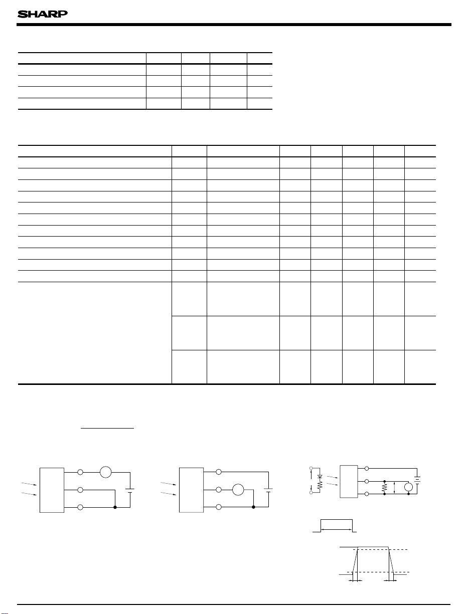
Test circuit 1 Test circuit 2 Test circuit 3
Ip=660nm
Vin
tr,tf=0.01µ s
Zo=50Ω
Vin
1.0V
IS474
T
IS474
Vcc
Io
GND
A
5V
Vcc
Ev
IS474
A
Io
GND
Ev
5V
(Vcc=5V, Ta=25˚C )
Test circuit
1.0
-14
- 140
(
1.3
- 500
mA
µ A
µ A
11
-
-
-
µ A
µ A
)
nA
nm
-
µs
-
µs
-
-
dB
-
dB
-
dB
Vcc
Io
Ro
GND
3.3kΩ
T=500µ s
Adjust Vin so that Vo waveform
may be of 1.0V amplitude
1
2
2
2
2
2
3
3
-
-
-
CRT
Vo
90%
IS474
Vcc
0V
10%
tr tf
 Loading...