

Page 1
SPECIAL WARNING
..............................
2
....................
3
ANTI-TIP BLOCK
................................................
3
....................
4
......................
4
CLEARANCES AND DIMENSIONS
MICROWAVE DRAWER
Page 2
If the information in this manual is not followed
exactly, a fi re or electrical shock may result that could cause
property damage, personal injury or death.
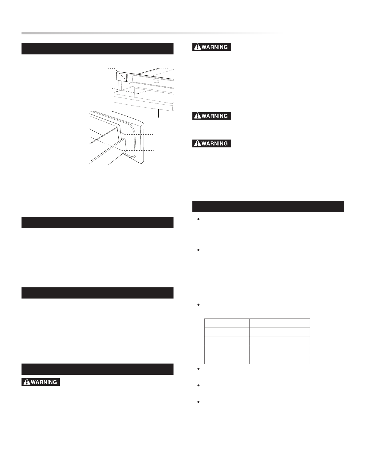
UNPACKING YOUR MICROWAVE DRAWER
Remove a ll packing
materials from inside
the Microwave Drawer.
DO NOT R EMOVE
THE WAVEG UIDE
located on the top of the
Microwave Drawer.
Remove the feature
mis a lig ned or b ent
Drawer guides and dents inside the cavity or on the front
the Microwave Drawer and contact your dealer or a SHARP
AUTHORIZED SERVICER.
•
Read all of the Installation Manual before installing the
Microwave Drawer.
Remove all packing material before connecting the electrical
•
Be sure to leave these instructions with the consumer.
Keep this manual with your Operation Manual for future
reference.
• As when using any microwave oven generating heat, there are
certain safety precautions you should follow. These are listed
in the Operation Manual. Read all and follow carefully.
• Be sure your Microwave Drawer is installed and grounded
properly by a qualifi ed installer or service technician.
Waveguide
Cover
Cavity
To reduce the risk of tipping, the Microwave
Drawer must be secured by a properly insta lled Anti-Tip
block.
• This Microwave Drawer must be electrically grounded in
• Make sure the wall coverings and the cabinets around the
Microwave Drawer can withstand the heat generated by the
Microwave Drawer.
Never leave children alone or unattended in
the area where a Microwave Drawer is in use.
Never leave the
Stepping, leaning or sitting on the drawer
may result in serious injuries and can also cause damage to the
Microwave Drawer.
•
Do not use the Microwave Drawer as a storage space.
This creates a potentially hazardous situation.
• Check that the time-of-day is in the display. If not, touch
to prevent unintended use.
Dimensions that are shown in Figures 1 and 2 must be used.
electrical outlet in the shaded area in the upper left-hand
corner of the cutout.
Contact surface must be solid and level. Pay special attention
to the fl oor on which the Microwave Drawer will sit. The
pounds).
installed for proper electrical supply.
Your oven can be built into a cabinet or wall by itself or
under a specifi c electric wall oven listed below.
Electrolux
E30EW75DSS1
Kitchen Aid
KEBC107KBLO
Frigidaire
PLEB30S8CCC
Viking
DES0100
Wolf
Be sure that the clearance of the fl oor between the wall oven
For updates of approved appliances that can be used adjacent
to the Microwave Drawer go to www.sharpusa.com.
The microwave interior will easily accommodate a 9” x 13”
CLEARANCES AND DIMENSIONS
IMPORTANT NOTES TO THE INSTALLER
IMPORTANT NOTES TO THE CONSUMER
IMPORTANT SAFETY INSTRUCTIONS
Page 3

28 1/8"
23 3/8"
14 19/32"
1 13/16"
door thickness
15 13/32"
30"
15"
auto drawer
opening
2"
4 11/16"
36"
countertop
height
30" *
cabinet min.
28 7/16"
opening
14 3/4"
opening
allow 1/4"
overlap
allow 7/16"
overlap
allow 3/4"
overlap
allow 3/4"
overlap
19"
to top of floor
4"
5"
electrical outlet
location
2x4 AntiTip block
floor must
support
100 lbs.
NOTE: Open Top
Cabinet illustrated
14 3/4"
to bottom
of Anti-Tip
block
3 1/2"
6"
23 1/2"
min depth
84"
wall
cabinet
30"
cabinet min.
28 7/16"
opening
14 3/4"
opening
allow 1/4"
overlap
allow 7/16"
overlap
allow 3/4"
overlap
allow 3/4"
overlap
*19"
to top of floor
(recommended)
4"
5"
2" minimum
electrical outlet
location
2x4 Anti-Tip block
optional wall oven
cutout illustrated
in sketch
floor must
support 100 lbs.
14 3/4"
to bottom
of Anti-Tip
block
3 1/2"
(6")
23 1/2"
min depth
Figures 1 and 2 contain many Microwave Drawer measurements
for reference when planning the drawerʼs location.
MICROWAVE DRAWER MEASUREMENTS
2x4 Anti-
Tip block
(6")
ANTI-TIP BLOCK INSTALLATION INSTRUCTIONS
To reduce the risk of tipping of the drawer, the Anti-Tip block
must be properly installed located 14 3/4-inches above the fl oor on
which the Microwave Drawer will sit. The 6-inch 2 x 4 Anti-Tip
block must be provided by the installer. See Figures 1, 2 and 4.
The Anti-Tip block prevents serious injury that might result from
If the Microwave Drawer is ever moved to a different location, the
Anti-Tip block must also be moved and installed. When installed
to the wall, make sure that the screws completely penetrate the
totally stable. When fastening, be sure that the screws do not
penetrate electrical wiring or plumbing.
ANTI-TIP BLOCK
Page 4

The name plate, including model and serial number, is located
Refer to the Operation Manual for cleaning instructions.
Read the BEFORE YOU CALL and operating instruction sections
in your Operation Manual. It may save you time and expense.
The list includes common occurrences that are not the result of
Refer to the warranty in your Operation Manual for Sharpʼs
toll-free service number and address. Please call or write if you
have inquiries about your microwave product and/or need to
TIN S EB 417M RR0
J
4 Screws
Parts Supplied
cabinet opening. Plug the power supply cord
into the electrical outlet.
the oven and the wall.
with the face of the cabinet.
4. Secure the drawer with the 4 screws supplied. See Figure 6.
ELECTRICAL OUTLET
4"
5"
electrical outlet location
2x4 Anti-
Tip block
(6")
The electrical requirements are a 120 volt 60 Hz, AC only, 15
The drawer is equipped with a 3-prong grounding plug. It must
be plugged into a wall receptacle that is properly installed and
electrician install a correct wall receptacle.
Note:
If you have any questions about the grounding or electrical
instructions, consult a qualifi ed electrician or service person.
This appliance must be grounded. The Microwave Drawer is
equipped with a cord having a grounding wire with a grounding
plug. It must be plugged into a wall receptacle that is properly
installed and grounded in accordance with t he National
Electrical Code and local codes
electric shock by providing
current.
– Improper use
in a risk of electric shock.
3-Prong Plug
Grounding Pin
3-Prong Receptacle
Ground Receptacle Box
Permanent and Correct Installation
Grounding Adapter
Ground Receptacle Box
Screw
Tab for Grounding Screw
Temporary Use
DRAWER INSTALLATION
GROUNDING INSTRUCTIONS
MODEL AND SERIAL NUMBER LOCATION
CARE, CLEANING AND MAINTENANCE
BEFORE YOU CALL FOR SERVICE
 Loading...