

Page 1
MINI COMPONENT SYSTEM
MINI-CHAÎNE
SISTEMA MINI COMPONENTE
SISTEMA MINI COMPONENTE
MODEL
MODÈLE
MODELO
MODELO
The illustrations printed in this operation manual are for the model CD-MPX200W
Les illustrations utilisées dans ce mode d’emploi sont pour le modèle CD-MPX200W.
Las ilustraciones impresas en este manual de manejo son del modelo CD-MPX200W.
As ilustrações impressas neste manual de operações são para o modelo CD-MPX200W.
CD-MPX200W
.
CD-MPX200W
CD-MPX500W
OPERATION MANUAL
MODE D’EMPLOI
MANUAL DE MANEJO
MANUAL DE OPERAÇÃO
CD-MPX500W
ENGLISH
FRANÇAIS
ESPAÑOL
PORTUGUÊS
Please refer to pages E-1 to E-40.
Se reporter aux pages F-1 à F-40.
Consulte las páginas S-1 a S-40.
Favor consultar as páginas P-1 a P-40.
Page 2

CD-MPX200W
CD-MPX500W
ENGLISH
Special notes
WARNINGS
When the ON/STAND-BY button is set at STAND-BY position,
mains voltage is still present inside the unit. When the
ON/STAND-BY button is set at STAND-BY position, the unit may
be brought into operation by the timer mode or remote control.
This unit contains no user serviceable parts. Never remove covers
unless qualified to do so. This unit contains dangerous voltages,
always remove mains plug from the socket before any service
operation and when not in use for a long period.
To prevent fire or shock hazard, do not expose this appliance to
dripping or splashing. No objects filled with liquids, such as vases,
shall be placed on the apparatus.
Do not turn the volume on to full at switch on and listen to music
at moderate levels. Excessive sound pressure from earphones
and headphones can cause hearing loss.
Note:
Audio-visual material may consist of copyrighted works which must
not be recorded without the authority of the owner of the copyright.
Please refer to the relevant laws in your country.
NOTE
This equipment has been tested and found to comply with the limits
for a Class B digital device, pursuant to Part 15 of the FCC Rules.
These limits are designed to provide reasonable protection against
harmful interference in a residential installation. This equipment
generates, uses, and can radiate radio frequency energy and, if not
Important Instruction
installed and used in accordance with the instructions, may cause
harmful interference to radio communications. However, there is no
guarantee that interference will not occur in a particular installation.
If this equipment does cause harmful interference to radio or
television reception, which can be determined by turning the
equipment off and on, the user is encouraged to try to correct the
interference by one or more of the following measures:
ENGLISH
Reorient or relocate the receiving aerial.
Increase the separation between the equipment and receiver.
Connect the equipment into an outlet on a circuit different from
that to which the receiver is connected.
Consult the dealer or an experienced radio/TV technician for help.
WARNING
FCC Regulations state that any unauthorised changes or
modifications to this equipment not expressly approved by the
manufacturer could void the user's authority to operate this
equipment.
CAUTION
This product is classified as a CLASS 1 LASER product.
Use of controls, adjustments or performance of procedures other
than those specified herein may result in hazardous radiation
exposure.
As the laser beam used in this compact disc player is harmful to
the eyes, do not attempt to disassemble the cabinet. Refer
servicing to qualified personnel only.
Laser Diode Properties
Material: AIGaAs
Wavelength: 790 nm
Emission Duration: continuous
Laser Output: max. 0.6 mW
CAUTION-INVISIBLE LASER RADIATION WHEN OPEN.
DO NOT STARE INTO BEAM OR VIEW DIRECTLY WITH
OPTICAL INSTRUMENTS.
WARNUNG-UNSICHTBARE LASERSTRAHLUNG WENN GERÄT
GEÖFFNET. NICHT IN DIE STRAHLUNG SCHAUEN ODER
DIREKT MIT OPTISCHEN HILFSMITTELN BETRACHTEN.
ATTENTION-RAYON LASER INVISIBLE EN CAS D'OUVERTURE.
NE PAS REGARDER LE FAISCEAU DIRECTEMENT OU AVEC DES
INSTRUMENTS OPTIQUES.
E-1
Page 3
Introduction
Thank you for purchasing this SHARP product. To obtain the best
performance from this product, please read this manual carefully. It
will guide you in operating your SHARP product.
CD-MPX200W Mini Component System consisting of
CD-MPX200W (main unit), CP-MPX200 (speaker system).
CD-MPX500W Mini Component System consisting of
CD-MPX500W (main unit), CP-MPX500 (speaker system).
Special Note
Supply of this product does not convey a license nor imply any right
to distribute content created with this product in revenue-generating
broadcast systems (terrestrial, satellite, cable and/or other
distribution channels), revenue-generating streaming applications
(via Internet, intranets and/or other networks), other revenuegenerating content distribution systems (pay-audio or audio-ondemand applications and the like) or on revenue-generating physical
media (compact discs, digital versatile discs, semiconductor chips,
hard drives, memory cards and the like). An independent license for
such use is required. For details, please visit http://mp3licensing.com
MPEG Layer-3 audio coding technology licensed from Fraunhofer
IIS and Thomson.
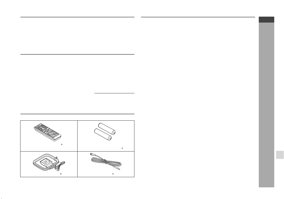
Accessories
Please confirm that only the following accessories are included.
Remote control 1 “AA” size battery (UM/SUM-3,
R6, HP-7 or similar) 2
Contents
Page
General Information
Precautions . . . . . . . . . . . . . . . . . . . . . . . . . . . . . . . . . . . . . . . . . . 3
Controls and indicators . . . . . . . . . . . . . . . . . . . . . . . . . . . . . .4 - 6
Preparation for Use
System connections. . . . . . . . . . . . . . . . . . . . . . . . . . . . . . . . 7 - 10
Remote control . . . . . . . . . . . . . . . . . . . . . . . . . . . . . . . . . . . . . 11
Basic Operation
General control . . . . . . . . . . . . . . . . . . . . . . . . . . . . . . . . . . . . . 12
Setting the clock (Remote control only) . . . . . . . . . . . . . . . . . 13
CD or MP3/WMA disc Playback
Listening to a CD or MP3/WMA disc . . . . . . . . . . . . . . . . .14 - 17
Advanced CD or MP3/WMA disc playback . . . . . . . . . . . . 18 - 20
MP3/WMA navigation (only for MP3/WMA files) . . . . . . . .21 - 24
Radio
Listening to the radio . . . . . . . . . . . . . . . . . . . . . . . . . . . . . .25 - 26
Tape Playback
Listening to a cassette tape (TAPE 1 or TAPE 2) . . . . . . .27 - 28
Tape Recording
Recording on a cassette tape . . . . . . . . . . . . . . . . . . . . . . . 28 - 30
Advanced Features
Timer and sleep operation (Remote control only) . . . . . . 31 - 34
Enhancing your system . . . . . . . . . . . . . . . . . . . . . . . . . . .35 - 36
References
Troubleshooting chart . . . . . . . . . . . . . . . . . . . . . . . . . . . . .36 - 38
Maintenance . . . . . . . . . . . . . . . . . . . . . . . . . . . . . . . . . . . . . . . . 39
Specifications . . . . . . . . . . . . . . . . . . . . . . . . . . . . . . . . . . . .39 - 40
CD-MPX200W
CD-MPX500W
ENGLISH
General Information
AM loop aerial 1 FM aerial 1
E-2
Page 4
CD-MPX200W
CD-MPX500W
ENGLISH
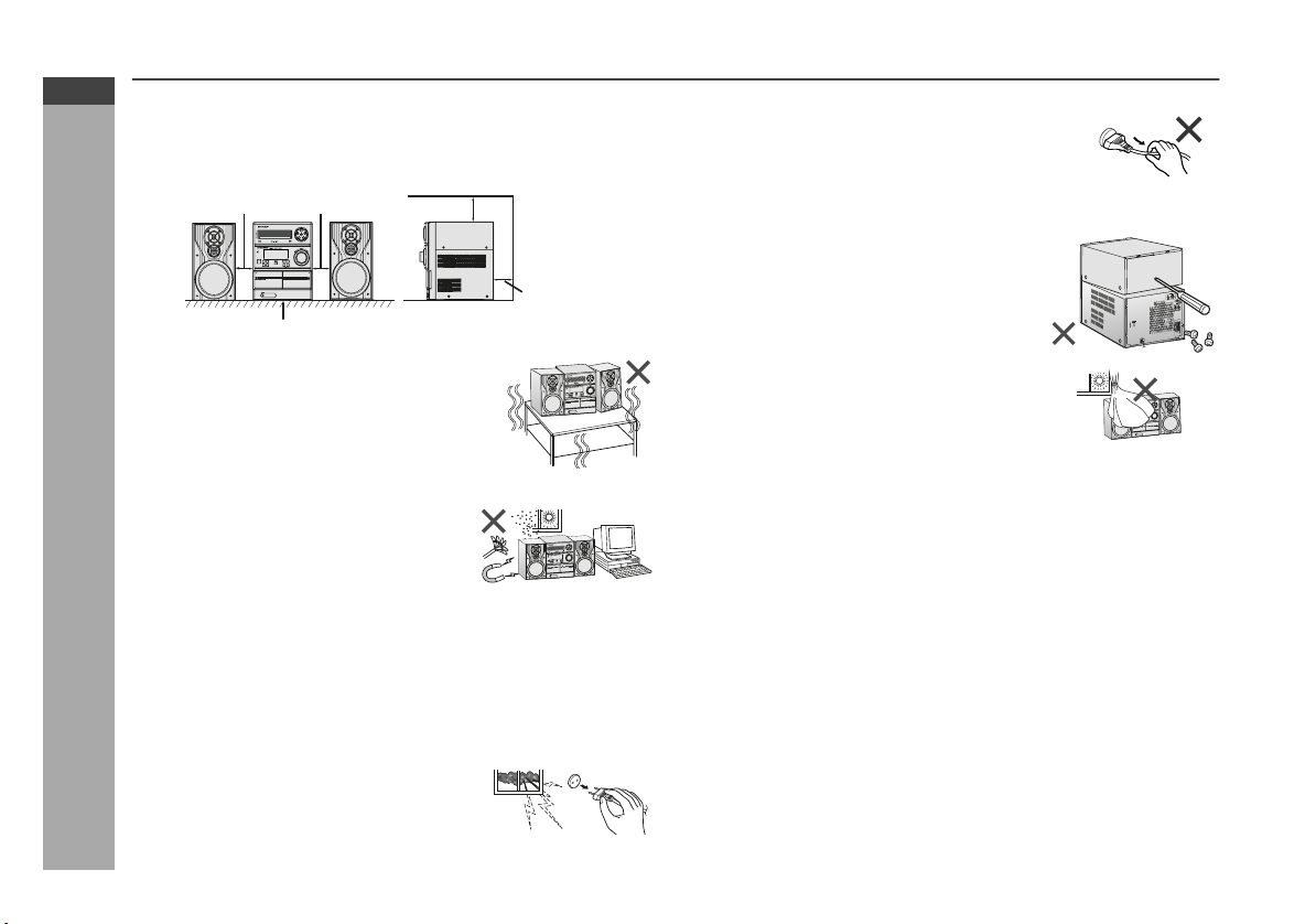
Precautions
General
Please ensure that the equipment is positioned in a well ventilated
area and ensure that there is at least 10 cm (4") of free space
along the sides, top and back of the equipment.
10 cm (4")
Use the unit on a firm, level surface free from
vibration.
Keep the unit away from direct sunlight,
strong magnetic fields, excessive dust,
humidity and electronic/electrical
equipment (home computers,
facsimiles, etc.) which generate
General Information
electrical noise.
Do not place anything on top of the unit.
Do not expose the unit to moisture, to temperatures higher than
C (140˚F) or to extremely low temperatures.
60
˚
If your system does not work properly, disconnect the AC power
lead from the wall socket. Plug the AC power lead back in, and
then turn on your system.
In case of an electrical storm, unplug the
unit for safety.
E-3
10 cm (4")
Table
10 cm (4")
10 cm (4")
Hold the AC power plug by the head when
removing it from the wall socket, as pulling
the lead can damage internal wires.
The AC power plug is used as disconnect
device and shall always remain readily
operable.
Do not remove the outer cover, as this
may result in electric shock. Refer
internal service to your local SHARP
service facility.
T
U
P
N
I
C
A
The ventilation should not be impeded by
covering the ventilation openings with
items, such as newspapers, tablecloths,
curtains, etc.
No naked flame sources, such as lighted candles, should be
placed on the apparatus.
Attention should be drawn to the environmental aspects of battery
disposal.
The apparatus is designed for use in moderate climate.
This unit should only be used within the range of 5
C - 35˚C
˚
(41˚F - 95˚F).
Warning:
The voltage used must be the same as that specified on this unit.
Using this product with a higher voltage other than that which is
specified is dangerous and may result in a fire or other type of
accident causing damage. SHARP will not be held responsible for
any damage resulting from use of this unit with a voltage other than
that which is specified.
Volume control
The sound level at a given volume setting depends on speaker
efficiency, location, and various other factors. It is advisable to avoid
exposure to high volume levels. Do not turn the volume on to full at
switch on and listen to music at moderate levels. Excessive sound
pressure from earphones and headphones can cause hearing loss.
Page 5
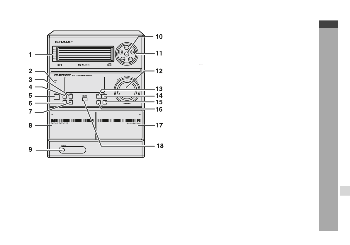
Controls and indicators
Front panel
1. Disc Trays . . . . . . . . . . . . . . . . . . . . . . . . . . . . . . . . . . . . . . . 15
2. Timer Indicator . . . . . . . . . . . . . . . . . . . . . . . . . . . . . . . . . . . 32
3. Tuner (Band) Button . . . . . . . . . . . . . . . . . . . . . . . . . . . . . . 25
4. CD Button . . . . . . . . . . . . . . . . . . . . . . . . . . . . . . . . . . . . . . . 15
5. ON/STAND-BY Button . . . . . . . . . . . . . . . . . . . . . . . . . . . . . 12
6. Tape (1 2) Button . . . . . . . . . . . . . . . . . . . . . . . . . . . . . . . 27
7. Game/Aux Button . . . . . . . . . . . . . . . . . . . . . . . . . . . . . . . . . 35
8. Tape 1 Cassette Compartment . . . . . . . . . . . . . . . . . . . . . . 27
9. Headphone Socket . . . . . . . . . . . . . . . . . . . . . . . . . . . . . . . . 36
10. Disc Tray Open/Close Button . . . . . . . . . . . . . . . . . . . . . . . 15
11. Disc Number Select Buttons . . . . . . . . . . . . . . . . . . . . . . . . 15
12. Volume Control . . . . . . . . . . . . . . . . . . . . . . . . . . . . . . . . . . 12
13. CD or Tape Stop Button . . . . . . . . . . . . . . . . . . . . . . . . 16, 28
14. CD Play or Repeat, Tape Play Button . . . . . . . . . . . 15, 19, 27
15. CD Track Up or Fast Forward, Tape 2 Fast Forward,
Tuner Preset Up, Time Up Button . . . . . . . 13, 16, 26, 28, 31
16. CD Track Down or Fast Reverse, Tape 2 Rewind,
Tuner Preset Down, Time Down Button . . . 13, 16, 26, 28, 31
17. Tape 2 Cassette Compartment . . . . . . . . . . . . . . . . . . . . . . 27
18. Remote Sensor . . . . . . . . . . . . . . . . . . . . . . . . . . . . . . . . . . . 11
Reference page
CD-MPX200W
CD-MPX500W
ENGLISH
General Information
E-4
Page 6
CD-MPX200W
CD-MPX500W
ENGLISH
Controls and indicators (continued)
12 3 45 678 9
General Information
1
2
3
E-5
16 17
18
19
4
5
6
7
8
9
11 12 13
10
15
14
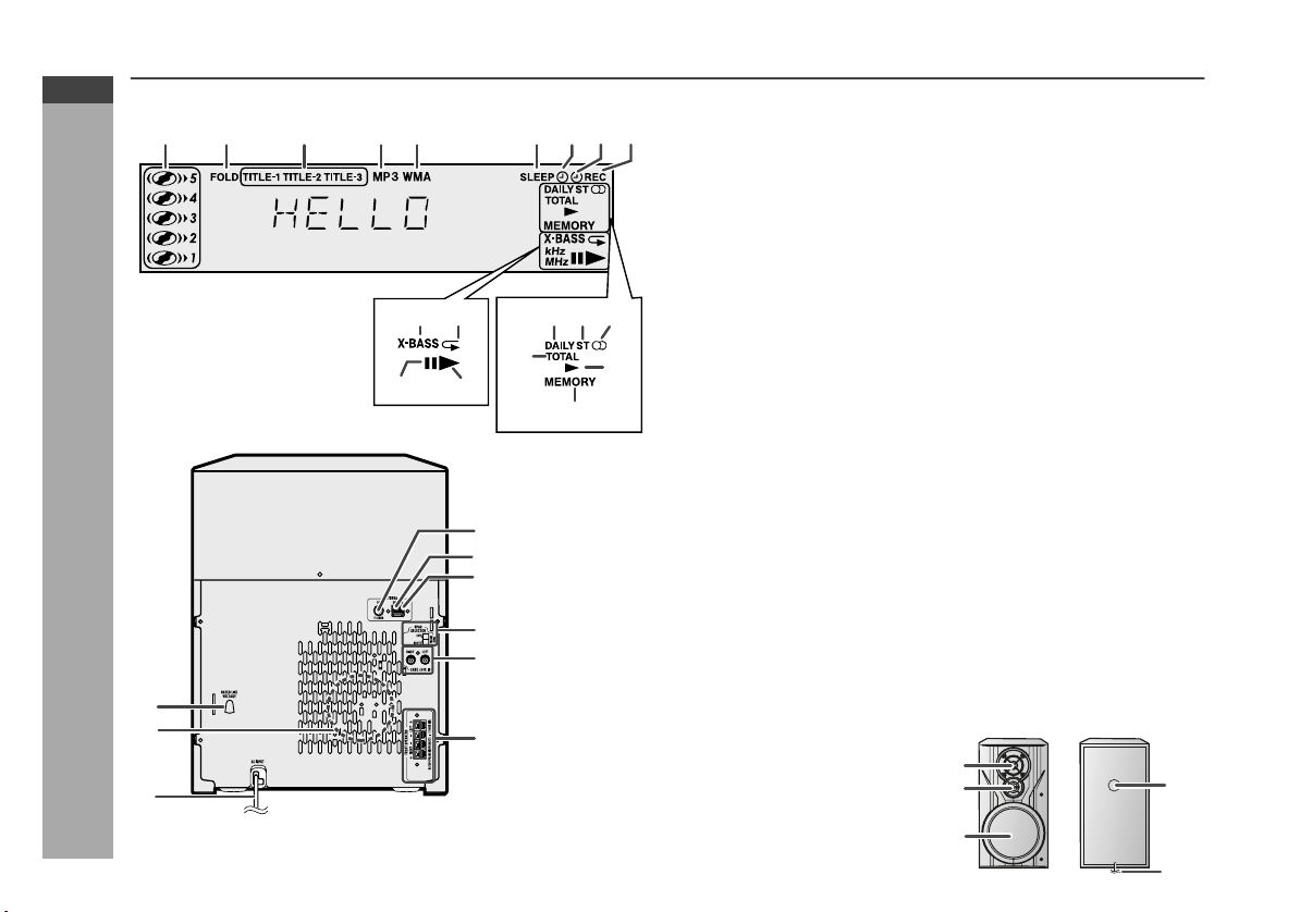
Display
1. Disc Number Indicators . . . . . . . . . . . . . . . . . . . . . . . . . . . . 18
2. MP3/WMA Folder Indicator . . . . . . . . . . . . . . . . . . . . . . . . . 21
3. MP3/WMA Title Indicators . . . . . . . . . . . . . . . . . . . . . . . . . . 21
4. MP3 Indicator . . . . . . . . . . . . . . . . . . . . . . . . . . . . . . . . . . . . 15
5. WMA Indicator . . . . . . . . . . . . . . . . . . . . . . . . . . . . . . . . . . . 15
6. Sleep Indicator . . . . . . . . . . . . . . . . . . . . . . . . . . . . . . . . . . . 34
7. Timer Play Indicator . . . . . . . . . . . . . . . . . . . . . . . . . . . . . . . 32
8. Timer Recording Indicator . . . . . . . . . . . . . . . . . . . . . . . . . . 32
9. Tape 2 Record Indicator . . . . . . . . . . . . . . . . . . . . . . . . . . . 29
10. MP3/WMA Total Indicator . . . . . . . . . . . . . . . . . . . . . . . . . . 22
11. Daily Timer Indicator . . . . . . . . . . . . . . . . . . . . . . . . . . . . . . 32
12. FM Stereo Mode Indicator . . . . . . . . . . . . . . . . . . . . . . . . . . 25
13. FM Stereo Receiving Indicator . . . . . . . . . . . . . . . . . . . . . . 25
14. Tape Play Indicator . . . . . . . . . . . . . . . . . . . . . . . . . . . . . . . 27
15. Memory Indicator . . . . . . . . . . . . . . . . . . . . . . . . . . . . . . 20, 26
16. Extra Bass Indicator . . . . . . . . . . . . . . . . . . . . . . . . . . . . . . . 12
17. Disc Repeat Play Indicator . . . . . . . . . . . . . . . . . . . . . . . . . 19
18. Disc Pause Indicator . . . . . . . . . . . . . . . . . . . . . . . . . . . . . . 16
19. Disc Play Indicator . . . . . . . . . . . . . . . . . . . . . . . . . . . . . . . . 15
Rear panel
1. AC Voltage Selector . . . . . . . . . . . . . . . . . . . . . . . . . . . . . . . 10
2. Cooling Fan (FOR CD-MPX500W ONLY) . . . . . . . . . . . . . . . 9
3. AC Power Lead . . . . . . . . . . . . . . . . . . . . . . . . . . . . . . . . . . . 10
4. FM 75 Ohms Aerial Socket . . . . . . . . . . . . . . . . . . . . . . . . . . 8
5. AM Aerial Earth Terminal . . . . . . . . . . . . . . . . . . . . . . . . . . . . 8
6. AM Loop Aerial Terminal . . . . . . . . . . . . . . . . . . . . . . . . . . . . 8
7. Span Selector Switch . . . . . . . . . . . . . . . . . . . . . . . . . . . . . . 10
8. Game/Aux Input Sockets . . . . . . . . . . . . . . . . . . . . . . . . . . . 35
9. Front Speaker Terminals . . . . . . . . . . . . . . . . . . . . . . . . . . . . 8
Speaker System
1. Tweeter
2. Super Tweeter
3. Woofer
4. Bass Reflex Duct
5. Speaker Wire
11
2
Reference page
Reference page
4
3
6
5
Page 7
CD-MPX200W
CD-MPX500W
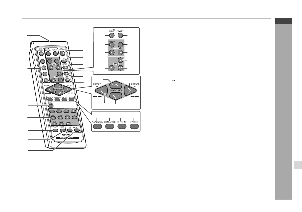
Remote control
1
13
14
8
15
9
10
2
3
4
16
11
22
12
24
25
26 27 28 29
17
18
19
20
21
23
5
6
7
1. Remote Control Transmitter . . . . . . . . . . . . . . . . . . . . . . . . 11
2. Disc Number Select Buttons . . . . . . . . . . . . . . . . . . . . . . . . 15
3. Clock/Timer Button . . . . . . . . . . . . . . . . . . . . . . . . . . . . 13, 31
4. Character Input/Disc Direct Search Buttons . . . . . . . . 18, 23
5. Equaliser Mode Select Button . . . . . . . . . . . . . . . . . . . . . . 12
6. Extra Bass/Demo Button . . . . . . . . . . . . . . . . . . . . . . . . . . . 12
7. Volume Up and Down Buttons . . . . . . . . . . . . . . . . . . . . . . 12
8. ON/STAND-BY Button . . . . . . . . . . . . . . . . . . . . . . . . . . . . . 12
9. CD Button . . . . . . . . . . . . . . . . . . . . . . . . . . . . . . . . . . . . . . . 15
10. Tuner (Band) Button . . . . . . . . . . . . . . . . . . . . . . . . . . . . . . 25
11. Tape (1 2) Button . . . . . . . . . . . . . . . . . . . . . . . . . . . . . . . 27
12. Game/Aux Button . . . . . . . . . . . . . . . . . . . . . . . . . . . . . . . . . 35
13. Disc Clear/Dimmer Button . . . . . . . . . . . . . . . . . . . . . . 12, 20
14. Disc Random Button . . . . . . . . . . . . . . . . . . . . . . . . . . . . . . 19
15. Disc Stop Button . . . . . . . . . . . . . . . . . . . . . . . . . . . . . . . . . 16
16. Tape Stop Button . . . . . . . . . . . . . . . . . . . . . . . . . . . . . . . . . 27
17. Memory Button . . . . . . . . . . . . . . . . . . . . . . . . . . 13, 20, 26, 31
18. Disc Pause Button . . . . . . . . . . . . . . . . . . . . . . . . . . . . . . . . 16
19. Disc Play or Repeat Button . . . . . . . . . . . . . . . . . . . . . . 15, 19
20. Tape Play Button . . . . . . . . . . . . . . . . . . . . . . . . . . . . . . . . . 27
21. Tape 2 Record Pause Button . . . . . . . . . . . . . . . . . . . . . . . 29
22. Tuning Up, Cursor Up Button . . . . . . . . . . . . . . . . . . . . 21, 25
23. Disc Track Up or Fast Forward, Tape 2 Fast Forward,
Tuner Preset Up, Time Up, Cursor Right Button . . . . . . . . . .
. . . . . . . . . . . . . . . . . . . . . . . . . . . . . . . . . . . . 13, 16, 26, 28, 31
24. Disc Track Down or Fast Reverse, Tape 2 Rewind,
Tuner Preset Down, Time Down, Cursor Left Button . . . . . .
. . . . . . . . . . . . . . . . . . . . . . . . . . . . . . . . . . . . 13, 16, 26, 28, 31
25. Tuning Down, Cursor Down Button . . . . . . . . . . . . . . . 21, 25
26. MP3/WMA Navigation Mode Select Button . . . . . . . . . . . . 21
27. Character Button . . . . . . . . . . . . . . . . . . . . . . . . . . . . . . . . . 21
28. MP3/WMA Display Button . . . . . . . . . . . . . . . . . . . . . . . . . . 17
29. Enter Button . . . . . . . . . . . . . . . . . . . . . . . . . . . . . . . . . . . . . 21
Reference page
ENGLISH
General Information
E-6
Page 8
CD-MPX200W
CD-MPX500W
ENGLISH
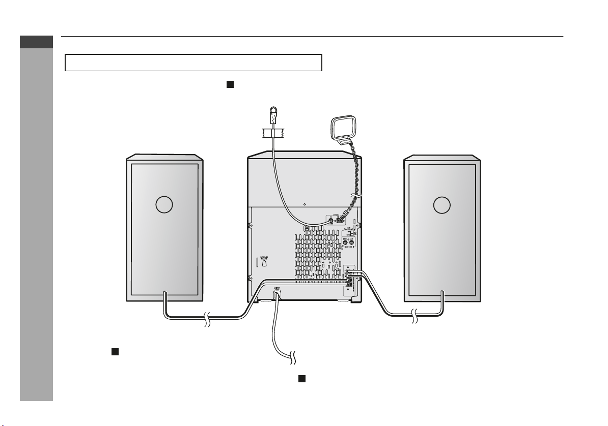
System connections
Make sure to unplug the AC power lead before any connections.
Aerial connection (see page 8)
FM aerial
AM loop aerial
Preparation for Use
Speaker connection
(see page 8)
E-7
Right speaker
Left speaker
To a Wall socket
AC power connection (see page 10)
Page 9
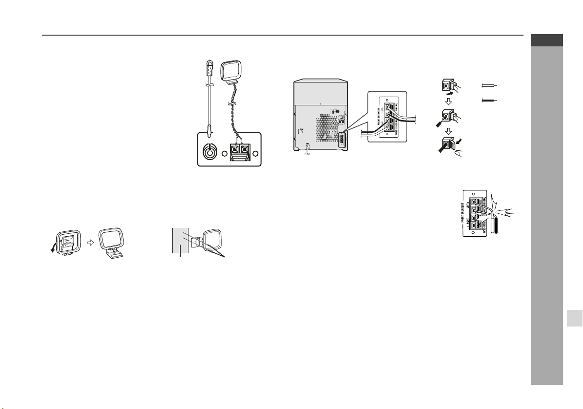
Aerial connection
Supplied FM aerial:
Connect the FM aerial wire to the FM
75 OHMS socket and position the FM
aerial wire in the direction where the
FM
aerial
AM loop
aerial
strongest signal can be received.
Supplied AM loop aerial:
Connect the AM loop aerial to the AM
and GND terminals. Position the AM
loop aerial for optimum reception.
Place the AM loop aerial on
a shelf,
ANTENNA
FM
GND
AM
etc., or attach it to a stand or a wall with
screws (not supplied).
75 OHMS
Note:
Placing the aerial on the unit or near the AC power lead may cause
noise pickup. Place the aerial away from the unit for better reception.
Installing the AM loop aerial:
< Assembling > < Attaching to the wall >
Wall Screws (not supplied)
Speaker connection
Connect the black wire to the FRONT SPEAKERS minus (-) terminal,
and the red wire to the FRONT SPEAKERS plus (+) terminal.
Red
Black
Caution:
Use speakers with an impedance of 6 ohms
or more, as lower impedance speakers can
damage the unit.
Do not mistake the right and the left
channels. The right speaker is the one on the
right side when you face the unit.
Do not let the bare speaker wires touch
each other.
Incorrect
Do not stand or sit on the speakers. You may
be injured.
Do not allow any objects to fall into or to be
placed in the bass reflex duct.
CD-MPX200W
CD-MPX500W
ENGLISH
Preparation for Use
E-8
Page 10
CD-MPX200W
CD-MPX500W
ENGLISH
System connections (continued)
Cooling fan: (FOR CD-MPX500W ONLY)
The main unit is built with a cooling fan at the rear of the unit for
improved cooling. Please do not cover the opening of the fan with
any obstacles, as this will block proper ventilation.
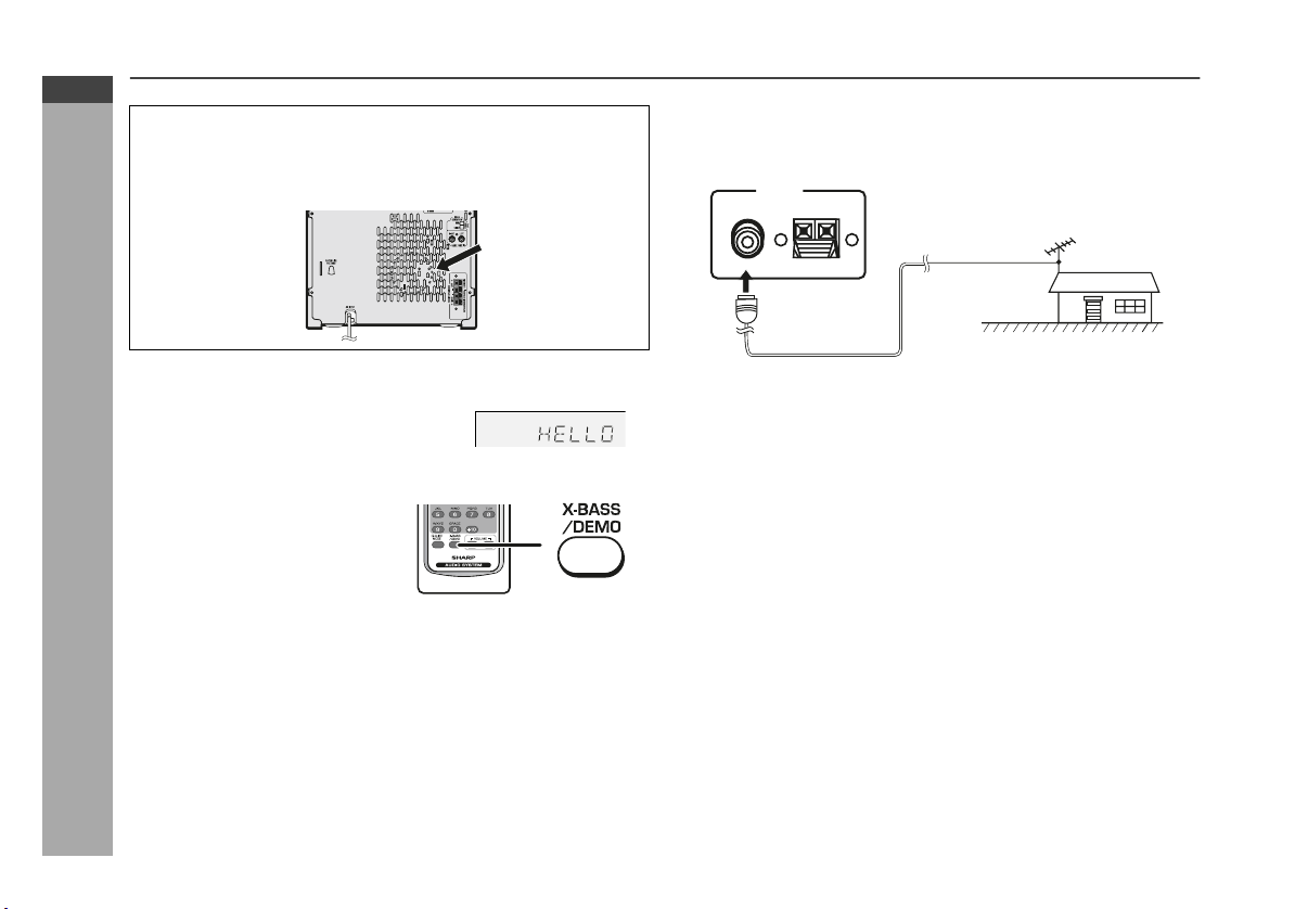
External FM aerial
Use an external FM aerial if you require better reception. Consult
your dealer.
ANTENNA
FM
GND
AM
75 OHMS
75 ohms
coaxial cable
External FM aerial
Demonstration mode
The first time the unit is plugged in, the
unit will enter the demonstration mode.
You will see words scroll.
To cancel the demonstration mode:
When the unit is in the power
stand-by mode (demonstration
mode), press the X-BASS/DEMO
button. The unit will enter the low
power consumption mode.
Preparation for Use
To return to the demonstration mode:
When the unit is in the power stand-by mode, press the
X-BASS/DEMO button again.
Note:
When the power is on, the X-BASS/DEMO button can be used to
select the extra bass mode.
E-9
Note:
When an external FM aerial is used, disconnect the supplied FM
aerial wire.
Page 11
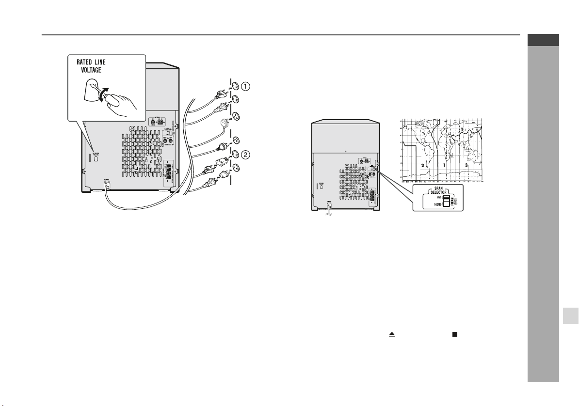
AC Plug Adaptor
In areas (or countries) where the wall socket as shown in illustration
2 is used, connect the unit using the AC plug adaptor supplied with
the unit, as illustrated. The AC plug adaptor is not included in areas
where the and wall socket and AC power plug can be directly
connected (see illustration 1).
Setting the FM/AM span selector
CD-MPX200W
CD-MPX500W
ENGLISH
Setting the AC voltage selector
Check the setting of the AC voltage selector located on the rear
panel before plugging the unit into the wall socket. If necessary,
adjust the selector to correspond to the AC power voltage used in
your area.
Turn the selector with a screwdriver until the appropriate
voltage number appears in the window (110 V, 127 V, 220V or
230 V-240 V AC).
Connecting the AC power lead
After checking all the connections have been made correctly, plug
the AC power lead of this unit into the wall socket. If you plug the unit
first, the unit will enter the demonstration mode (see page 9).
Notes:
The unit will start the tape initialisation when plugged into the wall
socket. During this process, initialising sound will be heard and
the unit cannot be turned on. Wait until the process is finished.
Unplug the AC power lead from the wall socket if the unit will not
be in use for a prolonged period of time.
The International Telecommunication Union (ITU) has established
that member countries should maintain either a 100 kHz or a 50 kHz
interval between broadcasting frequencies of FM stations and 10
kHz or 9 kHz for AM station. The illustration shows the 50/9 kHz
zones (regions 1 and 3), and the 100/10 kHz zone (region 2).
Before using the unit, set the SPAN SELECTOR switch (on the rear
panel) to the interval (span) of your area.
To change the tuning zone:
1 Press the ON/STAND-BY button to enter the stand-by mode.
2 Set the SPAN SELECTOR switch (on the rear panel) as follows.
For 50 kHz FM interval (9 kHz in AM) → 50/9
For 100 kHz FM interval (10 kHz in AM) → 100/10
3 Whilst pressing down the button and the button, press the
TUNER (BAND) button until "CLEAR ALL" appears.
Caution:
This operation will erase all data stored in memory including clock,
timer settings, tuner preset, and CD programme.
Preparation for Use
E-10
Page 12
CD-MPX200W
CD-MPX500W
ENGLISH
Remote control
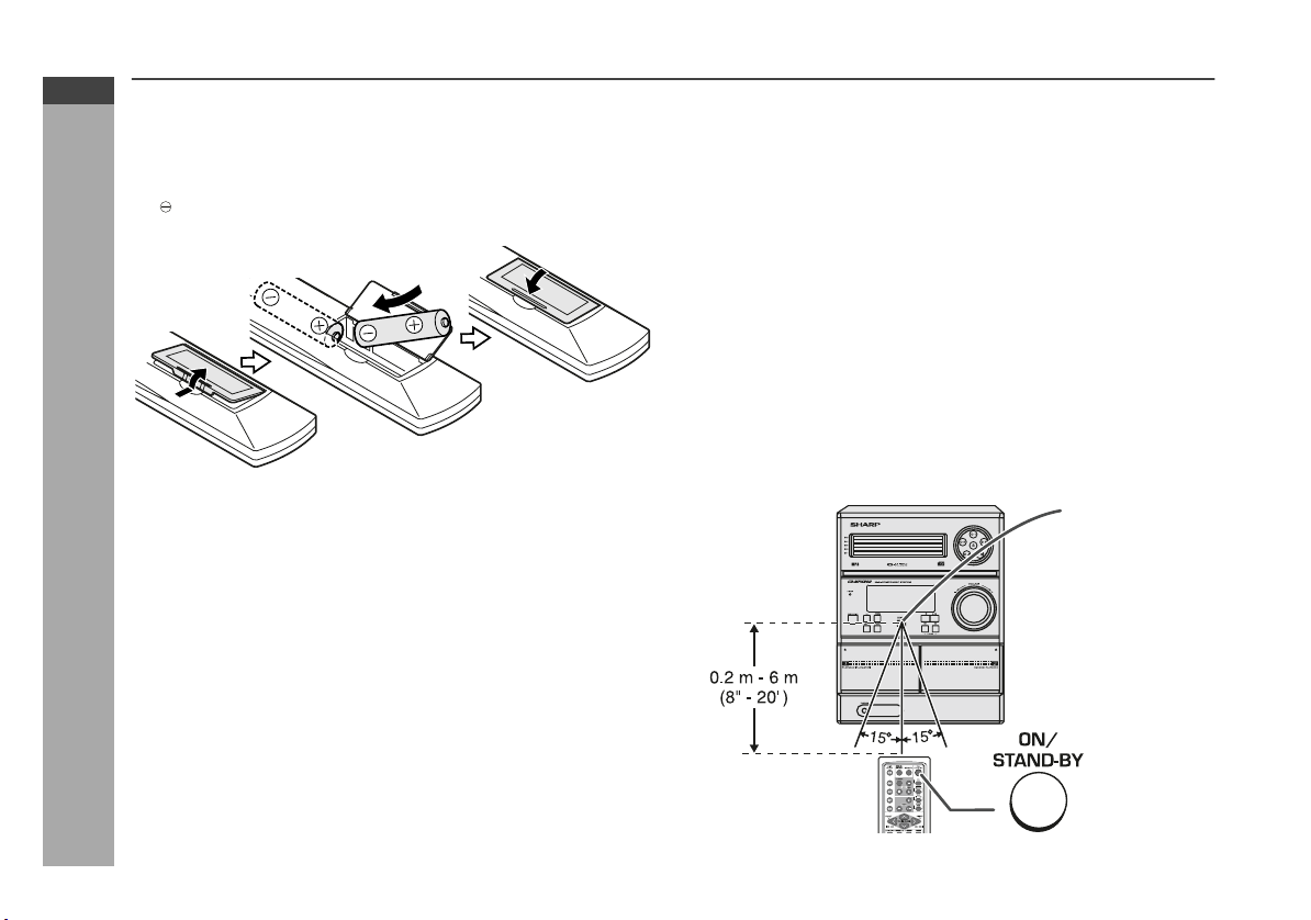
Battery installation
1 Open the battery cover.
2 Insert the supplied batteries according to the direction
indicated in the battery compartment.
When inserting or removing the batteries, push them towards the
battery terminals.
3 Close the battery cover.
Precautions for battery use:
Replace all old batteries with new ones at the same time.
Do not mix old and new batteries.
Remove the batteries if the unit will not be used for long periods
Preparation for Use
of time. This will prevent potential damage due to battery leakage.
Caution:
Do not use rechargeable batteries (nickel-cadmium battery, etc.).
Installing the batteries incorrectly may cause the unit to
malfunction.
Batteries (battery pack or batteries installed) shall not be exposed
to excessive heat such as sunshine, fire or the like.
Battery removal:
Open the battery cover and pull up the battery to take out.
Notes concerning use:
Replace the batteries if the operating distance is reduced or if the
operation becomes erratic. Purchase 2 “AA” size batteries (UM/
SUM-3, R6, HP-7 or similar).
Periodically clean the transmitter on the remote control and the
sensor on the unit with a soft cloth.
Exposing the sensor on the unit to strong light may interfere with
operation. Change the lighting or the direction of the unit.
Keep the remote control away from moisture, heat, shock, and
vibrations.
Test of the remote control
Check the remote control after checking all the connections (see
pages 7 - 10).
Point the remote control directly at the remote sensor on the unit.
The remote control can be used within the range shown below:
Press the ON/STAND-BY button. Does the power turn on? Now, you
can enjoy the music.
Remote sensor
E-11
Page 13
General control
To turn the power on
Press the ON/STAND-BY button to turn the power on.
After use:
Press the ON/STAND-BY button to enter the power stand-by mode.
Display Brightness control
To dim the display brightness, hold down the CLEAR/DIMMER
button on the remote control for 2 seconds or more.
Volume auto fade-in
If you turn off and on the main unit with the volume set to 27 or
higher, the volume starts at 16 and fades in to the last set level.
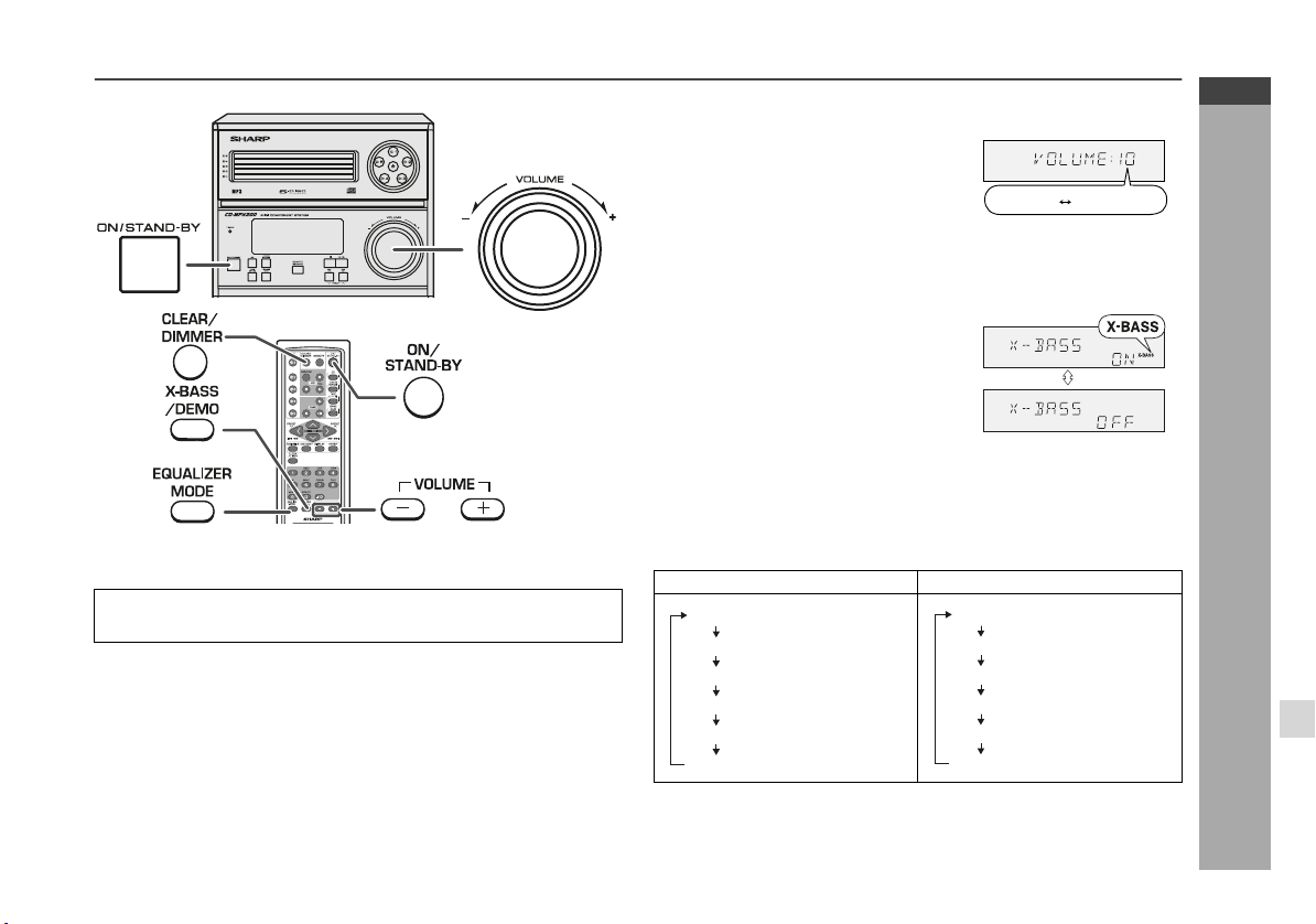
Volume control
Main unit operation:
When the VOLUME control is turned
clockwise, the volume will increase.
When it is turned anti-clockwise, the
volume will decrease.
.....
30 MAXIMUM0
Remote control operation:
Press the VOLUME (+ or -) button to
increase or decrease the volume.
Bass Control (X-BASS)
When the X-BASS/DEMO button is
pressed, the unit will enter the extra bass
mode. To cancel this mode, press the
X-BASS/DEMO button again.
Equaliser
When the power is first turned on, the unit will enter FLAT mode.
When the EQUALIZER MODE button is pressed, the current mode
setting will be displayed. To change to a different mode, press the
EQUALIZER MODE button repeatedly until the desired sound mode
appears.
In CD/TUNER/TAPE mode In GAME/AUX mode
No equalisation.
FLAT
ROCK
CLASSIC
POPS
VOCALS
JAZZ
No equalisation.
For rock music.
For classical music.
For pop music.
Vocals are enhanced.
For jazz.
FLAT
ROCK
CLASSIC
ACTION
SPORTS
RACING
For rock music.
For classical music.
For action games.
For sports games.
For car racing games.
CD-MPX200W
CD-MPX500W
ENGLISH
Basic Operation
E-12
Page 14
CD-MPX200W
CD-MPX500W
ENGLISH
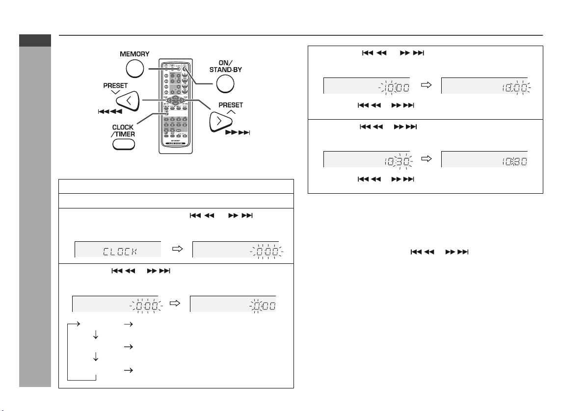
Setting the clock (Remote control only)
In this example, the clock is set for the 24-hour (0:00) display.
1 Press the ON/STAND-BY button to turn the power on.
2 Press the CLOCK/TIMER button.
3 Within 10 seconds, press the or button to
select “CLOCK”, and press the MEMORY button.
Basic Operation
4 Press the or button to select 24-hour or
12-hour display and then press the MEMORY button.
“AM 12:00”
“AM 0:00”
E-13
“0:00”
The 24-hour display will appear.
(0:00 - 23:59)
The 12-hour display will appear.
(AM 12:00 - PM 11:59)
The 12-hour display will appear.
(AM 0:00 - PM 11:59)
5 Press the or button to adjust the hour and
then press the MEMORY button.
Press the or button once to advance the time by
1 hour. Hold it down to advance continuously.
6 Press the or button to adjust the minutes and
then press the MEMORY button.
Press the or button once to advance the time by
1 minute. Hold it down to change the time in 5-minute intervals.
To confirm the time display:
[When the unit is in the stand-by mode]
Press the CLOCK/TIMER button.
The time display will appear for about 10 seconds.
[When the power is on]
Press the CLOCK/TIMER button.
Within 10 seconds, press the or button to display the
time.
The time display will appear for about 10 seconds.
Note:
The “CLOCK” will appear or time will flash to confirm the time
display when the AC power supply is restored after a power failure
or unplugging the unit. If incorrect, readjust the clock as follows.
To readjust the clock:
Perform “Setting the clock” from step 1. If the “CLOCK” does not
appear in step 3, step 4 (for selecting the 24-hour or 12-hour
display) will be skipped.
To change the 24-hour or 12-hour display:
1 Clear all the programmed contents. [Refer to “Clearing all the
memory (reset)” on page 38 for details.]
2 Perform “Setting the clock” from step 1.
Page 15

Listening to a CD or MP3/WMA disc
This system can play back a standard CD, CD-R/RW in the CD format
and CD-R/RW with MP3 or WMA files, but cannot record on them.
Some audio CD-R and CD-RW discs may not be playable due to the
state of the disc or the device that was used for recording.
MP3:
MP3 is a form of compression. It is an acronym which stands
for MPEG Audio Layer 3.
MP3 is a type of audio code which is processed by significant
compression from the original audio source with very little loss
in sound quality.
This system supports MPEG 1 Layer 3, MPEG 2 Layer 3, and
VBR files.
During VBR file playback, time counter in the display may differ
from its actual playback time.
Bitrate which is supported by MP3 is 32 ~ 320 kbps.
WMA:
WMA files are Advanced System Format files that include audio
files which are compressed with Windows Media Audio codec.
WMA is developed by Microsoft as an audio format file for
Windows Media Player.
“MP3” or “WMA” indicator will light up after the unit reads
information on an MP3 or WMA disc.
Bitrate which is supported by WMA is 64 ~ 160 kbps.
Auto power on function:
When you press any of the following buttons, the unit turns on.
CD button (main unit and remote control): The unit turns on and
CD / button on the remote control: The unit turns on and CD
/ button on the main unit: The unit turns on and playback of
Auto power off function:
In the stop mode of CD, MP3 or WMA operation, the main unit enters
the stand-by mode after 15 minutes of inactivity.
the “CD” function is activated.
playback starts (regardless of the last function).
the last function starts (CD,TAPE,TUNER,GAME/AUX).
CD-MPX200W
CD-MPX500W
ENGLISH
CD or MP3/WMA disc Playback
E-14
Page 16

CD-MPX200W
CD-MPX500W
ENGLISH
Listening to a CD or MP3/WMA disc (continued)
1 Press the ON/STAND-BY button to turn the power on.
2 Press the CD button.
3 Press the 1 button and within 5 seconds, press the
button to open the disc tray 1.
4 Place the disc on the disc tray 1, label side up.
Be sure to place 8 cm (3") disc in the middle of the disc trays.
12 cm (5") 8 cm (3")
CD or MP3/WMA disc Playback
E-15
5 Press //
[CD]
Total number of
tracks on the disc
//
button to close the disc tray 1.
MP3 indicator
[MP3/WMA]
Total playing
time of the disc
Due to the structure of the disc information, it takes longer to
read an MP3/WMA disc than a normal CD (approximately 20
to 90 seconds).
Total number
of folders
WMA indicator
Total number
of files
6 You can place discs on the trays 2 - 5 by following steps
3 - 5.
7 Press the / button to start playback.
Disc play indicator
Page 17

Playback will begin from track 1 on disc 1. After that disc finishes
playing, the next disc will automatically play.
After the last track on the fifth disc is played, the unit will stop
automatically.
When there is no disc in one of the disc trays (1 - 5), the empty
tray will be skipped to the next tray with a disc.
To exchange other discs whilst playing a disc:
Press one of the 1 - 5 buttons for the stopped disc and within 5
seconds, press the button and exchange discs.
To remove the discs:
In the stop mode, press the 1 - 5 buttons and within 5 seconds,
press the button.
Caution:
Do not place two discs in the same tray.
Do not play discs of special shapes (heart, octagon, etc.) as it
may cause malfunctions.
Do not push the disc tray whilst it is moving.
If the power fails whilst the tray is open, wait until the power is
restored.
If the disc tray is stopped with force, “ER-CD21” will appear on the
display for 3 seconds and the unit will not function. If this occurs,
press the ON/STAND-BY button to enter the power stand-by
mode and then turn the power on again.
If TV or radio interference occurs during CD operation, move the
unit away from the TV or radio.
If a disc is damaged, dirty, or loaded upside down, the disc will
skip or not play.
Various disc functions
Function Main unit Remote
Play Press in the stop
Stop Press in the playback
Pause Press in the playback
Track up/
Track down
Fast
forward/
Fast
reverse
control
Operation
mode.
mode.
mode. Press the /
button to resume playback from the paused
point.
Press in the playback
or stop mode.
If you press the button
in the stop mode,
press the / button
to start the desired
track.
Press and hold down
in the playback mode.
Release the button to
resume playback.
CD-MPX200W
CD-MPX500W
ENGLISH
CD or MP3/WMA disc Playback
E-16
Page 18

CD-MPX200W
CD-MPX500W
ENGLISH
Listening to a CD or MP3/WMA disc (continued)
Notes for CD:
Track up/track down is possible only within individual disc.
Fast forward/fast reverse is possible only within individual disc.
When the end of the last track is reached during fast forward,
“END” will appear on the display and CD operation will be paused.
When the beginning of the first track is reached during fast
reverse, the unit will enter the playback mode.
Notes for MP3/WMA discs:
Track up/track down is possible only within individual discs.
The sound is heard during fast forward/fast reverse with a CD, but
not with an MP3/WMA disc. For fast forward or fast reverse of an
MP3/WMA disc, refer to playback time on the display.
Fast forward/fast reverse is possible only within individual tracks.
When the end of the track is reached during fast forward, the next
track will be played. Playback of the track will begin when its
beginning is reached during fast reverse.
CD or MP3/WMA disc Playback
To change the display (MP3/WMA discs only)
Whilst a disc is playing, press the DISPLAY
button.
Each time the button is pressed, the display
will change as follows.
Track number
Elapsed
playback time
File name
Folder name
E-17
Page 19

Advanced CD or MP3/WMA disc playback
To specify a disc to play
You can play a disc by specifying the disc number.
1 Press one of the 1 - 5 buttons to select the desired disc.
Selected disc number
2 Within 5 seconds, press the / button on the main unit.
Playback will begin from track 1 on the chosen disc.
After the last track on the last disc is played, the unit stops
automatically.
Note:
If a disc tray with no disc is selected, playback will not start and the
disc indicator will disappear.
Direct track search
By using the direct search buttons, the desired tracks on the current
disc can be played.
Use the direct search buttons on
the remote control to select the
desired track whilst playing the
selected disc.
The direct search buttons allow you to select up to number 9.
When selecting number 10 or higher, use the “+10” button.
A. For example, to choose 13
1 Press the “+10” button once.
2 Press the “3” button.
B. For example, to choose 30
1 Press the “+10” button three times.
2 Press the “0” button.
If the direct search buttons are pressed whilst the disc is stopped,
press the / button to start the desired track on the current disc.
Notes:
A track number higher than the number of tracks on the disc
cannot be selected.
During random play, direct search is not possible.
Selected track number
CD-MPX200W
CD-MPX500W
ENGLISH
CD or MP3/WMA disc Playback
To stop playback:
Press the (CD ) button.
E-18
Page 20

CD-MPX200W
CD-MPX500W
ENGLISH
Advanced CD or MP3/WMA disc playback (continued)
Repeat play
Repeat play can play all 5 discs, all tracks on a chosen disc, or a
programmed sequence continuously.
To repeat disc:
Press the / button twice.
To repeat all tracks on up to 5 discs:
Press the / button three times.
To repeat desired tracks:
Perform steps 1 - 6 in “Programmed play” section on page 20 and
then press the / button twice.
To cancel repeat play:
Press the / button again.
“ ” will disappear.
CD or MP3/WMA disc Playback
Random play
The tracks on the disc(s) can be played in random order automatically.
To random play all tracks on up to 5 discs:
Press the RANDOM button on the remote control.
To cancel random play:
Press the / button.
“R” will disappear.
Notes:
If you press the button during random play, you can move to
the next track by the random operation. On the other hand, the
button does not allow you to move to the previous track. The
beginning of the track being played will be located.
In random play, the unit will select and play tracks automatically.
(You cannot select the order of the tracks.)
Caution:
After performing repeat or random play, be sure to press the
(CD ) button. Otherwise, the disc(s) will play continuously.
E-19
Page 21

Programmed play
You can choose up to 32 selections for playback in the order you like.
1 Whilst in the stop mode, press
the MEMORY button to enter the
programming save mode.
2 Press one of the 1 - 5 buttons
to select the desired disc.
Selected disc number
3 Press the direct search buttons
on the remote control to select
the desired track.
Selected track number
You can also select a track by pressing the or button.
4 Press the MEMORY button to
save the track number.
5 Repeat steps 2 - 4 for other tracks. Up to 32 tracks can be
programmed.
If you make a mistake, the programmed tracks can be cleared
by pressing the CLEAR/DIMMER button.
6 Press the (CD ) button.
The total number in memory will
appear.
7 Press the / button to start playback.
To clear the programmed selections:
Press the CLEAR/DIMMER button on the
remote control whilst the “MEMORY”
indicator is flashing.
Each time the button is pressed, one track will
be cleared, beginning with the last track
programmed.
To cancel the programmed play mode:
Whilst in the stop mode and the “MEMORY” indicator is lit, press the
CLEAR/DIMMER button on the remote control. The “MEMORY”
indicator will disappear and all the programmed contents will be
cleared.
Adding tracks to the programme:
If a programme has been previously stored, the “MEMORY” indicator
will be displayed. Then follow steps 1 - 6 to add tracks. The new
tracks will be stored after the last track of the original programme.
To check which tracks are programmed:
Whilst the unit is stopped in the programmed play mode, press the
or button.
Notes:
When a disc with programmed tracks is ejected, the programme
is automatically cancelled.
Even if you press the ON/STAND-BY button to enter the stand-by
mode or change the function from CD to another, the programmed
selections will not be cleared.
During the programme operation, random play is not possible.
CD-MPX200W
CD-MPX500W
ENGLISH
CD or MP3/WMA disc Playback
E-20
Page 22

CD-MPX200W
CD-MPX500W
ENGLISH
MP3/WMA navigation (only for MP3/WMA files)
MP3/WMA navigation:
You can search and play files by folder or title. For example, when
you assign three titles to a file, enter genre (such as jazz) as title 1,
album name as title 2, and music title as title 3 to search the file by
any title.
You can search and play files by folder or title 1/2/3 within one
MP3/WMA disc (see page 22).
By entering a name, you can search files by folder or title 1/2/3
within one MP3/WMA disc (see page 23).
Folders or titles can be programmed within one MP3/WMA disc
(see page 24).
When you enter file names on your PC, connect words with hyphens.
This product recognises the first word as title 1, second one as title
2, and third one as title 3. Up to three words can be recognised.
Example:
Folder
AAA
BBB
CD or MP3/WMA disc Playback
CCC
Title 1 Title 2 Title 3
(POPULAR-HITS 1-A MUSIC.mp3)
(POPULAR-HITS 2-B MUSIC.mp3)
(JAZZ-HITS 1-A MUSIC.mp3)
(JAZZ-HITS 2-B MUSIC.mp3)
(ROCK-HITS 1-A MUSIC.mp3)
(ROCK-HITS 2-B MUSIC.mp3)
(ROCK-HITS 3-C MUSIC.mp3)
(ROCK-HITS 4-D MUSIC.mp3)
(File name)
Folder Title 1
Title 2 Title 3
Notes:
MP3 files must have the extension “.mp3”.
WMA files must have the extension “.wma”.
Up to 100 folders or 300 files can be read on the unit. If either limit
is exceeded, no more folders/files are displayed.
This unit recognises and displays up to 48 characters for folder
names, and up to 32 characters for title 1/2/3.
All file/folder names appear in uppercase.
E-21
Page 23

File search (by folder or title 1/2/3)
You can search and play files by folder or title 1/2/3 within one MP3/
WMA disc.
1 Press one of the 1 - 5 buttons to select a disc tray
containing an MP3/WMA disc.
2 Press the / button, and the unit starts to read the MP3
disc.
3 Press the CD button to stop playback.
“NAVI READ” appears and the display shows the total number
of folders and files on the selected disc.
MP3 indicator
WMA indicator
7 Use the or cursor button to scroll and select a folder
(or title), and then press the ENTER button.
Folder name
If you press the / button instead of the ENTER button, all
files in the selected folder (or title) are played.
8 Use the or cursor button to scroll and select a file.
File name
CD-MPX200W
CD-MPX500W
ENGLISH
Total number
of folders
Total number
of files
4 Press the NAVIGATION button.
5 Press the , , or cursor but-
ton on the remote control to select
“FOL”, “T-1”, “T-2” or “T-3”. To
search files by folder name, select
“FOL” (will flash).
The following steps describe file search by folder:
Folder Title 1
MP3
Title 2 Title 3
6 Press the ENTER button.
The total number of folders (or titles) appears for 2 seconds,
and names of the first 2 folders (or titles) are displayed.
Folder name
The NAVIGATION button allows you to go one step back.
Press the DISPLAY button to
check the number of files.
9 Press the / button to start playback.
The unit plays from the selected file to the last file in the
selected folder (or title), and the previous display returns.
File search by title 1/2/3:
In step 5, select “T-1”, “T-2” or “T-3” and follow the same steps as
file search by folder.
The unit searches all files on the disc, regardless of the folder.
To stop playback:
Press the CD button.
To exit the MP3/WMA navigation mode:
In the stop mode, press the CD button.
Notes:
In the MP3/WMA navigation mode, direct play and direct search
functions are disabled.
If a folder, title or file name does not appear, or appears
incorrectly, remove and reinsert the disc and try again.
If you press the RANDOM button in the stop mode, the MP3/WMA
navigation mode will be cancelled.
CD or MP3/WMA disc Playback
E-22
Page 24

CD-MPX200W
CD-MPX500W
ENGLISH
MP3/WMA navigation (only for MP3/WMA files) (continued)
Character search (for folder or title 1/2/3)
By entering a name, you can search files by folder or title 1/2/3 within
one MP3/WMA disc.
1 Perform steps 1 - 3 in “File search (by folder or title 1/2/3)”
on page 22.
2 Press the NAVIGATION button.
3 Press the , , or cursor
button on the remote control to
select “FOL”, “T-1”, “T-2” or “T-3”.
To search files by folder name,
select “FOL” (will flash).
4 Press the CHARACTER button for 2 seconds.
The display will be ready for editing characters.
1st row: String table
2nd row: Input editor (8 digits)
5 Press the or cursor button to select the desired
alphabet.
Press the or button to go to the next page of character
display.
6 Press the CHARACTER button and the active character will
be entered in the 2nd row of the display.
CD or MP3/WMA disc Playback
To delete an entered character, move the cursor to the
character with the or button and press the CLEAR/
DIMMER button on the remote control.
7 Repeat steps 5 and 6 to enter characters.
In the folder (or title) name search, you do not have to enter the
full name. The unit searches for names beginning with the
E-23
entered characters.
Folder Title 1
Title 2 Title 3
8 When finished, press the ENTER button. The unit
searches for the same name within folders (or titles).
If the search word is not in the folder (or title) name, “NOT
FOUND” appears and the menu returns.
9 Use the or cursor button to scroll and select a folder
(or title).
10 Press the / button to start playback.
All files in the selected folder (or title) are played, and the
previous display returns.
To exit the MP3/WMA navigation mode:
In the stop mode, press the CD button.
Notes:
The unit searches regardless of the case, and names found will
appear in uppercase.
Some symbols do not appear properly.
Character entry with direct buttons:
The direct buttons on the remote
control can also be used for
character entry.
In step 5 on the left, use buttons 0 9 to enter alphabets.
Alphabet types change as you
press a button.
For example, press “2” four times to enter “C”.
2 A B C
Characters:
1 2 ABC 3 DEF 4 GHI 5 JKL 6 MNO
: indicates a space.
7 PQRS
8 TUV
9 WXYZ
0
Page 25

Programmed play (for folder, title 1/2/3)
Folders or titles can be programmed within one MP3/WMA disc.
Folder, title 1, title 2 and title 3 cannot be programmed together
simultaneously.
1 Perform steps 1 - 3 in “File search (by folder or title 1/2/3)”
on page 22.
2 Press the NAVIGATION button.
3 Press the , , or cursor button on the remote control
to select “FOL”, “T-1”, “T-2” or “T-3” and then press the
ENTER button.
The total number of folders (or titles) appears for 2 seconds,
and names of the first 2 folders (or titles) are displayed.
4 Press the or cursor button to select the desired folder
(or title) and then press the MEMORY button.
The folder (or title) is memorised with all the files.
5 Repeat step 4 for other folders (or titles).
Up to 10 folders (or 10 titles) can be programmed.
6 Press the / button to start playback.
Programmed play will always start from the smallest folder (or
title) number.
To stop playback:
Press the CD button.
The programmed contents are not cleared.
To check, add or delete programmed contents:
In the stop mode, select a folder (or title) with the or cursor
button. If the folder (or title) is programmed, “MEMORY” flashes.
Flashes if the folder (or title)
is programmed
When you press the MEMORY button with “MEMORY” flashing,
the folder (or title) is removed from the programme.
If you press the MEMORY button with “MEMORY” off, the folder
(or title) is added to the programme.
To clear all programmes, press the CLEAR/DIMMER button in
the stop mode.
To exit the MP3/WMA navigation mode:
In the stop mode, press the CD button.
The programmed contents are cleared.
Notes:
The programmed contents are cleared when you eject a disc,
play another disc, switch the function, or enter the stand-by mode
with the ON/STAND-BY button.
If you press the RANDOM button in the stop mode, the MP3/
WMA navigation mode will be cancelled.
If tracks are programmed using track numbers (see
“Programmed play” on page 20):
In the MP3/WMA navigation mode, only programme by folder (or
title) name are played. When you exit the mode, the programme by
folder (or title) name are cleared.
When you exit the MP3/WMA navigation mode, programme by track
number are cancelled.
(Programme by track number are cleared when you remove the
disc.)
CD-MPX200W
CD-MPX500W
ENGLISH
CD or MP3/WMA disc Playback
E-24
Page 26

CD-MPX200W
CD-MPX500W
ENGLISH
Radio
Listening to the radio
Auto power on function:
When you press any of the following buttons, the unit turns on.
TUNER (BAND) button (main unit and remote control): The unit
turns on and the “TUNER” function is activated.
/ button on the main unit: The unit turns on and playback of
the last function starts (CD,TAPE,TUNER,GAME/AUX).
Tuning
1 Press the ON/STAND-BY button to turn the power on.
2 Press the TUNER (BAND) button repeatedly to select the
desired frequency band (FM or AM).
3 Press the TUNING ( or ) button to tune in to the desired
station.
Manual tuning:
Press the TUNING ( or ) button as many times as required
to tune in to the desired station.
Auto tuning:
When the TUNING ( or ) button is pressed for more than 0.5
seconds, scanning will start automatically and the tuner will
stop at the first receivable broadcast station.
Notes:
When radio interference occurs, auto scan tuning may stop
automatically at that point.
Auto scan tuning will skip weak signal stations.
To stop the auto tuning, press the TUNING ( or ) button again.
To receive an FM stereo transmission:
Press the TUNER (BAND) button to select stereo mode and “ST”
indicator will be displayed.
“ ” will appear when an FM broadcast is in stereo.
If the FM reception is weak, press the TUNER (BAND) button to
extinguish the “ST” indicator. The reception changes to monaural,
and the sound becomes clearer.
FM stereo mode indicator
FM stereo receiving indicator
E-25
Page 27

Memorising a station
You can store 40 AM and FM stations in memory and recall them at
the push of a button. (Preset tuning)
1 Perform steps 1 - 3 in “Tuning” on page 25.
2 Press the MEMORY button to enter the preset tuning
saving mode.
3 Within 30 seconds, press the PRESET ( or ) button to
select the preset channel number.
Store the stations in memory, in order, starting with preset
channel 1.
4 Within 30 seconds, press the MEMORY button to store that
station in memory.
If the “MEMORY” and preset number indicators disappear
before the station is memorised, repeat the operation from step
2.
5 Repeat steps 1 - 4 to set other stations, or to change a
preset station.
When a new station is stored in memory, the station previously
memorised for that preset channel number will be erased.
Note:
The backup function protects the memorised stations for a few hours
should there be a power failure or the AC power lead become
disconnected.
To recall a memorised station
Press the PRESET ( or ) button for less than 0.5 seconds to
select the desired station.
To scan the preset stations
The stations saved in memory can be scanned automatically.
(Preset memory scan)
1 Press the PRESET ( or ) button for more than 0.5 seconds.
The preset number will flash and the programmed stations will be
tuned in sequentially, for 5 seconds each.
2 Press the PRESET ( or ) button again when the desired
station is located.
To erase entire preset memory
1 Press the ON/STAND-BY button to enter the stand-by mode.
2 Whilst pressing down the button and the button, press
the TUNER (BAND) button until “TUNER CL” appears.
CD-MPX200W
CD-MPX500W
ENGLISH
Radio
E-26
Page 28

CD-MPX200W
CD-MPX500W
ENGLISH
Listening to a cassette tape (TAPE 1 or TAPE 2)
Before playback:
For playback, use normal or low-noise tapes for
the best sound. (Metal or CrO tapes are not recommended.)
Do not use C-120 tapes or poor-quality tapes, as
they may cause malfunctions.
Before loading a tape into the cassette compartment,
tighten the slack with a pen or a pencil.
Tape playback
1 Press the ON/STAND-BY button to turn the power on.
2 Open the cassette com-
partment by pushing the
area marked “ ”.
3 Load a cassette into the
TAPE 1 compartment or
TAPE 2 compartment with
the side to be played
facing towards you.
4 Press the TAPE (1 2) button to select the cassette you
want to listen to.
TAPE 1 TAPE 2
Tape Playback
E-27
5 Press the / (TAPE ) to
start playback.
Tape play indicator
Auto power on function:
When you press any of the following buttons, the unit turns on.
TAPE (1 2) button (main unit and remote control): The unit turns
on and the “TAPE” function is activated.
TAPE button (remote control): The unit turns on and the “TAPE”
function is activated.
/ button (main unit): The unit turns on and playback of the last
function starts (CD,TAPE,TUNER,GAME/AUX).
Auto power off function:
In the stop mode of tape operation, the main unit enters the stand-by
mode after 15 minutes of inactivity.
Page 29

Various tape functions
Function Main unit Remote
control
Playback Press in the stop
Stop Press in the playback,
Fast
forward/
Rewind
(TAPE 2
only)
Caution:
To remove the cassette, press the (TAPE ) button, and then
open the compartment.
Before changing from one tape operation to another, press the
(TAPE ) button.
If a power failure occurs during tape operation, the tape head will
remain engaged with the tape and the cassette door will not open.
In this case, wait until the power is restored.
Operation
mode.
fast forward or rewind
mode.
Press in the playback
or stop mode.
Recording on a cassette tape
Before recording:
When recording important selections, make a preliminary test to
ensure that the desired material is properly recorded.
SHARP is not liable for damage or loss of your recording arising
from malfunction of this unit.
The volume and sound controls can be adjusted with no effect
on the recorded signal (Variable Sound Monitor).
For recording, use only normal tapes. Do not use metal or
CrO tapes.
Erase-prevention tab of cassette tapes:
When recording on a cassette tape, make sure that the erase-
prevention tabs are not removed. Cassettes have removable
tabs that prevent accidental recording or erasing.
To protect the recorded sound, remove the tab after recording.
Cover the tab hole with adhesive tape to record on the tape
without the tab.
Side A
Tab for side B
Tab for side A
CD-MPX200W
CD-MPX500W
ENGLISH
Tape Recording
E-28
Page 30

CD-MPX200W
CD-MPX500W
ENGLISH
Recording on a cassette tape (continued)
Tape Recording
Recording from a CD or MP3/WMA disc
1 Press the ON/STAND-BY button to turn the power on.
2 Press the CD button.
3 Load a cassette into the TAPE 2 cassette compartment
with the side to be recorded on facing you.
Wind past the leader of the tape, on which recording cannot be
performed.
4 Press the button.
Recording will be paused.
5 Press one of the 1 - 5 buttons to select the desired disc.
6 Within 5 seconds, press the / button to start recording.
Recording is started from the selected disc. When the play-
back of the last track is finished or the end of the tape is
reached, the disc and the cassette will stop automatically.
Playback of the disc will start approximately 7 seconds after
the tape starts.
To stop recording:
Press the (TAPE ) button.
The disc and tape will stop.
E-29
Page 31

To perform programmed recording:
1 Programme discs and tracks (see page 20).
2 Press the button.
3 Press the / (TAPE ) button to start recording.
To stop recording:
Press the (TAPE ) button.
The disc and tape will stop.
Recording from the radio
1 Tune in to the desired station (see page 25).
2 Load a cassette into the TAPE 2 cassette compartment
with the side to be recorded on facing you.
Wind past the leader of the tape, on which recording cannot be
performed.
3 Press the button.
Recording will be paused.
Dubbing from tape to tape
You can record from TAPE 1 to TAPE 2.
1 Press the ON/STAND-BY button to turn the power on.
2 Load a prerecorded cassette
into the TAPE 1 cassette
compartment. Insert a blank
tape into the TAPE 2 cassette
compartment.
TAPE 1 TAPE 2
It is recommended that the recording tape is the same length as
the master tape.
3 Press the TAPE (1 2) button until “TAPE 1” appears on
the display.
4 Press the button.
Recording will be paused.
CD-MPX200W
CD-MPX500W
ENGLISH
4 Press the / (TAPE ) button to start recording.
To interrupt recording:
Press the button.
To resume recording, press the / (TAPE ) button.
To stop recording:
Press the (TAPE ) button.
Note:
If you hear a whistling noise whilst recording an AM station, move the
AM loop aerial.
5 Press the / (TAPE ) button to start dubbing.
To stop dubbing:
Press the (TAPE ) button.
TAPE 1 and TAPE 2 will stop simultaneously.
Erasing recorded tapes
1 Load the tape to be erased into the TAPE 2 cassette
compartment with the side to be erased facing towards you.
2 Press the TAPE (1 2) button until “TAPE 2” appears on the
display.
3 Press the button.
4 Press the / (TAPE ) button to start erasing.
Note:
Make sure that the TAPE 1 is not in use.
Tape Recording
E-30
Page 32

CD-MPX200W
CD-MPX500W
ENGLISH
Timer and sleep operation (Remote control only)
Timer playback:
The unit turns on and plays the desired source (CD, tuner, tape) at a
preset time.
Timer recording:
The unit turns on and starts recording from the tuner at the preset
time.
This unit has 2 types of timer: ONCE TIMER and DAILY TIMER.
Once timer: Once timer play or once timer recording works for
For example, if you are away but want to record a programme on a
radio station.
Daily timer: Daily timer play or daily timer recording works at
For example, set the timer as a wake-up call every morning.
Using the once timer and daily timer in combination:
For example, use the once timer to record a radio programme, and
use the daily timer to wake up.
Advanced Features
1 Set the daily timer (pages 31 - 33).
2 Set the once timer (pages 31 - 33).
Daily timer
Start
Note:
When set times for the daily timer and once timer overlap, the once
timer takes priority. Allow an interval of at least 1 minute between
operations.
E-31
one time only at a preset time.
the same preset time every day.
1 minute or more
Once timer
Stop Start Stop
Timer playback or timer recording
Before setting timer:
1 Check that the clock is set to the correct time (refer to page 13).
If it is not set, you cannot use the timer function.
2 For timer playback: Load a cassette or discs to be played.
For timer recording: Load a cassette for recording in the
cassette compartment.
1 Press the ON/STAND-BY button to turn the power on.
2 Press the CLOCK/TIMER button.
3 Within 10 seconds, press the or button to
select “ONCE” or “DAILY”, and press the MEMORY button.
Set the clock to the correct time if “ONCE” or “DAILY” does not
appear.
Page 33

4 Within 10 seconds, press the or button to se-
lect “ONCE SET” or “DAILY SET”, and press the MEMORY
button.
5 Press the or button to select “PLAY” or
“REC”, and press the MEMORY button.
White Red
The illustrations show the daily timer setting.
6 Press the or button to adjust the hour and
then press the MEMORY button.
The illustrations show the timer playback setting in the daily
timer mode.
7 Press the or button to adjust the minutes and
then press the MEMORY button.
9 Switch input with the or button, and then
press the MEMORY button.
To select the timer playback source: CD, TUNER, TAPE 1 or
TAPE 2.
To select the timer recording source: TUNER.
When you select the tuner, select a station by pressing the
or button, and then press the MEMORY
button.
If a station has not been programmed, “NO PRESET” will
be displayed and timer setting will be cancelled.
10 Adjust the volume using the VOLUME control, and then
press the MEMORY button.
Do not turn the volume up too high.
11 Press the ON/STAND-BY button to enter the power stand-
by mode.
The “TIMER” indicator lights up and the unit is ready for timer
playback or timer recording.
CD-MPX200W
CD-MPX500W
ENGLISH
Advanced Features
8 Set the time to finish as in steps 6 and 7 above.
Continued to the next page
E-32
Page 34

CD-MPX200W
CD-MPX500W
ENGLISH
Timer and sleep operation (Remote control only) (continued)
12 When the preset time is reached, playback or recording
will start.
The volume will increase gradually until it reaches the preset
volume.
13 When the timer end time is reached, the system will enter
the power stand-by mode automatically.
Once timer:
The timer will be cancelled.
Daily timer:
The timer will operate at the same time every day. It will
continue until the daily timer setting is cancelled. Cancel the
daily timer when it is not in use.
Notes:
When performing timer playback or recording using another unit
connected to the GAME INPUT sockets, select “GAME” in step 9.
This unit will turn on or enter the power stand-by mode
automatically, however, the connected unit will not turn on or off.
During timer playback or timer recording, TIMER indicator light
and timer indicator on the display r, will blink.
To stop the blinking, follow step “Cancelling the timer setting in
the timer stand-by mode” on the right hand side of this page.
Advanced Features
Checking the timer setting in the timer stand-by mode:
1 Press the CLOCK/TIMER button.
2 Within 10 seconds, press the or button to select
“ONCE” or “DAILY”, and press the MEMORY button.
3 Within 10 seconds, press the or button to select
“ONCE CALL” or “DAILY CALL”, and press the MEMORY button.
The unit returns to the timer stand-by mode after displaying the
settings in order.
Cancelling the timer setting in the timer stand-by mode:
1 Press the CLOCK/TIMER button.
2 Within 10 seconds, press the or button to select
“ONCE” or “DAILY”, and press the MEMORY button.
3 Within 10 seconds, press the or button to select
“ONCE OFF” or “DAILY OFF”, and press the MEMORY button.
Timer will be cancelled (the setting will not be cancelled).
Reusing the memorised timer setting:
The timer setting will be memorised once it is entered. To reuse the
same setting, perform the following operations.
1 Turn the power on and press the CLOCK/TIMER button.
2 Within 10 seconds, press the or button to select
“ONCE” or “DAILY”, and press the MEMORY button.
3 Within 10 seconds, press the or button to select
“ONCE ON” or “DAILY ON”, and press the MEMORY button.
4 Press the ON/STAND-BY button to enter the power stand-by
mode.
E-33
Page 35

Sleep operation
The radio, CD, MP3/WMA disc and cassette tape can all be turned
off automatically.
1 Play back the desired sound source.
2 Press the CLOCK/TIMER button.
3 Within 10 seconds, press the
or button to select
“SLEEP”, and press the
MEMORY button.
4 Press the or button to select the time.
(Maximum: 3 hours - Minimum: 1 minute)
3 hours - 5 minutes 5-minute intervals
5 minutes - 1 minute 1-minute intervals
5 Press the MEMORY button.
“SLEEP” will appear.
6 The unit will enter the power stand-by mode automatically
after the preset time has elapsed.
The volume will be turned down 1 minute before the sleep
operation finishes.
To confirm the remaining sleep time:
1 Whilst “SLEEP” is indicated, press the CLOCK/TIMER button.
2 Within 10 seconds, press the or button to select
“SLEEP X : XX”.
“X : XX” is remaining sleep time.
The remaining sleep time is displayed for about 10 seconds.
You can change the remaining sleep time whilst it is displayed by
pressing the MEMORY button (steps 4 - 5).
To cancel the sleep operation:
Press the ON/STAND-BY button whilst “SLEEP” is indicated.
To cancel the sleep operation without setting the unit to the stand-by
mode, proceed as follows.
1 Whilst “SLEEP” is indicated, press the CLOCK/TIMER button.
2 Within 10 seconds, press the or button to select
“SLEEP OFF”, and press the MEMORY button.
To use timer and sleep operation together
Sleep and timer playback:
For example, you can fall asleep listening to the radio and wake up
to CD in the next morning.
Sleep and timer recording:
For example, you can fall asleep listening to the CD and record radio
programmes whilst sleeping.
1 Set the sleep time (see left, steps 1 - 5).
2 Whilst the sleep timer is set, set the timer playback or recording
(steps 2 - 10, pages 31 - 32).
Timer playback or
Sleep timer setting
1 minute - 3 hours Desired time
Sleep operation will
automatically stop.
Caution:
When using the cassette deck, be sure the tape length is long
enough to perform both functions. If you want to sleep and wake up
listening to a tape, and the length of the tape is shorter than the sleep
timer setting, timer playback or recording will not be possible.
recording setting
End time
Timer playback or recording
start time
CD-MPX200W
CD-MPX500W
ENGLISH
Advanced Features
E-34
Page 36

CD-MPX200W
CD-MPX500W
ENGLISH
Enhancing your system
The connection lead is not included. Purchase a commercially
available lead as shown below.
White
Red
Listening to playback sounds of Game, VCR,
Advanced Features
DVD, MP3 Player etc.
1 Connect a video game system, VCR, DVD, MP3 Player, etc.
to the GAME/AUX IN Sockets.
2 Press the ON/STAND-BY button to turn the power on.
3 Press the GAME/AUX button.
4 Play the connected equipment.
Note:
To prevent noise interference, place the unit away from the television.
VCR, DVD, etc.
To the line output sockets
White
Red
RCA lead with
3.5mm diameter
plug (not supplied)
RCA lead
(not supplied)
MP3 Player
To the
earphone
socket
Auto power on function:
When you press any of the following buttons, the unit turns on.
GAME/AUX button (main unit and remote control): The unit turns
on and the “GAME” function is activated.
/ button on the main unit: The unit turns on and playback of
the last function starts (CD,TAPE,TUNER,GAME/AUX).
To record on a tape from game, VCR, MP3
Player etc.
1 Insert a cassette in the TAPE 2 cassette compartment.
2 Press the GAME/AUX button.
3 Press the button.
4 Press the / (TAPE ) button.
5 Start the game system, VCR, etc.
E-35
Page 37

Headphones
Do not turn the volume on to full at switch on and listen to music
at moderate levels. Excessive sound pressure from earphones
and headphones can cause hearing loss.
Before plugging in or unplugging the headphones, reduce the vol-
ume.
Be sure your headphones have a 3.5 mm (1/8") diameter plug and
impedance between 16 and 50 ohms. The recommended
impedance is 32 ohms.
Plugging in the headphones disconnects the speakers
automatically. Adjust the volume using the VOLUME control.
Troubleshooting chart
Many potential problems can be resolved by the owner without
calling a service technician.
If something is wrong with this product, check the following before
calling your authorised SHARP dealer or service centre.
General
Symptom Possible cause
The clock is not set to the
correct time.
When a button is pressed,
the unit does not respond.
No sound is heard. Is the volume level set to “0”?
CD player
Symptom Possible cause
Playback does not start. Is the disc loaded upside down?
Playback stops in the
middle or is not performed
properly.
Playback sounds are
skipped, or stopped in the
middle of a track.
Did a power failure occur? Reset
the clock. (Refer to page 13.)
Set the unit to the power stand-by
mode and then turn it back on.
If the unit still malfunctions, reset
it. (Refer to page 38)
Are the headphones connected?
Are the speaker wires
disconnected?
Does the disc satisfy the
standards?
Is the disc distorted or
scratched?
Is the unit located near excessive
vibrations?
Is the disc very dirty?
Has condensation formed inside
the unit?
CD-MPX200W
CD-MPX500W
ENGLISH
References
E-36
Page 38

CD-MPX200W
CD-MPX500W
ENGLISH
References
Troubleshooting chart (continued)
Cassette deck
Symptom Possible cause
Cannot record. Is the erase-prevention tab re-
Cannot record tracks with
proper sound quality.
Cannot erase completely.
Sound skipping.
Cannot hear treble.
Sound fluctuation.
Cannot remove the tape. If a power failure occurs during
Remote control
Symptom Possible cause
The remote control does
not operate.
moved?
Is it a normal tape? (You cannot
record on a metal or CrO tape.)
Is there any slack?
Is the tape stretched?
Are the capstans, pinch rollers,
or heads dirty?
playback, the heads remain
engaged with the tape. Do not
open the compartment with great
force.
Is the AC power lead of the unit
plugged in?
Is the battery polarity correct?
Are the batteries dead?
Is the distance or angle
incorrect?
Does the remote control sensor
receive strong light?
Tuner
Symptom Possible cause
The radio makes unusual
noises continuously.
Is the unit placed near the TV or
computer?
Is the FM aerial or AM loop aerial
placed properly? Move the aerial
away from the AC power lead if it
is located nearby.
Condensation
Sudden temperature changes, storage or operation in an extremely
humid environment may cause condensation inside the cabinet (CD
pickup, tape heads, etc.) or on the transmitter on the remote control.
Condensation can cause the unit to malfunction. If this happens,
leave the power on with no disc (or cassette) in the unit until normal
playback is possible (about 1 hour). Wipe off any condensation on
the transmitter with a soft cloth before operating the unit.
E-37
Page 39

If trouble occurs
When this product is subjected to strong external interference
(mechanical shock, excessive static electricity, abnormal supply
voltage due to lightning, etc.) or if it is operated incorrectly, it may
malfunction.
If such problem occurs, do the following:
1 Set the unit to the stand-by mode and turn the power on again.
2 If the unit is not restored in the previous operation, unplug and
plug in the unit, and then turn the power on.
Note:
If neither operation above restores the unit, clear all the memory by
resetting it.
Clearing all the memory (reset)
1 Press the ON/STAND-BY button to enter the power stand-by
mode.
2 Whilst pressing down the button and the button, press the
TUNER (BAND) button until “CLEAR ALL” appears.
Caution:
This operation will erase all data stored in memory including clock,
timer settings, tuner preset, and CD programme.
Before transporting the unit
Remove all CDs from the unit. Make sure there is no CD in the disc
tray. Then, set the unit to the power stand-by mode. Carrying the unit
with discs left inside can damage the unit.
Care of compact discs
Compact discs are fairly resistant to damage, however mistracking
can occur due to an accumulation of dirt on the disc surface. Follow
the guidelines below for maximum enjoyment from your CD
collection and player.
Do not write on either side of the disc, particularly the non-label
side from which signals are read. Do not mark this surface.
Keep your discs away from direct sunlight, heat, and excessive
moisture.
Always hold the CDs by the edges. Fingerprints, dirt, or water on
the CDs can cause noise or mistracking. If a CD is dirty or does
not play properly, clean it with a soft, dry cloth, wiping straight out
from the centre, along the radius.
NO YES
Correct
CD-MPX200W
CD-MPX500W
ENGLISH
References
E-38
Page 40

CD-MPX200W
CD-MPX500W
ENGLISH
References
Maintenance
Cleaning the tape-handling parts
Dirty heads, capstans or pinch rollers can cause poor sound and
tape jams. Clean these parts with a cotton swab moistened with
commercial head/pinch roller cleaner or isopropyl alcohol.
When cleaning the heads, pinch rollers, etc., unplug the unit which
contains high voltages.
B
C
TAPE 1
TAPE 2
a
lP
After long use, the deck's heads and capstans may become
by
n
iP
hc
magnetised, causing poor sound. Demagnetise these parts once
every 30 hours of playing/recording time by using a commercial
tape head demagnetiser. Read the demagnetiser's instructions
carefully before use.
d
aeh kca
snatspaC daeh kc
srellor
arE
Cleaning the cabinet
Periodically wipe the cabinet with a soft cloth and a diluted soap
solution, then with a dry cloth.
Caution:
Do not use chemicals for cleaning (petrol, paint thinner, etc.). It
may damage the cabinet finish.
Do not apply oil to the inside of the unit. It may cause
malfunctions.
A
C
B
E
D
es
da
eh
by
alP/gnidroceR
a
cep
S
o f
p s
o tra
A
G
oP
oP
C
-D
oP
C
-D
D
W )
W
T reya
epy
S
F
la
rene
ecruos rew
W002XPM
W005XPM
snoisnemi
eyalp DC
r
tuodaer langi
retrevnoc A/D
r ycneuqerF
egnar cimanyD
uT
ren
egnar ycneuqer
sn
oitacifi
gnahc noitacificeps dna ngised ekam ot thgir eht
CA
oP
noitpmusnoc rew
oP
noitpmusnoc rew
W
H
D
6
W002XPM-DC thgie
6
W005XPM-DC thgie
5
id-
N
l
esnopse
9
F
:MA
W 06 :no rew
W 811 :no rew
.sbl 9.31( gk 3.
lbs.) 8.41( gk 7.
cs
pukcip resa
000,02 - 02
zH
)zHk 1( Bd 0
6,1 - 135
042 - 032/022/721/011
)"4/1 - 01( mm 062 :htdi
)"31( mm 033 :thgie
)"8/7 - 21( mm 323 :htpe
evnoc A/D tib elgniS
retr
zHM 0.801 - 0.88 :M
zHk 20
sevreser PRAHS ,tnemevorpmi suounitnoc fo ycilop ru
tcudorp rof se
noitacificeps ecnamrofrep ehT .eciton roirp tuohtiw tnemevorpmi
.stinu laudividni ni seulav eseht morf snoitaived emos eb
5 ~ V
yam erehT .stinu noitcudorp fo seulav lanimon era detacidni serugif
zH 06/0
lp csid tcapmoc yalp-itlum
rotcudnocimes maeb-3 ,tcatnoc-no
E-39
Page 41

Amplifier
Output power
CD-MPX200W
Output power
CD-MPX500W
Output terminals Speakers: 6 ohms
Input terminals Game/Auxiliary (audio signal):
Front speaker
MPO: 88 W (44 W + 44 W) (10% T.H.D)
RMS: 40 W (20 W + 20 W) (10% T.H.D)
RMS: 36 W (18 W + 18 W) (0.9% T.H.D)
Front speaker
MPO: 200 W (100 W + 100 W) (10% T.H.D)
RMS: 100 W (50 W + 50 W) (10% T.H.D)
RMS: 90 W (45 W + 45 W) (0.9% T.H.D)
Headphones: 16 - 50 ohms
(recommended: 32 ohms)
500 mV/ 47 k ohms
Cassette deck
Frequency
response
Signal/noise ratio 55 dB (TAPE 1, playback)
Wow and flutter 0.3% (WRMS)
50 - 14,000 Hz (normal tape)
50 dB (TAPE 2, recording/playback)
Speaker (CD-MPX200W)
Type 3-way type speaker system
Super tweeter
5 cm (2") tweeter
13 cm (5 - 1/8") woofer
Maximum input
power
Rated input power 20 W
Impedance 6 ohms
Dimensions Width: 180 mm (7 - 1/16")
Weight 2.2 kg (4.8 lbs.)/each
40 W
Height: 330 mm (13")
Depth: 194 mm (7 - 5/8")
Speaker (CD-MPX500W)
Type 3-way type speaker system
Super tweeter
5 cm (2") tweeter
13 cm (5 - 1/8") woofer
Maximum input
power
Rated input power 50 W
Impedance 6 ohms
Dimensions Width: 180 mm (7 - 1/16")
Weight 2.6 kg (5.7 lbs.)/each
100 W
Height: 330 mm (13")
Depth: 212 mm (8 - 6/16")
CD-MPX200W
CD-MPX500W
ENGLISH
References
E-40
Page 42

MEMO/MÉMORANDUM/MEMORÁNDUM/MEMORANDO
Page 43

MEMO/MÉMORANDUM/MEMORÁNDUM/MEMORANDO
Page 44

T
INSZA271AWZZ
07G R KI 1
Page 45

T
INSZA271AWZZ
07G R KI 1
 Loading...