

Page 1
http://servis-manual.com/
Page 2
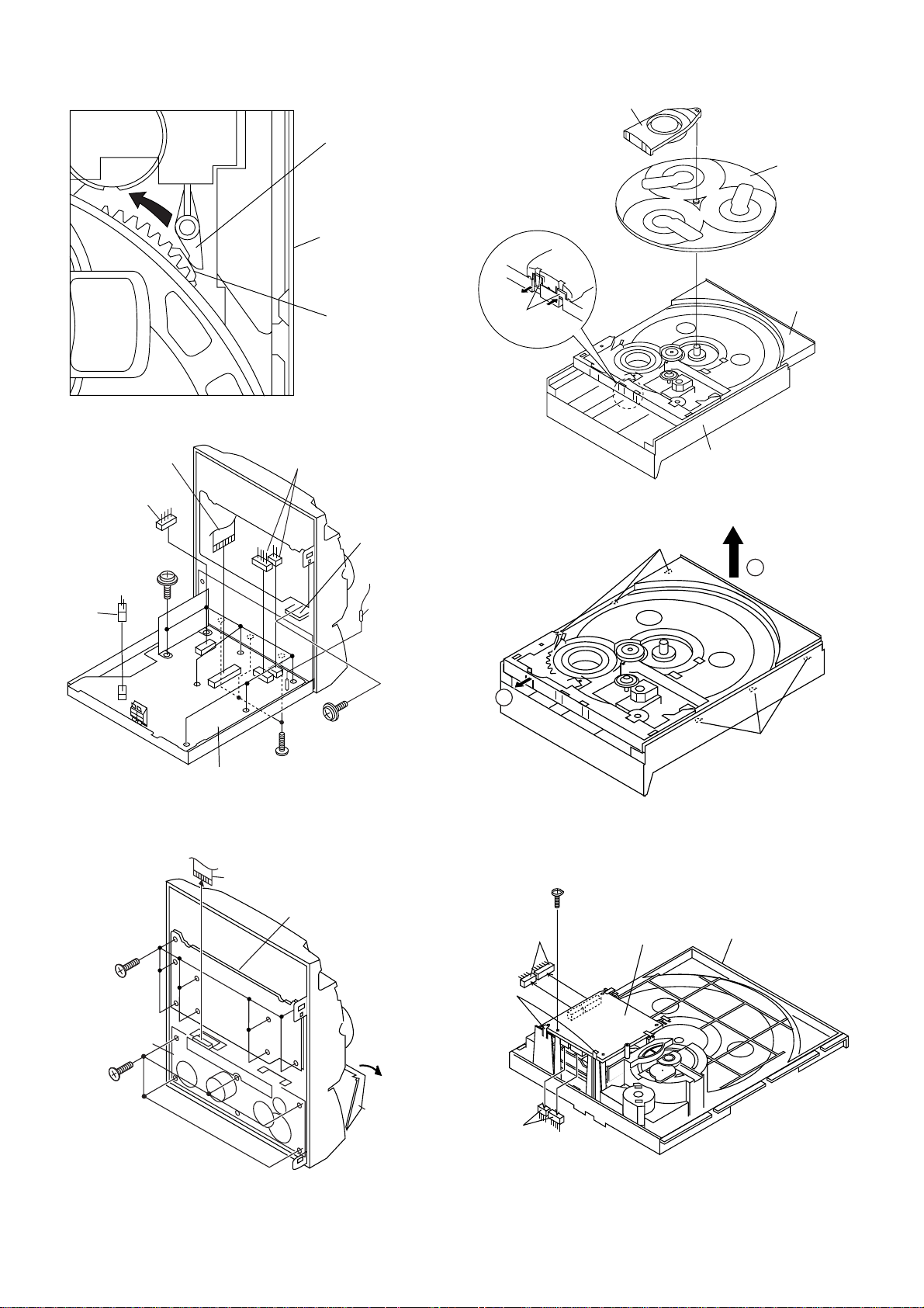
CD-BA1200H
(L3) x2
(L2) x2
(L3) x2
CD Servo
PWB
Slide Chassis
(L1)x1
ø3x8mm
(J2) x1
Clamp Lever
Turntable
CD Player Unit
(Top View)
(E2)x1
(E3)x1
(E2)x1
(E1)x7
ø3x10mm
Figure 10-1
Main PWB
(E2)x2
(F1)x3
ø3x8mm
Cam Gear Rib
Headphones
PWB
(E4)x1
(E1)x1
ø3x10mm
(J1) x2
1
Disc Tray
CD Player Unit
Figure 10-4
(K1) x3
2
(K1) x3
(G1)x9
ø3x10mm
(H1)x5
ø3x10mm
Tape
Mechanism
Figure 10-2
(G2)x1
Figure 10-3
Figure 10-5
Display PWB
Open
Cassette
Holder
Figure 10-6
– 10 –
Page 3
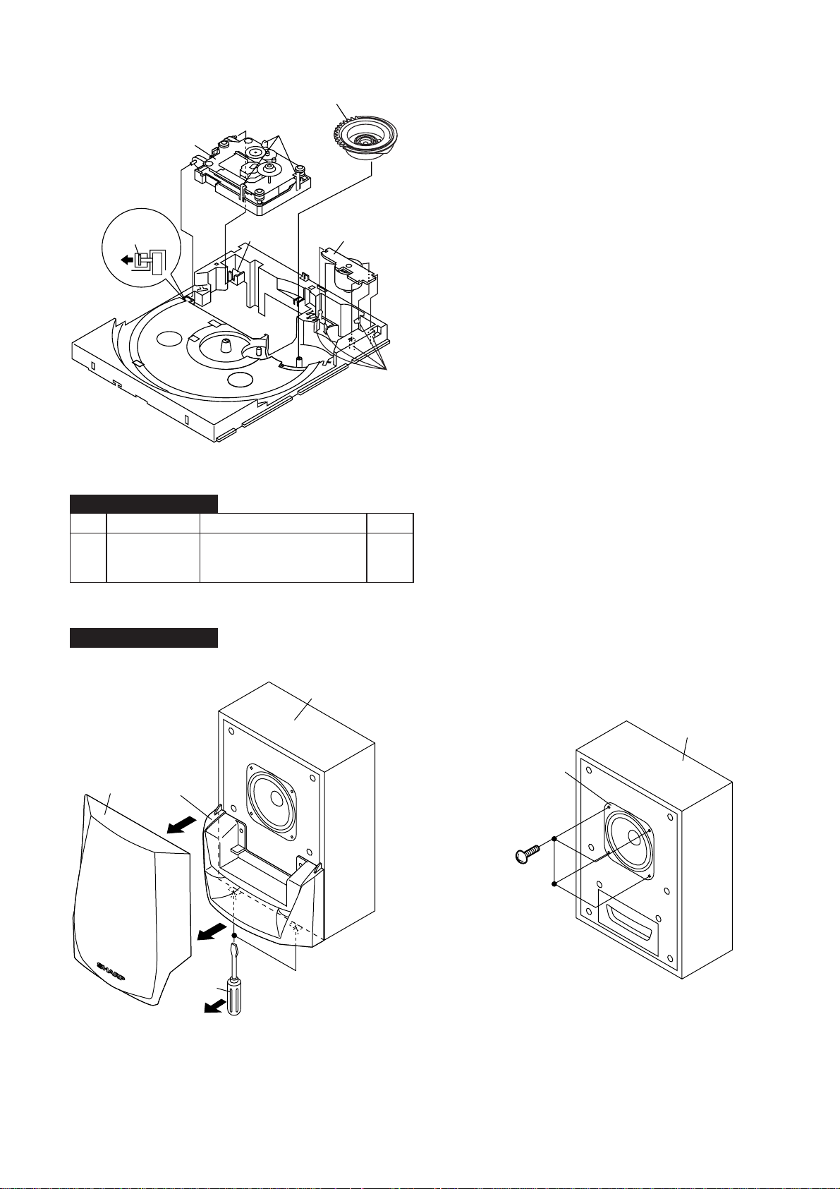
Cam Gear
CD-BA1200H
CD
Mechanism
(M1) x1
Figure 11-1
CP-BA1200H
STEP REMOVAL
1 Speaker 1. Net ..........................(A1) x1 11-2
2. Duct Panel .............. (A2) x1
3. Screw......................(A3) x4 11-3
(M2) x3
(M1) x1
PROCEDURE
Loading
Motor
PWB
(N1) x5
FIGURE
CP-BA1200H
(A1)x1
(A2)x1
Driver
Speaker Box
Speaker Box
Speaker
(A3)x4
ø3.5x13mm
Driver should be
pried away from
Speaker Box.
Direction of handle
Figure 11-2
Figure 11-3
– 11 –
Page 4
CD-BA1200H
REMOVING AND REINSTALLING THE MAIN PARTS
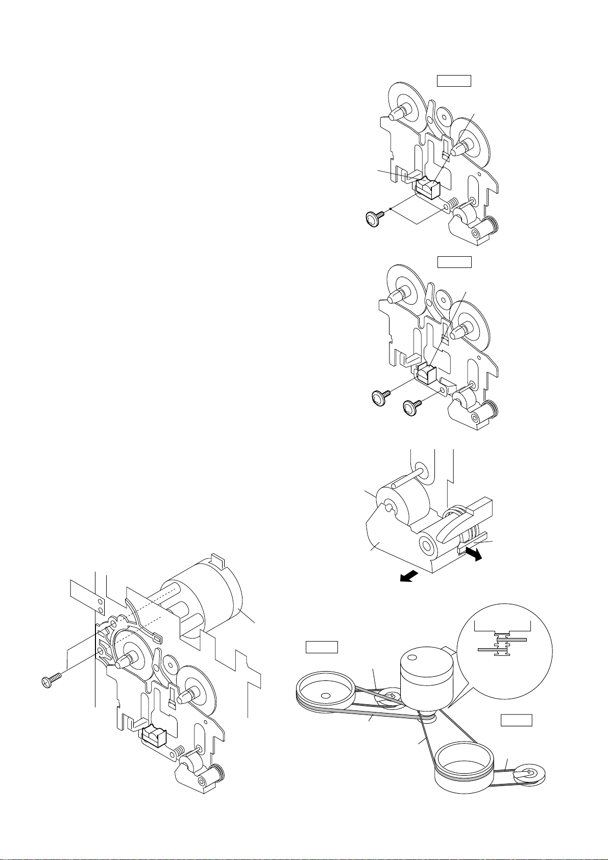
TAPE MECHANISM SECTION
Perform steps 1 to 6 and 8 of the disassembly method to
remove the tape mechanism.
How to remove the record/playback and erase
heads (TAPE 2) (See Fig. 12-1)
1. Carefully remove the record/playback head and erase head
screw (A1) x 2 pcs.
How to remove the playback head (TAPE 1)
(See Fig. 12-2)
1. Carefully remove the playback head screw (B1) x 2 pcs.
How to remove the pinch roller (TAPE 1/2)
(See Fig. 12-3)
1. Carefully bend the pinch roller pawl in the direction of the
arrow <A>, and remove the pinch roller (C1) x1 pc., in the
direction of the arrow <B>.
Note:
When installing the pinch roller, pay attention to the spring
mounting position.
Erase Head
(A1)x2
Ø2 x 9mm
Figure 12-1
TAPE 2
TAPE 1
Playback
Head
Record/Playback
Head
How to remove the belt (TAPE 2) (See Fig. 12-4)
1. Remove the main belt (D1) x 1 pc., from the motor side.
2. Remove the FF/REW belt (D2) x 1 pc.
How to remove the belt (TAPE 1) (See Fig. 12-4)
1. Remove the main belt (E1) x 1 pc., from the motor side.
2. Remove the FF/REW belt (E2) x 1 pc.
How to remove the motor (See Fig. 12-5)
1. Remove the screws (F1) x 2 pcs., to remove the motor.
Motor
TAPE 2
(B1)x1
Ø2x9mm
Pinch Roller
(C1)x1
FF/REW
Belt
(D2)x1
Figure 12-2
Pull
Figure 12-3
(B1)x1
Ø2x5mm
<B>
Motor
Pull
TAPE2
Main Belt
(D1)x1
<A>
Pinch
Roller
Pawl
Motor
TAPE1
Main Belt
(E1)x1
(F1) x2
Ø 2.6 x 5mm
– 12 –
(D1)x1
(E1)x1
Figure 12-4Figure 12-5
TAPE 1
FF/REW
Belt
(E2)x1
Page 5
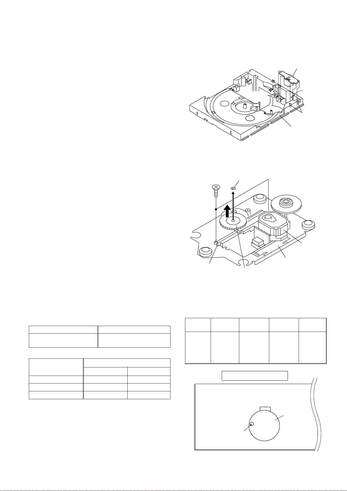
CD MECHANISM SECTION
TAPE MECHANISM
Motor
Variable Resistor
in motor
Perform steps 1, 2, 3, 9 and 12 of the disassembly method to
remove the CD mechanism.
CD-BA1200H
How to remove the loading motor
(See Fig. 13-1)
1. Bend the hooks (A1) x 5 pcs., to remove the loading motor.
How to remove the pickup (See Fig. 13-2)
1. Remove the screws (B1) x 2 pcs., to remove the shaft (B2).
2. Remove the stop washer (B3) x 1 pc., to remove the gear
(B4).
3. Remove the pickup.
Note
After removing the connector for the optical pickup from the
connector, wrap the conductive aluminium foil around the
front end of connector to protect the optical pickup from
electrostatic damage.
(B1) x2
ø2.6 x6mm
Loading Motor
(A1)x1
(A1)x2
(A1)x2
Slide Chassis
Figure 13-1
Stop Washer
(B3) x1
ADJUSTMENT
MECHANISM SECTION
• Driving Force Check
Torque Meter
Play: TW-2111 Tape 1: Over 80 g
• Torque Check
Torque Meter
Tape 1
Play: TW-2111 30 to 80 g.cm 30 to 80 g.cm
Fast forward: TW-2231 — 70 to 180 g.cm
Rewind: TW-2231 — 70 to 180 g.cm
Specified Value
Tape 2: Over 80 g
Specified Value
Tape 2
Pickup
Shaft
(B2) x1
Gear
CD Mechanism
(B4) x1
Figure 13-2
• Tape Speed
Test Tape
Normal MTT-111 Variable 3,000 ± Speaker
speed Resistor in 30 Hz terminal
Adjusting
Point
motor. (Load
Specified
Value
Instrument
Connection
resistance:
6 ohms)
Figure 13-3
– 13 –
Page 6
CD-BA1200H
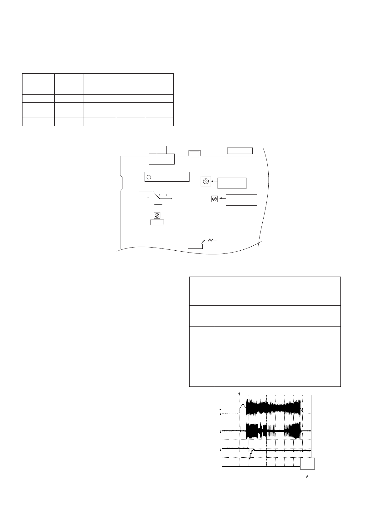
TUNER SECTION
fL: Low-range frequency
fH: High-range frequency
• AM IF/RF
Signal generator: 400 Hz, 30%, AM modulated
Test Stage Frequency
AM IF 450 kHz 1,620 kHz T351 *1
AM Band — 522 kHz (fL): T306 *2
Coverage 1.1 ± 0.1 V
AM Tracking 990 kHz 990 kHz (fL): T303 *1
*1. Input: Antenna Output: TP302
*2. Input: Antenna Output: TP301
Frequency
Display
Setting/
Adjusting
Parts
TP301
R381
Instrument
Connection
SO301
FM ANTENNA
TERMINAL
1
FE301
T351
• FM
Notes:
1: Description of the "FM IF Adjustment" is not carried on this
Manual. It is because the IF coil in the FM front end section
has been best adjusted in the factory so that its further
adjustment is not needed at the field. When replacing the
FM front end assembly, no adjustment is needed either.
2: The parts in the FM front end section are prepared in a
complete unit, so you can't obtain each part individually
CNP302
AM LOOP
ANTENNA
T303
T306
MAIN PWB
AM
TRACKING fL
AM BAND
COVERAGE fL
AM IF
Figure 14-1 ADJUSTMENT POINTS
CD SECTION
• Adjustment
Since this CD system incorporates the following automatic
adjustment functions, readjustment is not needed when
replacing the pickup. Therefore, different PWBs and pickups
can be combined freely.
Each time a disc is changed, these adjustments are
performed automatically. Therefore, playback of each disc
can be performed under optimum conditions.
Items adjusted automatically
(1) Offset adjustment (The offset voltage between the head
amplifier output and the VREF reference voltage is
compensated inside the IC.)
* Focus offset adjustment
* Tracking offset adjustment
(2) Tracking balance adjustment (waveform drawing Fig.
14-2 EFBL)
(3) Gain adjustment (The gain is compensated inside the IC
so that the loop gain at the gain crossover frequency will
be 0dB.)
* Focus gain adjustment
* Tracking gain adjustment
R357
TP302
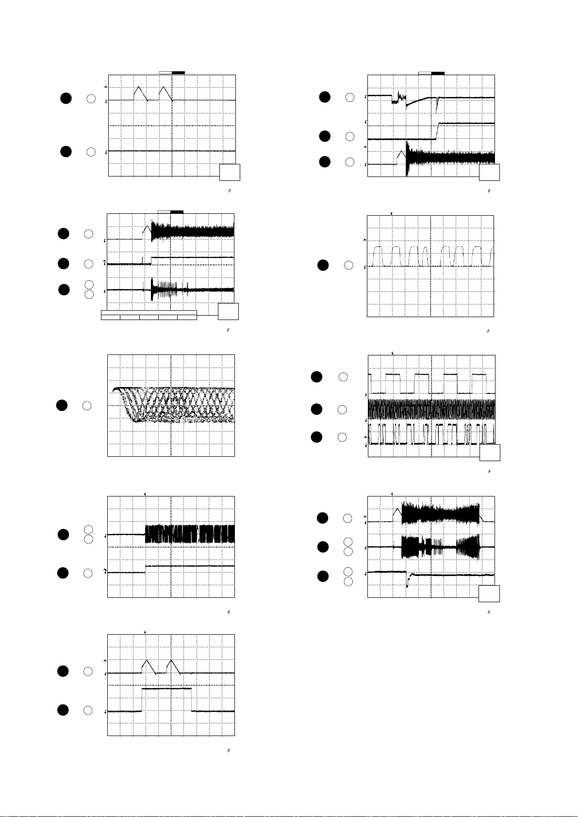
CD ERROR CODE DESCRIPTION
Error State Code
0001 Cannot detect Pickup-in SW
0002 DSP access error
0101 Open/Close SW Low → High not functioning
0103 Open/Close SW High → Low not functioning
0201 Open/Close SW Low → High not functioning
0203 Open/Close SW High → Low not functioning
0302 Pickup-in SW is not detected
0306 During Disc 1 search, Open/Close SW or Clamp SW
0307 Clamp SW Low → High not functioning
0308 Clamp SW High → Low not functioning
[Servo System Error]
[Error during close operation]
[Error during open operation]
[Error during skip operation]
or Disc SW do not change to low.
T
T
1
3
Stopped
FDO
TE
CH1=500mV
DC 10:1
CH2=200mV
DC 10:1
CH3=1V
DC 10:1
1999/04/05 20:26:47
500ms/div
(500ms/div)
NORM:20kS/s
– 14 –
EFBL
2
Smoothing : ON CH1 : 0.000V
BW : FULL
CH2 : 0.000V
CH3 : 0.00V
CH4 : 0.00V
Figure 14-2
=Record Length=
Main : 100K
Zoom : 2k
CH2
v/DIV
200mV
=Trigger==Filter= =Offset=
Mode : SINGLE
Type : EDGE CH1
Delay : 0.0ns
Hold off : 0.2us
Page 7
NOTES ON SCHEMATIC DIAGRAM
• Resistor:
To differentiate the units of resistors, such symbol as K and
M are used: the symbol K means 1000 ohm and the symbol
M means 1000 kohm and the resistor without any symbol is
ohm-type resistor. Besides, the one with “Fusible” is a fuse
type.
• Capacitor:
To indicate the unit of capacitor, a symbol P is used: this
symbol P means micro-micro-farad and the unit of the
capacitor without such a symbol is microfarad. As to
electrolytic capacitor, the expression “capacitance/withstand
voltage” is used.
(CH), (TH), (RH), (UJ): Temperature compensation
(ML): Mylar type
(P.P.): Polypropylene type
• Schematic diagram and Wiring Side of P.W.Board for this
model are subject to change for improvement without prior
notice.
CD-BA1200H
• The indicated voltage in each section is the one measured
by Digital Multimeter between such a section and the chassis with no signal given.
1. In the tuner section,
( ) indicates AM
< > indicates FM stereo
2. In the main section, a tape is being played back.
3. In the deck section, a tape is being played back.
( ) indicates the record state.
4. In the power section, a tape is being played back.
5. In the CD section, the CD is stopped.
• Parts marked with “ ” ( ) are important for
maintaining the safety of the set. Be sure to replace these
parts with specified ones for maintaining the safety and
performance of the set.
REF. NO DESCRIPTION POSITION POSITION
SW1 OPEN/CLOSE ON—OFF
SW2 CLAMP ON—OFF
SW3 DISC NUMBER ON—OFF
SW4 PICKUP IN ON—OFF
SW701 ON/STAND-BY ON—OFF
SW702 CLOCK ON—OFF
SW703 TIMER/SLEEP ON—OFF
SW709 DISC SKIP ON—OFF
SW710 OPEN/CLOSE ON—OFF
SW711 EQUALIZER/X-BASS/DEMO ON—OFF
SW712 VOLUME UP ON—OFF
SW713 VOLUME DOWN ON—OFF
REF. NO DESCRIPTION
SW714 CD ON—OFF
SW715 TAPE ON—OFF
SW716 TUNING /TIME DOWN ON—OFF
SW717 MEMORY/SET ON—OFF
SW718 REWIND ON—OFF
SW719 FAST FORWARD ON—OFF
SW720 PLAY/REPEAT ON—OFF
SW721 STOP ON— OFF
SW723 REC/PAUSE ON—OFF
SW724 TUNING/TIME UP ON—OFF
SW725 TUNER (BAND) ON—OFF
FRONT
VIEW
FRONT
FRONT
VIEW
VIEW
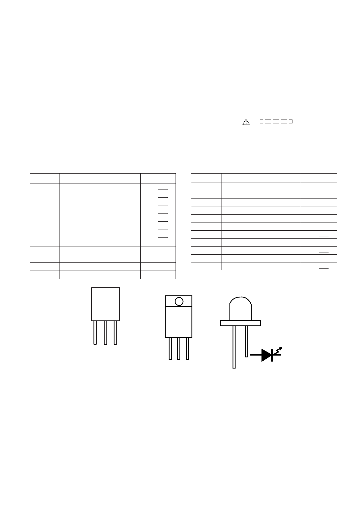
E C B
(S) (G) (D)
(1) (2) (3)
BCE
2SC1845 F
2SC3331
2SC380 O
KTA1266 GR
KTA1271 Y
KTA1273 Y
KTC3203 Y
KRC102 M
KRC104 M
KRC107 M
KTC2026
4204SRT7
Figure 15 TYPES OF TRANSISTOR AND LED
– 15 –
Page 8
CD-BA1200H
5
1
3
4
4
3
1
1
2
IC2 24
IC2 23
IC2 24
IC2 72
IC1 18 ,
IC2 16
IC1 27
IC1 18 ,
IC2 16
IC2 72
IC2 24
Stopped
CH1=500mV
DC 10:1
T
FDO
1
TDO
3
Smoothing : ON CH1 : 0.000V
BW : FULL
1
T
2
3
Smoothing : ON CH1 : 0.000V
BW : FULL
2
T
1
Smoothing : ON CH1 : 0.0V
BW : FULL
T
2
CH2 : 0.0V
CH3 : 0.000V
CH4 : 0.00V
Stopped
CH1=500mV
DC 10:1
FDO
DRF
TE
CH Position To
-3div -1div 0div +1div +3div
CH2 : 0.0V
CH3 : 0.00V
CH4 : 0.00V
Stopped
CH1=10V
DC 10:1
TE
DRF
=Filter= =Offset=
CH2 : 0.00V
CH3 : 0.00V
CH4 : 0.00V
Stopped
CH1=200mV
DC 10:1
FDO
CH2=10V
DC 10:1
T
CH2=1V
DC 10:1
T
CH2=500mV
DC 10:1
CH3=500mV
DC 10:1
=Record Length=
Main : 100K
Zoom : 2K
CH3=1V
DC 10:1
=Record Length=
Main : 100K
Zoom : 2K
=Record Length=
Main : 100K
Zoom : 2K
WAVEFORMS OF CD CIRCUIT
500ms/div
(500ms/div)
NORM:20kS/s
IC2 1
7
IC2 2
8
IC2 24
10
11
12
1
9
1
4
13
IC2 37
IC2 57
IC2 58
IC2 59
IC2 24
IC1 18 ,
IC2 16
IC1 13 ,
IC2 22
CH1
v/DIV
500mV
=Trigger==Filter= =Offset=
Mode : AUTO
Type : EDGE CH1
Delay : 0.0ns
Hold off : 0.2us
500ms/div
(500ms/div)
NORM:20kS/s
CH2
Position
0.20div
=Trigger==Filter= =Offset=
Mode : AUTO
Type : EDGE CH1
Delay : 0.0ns
Hold off : 0.2us
Vp-p=1.0V~1.3V
0.5mV/div,0.5µsec/div
100ms/div
(100ms/div)
NORM:100kS/s
=Trigger=
Mode : NORMAL
Type : EDGE CH1
Delay : 2.924ms
Hold off : 0.2us
1999/04/07 09:51:15
500ms/div
(500ms/div)
NORM:20kS/s
Stopped
PDO1
3
4
PDO2
T
FDO
1
Smoothing : ON CH1 : 0.000V
BW : FULL
Stopped
T
1
DOUT
Smoothing : ON CH1 : 0.00V
BW : FULL
Stopped
1
LRSY
2
DATACK
T
3
DATA
Smoothing : ON CH1 : 0.00V
BW : FULL
Stopped
T
FDO
1
TE
3
EFBL
2
Smoothing : ON CH1 : 0.000V
BW : FULL
CH1=500mV
DC 10:1
CH1=2V
DC 10:1
CH1=2V
DC 10:1
CH1=500mV
DC 10:1
CH2 : 0.0V
CH3 : 0.00V
CH4 : 0.00V
T
CH2 : 0.00V
CH3 : 0.00V
CH4 : 0.00V
T
CH2=2V
DC 10:1
CH2 : 0.00V
CH3 : 0.00V
CH4 : 0.00V
T
CH2=200mV
DC 10:1
CH2 : 0.000V
CH3 : 0.00V
CH4 : 0.00V
CH3=1V
DC 10:1
=Record Length=
Main : 100K
Zoom : 2K
=Record Length=
Main : 1K
Zoom : 100
CH3=2V
DC 10:1
=Record Length=
Main : 5K
Zoom : 100
CH3=1V
DC 10:1
=Record Length=
Main : 100K
Zoom : 2k
1999/04/05 17:33:17
CH4=1V
500ms/div
(500ms/div)
DC 10:1
NORM:20kS/s
=Trigger==Filter= =Offset=
Mode : AUTO
Type : EDGE CH2
Delay : 0.0ns
Hold off : 0.2us
1999/04/07 09:25:28
500ns/div
(500ns/div)
NORM:200MS/s
=Trigger==Filter= =Offset=
Mode : NORMAL
Type : EDGE CH1
Delay : 2.887ms
Hold off : 0.2us
1999/04/05 20:50:17
NORM:100kS/s
=Trigger==Filter= =Offset=
Mode : AUTO
Type : EDGE CH3
Delay : 0.0ns
Hold off : 0.2us
1999/04/05 20:26:47
500ms/div
(500ms/div)
NORM:20kS/s
=Trigger==Filter= =Offset=
Mode : SINGLE
Type : EDGE CH1
Delay : 0.0ns
Hold off : 0.2us
5us/div
(5us/div)
CH1
v/DIV
500mV
CH3
v/DIV
2 V
CH2
v/DIV
200mV
SPDO
IC2 25
6
1
=Filter= =Offset=
Smoothing : ON CH1 : 0.000V
BW : FULL
CH2 : 0.000V
CH3 : 0.00V
CH4 : 0.00V
=Record Length=
Main : 100K
Zoom : 2K
=Trigger=
Mode : NORMAL
Type : EDGE CH2
Delay : 2.924ms
Hold off : 0.2us
– 16 –
Page 9

TO MAIN SECTION
(TO IC601)
TO DISPLAY SECTION
SW1
OPEN/
CLOSE
12
CD-BA1200H
SW2
SW3
CLAMP
DISC
NUMBER
M
+
5
3
4
6
M3
T/T
UP/DOWN
MOTOR
-
BI4
XL1
16.9344MHz
12
R-CH
L-CH
AGND
DGND
+5V(+B4)
2
1
5
3
4
CNP11
CDINT
CE
DO
DRF
WRQ
217
DI
5
6
43
CLK
89
CD RES
CLAMP SW
GND
10
CNP12
12
56
3
4
3
4
56
CNS4
CNP4
Q2
CONT4
RFENV
FE
30
CONT3
CONT5
TE
CONT2
SLDO
SPDO
FDO
TDO
74
64
40
19
13
3
33
26
25
24
23
75
76
65
CE
CL
66
DI
67
DO
68
INT
69
WRQ
70
RES
71
72
DEF
XOUT
52
XIN
51
VDD5V
73
CONT7
CONT6
VVDD
ADAVDD
VDD
5
183644 49 50 7 14 15 16
47 48 32 31
45 46
LVSS
LCHO
IC2
LC78641E
SERVO/SIGNAL
CONTROL
LVDD
RVDD
XVDD
RVSS
RCHO
HFL
CONSTANT
VOLTAGR
+3.3V
PICKUP UNIT
+5V
+3.3V
1
2 1725 4142 3839
22
18 19 20
Q1
17
HFL
30
IC1
LA9235M
23
SERVO AMP.
11
9
TIN2
TIN1
FIN2
FIN1
12
34
+5V
21
FE
TE
7
FE-
TE-
PD
LDD
RFEV
LASER
DRIVER
Q3
+3.3V
8
M1
SPINDLE
MOTOR
FOCUS COIL
TRACKING COIL
M2
SLED
MOTOR
VCC1
18
VCC4
+5V
40
24
23
28
VCC2
VCC3
FOCUS/TRACKING/
SPIN/SLED DRIVER
45671516 26 27
M
M
IC3
M63001FP
35
29
22
21
14
8
SW4
PICKUP IN
Figure 17 BLOCK DIAGRAM (1/3)
– 17 –
Page 10

CD-BA1200H
Q
FM
ANTENNA
TAPE
MOTOR
SOLENOID
T2 PLAY
T1 PLAY
R.PLAY
F.PLAY
TAPE1
PBHEAD
TAPE2
RECPBHEAD
AM LOOP
ANTANNA
L341
BALUN
MOTOR
DRIVER
Q706
M
Q704
Q705
IC701
54PIN
IC701
53PIN
IC701
56PIN
IC701
55PIN
FROMCDSECTION
CNP11
L-CH
R-CH
REC
P.B.
L-CH
R-CH
ACBIAS
ERASE
HEAD
8
AM TRACKING
T303
+2B
+2B
SWITCHING
Q104~
Q107
TA7358AP
FM FRONT END
2
6
CNS601
1
2
3
4
5
POP
REDUCE
Q108
Q109
SWITCHING
Q114
L104
BIAS
OSC
FE301
3
7
FMOSC
T306
PLAYBACKANDRECORD
1
L(T1)
R(T1)
24
L(T2)
2
R(T2)
23
LNF
3
RNF
22
6
LREC
9
RREC
16
14
REF
12
1
5
4
AM BAND
COVERAGE
IC101
AN7345K
/PLAYBACKAMP.
P.B
T1/T2
REC
NOR/
15
12
SWITCHING
Q103
Q101
SWITCHING
CF301
H/N
T1/T2HIGH
19
Q102
FM +B
+B3
13
L
4
R
21
5
20
RECRL
7
18
LNF
8
RNF
17
ALC
10
Q112
L103
SWITCHING
Q301
VT
SWITCHING
Q360
+B3
PB
BIAS
Q113
20
FM
CF302
1
AM IF
21
AM
MIX
IC303
LA1832S
FM IF DET./FM MPX./AM IF
AMRFIN
FMAFC
15
16
IC302
LC72131
PLL(TUNER)
FM/AM
7
L
TAPE
R
TUNER
L
242122
9
X352
4.5MHZ
OSC
23
AMOSCIN
22
R
L
CD
R
CF352T351
4
5
GND
FM/AM
CE
3
OUT
18
9
CL
DI
4
5
2
1
AM IF
7
STEREO
11
MO/ST
10
9
16
10
15
1
14
IC601
LC75341
AUDIOPROCESSOR
12
13
17
8
7
CF351
FMFM+B
DET
16
6
18
8
DO
VCO
17
+B3
23
3
X351
456kHz
13
17
MO/ST
FM/AMMPXIN
12
MUTING
L
14
R
15
CE
CL
Q110
Q111
+B3
1
DI
2
24
R
21
4
Q601
Q602
L
SYSTEM
MUTE
REC/PLAY
T1/T2
BAIS
Figure 18 BLOCK DIAGRAM (2/3)
– 18 –
Page 11

CD-BA1200H
+B3
Q701
1
SP.DET.
FL701
DISPLAY
2
10 111315 16 19 20 22 261417 182127
3
5556
575859
71
78
VLOAD
79
80
91
92
MICROCOMPUTER
99
100
VDD
145
9
6
10
7
+B6
Q901
Q902
RESET
Q707
IC701
IX0337AW
SYSTEM
RESET
11
12 13 15 16
XL701
4.1943 MHz
+B6
30
+B6
VDD
VDD
17
RESET IC
IC704
3
KIA7042PA
31
CEDICL
20
21222324
2
32 33
SYS.STOP
AVDD
1
404142434445464748495051525354
39
38
37
36
35
+B6
34
33
31
DO
+B6
KEY
SW701-SW703
SW709-SW721
SW723-SW725
TO CD
SECTION
JK901
HEADPHONES
+B2
SO901
SPEAKER
IC901
L
2
LA4282
POWER
R
Q601
Q602
L
SYSTEM
MUTE
R
5
AMP.
Vcc
10
Q904
R-OUT
7
L-OUT
11
9
4
F901
T2.5A L 250V
PT801
MAIN POWER
TRANSFORMER
D907 910
Q903
IC902
KIA7810AP
VOLTAGE
REGULATOR
IC904
KIA7810AP
VOLTAGE
REGULATOR
+5V
5W
+B5
UNSWITCH
5V
+B1
D806
VOLTAGE REGULATOR
D911 D914
IC903
AN7805
CONSTANT
F902
T1.6A L 250V
Q803
D802~805
T.F.
PT802
SUB POWER
TRANSFORMER
REC/PLAY
T1/T2
BAIS
VF1
VF2
+B2
+B3
+B4
M10V
A10V
+5V
+B6
TERMINAL
RL801
L801
LINE
FILTER
SO902
AC INPUT
AC POWER
SUPPLY CORD
AC 230V,50Hz
Figure 19 BLOCK DIAGRAM (3/3)
– 19 –
Page 12

CD-BA1200H
B
P
A
D
F
P
S
3
0
8
2
9
7
A
Vcc
7
7
Vref
6
B
6
E
5
5
A
4
4
B
3
3
F
2
2
C
1
1
C
D
CD SERVO PWB-B
CNS1A
CNS1B
7
7
6
6
R51 68K
5
5
R52 68K
4
4
R53 68K
3
3
R54 68K
2
2
1
1
CNP1
R56
68K
+B
C51
C53
47/10
0.001
Q3
KTA1266GR
LASER DRIVER
0.1
C41
100/10
C23
0.047
C24
2.2/50
C22
100P
R15
10K
R43
220K
8
R12
680
R79
R1
1.5M
68
C
C21
0.1
0.0
R11
12K
R1
R80
1M
1.2
C27
0.1
C26
0.047
PH(R
A
C2
C28
0.1
47/10
2
R44
1K
EFBL
+B
R50
47
TIN1
FIN1
FIN2
TIN2
R55
68K
FIN1
1
REF
FIN2
2
REF
TIN1
C55
C54
0.01
47/10
C7
10/16
C8
0.1
+B
R25
10K
R47
3.3
TIN2
C6
100/10
REF1
VREF
LDD
GND
LDON
AGON
EFBL
TEST0
TES1
3
REF
4
REF
5
6
7
8
9
10
11
12
13
14
15
REF
APC
ODRV
AGCON
IC1
LA9235M
SERVO AMP.
REF
REF
LPF
REF
C11
0.47/6.3
VCC
30
ODRV
REF
AGCON
REF
PH
DH
ODRV
PH/BH
REF
LPF
REF
LPF
REF
REF
REF
C12
0.1
RFSW
29
R42
120K
RF-
28
RF
27
NC
26
PH
25
BH
24
23
RFEV
22
FE-
21
FE
20
TE-
19
TE
18
HFL
17
16
TEST
100K
10K
C18
R7
3P
6.8K
(CH)
R6
R5
27K
39K
5
C13
0.01
C14
0.33
R3
R4
4
C19
C17
0.0047
DS1SS133
100/10
C20
0.1
C82
0.022
D93
C25
R10
27K
R8
330
C42
68P
E
TR+
FO+
FO-
F
TR-
ACTUATOR
PICKUP UNIT
G
CD MOTOR PWB-C
M1
SPINDLE
MOTOR
M2
SLED
MOTOR
SW4
PICKUP IN
H
13
TDO
LD_M+
LD_MVCC4
LOADING M+
LOADING M-
GND
VCC3
SP-
SP+
SPDO
SPO
VCC2(SPN)
C47
100/16
+B
+B
C52
0.01
+B
TDO
C50
100/16
FDO
0.022
C46
GND
SLDO
VCC1
STANDBY
MUTE
TO
FD
FO
FO+
FO-
TR+
TR-
SL-
SL+
Vref
C49
TRTR+
FO+
FOGND
+
M
+
M
-
VR
LD
CNP3A
1
1
2
2
3
3
4
4
5
5
6
6
PD
7
7
CNS2B
CNS3B
6
6
5
5
4
4
3
3
2
1
1
1
2
3
4
5
6
7
88
6
5
4
3
22
1
CNS2A
CNS3A
TR-
1
TR+
2
FO+
3
FO-
4
GND
5
PD
6
VR
7
LD
88
CNP2
+B
R48
6.8K
SP-
6
SP+
5
SL+
4
SL-
3
PUIN
2
GND(D)
1
CNP3
+B
100/16
-
1
2
3
4
5
6
7
8
9
10
11
12
13
14
15
16
17
18
19
20
21
-
+
+
-
+
-
+
IC3
M63001FP
FOCUS/TRACKING/
-
-
+
+
+
-
SPIN/SLED DRIVER
+B
+
42
-
+
-
41
+
40
-
39
38
37
36
35
34
33
32
31
30
29
28
27
26
-
-
25
+
+
+
24
-
+
23
-
+
-
22
FDO
• NOTES ON SCHEMATIC DIAGRAM can be found on page 15.
1
23456
Figure 20 SCHEMATIC DIAGRAM (1/10)
– 20 –
Page 13

CD-BA1200H
+B
42
41
40
39
38
37
36
35
34
33
32
31
30
29
28
27
26
25
24
23
22
C19
C17
0.0047
0.022
DS1SS133
13
LD_M+
LD_MVCC4
LOADING M+
LOADING M-
GND
VCC3
SPSP+
SPDO
SPO
VCC2(SPN)
100/10
R10
27K
C20
0.1
C82
D93
R8
330
C42
68P
C47
100/16
C25
0.1
C41
100/10
+B
+B
C23
0.047
C24
2.2/50
C22
100P
R15
10K
R43
220K
CD SIGNAL
R94
10K
R95
DEFECT
EFMO
JITER
DEFECT
CONTROL
A/DSW
R39
470
+B
80
D/A
SLDO
+B
Q2
KRC102M
10K
79 78
FRAME SYNC
DEFECT,PROTECT
EFM DECODE
CLV
CONTROL
SW
AUTO
ADJUST
LASER
27
28
FG(D_Vref)
+B
R22
470
D22
DS1SS133
FSEQ
1
8
7
R12
680
PD01
R13
680
C81
0.022
PCKIST
R14
1.2K
SLCIST
EFMIN
0.1
PH(RFENV)
ADAVDD
C29
0.1
ADAVSS
PHREF
BHREF
R44
1K
R35
TDO
FDO
PD02
VVSS
VVDD
SLCO
JITTV
JITTC
VREF
TBLO
1K
HFL
TDO
FDO
1
2
3
PLL
VCEC
4
5
FR
6
7
8
SLICE
LEVEL
9
CONTROL
10
11
12
BH
13
14
FE
15
TE
16
17
18
+
-
19
20
21
S/H
22
23
24
26
25
SPDO
1
R38
270
SLDO
SPDO
6
R21
470
D21
DS1SS133
R79
1.5M
C21
0.1
R11
12K
R80
1M
C27
C26
0.047
C28
47/10
2
EFBL
DISC_NO
V/vP
77
76
GENERAL
PROCESSEROR
CONT2
CONT1
30
29
R40 1.2K
32
O/C
R67 1K
R68 1K
CONT7
CONT6
75
SERVO
GENERAL
CONT3
31
R45 1.2K
C71 100P
C72 0.01
C73 100P
C74 100P
C75 100P
C76 100P
C77 100P
C78 100P
C80
VSS
0.1
VDD5V
74
CONT5
CONT4
33
32
R17 1K
R46 1K
+B
+B
34
+B
DEF
RES
WRQ
73
72
70
71
IC2
LC78641E
SERVO/SIGNAL
CONTROL
INTERPOLATION
MUTE
ERROR
AUDIO
CORRECT
OUT
FSX
35
37
36
38
VDD
C2F
PCK
DOUT
C31
100/10
R16
10K
INT
69 68
SERIAL
EXTERNAL
ATTENUATION
DEEMPHASIS
DIGITAL
1BIT
39
C30
0.1
COMMAND
INTERFACE
OUT
AUDIO IN
FILTER
DAC
EFLG
40
67
SUBCODE
DECODE
CRC
TEST
CLDIDO
66
CLOCK
9
R71 1K
R72 1K
R73 1K
R74 1K
R75 1K
R76 1K
R77 1K
R78 1K
CE
65
GENERATOR
LPF
+B
64
63
62
61
60
59
58
57
56
55
54
53
52
51
50
49
48
47
46
45
44
43
42
41
L62
2.2µH
SBCK
PW
SBSY
SFSY
16M
DATA
DATACK
LRSY
ASDFIN
ASDACK
ASLRCK
XVSS
XOUT
XIN
XVDD
RVDD
RCHO
RVSS
LVSS
LCHO
LVDD
MUTER
MUTEL
EMPH
L61
0.82µH
16.9344MHz
R20
220
+B
+B
C38
10/16
C39
+B
10/16
47
R19
+B
CONSTANT VOLTAGE
Q1
KTC3203Y
+B
ZD61
DZ3.9BSB
C34
0.022
R82
2.2K
R81
2.2K
100/10
XL1
C44
0.1
C45
12
11
10
330/6.3
C56
C64
C40
0.0015
C43
0.0015
R58
0.47/6.3
DRF
RES
WRQ
INT
DO
DI
CL
CE
+B
R-CH
1
AGND
+B
DGND
INT
WRQ
DRF
CE
DO
DI
CL
RES
L-CH
+B
3
4
5
2
P22 1 - B
CNS601
3
TO MAIN PWB
4
+5V
5
CNP11
CDINT
1
WRQ
2
DRF
3
CE
4
5
6
7
8
9
10
CNP12
CNS4
1
1
2
2
3
4
5665
DO
DI
CLK
CD RES
CLAMP SW
GND
BI4
1
2
3
4
6
P25 12 - B
CNS702
TO DISPLAY PWB
SW1
OPEN/
CLOSE
SW2
CLAMP
SW3
DISC
NUMBER
+
M3
M
T/T
UP/DOWN
LOADING
10K
R84
10K
R83
C83
0.022
+B
220
+B
O/C
GND(D)
DISC_NO
M+
M-
CNP4
CD LOADING
MOTOR PWB-E
3
• The numbers 1 to 13 are waveform numbers shown in page 16.
7
8 9 10 11 12
Figure 21 SCHEMATIC DIAGRAM (2/10)
– 21 –
Page 14

CD-BA1200H
V
M
C138 220/10
Q
S
A
1
1
2
2
P21 12 - D
CNP11
TO CD SERVO
PWB
B
C
3
4
5
CNS601
P26 1 - G
3
4
5
17
4
18
12
TO POWER PWB
19
BI601
R-CH
A_GND
L-CH
CD_GND
+5v +B
L
GND
R
+5V
GND
D902
1SS133
(A_GND)
(CD_GND)
IC601
LC75341
AUDIO PROCESSOR
DI
1
CE
2
VSS
C607 10/50
C609
0.1(ML)
R615
3.9K
C611
R617
3.3K
0.1(ML)
C613 0.0027
C617 1/50
C629 1/50
C625
1/50
R609
R601
330
+B
+B
R602
330
R604
1.8K
R603
1.8K
10K
SYSTEM MUTE
Q601
2SC3331
Q602
2SC3331
SYSTEM MUTE
R610
10K
C601
0.001
C602
0.001
R607
2.2K
R608
2.2K
C603
22/25
R625
22K
C633
0.001
3
LOUT
4
LBASS
5
LTRE
6
LIN
7
LSEL0
8
L4
9
C623
1/50
L3
10
L2
11
L1
12
C627
1/50
CCB
INTERFACE
-
+
-
+
+
-
+
AUX
DECK
TUN
CD
CLK
24
23
VDD
+
VREF
+
-
-
-
+
22
ROUT
21
-
+
RBASS
20
RTRE
19
RIN
18
RSEL0
17
R4
16
R3
15
R2
14
R1
13
C610
0.1(ML)
C612
0.1(ML)
C614
0.0027
C618
1/50
C624
1/50
C626
1/50
C630
1/50
C628
1/50
C606
22/50
C608
10/50
+B
C604
100/25
C605
0.022
R616
3.9K
R618
3.3K
D
E
F
G
R-CH
L-CH
PLAYBACK HEAD
ERASE
HEAD
R-CH
L-CH
TAPE1
PLAYBACK
HEAD
TAPE2
RECORD/
FM SIGNAL
PLAYBACK SIGNAL
RECORD SIGNAL
CD SIGNAL
1
1
1
2
2
2
3
3
3
CNS101A
CNS101B
1
1
1
2
2
2
3
3
3
4
4
4
5
5
5
6
6
6
7
7
7
CNS102A
CNS102B
TAPE1_R
A_GND
TAPE1_L
M_GND
ERASE
TAPE2_R2
A_GND
TAPE2_R1
TAPE2_L1
TAPE2_L2
LUG1
MECHA BASE GND
1
2
3
CNP101
1
2
3
4
5
6
7
CNP102
C105
180P
C103
560P
C104
180P
C102
560P
SWITCHING
Q104
2SC1845F
Q106
2SC1845F
SWITCHING
SWITCHING
Q107
2SC1845F
Q105
2SC1845F
SWITCHING
C101
0.047
R101
10K
Q101
KTA1266 GR
SWITCHING
R106
2.2K
R108
3.3K
R109
3.3K
R107
2.2K
R102
10K
R103
4.7K
R111
4.7K
R113
47K
SWITCHING
2
1
SWITCHING
R137
15K
R104
1K
R105
1K
Q108
2SC3331
R110 47K
R112 4.7K
Q109
2SC3331
Q102
KRC104 M
3
1
32
Q103
KRC104 M
SWITCHING
C107
560P
SWITCHING
C106
560P
+B
R157
100
C108
100/16
IC101:PLAYBACK AND RECORD/
C116
100/25
C118
0.033
L102
R114
2.2mH
1K
C114
C112
330P
330P
24
23
R
L
C113
C115
330P
330P
R115
L101
1K
2.2mH
C119
0.033
C117
100/25
R117
56
R142
220K
MUTING
Q110
2SC3331
0V
0.7V
R140
10K
R134
100
C132
0.0033
R132
1.5K
C126
270P
C130
0.022
C128
22/25
16
17
56K
Hich=CHROME
+
56K
-
9
8
C129
22/25
R133
100
C127 270P
C131
0.022
C133 0.0033
R131 1.5K
R130
R126 68K
R128
IC101
AN7345K
C139
3.3/50
R127
0V
3.9K
6.8K
18
7
6.8K
R129 3.9K
PLAYBACK AMP.
R124
R116
33K
56
R122
C122
5.6K
1/50
R118
R120
100K
3.9K
22
112K
+ +
Hich=T1
+
112K
-
321
R121
R119
3.9K
100K
R138
15K
C146
0.001
C120
560P
20
21
19
4
R123
5.6K
C121
560P
C123
1/50
5
C137
0.022
R125
33K
6
R136
10K
C134
47/25
15
Nor/CrO2
ALC
10
C135
47/25
R135
10K
REC_R
2
R141
10K
0.7
C136 22/25
14
RIPPLE
ALC
11
H
• NOTES ON SCHEMATIC DIAGRAM can be found on page 15.
1
23456
Figure 22 SCHEMATIC DIAGRAM (3/10)
– 22 –
Page 15

L
S
MAIN PWB-A1(1/3)
K
6
8K
5
CD-BA1200H
+B
R140
10K
C132
0.0033
16
56K
56K
9
C135
47/25
C133 0.0033
R616
3.9K
R136
C134
47/25
15
ALC
10
R135
10K
C604
100/25
C605
0.022
R618
3.3K
R141
10K
0.7V
10K
C136 22/25
14
RIPPLE
Nor/CrO2
ALC
11
REC_R
MUTING
Q111
2SC3331
0V
0V
R139
180
C138 220/10
13
Vcc
GND
12
R143
220K
LK
24
23
DD
EF
UT
S
RE
IN
0
R4
R3
R2
R1
3.9K
.
18
1
K
7
6.8
R129 3.9K
22
21
20
19
18
17
16
C624
15
1/50
C626
14
1/50
13
0V
0V
C126
270P
C127 270P
C610
0.1(ML)
C612
0.1(ML)
C614
0.0027
C618
1/50
C630
1/50
C628
1/50
R142
220K
MUTING
Q110
2SC3331
0.7V
R134
R132
1.5K
C130
C128
22/25
17
+
Hich=CHROME
+
-
8
C129
22/25
R133
C131
R131 1.5K
C606
22/50
C608
10/50
100
0.022
100
0.022
REC_L
+B
C145
470P
+B
+B
+B
Q112
KTA1266 GR
SWITCHING
L103
100µH
R146
82
(1/2W)
R147
47K
R148
22K
C148
0.047
(D_GND)
GND
10
GND
(A_GND)
+B
+B
11.7V
0V
C140
0.0082
(PP)
+B
C141
0.039
(ML)
11.6V
R144
47K
R145
4.7K
11.6V
Q114
KTC3203 Y
BIAS OSC
0V
0V
2
L104
330µH
1
Q113
KRC104 M
BIAS
0V
0V
R149
4.7
+B
+B
+B
3
0V
+B
VF2
M_10V
P26 1 - G
TO POWER PWB
+B
(D_GND)
GND
SW_5V
POWER
C142
47/25
+B
A_10V
-VP
VF1
51514 16 21 10 12 22 11 13 20
+B
+B
UN_SW_5V
AC_RLY_CONT
+B
AC_RLY_CONT
(M_GND)
GND
UN_SW 5V
T_BIAS
T_T1/T2
REC/PLAY
M_GND
M_10V
SMUTE
D_GND
SW_5V
POWER
A_10V
CE
DI
CLK
TUN_R
TUN_L
DO
SM
SM
CE
DO
DI
CLK
VF1
-VP
VF2
4
5
7
6
9
2
3
8
1
1
2
3
4
5
6
7
8
9
10
11
12
13
14
15
16
17
18
19
20
21
CNP701
P29 12 - H
TO TUNER PWB
1
21
FCC21
CNP701
P25 12 - D
TO DISPLAY PWB
7
8 9 10 11 12
Figure 23 SCHEMATIC DIAGRAM (4/10)
– 23 –
Page 16

CD-BA1200H
X
0
0
0
0
0
0
0
A
B
C
D
E
C708
1/50
R743
33
+B
+B
+B
R748 10K
R749 10K
R750 10K
R751 10K
R753 10K
C705
100/10
D712
1SS133
FL701
FL DISPLAY
F
F
P16
P15
2
1
43
R742 1K
R741 1K
R737 1K
R736 1K
R735 1K
R734 1K
R733 1K
P13
5
D701
1SS133
P11
P14
P20
8
7
6
+B
P10
10
9
80
79
78
77
76
75
74
73
72
71
70
69
68
67
66
65
64
63
62
61
60
59
58
57
56
55
54
53
52
51
15
13
11
14
12
818283 84 85 86 87 88 89
VLOAD
P9
P8
80
P10
P11
P14
P20
P13
P16
P15
DIST0
DIST1
DIST2
DIST3
SPN
DISTOUT/SW OUT
KARAOKE LATCH
MIC IN
FPB
FPA
T1 RUN
VDD
AC RLY_CONT
SPK_DET
POWER
504948 47 46 45 44 43 42
R778 1K
R792 1K
R732 1K
R730 1K
19
20
17
18
16
90 91 92 93 94 95 96 97 98 99
P1P2P3P4P5P6P7
P19
P12
P18
IC701
IX0337AWZZ
SYSTEM
MICROCOMPUTER
KEY 0
31
KEY 1
32
KEY 2
33
T2 PLAY SW_B
54
T1 PLAY SW_A
53
CD CLAMP SW
52
T2 RUN
51
SMUTE
T_SOL_A
T_MOTOR
TIMER LED
T_SOL_B
41 40 39 38 37 36 35 34 33 32 31
R726 2.2K
R727 2.2K
R728 2.2K
R729 2.2K
LED722
4204SRT7
P19
P12
P18GP2P37G6GP4P55GP6P7P8P9
22
23
24
21
5G
6G7G8G1G2G3G4G
P17
100
NO USE
REMOCON
VSS
SP_RLY
R724
1K
R722
+B
P18
25
27
26
-20dBATT
9G
REC/PLAY
RES OUT
M-BUSY/TUN SM
SPEANA3
SPEANA2
SPEANA1
SPEANA0
AVDD
SYS STOP
AVref
R721
1K
10K
29
28
S-BUSY
T-BIAS
T_T1/T2
WRQ
RESET
VPP/IC
CD INT
VDD
CD CLK
CD DI
CD DO
CD CE
AVSS
R720
F9G4G3G2G1GP17
30
32
31
2
100
VDD
1
2
3
R7
4
R7
5
R7
6
R7
7
R7
DRF
8
R7
9
R7
10
X2
11
X1
12
13
XT2
14
R7
15
16
R7
17
R7
18
R7
19
R7
20
R7
CE
21
R7
22
CLK
R7
23
DI
R7
DO
24
25
R7
26
27
28
29
30
R719
1K
1K
R755
4.7K
+B
+B
F
TAPE MECHANISM PWB-E
B
M
T2 PLAY
SOLENOID
SOLENOID
R.PLAY
T1 PLAY
F.PLAY
A
+
- -
PH
PH
FFC13
T2 PLAY
1
2
3
4
5
6
7
8
9
10
11
12
13
1
2
3
4
5
6
7
8
9
10
11
12
13
+5V
T2 RUN
+MTR
SOL2
SOL1
T1 RUN
T1 PLAY
GND
F_REC
CNP703
C710
47/25
D702
1SS133
TAPE
MOTOR
G
H
• NOTES ON SCHEMATIC DIAGRAM can be found on page 15.
1
23456
Figure 24 SCHEMATIC DIAGRAM (5/10)
+B
D703
1SS133
– 24 –
R757
R756
68K
C712
10/16
D704
1SS133
Q705
KTA1271Y
68K
C711
10/16
R761
1K
R762
0V
Q704
KTA1271Y
0V
R758
10K
47K
12V
12V
12V
R759
R760
1K
Q703
2SC3331
R766
12V
R767
10K
10K
D705
10K
R763
1SS133
47K
+B
Q702
2SC3331
R768
10K
Q706
KTA1273Y
R775
10K
R776
10K
+B
R777
10K
Page 17

CD-BA1200H
P4
R
K
1
LAY
29
VDD
DRF
WRQ
VDD
100
X2
X1
XT2
CE
CLK
DI
DO
1K
30
31
1
2
3
R702 1K
4
R703 1K
5
R704 1K
6
R705 1K
7
R706 1K
8
R707 1K
9
R708 1K
10
11
12
13
14
R709 1K
15
16
R710 1K
17
R711 1K
18
R712 1K
19
R713 1K
20
R714 1K
21
R715 1K
22
R716 1K
23
R717 1K
24
25
R718 1K
26
27
28
29
30
R719
1K
R755
F F9G4G3G2G1G
32
33
Q701
KRC107M
213
R744
1K
R745
100K
XL701
4.7K
C703
15P
C704
18P
+B
+B
R725
1K
C707
1/50
C701
0.022
R779
3.3 (1/2W)
+B
+B
C702
220/10
+B
+B
C713
0.1/50
RD13
680
SW714
CD
RD25
680
SW711
EQUALIZER/
X-BASS/DEMO
SW701
ON/STAND-BY
SW715
TAPE
RD01
680
L701
100µH
RD14
820
SW702
CLOCK
RD10
820
RD02
820
D707
1SS133
C714
0.01
RD15
1K
SW716
TUNING/
TIME
DOWN
RD11
1K
SW712
VOLUME UP
RD03
1K
+B
R770
47K
Q707
RD16
1.5K
SW717
MEMORY/
SET
RD12
1.5K
RD04
1.5K
SW703
TIMER/
SLEEP
WRQ(DSP)
RES OUT
CLAMP SW
R769
10K
+B
5V BACK UP
D708
1SS133
RESET
3
2
1
KRC102M
D709
1SS133
RD17
2.2K
SW718
REWIND
RD05
2.2K
+B
+B
KIA7042AP
C715
3.3/50
R771
100K
RD18
2.7K
SW719
FAST
FORWARD
SW713
VOLUME
DOWN
RD06
2.7K
+B
R772
4.7K
IC704
RESET
3
C716
0.022
SW720
PLAY/
REPEAT
RD07
3.9K
BI702
CD INT
DRF
CD CE
CD DO
CD DI
CD CLK
CD_GND
D706
1SS133
2
RD19
3.9K
SW721
CD INT
1
1
WRQ(DSP)
2
2
DRF
3
3
CD CE
4
4
5
5
6
6
7
7
8
8
9
9
10
10
CD DO
CD DI
CD CLK
RES OUT
CLAMP SW
D_GND
P21 12 - F
CNP12
TO CD SERVO
PWB
CNS702
FFC21
1
TUN SM
2
CE
3
DO
4
DI
5
CLK
6
T_BIAS
7
T_T1/T2
8
REC/PLAY
9
M_GND
10
M_10V
11
SMUTE
12
VF1
13
-VP
14
VF2
AC_RLY CONT
15
16
UN_SW 5V
17
D_GND
18
SW_5V
19
POWER
20
SPAN
21
SW OUT
1
21
CNP701
+B
D710
+B
1
REMOTE SENSOR
C717
10/50
RD20
5.6K
STOP
RD08
56K
SW709
RD26
6.8K
DISC
SKIP
1SS133
RX701
RD21
10K
SW723
REC/
PAUSE
3 2 1
RD22
15K
RD09
100K
C718
0.022
RD23
33K
SW724
TUNING
UP
D711
1SS133
R773
100
C719
47/16
DISPLAY PWB-A2
RD24
100K
SW725
TUNER
(BAND)
SW710
OPEN/
CLOSE
P23 12 - D
CNP701
TO MAIN PWB
P17
P18
P19
P12
6G
17
6
87 88 89
P1
IX0337AWZZ
ICROCOMPUTER
31
32
33
54
53
52
51
T_MOTOR
44 43 42
728 2.2
P18GP2P37G
22
23
24
21
6G7G8G1G2G3G4G
5G
P17
100
25
19
20
18
90 91 92 93 94 95 96 97 98 99
P19
P12
P18
IC701
SYSTEM
KEY 0
KEY 1
KEY 2
T2 PLAY SW_B
T1 PLAY SW_A
CD CLAMP SW
T2 RUN
SYS STOP
NO USE
REMOCON
VSS
SMUTE
T_SOL_A
T_SOL_B
R726 2.2K
R727 2.2K
4204SRT7
SP_RLY
41 40 39 38 37 36 35 34 33 32 31
R724
1K
R722
+B
LED722
28
27
26
-20dBATT
S-BUSY
9G
T-BIAS
T_T1/T2
REC/PLAY
RES OUT
RESET
VPP/IC
CD INT
CD CLK
CD DI
CD DO
CD CE
AVSS
M-BUSY/TUN SM
SPEANA3
SPEANA2
SPEANA1
SPEANA0
AVDD
AVref
R721
1K
10K
R720
+B
+B
1
R775
10K
R776
10K
R777
10K
73Y
7
8 9 10 11 12
Figure 25 SCHEMATIC DIAGRAM (6/10)
– 25 –
Page 18

CD-BA1200H
K
D
1
4
A
B
C
NF1
1
C937
100P
C906
1
47/25
R905
C907
SP. DET.
Q902
KRC102 M
R915
820
C905
0.022
C903
470P
C904
470P
1
22
33
Q901
KRC102 M
SP. DET.
R914
22K
IN1
2
120
100/25
CH1
RIPPLE
FILTER
R907
1K
C909
0.082(ML)
LA4282
POWER AMP.
CH2
IN2
PRE-GND
43
5
C936
100P
R906
1K
C908
0.082
(ML)
IC901
NF2
6
C918
220P
R910
(1/2W)
270
R908
C910
120
100/25
VOL. PROTECTOR
MUTE
CIRCUIT
OUT2
8
7
C914
470/25
C912
0.1(ML)
C916
0.1(ML)
R912
4.7
OVERTHERMAL
R909
POWER
9
56K
GND2
C919
10/50
C911
0.022
Vcc
10
R911
270
(1/2W)
OUT1
11
C915
POWER
12
470/25
GND1
C913
C917
0.1(ML)
R913
4.7
0.1(ML)
R OUT
L OUT
D
E
F
G
H
4
POWER
22
L
17
GND
(A_GND)
4
18
12
19
5
15
TO MAIN SECTION
14
P22 1 - C, P23 11 - H
16
21
10
12
R
+5V (CD +B)
GND (CD_GND)
A 10V
VF1
-VP
VF2
M 10V
GND (D_GND)
SW_5V
11
13
20
GND (M_GND)
UN SW 5V
AC_RLY_CONT
C946
2200/35
C933
68P
IC905
R925
C944
0.022
R922
22K
3
KTC2026
22K
C935
22/25
C938
47/25
IC904
KIA7805P
2
D918
R923
+B
3
C939
1
1SS133
IC902
33
KIA7810AP
VOLTAGE
REGULATOR
1
2
0.1 (ML)
C945
0.1 (ML)
D904
1SS133
C940
0.1 (ML)
D911
C947
3300/25
R929
220
R928
1N4004S
D913
1N4004S
12K
R930
+B
+B
220
C954
100/50
ZD903
1
D9
1N
C955
MTZJ6.2A
+B +B
C934
0.047(ML)
GND
(A_GND)
IC903
AN78L05
+B
+B
C941
+B
+B
+B
+B
+B
CONSTANT
VOLTAGE REGULATOR
3
1
2
C942
47/25
0.047(ML)
D903
1SS133
+B
VOLTAGE REGULATOR
+B
C943
47/25
R926
10K
+B
• NOTES ON SCHEMATIC DIAGRAM can be found on page 15.
1
23456
Figure 26 SCHEMATIC DIAGRAM (7/10)
– 26 –
Page 19

FM SIGNAL
MAIN PWB-A1 (2/3)
CD-BA1200H
HEADPHONES PWB-A3
1
1
946
200/35
R OUT
L OUT
R921
6.8
C923
0.022
C927
0.022
D907
RL203F
D909
RL203F
L901
0.29µH
D908
RL203F
D910
RL203F
R919
6.8
C925
0.022
C929
0.022
C950
0.047
(ML)
T2.5A L250V
C951
0.047
(ML)
F901
0.29µH
R920
6.8
C924
0.022
C928
0.022
L902
R918
6.8
C926
0.022
C930
0.022
5
C932
C931
0.001
0.001
C388
0.001
56
R94056R939
SPEAKER
TERMINAL
+
+
–
–
FW902
SO901
SP_Lch
SP_Rch
SP_Lch_GND
SP_Rch_GND
R916
5
SPEAKER
330
L903
2.2mH
C921
220P
When Servising, pay attention as the
area enclosed by this line( ) is
directly connection with AC main voltage.
C922
220P
R917
330
JK901
HEADPHONES
C947
3300/25
R929
220
R928
D911
1N4004S
D913
1N4004S
12K
R930
220
7
C954
100/50
ZD903
D912
1N4004S
D914
1N4004S
C955
KTA1266GR
MTZJ6.2A
47/50
Q904
C952
0.047
(ML)
C956
R927
1
47/50
2.2K
ZD902
DZ30BSB
C957
47/50
R806
10K
C953
0.047
(ML)
C958
100/50
D917
1N4004S
F902
T1.6A L 250V
D915
IN4004S
C959
D916
1N4004S
D806
1SS133
47K
R805
100/50
CNP901
220
R804
+B
Q803
2SC3331
2
3
4
5
6
C804
1000/6.3
1
2
3
4
5
6
TRANSFORMER
C805
0.001
PT801
MAIN POWER
C803
470/35
D802
1N4004S
D805
1N4004S
T.F
D803
1N4004S
D804
1N4004S
C802
0.047(ML)
CNP801
1
212
PT802
SUB POWER
TRANSFORMER
D801
1SS133
8 9 10 11 12
Figure 27 SCHEMATIC DIAGRAM (8/10)
– 27 –
RL801
C801
SO902
AC INPUT
SOCKET
L801
LINE
FILTER
0.0047/250
AC POWER
SUPPLY CORD
AC 230V, 50Hz
Page 20

CD-BA1200H
1K
22K
C380
A
AM LOOP
ANTENNA
B
1
1
2
2
C
CNP302
D302
1SS133
C302
0.001
D301
1SS133
L341
BALUN
AM TRACKING fL
T303
C323
0.022
AM ANT.
+B +B
AM BAND
COVERAGE fL
T306
AM OSC.
C335
560P
C334
27P(UJ)
C330
15P
(UJ)
R323
SVC348S
68K
VD301
C331
0.047
C332
0.022
R336
10K
+B
C342
0.022
R358
3.9K
R351
5.6K
C362
24
AM OSC OUT
FM IF IN
1
3.3/50
23
AM OSC IN
C361
22
FM AFC
AM MIX OUT
32
0.022
REG
0.022
C363
21
AM RF IN
D
E
F
G
SO301
FM ANTENNA
TERMINAL
D303
1SS133
D304
1SS133
C301
0.022
7
8
ANT
GND
C321
100/16
C346
0.022
R369
C345
0.022
L342
2.2mH
15
6 5 4
VCC
GND
FE301
FM FRONT END
13
CF302
2
+B
C397
0.022
R382
150
C381
12P(CH)
X352
4.5MHz
C382
33
R347
6.8K
CF301
R348
680
R349
Q301
2SC380-O
C347
4.7K
R345
VT
0.022
123
470
R344
R346
330
C341
0.022
2
3
F OUT
1
GND
IF OUT
15P(CH)
IC302: PLL(TUNER)
C352
22
1
10/16
R381
10K
X OUT
X IN
C350
21
20
VSS
AOUT
R374
0.022
C394
47/16
C393
1/50
IC302
LC72131
CE
1K
R380
1.5K
DI
R373
T351
AM IF
C392
0.001
R379
18
19
PD
AIN
DO
CL
6
5432
1K
R378
1K
R372
H
• NOTES ON SCHEMATIC DIAGRAM can be found on page 15.
1
23456
Figure 28 SCHEMATIC DIAGRAM (9/10)
– 28 –
Page 21

C342
4
5MH
0.022
R358
3.9K
R351
5.6K
C362
24
AM OSC OUT
3.3/50
23
AM OSC IN
22
C361
FM AFC
0.022
21
AM RF IN
0.022
C363
0.022
R350
2.7K
C367
1/50
C365
C364 10/16
20
19
18
VSM
FM/AM OUT
AM LOW CUT
FM IF DET./FM MPX./AM IF
L354
LOW PASS
FILTER
IC303
LA1832S
X351
456kHz
17
MPX VCO
C368
1/50
16
MPX IN
R357
R356
C369
470K
1K
27P(UJ)
C374
15
R-CH OUT
0.018
14
C373
0.018
C371
1/50
C372
1/50
13
L-CH OUT
MO/ST
R364
R361
1.2K
R362
1.2K
15K
R363
15K
CD-BA1200H
MAIN PWB-A1(3/3)
FM SIGNAL
AM SIGNAL
C397
0.022
82
0
z
.
L(TUNER)
C352
22
1
10/16
R381
X OUT
X IN
10K
1
C350
21
20
VSS
AOUT
1K
R374
0.022
C394
47/16
C393
1/50
IC302
LC72131
CE
R380
1.5K
DI
R373
32
T351
AM IF
C392
0.001
18
19
PD
AIN
DO
CL
6
5432
1K
1K
R372
REG
AM MIX OUT
FM IF IN
R379
R378
17
C380
2.2K
VDD
7
1K
R352
1
10/16
FM/AM
1K
C387
16
2
FM IN
IF
8
0.022
15
CONT
AM IF IN
4
3
L351
100µH
C385
0.01
AM IN
9
CF352
14
FM/AM
GND
SD
STEREO
FM DET
VCC
IF OUT
9
R395
47K
R360
4.7K
C398
10
100/10
11
C356
0.001
C355
PHASE
C357
2.2/50
22P
+B
ST IND
R377
C386
330P
R376
47K
1K
C354
7
0.022
+B
8
R353
270
CF351
C399
0.022
+B
5
6
C353
0.022
R393
1K
13
12
SD
IF IN
MO/ST
10
11
R387
C358
5.6K
1/50
R355
3.3K
R388
3.9K
PHASE
(FM/AM)
12
1/50
C370
L352
R359
1.8K
100µH
SWITCHING
KTA1266GR
R385
5.6K
5.6K
R384
+B
C396 100/10
C395 0.022
+B
Q360
C391
47/16
ZD351
DZ5.1BSB
R392
270
R391
270
R383
5.6K
+B
1K
R370
R386
22K
7
8 9 10 11 12
+B
SM
12 345678910
C388
0.001
L
R
TO MAIN SECTION
+B
A GND
A+12V
P23 12 - B
D GND
CLK
DOTPCE
DI
Figure 29 SCHEMATIC DIAGRAM (10/10)
– 29 –
Page 22

CD-BA1200H
IC1
PIN
VOLTAGE
NO.
1.6V
1
1.6V
2
1.6V
3
1.6V
4
1.6V
5
1.6V
6
0V
7
2.6V
8
0V
9
0V
10
0V
11
3.3V
12
1.6V
13
1.6V
14
1.6V
15
0V
16
0V
17
1.6V
18
1.6V
19
1.6V
20
1.6V
21
1.6V
22
0V
23
1.6V
24
0V
25
0V
26
0V
27
1.6V
28
1.6V
29
3.3V
30
IC3
PIN
VOLTAGE
NO.
1.6V
1
1.6V
2
1.8V
3
2.1V
4
2.1V
5
2.1V
6
2.1V
7
0V
8
0V
9
0V
10
0V
11
0V
12
0V
13
0V
14
2.1V
15
2.1V
16
1.6V
17
4.9V
18
3.5V
19
1.6V
20
0V
21
0V
22
4.9V
23
4.9V
24
1.6V
25
2.1V
26
2.1V
27
1.9V
28
0V
29
0V
30
0V
31
0V
32
0V
33
0V
34
0V
35
4.2V
36
0V
37
2.1V
38
2.1V
39
4.9V
40
2.1V
41
2.1V
42
PIN
NO.
1
2
3
4
5
6
7
8
9
10
11
12
13
14
15
16
17
18
19
20
21
22
23
24
25
26
27
28
29
30
31
32
33
34
35
36
37
38
39
40
41
42
43
44
45
46
47
48
49
50
51
52
53
54
55
56
57
58
59
60
61
62
63
64
65
66
67
68
69
70
71
72
73
74
75
76
77
78
79
80
IC2
VOLTAGE
0.7V
0V
0V
0V
3.3V
2.4V
0V
0V
1.6V
0V
4.7V
1.7V
0V
1.6V
1.6V
1.6V
1.6V
3.3V
0V
1.6V
1.6V
1.6V
1.6V
1.6V
1.6V
1.6V
1.6V
0V
0V
2.1V
2.1V
0V
3.3V
3.5V
3.3V
3.3V
3.3V
1.6V
1.6V
0V
0V
3.3V
3.3V
3.0V
1.5V
0V
0V
1.5V
3.0V
3.3V
1.8V
3.0V
0V
0V
0V
0V
1.7V
3.3V
0V
3.0V
1.6V
0V
2.4V
0V
0V
0V
0V
4.8V
4.9V
4.9V
4.6V
0V
4.9V
0V
0V
0V
3.2V
0V
0V
3.4V
PIN
NO.
10
11
12
13
14
15
16
17
18
19
20
21
22
23
24
PIN
NO.
PIN
NO.
10
11
12
13
14
15
16
17
18
19
20
21
22
1
2
3
4
5
6
7
8
9
1
2
3
4
5
6
7
8
9
1
2
3
4
5
6
7
8
9
IC101
VOLTAGE
0V
0V
0.55V
2.16V
0V
1.25V
0V
0.58V
3.17V
3.55V
0V
0V
4.72V
4.37V
0V
3.67V
0.38V
0V
0V
0V
2.16V
0.55V
0V
0V
IC301
VOLTAGE
0.8V (0V)
1.5V (0V)
3.6V (0.4V)
1.5V (0V)
0V (0V)
3.6V (0.4V)
2.8V (0.2V)
3.5V (0.3V)
3.6V (0.3V)
IC302
VOLTAGE
2.15V
0V
0V
0V
0V
4.83V
9.87V
4.4V
0V
0V
4.64V
2.27V
4.66V
0V
2.13V
0V
4.86V
0.73V
0.73V
6.3V
0V
2.33V
VOLTAGE
IC901
PIN
VOLTAGE
NO.
0V
1
0V
2
16.27V
3
0V
4
0V
5
0V
6
16.72V
7
0V
8
0V
9
34.2V
10
16.6V
11
0V
12
IC902
PIN
VOLTAGE
NO.
19.12V
1
0V
2
10.04V
3
IC904
PIN
VOLTAGE
NO.
19.12V
1
0.64V
2
5.64V
3
Q903
PIN
VOLTAGE
NO.
10.04V
1
19.05V
2
9.57V
3
IC704
PIN
VOLTAGE
NO.
4.9V
1
0V
2
4.9V
3
IC601
PIN
VOLTAGE
NO.
0V
1
0V
2
0V
3
4.96V
4
4.96V
5
4.96V
6
4.96V
7
4.89V
8
4.78V
9
4.78V
10
4.78V
11
4.78V
12
4.78V
13
4.78V
14
4.78V
15
4.78V
16
5.1V
17
5.5V
18
5.0V
19
4.66V
20
5.03V
21
4.97V
22
10.0V
23
0V
24
PIN
VOLTAGE
NO. NO.
4.78V
1
0V
2
5.0V
3
0V
4
4.69V
5
4.74V
6
4.75V
7
0V
8
4.85V
9
4.30V
10
2.25V
11
1.16V
12
0V
13
0V
14
4.85V
15
4.78V
16
4.67V
17
0V
18
4.69V
19
0V
20
0V
21
0V
22
0V
23
4.82V
24
0V
25
0.3V
26
0V
27
0V
28
0V
29
0V
30
4.81V
31
4.81V
32
4.81V
33
4.9V
34
5.0V
35
4.9V
36
0V
37
0V
38
5.0V
39
0V
40
1.7V
41
9.45V
42
9.45V
43
9.45V
44
3.8V
45
4.89V
46
0V
47
4.89V
48
4.79V
49
4.78V
50
PIN
51
52
53
54
55
56
57
58
59
60
61
62
63
64
65
66
67
68
69
70
71
72
73
74
75
76
77
78
79
80
81
82
83
84
85
86
87
88
89
90
91
92
93
94
95
96
97
98
99
100
IC701
VOLTAGE
4.29V
0V
4.81V
4.81V
4.81V
4.81V
0V
0V
27.8V
–27.8V
0V
0V
0V
0V
0V
0V
–27.7V
–27.7V
–27.1V
–28.2V
–21.7V
–18.6V
–12.9V
–24.4V
–25.9V
–15.7V
–22.2V
–22.3V
–27.8V
–18.6V
–12.9V
–24.4V
–24.4V
–27.1V
–27.1V
–24.4V
–24.4V
–27.1V
–27.1V
–24.4V
–27.1V
–24.4V
–27.1V
–24.4V
–24.4V
–24.4V
–24.4V
–24.4V
–24.4V
–24.4V
PIN
NO.
10
11
12
13
14
15
16
17
18
19
20
21
22
23
24
1
2
3
4
5
6
7
8
9
IC303
VOLTAGE
2.12V
4.78V
2.12V
2.11V
0V
4.65V
4.65V
3.02V
4.78V
4.08V
1.63V
1.13V
2.08V
1.31V
1.29V
2.07V
0V
1.43V
1.99V
1.44V
2.08V
2.08V
4.48V
3.35V
– 36 –
Page 23

CD-BA1200H
TROUBLE SHOOTING
When the CD does not function
When the CD section does not operate when the objective lens of the optical pickup is dirty, this section may not operate. Clean
the objective lens, and check the playback operation. When this section does not operate even after the above step is taken, check
the following items.
Remove the cabinet and follow the trouble shooting instructions.
"Track skipping and/or no TOC (Table Of Contents) may be caused by build up of dust other foreign matter on the laser pickup
lens. Before attempting any adjustment make certain that the lens is clean. If not, clean it as mentioned below."
Turn the power off.
Gently clean the lens with a lens cleaning tissue and a small amount of isopropyl alcohol.
Do not touch the lens with the bare hand.
Parts code
1. CD optical pickup Lens cleaner disc UDSKA0004AFZZ
HOW TO USE
1.
Using the brush in the cleaner cap, apply 1 or 2 drops of the cleaning fluid to the
brush on the CD cleaner disc which has the mark next to it.
2.
Place the CD cleaner disc onto the CD disc tray with the brush side down, then
press the play button.
3.
You will hear music for about 20 seconds and the CD player will automatically stop.
If it continuous to turn, press the stop button.
Cleaner Fluid
CAUTION
The CD lens cleaner should be effective for 30-50 operations, however if the
brushes become worn out earlier then please the cleaner disc.
If the CD cleaner brushes become very wet then wipe off any excess fluid with a soft
cloth.
Do not drink the cleaner fluid or allow it to come in contact with the eyes. In the
event of this happening then drink and / or rinse with clean water and seek medical
advice.
The CD cleaner disk must not be used on car CD players or on computer CD ROM
drives.
All rights reserved. Unauthorized duplicating, broadcasting and renting this product
Cleaner disc
When a CD cannot be played
1. "E-CD01" is displayed.
(1) Check the power to IC2 (LC78641E), the presence of the clock signal (16.93 MHz) and the status of the RESET terminal
(pin 71 on IC2).
(2) Did the pickup move to the PICKUP-IN Switch (SW4) position?
If (1) and (2) are OK, check the system microcomputer (especially the communication line with the DSP).
2. Pressing the CD operation key is accepted, butplayback does not occur.
(1) Focus-HF system check
(2) Tracking system check
(3) Spin system check
(4) PLL system check
(5) Others
– 37 –
Page 24

CD-BA1200H
(1) Focus-HF system check
Although a CD is inserted and the cover is closed, "NO
DISC" is displayed.
Press the OPEN/CLOSE switch (SW1) without inserting a
disc, and try starting the playback operation.
1. Did the pickup move to the PICKUP-IN Switch (SW4)
position?
Yes
2. Does the focus (lens) move up and down?
(Waveform drawing 38-1).
Yes
3. Is the laser lit?
No
No
No
Stopped
CH1=500mV
DC 10:1
T
FDO
1
TDO
3
Smoothing : ON CH1 : 0.000V
BW : FULL
CH2 : 0.0V
CH3 : 0.000V
CH4 : 0.00V
CH3=500mV
DC 10:1
=Record Length=
Main : 100K
Zoom : 2K
NORM:20kS/s
=Trigger==Filter= =Offset=
Mode : AUTO
Type : EDGE CH1
Delay : 0.0ns
Hold off : 0.2us
Figure 38-1
Sled motor (M2)
Check the focus peripheral circuit.
Check the laser diode driver Q3 peripheral circuit.
500ms/div
(500ms/div)
CH1
v/DIV
500mV
Yes
4. Is the turntable rotating?
When a disc is loaded, start playback operation.
1. Is focus servo activated? (Waveform drawing 38-2)
Yes
2. Does DRF change from "L" to "H"?
No
Is the disc rotating?
Yes
3. Is the HF waveform normal? (Waveform drawing 38-3)
Stopped
1
T
2
CH1=500mV
DC 10:1
FDO
DRF
CH2=10V
DC 10:1
CH3=1V
DC 10:1
500ms/div
(500ms/div)
NORM:20kS/s
No
No
No
Spindle motor (M1).
Pins 1~11 on IC1
Check the laser diode driver Q3 peripheral circuit.
Focus error circuit (pins 20 and 21 on IC1)
No
Check the spin system.
If the disc is spinning and a HF waveform is generated,
DRF will go H.
If the level is not normal, check around pins 27~29 on IC1.
TE
3
-3div -1div 0div +1div +3div
Smoothing : ON CH1 : 0.000V
BW : FULL
CH Position To
CH2 : 0.0V
CH3 : 0.00V
CH4 : 0.00V
=Record Length=
Main : 100K
Zoom : 2K
Figure 38-2
CH2
Position
0.20div
=Trigger==Filter= =Offset=
Mode : AUTO
Type : EDGE CH1
Delay : 0.0ns
Hold off : 0.2us
– 38 –
Figure 38-3
Vp-p=1.0V~1.3V
0.5mV/div,0.5µsec/div
Page 25

(2) Tracking system check
Check the TE waveform at pin 18 on IC1.
If the waveform shown in Figure 39-1 appears and soon after
NO DISC appears.
No
Yes
CD-BA1200H
The tracking servo is not activated.
Check the peripheral circuits at pins 18 and 19 on IC1, pin 23 on
IC2, and CNS1A/B.
"Initialization" is possible, but play is not possible.
No
"Initialization" is not possible.
(3) Spin system check
Yes
A normal jump operation cannot be completed or the beginning of
the track cannot be found.
Check the around pin 23 on IC2.
Data cannot be read. Check the VCO-PLL system.
Stopped
CH1=10V
DC 10:1
TE
2
DRF
T
1
=Filter= =Offset=
Smoothing : ON CH1 : 0.0V
BW : FULL
T
CH2=1V
DC 10:1
CH2 : 0.00V
CH3 : 0.00V
CH4 : 0.00V
=Record Length=
Main : 100K
Zoom : 2K
100ms/div
(100ms/div)
NORM:100kS/s
=Trigger=
Mode : NORMAL
Type : EDGE CH1
Delay : 2.924ms
Hold off : 0.2us
Figure 39-1
Press the OPEN/CLOSE switch without inserting a disc, and
then try starting the play operation.
1. The turntable rotates a little. (Waveform drawing 39-2)
No
2. The turntable doesn't rotate.
Yes
The spin driver circuit is OK.
Check around pin 25 on IC2, pins 15 and 16 on IC3, and CNS3A/B.
Stopped
CH1=200mV
DC 10:1
T
FDO
2
SPDO
1
=Filter= =Offset=
Smoothing : ON CH1 : 0.000V
BW : FULL
T
CH2=500mV
DC 10:1
CH2 : 0.000V
CH3 : 0.00V
CH4 : 0.00V
=Record Length=
Main : 100K
Zoom : 2K
1999/04/07 09:51:15
500ms/div
(500ms/div)
NORM:20kS/s
=Trigger=
Mode : NORMAL
Type : EDGE CH2
Delay : 2.924ms
Hold off : 0.2us
– 39 –
Figure 39-2
Page 26

CD-BA1200H
(4) PLL system check
When a disc is loaded, start play operation.
The HF waveform is normal, but the TOC data cannot be
read.
Check the PDO waveform. (Figure 40-1)
Check around pins 1~6 on IC2.
(5) Others
The HF waveform is normal and the time is displayed
normally, but no sound is produced. Or the sound has
dropouts.
Is pin 35 (C2F) on IC2 "L"?
Yes
No
Stopped
CH1=500mV
DC 10:1
PDO1
3
4
PDO2
T
FDO
1
Smoothing : ON CH1 : 0.000V
BW : FULL
CH2 : 0.0V
CH3 : 0.00V
CH4 : 0.00V
CH3=1V
DC 10:1
=Record Length=
Main : 100K
Zoom : 2K
1999/04/05 17:33:17
CH4=1V
500ms/div
(500ms/div)
DC 10:1
NORM:20kS/s
=Trigger==Filter= =Offset=
Mode : AUTO
Type : EDGE CH2
Delay : 0.0ns
Hold off : 0.2us
CH1
v/DIV
500mV
Figure 40-1
There are too many error flags on a damaged disc which
makes error correction impossible.
1. When playing at normal speed
Check the peripheral circuit at pin 37 (DOUT) on IC2 and
the waveform (Figure 40-2).
If both 1. and 2. are OK.
Stopped
T
1
Smoothing : ON CH1 : 0.00V
BW : FULL
T
CH1=2V
DC 10:1
DOUT
=Filter= =Offset=
CH2 : 0.00V
CH3 : 0.00V
CH4 : 0.00V
=Record Length=
Main : 1K
Zoom : 100
1999/04/07 09:25:28
500ns/div
(500ns/div)
NORM:200MS/s
=Trigger=
Mode : NORMAL
Type : EDGE CH1
Delay : 2.887ms
Hold off : 0.2us
Figure 40-2
Check again using a known good disc.
– 40 –
 Loading...