

Sharp AY-XP9LSR,AY-XP12LSR,AE-X9LSR,AE-X12LSR Service Manual
TopPage
SPLIT TYPE
AIR CONDITIONER
AYXP9LSR
SERVICE MANUAL
No. S2005AYXP12LST
MODEL
INDOOR UNIT
AY-XP9LSR
AY-XP12LSR
In the interests of user-safety (Required by safety regulations in some countries) the set should
be restored to its original condition and only parts identical to those specified should be used.
CONTENTS
CHAPTER 1. SPECIFICATION
[1] SPECIFICATION............................................ 1-1
[2] EXTERNAL DIMENSION............................... 1-3
[3] WIRING DIAGRM .......................................... 1-4
[4] ELECTRICAL PARTS .................................... 1-5
OUTDOOR UNIT
AE-X9LSR
AE-X12LSR
[6] MALFUNCTION (PARTS) CHECK
METHOD ......................................................3-8
[7] OUTDOOR UNIT CHECK METHOD........... 3-11
[8] TROUBLESHOOTING GUIDE ....................3-14
[9] CHART ........................................................3-15
CHAPTER 2. EXPLAMATION OF CIRCUIT AND OPERATION
[1] BLOCK DIAGRAMS....................................... 2-1
[2]
MICROCOMPUTER CONTROL SYSTEM
[3] FUNCTION..................................................... 2-7
CHAPTER 3. FUNCTION AND OPERATION OF PROTECTIVE PROCEDURES
[1] PROTECTION DEVICE FUNCTIONS AND
OPERATIONS................................................ 3-1
[2] AIR CONDITIONER OPERATION IN
THERMISTOR ERROR ................................. 3-3
[3] THERMISTOR TEMPERATURE
CHARACTERISTICS..................................... 3-5
[4] HOW TO OPERATE THE OUTDOOR
UNIT INDEPENDENTLY................................ 3-5
[5]
GENERAL TROUBLESHOOTING CHART
Parts marked with " " are important for maintaining the safety of the set. Be sure to replace these parts with specified ones for maintaining the
safety and performance of the set.
.................. 2-3
................. 3-6
CHAPTER 4. REFRIGERATION CYCLE
[1] SCHEMATIC DIAGRAM................................4-1
[2] STANDARD CONDITION..............................4-1
[3] TEMPERATURE AT EACH PART AND
PRESSURE IN 3-WAY VALVE ......................4-1
[4] PERFORMANCE CURVES ...........................4-2
CHAPTER 5. DISASSEMBLING PROCEDURE
[1] INDOOR UNIT...............................................5-1
[2] HOW TO REMOVE PLASMACLUSTER
UNIT
(For the models with PLASMACLUSTER)
[3] DISASSEMBLY OF OUTDOOR UNIT...........5-5
Parts Guide
..................5-4
This document has been published to be used for
after sales service only.
The contents are subject to change without notice.

AYXP9LSR
AYX P9 LS R
CHAPTER 1. SPECIFICATION
Service Manual
[1] SPECIFICATION
1. AY-XP9LSR – AE-X9LSR
MODEL INDOOR UNIT OUTDOOR UNIT
ITEMS AY-XP9LSR AE-X9LSR
Rated cooling capacity (Min– Max.) kW 2.5 (0.9 - 3.0)
Rated heating capacity (Min–Max.) kW 2.9 (0.9 - 3.7)
Moisture removal (at cooling) Liters/h 0.8
Electrical data
Phase Single
Rated f requency Hz 50
Rated voltage V 220-240
Rated current I
(Min - Max.)
Rated input I
(Min - Max.)
Power factor I Cool % 84
Compressor Type Hermetically sealed rotary type
Refrigerant system Evaporator Louver Fin and Grooved tube type
Noise level
(at cooling)
Fan system
Drive Direct drive
Air flow quantity
(at cooling)
Fan Cross flow fan Propeller fan
Connections
Refrigerant coupling Flare type
Refrigerant tube size Gas, Liquid 3/8", 1/4"
Drain piping mm O.D φ16
Others
Safety device Compressor: Thermal protector
Air filters Polypropylene net (Washable)
Net dimensions Width mm 860 730
Net weight kg 8.5 30
Cool A 4.0 (1.3 - 5.4 )
Heat A 4.0( 1.2 - 5.9 )
Cool W 770 (240- 1100)
Heat W 780 (220 - 1200)
Heat % 85
Model 43A23YBM&FJKE
Oil charge 370cc (Zegles RB68EP)
Condenser Corrugate Fin and Grooved tube type
Control Capillary tube
Refrigerant (R410A) 690g
De-lce system Micro computer controled reversed systems
High dB(A) 37 45
Low dB(A) 31 –
Soft dB(A) 23 –
High m3/min. 9.1 26.4
Low m3/min. 7.4 –
Soft m3/min. 4.7 –
Fan motors: Thermal fuse
Fuse, Micro computer control
Height mm 292 540
Depth mm 205 250
NOTE: The conditions of star ”I” marked item are “ISO5151:1994(E )”, condition T1’.
1 – 1

2. AY-XP12LSR – AE-X12LSR
MODEL INDOOR UNIT OUTDOOR UNIT
ITEMS AY-XP12LSR AE-X12LSR
Rated cooling capacity (Min– Max.) kW 3.5 (0.9 - 3.8)
Rated heating capacity (Min–Max.) kW 4.0 (0.9 - 4.7)
Moisture removal (at cooling) Liters/h 1.2
Electrical data
Phase Single
Rated frequency Hz 50
Rated voltage V 220-240
Rated current I
(Min - Max.)
Rated input I
(Min - Max.)
Power factor I Cool % 94
Compressor Type Hermetically sealed rotary type
Refrigerant system Evaporator Louver Fin and Grooved tube type
Noise level
(at cooling)
Fan system
Drive Direct drive
Air flow quantity
(at cooling)
Fan Cross flow fan Propeller fan
Connections
Refrigerant coupling Flare type
Refrigerant tube size Gas, Liquid 1/2", 1/4"
Drain piping mm O.D φ16
Others
Safety device Compressor: Thermal protector
Air filters Polypropylene net (Washable)
Net dimensions Width mm 860 730
Net weight kg 9 32
Cool A 5.0 (1.3 - 6.0 )
Heat A 5.0(1.2 - 7.1 )
Cool W 1080 (240- 1250)
Heat W 1075 (220 - 1470)
Heat % 93
Model 43A23YBM&FJKE
Oil charge 370cc (Zegles RB68EP)
Condenser Corrugate Fin and Grooved tube type
Control Capillary tube
Refrigerant (R410A) 970g
De-lce system Micro computer controled reversed systems
High dB(A) 40 48
Low dB(A) 33 –
Soft dB(A) 23 –
High m3/min. 11.2 33.4
Low m3/min. 8.7 –
Soft m3/min. 5.5 –
Fan motors: Thermal fuse
Fuse, Micro computer control
Height mm 292 540
Depth mm 205 250
AYXP9LSR
NOTE: The conditions of star ”I” marked item are “ISO5151:1994(E)”, condition T1’.
1 – 2
AYXP9LSR
250
165
167.5
136
81
730
72
540
299
324
515
12
37.5
4.5
58
135
14
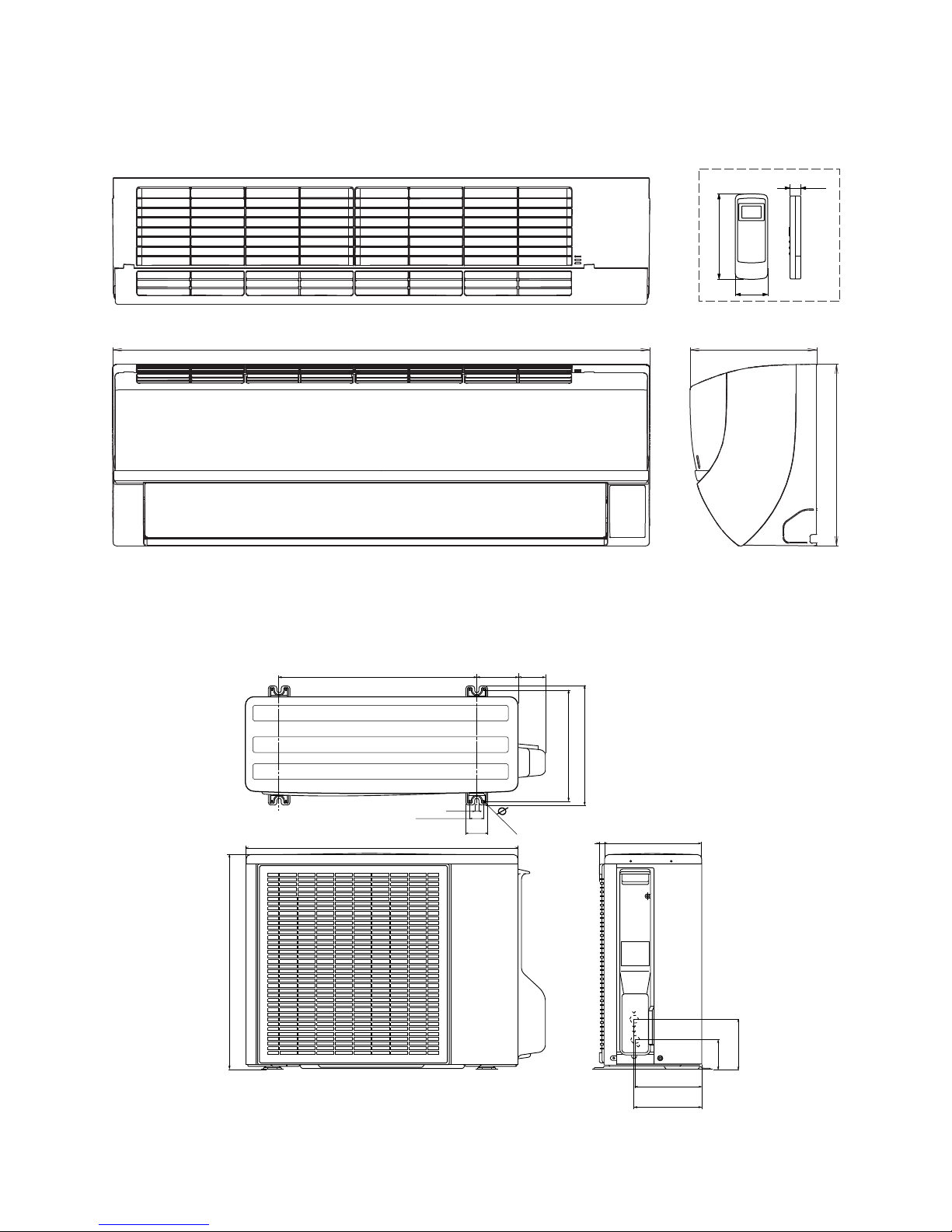
[2] EXTERNAL DIMENSION
1. Indoor unit
Length unit [mm]
Remote controller
17.5
140
57
205
292
2. Outdoor unit
Length unit [mm]
1 – 3
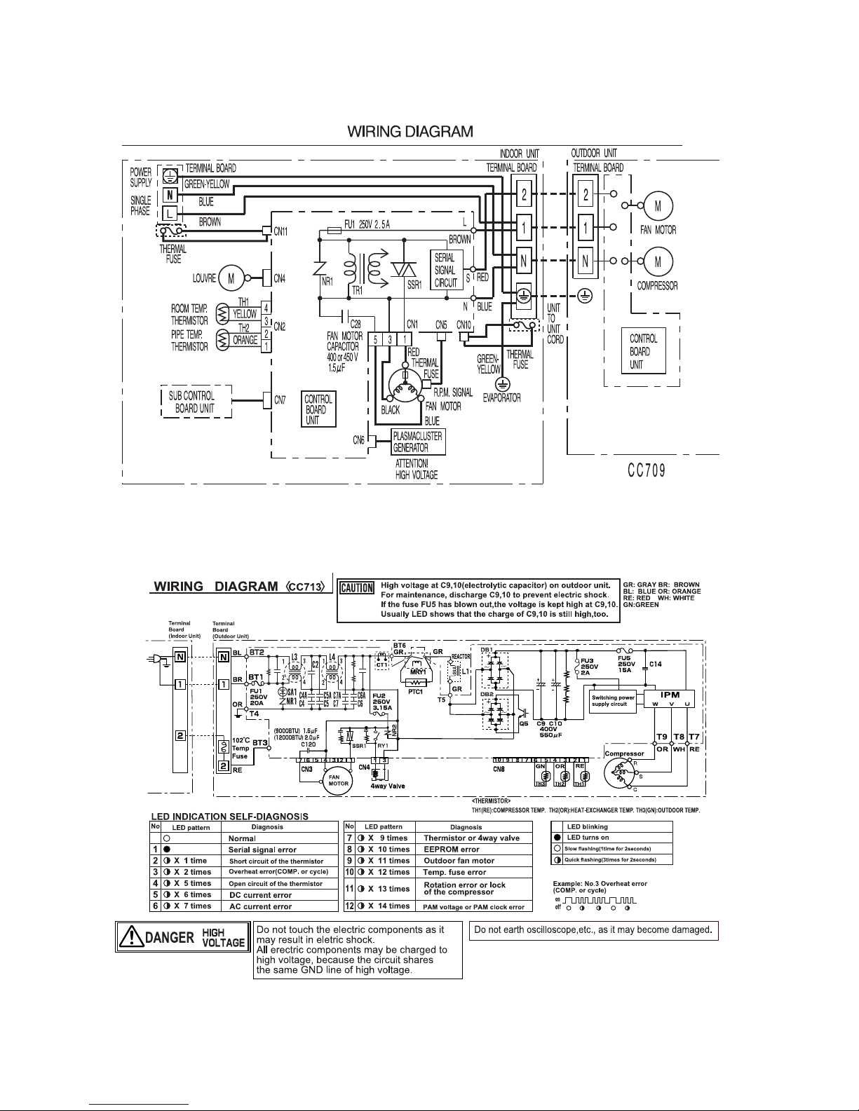
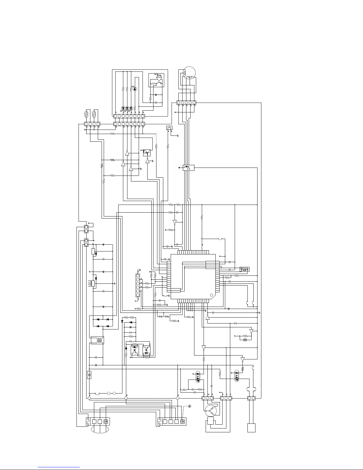
[3] WIRING DIAGRM
1. Indoor unit
AYXP9LSR
2. Outdoor unit
1 – 4

AYXP9LSR
[4] ELECTRICAL PARTS
1. Indoor unit
DESCRIPTION MODEL REMARKS
Indoor fan motor MLA521 AC Motor
Indoor fan motor capacitor DS401155BLSA RC-HZA512JBZZ (400V-1.5μF)
Transformer VRK4119–290mA RTRNPA030JBZZ
Fu1 – QFS-IA 001KK ZZ (250V, 2.5A)
2. Outdoor Unit
DESCRIPTION MODEL REMARKS
Compressor 43A23YBM&FJKE D.C. brush-less motor
Outdoor fan motor MLB452 AC Motor(AE-X12LSR)
Outdoor fan motor MLB453 AC Motor(AE-X9LSR)
Outdoor fan motor capacitor DS441155XLTD 440V, 1.5μF (AE-X9LSR) on PWB
DS441205XLTC 440V, 2.0μF (AE-X12LSR) on PWB
Fu3 – QFS-GA063JBZZ (250V, 2A)
Fu2 – QFS-GA062JBZZ (250V, 3.15A)
Fu1 – QFS-GA065JBZZ (250V, 20A)
Fu5 – QFS-GA066JBZZ (250V, 15A)
1 – 5
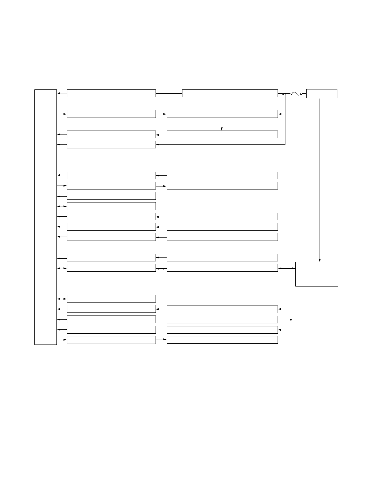
AC power
12V DC regulation
CPU
2.5A
Fuse
5VDC regulation
Fan motor phase control circuit
Rotation pulse input circuit
AC clock circuit
Remote controller signal reception circuit
Buzzer drive circuit
CPU reset circuit
CPU oscillator circuit
Room temp. detect circuit
Heat exchanger pipe thermo circuit
EEPROM
Select circuit
Serial I/O circuit
Auto restart circuit
Test run circuit
Auxiliary mode
Power on circuit
Cluster generator drive circuit
Indoor fan motor
Fan motor pulse detect
Wireless remote control operation
Audible operation confirmation
Room temp. thermistor
Heat exchanger pipe thermistor
Louvre angle, fan speed
Wireless, preheat, Model select
Indoor/outdoor control signal I/O
Test run (forced operation)
Auxiliary mode button ON/OFF
Self diagnostics, fault diagnosis
Cluster generator
Unit-unit wiring
(AC power and
serial signals)
AYXP9LSR
CHAPTER 2. EXPLAMATION OF CIRCUIT AND OPERATION
Service Manual
[1] BLOCK DIAGRAMS
1. Indoor unit
AYXP9LSR
2 – 1

AYXP9LSR
CPU
20A
protection
Fuse detector cirunit Terminal board temp.fuse
IPM heat sink temp.fuse
15A
protection
Power supply circuit
CPU oscillator circuit
DC overvoltage detection circuit
Outdoor fan drive circuit
4-way valve relay drive circuit
Power transistor module drive circuit
Serial I/O circuit
CPU reset circuit
AC overcurrent detection circuit
Compressor thermo circuit
Heat exchanger pipe thermo circuit
Outdoor temp. thermo. circuit
EEPROM
LED drive circuit
Test mode circuit
Filter
circuit
Smoothing
circuit
Pulse amplitube modulation circuit
AC clock circuit
DC overcurrent detection circuit
IGBT
Unit-unit wiring (AC power
and serial signals)
Rectification
circuit
FAN Control
3.15A
protection
Outdoor fan
4-way valve
Power transistor module
Compressor
Current transformer
Compressor thermistor
Heat exchanger pipe thermistor
Outdoor temperature thermistor
LED
2. Outdoor unit
2 – 2
㧷㧵㧰㧢㧡㧜㧜㧠㧭㧲
㧤
㧵㧯㧠
㧝㧞㨂
㧥
㧭㧼㧼㧸㧵㧯㧭㨀㧵㧻㧺˴㧹㧻㧰㧱㧸˴㧦
㧭㨅㧙㨄㧼㧝㧞㧸㧿㧾
㧭㨅㧙㨄㧼㧥㧸㧿㧾
㨅㧱㧸㧸㧻㨃
㧳㧾㧱㧱㧺㧛
㧮㧾㧻㨃㧺
㨀㧱㧾㧹㧵㧺㧭㧸
㧿㨁㧼㧼㧸㨅
㧼㧻㨃㧱㧾
㧼㧴㧭㧿㧱
㧿㧵㧺㧳㧸㧱
㧮㧻㧭㧾㧰˴㧞
㨀㧱㧾㧹㧵㧺㧭㧸
㧺㧯
㧸
㧶㧼㧟㧤
㧹㧻㨀㧻㧾
㧲㧭㧺
㧮㧸㨁㧱
㧱㧭㧾㨀㧴
㨀㧱㧾㧹㧵㧺㧭㧸
㧮㧻㧭㧾㧰˴㧝
㧞㨃
㧝㧝㧷㨤㧞
㧰㧝㧥
㧰㧝㧺㧢㧜
㧮㧯㧺㧝㧜㧝
㧷㧾㧯㧝㧜㧢
㧯㧞㧤
㧽㧝㧝
㧷㧾㧯㧝㧜㧢
㧾㧞㧟
㧠㧚㧣㧷
㧼㧴
㧾㨄㧰
㨂㧰㧰
㧳㧺㧰
㧯㧺㧣㧜
㧢㧝㧠
㧟
㨀㨄㧰
㧾㧱㧿㧱㨀
㧲㧸㧹㧰㧜
㧞㧡
㧝㧷
㧝㧷
㧾㧞㧜
㧝㧜㧜㧷
㧡㨂
㧡㨂
㧾㧤
㧝㧜㧚㧜㧷㧲
㧝Ǵ
㧞㧚㧡㧭
㧡㧜㨂
㧜㧚㧝Ǵ
㧯㧠㧞
㧽㧞
㧷㧾㧯㧝㧜㧢
㧜㧚㧝Ǵ
㧡㧜㨂
㧯㧝㧟
㧗
㧝㧜㧜Ǵ 㧝㧜㨂
㧯㧤
㧰㧝㧠 㧰㧝㧡
㧗
㧝Ǵ
㧡㧜㨂
㧯㧟㧢
㧶㧼㧻
㧭㨁㨀㧻
㧾㧱㧿㨀㧭㧾㨀
㧶㧼㨃
㨃㧵㧾㧱㧸㧱㧿㧿
㧺㧯
㧺㧯
㧺㧯
㧾㧠㧞
㧾㧠㧟
㧲
㧰
㧵㧯㧠
㧡㧜㨂
㧡㧜㨂
㧔㧴㧻㧾㧵㨆㧻㧺㨀㧭㧸㧕
㧟
㧝
㧼㧯˴㨁㧺㧵㨀˴㧝
㧮㨆㧝
㧝㧞㨂
㧯㧺㧡
㧯㧺㧢
㧺
㧰㧻㧻㧾
㧻㨁㨀㧙
㧺
㧝
㧞
㧝㧛㧞㨃
㧠㧣㧜
㧾㧟㧣
㧝㧞㨂
㧿㧿㧾㧝
㧞㧣㧡㨂
㧜㧚㧜㧟㧟Ǵ
㧯㧞㧡
㧝㧞㧜
㧝㨃
㧾㧟㧢
㧷㧾㧯㧝㧜㧢
㧯㧺㧝
㧡㧝㧟
㧵㧯
㧴㧭㧸㧸
㧽㧝
㧝㧞㨂
㧝㧛㧠㨃㧝㧚㧤㧷
㧾㧞㧞
㧽㧝㧠
㧷㧾㧯㧝㧜㧢
㧝㧛㧠㨃
㧞㧚㧣㧷
㧾㧝㧟
㧯㧝㧜
㧜㧚㧜㧝Ǵ
㧾㧝㧠
㧠㧚㧣㧷
㨀㧱㧿㨀
㧿
㧟㧚㧟㧷
㧾㧡㧞
㧡㨂
㧾㧝㧞
㧡㧢㧷
㧼㧯㧝
㧼㧯㧞˴㧼㧯㧤㧡㧟㧴
㧾㧟㧝
㧴㨆㧞㧠㧙㧞
㨆㧰㧝
㧗
㧯㧝㧡
㧟㧡㨂
㧝㧜㧜Ǵ
㧜㧚㧜㧠㧣Ǵ
㧡㧜㨂
㧯㧞㧝
㧾㧝㧢
㧝㧜㧜㧷
㧜㧚㧜㧝Ǵ
㧞㧡㧜㨂
㧾㧝㧡
㧠㧚㧣㧷
㧯㧞㧜
㧼㧯㧤㧝㧣㨄
㧰㧝㧺㧢㧜
㧰㧝㧤
㧠
㧝
㧝
㧠
㧞
㧟
㧟
㧞
㧾㧟㧞
㧞㨃
㧰㧞
㧰㧝
㧰㧟
㧰㧠
㧰㧝㨪㧰㧠
㧝㧿㧾㧝㧟㧥㧙㧢㧜㧜㨀
㧽㧣
㧽㧢
㧝㧞㨂
㧔㧯㧸㨁㧿㨀㧱㧾㧕
㧸㧱㧰㧝㧜㧡
㧾㧝㧜㧞
㧠㧚㧣㧷
㧾㧡
㧝㧷
㧾㧠㧥
㧾㧡㧝
㧝㧷
㧔㧻㧼㧱㧾㧭㨀㧵㧻㧺㧕
㧸㧱㧰㧝㧜㧟
㧾㧝㧜㧡 㧝㧛㧠㨃
㧸㧱㧰㧝㧜㧞
㧝㧛㧠㨃㧾㧝㧜㧢
㧔㨀㧵㧹㧱㧾㧕
㧸㧱㧰㧝㧜㧠
㧵㧯㧝㧜㧝
㧤
㧗
㧯㧝㧜㧝
㧝㧜㨂
㧠㧣Ǵ
㧠㧣 㧝㧛㧞㨃
㧝㧛㧠㨃㧾㧝㧜㧣
㧝
㧾㧝㧜㧝
㧢㧣㧡㧠㧟
㧞
㧿㨃㧝˴㧦˴㧭㨁㨄㧚㧔㨀㧱㧿㨀˴㧾㨁㧺㧕
㧡㧜㨂
㧜㧚㧝Ǵ
㧯㧝㧜㧞
㧢㧣㧡㧠㧟㧞㧝
㧤
㧝㧜㧷
㧾㧞㧢
㧝㧷
㧾㧡㧜
㧜㧚㧝Ǵ
㧯㧝㧢
㧡㧜㨂
㧝㧜㧷
㧾㧠㧠 㧾㧠㧡 㧝㧷
㧹㧻㨀㧻㧾
㧸㧻㨁㨂㧱㧾
㧯㧺㧠
㧝㧞㧟㧠㧡
㧝㧜㧷
㧜㧚㧜㧝Ǵ
㧯㧞㧟
㧾㧞㧣
㧟㧟㧷
㧾㧞㧤
㧟㧟㧷㧞㧜㧷
㧡㨂
㧽㧝㧣
㧝㧟㧞
㧡㨂
㧺㧯
㧟㧟
㧟㧠
㧟㧡
㧟㧢
㧟㧣
㧟㧤
㧟㧥
㧠㧜
㧠㧝
㧠㧞
㧠㧟
㧠㧠
㧠㧡
㧠㧢
㧠㧣
㧠㧤
㧢㧠㧢㧟㧢㧞㧢㧝㧢㧜㧡㧥㧡㧤㧡㧣㧡㧢㧡㧡㧡㧠㧡㧟㧡㧞
㧝㧢
㧝㧡
㧝㧠
㧝㧟
㧝㧞
㧝㧝
㧝㧜
㧥
㧤
㧣
㧢
㧡
㧠
㧟
㧞
㧝 㧼㧝㧞㧜
㧼㧠㧟
㧼㧠㧞
㧼㧠㧝
㧼㧠㧜
㧾㧱㧿㧱㨀
㧼㧝㧞㧠
㧼㧝㧞㧟
㧲㧸㧹㧰㧜
㨄㧞
㨄㧝
㧾㧱㧳㧯
㨂㧿㧿
㧱㨂㧿㧿
㨂㧰㧰
㧱㨂㧰㧰
㧭㧺㧝㧣
㧭㧺㧝㧢
㧭㧺㧝㧡
㧭㧺㧝㧠
㧭㧺㧝㧟
㧼㧞㧞
㧼㧞㧝
㧼㧞㧜
㧼㧝㧟㧜
㧼㧜㧠
㧼㧜㧟
㧼㧜㧞
㧼㧜㧜
㧵㧺㨀㧼㧢
㧭㨂㧿㧿
㧭㨂㧾㧱㧲
㨀㨤㧰㧜
㧾㨤㧰㧜
㧼㧟㧝
㧼㧡㧜
㧼㧡㧝
㧼㧡㧞
㧼㧡㧟
㧼㧟㧜
㧼㧝㧣
㧼㧝㧢
㧼㧝㧡
㧼㧝㧠
㧼㧝㧟
㧼㧝㧞
㨀㧵㧜㧜㧝
㧿㧯㧸㧜
㧼㧢㧞
㧿㧰㧭㧜
㧼㧢㧟
㧼㧟㧟
㧼㧣㧣
㧼㧣㧢
㧼㧣㧡
㧼㧣㧠
㧼㧣㧟
㧼㧣㧞
㧼㧣㧝
㧼㧣㧜
㧼㧜㧢
㧝㧣㧝㧤㧝㧥㧞㧜㧞㧝㧞㧞㧞㧟㧞㧠㧞㧡㧞㧢㧞㧣㧞㧤㧞㧥㧟㧜㧟㧝
㧟㧞㧠㧥
㧡㧜
㧡㧝
㧵㧺㨀㧼㧟
㧝㧜㧚㧜㧷㧲
㧾㧢
㧽㧟
㨀㧴㧝
㧾㧻㧻㧹˴㨀㧱㧹㧼㧚
㧝㧜㧷ǡ㧔㧞㧡㧕
㧠㧟㧞
㧝
㨀㧾㧝
㧝㧜㧜㧜Ǵ㧟㧡㨂
㧯㧡
㧗
㧻㧿㧯㧝
㧡㨂
㧝㧞㨂
㧺㧯㧺㧯㧺㧯
㧯㧞㧞
㧝㧜㧜㧜㨜
㧡㧜㨂
㧡㧜㨂
㧜㧚㧝Ǵ
㧯㧠
㧝㧞㧭㧼㧵
㧷㧵㧭㧣㧤
㧾㧞㧠
㧽㧤
㧷㧾㧯㧝㧜㧢
㧝㧜㧜㧜㨜
㧯㧝㧣
㧡㧜㨂
㧯㧝㧝
㧜㧚㧜㧝Ǵ
㧡㧜㨂
㧯㧟㧝
㧜㧚㧝Ǵ
㧠㧚㧣㧷
㧾㧞㧡
㧡㨂
㧺㧯
㧺㧯
㧺㧯
㧡㨂
㧳㧺㧰
㧯㧟㧡
㧡㧜㨂
㧜㧚㧝Ǵ
㧯㧟㧡
㧾㧝㧣
㧝㧜㧜㧷
㧺㧯
㧺㧯
㧵㧯㧞
㧵㧯㧟
㧷㧵㧭㧣㧤
㧜㧡㧭㧼㧵
㧯㧺㧝㧜
㧝㧞㨂
㧞㧡㨂㧠㧣Ǵ
㧯㧢
㧗
㧡㨂
㧽㧡
㧷㧾㧯㧝㧜㧢
㧷㧾㧯㧝㧜㧢
㧷㧾㧯㧝㧜㧢
㧷㧾㧭㧝㧜㧢
㧡㧜㨂
㧯㧥
㧴㧭㧶㧼
㧿㧭㧺
㧺㧯
㧼㧝㧠㧝
㧮㨁㨆
㧵㧯㧝
Ǵ㧼㧰㧣㧤㧲㧜㧡㧟㧠
㧞㧡㧜㨂
㧲㨁㧝
㧝㧢㧹㧴㨦
㧯㧣
㧞㧣㧡㨂
㧜㧚㧝Ǵ
㧺㧾㧝
㧝㧛㧠㨃
㧞㧝
㧯㧺㧣
㧯㧺㧞
㧾㧟㧜
㧠㧜㧜㨂
㧝㧚㧡Ǵ
㧺㧯
㧺㧯
㧺㧯㧺㧯㧺㧯
㧺㧯
㧝㧷
㧣㧡㧜
㧞㧞㧜
㧣㧡㧜
㧲㨁㧿㧱
㧝㧜㧞
㨀㧱㧾㧹㧵㧺㧭㧸
㧾㧱㧰
㧡㧜㨂
㧝㧜㧷
㧾㧞㧝
㧡㧜㨂
㧯㧝㧠
㧝㧜㧜㧜㨜
㧝㧜㧷
㧾㧝㧤
㧶㧼㧯㧞
㧝㧞㨂
㧾㧟㧥
㧝㧛㧠㨃
㧯㧝㧞
㧝㧜㧜㧜㨜
㧡㧜㨂
㧝㧜㧚㧜㧷㧲
㧾㧡
㧾㧡㧝
㧝㧷
㧝㧡㧷ǡ㧔㧞㧡㧕
㧼㧵㧼㧱˴㨀㧱㧹㧼㧚
㨀㧴㧞
㧯㧺㧝㧝
㧝㧞
㧲㨁㧿㧱
㧝㧜㧞
㧸
㧺
㨅㧱㧸㧸㧻㨃
㧳㧾㧱㧱㧺㧛
㧸㧝
㧜㧚㧜㧝Ǵ
㧞㧣㧡㨂
㧯㧞㧠
㧺㧯
㧶㧼㧞
㧝㧞㨂
㧝㧛㧞㨃
㧠㧣㧜
㧿㧿㧾㧞
㧝㧞㧜㧷㧝㨃
㧾㧟㧠
㧶㧼㧯㧝
[2] MICROCOMPUTER CONTROL SYSTEM
1. Indoor unit
1.1. Electronic control circuit diagram
AYXP9LSR
2 – 3
AYXP9LSR
1.2. Printed wiring board
Plasumacluster Generator
Fan Motor
Louver Motor
Thermistor
Terminal board "2"
Terminal board "N"
Terminal board "1"
Terminal board 4P
Terminal board 3P
2 – 4
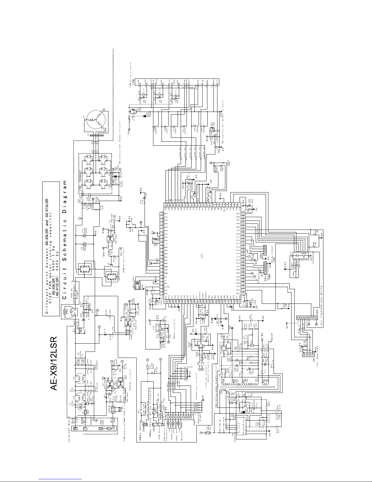
2. Outdoor unit
2.1. Electronic control circuit diagram
AYXP9LSR
2 – 5
AYXP9LSR
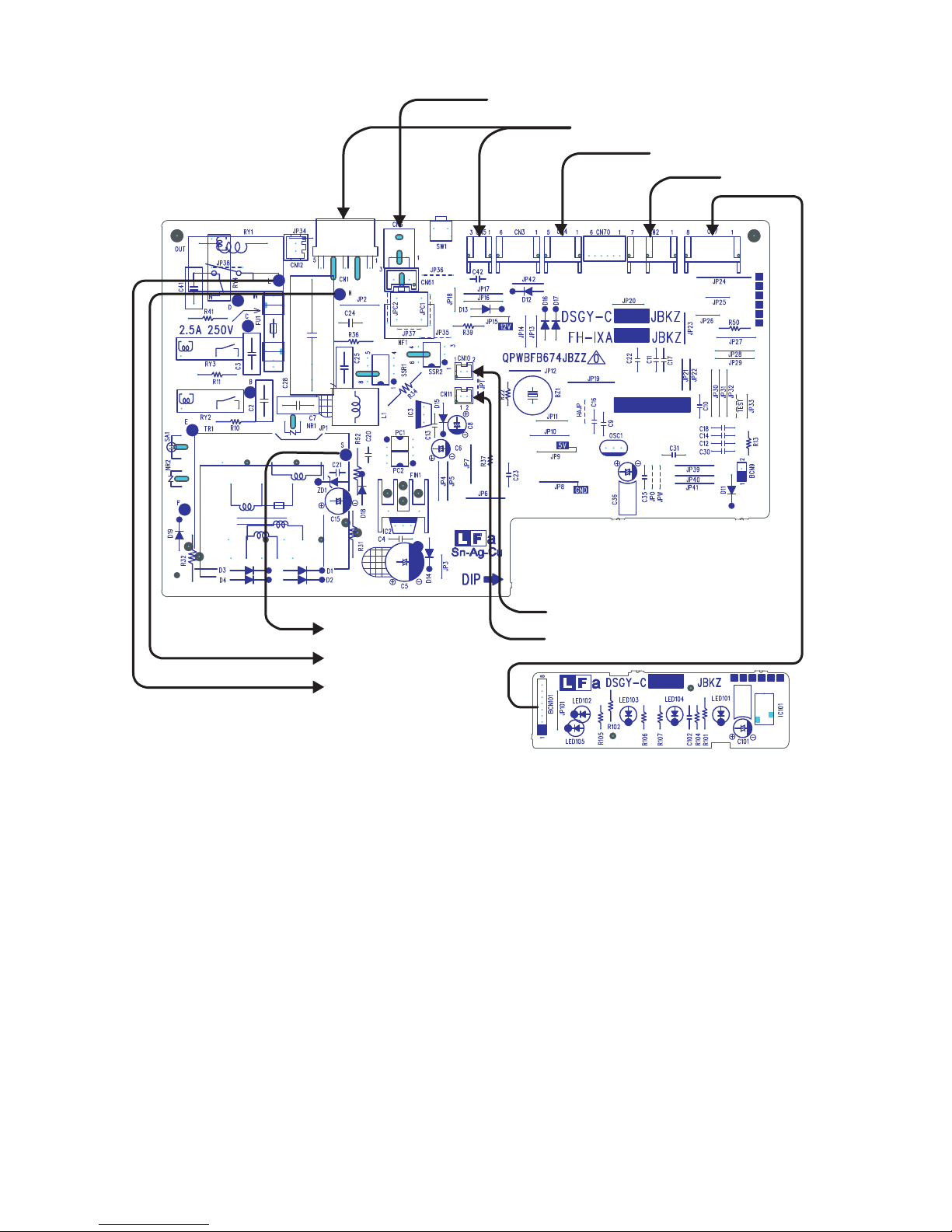
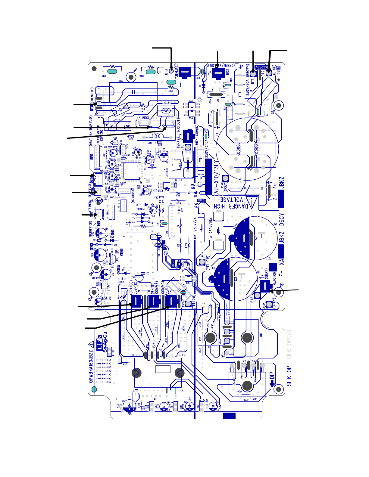
2.2. Printed wiring board
From Fan
Motor
To PWB
BT6(Gray)
To Reactor
(Gray)
From heatsink
TEMP fuse
From Terminal Board
(Themal fuse)
From Thermistor
To Terminal Board
(3)(Red)
To Control Box
(Green/Yellow)
To Terminal Board
(1)(Brown)
To Terminal Board
(N)(Blue)
From Compressor(R)
(Orange)
From Compressor(S)
(White)
From Compressor(C)
(Red)
To Reactor
(Gray)
2 – 6
[3] FUNCTION
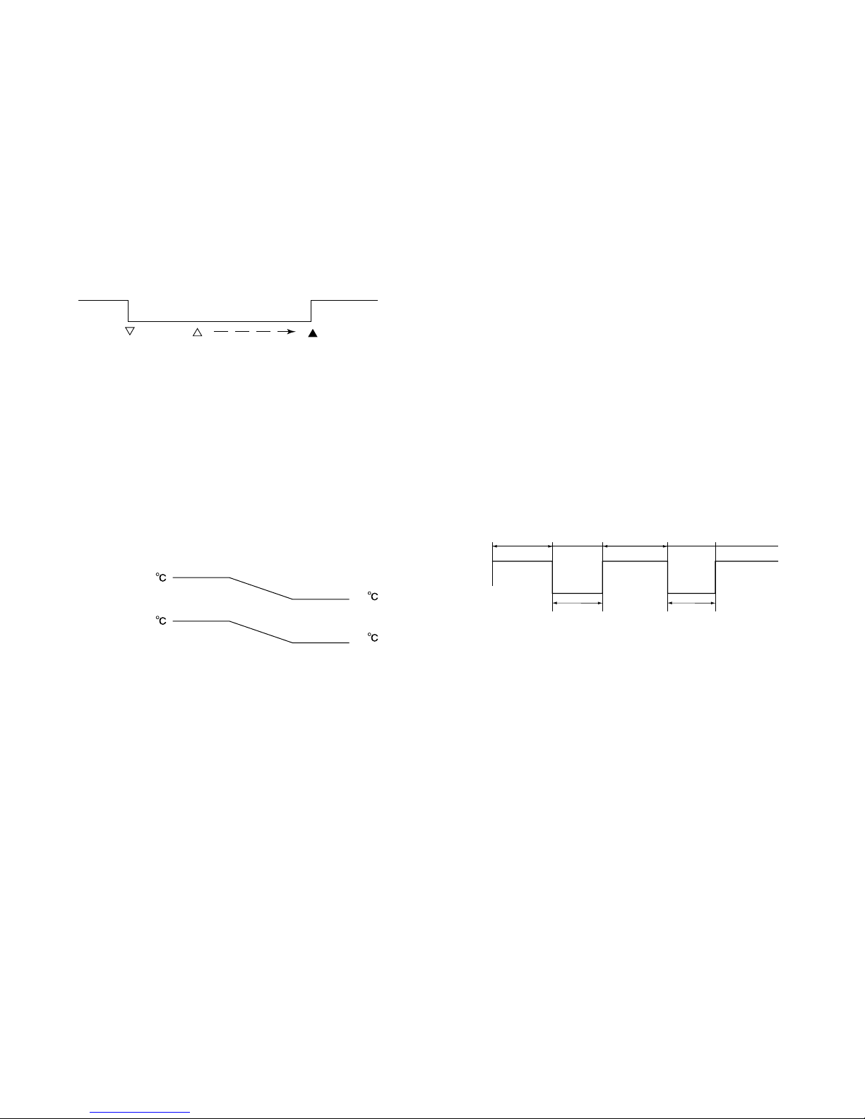
Compressor operation
ON operation on
remote control
OFF operation on
remote control
Compressor ON
Compressor ON Compressor can
turn ON
Compressor remains OFF
for 180 seconds
Indoor unit heat exchanger temperature
38
23
35
21
Set fan speed
Indoor unit fan at low speed
Indoor unit fan in non-operation
20 min or more 20 min or more 20 min or more
Defrosting
Max. 10 min
Defrosting
Max. 10 min
Start of
heating
operation
1. Function
AYXP9LSR
1.1. Restart control
Once the compressor stops operating, it will not restart for 180 seconds to protect the compressor.
Therefore, if the operating compressor is shut down from the remote
control and then turned back on immediately after, the compressor will
restart after a preset delay time.
(The indoor unit will restart operation immediately after the ON switch
is operated on the remote control.)
1.2. Cold air prevention control
When the air conditioner starts up in heating mode, the indoor unit fan
will not operate until the temperature of the indoor unit heat exchanger
reaches about 23°C in order to prevent cold air from blowing into the
room.
Also, the indoor unit fan operates at low speed until the temperature of
the indoor unit heat exchanger reaches about 38°C so that people in
the room will not feel chilly air flow.
1.5. Indoor unit overheat prevention control
During heating operation, if the temperature of the indoor unit heat
exchanger exceeds the indoor unit heat exchanger overheat prevention temperature (about 45 to 54°C) which is determined by the operating frequency and operating status, the operating frequency is
decreased by about 4 to 15 Hz. Then, this operation is repeated every
60 seconds until the temperature of the indoor unit heat exchanger
drops below the overheat protection temperature.
Once the temperature of the indoor unit heat exchanger drops below
the overheat protection temperature, the operating frequency is
increased by about 4 to 10 Hz every 60 seconds until the normal operation condition resumes.
If the temperature of the indoor unit heat exchanger exceeds the overheat protection temperature for 60 seconds at minimum operating frequency, the compressor stops operating and then restarts after about
180 seconds, and the abovementioned control is repeated.
1.6. Defrosting
1.6.1 Reverse defrosting
The defrost operation starts when the compressor operating time
exceeds 10 minutes during heating operation, as shown below, and
the outside air temperature and the outdoor unit heat exchanger temperature meet certain conditions. When the defrost operation starts,
the indoor unit fan stops. The defrost operation stops when the outdoor unit heat exchanger temperature rises to about 10°C or higher or
the defrosting time exceeds 10 minutes.
1.3. Indoor unit heat exchanger freeze prevention control
If the temperature of the indoor unit heat exchanger remains below
0°C for 4 consecutive minutes during cooling or dehumidifying operation, the compressor operation stops temporarily in order to prevent
freezing.
When the temperature of the indoor unit heat exchanger rises to 2°C
or higher after about 180 seconds, the compressor restarts and
resumes normal operation.
1.4. Outdoor unit 2-way valve freeze prevention control
If the temperature of the outdoor unit 2-way valve remains below 0°C
for 10 consecutive minutes during cooling or dehumidifying operation,
the compressor operation stops temporarily in order to prevent freezing.
When the temperature of the 2-way valve rises to 10°C or higher after
about 180 seconds, the compressor restarts and resumes normal
operation.
1.7. Outdoor unit overheat prevention control
During cooling operation, if the temperature of the outdoor unit heat
exchanger exceeds the outdoor unit heat exchanger overheat prevention temperature (about 55°C), the operating frequency is decreased
by about 4 to 15 Hz. Then, this operation is repeated every 60 seconds until the temperature of the outdoor unit heat exchanger drops to
about 54°C or lower.
Once the temperature of the outdoor unit heat exchanger drops to
about 54°C or lower, the operating frequency is increased by about 4
to 10 Hz every 60 seconds until the normal operation condition
resumes.
If the temperature of the outdoor unit heat exchanger exceeds the outdoor unit heat exchanger over heat protection temperature for (120 sec
: outdoor temperature ≥ 40°C, 60 sec : outdoor temperature < 40°C)
at minimum operating frequency, the compressor stops operating and
then restarts after about 180 seconds, and the abovementioned control is repeated.
2 – 7
AYXP9LSR
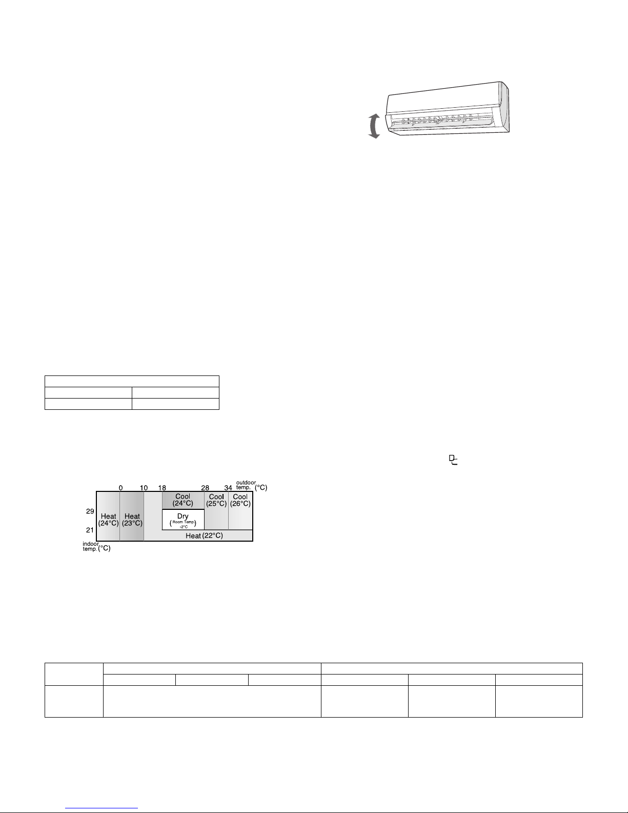
Modes and Temperature Settings
the figures in ( ) are temperature settings
1)Press the SWING button on the remote control once.
T uvre will swing continuously.
2)Press the SWING button again when the vertical airflow louvre is at
the desir ed position.
The louvre will stop moving within the range shown in the diagram.
The adjusted position will be memoried and will be automatically set
to the same position when operated the next time.
AIR FLOW DIRECTION
he vertical airflow lo .
the vert
i am.
AIR FLOW DIRECTION
.
the vert
i am.
AIR FLOW DIRECTION
٨
٨
٨
"The remote control will display"
٨
1.8. Compressor overheat prevention control
If the temperature of the compressor exceeds the compressor overheat prevention temperature (110°C), the operation frequency is
decreased by about 4 to 10 Hz. Then, this operation is repeated every
60 seconds until the temperature of the compressor drops below the
overheat protection temperature (100°C).
Once the temperature of the compressor drops below the overheat
protection temperature, the operating frequency is increased by about
4 to 10 Hz every 60 seconds until the normal operation condition
resumes.
If the temperature of the compressor exceeds the overheat protection
temperature (for 120 seconds in cooling operation or 60 seconds in
heating operation) at minimum operating frequency, the compressor
stops operating and then restarts after about 180 seconds, and the
above mentioned control is repeated.
1.9. Startup control
When the air conditioner starts in the cooling or heating mode, if the
room temperature is 2°C higher than the set temperature (in cooling
operation) or 3.5°C lower (in heating operation), the air conditioner
operates with the operating frequency at maximum. Then, when the
set temperature is reached, the air conditioner operates at the oper ating frequency determined by fuzzy logic calculation, then enters the
normal control mode after a while.
1.10. Peak control
If the current flowing in the air conditioner exceeds the peak control
current (see the table below), the operation frequency is decreased
until the current value drops below the peak control current regardless
of the frequency control demand issued from the indoor unit based on
the room temperature.
Peak control current
Cooling operation Heating operation
Approx. 6.1 A Approx. 8.2 A
1.11. AUTOMATIC AIR CONDITIONING
In the AUTO mode, the temperature setting and mode are automatically selected according to the room temperature and outdoor temperature when the unit is turned on.
1.12. Airflow control
CAUTION:
Never attempt to adjust the louvres manually.
•Manual adjustment on the louvres can cause the unit to malfunction.
Position in the COOL or DRY mode for an extended period of time,
•When the vertical airflow louvre is positioned at the lowest
condensation may result.
1.12.1 COANDA Airflow
Press the COANDA AIRFLOW button during cooling or dry operat ion
when you do not want to feel cold air.
Vertical airflow louvre is set obliquely upward to deliver cool air to the
ceiling.
Press the button during heating operation. Vertical airflow louvre is set
downward to deliver the warm air down to the floor and warm you.
During operation, press the COANDA AIRFLOW button.
During operation, if the outdoor temperature changes, the temperature
settings will automatically slide as shown in the chart.
1.13. Difference of operation in Auto and Manual modes
In the Auto mode, the temperature setting is automatically determined based on the outside air temperature. In addition, the air conditioner operation
differs from the operation in the Manual mode as explained below.
1.13.1 Difference relating to set temperature
Auto mode Manual mode
Cooling Heating Dehumidifying Cooling Heating Dehumidifying
Temperature
setting
method
Automatic temperature setting based on inside air temperature. Can be changed within ±2°C using remote control.
TO CANCEL
Press the COANDA AIRFLOW button again.
NOTE:
•The COANDA AIRFLOW setting is cancelled
When you press Full power button while COANDA AIRFLOW is set.
•If you want COANDA AIRFLOW operation in Full power mode,
press COANDA AIRFLOW button during Full power operation.
Can be changed
between 18 and 32°C
using remote control.
Can be changed
between 18 and 32°C
using remote control.
Automatic setting.
Can be changed
within ±2°C.
2 – 8
1.14. Dehumidifying operation control
27ºC
+0
+0.5
-1.0
-1.5
25ºC
25ºC
28ºC
22ºC
22ºC
Room Temperature
Preset temperature
-
The remote control will display” “
The temperature display will go off.
The green Full power lamp ( ) on the unit will light up.
٨
٨
٨
The green Full power lamp ( ) on the unit will turn off.
٨
Heating operation Fan operation
24OC
Outside air temperature
Heating operation
Set temperature
Activation of
OFF timer
1hour
later
Max.
1.5 hours
later
Max.
2 hours
later
Timer setting
reached
1hour
later
Max.
1.5 hours
later
Max.
2 hours
later
Timer setting
reached
Activation of
OFF timer
Set temperature
-1
O
C
-1
O
C
-1
O
C
0.3
O
C
0.3
O
C
0.3
O
C
Cooling/dehumidifying operation
In the Dehumidifying mode, the temperature setting is automatically
determined based on the outside air temperature. In addition, the air
conditioner operation differs from the operation in the Manual mode as
explained below.
1.15. Full power Operation
In this operation, the air conditioner works at the maximum power to
make the room cool rapidly.
During operation, press the Full power button.
AYXP9LSR
1.17. Plasmacluster Ion function
The Plasmacluster Ion generator inside the air conditioner will release
positive and negative plasmacluster ions into the room.
ApproXimately the same numbers of positive and negative ions
released into the air will reduce some airborne mold.
If the Plasmacluster Ion generation function is operated together with
the air conditioner operation, the indoor unit fan speed and louver
direction are in accordance with the air conditioner settings.
If the Plasmacluster Ion generation function is used without operating
the air conditioning function, the indoor unit fan operates at a very low
speed and the upper louver is angled upward and the lower louver
remains horizontal. (The airflow volume and direction can be changed
by using the remote control.)
1.18. Power ON start
If a jumper cable is inserted in the location marked with HAJP on the
indoor unit control printed circuit board (control PCB), connecting the
power cord to an AC outlet starts the air conditioner in either cooling or
heating mode, which is determined automatically by the room temperature sensor.
When a circuit breaker is used to control the ON/OFF operation,
please insert a jumper as described above.
1.19. ON timer
The ON timer can be activated by pressing the ON timer button. When
the ON timer is activated, the operation start time is adjusted based on
fuzzy logic calculations 1 hour before the set time so that the room
temperature reaches the set temperature at the set time.
TO CANCEL
Press the Full power button again.
The Full power operation will also be cancelled when the operation
mode is changed, or when the unit is turned off.
NOTE:
•The air conditioner will operation at “Extra HIGH” fan speed for 5
minutes, and then shift to “HIGH” fan speed.
• You can not set the temperature or fan speed during the Full power
operation.
• To turn off the Full power lamp, press the DISPLAY button.
1.16. Self Clean operation
Heating or Fan operation and Cluster operation are performed simultaneously.
The judgment of whether Heating or Fan operation is used is based on
the outside air temperature at 3 minutes after the start of internal
cleaning.
The operation stops after 40 minutes.
• During this operation the horizontal louver moves and stays two posi-
tions.
It turns to the lower direction and stays for 30 minutes.
Next moves upward and stays for 10 minutes.
1.20. OFF timer
The OFF timer can be activated by pressing the OFF timer button.
When the OFF timer is set, the operation stops after the set time.
When this timer is set, the compressor operating frequency lowers for
quieter operation, and the room temperature is gradually varied after
one hour (reduced 1°C three times (max. 3°C) in heating, or increased
0.3°C three times (max. 1°C) in cooling or dehumidifying operation) so
that the room temperature remains suitable for comfortable sleeping.
1.21. Auto restart
When power failure occurs, after power is recovered, the unit will automatically restart in the same setting which were active before the
power failure.
1.21.1 Setting not memorized
• Timer setting
• Full power operation setting
• Self clean operation
2 – 9
AYXP9LSR
1
3
SSR2
R39
Q11
Microcomputer output
1
4
Cluster unit
JPC1
JPC2
AC220-240V
12V
R34
PAM drive circuit block diagram
Reactor L1
[PAM drive circuit]
+
Microcomputer (IC1)
AC
230V
Compressor
Noise
filter
AC clock
detection
circuit
DB1
IPM
DB2
Compressor
position
detector
IGBT
drive
circuit
IGBT
Overvoltage
detection
circuit
1.21.2 Disabling auto restart function
By removing (cutting) jumper O (JP O) on the printed circuit board
(PCB), the auto restart function can be disabled.
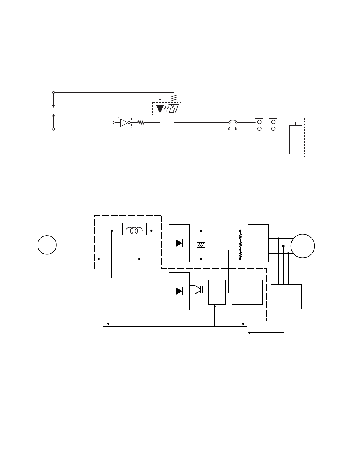
2. Explanation of cluster circuit
The cluster unit generates cluster ions, which are circulated throughout the room by the air flow created by the blower fan (indoor unit fan motor) in
the air conditioner unit.
1) When microcomputer output turns "H," the Q11 output changes to "Lo," turning ON the SSR2 and applying 100 V to the cluster unit for the generation of cluster ions (positive and negative ions).
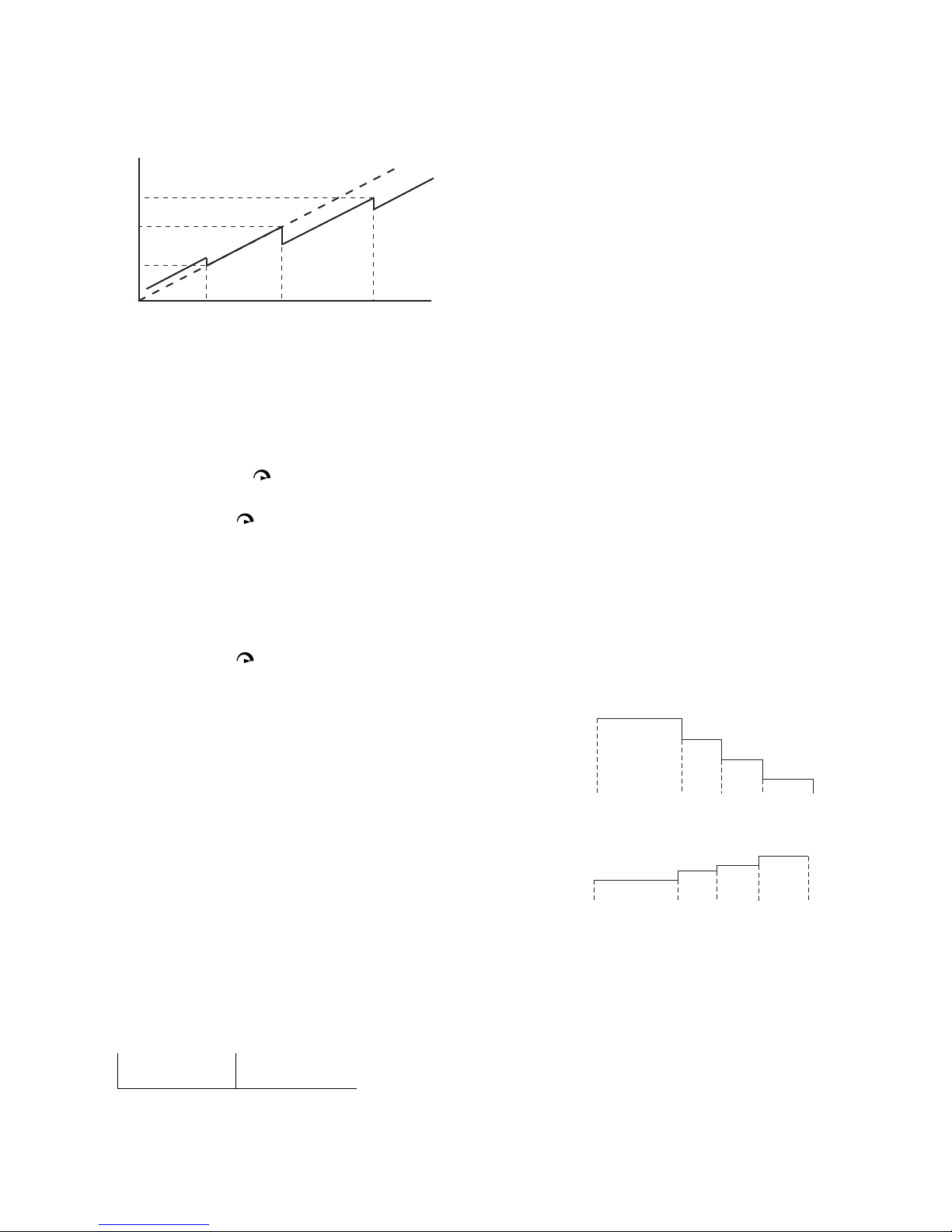
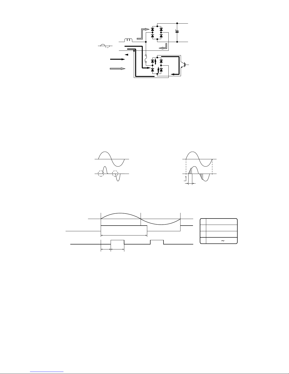
3. Outline of PAM circuit
3.1. PAM (Pulse Amplitude Modulation)
The PAM circuit varies the compressor drive voltage and controls the rotation speed of the compressor.
The IGBT shown in the block diagram charges the energy (electromotive force) generated by the reactor to the electrolytic capacitor for the inverter
by turning ON and OFF.
When the IGBT is ON, an electric current flows to the IGBT via the reactor (L1) and diode bridge (DB2).
When the IGBT turns OFF, the energy stored while the IGBT was ON is charged to the voltage doubler capacitor via the diode bridge (DB1).
As such, by varying the ON/OFF duty of the IGBT, the output voltage is varied.
2 – 10
AYXP9LSR
Stored energy
Reactor
L1
DB1
DB2
IGBT
IGBT ON
IGBT OFF
AC voltage waveform
AC voltage and current waveform when PAM is ON
AC current waveform
IGBT ON period
Zero-cross detection
AC voltage waveform
AC current waveform
AC voltage and current waveforms when PAM is OFF
AC voltage waveform
Clock
IGBT ON
A
BC
A
B
C
50Hz
11mS
1.0mS
0.25 2.3mS
CDQWV
CDQWV
3.2. High power factor control circuit
This circuit brings the operating current waveform closer to the waveform of commercial power supply voltage to maintain a high power factor.
Because of the capacitor input, when the PAM circuit is OFF, the phase of the current waveform deviates from the voltage waveform as shown below.
To prevent this deviation, a current is supplied during the periods indicated by "O" in the diagram.
To determine the length of period to supply a current, the zero-cross timing of the AC input voltage is input to the microcomputer via the clock circuit.
The power source frequency is also determined at the same time.
The IGBT turns ON after the time length determined by the zero-cross point to supply a current to the IGBT via the reactor.
This brings the current waveform closer to the voltage waveform in phase.
As described above, the ON/OFF operation of the IGBT controls the increase/decrease of the compressor power supply voltage (DC voltage) to
improve the compressor efficiency and maintain a high power factor by keeping the current phase closer to that of the supply voltage.
3.2.1 Detailed explanation of PAM drive circuit sequence
3.2.2 AC clock (zero-cross) judgment
• The clock circuit determines the time from one rising point of the clock waveform to the next rising point.
The detected clock waveform is used to judge the power source frequency (50Hz).
• The zero-cross of the AC voltage is judged as the rising of the clock waveform, as shown in the diagram above.
3.2.3 IGBT ON start time (delay time B)
• Based on the zero-cross of the AC voltage, the IGBT turns ON after a delay time set according to the power source frequency.
3.2.4 IGBT ON time (C)
• After the above delay time, the IGBT turns ON to supply a current to the reactor.
• The ON time of the IGBT determines the amount of energy (level of DC voltage rise) supplied to the reactor.
DC voltage level in each operation mode (varies depending on external load conditions)
– Cooling operation --- 220 to 290 V
2 – 11

AYXP9LSR
R125
270K
C10C9
R126
270K
R127
13K
R128
13K
0V
0V
5V
(Overvoltage detection)
During abnormal voltage output
IC
69
3.3. PAM protection circuit
To prevent excessive voltage of PAM output from
damaging the IPM and electrolytic capacitor as well
as the control printed circuit board (PCB), this circuit
monitors the PAM output voltage and turns off the
PAM control signal and PAM drive immediately
when an abnormal voltage output is generated. At
the same time, it shuts off the compressor operation.
The protection voltage level is as follows.
3.3.1 Details of troubleshooting procedure
for PAM
1) PAM shutdown due to error
1) When the DC voltage detection circuit sends a
signal exceeding the specified voltage to the
microcomputer
DC voltage of 400 V or higher
DC voltage of 184 V or less.
– When an error is detected
• PAM IGBT turns OFF.
• Compressor turns OFF.
• All units shut down compietely when the error occurs four times.
2) When the outdoor unit clock waveform differs from the specified value immediately before the PAM IGBT turns ON
When there is no clock waveform input
When a clock signal of other than specified power source frequency (50Hz) is input
– When an error is detected
• PAM IGBT does not turn ON.
• Compressor operates normally.
• Complete shutdown does not occur.
2) PAM error indication
In case of error “1)”
– An error signal is sent to the indoor unit as soon as an error is generated.
• Malfunction No. 14-0 is indicated when the error code is called out by the indoor unit's self-diagnosis function.
– The LED on the outdoor unit flashes 14 times when an error is generated.
• The LED continues flashing in the 14-time cycle even after the compressor stops operating.
• The LED turns off (data is deleted from the memory) when the outdoor unit power is turned off.
In case of error “2)”
– An error signal is sent to the indoor unit as soon as an error is judged.
• Malfunction No. 14-1 is indicated when the error code is called out by the indoor unit's self-diagnosis function.
– The LED on the outdoor unit flashes 14 times when an error is judged.
• The LED on the outdoor unit flashes in normal pattern when the compressor stops operating.
(Compressor OFF or Thermostat OFF from remote control)
* When a user complains that the air conditioner does not provide sufficient cool air or warm air
In addition t o conventional er ror-generating reasons, there is a possibility that the PAM IGBT does not turn ON even if the compressor is operating.
In that case, the DC voltage does not rise even though the compressor is operating, and lowers to the 180-VDC level.
– Check items
• Clock circuit check
•PAM IGBT check
• Fuse (Fu6) open-circuit check
2 – 12
 Loading...