

Page 1

AR-PB2
CODE: 00ZARPB2///1E
DIGITAL COPIER OPTION
PRINTER UNIT
MODEL AR-PB2
CONTENTS
[ 1 ] SYSTEM CONFIGURATION . . . . . . . . . . . . . . . . . . . . . . . . . . . 1-1
[ 2 ] SPECIFICATION . . . . . . . . . . . . . . . . . . . . . . . . . . . . . . . . . . . . 2-1
[ 3 ] SETUP . . . . . . . . . . . . . . . . . . . . . . . . . . . . . . . . . . . . . . . . . . . . 3-1
[ 4 ] SETTING AND ADJUSTMENTS . . . . . . . . . . . . . . . . . . . . . . . . 4-1
[ 5 ] PRINTER DRIVER CONFIGURATION . . . . . . . . . . . . . . . . . . . 5-1
[ 6 ] CONFIGURATION REPORT AND TEST PAGE . . . . . . . . . . . . 6-1
[ 7 ] FIRMWARE VERSION UP . . . . . . . . . . . . . . . . . . . . . . . . . . . . . 7-1
[ 8 ] FUNCTION AND OPERATION . . . . . . . . . . . . . . . . . . . . . . . . . 8-1
[ 9 ] CIRCUIT DIAGRAM . . . . . . . . . . . . . . . . . . . . . . . . . . . . . . . . . . 9-1
PARTS GUIDE
Parts marked with "!" is important for maintaining the safety of the set. Be sure to replace these parts with specified
ones for maintaining the safty and performance of the set.
This document has been published to be used
SHARP CORPORATION
for after sales service only.
The contents are subject to change without notice.
Page 2

AR-PB2
CONTENTS
[ 1 ] SYSTEM CONFIGURATION . . . . . . . . . . . . . . . . . . . .1-1
1. Hardware . . . . . . . . . . . . . . . . . . . . . . . . . . . . . . . . .1-1
A. Main Unit . . . . . . . . . . . . . . . . . . . . . . . . . . . . . . . .1-1
B. System Elements . . . . . . . . . . . . . . . . . . . . . . . . . .1-1
C. Input/Output Device Options . . . . . . . . . . . . . . . . .1-1
D. Accessory and Options . . . . . . . . . . . . . . . . . . . . . .1-2
2. Software Configuration . . . . . . . . . . . . . . . . . . . . . . . .1-2
[ 2 ] SPECIFICATION . . . . . . . . . . . . . . . . . . . . . . . . . . . . . . .2-1
1. General Specification . . . . . . . . . . . . . . . . . . . . . . . . . .2-1
A. PS Specification . . . . . . . . . . . . . . . . . . . . . . . . . . .2-1
2. Printing Function Specification . . . . . . . . . . . . . . . . . . .2-1
A. Outline . . . . . . . . . . . . . . . . . . . . . . . . . . . . . . . . . .2-1
B. Details . . . . . . . . . . . . . . . . . . . . . . . . . . . . . . . . . .2-1
(1) Printer Drivers . . . . . . . . . . . . . . . . . . . . . . . .2-1
(2) Printer Controller . . . . . . . . . . . . . . . . . . . . . .2-1
a. Hardware . . . . . . . . . . . . . . . . . . . . . . . . .2-1
b. Firmware . . . . . . . . . . . . . . . . . . . . . . . . . .2-2
c. Emulation . . . . . . . . . . . . . . . . . . . . . . . . .2-2
(3) Engine Spec . . . . . . . . . . . . . . . . . . . . . . . . . . .2-2
(4) Paper Handling Specification . . . . . . . . . . . . . .2-2
a. Outline . . . . . . . . . . . . . . . . . . . . . . . . . . .2-2
b. Details . . . . . . . . . . . . . . . . . . . . . . . . . . . .2-3
<1> Paper Input . . . . . . . . . . . . . . . . . . . . . . .2-3
<2> Duplex Unit (ADU) . . . . . . . . . . . . . . . . .2-3
<3> Paper Output . . . . . . . . . . . . . . . . . . . . .2-3
<4> Detactable Media Sizes in the
Bypass Tray . . . . . . . . . . . . . . . . . . . . . .2-8
(5) Print Area . . . . . . . . . . . . . . . . . . . . . . . . . . . . .2-8
(6) Font . . . . . . . . . . . . . . . . . . . . . . . . . . . . . . . . .2-8
a. Resident Font . . . . . . . . . . . . . . . . . . . . . .2-8
b. Download Fonts . . . . . . . . . . . . . . . . . . . .2-9
(7) Interface Specification . . . . . . . . . . . . . . . . . . .2-9
(8) Network Specification . . . . . . . . . . . . . . . . . . . .2-9
[ 3 ] SETUP . . . . . . . . . . . . . . . . . . . . . . . . . . . . . . . . . . . . . . . .3-1
1. Parts list . . . . . . . . . . . . . . . . . . . . . . . . . . . . . . . . . . . .3-1
2. Preliminary work . . . . . . . . . . . . . . . . . . . . . . . . . . . . .3-1
3. Hardware setup . . . . . . . . . . . . . . . . . . . . . . . . . . . . . .3-1
A. Common work . . . . . . . . . . . . . . . . . . . . . . . . . . . .3-1
(1) Printer unit installation . . . . . . . . . . . . . . . . . . .3-1
(2) Expansion memory installation . . . . . . . . . . . .3-3
B. Stand-alone environment
(Printer (parallel) cable connection) . . . . . . . . . . . .3-3
C. Network environment
(Network card installation) . . . . . . . . . . . . . . . . . . .3-4
4. Setup on the copier side . . . . . . . . . . . . . . . . . . . . . . .3-4
A. Setup by simulation . . . . . . . . . . . . . . . . . . . . . . . .3-4
B. Setup by key operator program . . . . . . . . . . . . . . .3-4
5. Software installation and setup . . . . . . . . . . . . . . . . . .3-4
A. Printer driver installation . . . . . . . . . . . . . . . . . . . . .3-5
Windows 95 . . . . . . . . . . . . . . . . . . . . . . . . . . . . . .3-5
Windows 98 . . . . . . . . . . . . . . . . . . . . . . . . . . . . . .3-5
Windows 3.1x . . . . . . . . . . . . . . . . . . . . . . . . . . . . .3-5
Windows NT . . . . . . . . . . . . . . . . . . . . . . . . . . . . . .3-6
Macintosh . . . . . . . . . . . . . . . . . . . . . . . . . . . . . .3-6
6. Setup up under network environment . . . . . . . . . . . . .3-6
[ 4 ] SETUP AND ADJUSTMENTS . . . . . . . . . . . . . . . . . . .4-1
1. Configuration setting . . . . . . . . . . . . . . . . . . . . . . . . . .4-1
A. Printer setting . . . . . . . . . . . . . . . . . . . . . . . . . . . . .4-2
B. Interface Settings . . . . . . . . . . . . . . . . . . . . . . . . . .4-2
C. Network Settings . . . . . . . . . . . . . . . . . . . . . . . . . .4-2
D. Print Test Page . . . . . . . . . . . . . . . . . . . . . . . . . . . .4-2
E. Initialization and/or Storage Setting . . . . . . . . . . . .4-3
2. Key operator program . . . . . . . . . . . . . . . . . . . . . . . . .4-3
3. Hardware setup and adjustments . . . . . . . . . . . . . . . .4-6
A. Flash Memory write protect setting . . . . . . . . . . . .4-6
B. Laser power setup . . . . . . . . . . . . . . . . . . . . . . . . .4-6
C. Centro interface adjustment . . . . . . . . . . . . . . . . . . 4-6
(1) Centro interface timing adjustment . . . . . . . . .4-6
(2) SELECT IN signal setup . . . . . . . . . . . . . . . . .4-6
D. NVRAM clear . . . . . . . . . . . . . . . . . . . . . . . . . . . . . 4-6
E. Network card check . . . . . . . . . . . . . . . . . . . . . . . . 4-6
[ 5 ] Printer Driver C onf i guration . . . . . . . . . . . . . . . . . . . .5-1
1. PCL5E Printer Driver . . . . . . . . . . . . . . . . . . . . . . . . . .5-1
2. PostScript Printer Driver(Windows) . . . . . . . . . . . . . .5-10
3. PostScript PPD Printer Driver(Windows) . . . . . . . . . . 5-20
[ 6 ] Configurati on Report and Test Page . . . . . . . . . . . . 6-1
1. Samples . . . . . . . . . . . . . . . . . . . . . . . . . . . . . . . . . . . .6-1
2. Description of Each contents . . . . . . . . . . . . . . . . . . . . 6-1
A. Hardware Status . . . . . . . . . . . . . . . . . . . . . . . . . . 6-1
B. Software Information . . . . . . . . . . . . . . . . . . . . . . . 6-3
[ 7 ] FIRMWARE VERSION UP . . . . . . . . . . . . . . . . . . . . . .7-1
[ 8 ] FUNCTION AND OPERATION . . . . . . . . . . . . . . . . . . . 8-1
1. Multi Function . . . . . . . . . . . . . . . . . . . . . . . . . . . . . . .8-1
2. Printer Operation / Message Display . . . . . . . . . . . . . . 8-2
3. Emulation Switch . . . . . . . . . . . . . . . . . . . . . . . . . . . . .8-3
4. Resolution . . . . . . . . . . . . . . . . . . . . . . . . . . . . . . . . . . 8-3
5. Font . . . . . . . . . . . . . . . . . . . . . . . . . . . . . . . . . . . . . . . 8-3
A. Font Handling . . . . . . . . . . . . . . . . . . . . . . . . . . . . .8-3
B. Downloadable Font Types . . . . . . . . . . . . . . . . . . . 8-3
C. Location of Font Data . . . . . . . . . . . . . . . . . . . . . . .8-3
D. Font Data Memory Map . . . . . . . . . . . . . . . . . . . . . 8-3
6. Language . . . . . . . . . . . . . . . . . . . . . . . . . . . . . . . . . . .8-3
A. Language Selection . . . . . . . . . . . . . . . . . . . . . . . . 8-3
B. Job, control . . . . . . . . . . . . . . . . . . . . . . . . . . . . . . .8-3
7. Host I/O Port Selection . . . . . . . . . . . . . . . . . . . . . . . . 8-3
A. Non-booklet mode . . . . . . . . . . . . . . . . . . . . . . . . . . 8-4
8. ERDH Operation . . . . . . . . . . . . . . . . . . . . . . . . . . . . . 8-5
A. Hard Disk Capacity and Operation . . . . . . . . . . . . .8-5
9. Printing Modes . . . . . . . . . . . . . . . . . . . . . . . . . . . . . . .8-5
10. Basic Face-up /down Controls and Defaults . . . . . . . .8-7
11. Duplex with Multiple Paper Sources . . . . . . . . . . . . . .8-7
12. Binding Edge . . . . . . . . . . . . . . . . . . . . . . . . . . . . . .8-7
13. Memory Configuration . . . . . . . . . . . . . . . . . . . . . . . . .8-8
14. Printer control PWB switch (short pin) and
LED display . . . . . . . . . . . . . . . . . . . . . . . . . . . . . . . . . 8-8
(Error Messages)
[ 9 ] CIRCUIT DIAGRAM
1. Block Diagram . . . . . . . . . . . . . . . . . . . . . . . . . . . . . . .9-1
A. General Block Diagram . . . . . . . . . . . . . . . . . . . . . 9-2
B. CPU Block . . . . . . . . . . . . . . . . . . . . . . . . . . . . . . .9-4
C. ROM Block . . . . . . . . . . . . . . . . . . . . . . . . . . . . . . . 9-5
D. DRAM Block . . . . . . . . . . . . . . . . . . . . . . . . . . . . . .9-6
E. I/O Block (SCSI I/F) . . . . . . . . . . . . . . . . . . . . . . . . 9-7
F. I/O Block (CENTRO I/F) . . . . . . . . . . . . . . . . . . . . . 9-8
G. I/O Block (EXTERNAL I/F for DPI NIC) . . . . . . . . . 9-9
H. I/O Block (I/O, LED, DIP SW) . . . . . . . . . . . . . . . . 9-10
2. Circuit Diagram . . . . . . . . . . . . . . . . . . . . . . . . . . . . .9-11
A. PRINT CONTROL PWB . . . . . . . . . . . . . . . . . . . .9-11
B. NETWORK I/F PWB . . . . . . . . . . . . . . . . . . . . . . 9-50
C. MOTHER PWB . . . . . . . . . . . . . . . . . . . . . . . . . .9-51
3. Parts Location . . . . . . . . . . . . . . . . . . . . . . . . . . . . . . 9-53
A. PRINT CONTROLLER PWB . . . . . . . . . . . . . . . . 9-53
B. MOTHER PWB . . . . . . . . . . . . . . . . . . . . . . . . . . 9-54
. . . . . . . . . . . . . . . . . . . . . . . . . . . .9-1
• PARTS GUIDE
Page 3
[1] SYSTEM CONFIGURATION
(BT)
(
y)
(
)
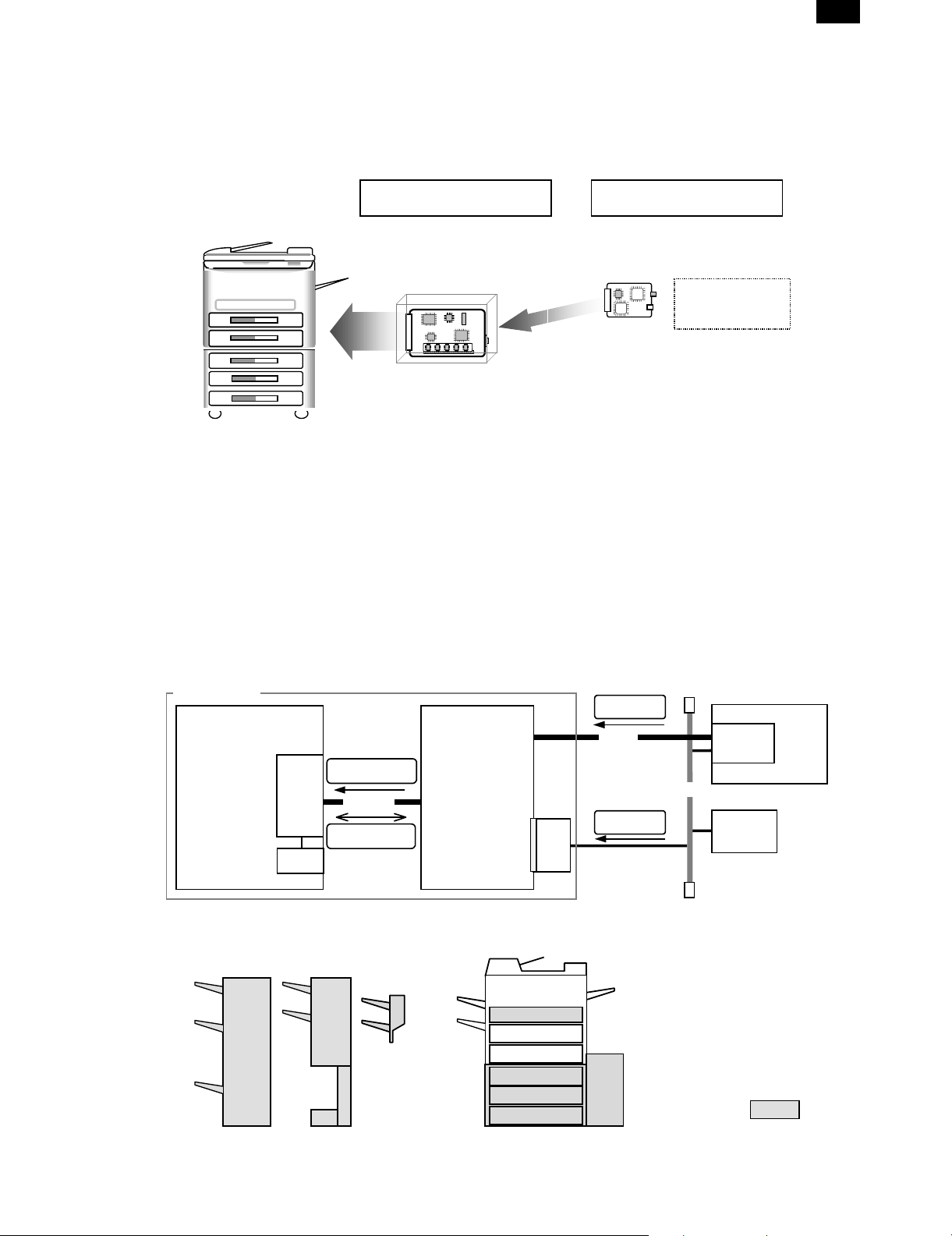
1. Hardware
A. Main Unit
Printer Expansion Kit Network Server Card
AR-PB2
AR-PB2
(1) Print Controller Hardware and Options
Controller Hardware
Hardware configuration is as follows:
• ProcessorR 4700
• Base Memory 16 MB
• Flash Memory 1 slot with 8 MB
• Memory Expansion 2 Standard 72 pin SIMM slots
• Parallel Interface 1 IEEE 1284 compatible Type B
• Network Expansion Slot 1 Internal slot
B. System Elements
AR-PB2 printer
Copier Printer Controller
Bitmap data
ICU
eRDH
SCSI I/F
command/status
AR-NC1D
10BaseT/2
(2) Options
DRAM
The system can optionally be configured with up to 64-MB optional
DRAM Using industry standard, 16 or 32 Mb72 pin SIMMs.
Network Server Card
AR-PB2 Printing system can optionally be configured with Network
Server Card of supporting 10BaseT/2
Windows PC
Own
Printer
Driver
UNIX
NIC
(DPI)
Print data/
Setting data
P1284
Print data/
Setting data
Ethernet
C. Input/Output Device Options
3Tray
Finisher
2Tray
Finisher
2Tray
Output
STD Output
(1Tray) or
2Tra
Tray5
1 – 1
ADU
Tray1
Tray2
Tray3
Tray4
Only Domestic
Bypass Tray
LCC
Option
Page 4
AR-PB2
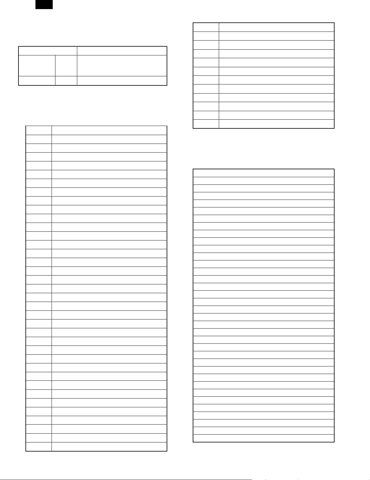
D. Accessory and Options
Part name Model Q’ty Note
Accessories SCSI cable 1
Wire saddle 1
Band 1
Printer box installing screw 5
Printer control PWB 1 With frame
Printer driver Windows 95 PCL5E Driver (FD) 1
Windows NT PCL5E Driver (FD) 1
Windows 95 PS Driver (FD) 1
Windows NT PS Driver (FD) 1
MAC PS Driver (FD) 1
Installation manual 1
Operation Manual 1
Label 1 Only for Sweden and Norway
Option SIMM memory 16MB ED0 type/Without parity/70ns or above
32MB
Network card AR-NC1D 1 10BASE T
Separate purchase
Printer (parallel) cable Necessary when the copier is used as a
(User purchase)
The copier ICU PWB requires the total
memory of 16MB(20MB) or more.
The printer control PWB has two expansion
slots to which 16MB or 32MB memory can
be additionally installed. (16MB onboard)
stand-alone machine.
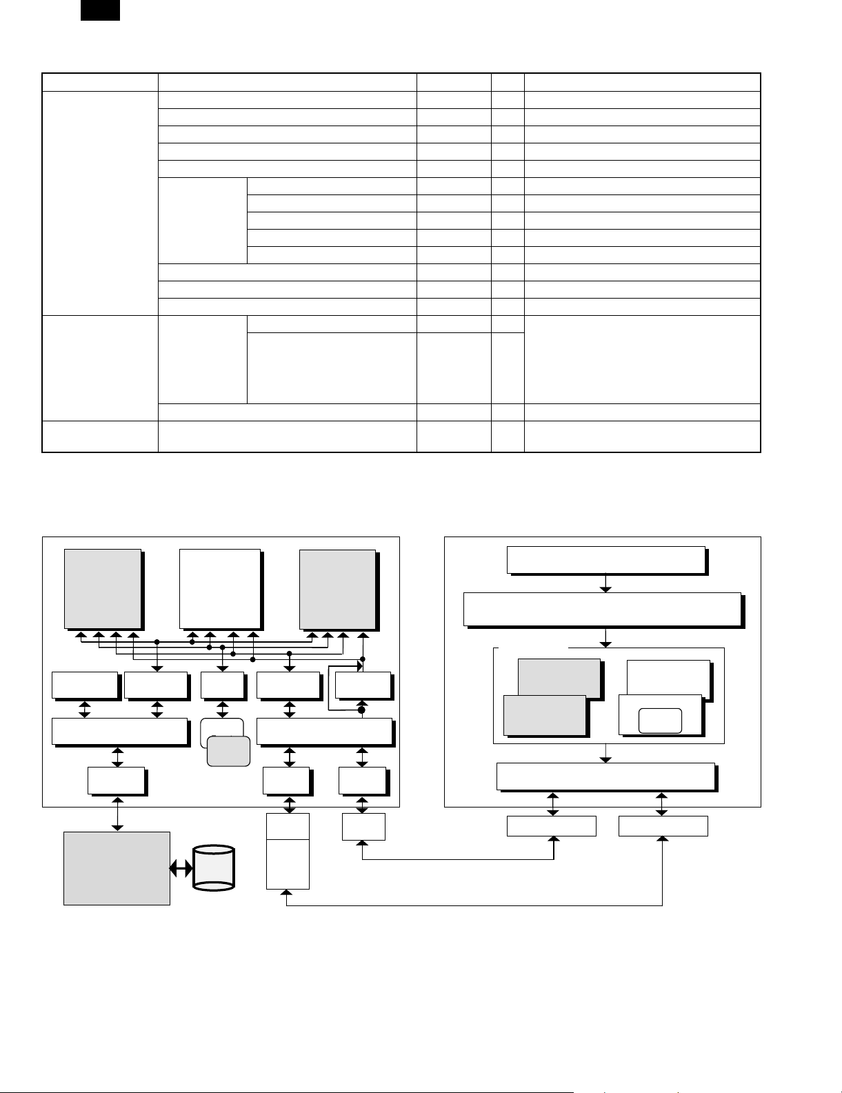
2. Software Configuration
ESC/P Super
ESC/P
(Japan only)
Front Panel
Control
Print Queue
Engine I/F Manager
SCSI-2 I/F
Driver
Print
Engine
Manager
PostScript L2
Font
Manager
Roman
Font
Kanji
(Japan only)
eRDH
PCL5e
(EX only)
PJL
Host I/O Manager
DPO
Driver
DPO
Port
NIC
Firmware
AUTO
Switching
1284
Driver
1284
Port
Win3.1x/Win95/WinNT4.0
Application
GDI (Graphic Module)
Printer Driver
PostScript
PCL
Print Spooler
1284 Port Ethernet Port
Others
PostScript
PPD
(Japan only)
1 – 2
Page 5

AR-PB2
Software on the PC side (Host: PC/AT, OS: Windows95/Windows
3.1)
Software on the PC/AT side is broadly divided into the following four
parts.
• Application
Application refers to software that computer users work with mainly to
create documents. Application software includes programs such as
MS Word and MS Excel.
• GDI(Graphic Module)
GDI refers to graphic module in the Windows system. GDI module
creates graphic data for each device (display monitor, printer, etc.)
according to drawing request from the application. Graphic data
created here is common in all Windows systems.
• Printer Driver
The printer driver converts graphic data created by a GDI driver into
printer-dependent print data. The AR-PB2 supports the following
three drivers: AR-PB2 customized PCL printer driver, customized
PostScript printer driver, and Adobe PostScript printer driver (PPD file
specific). The customized PCL printer driver creates PCL print data
from graphic data, while the PostScript driver and Adobe PostScript
printer driver (PPD file) create PS print data from graphic data.
• Print Spooler
Print spooler is a module for temporarily storing print data. It temporarily stores print data created by the printer driver on the HDD as
a spool file, and sends print data to the designated port in the order in
which the data is written onto the HDD.
Software(Firmware) in the Printer Controller
Software on the printer controller side is broadly divided into three
parts.
• Emulation Analysis
Emulation analysis involves analyzing print data and creating a print
image. The AR-PB2 is equipped with two emulations, PCL5e and
PostScript Level2.
Received data is analyzed using the emulation corresponding to print
data and is generat ed into the print image. For example, PCL5e data,
and PostScript data are respectively analyzed using PCL5e and PostScript Level2 emulation modes.
• Various Managers
– Host I/O Manager
Host I/O Manager controls I/O that is connected to PC. Host I/O
Manager supports automatic port selection mode and fixed port
mode. In the automatic port selection mode, when data is transmitted to a certain port, that port is automatically selected and
transmitted data is received through this port and processed. Data
transmitted to a port that is not selected is also received and
stored in the buffer, but will not be processed. Furthermore, automatic port selection mode consists of two modes. One mode
resumes automatic port selection after a certain interval once data
has been received (timeout); the other mode handles automatic
port selection between jobs.
In the fixed port mode, only data transmitted to the fixed port is
received, and data transmitted to other ports is never received.
– Engine I/F Manager
Engine I/F Manager controls command communication with the
print engine. The print image provided by Print Queue manager is
printed and output via command communication with the print engine.
– PJL
PJL (Printer Job Language) is a module for analyzing PJL data.
PJL functions as commands to specify various statuses of the print
job. PJL has the following three features.
1) Specify an emulation to be used for analyzing print data.
2) Establish the setting to be specified on the front panel.
3) Capture the status of the printer.
– AUTO Switching
AUTO Switching is a module for automatically matching print data
with its corresponding emulation based on data sensed when the
emulation to be used is not specified by a PJL command. AR-PB2
respectively support PCL 5e and PostScript.
AUTO Switching is enabled only when Auto is selected for the
emulation setting and the emulation to use for print data is not
specified by the PJL command at the beginning of a print job. In
other words, AUTO Switching is not handled during a print job.
Furthermore, when the emulation to be used is specified by the
PJL command or when the fixed emulation mode is selected, Auto
Switching is disabled.
– Print Queue Manager
Print Queue Manager is a module for providing necessary print
images created by each emulation and for deleting unnecessary
print images depending on the status of the print engine.
– Front Panel Control
Front Panel Control is a module for controlling the key operation
and the monitor display on the front panel. This module controls
the key operation and the monitor display in the printer setup
menu. Other settings (e.g. copier setting) and device status
monitor are controlled by the copier.
– Font Manager
Font Manager handles the resident fonts and the font types for
download. When a resident font is specified, a font image is
created based on resident font data. When a font is downloaded, a
font image is created based on downloadable font data.
• Drivers
– 1284 Driver
The 1284 Driver controls data communication via 1284 port. This
driver supports the P1284 Compatible mode and the Nibble
Device ID mode, however, does not support the Nibble mode,
ECP mode, and EPP mode.
– DPO Driver
The DPO Driver controls data communication via the DPO port for
DPI NIC(HBM NIC) connection.
– SCSI-2 I/F Driver
The SCSI-2 I/F Driver controls data communication for SCSI-2 I/F
that connects between the printer controller and the print engine.
The printer controller serves as the initiator, while the print engine
serves as the target.
All data, including print image data, various setting commands and
various information data needed for printing, are communicated
between the printer controller and the print engine via this SCSI-2
I/F.
Print Engine
As a copier feature, the print engine includes electronic sorting
(eRDH) so that it can support sort-output to the finisher. The reverse
order feature for face-up delivery (printing feature) is also handled by
this electronic sorting feature(eRDH). Additionally, as the electronic
sorting feature (eRDH) handles page ordering for the booklet feature
on the copier, the same feature on the printer is handled by the
electronic sorting feature (eRDH).
1 – 3
Page 6

AR-PB2
[2] SPECIFICATION
1. General Specification
A. PS Specification
Platform IBM PC/AT (or compatible)
Support OS
(Printer Drivers)
PDL
Emulation
CPU R4700 (64bit RISC / 150MHz)
Memory Standard 16MB
Resident Fonts For PS Type1: 35 fonts (Latin fonts)
Interface IEEE1284 parallel port: 1 port
Extend Interface 1 Network slot on printer board.
NIC Support DPI 1. 10Base-T/2 (AR-NC1D)
Port Selection Automatic Switch or
Emulation Switching Automatic Switch or
PnP Support Support on Windows95/98
2. Printing Function Specification
A. Outline
Output Quality Good Best Best
Print Speed Best Good Good
General Copies Yes Yes Yes
Paper
Input
Paper
Output
Custom
and PPD
Windows 3.1/WfW3.11 (No PPD)
Windows 95/98
Windows NT 4.0
PCL5e-compatible
PostScript Level 2-Compatible
Hex Dump
Maximum 80MB (32MB SIMM x 2 + 16MB)
Slot 2 Slots (16MB / 32MB SIMM can
be attached)
For PCL Intellifont : 35 fonts
TrueType : 10 fonts
Line Printer
Stroke Font
Port supports Compatible mode
(with PnP on Windows95/98).
NIC can be attached here.
Fix to each port
Fix to each emulation
Features PCL5e
Orientation Yes Yes Yes
Reverse Order Yes Yes Yes
Duplex Yes Yes Yes
Binding Edge Book Tablet Book Tablet Long / Short
2
N-up *
Booklet
Paper Size Yes Yes Yes
Custom Paper Size
Source Selection Yes Yes Yes
Transparency
inserts
Output Tray Selection Yes Yes Yes
Face Up/Down Yes Yes Yes
Staple Yes Yes Yes
Number 2/4/6/8/9/16 2/4/6/8/9/16 2/4*
Order N/A Fixed Fixed
Border N/A Yes Yes
Yes Yes N/A
Yes (1 size) Yes (1 size)
Blank Yes Yes N/A
Printed Yes Yes N/A
Windows
PostScript®
PPD
Yes (3
sizes)
Features PCL5e
Graphic Resolution Setting 600/300 600/300 600/300
Halftone Setting N/A Yes Yes
Graphics Mode Yes N/A N/A
Smoothing* Yes*
Toner save* Yes*
Negative Image N/A Yes Yes
Mirror Image
Zoom N/A N/A Yes
Fit to Page Yes Yes N/A
Font Font Setting Yes Yes Yes
Resident Font 35 PCL
Download Font
Watermark Print Yes Yes N/A
Edit Watermark Yes Yes N/A
1st Page Yes Yes N/A
Background Yes Yes N/A
Outline N/A Yes N/A
Others Configuration Setting Yes Yes Yes
Form Overlay Yes N/A N/A
N/A
10
TrueType
fonts
Bitmap
TrueType
Windows
PostScript®
1
Yes*
1
Yes*
Horizontal/
vertical
35 Type1 35 Type1
Bitmap
Type1
TrueType
1
1
PPD
1
Yes*
1
Yes*
Horizontal
Bitmap
Type1
TrueType
*1 The smoothing and toner save features are not available with the
AR-280/AR-285/AR-335 printers.
*2 Under Windows NT 4.0, the N-up feature is not available with the
PPD.
B. Details
(1) Printer Drivers
Supported Platforms and Languages are:
NO. PRINTER DRIVER WIN 3.1
1 Windows 3.1/95/98 PS
Windows 95/98 PPD
2 Windows NT PS
Windows NT PPD
3 Windows 3.1/95/98
PCL5e
4 Windows NT PCL5e X
(2) Printer Controller
a. Hardware
CPU: R4700 150MHz(64Bits RISC)
Peripheral ASIC: Galileo-Technology GT-64010A
DRAM Controller
DMA-4 ch (SCSI, P1284, IDE, Option I/F)
ROM:
Flash ROM 8 MB
(Boot (Sim)&Main Program/ Roman Font)*1
EEPROM 8 KB
RAM:
DRAM 16 MB (EDO)
SIMM 2 slots: 16/32 MB (Max. 32x2 + 16 = 80 MB)
Host I/O:
P1284 1ch: B connector (CL-CD1283)
16bits bus DMA
External I/O 1ch: DPO Type2 for DPI (HBM) NIC (optional)
Engine I/F:
SCSI-2 1ch: Asynchronous and Synchronous/16bits
bus DMA
WIN 95/
WIN 98
WIN NT
XX
X
XX
X
X
2 – 1
Page 7
AR-PB2
b. Firmware
Job Control: PJL(PJL is used in emulations other than
PCL5e.)
Emulation: PCL5e
PostScript
Emulation Switching AUTO, PS, PCL
Resident Fonts:
PCL5e
Roman 47 Fonts (HP5Si Typeface compatible)
PostScript
Roman 35 Fonts(Adobe PS Printer Typeface com-
patible)
Host I/O:
P1284
Compatible, Nibble for PnP
External I/O DPO Type2 for DPI (HBM) NIC
I/O Switching AUTO, P1284, NIC
Engine I/F:
SCSI-2 Asynchronous and Synchronous /DMA transfer
c. Emulation
Automatic (PCL ↔ PS)
PCL (fixed)
PostScript (fixed)
Emulation switching is performed in the following manner.
PJL Command
for Specifying
an Emulation
No OK Uses the
Yes Yes Uses the emulation
Specified
Emulation
Automatic
Sensing
NG Uses PCL
specified.
No Uses PCL Uses a default
Emulation Setting
Automatic Fixed
emulation
automatically
selected.
Uses a default
emulation.
Uses the
emulation
specified.
emulation.
In the automatic emulation sensing mode, for print data without the
PJL command, the emulation is automatically switched either to PostScript, PCL5e based on data sensed. In other words, automatic
emulation sensing (switching) is available only between PostScript
and PCL5e. For print data with the PJL command, the emulation is
automatically switched to the specified one without sensing the data.
When print data without the PJL command fails to be sensed, or
when the print data is given the PJL command but the specified
emulation is not present, the data is handled in the PCL emulation.
In the fixed emulation mode, for print data without the PJL command,
the fixed emulation is used to handle the print data. Print data with
the PJL command is switched to the specified emulation. When print
data is given the PJL command but the specified emulation is not
present, the data is processed by the default emulation.
The PJL Enter command specifies PostScript and PCL5e.
(3) Engine Spec.
Maximum
Paper Size
Print
Resolution
Smoothing Yes
Engine Speed 28ppm: AR-280/285
Print Speed Supports the maximum print speed when
Input Paper
Trays
Support Paper
Sizes
Output Devices 2 Exit Trays Top / 2nd Tray
Electric
Collation
Duplex Printing Yes
∗1: AR-280/285/335 does not support Smoothing.
A3, 11" x 17"
600 dpi
1
∗
33ppm: AR-335
(A4 / 8.5" x 11 continuous printing of same page)
printing the same print data continuously.
Standard: Tray 1 / Tray 2 / Bypass Tray
Option: Tray 3 / Tray 4 / LCC
A6, A5, A4, A3, B5, B4, Japanese Postcard
(148x1 00 mm) , 5. 5" x 8.5 "( Inv oi ce) , 7. 25 " x
10.5"(Executive), 8.5" x 11"(Letter), 8.5" x
13"( Fool s ca p), 8.5" x 14" (Le ga l) , 11" x 17" ( Le dg er)
Custom (Max;297 x 432_Min;100 x 148)
2Tray Finisher: Top / Offset Tray
3Tray Finisher: Top / 2nd / Offset Tray
Support By E-RDH
(software collation will not be supported.)
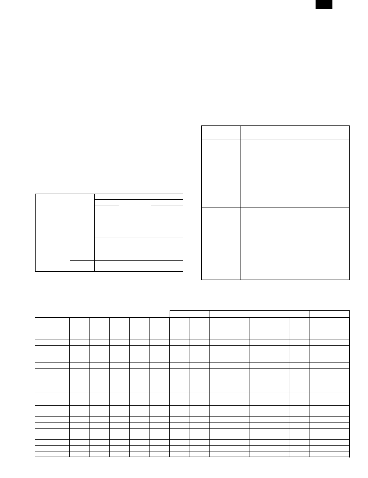
(4) Paper Handling Specicification
a. Outline
Exit Tray 3tray FIN. 2tray FIN.
Name
A6R Yes N/A N/A N/A N/A Yes N/A Yes N/A N/A N/A N/A Yes N/A
5.5 × 8.5 in. Yes Yes N/A N/A N/A Yes Yes Yes Yes N/A N/A N/A Yes N/A
A5 Yes Yes N/A N/A Yes Yes Yes Yes Yes N/A N/A N/A Yes N/A
B5 Yes Yes Yes Yes Yes Yes Yes Yes Yes Yes Yes Yes Yes Yes
B5R Yes Yes Yes N/A Yes Yes Yes Yes Yes Yes Yes N/A Yes N/A
Executive-R Yes Yes N/A N/A Yes Yes Yes Yes Yes Yes Yes N/A Yes N/A
Letter Yes Yes Yes Yes Yes Yes Yes Yes Yes Yes Yes Yes Yes Yes
Letter-R Yes Yes Yes N/A Yes Yes Yes Yes Yes Yes Yes Yes Yes N/A
A4 Yes Yes
A4-R Yes Yes
Legal Yes
Fools Cap 8.5 ×
13 in
B4 Yes Yes Yes N/A Yes Yes Yes Yes Yes Yes Yes Yes Yes N/A
A3 Yes Yes Yes N/A Yes Yes Yes Yes Yes Yes Yes Yes Yes N/A
11 × 17 in Yes Yes Yes N/A Yes Yes Yes Yes Yes Yes Yes Yes Yes N/A
JPN postcard Yes N/A N/A N/A N/A Yes N/A Yes N/A N/A N/A N/A Yes N/A
Transparency Yes N/A N/A N/A N/A Yes N/A Yes N/A N/A N/A N/A Yes N/A
Heavy stock Yes N/A N/A N/A N/A Yes N/A Yes N/A Yes N/A Yes Yes N/A
Label Yes N/A N/A N/A N/A Yes N/A Yes N/A N/A N/A N/A Yes N/A
Multi-
Bypass
Tray1,2
Tray
Yes Yes
Yes Yes Yes N/A Yes Yes Yes Yes Yes Yes Yes Yes Yes N/A
Desk
Tray
Yes
Yes
LCC Duplex
Yes
N/A Yes Yes Yes Yes Yes Yes Yes Yes Yes N/A
N/A
Yes
Yes
Exit
Face-up
Tray1
Yes Yes Yes Yes Yes Yes Yes Yes Yes
Yes Yes Yes Yes Yes Yes Yes Yes N/A
Exit
Face-up
Tray2
Tray1
Face-up
Tray2
Face-up
Tray3
Face-up
Tray
1,2,3
Facedown
Tray3
Face-up
Staple
Tray1
Face-up
2 – 2
Tray2
Face-
up/down
Staple
Page 8
AR-PB2
b. Details
<1> Paper Input
Tray name Paper Size Capacity (Maximum Sheets) Comment
Standard Bypass Tray (BT) 11" x 17", A3, B4, Foolscap (8.5" x
Tray1 11" x 17", A3, B4, Foolscap (8.5" x
Tray2 ↑↑↑
OPTIONAL Tray3 11" x 17", A3, B4, Foolscap (8.5" x
Tray4 ↑↑↑
Tray5 ↑↑↑
LCC A4, Ltr, B5 3000 (80g/m2)
<2> Duplex Unit (ADU)
Tray name Paper Size Capacity Comment
Optional Duplex module 11"x17", A3, B4,
<3> Paper Output
Output
Device
Standard 1 Tray Exit — N/A Face-up All supported sizes N/A 250
2 Tray Exit
Unit
(Some are
optional)
Optional 2 Tray
Finisher
3 Tray
Finisher
N/A - Stapling is disabled. Yes - Stapling is enabled and there is the stapling selection. No - Stapling is enabled but there is no stapling selection.
Use of Different Paper Cross sizes within one job (multiple sizes of paper, the same size but in a different direction) disables the staple feature.
Tray Name
(Paper
Destination)
Tray 1 N/A Face-up All supported sizes N/A 250
Tray 2 N/A Face-up 11"x17", A3, B4, Foolscap, Legal, A4,
Tray1 N/A Face-up All supported sizes N/A 250
Tray2 Yes Face-up Ltr, A4, B5 No 750
Tray1 N/A Face-up All supported sizes N/A 500
Tray2 N/A Face-up 11" x 17", A3, B4, Foolscap, Legal,
Tray3 Yes Face-up 11" x 17", A3, B4, Foolscap, Legal,
13"), Legal, A4, A4-R, Ltr, Ltr-R,
Exec-R, B5, B5-R, A5, 5.5" x 8.5",
A6R, JPN postcard
13"), Legal, A4, A4-R, Ltr, Ltr-R,
Exec-R, B5, B5-R, A5, 5.5" x 8.5"
13"), Legal, A4, A4-R, Ltr, Ltr-R, B5,
B5-R
Foolscap(8.5"x13"), Legal, A4,
A4-R, Ltr, Ltr-R, Exec-R, B5, B5-R,
A5
Offset Facing Paper size Staple* Capacity
A4-R, Ltr, Ltr-R, B5, B5-R, A5, 5.5" x
8.5"
Face-down Ltr, A4, B5 No 750
A4, A4-R, Ltr, Ltr-R, Exec-R, B5,
B5R, A5, 5.5" x 8.5"
Face-down 11" x 17", A3, B4, Foolscap, Legal,
A4, A4-R, Ltr, Ltr-R, Exec-R, B5, B5R
A4, A4-R, Ltr, Ltr-R, Exec-R, B5, B5R
11"x17", A3, B4, Foolscap, Legal,
A4-R, Ltr-R
A4, Ltr, B5 1500
Face-down 11" x 17", A3, B4, Foolscap, Legal,
A4, A4-R, Ltr, Ltr-R, Exec-R, B5, B5R
50 (80g/m2) Tray capacity is calculated based on
550 (64g/m2) (Domestic)
500 (80g/m2) (Overseas)
550 (64g/m2) (Domestic) 500 (80g/m2) (Overseas)
Not limited No limitation because of Trayless
the paper weight of 80g/m2.
Duplex.
Comment
(Sheets)
[80g/m2]
N/A 100
Yes 750
Staple: 30
N/A 500
No 1500
Yes 1500 Staple: 253 types
Staple: 50
No 1500
1 type of Staple
Location.
The maximum
number of sheets
available for
Staple is 30.
of Staple
LocationsRThe
Maximum number
of sheets
available for
Staple is 25/50.
2 – 3
Page 9
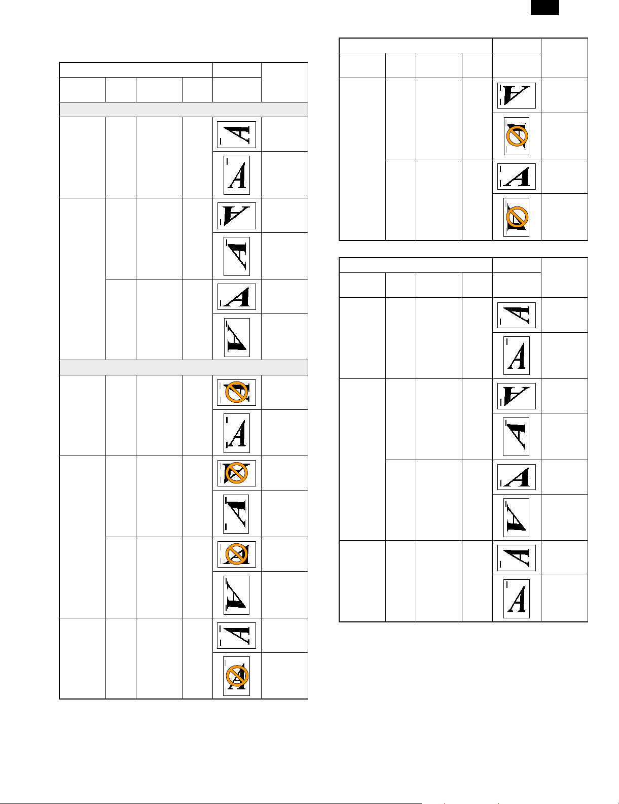
AR-PB2
(PS PPD Driver)
Simplex 1/2 Staple
Driver Output
Orientation
Portrait N/A 1 Pos No Short
Landscape No 1 Pos No Short
Land
180
Yes 1Pos No Short
Staple Dup.
Pattern
(← Feed)
Paper Dir.
Edge Feed
Long
Edge Feed
Edge Feed
Long
Edge Feed
Edge Feed
Long
Edge Feed
Driver Output
Orientation
Landscape No 2
Duplex 1/2 Staple
Orientation
Portrait N/A 1 Pos Long Short
Land
180
Yes 2
Land
180
Staple Dup.
No Short
Pos-Short
No Short
Pos-Short
Driver Output
Staple Dup.
Pattern
(← Feed)
Pattern
(← Feed)
Paper Dir.
Edge Feed
Long
Edge Feed
Edge Feed
Long
Edge Feed
Paper Dir.
Edge Feed
Long
Edge Feed
Portrait N/A 2
Pos-Long
Landscape No 2
Pos-Long
Yes 2
Pos-Long
Portrait N/A 2
Pos-Short
No Short
Edge Feed
Long
Edge Feed
No Short
Edge Feed
Long
Edge Feed
No Short
Edge Feed
Long
Edge Feed
No Short
Edge Feed
Long
Edge Feed
Landscape No 1 Pos Long Short
Edge Feed
Long
Edge Feed
Yes 1 Pos Long Short
Edge Feed
Long
Edge Feed
Portrait N/A 1 Pos Short Short
Edge Feed
Long
Edge Feed
2 – 4
Page 10

AR-PB2
Driver Output
Orientation
Landscape No 1 Pos Short Short
Portrait N/A 2
Landscape No 2
Land
180
Yes 1 Pos Short Short
Staple Dup.
Long Short
Pos-Long
Long Short
Pos-Long
Pattern
(← Feed)
Paper Dir.
Edge Feed
Long
Edge Feed
Edge Feed
Long
Edge Feed
Edge Feed
Long
Edge Feed
Edge Feed
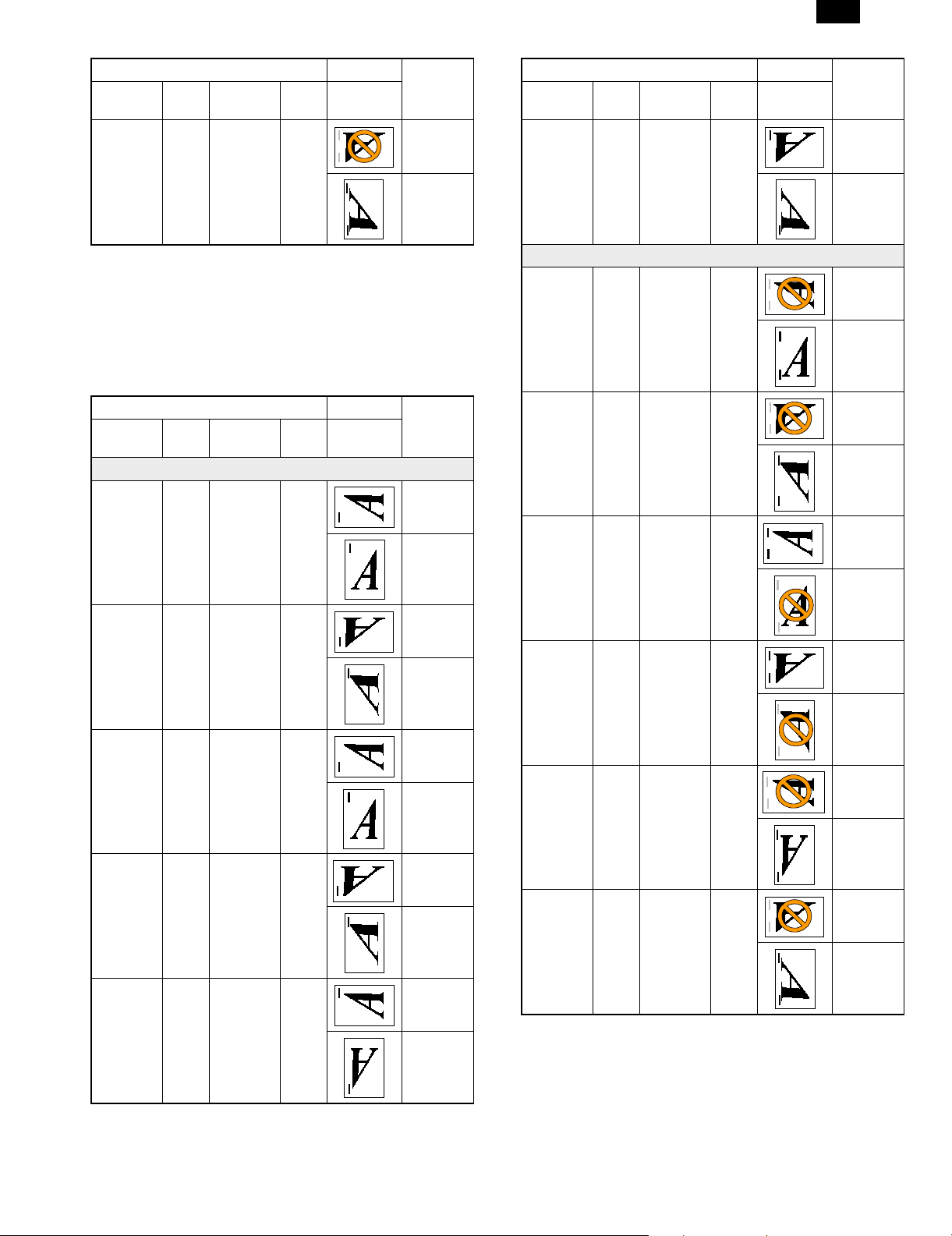
(PS Driver)
Simplex 1/2 Staple
Driver Output
Orientation Staple Dup. Right
1 Position
Portrait 1 Pos No No Short
Landscape 1 Pos No No Short
Portrait 1 Pos No Yes Short
Pattern(←
Feed)
Paper Dir.
Edge Feed
Long
Edge Feed
Edge Feed
Long
Edge Feed
Edge Feed
Long
Edge Feed
Yes 2
Pos-Long
Portrait N/A 2
Pos-Short
Landscape No 2
Pos-Short
Yes 2
Pos-Short
Long
Edge Feed
Long Short
Edge Feed
Long
Edge Feed
Short Short
Edge Feed
Long
Edge Feed
Short Short
Edge Feed
Long
Edge Feed
Short Short
Edge Feed
Long
Edge Feed
Landscape 1 Pos No Yes Short
Edge Feed
Long
Edge Feed
2 Position
Portrait 2 Pos No No Short
Edge Feed
Long
Edge Feed
Landscape 2 Pos No No Short
Edge Feed
Long
Edge Feed
Portrait 2 Pos No Yes Short
Edge Feed
Long
Edge Feed
2 – 5
Page 11
AR-PB2
Driver Output
Orientation Staple Dup. Right
Landscape 2 Pos No Yes Short
Note: PS Custom Driver sends BINDING command in accord-
ance with the feed direction of each paper.
Long Edge Feed: Letter, Invoice, A4, A5, B5
Short Edge Feed: Ledger, Legal, Foolscap, Executive,
A3, A6, B4
Therefore Letter-R, A4-R, and B5-R cannot staple 2position by PS
Custom Driver.
Duplex 1/2 Staple
Driver Output
Orientation Staple Dup. Right
1 Position
Portrait 1 Pos Book No Short
Landscape 1 Pos Book No Short
Portrait 1 Pos Tablet No Short
Landscape 1 Pos Tablet No Short
Portrait 1 Pos Book Yes Short
Pattern(←
Feed)
Pattern
(← Feed)
Paper Dir.
Edge Feed
Long
Edge Feed
Paper Dir.
Edge Feed
Long
Edge Feed
Edge Feed
Long
Edge Feed
Edge Feed
Long
Edge Feed
Edge Feed
Long
Edge Feed
Edge Feed
Driver Output
Orientation Staple Dup. Right
Landscape 1 Pos Book Yes Short
2 Position
Portrait 2 Pos Book No Short
Landscape 2 Pos Book No Short
Portrait 2 Pos Tablet No Short
Landscape 2 Pos Tablet No Short
Portrait 2 Pos Book Yes Short
Landscape 2 Pos Book Yes Short
Pattern
(← Feed)
Paper Dir.
Edge Feed
Long
Edge Feed
Edge Feed
Long
Edge Feed
Edge Feed
Long
Edge Feed
Edge Feed
Long
Edge Feed
Edge Feed
Long
Edge Feed
Edge Feed
Long
Edge Feed
Edge Feed
Long
Edge Feed
Long
Edge Feed
2 – 6
Page 12
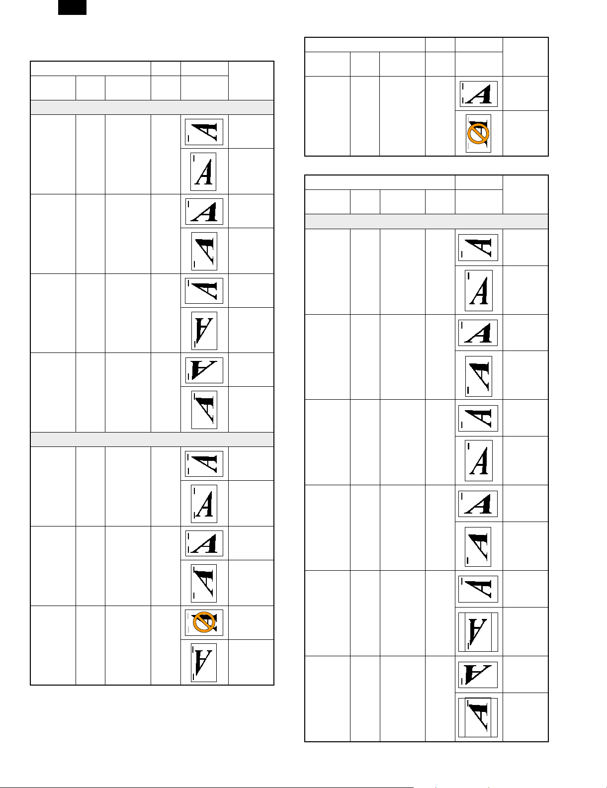
AR-PB2
(PCL Driver )
Simplex 1/2 Staple
Driver Output
Orientation Staple Dup. Right
1 Position
Portrait 1 Pos No No Short
Landscape 1 Pos No No Short
Portrait 1 Pos No Yes Short
Pattern
(← Feed)
Paper Dir.
Edge Feed
Long
Edge Feed
Edge Feed
Long
Edge Feed
Edge Feed
Long
Edge Feed
Driver Output
Orientation Staple Dup. Right
Landscape 2 Pos No Yes Short
Duplex 1/2 Staple
Driver Output
Orientation Staple Dup. Right
1 Position
Portrait 1 Pos Book No Short
Landscape 1 Pos Book No Short
Pattern
(← Feed)
Pattern
(← Feed)
Paper Dir.
Edge Feed
Long
Edge Feed
Paper Dir.
Edge Feed
Long
Edge Feed
Edge Feed
Landscape 1 Pos No Yes Short
Edge Feed
Long
Edge Feed
2 Position
Portrait 2 Pos No No Short
Edge Feed
Long
Edge Feed
Landscape 2 Pos No No Short
Edge Feed
Long
Edge Feed
Portrait 2 Pos No Yes Short
Edge Feed
Long
Edge Feed
Portrait 1 Pos Tablet No Short
Edge Feed
Long
Edge Feed
Landscape 1 Pos Tablet No Short
Edge Feed
Long
Edge Feed
Portrait 1 Pos Book Yes Short
Edge Feed
Long
Edge Feed
Long
Edge Feed
Landscape 1 Pos Book Yes Short
Edge Feed
Long
Edge Feed
2 – 7
Page 13
AR-PB2
Driver Output
Orientation Staple Dup. Right
Pattern
(← Feed)
Paper Dir.
2 Position
Portrait 2 Pos Book No Short
Edge Feed
Long
Edge Feed
Landscape 2 Pos Book No Short
Edge Feed
Long
Edge Feed
Portrait 2 Pos Tablet No Short
Edge Feed
Long
Edge Feed
Landscape 2 Pos Tablet No Short
Edge Feed
Refer to Front panel specification
Des. AB series Inch series
Name
JPN post N/A N/A N/A N/A N/A N/A N/A N/A
A6R Yes Key OP N/A N/A Yes N/A N/A N/A
5.5 × 8.5 in. PRT
A5 Yes Yes N/A N/A PRT
B5 Yes Yes Yes Yes Yes Key OP Key OP Yes
B5R PRT
Executive-R Yes Key OP N/A N/A Yes Key OP N/A N/A
Letter Yes Yes Yes Yes Yes Yes Yes
Letter-R PRT
A4 Yes Yes Yes Yes Yes Yes Yes Yes
A4-R Yes Yes Yes N/A PRT
Legal Yes Key OP Key OP N/A Yes Yes Yes N/A
FoolsCap
8.5 × 13
B4 Yes Yes Yes N/A Yes Key OP Key OP N/A
A3 Yes Yes Yes N/A Yes Key OP Key OP N/A
11 × 17 in. Yes Key OP Key OP N/A Yes Yes Yes N/A
Bypass
Tray1,2 Desk LCC
Tray
Key OP N/A N/A Yes Yes N/A N/A
Key OP
Key OP Key OP N/A PRT
Key OP
Key OP Key OP N/A Yes Yes Yes N/A
Key OP
Sim
Key OP Key OP N/A Sim
(Legal)
Bypass
Tray1,2 Desk LCC
Tray
Key OP N/A N/A
Key OP
Key OP Key OP N/A
Key OP
Key OP Key OP N/A
Key OP
(Legal)
Yes Yes N/A
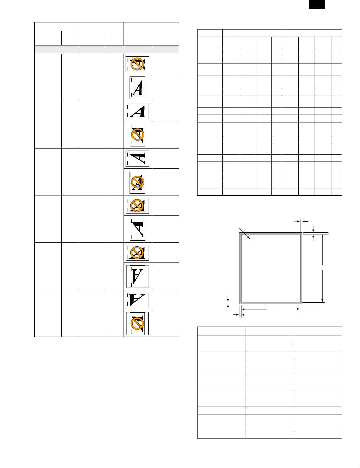
(5) Print Area
Yes
Long
Edge Feed
Portrait 2 Pos Book Yes Short
Edge Feed
Long
Edge Feed
Landscape 2 Pos Book Yes Short
Edge Feed
Long
Edge Feed
<4> Detactable Media Sizes in the Bypass Tray
Yes: detection: Yes
Key OP: by the key operator program
No: detection: No (The engine treats this as an
extra)
N/A: Not applicable
PRT Key OP: By the printer key operator program
Sim(legal): Foolscap size is detected at the Legal size
position by Simulation.
The size detection- "Off" mode will be added in the printer key
operator program.
2.7mm (7/64")
Printable area
2.7mm (7/64")
X
2.7mm (7/64")
Paper size X Y
A3 6912 9824
B4 5952 8480
A4 6912 4864
B5 5952 4192
A5 4864 3392
A6 2368 3392
Ledger 6464 10080
Letter 6464 4992
Legal 4992 8288
Invoice 4992 3168
Executive 4224 6176
Foolscap 4992 7680
Japanese Postcard 2240 3392
(dots in 600 dpi)
2.7mm (7/64")
Y
2 – 8
Page 14
AR-PB2
(6) Font
a. Resident Font
Resident Fonts
Emulation Resident Font
PCL5e Roman 45 Fonts (Bitstream)
1 Font-Stroke(Bitstream)
1 Font-Bitmap(Bitstream)
PostScript Roman 35 Fonts (Bitstream)
1) PCL5e Roman fonts
Number of fonts: 47
Font format: (45 fonts), Stroke(1 font), Bitmap(1 font)
Font data size: Approx. 1.9MB
Font supplier: Bitstream
Font No. Font name
1 Courier Roman SWC
2 Dutch™ 801 SWC
3 Dutch 801 Bold SWC
4 Dutch 801 Italic SWC
5 Dutch 801 Bold Italic SWC
6 Zapf Humanist 601 SWC
7 Zapf Humanist 601 Bold SWC
8 Zapf Humanist 601 Italic SWC
9 Zapf Humanist 601 Bold Italic SWC
10 Ribbon 131 SWC
11 Clarendon Condensed SWC
12 Swiss™ 742 SWC
13 Swiss 742 Bold SWC
14 Swiss 742 Italic SWC
15 Swiss 742 Bold Italic SWC
16 Swiss 742 Condensed SWC
17 Swiss 742 Bold Condensed SWC
18 Swiss 742 Condensed Italic SWC
19 Swiss 742 Bold Condensed Italic SWC
20 Incised 901 SWC
21 Incised 901 Bold SWC
22 Incised 901 Italic SWC
23 Original Garamond SWC
24 Original Garamond Bold SWC
25 Original Garamond Italic SWC
26 Original Garamond Bold Italic SWC
27 Audrey Two SWC
28 Flareserif 821 SWC
29 Flareserif 821 Extra Bold SWC
30 Swiss 721 SWM
31 Swiss 721 Bold SWM
32 Swiss 721 Oblique SWM
33 Swiss 721 Bold Oblique SWM
34 Dutch 801 SWM
35 Dutch 801 Bold SWM
36 Dutch 801 Italic SWM
Font No. Font name
37 Dutch 801 Bold Italic SWM
38 Symbol SWA
39 Wingbats SWM
40 Courier Bold SWC
41 Courier Italic SWC
42 Courier Bold Italic SWC
43 Letter Gothic SWC
44 Letter Gothic Bold SWC
45 Letter Gothic Italic SWC
46 HP-GL stroke
47 Line printer
2) PS2 Roman fonts
Number of fonts: 35
Font format: (All of the 35 fonts)
Font data size: Approx. 0.9MB
Font supplier: Bitstream
Font name
ITC Avant Garde Gothic® Book
ITC Avant Garde Gothic Book Oblique
ITC Avant Garde Gothic
ITC Avant Garde Gothic Demi Oblique
ITC Bookman® Demi
ITC Bookman Demi Italic
ITC Bookman Light
ITC Bookman Light Italic
810 Courier®
810 Courier Bold
810 Courier Bold Italic
810 Courier Italic
Swiss( 721 Normal
Swiss 721 Bold
Swiss 721 Bold Oblique
Swiss 721 Oblique
Swiss 721 Narrow
Swiss 721 Narrow Bold
Swiss 721 Narrow Bold Oblique
Swiss 721 Narrow Oblique
Century Schoolbook Bold
Century Schoolbook Bold Italic
Century Schoolbook Italic
Century Schoolbook Roman
Zapf Calligraphic 801
Zapf Calligraphic 801 Bold
Zapf Calligraphic 801 Bold Italic
Zapf Calligraphic 801 Italic
Symbol Set
Dutch( 801 Bold
Dutch 801 Bold Italic
Dutch 801 Italic
Dutch 801 Normal
ITC Zapf Chancery® Medium Italic
ITC Zapf Dingbats®
2 – 9
Page 15
b. Download Fonts
Data formats of download fonts in each emulation are in the table
below.
Emulation Download Font
PCL5e Roman Bitmap
Kanji N/A
PostScript Roman Bitmap
Kanji N/A
TrueType
Intellifont
Type 1
Type 42
(7) Interface Specification
The printing system supports IEEE 1284 compliant connections
Properties
IEEE 1284 • IEEE 1284 Compliant
• Compatible
• Connector: 1 (Type B)
(8) Network Specification
Interface
DPI_NIC 10BaseT/2 NetWare,
SupportOSSupport
Protocol
IPX/SPX,
Windows
NT
TCP/IP,
EtherTalk,
Peer to
Peer (IPX
/ SPX)
Area
JPN, North
America
(USA/CANADA),
Europe, EX
AR-PB2
2 – 10
Page 16
AR-PB2
[3] SETUP
1. Parts list
Before installing the printer kit, check that all the following items are prepared.
Be careful that the necessary parts depend on the environment of the copier (model and unit installation).
Part name Model Q’ty Note
Accessories SCSI cable 1
Wire saddle 1
Band 1
Printer box installing screw 5
Printer control PWB 1 With frame
Printer driver Windows 95 PCL5E Driver (FD) 1
Windows NT PCL5E Driver (FD) 1
Windows 95 PS Driver (FD) 1
Windows NT PS Driver (FD) 1
Installation manual 1
Operation Manual 1
Label 1 Only for Sweden and Norway
Option Expansion board AR-EB1 1 The expansion board is necessary to install
SIMM memory 16MB ED0 type/Without parity/70ns or above
32MB
Network card AR-NC1D 1 10BASE T/10BASE 2
Separate purchase
(User purchase)
Printer (parallel) cable Necessary when the copier is used as a
the printer kit to the AR-S280.
The copier ICU PWB requires the total
memory of 16MB(20MB) or more.
The printer control PWB has two expansion
slots to which 16MB or 32MB memory can
be additionally installed. (16MB onboard)
stand-alone machine.
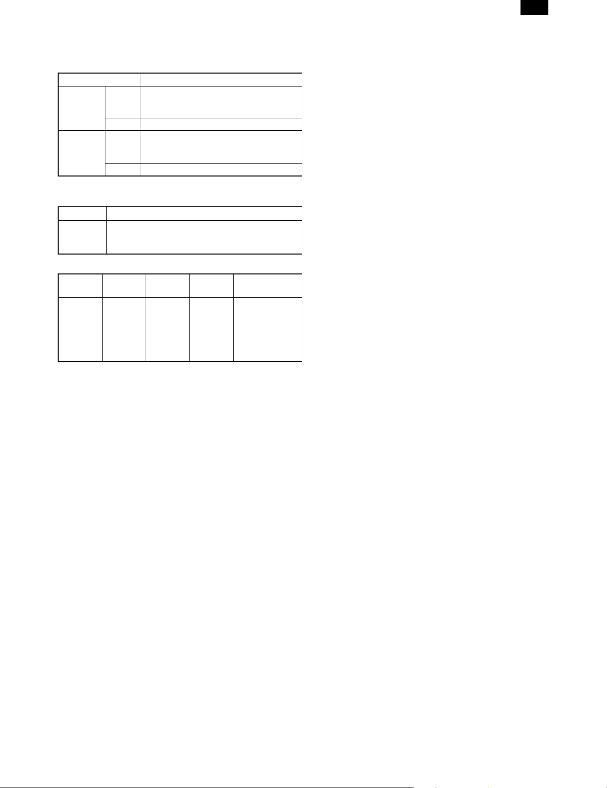
2. Preliminary work
If the version of the three kinds of flash memory installed to the copier
is older than the following, upgrade is required.
Check version number, and perform the upgrade if necessary. (For
the procedure, refer to the Technical Report.)
Flash memory version
Operation PWB 2.xx
ICU PWB 2.xx
PCU PWB 2.xx
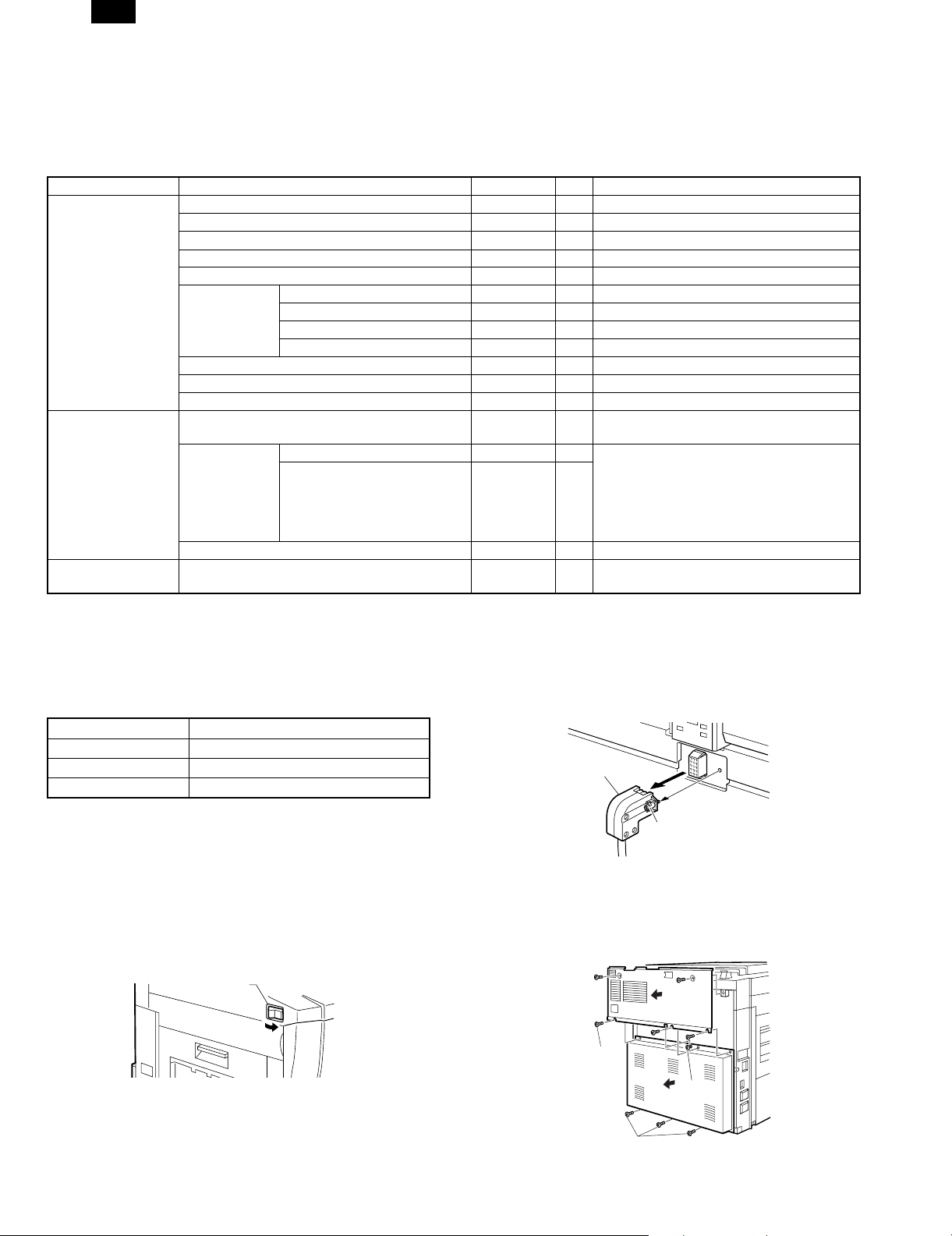
3. Hardware setup
A. Common work
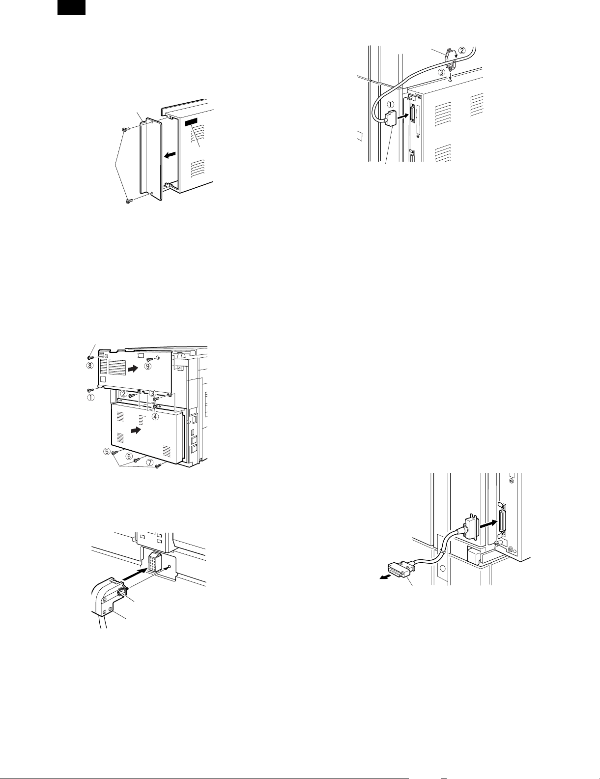
(1) Printer unit installation
1) Turn "OFF" the main switch located on the left-hand side on the
main copier unit.
Next, unplug the power plug of the main copier unit from the
outlet.
Main switch
"OFF"
2) Removing the rear cover of the main copier unit.
If equipped with the RADF/ADF/SPF, loosen the securing screws
which the hold the RADF/ADF/SPF connector and remove the
connector from the main copier unit.
Connector
Screw
Remove the five securing screws which hold the rear cover of
main copier unit, and remove the rear cover.
Next, loosen the upper central one of four securing screws which
hold the rear lower cover, then remove the rest three screws.
Remove the rear lower cover.
Rear cover
Securing
screw
Loosen
Rear lower cover
3 – 1
Securing screws
Page 17
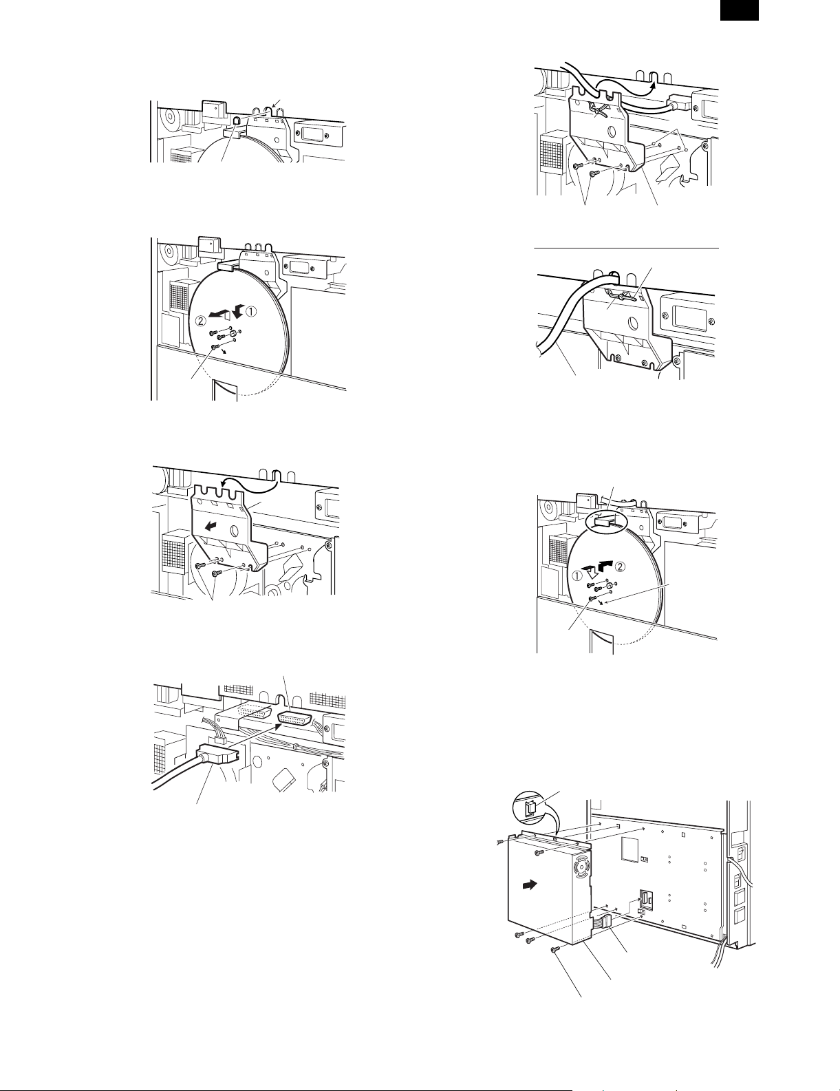
3) Cut out the central one of three notches of upper rear cover with a
nipper.
Notches
AR-PB2
A notch
4) Remove the three securing screws which hold the flywheel and
remove the flywheel.
Flywheel
Securing
screw
5) Remove the two securing screws which hold the shield line guide
to the main drive frame and remove the shield line guide.
Shield line
guide
Binding
band
Securing screws
Binding
band
Printer relay cable
Cut away the surplus
Ribs
Shield line guide
8) Reinstall the flywheel (which was removed in the step 4) onto the
main drive shaft while slipping inside the exterior. Use the three
securing screws to secure it.
Make sure the arrow mark on flywheel faces toward you.
Caution
Securing screws
6) Plug the printer relay cable connector into the most right hand port
on the ICU board.
Port on the ICU board
Printer relay cable
7) Place the printer relay cable into the central notch of shield line
guide (the location with a letter P) and attach it temporarily with a
binding band as shown in the illustration.
Next, insert the two ribs on the main drive frame through the
positioning holes of shield line guide, then use the two securing
screws to secure it.
Place the printer relay cable as shown in the illustration, then
tighten the binding band and cut away the excess.
Flywheel
Engraved
arrow mark
Securing
screw
<Caution> Do not turn the flywheel with hands after installation
since it may cause damage to the gears.
9) Connect the power connector of printer box unit to the power
supply port on the main copier unit, then attach the printer box unit
on the holes of F/P box mounting plate using the hooks.
Using the 5 print er bo x securi ng screw s, at tach the p rinter box to
the mounting plate.
Hook
Power connector
3 – 2
Printer box unit
Printer box securing screw
Page 18
AR-PB2
10) Remove the securing screws holding the P side OP cover in the
rear lower cover which was removed in the step 2, then remove
the P side OP cover.
Next, paste an attached label at the position only for Sweden
and Norway as shown in the illustration.
P side OP cover
Label
Securing
screws
11) Hook the rear lower cover on the securing screw 4 which was
loosened in the step 1 as shown in the illustration.
Next, tighten the securing screws 1, 2 and 3 temporarily,
which were removed in the step 2 and tighten the securing
screw 4 which was loosened, tighten the securing screws 5,
6 and 7.
Reinstall the rear cover tighten (which was removed in the step
2) to the original position by putting it onto the securing screws
1, 2 and 3 which temporarily secure the rear cover, then
tighten the securing screws 1, 1 and 3 after tightening the
securing screws 8 and 9.
Securing screw
Rear cover
Wire saddle
Printer relay cable
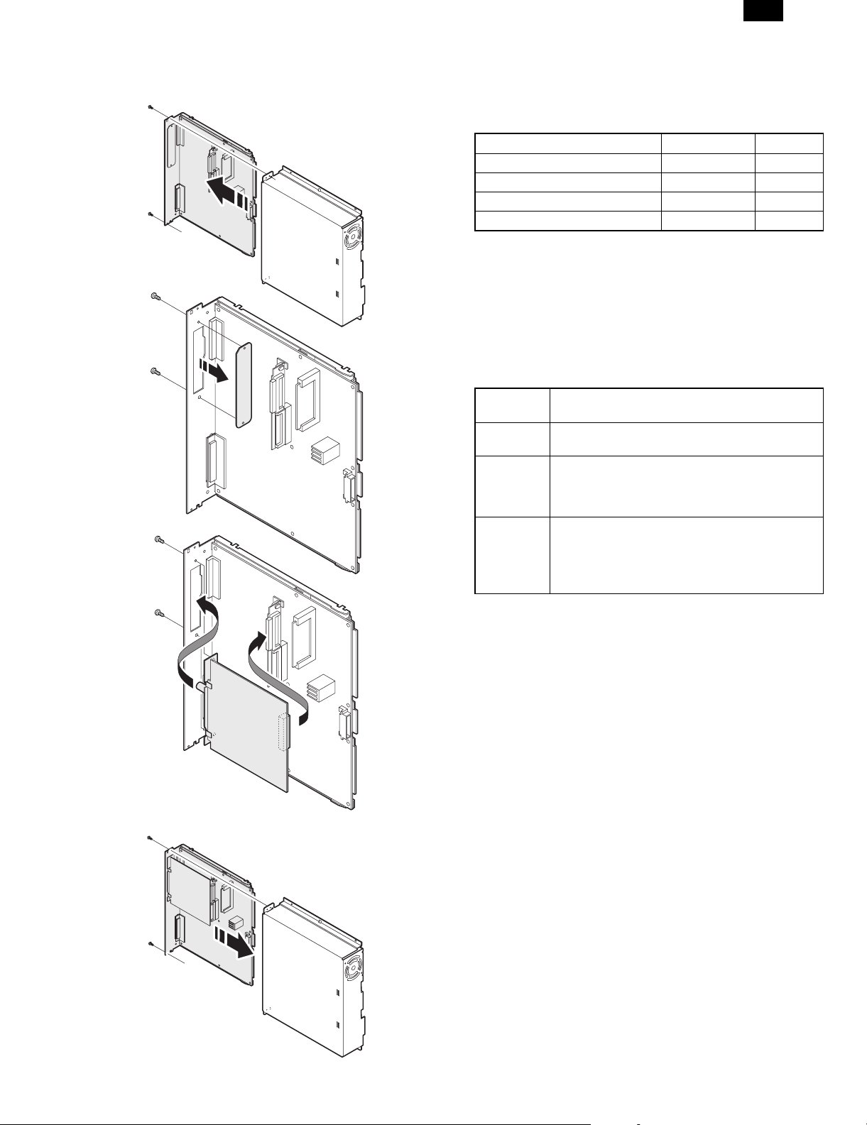
(2) Expansion memory installation
a. Memory expansion in the printer control PWB
Normally there is no need for memory expansion. However,
memory expansion will increase the printer performance.
When printing graphics or complex data, memory expansion will
increase printing speed.
Memory of 16MB or 32MB can be installed to the two slots. (16MB
onboard)
Different capacity of memory can be installed to the two slots.
The total memory after expansion may be 32, 48, 64, or 80MB.
After the above procedure, select VM Option menu and set the
total memory capacity.
b. ICU PWB memory expansion
The copier ICU PWB requires total memory capacity of 16 (20)MB
or more.
Memory of 16MB or 32MB can be installed to the two slots. (4MB
onboard)
Different capacity of memory can be installed to the two slots.
Loosened
screw
Rear lower
cover
Securing
screws
12) If equipped with the RADF/ADF/SPF, reinstall the connector that
was removed in the step 2 to the original position on the main
copier unit, then secure with screws attached to the connector.
Screw
Connector
1 Connect the printer relay cable to the connector of printer
box.
2 Attach the packaged wire saddle to the printer relay cable.
3 Insert and attach the wire saddle at the position of rear lower
cover as shown in the illustration.
B. Stand-alone environment (Printer (parallel)
cable connection)
Plug the connector of the Centronics cable (sold separately) into the
Centronics port on the printer box base.Plug the other connector into
the laser printer port on a personal computer.
Connector going to the
laser printer port on the
personal computer
Centronics cable
(sold separately)
3 – 3
Page 19
AR-PB2
C. Network environment (Network card installation)
1) Insert the network card into the network card slot on the printer
control PWB. and fix it with screws.
4. Setup on the copier side
A. Setup by simulation
Setup the following items. For parallel I/F, setup, if there is no trouble
in operations, there is no need to change any settings.
Content Simulation No. Set value
System configuration setup 26-44 1
Print counter count mode setup 26-05
Parallel I/F timing adjustment 67-03
Parallel I/F select IN signal timing 67-11
B. Setup by key operator program
Refer to the section of the key operator program and make setting
according to the user environment.
5. Software installation and setup
Checking the Hardware and Software Requirements
You will need the following hardware and software in order to install
the printer driver.
Computer
Type
Operating
System
CPU Windows 3.1/Windows 95: 486SX or better
RAM Windows 3.1/
IBM PC/AT or compatible computer equipped with
a bi-directional parallel interface
Windows 3.1x, Windows 95, Windows 98,
Windows NT 4.
Windows 98: 486DX/ 66 MHz or better Pentium or
better is recommended.)
Windows NT4.0: 486/ 25MHz or better
8 MB or more (12 MB or more
Windows 95:
Windows 98:
Windows NT 4.0:
is recommended.)
16 MB or more (32 MB or more
is recommended.)
16 MB or more
2) Install the printer control PWB to the copier.
3) Connect the network cable to the network card connector.
A. Printer driver installation
Installing Printer Drivers
A compatible printer driver must be loaded to enable a computer’s
operating system to communicate with the printer.
The following procedures describe how to install each of the supplied
printer drivers. To install multiple Windows printer drivers, the installation procedure must be performed for each driver.
NOTE: Before installing a printer driver, be sure to read the
"Readme" file for the latest information.
Windows 95 with Plug & Play (parallel connections only)
When using Windows 95 with plug & play*, follow the procedure
below.
* The plug & play feature is effective if both the computer and
peripheral equipment are equipped with IEEE 1284 compliant
parallel interface.
1. Ensure that the printer cable is connected between your computer
and the printer and then turn on the printer.
2. Start Windows on your computer.
NOTE: Before installing the printer driver, be sure to close all other
open applications.
If you use Windows 95 on a personal computer with the plug &
play feature, the ‘Update Device Driver Wizard’ window will appear. If the ‘New Hardware Found’ window appears, follow the
procedure below:
1 Click the ‘Driver from Disk Provided by Hardware
Manufacturer’ button and then click ‘OK’.
2 When the ‘Install From Disk’ window appears, insert the
desired diskette into the floppy disk drive. Type A:\ (if the
floppy disk drive is designated as drive A) and click the ‘OK’
button.
3 Proceed to step 4.
3 – 4
Page 20

AR-PB2
• If either the ‘Update Device Driver Wizard’ window or the ‘New
Hardware Found’ window does not appear, follow the procedure of Windows 95/Windows 98 without Plug & Play.
3. Insert the desired diskette into the floppy disk drive and click the
‘Next’ button.
4. Highlight the desired printer driver and click ‘Next’ to continue.
5. Ensure that ‘Yes’ is checked to use the printer as the default
printer. Click the ‘Next’ button.
6. Follow the instructions on your screen to install the supplied
printer driver.
NOTE: In step 4 above, selecting ‘SHARP AR-PB2 PS’ (the Post-
Script® driver) will generally provide the highest-quality output and support the widest range of printer features. Alternatively, select either the SHARP AR-PB2 PS PPD (Sharpspecific PostScript® PPD) or the SHARP AR-PB2 PCL5e
driver.
Windows 98 with Plug & Play (parallel connections only)
When using Windows 98 with plug & play*, follow the procedure
below.
* The plug & play feature is effective if both the computer and
peripheral equipment are equipped with IEEE 1284 compliant
parallel interface.
1. Ensure that the printer cable is connected between your computer
and the printer and then turn on the printer.
2. Start Windows on your computer.
NOTE: Before installing the printer driver, be sure to close all other
open applications.
• If you use Windows 98 on a personal computer with plug &
play feature, the ‘Add New Hardware Wizard’ window will appear. If the ‘Add New Hardware Wizard’ window does not appear, follow the procedure of Windows 95/Windows 98 without
Plug & Play.
3. Click the ‘Next’ button.
4. Ensure that ‘Search for the best driver for your device’ is selected
and click the ‘Next’ button.
5. Insert the desired diskette into the floppy disk drive and click the
‘Next’ button.
6. Highlight the desired printer driver and click ‘Next’ to continue.
7. Ensure that ‘Yes’ is checked to use the printer as the default
printer. Click the ‘Next’ button.
8. Follow the instructions on your screen to install the supplied
printer driver
NOTE: In step 6 above, selecting ‘SHARP AR-PB2 PS’ (the Post-
Script® driver) will generally provide the highest-quality output and support the widest range of printer features. Alternatively, select either the SHARP AR-PB2 PS PPD (Sharpspecific PostScript® PPD) or the SHARP AR-PB2 PCL5e
driver.
Windows 95/Windows 98 without Plug & Play
1. Ensure that the printer cable is connected between your computer
and the printer and then turn on your computer.
2. On the Windows 95/Windows 98 Start menu, highlight ‘Settings’,
then highlight and click on ‘Printers’.
3. From the Printers window, select ‘Add Printer’ to run the Add
Printer Wizard. Then click ‘Next’.
4. If Windows 95/Windows 98 has been configured for network
operation, it might be necessary to select ‘Local Printer’ or ‘Network Printer’. Select the appropriate option, and click ‘Next’ to
continue.
5. If ‘Network Printer’ was selected, specify the appropriate Network
Path or Queue Name and click ‘Next’.
6. The installation window will display a list of printer models and
manufacturers. Click the ‘Have Disk’ button.
7. Insert the desired diskette into the floppy disk drive. Select the
floppy disk drive and click the ‘OK’ button. Highlight the desired
printer driver, and click ‘Next’ to continue.
8. If ‘Local Printer’ was selected in step 4 above, the installation
window will display a list of possible port assignments. Select the
correct port, usually LPT1 for local printers and click ‘Next’.
9. Ensure that ‘Yes’ is checked to use the printer as the default
printer. Click the ‘Next’ button.
• At this time, ensure that the printer has been turned on and has
been connected to your computer.
10. Follow the instructions on your screen to install the supplied
printer driver.
NOTE: In step 7 above, selecting ‘SHARP AR-PB2 PS’ (the Post-
Script® driver) will generally provide the highest-quality output and support the widest range of printer features. Alternatively, select either the SHARP AR-PB2 PS PPD (Sharpspecific PostScript® PPD) or the SHARP AR-PB2 PCL5e
driver.
Windows 3.1x
1. Ensure that the printer cable is connected between your computer
and the printer and then turn on your computer.
2. From the Program Manager, double click on ‘Control Panel’ located in the ‘Main’ menu.
3. From the Control Panel, double click on ‘Printers.’
4. Click on ‘Add’ and then ‘Install Unlisted or Updated Printer.’
5. Click on ‘Install.’
6. Insert the desired diskette into the drive, select the floppy disk
drive an d click the ‘OK’ butto n. Then select th e desired printer
driver.
7. Follow the instructions on your screen to install the supplied
printer driver.
NOTE: In step 6 above, selecting ‘SHARP AR-PB2 PS’ (the Post-
Script® driver) will generally provide the highest-quality output and support the widest range of printer features. Alternatively, select the SHARP AR-PB2 PCL5e driver. The SHARP
AR-PB2 PS PPD (SHARP-specific PostScript® PPD) cannot
be installed on Windows 3.1x.
Windows NT 4.0
1. Ensure that the printer cable is connected between your computer
and the printer and then turn on your computer.
2. On the Start menu, highlight ‘Settings’, then highlight and click on
‘Printers’.
3. From the Printers window, select Add Printer to run the Add
Printer Wizard.
4. Select ‘My computer’ or ‘Network Printer Server’ and then click on
‘Next’.
5. Follow the instructions on your screen to install the supplied
printer driver.
NOTE: In step 5 above, selecting ‘SHARP AR-PB2 PS’ (the Post-
Script® driver) will generally provide the highest-quality output and support the widest range of printer features. Alternatively, select either the SHARP AR-PB2 PS PPD (Sharpspecific PostScript® PPD) or the SHARP AR-PB2 PCL5e
driver.
6. Setup under network environment
Check the user environment and make setup according to the Operation Manual attached to the network card.
3 – 5
Page 21

AR-PB2
[4] SETTING AND ADJUSTMENT
1. Configuration setting
(Accessing the Printer Configuration Menu)
To access the printer configuration menu, follow the
steps below.
1. Press the PRINT key to select the printer mode. Make sure the
PRINT indicator lights up and the basic screen is displayed on the
touch panel.
2. Press the "ONLINE" key on the touch panel to select the OFFLINE mode and press the "MENU" key.
The printer configuration menu screen will appear on the touch panel.
The main menu items are: PRINTER SETTINGS, INTERFACE SETTINGS, NETWORK SETTINGS, PRINT TEST PAGE, and INITIALIZE
AND/OR STORE SETTINGS. Use the UP/DOWN arrow (▲, ▼) keys
to scroll the screen.
NOTES: If any printing data remains in the memory, the printer con-
figuration menu will not appear. In this case, access the
printer configuration menu after printing is complete or
press the CLEAR () key to cancel printing and then continue to access the menu.
If conflicting settings are made with the printer driver and
the configuration menu, the printer driver will have priority.
PRINT SETTINGS
SMOOTHING
TONER SAVE MODE
COPIES
ORIENTATION
STANDARD INPUT PAPER
SIZE
STANDARD OUTPUT TRAY
PRINT PS ERRORS
INTERFACE SETTINGS
HEXADECIMAL DUMP MODE
PARALLEL PORT
EMULATION SWITCHING
NETWORK PORT
EMULATION SWITCHING
I/O TIMEOUT
PORT SWITCHING METHOD
(Using the Printer Configuration Menu)
Use steps 1 and 2 above to access the printer
configuration menu.
3. Select the desired main menu item on the touch panel.
4. If a sub-menu appears, select the desired function. To scroll the
touch panel screen, use the UP/DOWN arrow (▲, ▼) keys.
5. Turn the setting of a function on or off by pressing its corresponding check box in front of the function name. For functions without
a check box, adjust the settings on each function setting screen.
6. To exit the configuration menu, return to the main menu by pressing the "OK" key and then press the "ONLINE/OFFLINE" key to
return to the online mode.
If a test print has been selected, once complete, the printer will
automatically return to the online mode.
Printer Configuration Menus
A flow chart of the printer configuration menu is shown. The menu
structure changes depending on whether a network interface card is
present in the copier/printer or not. The menus inside the gray area
are for a copier/printer with a network interface card (Print Server
Card) installed.
NOTE: Depending on the particular printer, some functions of the
printer configuration menu cannot be set, for example,
smoothing and toner save mode.
COPIES (1* to 999)
ORIENTATION
PORTRAIT*
LANDSCAPE
STANDARD INPUT PAPER SIZE
A3 B4 A4* B5 A5 A6
11 x 17 8-1/2 x 14 8-1/2 x 13
8-1/2 x 11*
5-1/2 x 8-1/2 7-1/2 x 10-1/2
STANDARD OUTPUT TRAY
TOP TRAY
SECOND TRAY*
Main Menu
PRINTER SETTINGS
INTERFACE SETTINGS
NETWORK SETTINGS
PRINT TEST PAGE
INITIALIZE AND/OR STORE
SETTINGS
NETWORK SETTINGS
ENABLE TCP/IP
IP ADDRESS SETTING
ENABLE NetWare
ENABLE EtherTalk
(TokenTalk)
PRINT TEST PAGE
PRINT CONFIGURATION
PAGE
PRINT PostScript FONT LIST
PRINT PCL FONT LIST
PRINT DEMO PAGE
PRINT NIC PAGE
INITIALIZE AND/OR STORE
SETTINGS
RESTORE FACTORY
DEFAULT
STORE CURRENT
CONFIGURATION
RESTORE CONFIGURATION
NOTES: The menus inside the gray area are for a printer with the
network interface card option installed.
* Denotes the default setting.
PARALLEL PORT EMULATION
SWITCHING
AUTOMATIC*
PostScript
PCL
NETWORK PORT EMULATION
SWITCHING
AUTOMATIC*
PostScript
PCL
I/O TIMEOUT (1 to 999, 20*)
PORT SWITCHING METHOD
SWITCH AT END OF JOB*
SWITCH AFTER I/O TIMEOUT
DISABLE PARALLEL PORT
DISABLE NETWORK PORT
IP ADDRESS SETTING
IP ADDRESS (192 168 0 1)
IP NETWORK (255 255 255 0)
IP GATEWAY (192 168 0 1)
• The default setting of STANDARD INPUT SIZE depends on the
countries or regions.
• The default setting of STANDARD OUTPUT TRAY depends on
installation of optional finisher.
• The values indicated with IP ADDRESS are examples.
4 – 1
Page 22

AR-PB2
A. Printer Settings
Use the printer settings when printing without the proper printer driver
installed (for example, printing from an MS-DOS application, printing
from a computer without the printer driver installed, etc.). This menu
allows detailed print conditions to be set.
SMOOTHING Enables or disables the smoothing function.
This is enabled in the default setting. (This
function is not available with the
AR-280/AR-285/AR-335.)
TONER SAVE
MODE
COPIES Number of copies to print can be set. 1 to 999
ORIENTATION Selects the default page orientation: portrait or
STANDARD
INPUT PAPER
SIZE
STANDARD
OUTPUT TRAY
PRINT PS
ERRORS
Sets or cancels the toner save mode. The
toner save mode reduces toner consumption.
Printed images will be lighter but still adequate
for general use. This is disabled in the default
setting. (This function is not available with the
AR-280/AR-285/AR-335.)
can be entered.
landscape.
Specifies a default input paper size. One of the
following sizes can be selected: A3, B4, A4,
B5, A5, A6, 11 × 17, 8-1/2 × 14, 8-1/2 × 13,
8-1/2 × 11, 5-1/2 × 8-1/2, 7-1/4 × 10-1/2
Specifies a default output tray. Top tray,
second tray or offset tray can be selected. The
offset tray cannot be selected when no optional
finisher (AR-FN1 or AR-FN2) is installed. The
second tray cannot be selected when an
optional 2-tray finisher (AR-FN2) is installed.
Face up or face down can also be selected for
certain trays in this menu.
Determines whether or not PostScript® error
information will be printed. This is disabled in
the default setting.
B. Interface Settings
Use the interface settings to configure the printer’s parallel and network interfaces.
HEXADECIMAL
DUMP MODE
PARALLEL
PORT
EMULATION
SWITCHING
NETWORK
PORT
EMULATION
SWITCHING
I/O TIMEOUT Use this function to set the amount of time to
PORT
SWITCHING
METHOD
* If "AUTO" is set, the printer language will switch automatically in
accordance with the data from the computer. It is recommended to
set "AUTO" unless an error due to this setting occurs frequently.
If this function is set, the print job will be output
in the hex dump format. This is disabled in the
default setting.
Specifies a printer language to emulate for
printing when the printer is connected to the
computer through a parallel port. "AUTO"*,
"PostScript" or "PCL" can be set.
Specifies a printer language to emulate for
printing when the printer is connected to the
computer through network. "AUTO"*,
"PostScript" or "PCL" can be set.
wait after end of data stream before ending
print job. This time can be entered using the
UP/DOWN arrow (▲, ▼) keys. The allowable
range of the time is 1 to 999 seconds.
Determines which switching method to use for
the interface port. "SWITCH AT END OF JOB",
"SWITCH AFTER I/O TIMEOUT", "DISABLE
PARALLEL PORT" or "DISABLE NETWORK
PORT" can be selected.
C. Network Settings
Use the network settings when using this printer as a network printer.
If an optional network interface card (Print Server Card) is not installed, these settings will not appear on the touch panel.
ENABLE
TCP/IP
IP ADDRESS
SETTING
ENABLE
NetWare
ENABLE
EtherTalk
(TokenTalk)
NOTE: When the enable or disable setting of protocols (ENABLE
TCP/IP, ENABLE NetWare, and ENABLE EtherTalk) is
changed, the new setting will be effective after resetting the
printer. For resetting, follow the message by pressing "OK",
turning the printer off and then back on after waiting a few
seconds.
Enables or disables the TCP/IP protocol. This
setting is enabled in the default setting. To use
the printer with the TCP/IP protocol, set the IP
address in the next function.
IP ADDRESS: Manually set the printer’s IP
address. Note that no number can exceed 254.
First digit of the number cannot be 0. Each
item can be selected directly with the touch
key. The value can be input using the 10-key
pad.
IP NETWORK: Manually set the printer’s IP
network. Note that no number can exceed 255.
First digit of the number cannot be 0. Each
item can be selected directly with the touch
key. The value can be input using the 10-key
pad.
IP GATEWAY: Manually set the printer’s IP
gateway. Note that no number can exceed
254. First digit of the number cannot be 0.
Each item can be selected directly with the
touch key. The value can be input using the
10-key pad.
Enables or disables the NetWare protocol. This
setting is enabled in the default setting.
Enables or disables the EtherTalk (TokenTalk
if TokenRing network is connected) protocol.
This is enabled in the default setting.
D. Print Test Page
Printing a test page verifies that the printer operates properly. Also
you can check the configuration settings, built-in fonts etc. When
printing is complete, the printer will exit the printer configuration menu
and return to online mode.
PRINT
CONFIGURATION
PAGE
PRINT PostScript
FONT LIST
PRINT PCL FONT
LIST
PRINT DEMO
PAGE
PRINT NIC PAGE If this key is pressed, the printer will return
If this key is pressed, the printer will return
to the online mode and print the
configuration list.
If this key is pressed, the printer will return
to the online mode and print the PostScript
font list.
If this key is pressed, the printer will return
to the online mode and print the PCL font
list.
If this key is pressed, the printer will return
to the online mode and print a
demonstration page.
to the online mode and print the NIC
(Network Interface Card) configuration
page. If an optional network interface card
(Print Server Card) is not installed, this
function will not appear on the touch panel.
4 – 2
Page 23

AR-PB2
E. Initialize and/or Store Settings
Use these functions to initialize or store printer settings.
RESTORE
FACTORY
DEFAULTS
STORE CURRENT
CONFIGURATION
RESTORE
CONFIGURATION
NOTES: If configuration settings are protected using key operator
programs (Secure Printer Settings and Secure Interface
Settings), the settings cannot return to the factory default
setting and stored settings cannot be recalled.
Use the key operator programs to cancel protection mode.
If the setting of functions of enabling protocols (ENABLE
TCP/IP, ENABLE NetWare, and ENABLE EtherTalk) is
changed by using the function "RESTORE FACTORY
DEFAULTS" or "RESTORE CONFIGURATION", the new
setting will be effective after resetting the printer. To reset
the printer, turn off the printer and then turn it on after a few
seconds.
When this key is pressed, a confirmation
window will appear. If the "YES" key is
pressed, all the printer configuration
settings will return to the factory default
settings.
When this key is pressed, a confirmation
window will appear. If the "YES" key is
pressed, the current printer configuration
settings will be stored in the printer’s
nonvolatile memory.
When this key is pressed, a confirmation
window will appear. If the "YES" key is
pressed, the printer configuration settings
that have been stored in the printer’s
nonvolatile memory with the "STORE
CURRENT CONFIGURATION" function
will be recalled.
2. Key operator programs
(2) Details (Printer Exposure Level)
This program is used to adjust the lightness or darkness of documents in the printer mode. The factory default is level ‘3’.
When the "PRINTER EXPOSURE LEVEL" key is pressed, the following display will appear.
1. Set the desired density level using the " " and " " keys.
2. Press the "OK" key.
KEY OPERATOR PROGRAMS
PRINTER EXPOSURE LEVEL
(Memory Reserved for Printer)
This program is used to specify the percentage of document memory
allocated to storage of printer jobs. In the default setting, the memory
capacity for printer jobs is 30% (60 pages for A4 or 8-1/2" × 11"). To
print documents that exceed this limit, increase the percentage using
this program.
When the "MEMORY RESERVED FOR PRINTER" key is pressed,
the following display will appear. Depending on the hard disk
capacities, this program cannot be used or some values may not be
displayed.
1. Select the desired percentage.
2. Press the "OK" key.
OK
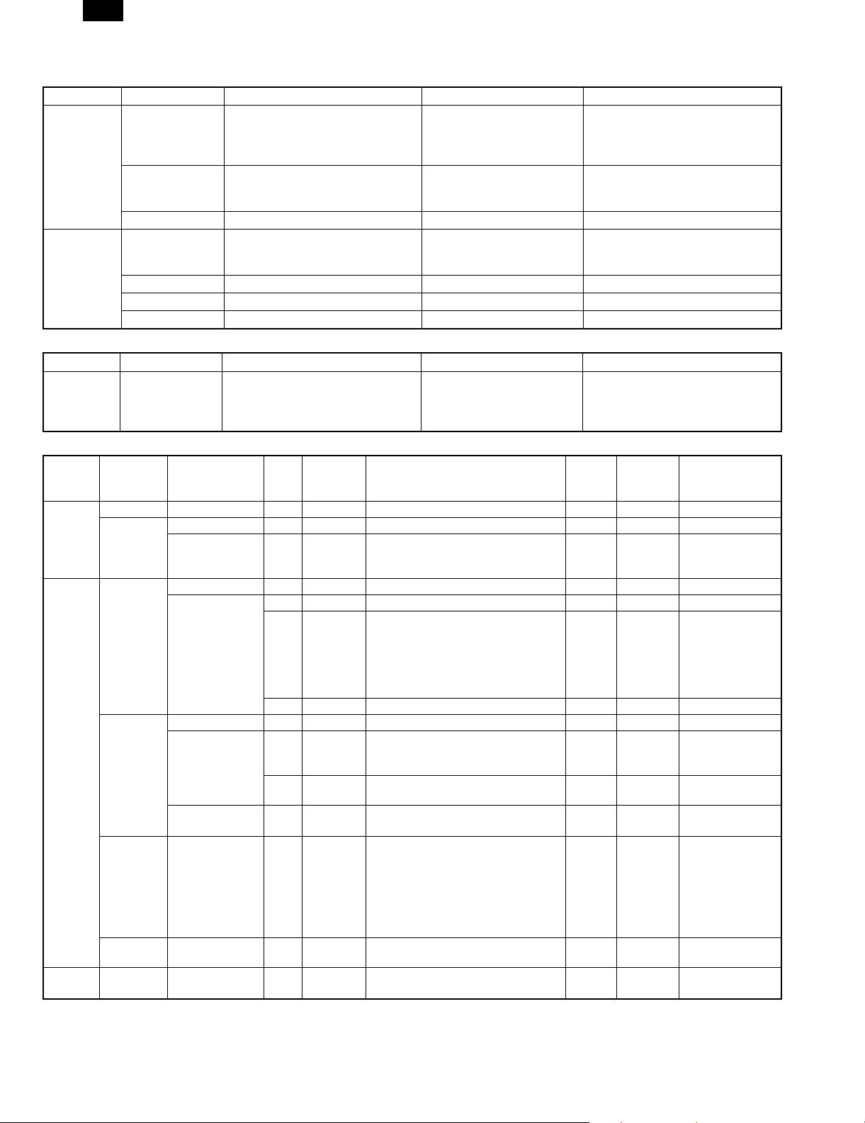
(1) List
PROGRAM NAME FUNCTION
Printer Exposure
Level
Memory Reserved
for Printer
Output Method
When Memory Is Full
Enable Bypass-Tray
Size Detection
Prohibit Notice Page
Printing
Prohibit Rotated
Output
Prohibit Bypass-Tray
Selection
Prohibit Auto Tray
Switching
Prohibit Test Page
Printing
Prohibit Changes to
Printer Settings
Prohibit Changes to
Interface Settings
Prohibit Changes to
Network Settings
Lightens or darkens printouts.
Specifies percentage of document
memory allocated to storage of printer
jobs.
Specifies whether one set or multiple sets
will be printed when the printer memory
becomes full.
Enables or disables paper size detection
for the bypass tray.
Specifies whether a notice page will be
printed when the printer memory becomes
full and divided printing is performed.
Enables/disables rotation of print image
for printing onto A4R or 8-1/2" × 11"R
paper.
Enables/disables bypass tray selection in
the ‘Auto Tray Switching’ mode.
Enables/disables automatic switching
between paper trays during printing when
paper runs out.
Enables/disables test page printing from
the printer configuration menu.
Prohibits modification of basic printer
settings in the printer configuration menu.
Prohibits modification of interface settings
in the printer configuration menu.
Prohibits modification of network settings
in the printer configuration menu.
KEY OPERATOR PROGRAMS
MEMORY RESERVED FOR PRINTER
30%
45%
35%
50%
OK
40%
55%
60%
NOTES: If ‘30%’ is specified, the maximum number of pages in a
block is 60 for A4, letter or smaller sizes. If ‘60%’ is
specified, the maximum number is 120 for A4, letter or
smaller sizes.
Since the memory in this printer is used for both copier and
printer features, the setting of this program will affect copying performance. Assign an appropriate value.
(Output Method When Memory Is Full)
When multiple sets of a document have been requested and the
document memory cannot hold the entire document, this program
gives the option to print one set or multiple sets as illustrated on page
4-4.
When the "OUTPUT METHOD WHEN MEMORY IS FULL" key is
pressed, the following display will appear.
1. Select "1 SET" or "MULTI-SET".
2. Press the "OK" key.
4 – 3
Page 24

AR-PB2
KEY OPERATOR PROGRAMS
OUTPUT METHOD WHEN MEMORY IS
FULL
OK
1 SET
MULTI-SET
NOTE: When the document memory becomes full of print job pages,
the printer will start printing the data which has been stored
in the memory. If multiple sets of the document have been
requested and "MULTI-SET" is specified with this program,
the sets will be printed as shown below. Each set of printed
sheets will be stacked offset from the previous set. Finally,
the printer will output a notice page unless it is prohibited
with a key operator program.
Notice page
Separator
sheet
1 block
Example: One set of 120-page document is printed in 60-page
blocks.
Separator
sheet
Separator
sheet
Separator
sheet
1 block
Example: Two sets of 120-page document are printed in 60-page
blocks.
(Enable Bypass-Tray Size Detection)
This program is used to enable or disable paper size detection of the
bypass tray in the printer mode. This setting does not affect the paper
size detection in the copier mode.
To enable paper size detection of the bypass tray in the printer mode,
press the "ENABLE BYPASS-TRAY SIZE DETECTION" box to display a check mark.
To disable paper size detection, press the checked box again to clear
the check mark.
NOTE: If size detection of the bypass tray is disabled, paper in the
bypass tray will always be treated as the largest allowable
size paper (either 11" × 17" or A3). If an image larger than
the paper in the bypass tray is printed, a malfunction may
occur. Be careful when disabling the size detection.
Page 61
Page 120
Page 1
Page 60
Notice page
Page 61
Page 120
Page 61
Page 120
Page 1
Page 60
Page 1
Page 60
(Prohibit Notice Page Printing)
This program is used to specify whether a notice page and separator
sheets will be printed when the printer memory becomes full and
divided printing must be performed. If notice page printing has been
enabled, a notice page will be printed at the end of a print job and
separator sheets will be printed between each block letting the user
know that the job has been divided into blocks and the user must
re-stack the document.
To prohibit notice page printing, press the "PROHIBIT NOTICE PAGE
PRINTING" box to display a check mark.
To restore notice page printing, press the checked box again to clear
the check mark.
(Prohibit Rotated Output)
If this program is not set, the print image will be rotated when the
orientation of the print image does not match that of the available
copy paper. If this program is set, a print image specified to be
printed on A4 or 8-1/2" × 11" paper will not be rotated and printed on
A4R or 8-1/2" × 11"R paper even if the specified paper is not loaded
in any tray.
To prohibit rotated output, press the "PROHIBIT ROTATED OUTPUT" box to display a check mark.
To restore rotated output, press the checked box again to clear the
check mark.
(Prohibit Bypass-Tray Selection)
If this program is set, the bypass tray will not be selected for a print
job that specifies auto paper selection or during auto tray switching.
To prohibit bypass tray selection, press the "PROHIBIT BYPASSTRAY SELECTION" box to display a check mark.
To restore bypass tray selection, press the checked box again to
clear the check mark.
(Prohibit Auto Tray Switching)
This program prevents automatic switching between paper trays in
print jobs. This program does not affect the auto tray switching function in the copier mode.
To prohibit automatic tray switching, press the "PROHIBIT AUTO
TRAY SWITCHING" box to display a check mark.
To restore automatic tray switching, press the checked box again to
clear the check mark.
(Prohibit Test Page Printing)
This program prevents printing test pages from the printer configuration menu. If this program is set, the test page print functions will not
appear in the printer configuration menu.
To prohibit test page printing, press the "PROHIBIT TEST PAGE
PRINTING" box to display a check mark.
To restore test page printing, press the checked box again to clear
the check mark.
(Prohibit Changes to Printer Settings)
This program prevents modification of basic printer settings in the
printer configuration menu. If this program is set, the printer settings
functions will not appear in the printer configuration menu.
To prohibit modification of printer settings, press the "PROHIBIT
CHANGES TO PRINTER SETTINGS" box to display a check mark.
To enable modification of printer settings, press the checked box
again to clear the check mark.
(Prohibit Changes to Interface Settings)
This program prevents modification of interface settings in the printer
configuration menu. If this program is set, the interface settings functions will not appear in the printer configuration menu.
To prohibit modification of interface settings, press the "PROHIBIT
CHANGES TO INTERFACE SETTINGS" box to display a check
mark.
To enable modification of interface settings, press the checked box
again to clear the check mark.
4 – 4
Page 25

AR-PB2
(Prohibit Changes to Network Settings)
This program prevents modification of network settings in the printer
configuration menu. If this program is set, the network settings functions will not appear in the printer configuration menu.
To prohibit modification of network settings, press the "PROHIBIT
CHANGES TO NETWORK SETTINGS" box to display a check mark.
To enable modification of network settings, press the checked box
again to clear the check mark.
(3) Notes on Printing Lengthy Documents
When printing a lengthy document, the document memory in the
printer may b ecome ful l of print data . Also, a l engthy doc ument ma y
exceed the limit of the output tray. The printer will operate as follows
depending on the conditions.
NOTE: For units with a 2GB disk drive the block size is 320 pages.
(If face down output is specified:)
a. If printing one copy of a lengthy document is specified:
Printing will stop when the number of printed sheets reaches the
limit of the output tray (if the tray can detect the limit). When the
printed paper is removed from the output tray, printing will
resume.
b. If printing multiple copies of a lengthy document is specified and
the key operator program "Output Method When Memory Is Full"
is set to "1 SET":
The printer will print only one set followed by a notice page at the
end of the job.
c. If printing multiple copies of a lengthy document is specified and
the key operator program "Output Method When Memory Is Full"
is set to "MULTI-SET":
Printed sheets will be divided into blocks* as shown in the illustration. A separator sheet will be inserted between each block. Finally, a notice page will be output. The number of pages in a block
can be changed using the key operator program "Memory
Reserved for Printer".
Notice page
Separator sheet
Separator sheet
Separator sheet
1 block
Example: Two sets of 120-page document are printed in 60-page
blocks.
(If face up output is specified:)
a. If printing one copy of a lengthy document is specified:
Printed sheets will be divided into blocks* as shown in the illustration. A separator sheet will be inserted between each block. Finally, a notice page will be output.
Separator
sheet
1 block
61
120
1
Page 120
Page 61
Page 120
Page 61
Page 60
Page 1
Page 60
Page 1
Notice page
Page 61
Page 120
Page 1
b. If printing multiple copies of a lengthy document is specified and
the key operator program "Output Method When Memory Is Full"
is set to "1 SET":
The printer will print only one set in blocks* as in 2-A and output a
notice page at the end of the job.
Notice page
Separator
sheet
1 block
Page 61
Page 120
Page 1
Page 60
c. If printing multiple copies of a lengthy document is specified and
the key operator program "Output Method When Memory Is Full"
is set to "MULTI-SET":
Printed sheets will be divided into blocks* as shown in the illustration. A separator sheet will be inserted between each block. Finally, a notice page will be output. The number of pages in a block
can be changed using the key operator program "Memory
Reserved for Printer".
Notice page
Separator
sheet
Separator
sheet
Separator
sheet
1 block
Page 61
Page 120
Page 61
Page 120
Page 1
Page 60
Page 1
Page 60
Example: Two sets of 120-page document are printed in 60-page
blocks.
* The number of pages in a block varies with the paper size, setting
of the key operator program "Memory Reserved for Printer" and
printer models.
(Notice Page Printing)
If you find that a notice page has been printed at the end of a print
job, the length of the document exceeded the printer memory
capacity as described above. The print data received from the computer has not been printed as specified. Check the print order and
arrange the order if needed. If the specified number of copies have
not been output, you have remedies: 1) Print again sending the job to
the printer multiple times. 2) Change the key operator program "Output Method When Memory Is Full" to "MULTI-SET".
(Disabling Notice Page and Separator Sheet Printing)
Notice page and separator sheet printing can be disabled using a key
operator program.
60
Page 60
4 – 5
Page 26

AR-PB2
3. Hardware setup and adjustments
A. Flash Memory write protect setting
Flash memory write protect setup (JP109)
Used to setup write protect YES/NO of flash memory.
JP109 JP109
1133
Write protect condition
(Default)
When making version up of the flash memory or when rewriting the
flash memory, short pins 2-3. In normal cases, short pins 1-2 (write
protect).
When shipping, the DIP switch is set to the following value.
JP109 1-2 Flash memory write protect
Write condition
B. Laser power setup
Enter SIM 61-4 and set the setup value to 16 (default).
If set to another value, normal print density may not be obtained.
C. Centro interface adjustment
(1) Centro interface timing adjustment
Enter SIM 67-3 and set the ACK signal width.
If communication between PC and the copier is not normally performed with the set value st to 10 (default), check the environment of
PC and change the set value.
Adjustment range: 0 ~ 255
(2) SELECT IN signal setup
Enter SIM 67-11 and set SELECT IN signal YES/NO.
The relationship between the set value (0 or 1) and SELECT IN
signal is as follows:
Set value SELECT IN signal
0 YES
1NO
If communication between PC and the copier is nor performed normally, check the environment of PC and change the set value.
D. NVRAM clear
Use SIM 67-17.
This is used to clear various setup data relating to the printer opera-
tions stored in NVRAM on the printer control PWB.
Execute this procedure to set all the setup data to default.
E. Network card check
After installing the network card, execute SIM 67-16, and the operation of the network card is displayed as NG or OK.
4 – 6
Page 27

AR-PB2
[5] Printer Driver Configuration
1. PCL5E Printer Driver
[Main] Tab
1) Setting the Number of Copies
Function name Setting the number of copies
Tab Main
Name Copies
Control Spin box
Display Function
Minimum value* 1 The number of copies will be set to
1.
Maximum value 999 The number of copies will be set to
999.
Operation The number of copies will be set.
The default value is 1.
2) Setting Duplex Print Function
Function name Setting Duplex print function
Tab Main
Name Document Style
Control List box
Display Function
Value* 1-Sided Simplex print
Value 2-Sided(Book) Duplex print of Book
binding
Value 2-Sided(Tablet) Duplex print of Tablet
binding
Value Booklet Booklet print
Operation Duplex print function will be set. At the time of
Booklet printing, the list box for setting paper
size will be displayed.
Remarks For Booklet print.
3) Setting Paper Size of Booklet Function
Function name Setting paper size of Booklet function
Tab Main
Name
Control List box
Display Function
Value* Invoice on Letter The 4-page original will
be printed on a Letter.
Value Letter on Ledger The 4-page original will
be printed on a Ledger.
Value A4 on A3 The 4-page original will
be printed on an A3.
Value A5 on A4 The 4-page original will
be printed on an A4.
Value B5 on B4 The 4-page original will
be printed on an B4.
Operation When booklet style is selected in Duplex
Print Function. This item is displayed.
The paper size of Booklet function will be set.
If this function is selected, Booklet on Letter,
etc will be displayed in the paper size column
of an application program.
4) Selecting Print Orientation
Function name Selecting print orientation
Tab Main
Name Orientation
Control Radio button
Display Function
Value* Portrait Portrait printing.
Value Landscape Landscape printing.
Operation The operation of paper at the time of printing
will be selected.
5) Setting Staple Function
Function name Setting Staple function
Tab Main
Name Stapling
Control List box
Value* None Stapling will not be executed.
Value 1Staple Stapling will be executed at 1
place.
Value 2Staple Stapling will be executed at 2
places.
Operation The number of Stapling will be set.
The stapling position will be determined by
setting the number of stapling.
This function will be displayed if Finisher that
has these functions is connected. And it
becomes possible to set this function.
5 – 1
Page 28

AR-PB2
Paper Tab
1) Setting Paper Size to be used for Print
Function name Setting paper size to be used for print.
Tab Paper
Name(note2) Paper Size
Control List box
Display 1 Display 2 Contents
Value* Letter 8 1/2 × 11 Selecting Letter
Value Legal 8 1/2 × 14 Selecting Legal
Value Ledger 11 × 17 Selecting Ledger
Value Executive 7 1/4 × 10 1/2 Selecting Executive
Value Invoice 5 1/2 × 8 1/2 Selecting Invoice
Value Foolscap 8 1/2 × 13 Selecting Foolscap
Value A4 210 × 297 mm Selecting JIS A4
Value A3 297 × 420 mm Selecting JIS A3
Value A5 148 × 210 mm Selecting JIS A5
Value A6 105 × 148 mm Selecting JIS A6
Value B4 257 × 364 mm Selecting JIS B4
Value B5 182 × 257 mm Selecting JIS B5
Value Japanese
Post Card
Value Custom
Paper Size
Value(note1) Booklet
Invoice on
Letter
Value(note1) Booklet
Letter on
Ledger
Value(note1) Booklet A4
on A3
Value(note1) Booklet A5
on A4
Value(note1) Booklet B5
on B4
100 × 148 mm Selecting Japanese
Post Card
Selecting
User-defined paper
size When Custom
Paper Size is
selected, the
display of
"millimeters" will be
default.
8 1/2 × 11 The 4-page original
will be printed on a
Letter size paper.
11 × 17 The 4-page original
will be printed on a
Ledger size paper.
297 × 420 mm The 4-page original
will be printed on an
A3 size paper.
210 × 297 mm The 4-page original
will be printed on an
A4 size paper.
257 × 364 mm The 4-page original
will be printed on an
B4 size paper.
Operation The paper size to be used for printing will be
selected by the name of paper. In the List box,
the name of paper will be displayed with the
contents of the Display 1 column. At the above of
the List box, the paper size will be displayed with
the contents of the Display 2.
If user-defined size paper is selected, the dialog
box to set the actual paper size will be displayed.
If Fit to Page function is selected, this paper size
will be the intended paper size. For the size of
each paper, print area, etc.
For printer driver, Portrait and Landscape will not
be differentiated.
Note 1 When the booklet function is selected in
"Duplex Print function, only these paper sizes are
appeared. And the value is corresponded to
designated value in "Setting Paper Size of Booklet
Function.
2) Fit to Page Function
Function name Fit to Page function
Tab Paper
Name Fit to Paper Size
Control Check box
Value* No Check Fit to Page function will not be
used.
Value Check Fit to Page function will be used.
Operation If this checkbox is checked, Fit to Page
function will be executed. Fit to Page function
is to enlarge/reduce the original to be printed
according to the paper size to be printed. The
paper size is selected in "Setting Paper Size
to be used for Print".
Note 2 if this function is selected, "Physical
Paper Size" will be displayed in this position.
3) Setting Paper Input Tray to be used for Printing
Function name Setting Paper Input Tray to be used for
printing
Tab Paper
Name Paper Source
Control List box
Display Contents
Value* Auto Select Paper Input Tray will be
automatically selected.
Value Bypass Tray Manual Feed Paper Input
Tray will be selected.
Value Bypass
Tray(manual)
Value Tray 1 Tray 1 will be selected.
Value Tray 2 Tray 2 will be selected.
Value Tray 3 Tray 3 will be selected.
Value Tray 4 Tray 4 will be selected.
Value Large
Capacity Tray
Operation Paper to be used for printing will be selected
by the name of Paper Input Tray.
In the List box, the name of Paper Input Tray
will be displayed with the contents of Display.
If the intended Paper Input Tray is not
installed, the value will not be displayed.
Manual Feed Paper Input
Tray(Wait) will be Selected.
A Large Capacity Tray will
be selected.
5 – 2
Page 29

AR-PB2
4) Starting the Selection of Different Paper
Function name Starting the selection of Different Paper
Tab Paper
Name Different Paper
Control Button
Operation If this button is pressed, Different Paper
dialog box will be displayed.
5) Starting the Selection of Transparency Inserts
Function name Starting the selection of Transparency Inserts
Tab Paper
Name Transparency Inserts
Control Button
Operation If this button is pressed, Interleave dialog box
will be displayed.
6) Selecting Paper Output Tray
Function name Selecting Paper Output Tray
Tab Paper
Name Output
Control List box
Display Contents
Value* Top Tray Output to Top Tray
Value Second Tray Output to Second Tray.
Value Offset Tray Output to Offset Tray.
Operation Paper Output Tray to be used for outputting
the print result will be selected by the name.
In the List box, the name of Paper Output
Tray will be displayed with the contents of
Display. If the intended Paper Output Tray is
not installed, the value will not be displayed.
7) Setting the way to Output Paper
Function name Setting the way to output paper
Tab Paper
Name Face Up/Down
Control List box
Display Contents
Value* Face Up Paper will be output Face Up.
Value Face Down Paper will be output Face
Down.
Operation The way to output the printed paper will be
selected.
In the List box, that will be displayed with the
contents of Display column.
If the intended way to output paper is not
supported, the value will not be displayed.
8) Setting Paper Output Order of Print Job
Function name Setting Output Order of Print Job
Tab Paper
Name Reverse Order
Control Check box
Value No check The paper output of Print Job
will be normal order.
Value* Check The paper output of Print Job
will be reverse order.
Operation The paper output order of Print Job will be
selected.
Different Paper
1) Checked/Unchecked the Setting of Different Paper
Function name Checked/Unchecked the setting of Different
Paper
Dialog Different Paper dialog box
Name Different 1st Page
Control Check box
Value* No check Setting of Different Paper is
checked.
Value Check Setting of Different Paper is
unchecked.
Operation If this checkbox is checked, the setting of
2) Setting Paper Input Tray to be Used for Printing
Different Paper
Function name Setting Paper Input Tray to be used for
Dialog Different Paper dialog box
Name Paper Source
Control List box
Value* Bypass Tray Manual Feed Paper Input
Value Bypass
Value Tray 1 Tray1 will be selected.
Value Tray 2 Tray2 will be selected.
Value Tray 3 Tray3 will be selected.
Value Tray 4 Tray4 will be selected.
Value Large Capacity
Operation The paper to be used for printing the front
3) Selecting Paper for Different Paper Print
Function name Selecting paper for Different Paper print
Dialog Different Paper dialog box
Name OK
Control Button
Operation If this button is pressed, the dialog box will be
Different Paper will be activated and the
specific Paper Input Tray can be selected
only for the 1st page of print Job.
printing Different Paper
Display Contents
Tray will be selected.
Tray(manual)
Tray
cover will be selected by the name of Paper
Input Tray.
In the List box, the name of Paper Input Tray
will be displayed with the contents of the
Display column.
If the intended Paper Input Tray is not
installed, the value will not be displayed.
closed with the setting contents enabled.
Manual Feed Paper Input
Tray (Wait) will be
selected.
Large Capacity Tray will
be selected.
5 – 3
Page 30

AR-PB2
4) Selecting Paper for Different Paper Print
Function name Selecting paper for Different Paper print
Dialog Different Paper dialog box
Name Cancel
Control Button
Operation If this button is pressed, the dialog box will be
closed with the setting contents disabled.
5) Selecting Paper for Different Paper Print
Function name Selecting paper for Different Paper print
Dialog Different Paper dialog box
Name Defaults
Control Button
Operation If this button is pressed, all the setting
contents of the dialog box will be returned to
the default value.
Transparency Inserts Dialog Box
1) Setting Paper for Interleave Print
Function Name Setting paper for interleave print
Dialog Transparency Inserts dialog box
Name Transparency Inserts
Control Check box
Value* No check No paper setting for Interleave
Print
Value Check Paper setting for Interleave Print
Operation If this checkbox is checked, the setting of
Interleave print will be activated and it
becomes possible to set paper for each page
of Print Job.
And, this is checked,
"If this "Check box" is checked, Paper Source
in the Paper tab will be forced and fixed to
"Bypass Tray (manual)".
2) Selection of Interleave page print state
Function name Selection of Interleave page state
Dialog Transparency Inserts dialog box
Name
Control Radio button
Display Function
Value* Printed Interleave page will be printed.
Value Blank Interleave print will not be printed.
Operation With this radio button, it is specified whether
to print Interleave page or to remain blank.
3) Setting Paper Input Tray to be used for Interleave Print
Function name Setting Paper Input Tray to be used for
Dialog Transparency Inserts dialog box
Name Paper Source
Control List box
Value* Tray 1 Tray 1 will be selected.
Value Tray 2 Tray 2 will be selected.
Value Tray 3 Tray 3 will be selected.
Value Tray 4 Tray 4 will be selected.
Value Large
Operation The paper to be used for Interleave Print will
Interleave Print
Display Contents
A large volume paper feed
Capacity Tray
be selected by the name of Paper Input Tray.
In list box, the name of Paper Input Tray will
be displayed with the contents of Display.
If the Paper Input Tray is not installed, the
value will not be displayed.
tray will be selected.
4) Closing Dialog Box with the setting contents enabled
Function name Closing Dialog Box with the setting contents
Dialog Transparency Inserts dialog box
Name OK
Control Button
Operation If this button is pressed, the dialog box will be
enabled
closed with the setting contents enabled.
5) Closing Dialog Box with the setting contents disabled
Function name Closing Dialog Box with the setting contents
Dialog Transparency Inserts dialog box
Name Cancel
Control Button
Operation If this button is pressed, the dialog box will be
disabled.
closed with the setting contents disabled.
6) Initialization of the contents of Dialog Box
Function name Initialization of the contents of Dialog Box
Dialog Transparency Inserts dialog box
Name Defaults
Control Button
Operation If this button is pressed, all the setting
contents of Dialog Box will be returned to the
default value.
[Advanced] Tab
5 – 4
Page 31

AR-PB2
1) Binding Edge Setting
Function name Binding Edge Setting
Tab Advanced
Name Right Edge Binding
Control Check box
Value* No check Right Edge Binding
Value Check Left Edge Binding
Operation The binding edge will be selected.
2) Starting Image Quality Dialog Box
Function name Start Image Quality Dialog Box
Tab Advanced
Name Image Quality
Control Button
Operation If this button is pressed, Image Quality Dialog
Box will be displayed.
3) Starting Font Dialog Box
Function name Starting Font Dialog Box
Tab Advanced
Name Font
Control Button
Operation If this button is pressed, Font Dialog Box will
be pressed.
[Image Quality] Dialog box
1) Setting Print Resolution
Function name Setting print resolution
Dialog Image Quality Dialog Box
Name Resolution Settings
Control List box
Display Contents
Value* 600DPI With 600DPI, printed.
Value 300DPI With 300DPI, printed.
Operation Print resolution will be set.
2) Setting whether to execute or stop Smoothing
Function name Setting whether to execute or stop Smoothing
Dialog Image Quality Dialog Box
Name Smoothing
Control List box
Display Contents
Value* On Smoothing function will be
executed.
Value Off Smoothing function will not be
executed.
Operation Whether to execute or stop Smoothing will be
selected.
Depending on a machine, this function is not
implemented. In this case, if [Smoothing]
checkbox of [Configuration] tab is OFF, this
item will not be displayed.
3) Setting the Graphics Print Method
Function name Setting the Graphics Print Method
Dialog Image Quality Dialog Box
Name Graphics Mode
Control List box
Display Contents
Value* Raster Raster Graphics will be used to
print.
Value HP-GL/2 HP-GL/2 command will be used
to print.
Operation The Graphics print method will be set.
4) Use of Toner Save function
Function name Use of Toner Save function
Dialog Image Quality Dialog Box
Name Toner Save
Control Check
Display Contents
Value* No
check
Value Check Toner Save function will not be
Operation Whether to use Toner Save function or not
will be selected.
Depending on a machine, this function is not
implemented. In this case, if [Smoothing]
checkbox of [Configuration] tab is OFF, this
item will not be displayed.
Toner Save function will not be
used.
used.
5) Closing Dialog Box with the setting contents enabled
Function name Closing Dialog Box with the setting contents
enabled
Dialog Image Quality Dialog Box
Name OK
Control Button
Operation If this button is pressed, the dialog box will be
closed with the setting contents enabled.
6) Closing Dialog Box with the setting contents disabled
Function name Closing Dialog Box with the setting contents
disabled
Dialog Image Quality Dialog Box
Name Cancel
Control Button
Operation If this button is pressed, the dialog box will be
closed with the setting contents disabled.
7) Initialization of the contents of Dialog Box
Function name Initialization of the contents of Dialog Box
Dialog Image Quality Dialog Box
Name Defaults
Control Button
Operation If this button is pressed, all the setting
contents of Dialog Box will be returned to the
default value.
5 – 5
Page 32

AR-PB2
Font Dialog Box
1) Setting the position of a font to be used
Function name Setting the position of a font to be used
Dialog Font Dialog Box
Name Font Source
Control List box
Display Contents
Value* Resident Fonts The fonts built in a printer
will be used.
Value Download Fonts All fonts will be
downloaded.
Operation The place to store a font to be used for
printing will be selected.
2) Setting the TrueType font print method
Function name Setting the TrueType font print method
Dialog Font Dialog Box
Name TrueType Mode
Control List box
Display Contents
Value* Download as
TrueType
Value Download as Bitmap Print as Bitmap
Operation TrueType font print method will be selected.
3) Closing Dialog Box with the setting contents enabled
Function name Closing Dialog Box with the setting contents
enabled
Dialog Font Dialog Box
Name OK
Control Button
Operation If this button is pressed, the dialog box will be
closed with the setting contents enabled.
4) Closing Dialog Box with the setting contents disabled
Function name Closing Dialog Box with the setting contents
disabled
Dialog Font Dialog Box
Name Cancel
Control Button
Operation If this button is pressed, the dialog box will be
closed with the setting contents disabled.
5) Initialization of the contents of Dialog Box
Function name Initialization of the contents of Dialog Box
Dialog Font Dialog Box
Name Defaults
Control Button
Operation If this button is pressed, all the setting
contents of Dialog Box will be returned to the
default value.
Download as font
Overlays Tab
1) Displaying Overlays File
Function name Displaying Overlays File
Dialog Overlays
Name Overlays
Control Frame
Operation Overlays files registered within this frame will
be displayed.
One of them is selected and displayed with
reversed.
2) Creating Overlays File
Function name Creating Overlays File
Dialog Overlays
Name Create
Control Button
Operation If this button is pressed, Select file dialog box
to create Overlays file will be displayed.
In the dialog box, the file of extension "ovp"
can be created as Overlays data file.
Then the next Print Job after closing the
dialog box will be written in the Overlays file
created.
3) Deleting Overlays file
Function name Deleting Overlays File
Dialog Overlays
Name Delete
Control Button
Operation If this button is pressed, the dialog box to
confirm if you are sure to want to delete the
Overlays file currently selected. If [OK] is
pressed, the Overlays file selected at this
point will be deleted.
4) Deleting All Overlays File
Function name Deleting All Overlays File
Dialog Overlays
Name Delete All
Control Button
Operation If this button is pressed, the dialog box to
confirm if you are sure to want to delete all
the Overlays file. If [OK] is pressed, all the
Overlays file will be deleted
5 – 6
Page 33

AR-PB2
5) Query whether to use Overlays file
Function name Query whether to use Overlays file
Dialog Overlays
Name Query Page Overlay
Control Check box
Value* No check Always Overlays will be
executed.
Value Check Whether to execute Overlays
will be queried.
Operation If this checkbox is checked, every time
printing is executed, the query is made
whether to execute Overlays.
6) Displaying the selected Overlays File
Function name Displaying Overlays file selected
Dialog Overlays
Name Selected Overlay Status
Control Frame
Operation The state of the selected Overlays file will be
displayed within this frame.
The file name including full path and macro
ID will be included there.
7) Displaying the Status of Creating Overlays File
Function name Displaying the status of creating Overlays file
Dialog Overlays
Name Overlay Creation Status
Control Frame
Operation The condition of creating Overlays file will be
displayed within this frame.
If it is in the middle of creation, that it is being
created will be displayed.
[WaterMark] tab
1) Selecting the print position of WaterMark strings
Function name Selecting the print position of WaterMark
strings
Tab WaterMark
Name Position x y
Control Slide bar
Default value(X)* 0 Printed at the center of horizontal
direction
Default value(Y)* 0 Printed at the center of vertical direction
Operation This item specifies the print position of
WaterMark strings.
The print position will be determined by using
the slide bar for horizontal direction (x) and
vertical direction (y) respectively.
For each direction, the print position will be
determined.
As to the value displayed, the center is 0 and
the left edge or upper edge is the minimum
value of –200 while right edge or lower edge
is the maximum value of 200.
Remarks The paper is surrounded by 2 slid bars when
displayed.
The paper size and the print orientation at
this point are not included in the display.
2) Returning the print position of WaterMark to center
Function name Returning the print position of WaterMark
strings to the center
Tab WaterMark
Name Center
Control Button
Operation This item set the print position of WaterMark
strings to the center.
If this button is pressed, for both directions,
the print position will return to 0.
3) Selecting t he si ze of characters of WaterMark string s
Function name Selecting the size of characters of WaterMark
Tab WaterMark
Name Size
Control Slide bar
Minimum value 6 6 point characters will be used.
Maximum value 900 900 point characters will be used.
Default value* 72 72 point characters will be used.
Operation This item specifies the size of characters of
WaterMark strings in the units of point. This
value and the font size selected in the item of
font selection will be associated.
4) Selecting the print angle of WaterMark strings
Function name Selecting the print angle of WaterMark strings
Tab WaterMark
Name Angle
Control Slide bar
Minimum value –90 Turning 90 words counterclockwise
from a horizontal position.
Maximum value +90 Turning 90 words clockwise from a
horizontal position.
Default value* 0 Printing WaterMark strings on a
horizontal position.
Operation This item selects the angle to turn WaterMark
strings.
The strings will be turned with the center a
reference point.
5 – 7
Page 34

AR-PB2
5) Selecting WaterMark strings
Function name Selecting WaterMark strings
Tab WaterMark
Name Watermark:
Control List box
Value* (none) No Watermark
Value TOP SECRET Strings TOP SECRET will
be used for Watermark.
Value CONFIDENTIAL Strings CONFIDENTIAL
will be used for
Watermark.
Value DRAFT Strings DRAFT will be
used for Watermark.
Value ORIGINAL Strings ORIGINAL will be
used for Watermark.
Value COPY Strings COPY will be
used for Watermark.
Operation This item selects the strings to be used for
WaterMark print. The above values are set at
the time of shipment. The values will be
added/deleted by pressing [Add]/[Update]
buttons. The strings to be used for
WaterMark print will be displayed in the
values.
6) Adding WaterMark strings
Function name Adding WaterMark strings
Tab Watermarks
Name Add
Control Button
Operation This item adds new WaterMark strings.
If this button is pressed, the contents of the
Watermarks tab at this pint will be added.
7) Updating WaterMark Strings
Function name Updating WaterMark strings
Tab Watermarks
Name Update
Control Button
Operation This item updates the contents of WaterMark
strings.
If this button is pressed, the contents of the
Watermarks tab at this point will be replaced
by the strings specified in " Selecting
WaterMark strings".
8) Deleting WaterMark Strings
Function name Deleting WaterMark strings
Tab Watermarks
Name Delete
Control Button
Operation This item deletes the contents of WaterMark
strings.
If this button is pressed, the contents of the
Watermarks tab at this point will be deleted.
9) Editing WaterMark Strings
Function name Editing WaterMark strings
Tab Watermarks
Name Text
Control Edit box
Operation This item edits the contents of WaterMark
strings.
With this Edit box, the strings to be used for
WaterMark print can be edited.
The shortest string is 0 character. The
longest string is 100 characters.
10) Setting Color of WaterMark Strings
Function name Setting the color of WaterMark strings
Tab Watermarks
Name Edit Color...
Control Button
Operation This item selects the color of WaterMark
strings.
If this button is pressed, the Windows
Common Dialog Box to specify colors will be
displayed and the color specified there will be
the color of WaterMark strings.
Although AR-PB2 is a monochrome printer, it
is possible to specify colors. What affects the
actual print is the specification of the
brightness of the color by the slider control at
the right end of the dialog box.
11) Setting of Font of WaterMark Strings
Function name Setting of font of WaterMark Strings
Tab Watermarks
Name Edit Fonts...
Control Button
Operation This item selects the font of WaterMark
strings.
If this button is pressed, the Windows
Common Dialog Box to specify the font will
be displayed and the font specified there will
be the font of WaterMark strings.
12) Watermark Print with Transparency and Overwriting
Function name Watermark print with transparency and
overwriting
Tab Watermarks
Name Transparent Text
Control Check box
Display Contents
Value No check Watermark print with
transparency
Value* Check Watermark print with overwriting
Operation This item specifies whether Watermark print
with transparency or with overwriting. If print
with transparency is selected, Watermark
print becomes transparent and an original
can be read.
13) Selecting Page to Execute Watermark Print
Function name Selecting the page to execute Watermark
print
Tab Watermarks
Name On First Page Only
Control Check box
Display Contents
Value* No check Watermark print will be executed
for all pages.
Value Check Watermark print will be executed
for only the 1st page.
Operation This item specifies whether to do Watermark
print for all pages or only for the 1st page of
each Print JOB.
5 – 8
Page 35

AR-PB2
[Configuration] Tab
1) Setting Option Tray Connection
Function name Setting Option Tray Connection
Tab Configuration
Name Input Tray Options
Control Radio button
Display Function
Value* (None) Option Tray is not connected.
Value 1 Tray Desk 1 Tray Desk is connected.
Value 2 Tray Desk 2 Tray Desk is connected.
Operation The Option Tray connected will be set.
2) Setting Large Capacity Tray Connection
Function name Setting Large Capacity Tray Connection
Tab Configuration
Name Large Capacity Tray
Control Check box
Display Contents
Value* No check Large Capacity Tray is not
connected.
Value Check Large Capacity Tray is
connected.
Value This item is used for setting the connection of
Large Capacity Tray.
3) Setting Duplex Unit
Function name Setting Duplex Unit
Tab Configuration
Name Duplex Unit
Control Check box
Display Contents
Value* No check Duplex unit is not built in.
Value Check Duplex unit is built in.
Operation This item is used for setting the built-in status
of Duplex Unit.
4) Setting Extended Imaging Feature
Function name Setting Extended Imaging Feature
Tab Configuration
Name Extended Imaging Feature
Control Check box
Display Contents
Value* No check Smoothing function cannot be
used.
Value Check Smoothing function can be used.
Operation This item is used for setting the status of
Smoothing function.
5) Selecting Finisher
Function name Selecting Finisher
Tab Configuration
Name Output Tray Options:
Control List box
Display Contents
Value* (none) No finisher
Value 2 Tray Finisher Connected to 2 Tray
Finisher
Value 3 Tray Finisher Connected to 3 Tray
Finisher
Operation This item is used for selecting Finisher
connected.
6) Setting Installed RAM Capacity
Function name Setting Installed RAM Capacity
Tab Configuration
Name Installed RAM:
Control List box
Display Contents
Value* 16MB RAM 16MB RAM is installed.
Value 32MB RAM 32MB RAM is installed.
Value 48MB RAM 48MB RAM is installed.
Value 64MB RAM 64MB RAM is installed.
Value 80MB RAM 80MB RAM is installed.
Operation This item is used for setting the Installed
RAM capacity.
7) Displaying About Dialog Box
Function name Displaying About dialog box
Tab Configuration
Name About
Control Button
Operation If this button is pressed, About dialog box
including the copyright of the printer driver,
etc. will be displayed. The contents are as
follows:
5 – 9
Page 36

AR-PB2
2. PostScript Printer Driver (Windows)
[Main] Tab
1) Setting the Number of Copies
Function name Setting the number of copies
Tab Main
Name Copies
Control Spin box
Display Function
Minimum value* 1 The number of copies will be set to
Maximum value 999 The number of copies will be set to
Operation The number of copies will be set.
The default value is 1.
2) Setting Duplex Print Function
Function name Setting Duplex print function
Tab Main
Name Document Style
Control List box
Value* 1-Sided Simplex print
Value 2-Sided (Book) Duplex print of Book
Value 2-Sided
(Tablet)
Value Booklet Booklet print
Operation Duplex print function will be set. At the time of
Booklet printing, the list box for setting paper
size will be displayed.
Remarks Booklet function cannot coexist with multi
page(N-Up)print.
1.
999.
Display Function
binding
Duplex print of Tablet
binding
3) Setting Paper Size of Booklet Function
Function name Setting paper size of Booklet function
Tab
Name
Control List box
Display Function
Value* Booklet on Letter The 4-page original will
be printed on Letter.
Value Booklet on Ledger The 4-page original will
be printed on Ledger.
Value Booklet on A4 The 4-page original will
be printed on A4.
Value Booklet on A3 The 4-page original will
be printed on A3.
Value Booklet on B4 The 4-page original will
be printed on B4.
Operation The paper size of Booklet function will be set.
If this function is selected, Booklet on Letter,
etc will be displayed in the paper size column
of an application program.
4) Selecting Print Orientation
Function name Selecting print orientation
Tab Main
Name Orientation
Control Radio button
Display Function
Value* Portrait Portrait printing.
Value Landscape Landscape printing.
Operation The operation of paper at the time of printing
will be selected.
5) Setting Staple Function
Function name Setting Staple function
Tab Main
Name Stapling
Control List box
Value* None Stapling will not be executed.
Value 1Staple Stapling will be executed at 1 place.
Value 2Staple Stapling will be executed at 2
places.
Operation The number of Stapling will be set.
In AR-PB2 Printing System, the stapling
position will be determined by setting the
number of stapling.
This function will be displayed if Finisher that
has these functions is connected. And it
becomes possible to set this function.
5 – 10
Page 37

AR-PB2
6) Setting Multi Page Function
Function name Setting Multi page function
Tab Main
Name N-up Printing
Control List box
Value* 1-Up Multi page function will not be used.
Value 2-Up 2 page original will be printed on 1
sheet.
Value 4-Up 4 page original will be printed on 1
sheet.
Value 6-Up 6 page original will be printed on 1
sheet.
Value 8-Up 8 page original will be printed on 1
sheet.
Value 9-Up 9 page original will be printed on 1
sheet.
Value 16-Up 16 page original will be printed on 1
sheet.
Operation Multi page function will be set. The size of an
original will be automatically reduced and
then printed.
The layout on the print of each original will be
in the order of Z characters.
7) Setting Frame Print of Multi Page Function
Function name Setting frame print of Multi Page function
Tab Main
Name Border
Control Check box
Value* No check Frame print
Value Check No frame print
Operation If the checkbox is checked, the frame print of
Multi Page Function will be performed.
Paper Tab
1) Setting Paper Size to be used for Print
Function name Setting paper size to be used for print.
Tab Paper
Name Paper Size
Control List box
Display 1 Display 2 Contents
Value* Letter 8 1/2 × 11 Selecting Letter
Value Legal 8 1/2 × 14 Selecting Legal
Value Ledger 11 × 17 Selecting Ledger
Value Executive 7 1/4 × 10 1/2 Selecting Executive
Value Invoice 5 1/2 × 8 1/2 Selecting Invoice
Value Foolscap 8 1/2 × 13 Selecting Foolscap
Value A4 210 × 297 mm Selecting JIS A4
Value A3 297 × 420 mm Selecting JIS A3
Value A5 210 × 148 mm Selecting JIS A5
Value A6 105 × 148 mm Selecting JIS A6
Value B4 257 × 364 mm Selecting JIS B4
Value B5 257 × 182 mm Selecting JIS B5
Value Japanese
Post Card
Value Custom
Paper Size
Operation The paper size to be used for printing will be
selected by the name of paper.
In the List box, the name of paper will be
displayed with the contents of the Display 1
column. At the above of the List box, the paper
size will be displayed with the contents of the
Display 2.
If user-defined size paper is selected, the dialog
box to set the actual paper size will be displayed.
If Fit to Page function is selected, this paper size
will be the intended paper size.
100 × 148 mm Selecting Japanese
Post Card
Selecting
User-defined paper
size
When Custom Paper
Size is selected, the
display of
"millimeters" will be
default.
2) Fit to Page Function
Function name Fit to Page function
Tab Paper
Name Fit to Paper Size
Control Check box
Value* No Check Fit to Page function will not be
used.
Value Check Fit to Page function will be used.
Operation If this checkbox is checked , Fit to Page function
will be executed. Fit to Page function is to
enlarge/reduce the original to be printed
according to the paper size to be printed.
If this function is selected, "Selecting the
intended size of Fit to Page" in another item will
be displayed.
5 – 11
Page 38

AR-PB2
3) Setting Paper Input Tray to be used for Printing
Function name Setting Paper Input Tray to be used for
Tab Paper
Name Paper Source
Control List box
Value* Auto Select Paper Input Tray will be
Value Bypass Tray Manual Feed Paper Input
Value Bypass Tray
Value Tray 1 Tray 1 will be selected.
Value Tray 2 Tray 2 will be selected.
Value Tray 3 Tray 3 will be selected.
Value Tray 4 Tray 4 will be selected.
Value Large
Operation Paper to be used for printing will be selected
printing
Display Contents
automatically selected.
Tray will be selected.
Manual Feed Paper Input
(manual)
Capacity Tray
by the name of Paper Input Tray.
In the List box, the name of Paper Input Tray
will be displayed with the contents of Display.
If the intended Paper Input Tray is not
installed, the value will not be displayed.
Tray(Wait) will be Selected.
A Large Capacity Tray will
be selected.
4) Starting the Selection of Different Paper
Function name Starting the selection of Different Paper
Tab Paper
Name Different Paper
Control Button
Operation If this button is pressed, Different Paper
dialog box will be displayed.
5) Starting the Selection of Interleave
Function name Starting the selection of Interleave
Tab Paper
Name Transparency Inserts
Control Button
Operation If this button is pressed, Interleave dialog box
will be displayed.
6) Selecting Paper Output Tray
Function name Selecting Paper Output Tray
Tab Paper
Name Output
Control List box
Display Contents
Value* Top Tray Output to Top Tray
Value Second Tray Output to Second Tray.
Value Offset Tray Output to Offset Tray.
Operation Paper Output Tray to be used for outputting
the print result will be selected by the name.
In the List box, the name of Paper Output
Tray will be displayed with the contents of
Display. If the intended Paper Output Tray is
not installed, the value will not be displayed.
7) Setting the way to Output Paper
Function name Setting the way to output paper
Tab Paper
Name Face Up/Down
Control List box
Display Contents
Value* Face Up Paper will be output Face Up.
Value Face Down Paper will be output Face
Down.
Operation The way to output the printed paper will be
selected.
In the List box, that will be displayed with the
contents of Display column.
If the intended way to output paper is not
supported, the value will not be displayed.
8) Setting Paper Output Order of Print Job
Function name Setting Output Order of Print Job
Tab Paper
Name Reverse Order
Control Check box
Value No check The paper output of Print Job
will be normal order.
Value* Check The paper output of Print Job
will be reverse order.
Operation The paper output order of Print Job will be
selected.
Different Paper
1) Checked/Unchecked the Setting of Different Paper
Function name Checked/Unchecked the setting of Different
Paper
Dialog Different Paper dialog box
Name Different 1st Page
Control Check box
Value* No check Setting of Different Paper is
checked.
Value Check Setting of Different Paper is
unchecked.
Operation If this checkbox is checked, the setting of
Different Paper will be activated and the
specific Paper Input Tray can be selected
only for the 1st page of print Job.
5 – 12
Page 39

AR-PB2
2) Setting Paper Input Tray to be Used for Printing
Different Paper
Function name Setting Paper Input Tray to be used for
Dialog Different Paper dialog box
Name Paper Source
Control List box
Value* Bypass Tray Manual Feed Paper Input
Value Bypass
Value Tray 1 Tray1 will be selected.
Value Tray 2 Tray2 will be selected.
Value Tray 3 Tray3 will be selected.
Value Tray 4 Tray4 will be selected.
Value Large
Operation The paper to be used for printing the front
printing Different Paper
Display Contents
Tray will be selected.
Manual Feed Paper Input
Tray(manual)
Capacity Tray
cover will be selected by the name of Paper
Input Tray.
In the List box, the name of Paper Input Tray
will be displayed with the contents of the
Display column.
If the intended Paper Input Tray is not
installed, the value will not be displayed.
Tray (Wait) will be selected.
Large Capacity Tray will be
selected.
3) Selecting Paper for Different Paper Print
Function name Selecting paper for Different Paper print
Dialog Different Paper dialog box
Name OK
Control Button
Operation If this button is pressed, the dialog box will be
closed with the setting contents enabled.
4) Selecting Paper for Different Paper Print
Function name Selecting paper for Different Paper print
Dialog Different Paper dialog box
Name Cancel
Control Button
Operation If this button is pressed, the dialog box will be
closed with the setting contents disabled.
5) Selecting Paper for Different Paper Print
Function name Selecting paper for Different Paper print
Dialog Different Paper dialog box
Name Defaults
Control Button
Operation If this button is pressed, all the setting
contents of the dialog box will be returned to
the default value.
Interleave Dialog Box
1) Setting Paper for Interleave Print
Function Name Setting paper for interleave print
Dialog Transparency Inserts dialog box
Name Transparency Inserts
Control Check box
Value* No check No paper setting for Interleave
Print
Value Check Paper setting for Interleave Print
Operation If this checkbox is checked, the setting of
Interleave print will be activated and it
becomes possible to set paper for each page
of Print Job.
"If this "Check box" is checked, Paper Source
in the Paper tab will be fixed to "Bypass
Tray(manual)".
2) Selection of Interleave page print state
Function name Selection of Interleave page state
Dialog Select Transparency Inserts dialog box
Name
Control Radio button
Display Function
Value* Printed Interleave page will be printed.
Value Blank Interleave print will not be printed.
Operation With this radio button, it is specified whether
to print Interleave page or to remain blank.
3) Setting Paper Input Tray to be used for Interleave Print
Function name Setting Paper Input Tray to be used for
Dialog Select Transparency Inserts dialog box
Name Paper Source
Control List box
Value* Tray 1 Tray 1 will be selected.
Value Tray 2 Tray 2 will be selected.
Value Tray 3 Tray 3 will be selected.
Value Tray 4 Tray 4 will be selected.
Value Large
Operation The paper to be used for Interleave Print will
Interleave Print
Display Contents
A large volume paper feed
Capacity Tray
be selected by the name of Paper Input Tray.
In list box, the name of Paper Input Tray will
be displayed with the contents of Display.
If the Paper Input Tray is not installed, the
value will not be displayed.
tray will be selected.
5 – 13
Page 40

AR-PB2
4) Closing Dialog Box with the setting contents enabled
Function name Closing Dialog Box with the setting contents
enabled
Dialog Select Transparency Inserts dialog box
Name OK
Control Button
Operation If this button is pressed, the dialog box will be
closed with the setting contents enabled.
5) Closing Dialog Box with the setting contents disabled
Function name Closing Dialog Box with the setting contents
disabled.
Dialog Select Transparency Inserts dialog box
Name Cancel
Control Button
Operation If this button is pressed, the dialog box will be
closed with the setting contents disabled.
6) Initialization of the contents of Dialog Box
Function name Initialization of the contents of Dialog Box
Dialog Select Interleave page dialog box
Name Defaults
Control Button
Operation If this button is pressed, all the setting
contents of Dialog Box will be returned to the
default value.
[Advanced] Tab
1) Binding Edge Setting
Function name Binding Edge Setting
Tab Advanced
Name Right Edge Binding
Control Check box
Value* No check Right Edge Binding
Value Check Left Edge Binding
Operation The binding edge will be selected.
2) Starting Image Quality Dialog Box
Function name Start Image Quality Dialog Box
Tab Advanced
Name Image Quality
Control Button
Operation If this button is pressed, Image Quality Dialog
Box will be displayed.
3) Starting Font Dialog Box
Function name Starting Font Dialog Box
Tab Advanced
Name Font
Control Button
Operation If this button is pressed, Font Dialog Box will
be pressed.
4) Position flipping control frame
Function name Position flipping control frame
Tab Advanced
Name Mirror Image
Control Frame
Operation Position flipping controls are put inside of this
frame
5) Vertical position flipping control
Function name Vertical position flipping control
Tab Advanced
Name Vertical
Control Check box
Value* No check Normal printing
Value Check Vertical position flipped print
Operation When this checkbox is checked, print out is in
vertical mirror imaged.
6) Horizontal position flipping control
Function name Horizontal position flipping control
Tab Advanced
Name Horizontal
Control Check box
Value* No check Normal printing
Value Check Horizontal position flipped print
Operation When this checkbox is checked, print out is in
Horizontal mirror imaged.
7) Negative Image printing control
Function name Negative Image printing control
Tab Advanced
Name Negative Image
Control Check box
Value* No check Normal printing
Value Check Negative Imaged print
Operation When this checkbox is checked, print out is in
inverted brightness im aged.
8) PS Error Infomation control
Function name PS Error Infomation control
Tab Advanced
Name PS Error Infomation
Control Check box
Value* No check No print PS Error Information
Value Check Print PS Error Information
Operation A setting is made whether to print PostScript
Error information or not when an error
occurred at a printer during printing.
5 – 14
Page 41

AR-PB2
9) PS Pass-through control
Function name PS Pass-through control
Tab Advanced
Name PS Pass-through
Control Check box
Value* No check Printer driver controlled PS
code and the setting.
Value Check Application controlled PS code
and the setting.
Operation Depending on an application, some output
PS code independently. And so PS code
cannot be controlled at the printer dirver side.
In this case, the settings at the driver side
such as N-Up, Watermark, etc. do not
function correctly. By removing this check, it
becomes possible for the printer driver to
controll PS code and the setting at the driver
side becomes enabled.
[Image Quality] Dialog box
1) Setting Print Resolution
Function name Setting print resolution
Dialog Image Quality Dialog Box
Name Resolution Settings
Control List box
Display Contents
Value* 600DPI With 600DPI, printed.
Value 300DPI With 300DPI, printed.
Operation Print resolution will be set.
2) Setting whether to execute or stop Smoothing
Function name Setting whether to execute or stop Smoothing
Dialog Image Quality Dialog Box
Name Smoothing
Control List box
Display Contents
Value* On Smoothing function will be
executed.
Value Off Smoothing function will not be
executed.
Operation Whether to execute or stop Smoothing will be
selected.
Depending on a machine, this function is not
implemented. In this case, if [Smoothing]
checkbox of [Configuration] tab is OFF, this
item will not be displayed.
3) Setting the types of HalfTone Print
Function name Setting the types of Half Tone print
Dialog Image Quality Dialog Box
Name Screen Frequency
Control Spin box
Display Function
Value* 60.0 No dithering
Minimum Value 0.1 Minimum value for the number of
lines per inch of the pattern.
Maximum Value 360.0 Maximum value for the number of
lines per inch of the pattern.
Operation Specifies values for the number of lines per
inch of the pattern.
4) Setting the types of HalfTone Print
Function name Setting the types of Half Tone print
Dialog Image Quality Dialog Box
Name Screen Angle
Control Spin box
Display Function
Value* 45.0 No dithering
Minimum Value 0.0 Minimum values for the number of
angle of the pattern.
Maximum Value 360.0 Maximum values for the number of
angle of the pattern.
Operation Specifies values for the number of angle of
the pattern.
5) Use of Toner Save function
Function name Use of Toner Save function
Dialog Image Quality Dialog Box
Name Toner Save
Control Check
Display Contents
Value* No check Toner Save function will not be
used.
Value Check Toner Save function will not be
used.
Operation Whether to use Toner Save function or not
will be selected.
Depending on a machine, this function is not
implemented. In this case, if [Smoothing]
checkbox of [Configuration] tab is OFF, this
item will not be displayed.
6) Closing DialogBox with the setting contents enabled
Function name Closing Dialog Box with the setting contents
enabled
Dialog Image Quality Dialog Box
Name OK
Control Button
Operation If this button is pressed, the dialog box will be
closed with the setting contents enabled.
5 – 15
Page 42

AR-PB2
7) Closing Dialog Box with the setting contents disabled
Function name Closing Dialog Box with the setting contents
Dialog Image Quality Dialog Box
Name Cancel
Control Button
Operation If this button is pressed, the dialog box will be
disabled
closed with the setting contents disabled.
8) Initialization of the contents of Dialog Box
Function name Initialization of the contents of Dialog Box
Dialog Image Quality Dialog Box
Name Defaults
Control Button
Operation If this button is pressed, all the setting
contents of Dialog Box will be returned to the
default value.
Font Dialog Box
1) Setting the position of a font to be used
Function name Setting the position of a font to be used
Dialog Font Dialog Box
Name Font Source
Control List box
Display Contents
Value* Resident
Fonts
Value Download
Fonts
Operation The place to store a font to be used for
printing will be selected.
2) Setting the TrueType font print method
Function name Setting the TrueType font print method
Dialog Font Dialog Box
Name Send TrueType Fonts as
Control List box
Value* Download as
Adobe(Type 1)
Value Download as
Bitmap(Type 3)
Value Download as True
Type(Type 42)
Operation TrueType font print transmission method will
be selected.
All fonts will be selected from
printer font.
All fonts will be downloaded.
Display Contents
Use outline format
Use bitmap format
Use TrueType 42
format
3) Closing Dialog Box with the setting contents enabled
Function name Closing Dialog Box with the setting contents
enabled
Dialog Font Dialog Box
Name OK
Control Button
Operation If this button is pressed, the dialog box will be
closed with the setting contents enabled.
4) Closing Dialog Box with the setting contents disabled
Function name Closing Dialog Box with the setting contents
disabled
Dialog Font Dialog Box
Name Cancel
Control Button
Operation If this button is pressed, the dialog box will be
closed with the setting contents disabled.
5) Initialization of the contents of Dialog Box
Function name Initialization of the contents of Dialog Box
Dialog Font Dialog Box
Name Defaults
Control Button
Operation If this button is pressed, all the setting
contents of Dialog Box will be returned to the
default value.
[WaterMark] tab
5 – 16
Page 43

AR-PB2
1) Selecting the print position of WaterMark strings
Function name Seelcting the print position of WaterMark
strings
Tab WaterMark
Name Position x y
Control Slide bar
Default value(X)* 0 Printed at the center of horizontal
direction
Default value(Y)* 0 Printed at the center of vertical direction
Operation This item specifies the print position of
WaterMark strings.
The print position will be determined by using
the slide bar for horizontal direction (x) and
vertical direction (y) respectively.
For each direction, the print position will be
determined.
As to the value displayed, the center is 0 and
the left edge or upper edge is the minimum
value of –200 while right edge or lower edge
is the maximum value of 200.
Remarks The paper is surrounded by 2 slid bars when
displayed. Among the contents of WaterMark
to be executed, (1) to (7) will be included
there.
The paper size and the print orientation at
this point are not included in the display.
2) Returning the print position of WaterMark to center
Function name Returning the print position of WaterMark
strings to the center
Tab WaterMark
Name Canter
Control Button
Operation This item set the print position of WaterMark
strings to the center.
If this button is pressed, for both directions,
the print position will return to 0.
3) Selecting t he size of characters of WaterMa rk st rings
Function name Selecting the size of characters of WaterMark
Tab WaterMark
Name Size
Control Slide bar
Minimum value 6 6 point characters will be used.
Maximum value 900 900 point characters will be used.
Default value* 72 72 point characters will be used.
Operation This item specifies the size of characters of
WaterMark strings in the units of point. This
value and the font size selected in the item of
font selection will be associated.
4) Selecting the print angle of WaterMark strings
Function name Selecting the print angle of WaterMark strings
Tab WaterMark
Name Angle
Control Slide bar
Minimum value –90 Turning 90 words counterclockwise
from a horizontal position.
Maximum value +90 Turning 90 words clockwise from a
horizontal position.
Default value* 0 Printing WaterMark strings on a
horizontal position.
Operation This item selects the angle to turn WaterMark
strings.
The strings will be turned with the center a
reference point.
5) Selecting WaterMark strings
Function name Selecting WaterMark strings
Tab WaterMark
Name Watermark:
Control List box
Value* (none) No Watermark
Value TOP SECRET Strings TOP SECRET
will be used for
Watermark.
Value CONFIDENTIAL Strings CONFIDENTIAL
will be used for
Watermark.
Value DRAFT Strings DRAFT will be
used for Watermark.
Value ORIGINAL Strings ORIGINAL will be
used for Watermark.
Value COPY Strings COPY will be
used for Watermark.
Operation This item selects the strings to be used for
WaterMark print. The above values are set at
the time of shipment. The values will be
added/deleted by pressing [Add]/[Update]
buttons. The strings to be used for
WaterMark print will be displayed in the
values.
6) Adding WaterMark strings
Function name Adding WaterMark strings
Tab Watermarks
Name Add
Control Button
Operation This item adds new WaterMark strings.
If this button is pressed, the contents of the
Watermarks tab at this pint will be added.
7) Updating WaterMark Strings
Function name Updating WaterMark strings
Tab Watermarks
Name Update
Control Button
Operation This item updates the contents of WaterMark
strings.
If this button is pressed, the contents of the
Watermarks tab at this point will be replaced
by the strings specified in " Selecting
WaterMark strings".
8) Deleting WaterMark Strings
Function name Deleting WaterMark strings
Tab Watermarks
Name Update
Control Button
Operation This item deletes the contents of WaterMark
strings.
If this button is pressed, the contents of the
Watermarks tab at this point will be replaced
by the strings specified in " Selecting
WaterMark strings".
5 – 17
Page 44

AR-PB2
9) Editing WaterMark Strings
Function name Editing WaterMark strings
Tab Watermarks
Name Text
Control Edit box
Operation This item edits the contents of WaterMark
strings.
With this Edit box, the strings to be used for
WaterMark print can be edited.
The shortest string is 0 character. The
longest string is 100 characters.
10) Setting Color of WaterMark Strings
Function name Setting the color of WaterMark strings
Tab Watermarks
Name Edit Color...
Control Button
Operation This item selects the color of WaterMark
strings.
If this button is pressed, the Windows
Common Dialog Box to specify colors will be
displayed and the color specified there will be
the color of WaterMark strings.
Although AR-PB2 Printing System is a
monochrome printer, it is possible to specify
colors. What affects the actual print is the
specification of the brightness of the color by
the slider control at the right end of the dialog
box.
11) Setting of Font of WaterMark Strings
Function name Setting of font of WaterMark Strings
Tab Watermarks
Name Edit Fonts...
Control Button
Operation This item selects the font of WaterMark
strings.
If this button is pressed, the Windows
Common Dialog Box to specify the font will
be displayed and the color specified there will
be the font of WaterMark strings.
13) Selecting Page to Execute Watermark Print
Function name Selecting the page to execute Watermark
print
Tab Watermarks
Name On First Page Only
Control Check box
Display Contents
Value* No check Watermark print will be
executed for all pages.
Value Check Watermark print will be
executed for only the 1st page.
Operation This item specifies whether to do Watermark
print for all pages or only for the 1st page of
each Print JOB.
14) Specifying Outline Print of Watermark Print
Function name Specifying outline print of Watermark print
Tab Watermarks
Name As Outline Only
Control Check box
Display Contents
Value* No check Normal Watermark print will be
performed.
Value Check Only the outline will be printed
in Watermark print.
Operation This item specifies whether to print only the
outline or to do normal printing for Watermark
print.
This item is enabled only when Watermark
print is print with overwriting.
[Configuration] Tab
12) Watermark Print with Transparency and Overwriting
Function name Watermark print with transparency and
overwriting
Tab Watermarks
Name Transparent Text
Contorol Check box
Display Contents
Value No check Watermark print with
transparency
Value* Check Watermark print with overwriting
Operation This item specifies whether Watermark print
with transparency or with overwriting. If print
with transparency is selected, Watermark
print becomes transparent and an original
can be read.
1) Setting Option Tray Connection
Function name Setting Option Tray Connection
Tab Configuration
Name Input Tray Options
Control Radio button
Display Function
Value* (None) Option Tray is not connected.
Value 1 Tray Desk 1 Tray Desk is connected.
Value 2 Tray Desk 2 Tray Desk is connected.
Operation The Option Tray connected will be set.
5 – 18
Page 45

AR-PB2
2) Setting Large Capacity Tray Connection
Function name Setting Large Capacity Tray Connection
Tab Configuration
Name Large Capacity Tray
Control Check box
Display Contents
Value* No check Large Capacity Tray is not
connected.
Value Check Large Capacity Tray is
connected.
Value This item is used for setting the connection of
Large Capacity Tray.
3) Setting Duplex Unit
Function name Setting Duplex Unit
Tab Configuration
Name Duplex Module
Control Check box
Display Contents
Value* No check Duplex unit is not built in.
Value Check Duplex unit is built in.
Operation This item is used for setting the built-in status
of Duplex Unit.
6) Setting Installed RAM Capacity
Function name Setting Installed RAM Capacity
Tab Configuration
Name Installed RAM:
Control List box
Display Contents
Value* 16MB RAM 16MB RAM is installed.
Value 32MB RAM 32MB RAM is installed.
Value 48MB RAM 48MB RAM is installed.
Value 64MB RAM 64MB RAM is installed.
Value 80MB RAM 80MB RAM is installed.
Operation This item is used for setting the Installed
RAM capacity.
7) Displaying About Dialog Box
Function name Displaying About dialog box
Tab Configuration
Name About
Control Button
Operation If this button is pressed, About dialog box
including the copyright of the printer driver,
etc. will be displayed. The contents are as
follows:
4) Setting Smoothing Function
Function name Setting Smoothing function
Tab Configuration
Name Smoothing
Control Check box
Display Contents
Value* No check Smoothing function cannot be
Value Check Smoothing function can be
Operation This item is used for setting the status of
Smoothing function.
used.
used.
5) Selecting Finisher
Function name Selecting Finisher
Tab Configuration
Name Output Tray Options:
Control List box
Display Contents
Value* (none) No finisher
Value 2 Tray Finisher Connected to 2 Tray
Value 3 Tray Finisher Connected to 3 Tray
Operation This item is used for selecting Finisher
connected.
Finisher
Finisher
5 – 19
Page 46

AR-PB2
3. PostScript PPD Printer Dr ive r (W indo ws)
1) Paper Size
Name Name
Letter A5
Legal A6
Ledger Hagaki
Executive B4
Invoice B5
A4 Foolscap
A3 Custom page
2) Copies
Range Display Default Function
Minimum 1 * Multi copy count is set to 1
sheet
Maximam 999 Multi copy count is set to 999
sheets
3) Orientation
Display Default Function
Portrait, * Portrait (0 degree rotation)
Landscape, Landscape (270 Degree
clockwise rotation)
Rotated Landscape Rotated Landscape (90 Degree
clockwise rotation)
4) Layout
Display Default Function
1 up, * 1 page image is printed on a
sheet
2 up 2 page image is printed on a
sheet
4 up 4 page image is printed on a
sheet
5) Paper Source
Display Default Function
Auto Select Tray * Paper source is defined
automatically.
Manual feed Manual feed is selected.
Bypass tray Bypass tray feed is selected
Tray 1 Tray 1 feed is selected
Tray 2 Tray 2 feed is selected
Tray 3 Tray 3 feed is selected
Tray 4 Tray 4 feed is selected
LCT LCT feed is selected
6) Duplex mode setting
This item describes duplex printing condition.
Dialog [More Paper Options] dialog
Display Default Function
None * Simplex printing
Flip on long edge Duplex printing with long edge
flipping.
Flip on short edge Duplex printing with short edge
flipping.
7) Output Component
Display Default Contents
2 Exit Tray * 2 Exit Tray is installed.
2 tray finisher 2 tray finisher is installed.
3 tray finisher 3 tray finisher is installed.
8) Large Capacity Tray configuration setting
Display Default Contents
Not Installed * LCT is not installed
Installed LCT is installed
9) Drawer Desk Stand configuration setting
Display Default Contents
Not Installed * No drawer desk is installed.
1 tray drawer desk
is Installed
2 tray drawer desk
is Installed
A 1 tray drawer desk is installed.
A 2 tray drawer desk is installed.
10) Duplex unit configuration setting
Display Default Contents
Not Installed * ADU is not installed.
Installed ADU is installed.
11) Installed memory setting
Display Default Contents
Standard 16MB * 16MB RAM is installed.
32MB Total RAM 32MB RAM is installed
48MB Total RAM 48MB RAM is installed
64MB Total RAM 64MB RAM is installed
80MB Total RAM 80MB RAM is installed
12) Staple selection
Display Default Contents
No stapling * No stapling is executed.
One stapling/3
Tray Finisher
Two stapling/3
Tray Finisher
One stapling/2
Tray Finisher
One stapling is executed with 3 tray
finisher
Two stapling is executed with 3 tray
finisher
One stapling is executed with 2 tray
finisher
13) Paper Delivery selection
Display Default Contents
Top Tray(Face-Up)/2 Exit Trays: * Top Tray
Face-Up
2 Exit Trays
Second Tray(Face-Up)/2 Exit Trays: Second Tray
Top Tray(Face-Up)/2Tray Finisher: Top Tray
Second Tray (Offset) (Face-Up)/
2Tray Finisher:
Top Tray(Face-Up)/3Tray Finisher: Top Tray
Second Tray(Face-Up)/3Tray Finisher: Second Tray
Offset Tray(Face-Up)/3 Tray Finisher: Offset Tray
Face-Up
2 Exit Trays
Face-Up
2Tray Finisher:
Second Tray
(Offset)
Face-Up
2Tray Finisher
Face-Up
3Tray Finisher
Face-Up
3Tray Finisher
Face-Up
3 Tray Finisher
5 – 20
Page 47

AR-PB2
Display Default Contents
Offset Tray(Face-Down)/3Tray
Finisher:
Second Tray (Offset) (Face-Down)/
2Tray Finisher:
Top Tray(Face-Down)/3Tray Finisher: Top Tray
Second Tray(Face-Down)/3Tray
Finisher:
Offset Tray
Face-Down
3Tray Finisher
Second Tray
(Offset)
Face-Down
2Tray Finisher
Face-Down
3Tray Finisher
Second Tray
Face-Down
3Tray Finisher
14) Toner save mode selection
Display Default Contents
Disable * Toner save printing is not used.
Enable Toner save printing is used.
15) Smoothing selection
Display Default Contents
Enable Edge smoothing function is used.
Disable * Edge smoothing function is not used.
16) Resolution Setting
Display Default Contents
600DPI * 600DPI printing is selected.
300DPI 300DPI printing is selected.
17) Screen angle setting
Range Display Default Function
Minimum 0 Screen angle is set to 0 degree
Maximum 360 Screen angle is set to 360
degree
Default 45 * Screen angle is set to 45
degree
21) Negative Image printing
Display Default Contents
Unchecked * Normal (Positive) image printing.
Checked Negative image printing.
22) Mirror Image printing
Display Default Contents
Unchecked * Normal image printing.
Checked horizontally mirror image printing.
23) Scaling
Range Display Default Function
Minimum 25 scaling rate is set to 25%
Maximum 400 scaling rate is set to 400%
Default 100 * scaling rate is set to 10%
24) Correct Order Printing
Display Default Contents
Disable * Correct order printing is selected.
Enable Reverse order printing is selected.
25) Smoothing Mechanism Setting
Display Default Contents
Not Installed * Smoothing function is not installed.
Installed Smoothing function is installed.
26) Staple position
Display Default Contents
Short Edge
Binding
Long Edge
Binding
* Short edge staple
Long edge staple
18) Screen frequency setting
Range Display Default Function
Minimum 0.1 Screen frequency is set to 0.1
cycle/inch.
Maximun 360 Screen frequency is set to 360
cycle/inch.
Default 60 * Screen frequency is set to 60
cycle/inch.
19) Job Timeout
Range Display Default Function
Minimum 0 * Length of Job Timeout as set
to infinity.
Maximum 999 Length of Job Timeout as set
to 999 seconds.
20) Wait Timeout
Range Display Default Function
Minimum 0 Length of wait Timeout as set
to infinity.
Maximum 999 Length of wait Timeout as set
to 999 seconds.
Default 240 * Length of wait Timeout as set
to 240 seconds.
5 – 21
Page 48

AR-PB2
[6] Configuration Report and Test Page
1. Samples
2. Description of Each contents
This section defines the meaning of each item. These items are
basically used in configuration pages, but some contents are not
used depending on language.
A. Hardware Status
Machine Information
a. Resolution
Value: 600 dpi
Example: 600 dpi
Default: 600 dpi
Description: It is always 600 dpi.
b. Language
Value: (English | Deutsch (German) | Francais (French)
|Italiano (Italian) | Nederlands (Dutch) | Espanol
(Spanish) |Svenska (Swedish)
Example: English
Default: Depends on copier language
Description: AR-PB2 includes seven language messages originally.
AR-PB2 decides the display language depending on the
language code sent from MAIN (MAIN sends the lan-
guage code based on its language ROM). This value
indicates the language that sent by MAIN to PRT.
6 – 1
Page 49

AR-PB2
Hardware Specs
a. Base Memory
Value: 16 MB
Example: 16 MB
Default: 16 MB
Description: It indicates base memory quantity of the printer board.
Basically, this is fixed at 16 MB and it cannot be
changed.
b. Optional Memory
Value: (0|16|32|48|64) MB
Example: 0MB
Default: 0MB
Description: It indicates the printer board’s optional memory quantity.
The customer (serviceman) could extend the memory
by attaching 72pin-SIMM. 0MB means optional memory
is not attached. 16MB or 32MB SIMM can be used to
this purpose.
c. Total Memory
Value: (16|32|48|64|80) MB
Example: 16MB
Default: 16MB
Description: It indicates the printer board’s total memory quantity. In
other words, it is summation of Base Memory and Option Memory.
Version Information
a. PRT
Value: #.##
Example: 2.00
Default: Depends on printer firmware version
Description: This number should be same as the PRT-PRG ROM
version number seen on serviceman simulation 22-5.
b. BOOT
Value: #.##
Example: 2.00
Default: Depends on printer firmware version
c. ICU
Value: #.##
Example: 2.00
Default: Depends on printer firmware version
Description: This number should be same as the ICU ROM version
number seen on serviceman simulation 22-5.
Installed Device
a. Duplex Module
Value: (Yes | No)
Example: Yes
Default: Depends on the Machine configuration
Description: It indicates that duplex unit is attached or not.It depends
on hardware configuration.
b. Output Device
Value: (Standard 1 Tray | Standard 2 Trays | 3 Tray Finisher|2
Tray Finisher)
Example: 3 Tray Finisher
Default: Depends on the Machine configuration
Description: It indicates attached output device.. It depends on
hardware configuration.
c. Paper Input Trays
Value: (2 trays | 3 trays | 4 trays)
Example: 2 trays
Default: Depends on the Machine configuration
Description: It indicates the number of standard input trays.It
d. Large Capacity Tray
Value: (Yes | No)
Example: Installed
Default: Depends on the Machine configuration
Description: It indicates that large capacity paper input tray(Large
e. Interface Board
Value: (None | Ethernet | TokenRing)
Example: Ethernet
Default: Depends on the Machine configuration
Description: It indicates the kind of installed network card option to
depends on hardware configuration.
Capacity Tray) is attached or not. It depends on
hardware configuration.
the slot. 10Base-T/2 and 10/100Base-T are not identified. Those two will be reported as Ethernet.
TokenRing would not be supported for AR-PB1 (ARPB2) for Japan domestic.
Available Paper Size
Appearance on
Configuration Page
Letter (81/2x11) Letter / Long Edge Feed
Letter (81/2x11R) Letter / Short Edge Feed
Legal (81/2x14) Legal / Short Edge Feed
Ledger (11x17) Ledger / Short Edge Feed
Executive (7 1/4x101/2) Executive / Short Edge Feed
Invoice (5 1/2x81/2) Invoice / Long Edge Feed
Foolscap (81/2x13) Foolscap / Short Edge Feed1
A4 A4 / Long Edge Feed
A4R A4 / Short Edge Feed
B5 B5 / Long Edge Feed
B5R B5 / Short Edge Feed
B4 B4 / Short Edge Feed
A3 A3 / Short Edge Feed
A5 A5 / Long Edge Feed
A6 A6 / Short Edge Feed
Japanese Postcard Japanese Postcard / Short Edge Feed
(Unknown) Other size (EXTRA)
(No Paper) No paper available on this tray.
(No Tray) There is a problem with this tray.
(Tray Open)
a. Tray 1 / Tray 2 / Tray 3 / Tray 4
Value: [Appropriate Paper Size]
Example: Letter (81/2x11)
Default: Depends on paper tray configuration.
Description: It indicates paper size configuration of Tray 1 /2 / 3 / 4 /
5. It depends on hardware configuration, not software
condition.
(Unknown) means paper size cannot be identified. (Tray
configuration is "EXTRA".)
This line is not printed for unavailable tray.
b. Large Capacity Tray
Value: [Appropriate Paper Size]
Example: Letter (81/2x11)
This tray is opened (except Bypass-Tray)
Description
or Tray is lifting up.
6 – 2
Page 50

AR-PB2
Default: Depends on paper tray configuration.
Description: It indicates paper size configuration of Large Capacity
Tray. It depends on hardware configuration, not
software condition. When tray is opened, nothing is
printed at here.
This line is not printed when Large Capacity Tray is not
attached.
c. Bypass-Tray
Value: [Appropriate Paper Size]
Example: Letter (81/2x11)
Default: Depends on the paper size set on Bypass Tray.
Description: It indicates paper size of set on Bypass Tray. It depends
on detection of Bypass Tray paper size. (Unknown)
means paper size cannot be detected.
B. Software Information
PostScript Emulation
a. Job Time-out
Value: # (variable length digit)
Example: 0
Default: 0
Description: This value indicates PostScript Job Time-out length
(seconds). If this time will pass from receiving the job
then PostScript interpreter will give up to print the job
and cancel.
b. Manual Feed Time-out
Value: # (variable length digit)
Example: 0
Default: 0
Description: This value indicates PostScript Manual Feed Time-out
length (seconds). If the print data break off during printing and this time will pass, then PostScript interpreter
will cancel the print job. 0 means never time out.
c. Wait Time-out
Value: # (variable length digit)
Example: 300
Default: 300
Description: This value indicates PostScript Wait Time-out length
(seconds). If the print data break off during printing and
this time will pass, then PostScript interpreter will cancel
the print job. 0 means never time out.
PCL5e Emulation
This section tells PCL5e information. This section would not appear
on AR-PB1 (Siam) for Japan domestic.
a. Font Source
Value: (Resident | Download)
Example: Resident
Default: Resident
Description: Current font source to print characters in PCL mode.
b. Font Number
Value: 0 to 45
Example: 0
Default: 0
Description: This is the current default font number used for plain
PCL job stream.
c. Font
Value: (PCL font name)
Example: Courier
Default: Courier
Description: Current default font for PCL printing.
d. Pitch Size
Value: # (variable length digit)
Example: 0.44 to 99.99 in 0.01 steps
Default: 10.00
Description: This is the current default pitch size for plain PCL job
stream.
e. Point Size
Value: # (variable length digit)
Example: 4.00 to 999.75 in 0.25 steps
Default: 12.00
Description: This is the current default point size for plain PCL job
stream.
f. Symbol Set
Value: (PCL symbol set name)
Example: Roman-8
Default: Roman-8
Description: This is the current default symbol set for plain PCL job
stream.
Network Information
a. NIC Serial Number
Value: ######
Example: 123456
Default: Depends on NIC.
Description: It indicates the NIC’s serial number. This value is written
in NIC’s ROM (or flush ROM).
b. NIC Firmware Version
Value: ######
Example: 123456
Default: Depends on NIC.
Description: It indicates the NIC’s serial number. This value is written
in NIC’s ROM (or flush ROM).
c. NetWare Print Server Name
Value: [User Definable]
Example: SHARP_990792
Default: SHARP_[NIC card serial number]
Description: This value must reflect the printer name for IPX/SPX
(NetWare).
6 – 3
Page 51

[7] FIRMWARE VERSION UP
1. Cases where flash memory rewriting is
required
In the following cases, the program in the printer control PWB flash
memory must be rewritten.
1) When a bug or other error is found
2) Data stored in the flash memory is destroyed or deleted.
3) When the flash memory is replaced.
2. Necessary tools
1) Computer (PC)
2) Parallel cable
3) Program data file (xxx.hex)
3. Procedure
1) Print the setup list to check the firmware version.
Use the operation panel of the copier to perform the following
procedure.
Offline → Environment setup → Test page print → Test page
output
2) Turn off the power and cancel write protect of the flash memory
on the printer control PWB.
Copier power OFF → Remove the printer control PWB. → Switch
the conn ectio n of jumpe r JP109 on the printer co ntrol P WB from
1-2 to 2-3. → Install the printer control PWB.
3) Connect the PC and the copier with the parallel cable.
4) Turn on the power
5) Execute SIM 67-14.
6) Download the program file.
(Note) Never turn off the power during download.
Set the PC to DOS mode → Check that the display shows
READY. → Then type > COPY xxx.hex LPT1:
and press the enter key.
( :space)
AR-PB2
The display is changed as shown below and the final display
shows OL. Then the simulation is completed.
READY → RECEIVE → ERASE → BLANK → WRITE →
VERIFY → OK
(Note) In case of an error, "NG" is displayed.
IN that case, press the interruption key to exit from SIM 67-12
menu.
If the PC still sends data, stop data sending.
Check the PC and the copier for any abnormality, and perform the above procedure again. It is requred 15 ∼ 30 min.
(Due to PC performance)
7) Print the setup list and check the firmware version.
8) Turn off the power and write-protect the flash memory on the
printer control PWB.
Copier power OFF → Remove the printer control PWB. → Switch
the conn ectio n of jumpe r JP109 on the printer co ntrol P WB from
1-2 to 2-3. → Install the printer control PWB.
9) Perform printing on the PC side and check that printing is per-
formed normally.
7 – 1
Page 52

AR-PB2
[8] FUNCTION AND OPERATION
1. Multi Function
Multiple Functions
Arbitration of contention among printing, copying and faxing is controlled by the copier. The print controller only sends the print request to the copier.
The copier judges whether the requested print job is immediately performed or not by checking the current status of the copier. The printer controller
does not control contention caused by the status of the copier.
(1) Printer/Copier
From Printer Job to Copier Job
New Job
Current Job
Receiving Print Data
(PRT)
Rasterizing Print Data
(PRT)
Transferring Print Image
(PRT-Copier)
Printing Images
(Copier)
Panel operation
(Copier)
Enables copy panel
operation without
interruption.
Continually receiving
print data.
Enables panel operation
without interruption.
Continually rasterizing
print data.
Enables copy panel
operation without
interruption while the first
page of data is being
transferred.
Allows interrupt copy
panel operation while
print data of the second
or successive pages is
being transferred.
Enables copy panel
operation without
interruption.
Continually transferring
the print image.
Copy scan (scanning an original to
be copied )
(Copier)
Enables copy scanning without
interruption.
Continually receiving print data.
Enables copy scanning without
interruption.
Continually rasterizing print data.
Enables scanning without
interruption while the first page of
data is being transferred.
Allows interrupt copying (copy
scan) while print data of the
second or successive pages is
being transferred.
In either case, clears transferred
image data and requests that the
image data be transferred again.
Enables saving of copy data into
memory without interruption while
the first page of data is being
transferred.
Allows interruption of saving of
copy data into memory while print
data of the second or successive
pages is being transferred.
In either case, clears transferred
image data and requests that the
image data be transferred again.
After the current page is printed
out, allows interruption of scanning.
Memory copy (saving
copy data into memory)
(Copier)
Enables saving of copy
data into memory without
interruption.
Continually receiving
print data.
Enables saving of copy
data into memory without
interruption.
Continually rasterizing
print data.
Enables copy printing
without interruption while
the first page of data is
being transferred.
Allows interrupt copy
printing while print data
of the second or
successive pages is
being transferred.
After the current page is
printed out, allows
interruption of saving of
copy data into memory.
Copy Printing
(Copier)
Enables copy printing
without interruption.
Continually receiving
print data.
Enables copy printing
without interruption.
Continually rasterizing
print data.
In either case, clears
transferred image data
and requests that the
image data be
transferred again.
After the current page is
printed out, allows
interruption of copy
printing.
From Copier Job to Printer Job
New Job
Current Job
Copy panel operation
(Copier)
Copy scan (scanning an
original to be copied)
(Copier)
Memory copy (saving
copy data into memory)
(Copier)
Copy Printing
(Copier)
Receiving Print Data
Continually receiving print
data until rec eiving buffer
becomes full.
Continually receiving print
data until receiving buffer
becomes full.
Continually receiving print
data until receiving buffer
becomes full.
Continually receiving print
data until receiving buffer
becomes full.
(PRT)
Rasterizing Print Data
(PRT)
Continually rasterizing print
data until image buffer
becomes full.
Continually rasterizing print
data until image buffer
becomes full.
Continually rasterizing print
data until image buffer
becomes full.
Continually rasterizing print
data until image buffer
becomes full.
8 – 1
Transferring Print Image
(PRT-Copier)
Disables print image
transfer.
Disables print image
transfer.
Disables print image
transfer.
Disables print image
transfer.
Printing Images
(Copier)
Disables print image
printing.
Disables print image
printing.
Disables print image
printing.
Disables print image
printing.
Page 53

2. Printer Operation / Message Display
AR-PB2
State Display
During initializing the printer board <Displayed on dialog window>
INITIALIZING. PLEASE WAIT.
From the end of initialization to the end of warm-up. WARMING UP. PLEASE WAIT Disabled Off Off / On
During the warm-up and waiting for starting a print job with
the data receiving /processing completed
During the idle
(Online with no data being received / printed)
During receiving the data
During processing the data
During transferring images to ERDH
During the output of print
(during printing the data stored in ERDH)
During suspending the print
(from when the print starts to be suspended by user’s
instruction during printing and to when the print job can be
actually stopped.
While the print is suspended by user.
(the data is held)
While the print data is being cleared.
(Job Cancel)
Offline
(The state in which no data is being received and printed,
and the user instruction causes Offline.)
When there is no paper in Bypass Tray during suspending
a job with Bypass Tray (manual) selected.
(The data is held.)
When there is paper in Bypass Tray during suspending a
job with Bypass Tray (manual) selected.
(The data is held.)
When there is no paper in Bypass Tray selected at the
start of printing the data, or when the print is suspended
due to paper-out.
(The data is held.)
When there is no paper in the selected tray at the start of
printing the data, or when the print is suspended due to
paper-out.
(The data is held.)
When Staple Unit is not installed properly
(the data is held)
When a stapler is empty (AR-FN1)
(The data is held.)
When a stapler is empty (AR-FN2)
(The data is held)
PLEASE WAIT. Disabled On On
READY TO PRINT.) Disabled On Off
PROCESSING PRINT DATA. Disabled On Blink
PRINTING IN PROGRESS. Disabled On Blink
<Displayed on a dialog window>
PRINTING IN PROGRESS.
PLEASE WAIT.
OFFLINE.
TO CLEAR DATA, PRESS [C].
PLEASE WAIT.
DATA IS BEING CLEARED.
OFFLINE. Disabled Off Off
ADD ******** PAPER INTO BYPASS-TRAY.
(When supplying paper as directed, the print
will start in three seconds. However, since
the size detection is not performed, the
paper sizes other than selected one will start
to be printed.)
CHANGE BYPASS-TRAY PAPER TO
********.
(When supplying paper as directed, the print
will start in three seconds. Even if the paper
in bypass tray continues to be used , the
paper needs to be reset by loading it again.
However, since the size detection is not
performed, the paper sizes other than
selected one will start to be printed.)
ADD ******** PAPER INTO BYPASS-TRAY.
(When supplying paper as directed, the print
will automatically restart in three seconds.)
OPEN * TRAY AND ADD PAPER.
(When supplying paper as directed, the print
will automatically restart after the lift-up
operation in the tray.)
CHECK STAPLER POSITION OR STAPLE
JAM.
(When checking and setting properly as
directed, the print will automatically restart.)
SLIDE THE FINISHER AWAY FROM THE
COPIER AND ADD STAPLES.
(when checking and setting properly as
directed, the print will automatically restart.)
ADD STAPLES.
(When checking and setting properly as
directed, the print will automatically restart.)
JOB
Cancel/(Clear)
Paper Selection
Disabled Off Off
Disabled Blink Blink
Enabled Off On
Enabled Off On
Enabled Off On
Enabled Off On
Enabled Off On
Enabled Off On
Enabled Off On
Enabled Off On
Enabled Off On
Online
LED
Data
LED
During suspending the print due to some errors
( Jam/Toner supply)
(The data is held)
<CONFORM TO COPIER OPERATION
SPECIFICATION.>
(Print will start just as the trouble is removed.)
8 – 2
Disabled Off On
Page 54

AR-PB2
3. Emulation Switch
Emulation setting can be switched between automatic emulation
sensing (switching) and fixed emulation modes as shown below.
AR-PB2
Automatic (PCL ↔ PS)
PCL (fixed)
/ PostScript (fixed)
Emulation switching is performed in the following manner.
PJL
Command for
Specifying an
Emulation
No
Yes
Specified
Emulation
Yes
No
Automatic
Sensing
OK
NG
Uses the emulation specified. Uses the
Uses PCL Uses a default
Emulation Setting
Automatic
Uses the
emulation
automatically
selected.
Uses PCL
Fixed
Uses a default
emulation.
emulation
specified.
emulation.
In the automatic emulation sensing mode, for print data without the
PJL command, the emulation is automatically switched either to PostScript, to PCL5e based on data sensed. In other words, automatic
emulation sensing (switching) is available only between PostScript
and PCL5e. For print data with the PJL command, the emulation is
automatically switched to the specified one with out sensing the data.
When print data without the PJL command fails to be sensed, or
when the print data is given the PJL command but the specified
emulation is not present, the data is handled in the PCL emulation.
In the fixed emulation mode, for print data without the PJL command,
the fixed emulation is used to handle the print data.Print data with the
PJL command is switched to the specified emulation. When print data
is given the PJL command but the specified emulation is not present,
the data is processed by the default emulation.
The PJL Enter command specifies PostScript and PCL5e.
4. Resolution
The printer controller supports only 600-dpi binary images in single bit
per pixel mode. The print engine does not support resolution settings
other than 600 dpi (fixed at 600 dpi). When300 dpi is specified for
resolution, 4 pixels are represented as 1 dot to create 300dpi image.
In other words, the printer controller always sends 600-dpi images to
the engine.
Main Scan
600dpi
(1 dot)
Main Scan
300dpi
(1 dot)
Reference
Position
5. Font
A. Downloadable Font Types
The Cougar printing system supports the font types for download.
Page Description
Language
AR-PB2
PCL 5e TrueType
Bitmap
Intellifont
PostScript Level 2 Type 1
Bitmap
Type 42
B. Location of Font Data
Font Data Hardware Size
PCL Roman 47
Fonts
Flash ROM #5
3MB
PS Roman 35 Fonts
D. Font Data Memory Map
Physical Address
0x0f7fffff
0x0f000000
PCL Roman/PS Roman
Flash ROM
6. Language
A. Language Selection
The printing system will automatically switch to the correct emulation
or switch to the fixed emulation mode.
Emulation setting mode AR-PB2
Automatic PS ↔ PCL
Fixed 1 PS/PCL
B. Job, control
The job control commands support PJL (Printer Job Language) which
HP printers include. PJL is available for all emulations (PCL5e,PostScript).
7. Host I/O Port Selection
There are two host I/O ports, the P1284 port and the Network(NIC)
port, as described before. The host I/O port can be selected between
the I/O port automatic port switching and the I/O fixed port setting.
The automatic port switching has two settings, between jobs and after
I/O time-out.
Sub Scan
Sub Scan
8 – 3
Page 55

AR-PB2
Setting Behavior
Automatic
Switching
Between
Jobs
When receiving data is detected through
a port, sensing data receipt from each
port, considers the port as current (port
automatic sensing processing), and
processes the data received only through
the current port. Then until the job ends
in the situation described below in 1) or
2), the data through the current port is
only processed. After the print job ends,
the port automatic sensing processing
restarts.
1) The print job is completed by the
job-end command.
2) The current port gets into the state of
waiting for data receipt, and after no
data is received for a certain time (I/O
time-out value), print job ends by the
I/O time-out.
After I/O
Time-out
When receiving data is detected through
a port, sensing data receipt from each
port, considers the port as current (port
automatic sensing processing) and
processes the data received only through
the current port. Then until the I/O
time-out in the situation described below
in 1), the data through the current port is
only processed. After the I/O time-out,
the port automatic sensing processing
restarts.
1) The current port gets into the state of
waiting for data receipt, and after no
data is received for a certain time (I/O
time-out value), the print job ends by
the I/O time-out. (When the print job
has not been completed , it ends
simultaneously.
Fixed Disables
P1284 Port
Disables
Network
Receives data only through the Network
(NIC) port.
Receives data only through the P1284
port.
(NIC) Port
Note: In the I/O time-out, the count starts at the point that data is not
acquired via the receiving buffer. When receiving the data until
the I/O time-out, the count is reset to stop.
In the between jobs setting of the automatic switching, the
conditions that a print job will be completed are as follows.
Job Start Job End
Common • PJL JOB command
PCL • PJL ENTER
LANGUAGE
command (PCL)
• PJL EOJ command
↔
• I/O Timeout
• UEL command
• <ESC>E
↔
• I/O Timeout
• Jobs starting with the
PCL data
PS • PJL ENTER
LANGUAGE
command
(POSTSCRIPT)
• UEL command
• <Ctrl-D>
• I/O Timeout
↔
• Jobs starting with the
PostScript data.
[Example of Automatic Switching]
Receiving Port Job End Data
Job1: NIC Port Yes
Job2: 1284 Port No
Job3: NIC Port Yes
1) Automatic Switching - Between Jobs
Receive Job1
NIC
1284
Receive Job2
Job1
Receive to Buffer
Receive Job3
Job2
I/O Timeout
2) Automatic - After I/O Time Out
Receive Job1
NIC
1284
Receive Job2
Job1
Receive to Buffer
Receive Job3
Job3
I/O Timeout
Job3
Job2
Job End Data
Wait
I/O Timeout
8 – 4
Page 56

AR-PB2
8. ERDH Operation
A. Hard Disk Capacity and Operation
Output behavior when Document page is longer than HD limitation.
(HD limitation for printer ; 60pages)
Face Up Face Down(Option)
N=1
61
1
120
1 set
1
60
N>1 (1) 1 set output mode (1) 1 set output mode
61
1
120
1 set
1
60
Notice Page
Notice Page
Separater
sheet and
Offset
Separater
sheet and
Offset
1 set
1 set
120
61
60
1
120
61
60
1
60
1
Notice Page
(2) N set output mode (2) N set output mode
Notice Page
61
•20
61
N set
User can select the Long Document mode by Key Operator Program.
•20
1
60
1
60
• Notice Page; ON/OFF
• Output mode; 1 set /N set
Offset...The offset function at the output device is available.
9. Printing Modes
Basic Printing Modes
The printer controller and copier / ERDH supports the following two
printing modes.
Mode-A (concurrently operates the printing operation
and storing of print data into ERDH)
This mode is intended to accelerate the first print time in the device
configuration in which Face-down delivery is supported. In the first set
of a print job, copier/ ERDH prints the first set while receiving print
data from the printer controller and storing it into itself. From the
second set on, printing is performed by reading stored data from the
ERDH. In addition, in the Face-down delivery, Mode-A is operated by
ERDH Reverse order being OFF. Typically, in this case, the Reverse
Order printing is selected in the application.
Mode-B (starts printing after copier/ ERDH has received
an entire print job)
With Face-up delivery, as the ERDH is in charge of reversing page
order, it starts printing the last page of a print job first after it has
received the entire print job from the printer controller. In addition,
when features such as Duplex or Booklet are specified, all paper
sizes conform to the operation of Mode-B. In Mode-B operation,
Notice Page
120
61
120
Separater
sheet and
Offset
determining the contents of the print job (e.g. the number of the
pages available for stapling,and multiple sizes of paper specified)
before the start of printing allows a suitable paper destination to be
selected and Finishing to be performed.
N set
61
60
1
60
1
Face-up /Face-down Selection and Mode-A /
Mode-B Control
Users are allowed to select either Face-up or Face-down.
Basically, Face-up/Face-down controls are selected for an entire print
job. However, when the multiple sizes of paper are selected, the
output into multiple destinations and Face-up /Face-down deliveries
may be performed in one job.
In both Face-up and Face-down modes, if an entire print job can be
stored in the ERDH, the document will be output in the correct page
order.
• In Reverse order feature by ERDH in the copier, users are allowed
to select either ON/OFF. (When only Face-up delivery is present,
ERDH Reverse order feature is set to OFF, which allows the
reverse order printing by the application without limiting the number of pages.)
• Users are not allowed to select either Mode-A or Mode-B. When
ERDH reverse is ON, Mode-B is automatically set,and when
ERDH reverse is OFF, Mode-A is set.
Separater
sheet and
Offset
8 – 5
Page 57

AR-PB2
Limitations in Mode-A Operation
In output devices, The output destinations available for Face-down delivery are Tray2, 3 of 3tray Finisher and Tray2 of 2tray Finisher. These support
the Mode-A operation. Limitations in the Mode-A operation are described as follows:
Output Device
STD. Face-up
Tray
3trayFIN.
Tray2/3
2tray FIN.
Tray2
ERDH
Reverse Order
ON Face-up Mode-B Mode-B for any job.
OFF Face-up Mode-A Duplex Mode-B to support the image rotation and Muti-size printing.
ON Face-up Mode-B Paper Size Mode-B. The paper output destination will be forwarded to Tray
OFF Face-up Mode-A Paper Size The paper output destination will be forwarded to Tray 1 for
OFF
(by selecting
Face-down)
ON Face-up Mode-B Paper Size Mode-B. The paper output destination will be forwarded to Tray
OFF Face-up Mode-A Paper Size The paper output destination will be forwarded to Tray 1 for
OFF
(by selecting
Face-down)
Face-up/
down
Face-down Mode-A Paper Size The paper output destination will be forwarded to Tray 1 for
Face-down Mode-A Paper Size The paper output destination will be forwarded to Tray 1 for
Basic Operation
Mode
Limitation Control
Booklet Mode-B
1for the original that includes at least one A6R, 5.5x8.5 in.,post
card, A5 or EXTRA size paper.
A6R, 5.5 x 8.5 in. post card, A5 and EXTRA sizes. If above
sized paper is included in the original, remaining output will be
forwarded to Tray 1.
Staple
(Tray3)
Duplex Mode-B to support the image rotation and Multi-size printing.
Booklet Mode-B.
Duplex Mode-B to support the image rotation and Multi-size
Booklet Mode-B because the last page data is required to be output for
Staple The selection is inhibited in the driver.
Staple Mode-B for Staple jobs.
Duplex Mode-B to support the image rotation and Multi-size printing.
Booklet Mode-B.
Duplex Mode-B to support the image rotation and Multi-size
Booklet Mode-B because the last page data is required to be output for
Staple The selection is inhibited in the driver.
Basically, this mode is used to print in the reverse order by the
application. Mode-B for Staple jobs to determine the number of
paper..
A6R,5.5x8.5 in. post card, A5 and EXTRA sizes. If above sized
paper is included in the original, remaining output will be
forwarded to Tray 1. The forwarded output will be in
incorrect(reverse) order.
printing.Face-down delivery.
the Booklet placement. Face-down delivery.
1for the original that includes paper other than A4, 8.5 x 11in.
and B5 size paper.
others than A4, Letter and B5 sizes. If above sized paper is
included in the original, remaining output will be forwarded to
Tray 1.
others than A4, Letter and B5 sizes. If above sized paper is
included in the original, remaining output will be forwarded to
Tray 1. The forwarded output will be in incorrect (reverse)order.
printing.Face-down delivery.
the Booklet placement. Face-down delivery.
• N-up is capable of the Mode-A operation.
• In the Group mode, Face-up/down, and Mode-A/Mode-B control are carried out as well as the Collate mode.
• Different First Page is capable of the Mode-A operation.
• OHP interleave paper is capable of the Mode-A operation.
The paper sizes in the table above are those at the job beginning.
When the paper unavailable for output is fed during the processing of
a job, the following operations are performed.
For example, when 2tray finisher Tray2 / Face-down is selected;
a) When the paper impossible for output, such as A3
• Mode-B and Face-up printing in N to 1 order is performed and
delivered to Tray 1.
• When the beginning is possible to output like A4 and the job
includes paper that is impossible to output such as A3:
• Mode-A and Face-down printing in 1 to N order is performed.
b) The paper of A3 size is escaped to Tray 1. This causes the
reversed (incorrect) order printing of remaining when the original
output mode was Face-down.
• Even if the A4 size paper will come after that of A3 size, the
destination is not returned to Tray 2. In other words, only one
destination change can occur in one job.
• If the output has been separated into two output trays, the
following are performed in accordance with incorrect order
printing:
• If key operator "OUTPUT METHOD WHEN MEMORY IS
FULL" is set to"1 set", cancel printing after second set.
8 – 6
Page 58

AR-PB2
• If Notice Page printing was allowed by the key operator
"PROHIBIT NOTICE PAGE PRINTING", a Notice Page is
printed. (This will be done in both case when the output after
second set is canceled or not.)
Note: Every Finisher’s paper sizes available for output are uniformed
in the Face-up and the Face-down modes.
Finisher Tray Face-up/down Paper Size
3tray Finisher Tray1 Face-up All sizes
Face-down Not used.
Tray2 Face-up B5 - 11 x 17
Face-down
Tray3 Face-up B5 - 11 x 17
Face-down
2tray Finisher Tray1 Face-up All sizes
Tray2 Face-up B5/A4/Letter
Face-down
10. Basic Face-up /down Controls and
Defaults
Exit
Device
STD Exit
tray
2bin Exit
Exit Tray
Selection
Exit Tray1ON N/A Face-up
Exit Tray1 ON N/A Face-up
ERDH
Reverse
order
Finishing
select
OFF N/A Mode-A
Tray
OFF N/A Mode-A
Exit Tray2 ON N/A Face-up
OFF N/A Mode-A
3 tray
Exit Tray1 ON N/A Face-up
Finisher
OFF N/A Mode-A
Exit Tray2 ON N/A Face-up Mode-B
OFF N/A Face-up Mode-A
OFF N/A Face-
Exit Tray3 ON Offset Face-up Mode-B
OFF Offset Face-up Mode-A
OFF Offset Face-
ON Staple Face-up Mode-B
OFF Staple Face-up Mode-B
2 tray
Exit Tray1 ON N/A Face-up
Finisher
OFF N/A Face-up Mode-A
Exit Tray2 ON Offset Face-up Mode-B
OFF Offset Face-up Mode-A
OFF Offset Face-
ON Staple Face-up Mode-B
OFF Staple Face-up Mode-B
Although Tray 1 of the 3 tray Finisher supports Face-down, it cannot
be used in the Printer mode.
Paper Destination of a Print Job with No Paper
Destination Specified
The output of print jobs with no paper destination specified is all
directed to the default exit tray. (In all exit devices, the default tray is
Top Tray, face up.)
Face-up/
down
select
only
only
only
only
down
down
only
down
Operation
Mode
Mode-B
Mode-B
Mode-B
Mode-B
Mode-A
(Mode-B)
Mode-A
(Mode-B)
Mode-B
Mode-A
(Mode-B)
11. Duplex with Multiple Paper Sources
For duplex printing, selecting a new paper size, or source empties the
duplex module and printing resumes on the next odd face. In N - 1
Print Order printing this may be accomplished by inserting a blank
page sid e into the job stream in order to f ill in the back side of a page .
This does not apply f or only an image or ientation change. This is
best illustrated by the example below.
For the job shown below, printing 8 faces on 2 sizes of paper, a face
down duplex printer will produce the mix of duplex pages shown
below
1
23
5 letter and 3 legal
sides
Should print on 5
sheets in this order
4
2
1
3
5
5
67
7
6
8
8
The system will insert blank pages if necessary to create the same
output for both 1 - N Print Order and N - 1 Print Order print jobs.
In the above-mentioned case, inserted blank pages are NOT
counted.
12. Binding Edge
The Binding Edge controls the appearance of both simplex and
duplex documents. This determines how pages will be rotated by the
system so that when bound all of the pages will have the correct
orientation in the document.
All three Binding Edge controls are supported.
Mode Control Description
Binding Edge Left Side*
(Book Style)
Text
1 (odd)
Text
1 (odd)
Right Side
(Book Style)
Text
4 (even)
In Left Side (Book Style) binding
successive faces are bound on the
edges as shown below.
Simplex
Text
2 (even)
Text
3 (odd)
Text
4 (even)
Duplex
Text
2 (even)
Text
3 (odd)
Text
4 (even)
In Right Side (Book Style) binding
successive faces are bound on the
edges a s shown below. Note the
page numbering change.
Simplex
Text
3 (odd)
Text
2 (even)
Text
1 (odd)
8 – 7
Page 59

AR-PB2
Mode Control Description
Duplex
Text
4 (even)
Top
(Tablet Style)
Text
3 (odd)
Text
2 (even)
Text
1 (odd)
In Top Side (Tablet Style) binding
successive faces are bound on the
edges as shown below.
Simplex
Text
Text
1 (odd)
1 (odd)
Text
Text
2 (even)
2 (even)
Text
Text
3 (odd)
3 (odd)
Text
Text
4 (even)
4 (even)
Duplex
Text
1 (odd)
Text
2 (even)
Text
3 (odd)
Text
4 (even)
* Default
Limitations:
1) Binding Edge can only be selected for an entire print job.
2) Access to the three Binding Edge controls will be controlled by the
print drivers. Left and Top binding will be available in Custom &
PPD driver. Right binding will only be available in Custom driver.
(Interaction of Page Orientation and Binding Edge
for Duplex Printing)
There are a total of 6 combinations of Binding Edge and Page Orientation settings, however, both Right and Left Edge Binding require the
same final page orientations and hence are combined. The 4 resultant, unique duplex document appearances are shown below.
Settings of Page
Orientation and
Binding Edge
1 Page Orientation:
Portrait
Binding Edge:
Left or Right (Book)
2 Page Orientation:
Portrait
Binding Edge:
Top (Tablet)
Appearance of
Document
Texttext
Tex
Text
HP 5 Si
Nomenclature
Portrait
Book
Portrait
Tablet
13. Memory Configuration
The following ROM are supported.
EPROM: Boot & Simulation Program
Flash ROM: Program &Font data
Boot ROM is selectable between EPROM and Flash ROM #5 using
the jumper switching.
Flash ROM #5
4MB
Main Program
Flash ROM #5 3MB PCL Roman 47 Fonts
PS Roman 35 Fonts
Flash ROM #5 1MB Boot/Simulation Program
ROM Memory Map
Physical Address
0x1fff ffff
0x1fd0 0000
0x1fc0 0000
0x0f80 0000
0x0f10 0000
0x0100 0000
Boot & Diag Program
PCL/PS Roman Fonts
Main Program
Power On Reset
Exception Vector
Flash ROM #5
8MB
14. Printer control PWB switch (short pin)
and LED display
Switch, LED Function
Switch RESET switch
(SW102)
ABORT switch
(SW101)
LED POWER-LED
(D114)
RUN-LED
(D113)
Software
status
STO-LED
(D109)
ST1-LED
(D110)
ST2-LED
(D111)
ST3-LED
(D112)
Processor and peripheral device
initialization
MMI* generation to processor
PWB power ON. Lighted when
supplying power.
Processor operating status.
Lights up when operating.
Lights UPD71055-A port 0 bit 4 at
"0."
Lights UPD71055-A port 0 bit 5 at
"0."
Lights UPD71055-A port 0 bit 6 at
"0."
Lights UPD71055-A port 0 bit 7 at
"0."
3 Page Orientation:
Landscape
Binding Edge:
Top (Tablet)
4 Page Orientation:
Landscape
Binding Edge:
Left or Right (Book)
Text
Text
Landscape
Book
Texttext
Landscape
Tablet
8 – 8
Page 60

AR-PB2
(Error message)
F9 0 Content ICU-PRT communication trouble
Detail
Cause SCSI LSI abnormality
ICU PWB defect
SCSI connector connection defect
Printer PWB defect
Check and remedy Replace the printer PWB.
Check the SCSI connector.
Replace the printer PWB.
Replace the ICU PWB.
F9 01 Content PRT DRAM trouble
Detail DRAM trouble in the option printer board. (Check when turning on the power)
Cause DRAM module is broken and access cannot be made.
DRAm module installation trouble
Check and remedy Check with SIM 57-1.
F9 02 Content PRT Centro port check error
Detail Option printer board Centro port trouble
Cause Centro port defect
Printer PWB defect
Check and remedy Replace the printer board.
F9 03 Content Network card trouble.
Detail Network card self test trouble.
Cause Network card defecft.
Printer PWB defect.
Network card connector connection defect.
Check and remedy Check the Network card connector.
Replace the printer PWB.
Replace the Network card.
F9 04 Content Printer program error.
Detail Program data trouble in the option printer board.
Cause Flash memory data is destroied.
Check and remedy Replace or rewrite the Flash memory.
F9 05 Content Short of memory capacity on the ICU PWB
Detail Total memory is less than 16MB on the ICU PWB.
Cause Memory defect
Check and remedy Replace the ICU PWB
F9 10 Content PRT SCSI LSI abnormality
Detail An error occurred in SCSI communication with the option printer board.
Cause SCSI LSI abnormality
Check and remedy Replace the printer PWB.
F9 90 Content ICU-PRT communication trouble (PRT detection)
Detail
Cause SCSI LSI abnormality
Check and remedy Replace the printer PWB.
Replace the printer PWB.
SIMM memory connector connection defect
ICU PWB defect
Wrong type SIMM memory is installed
Replace the memory
Check the memory connector
ICU PWB defect
Printer PWB defect
SCSI connector connection defect
Check the SCSI connector.
Replace the printer PWB.
Replace the ICU PWB.
ICU PWB defect
SCSI connector connection defect
Printer PWB defect
Check the SCSI connector.
Replace the printer PWB.
Replace the ICU PWB.
Page 61

AR-PB2
q
COPYRIGHT © 1998 BY SHARP CORPORATION
All rights reserved.
Printed in Japan.
No part of this publication may be reproduced,
stored in a retrieval system, or transmitted,
in any form or by any means,
electronic, mechanical, photocopying, recording, or otherwise,
without prior written permission of the publisher.
SHARP CORPORATION
Printing & Reprographic Systems Group
Quality & Reliability Control Center
Yamatokoriyama, Nara 639-1186, Japan
1998 December Printed in Japan N
 Loading...