

Page 1
AR-PB2
[3] SETUP
1. Parts list
Before installing the printer kit, check that all the following items are prepared.
Be careful that the necessary parts depend on the environment of the copier (model and unit installation).
Part name Model Q’ty Note
Accessories SCSI cable 1
Wire saddle 1
Band 1
Printer box installing screw 5
Printer control PWB 1 With frame
Printer driver Windows 95 PCL5E Driver (FD) 1
Windows NT PCL5E Driver (FD) 1
Windows 95 PS Driver (FD) 1
Windows NT PS Driver (FD) 1
Installation manual 1
Operation Manual 1
Label 1 Only for Sweden and Norway
Option Expansion board AR-EB1 1 The expansion board is necessary to install
SIMM memory 16MB ED0 type/Without parity/70ns or above
32MB
Network card AR-NC1D 1 10BASE T/10BASE 2
Separate purchase
(User purchase)
Printer (parallel) cable Necessary when the copier is used as a
the printer kit to the AR-S280.
The copier ICU PWB requires the total
memory of 16MB(20MB) or more.
The printer control PWB has two expansion
slots to which 16MB or 32MB memory can
be additionally installed. (16MB onboard)
stand-alone machine.
2. Preliminary work
If the version of the three kinds of flash memory installed to the copier
is older than the following, upgrade is required.
Check version number, and perform the upgrade if necessary. (For
the procedure, refer to the Technical Report.)
Flash memory version
Operation PWB 2.xx
ICU PWB 2.xx
PCU PWB 2.xx
3. Hardware setup
A. Common work
(1) Printer unit installation
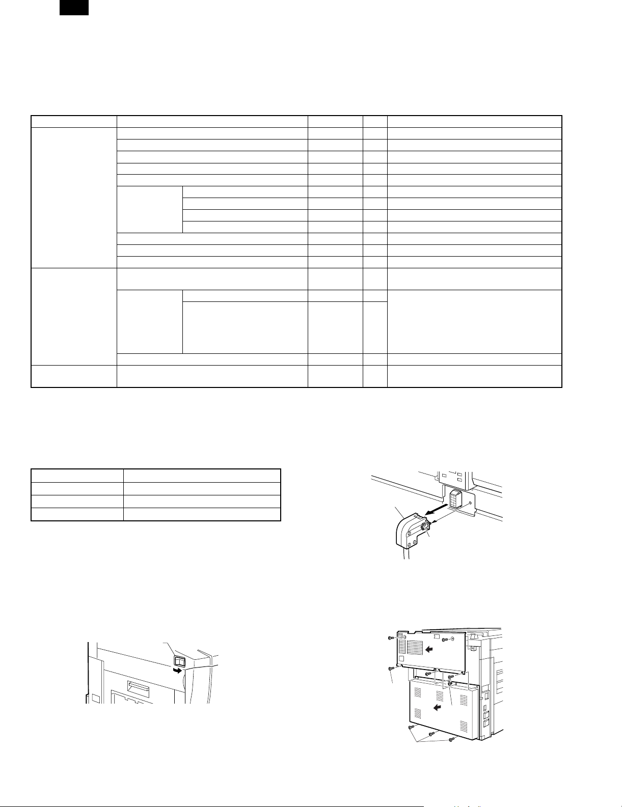
1) Turn "OFF" the main switch located on the left-hand side on the
main copier unit.
Next, unplug the power plug of the main copier unit from the
outlet.
Main switch
"OFF"
2) Removing the rear cover of the main copier unit.
If equipped with the RADF/ADF/SPF, loosen the securing screws
which the hold the RADF/ADF/SPF connector and remove the
connector from the main copier unit.
Connector
Screw
Remove the five securing screws which hold the rear cover of
main copier unit, and remove the rear cover.
Next, loosen the upper central one of four securing screws which
hold the rear lower cover, then remove the rest three screws.
Remove the rear lower cover.
Rear cover
Securing
screw
Loosen
Rear lower cover
3 – 1
Securing screws
Page 2
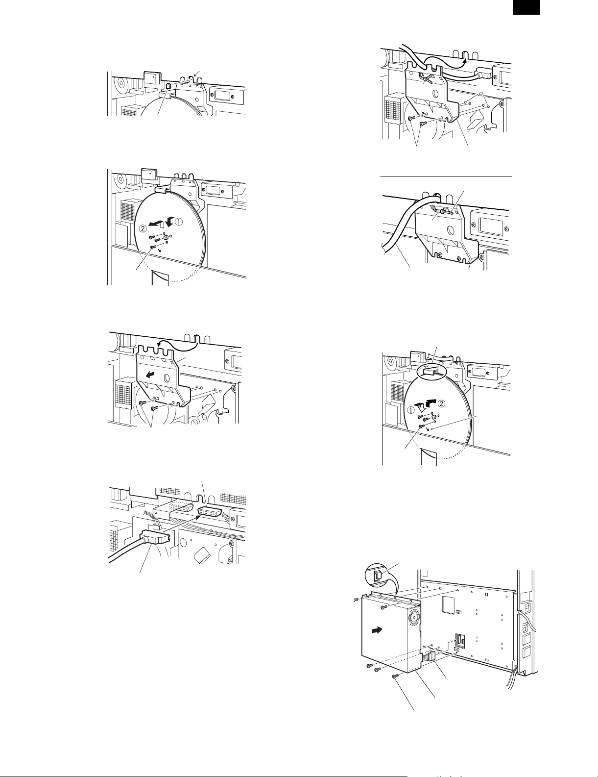
3) Cut out the central one of three notches of upper rear cover with a
nipper.
Notches
AR-PB2
A notch
4) Remove the three securing screws which hold the flywheel and
remove the flywheel.
Flywheel
Securing
screw
5) Remove the two securing screws which hold the shield line guide
to the main drive frame and remove the shield line guide.
Shield line
guide
Binding
band
Securing screws
Binding
band
Printer relay cable
Cut away the surplus
Ribs
Shield line guide
8) Reinstall the flywheel (which was removed in the step 4) onto the
main drive shaft while slipping inside the exterior. Use the three
securing screws to secure it.
Make sure the arrow mark on flywheel faces toward you.
Caution
Securing screws
6) Plug the printer relay cable connector into the most right hand port
on the ICU board.
Port on the ICU board
Printer relay cable
7) Place the printer relay cable into the central notch of shield line
guide (the location with a letter P) and attach it temporarily with a
binding band as shown in the illustration.
Next, insert the two ribs on the main drive frame through the
positioning holes of shield line guide, then use the two securing
screws to secure it.
Place the printer relay cable as shown in the illustration, then
tighten the binding band and cut away the excess.
Flywheel
Engraved
arrow mark
Securing
screw
<Caution> Do not turn the flywheel with hands after installation
since it may cause damage to the gears.
9) Connect the power connector of printer box unit to the power
supply port on the main copier unit, then attach the printer box unit
on the holes of F/P box mounting plate using the hooks.
Using the 5 print er bo x securi ng screw s, at tach the p rinter box to
the mounting plate.
Hook
Power connector
3 – 2
Printer box unit
Printer box securing screw
Page 3

AR-PB2
10) Remove the securing screws holding the P side OP cover in the
rear lower cover which was removed in the step 2, then remove
the P side OP cover.
Next, paste an attached label at the position only for Sweden
and Norway as shown in the illustration.
P side OP cover
Label
Securing
screws
11) Hook the rear lower cover on the securing screw 4 which was
loosened in the step 1 as shown in the illustration.
Next, tighten the securing screws 1, 2 and 3 temporarily,
which were removed in the step 2 and tighten the securing
screw 4 which was loosened, tighten the securing screws 5,
6 and 7.
Reinstall the rear cover tighten (which was removed in the step
2) to the original position by putting it onto the securing screws
1, 2 and 3 which temporarily secure the rear cover, then
tighten the securing screws 1, 1 and 3 after tightening the
securing screws 8 and 9.
Securing screw
Rear cover
Wire saddle
Printer relay cable
(2) Expansion memory installation
a. Memory expansion in the printer control PWB
Normally there is no need for memory expansion. However,
memory expansion will increase the printer performance.
When printing graphics or complex data, memory expansion will
increase printing speed.
Memory of 16MB or 32MB can be installed to the two slots. (16MB
onboard)
Different capacity of memory can be installed to the two slots.
The total memory after expansion may be 32, 48, 64, or 80MB.
After the above procedure, select VM Option menu and set the
total memory capacity.
b. ICU PWB memory expansion
The copier ICU PWB requires total memory capacity of 16 (20)MB
or more.
Memory of 16MB or 32MB can be installed to the two slots. (4MB
onboard)
Different capacity of memory can be installed to the two slots.
Loosened
screw
Rear lower
cover
Securing
screws
12) If equipped with the RADF/ADF/SPF, reinstall the connector that
was removed in the step 2 to the original position on the main
copier unit, then secure with screws attached to the connector.
Screw
Connector
1 Connect the printer relay cable to the connector of printer
box.
2 Attach the packaged wire saddle to the printer relay cable.
3 Insert and attach the wire saddle at the position of rear lower
cover as shown in the illustration.
B. Stand-alone environment (Printer (parallel)
cable connection)
Plug the connector of the Centronics cable (sold separately) into the
Centronics port on the printer box base.Plug the other connector into
the laser printer port on a personal computer.
Connector going to the
laser printer port on the
personal computer
Centronics cable
(sold separately)
3 – 3
Page 4

AR-PB2
C. Network environment (Network card installation)
1) Insert the network card into the network card slot on the printer
control PWB. and fix it with screws.
4. Setup on the copier side
A. Setup by simulation
Setup the following items. For parallel I/F, setup, if there is no trouble
in operations, there is no need to change any settings.
Content Simulation No. Set value
System configuration setup 26-44 1
Print counter count mode setup 26-05
Parallel I/F timing adjustment 67-03
Parallel I/F select IN signal timing 67-11
B. Setup by key operator program
Refer to the section of the key operator program and make setting
according to the user environment.
5. Software installation and setup
Checking the Hardware and Software Requirements
You will need the following hardware and software in order to install
the printer driver.
Computer
Type
Operating
System
CPU Windows 3.1/Windows 95: 486SX or better
RAM Windows 3.1/
IBM PC/AT or compatible computer equipped with
a bi-directional parallel interface
Windows 3.1x, Windows 95, Windows 98,
Windows NT 4.
Windows 98: 486DX/ 66 MHz or better Pentium or
better is recommended.)
Windows NT4.0: 486/ 25MHz or better
8 MB or more (12 MB or more
Windows 95:
Windows 98:
Windows NT 4.0:
is recommended.)
16 MB or more (32 MB or more
is recommended.)
16 MB or more
2) Install the printer control PWB to the copier.
3) Connect the network cable to the network card connector.
A. Printer driver installation
Installing Printer Drivers
A compatible printer driver must be loaded to enable a computer’s
operating system to communicate with the printer.
The following procedures describe how to install each of the supplied
printer drivers. To install multiple Windows printer drivers, the installation procedure must be performed for each driver.
NOTE: Before installing a printer driver, be sure to read the
"Readme" file for the latest information.
Windows 95 with Plug & Play (parallel connections only)
When using Windows 95 with plug & play*, follow the procedure
below.
* The plug & play feature is effective if both the computer and
peripheral equipment are equipped with IEEE 1284 compliant
parallel interface.
1. Ensure that the printer cable is connected between your computer
and the printer and then turn on the printer.
2. Start Windows on your computer.
NOTE: Before installing the printer driver, be sure to close all other
open applications.
If you use Windows 95 on a personal computer with the plug &
play feature, the ‘Update Device Driver Wizard’ window will appear. If the ‘New Hardware Found’ window appears, follow the
procedure below:
1 Click the ‘Driver from Disk Provided by Hardware
Manufacturer’ button and then click ‘OK’.
2 When the ‘Install From Disk’ window appears, insert the
desired diskette into the floppy disk drive. Type A:\ (if the
floppy disk drive is designated as drive A) and click the ‘OK’
button.
3 Proceed to step 4.
3 – 4
Page 5

AR-PB2
• If either the ‘Update Device Driver Wizard’ window or the ‘New
Hardware Found’ window does not appear, follow the procedure of Windows 95/Windows 98 without Plug & Play.
3. Insert the desired diskette into the floppy disk drive and click the
‘Next’ button.
4. Highlight the desired printer driver and click ‘Next’ to continue.
5. Ensure that ‘Yes’ is checked to use the printer as the default
printer. Click the ‘Next’ button.
6. Follow the instructions on your screen to install the supplied
printer driver.
NOTE: In step 4 above, selecting ‘SHARP AR-PB2 PS’ (the Post-
Script® driver) will generally provide the highest-quality output and support the widest range of printer features. Alternatively, select either the SHARP AR-PB2 PS PPD (Sharpspecific PostScript® PPD) or the SHARP AR-PB2 PCL5e
driver.
Windows 98 with Plug & Play (parallel connections only)
When using Windows 98 with plug & play*, follow the procedure
below.
* The plug & play feature is effective if both the computer and
peripheral equipment are equipped with IEEE 1284 compliant
parallel interface.
1. Ensure that the printer cable is connected between your computer
and the printer and then turn on the printer.
2. Start Windows on your computer.
NOTE: Before installing the printer driver, be sure to close all other
open applications.
• If you use Windows 98 on a personal computer with plug &
play feature, the ‘Add New Hardware Wizard’ window will appear. If the ‘Add New Hardware Wizard’ window does not appear, follow the procedure of Windows 95/Windows 98 without
Plug & Play.
3. Click the ‘Next’ button.
4. Ensure that ‘Search for the best driver for your device’ is selected
and click the ‘Next’ button.
5. Insert the desired diskette into the floppy disk drive and click the
‘Next’ button.
6. Highlight the desired printer driver and click ‘Next’ to continue.
7. Ensure that ‘Yes’ is checked to use the printer as the default
printer. Click the ‘Next’ button.
8. Follow the instructions on your screen to install the supplied
printer driver
NOTE: In step 6 above, selecting ‘SHARP AR-PB2 PS’ (the Post-
Script® driver) will generally provide the highest-quality output and support the widest range of printer features. Alternatively, select either the SHARP AR-PB2 PS PPD (Sharpspecific PostScript® PPD) or the SHARP AR-PB2 PCL5e
driver.
Windows 95/Windows 98 without Plug & Play
1. Ensure that the printer cable is connected between your computer
and the printer and then turn on your computer.
2. On the Windows 95/Windows 98 Start menu, highlight ‘Settings’,
then highlight and click on ‘Printers’.
3. From the Printers window, select ‘Add Printer’ to run the Add
Printer Wizard. Then click ‘Next’.
4. If Windows 95/Windows 98 has been configured for network
operation, it might be necessary to select ‘Local Printer’ or ‘Network Printer’. Select the appropriate option, and click ‘Next’ to
continue.
5. If ‘Network Printer’ was selected, specify the appropriate Network
Path or Queue Name and click ‘Next’.
6. The installation window will display a list of printer models and
manufacturers. Click the ‘Have Disk’ button.
7. Insert the desired diskette into the floppy disk drive. Select the
floppy disk drive and click the ‘OK’ button. Highlight the desired
printer driver, and click ‘Next’ to continue.
8. If ‘Local Printer’ was selected in step 4 above, the installation
window will display a list of possible port assignments. Select the
correct port, usually LPT1 for local printers and click ‘Next’.
9. Ensure that ‘Yes’ is checked to use the printer as the default
printer. Click the ‘Next’ button.
• At this time, ensure that the printer has been turned on and has
been connected to your computer.
10. Follow the instructions on your screen to install the supplied
printer driver.
NOTE: In step 7 above, selecting ‘SHARP AR-PB2 PS’ (the Post-
Script® driver) will generally provide the highest-quality output and support the widest range of printer features. Alternatively, select either the SHARP AR-PB2 PS PPD (Sharpspecific PostScript® PPD) or the SHARP AR-PB2 PCL5e
driver.
Windows 3.1x
1. Ensure that the printer cable is connected between your computer
and the printer and then turn on your computer.
2. From the Program Manager, double click on ‘Control Panel’ located in the ‘Main’ menu.
3. From the Control Panel, double click on ‘Printers.’
4. Click on ‘Add’ and then ‘Install Unlisted or Updated Printer.’
5. Click on ‘Install.’
6. Insert the desired diskette into the drive, select the floppy disk
drive an d click the ‘OK’ butto n. Then select th e desired printer
driver.
7. Follow the instructions on your screen to install the supplied
printer driver.
NOTE: In step 6 above, selecting ‘SHARP AR-PB2 PS’ (the Post-
Script® driver) will generally provide the highest-quality output and support the widest range of printer features. Alternatively, select the SHARP AR-PB2 PCL5e driver. The SHARP
AR-PB2 PS PPD (SHARP-specific PostScript® PPD) cannot
be installed on Windows 3.1x.
Windows NT 4.0
1. Ensure that the printer cable is connected between your computer
and the printer and then turn on your computer.
2. On the Start menu, highlight ‘Settings’, then highlight and click on
‘Printers’.
3. From the Printers window, select Add Printer to run the Add
Printer Wizard.
4. Select ‘My computer’ or ‘Network Printer Server’ and then click on
‘Next’.
5. Follow the instructions on your screen to install the supplied
printer driver.
NOTE: In step 5 above, selecting ‘SHARP AR-PB2 PS’ (the Post-
Script® driver) will generally provide the highest-quality output and support the widest range of printer features. Alternatively, select either the SHARP AR-PB2 PS PPD (Sharpspecific PostScript® PPD) or the SHARP AR-PB2 PCL5e
driver.
6. Setup under network environment
Check the user environment and make setup according to the Operation Manual attached to the network card.
3 – 5
 Loading...