

Page 1
AR-PB2
[8] FUNCTION AND OPERATION
1. Multi Function
Multiple Functions
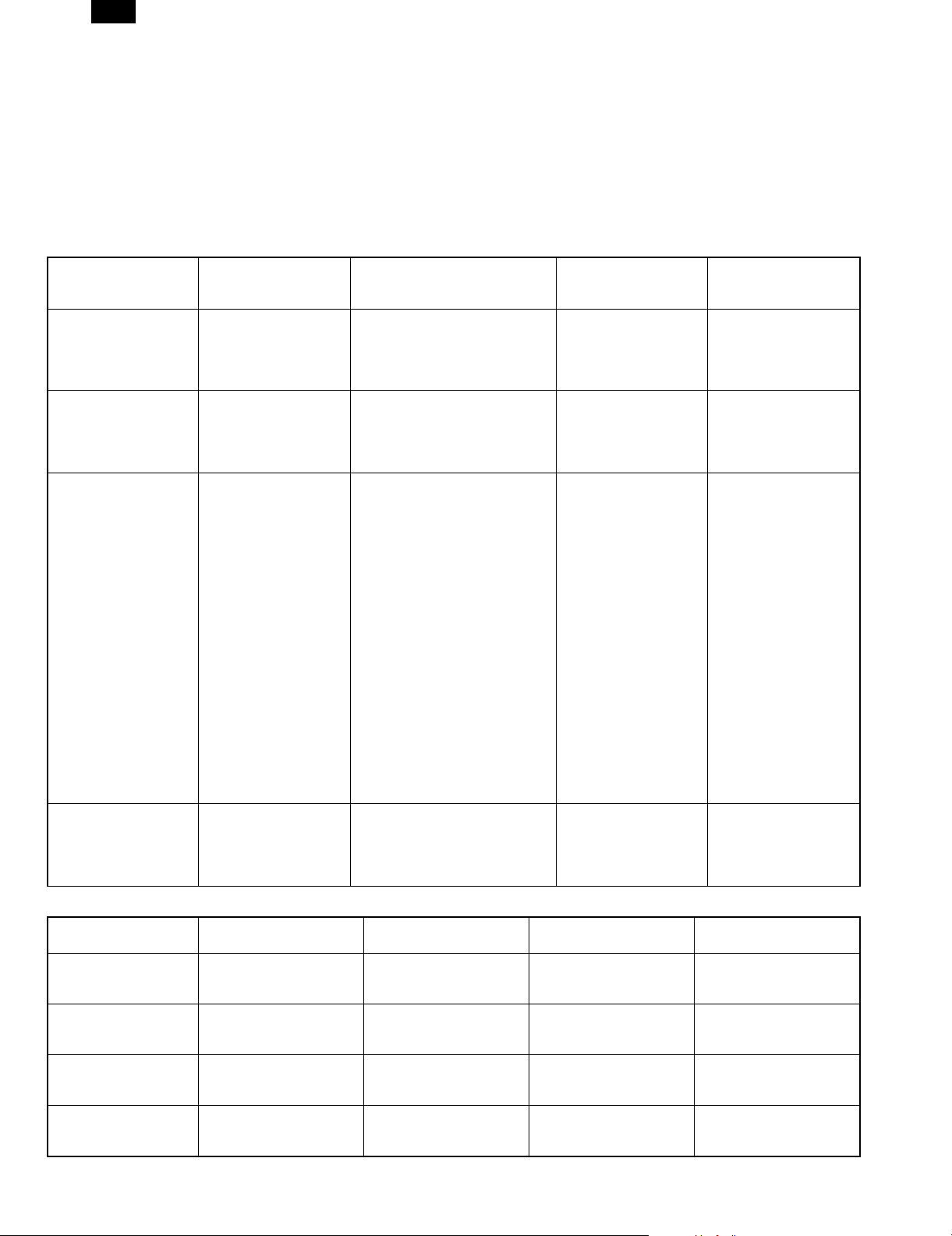
Arbitration of contention among printing, copying and faxing is controlled by the copier. The print controller only sends the print request to the copier.
The copier judges whether the requested print job is immediately performed or not by checking the current status of the copier. The printer controller
does not control contention caused by the status of the copier.
(1) Printer/Copier
From Printer Job to Copier Job
New Job
Current Job
Receiving Print Data
(PRT)
Rasterizing Print Data
(PRT)
Transferring Print Image
(PRT-Copier)
Printing Images
(Copier)
Panel operation
(Copier)
Enables copy panel
operation without
interruption.
Continually receiving
print data.
Enables panel operation
without interruption.
Continually rasterizing
print data.
Enables copy panel
operation without
interruption while the first
page of data is being
transferred.
Allows interrupt copy
panel operation while
print data of the second
or successive pages is
being transferred.
Enables copy panel
operation without
interruption.
Continually transferring
the print image.
Copy scan (scanning an original to
be copied )
(Copier)
Enables copy scanning without
interruption.
Continually receiving print data.
Enables copy scanning without
interruption.
Continually rasterizing print data.
Enables scanning without
interruption while the first page of
data is being transferred.
Allows interrupt copying (copy
scan) while print data of the
second or successive pages is
being transferred.
In either case, clears transferred
image data and requests that the
image data be transferred again.
Enables saving of copy data into
memory without interruption while
the first page of data is being
transferred.
Allows interruption of saving of
copy data into memory while print
data of the second or successive
pages is being transferred.
In either case, clears transferred
image data and requests that the
image data be transferred again.
After the current page is printed
out, allows interruption of scanning.
Memory copy (saving
copy data into memory)
(Copier)
Enables saving of copy
data into memory without
interruption.
Continually receiving
print data.
Enables saving of copy
data into memory without
interruption.
Continually rasterizing
print data.
Enables copy printing
without interruption while
the first page of data is
being transferred.
Allows interrupt copy
printing while print data
of the second or
successive pages is
being transferred.
After the current page is
printed out, allows
interruption of saving of
copy data into memory.
Copy Printing
(Copier)
Enables copy printing
without interruption.
Continually receiving
print data.
Enables copy printing
without interruption.
Continually rasterizing
print data.
In either case, clears
transferred image data
and requests that the
image data be
transferred again.
After the current page is
printed out, allows
interruption of copy
printing.
From Copier Job to Printer Job
New Job
Current Job
Copy panel operation
(Copier)
Copy scan (scanning an
original to be copied)
(Copier)
Memory copy (saving
copy data into memory)
(Copier)
Copy Printing
(Copier)
Receiving Print Data
Continually receiving print
data until receiving bu ffer
becomes full.
Continually receiving print
data until receiving buffer
becomes full.
Continually receiving print
data until receiving buffer
becomes full.
Continually receiving print
data until receiving buffer
becomes full.
(PRT)
Rasterizing Print Data
(PRT)
Continually rasterizing print
data until image buffer
becomes full.
Continually rasterizing print
data until image buffer
becomes full.
Continually rasterizing print
data until image buffer
becomes full.
Continually rasterizing print
data until image buffer
becomes full.
8 – 1
Transferring Print Image
(PRT-Copier)
Disables print image
transfer.
Disables print image
transfer.
Disables print image
transfer.
Disables print image
transfer.
Printing Images
(Copier)
Disables print image
printing.
Disables print image
printing.
Disables print image
printing.
Disables print image
printing.
Page 2
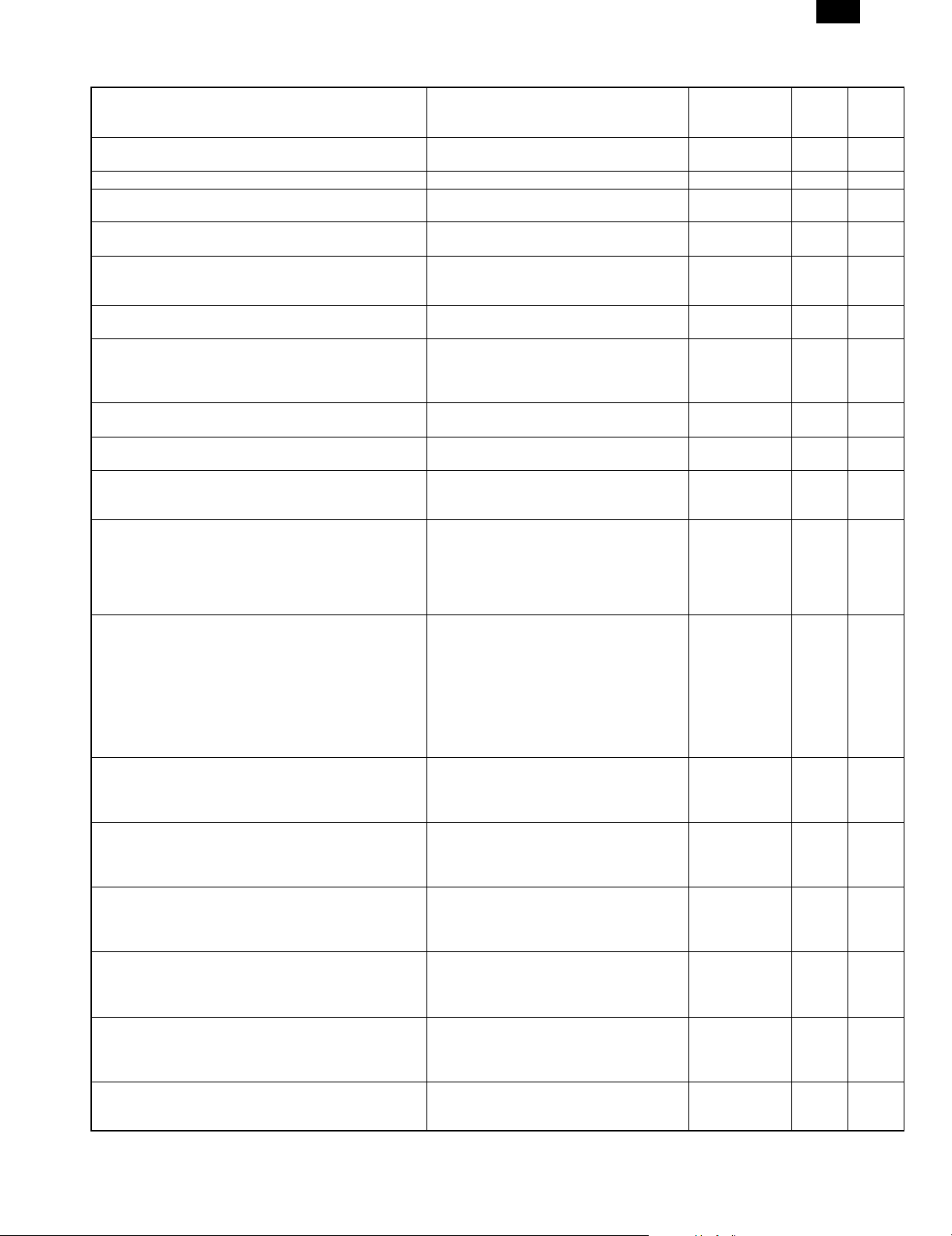
2. Printer Operation / Message Display
AR-PB2
State Display
During initializing the printer board <Displayed on dialog window>
INITIALIZING. PLEASE WAIT.
From the end of initialization to the end of warm-up. WARMING UP. PLEASE WAIT Disabled Off Off / On
During the warm-up and waiting for starting a print job with
the data receiving /processing completed
During the idle
(Online with no data being received / printed)
During receiving the data
During processing the data
During transferring images to ERDH
During the output of print
(during printing the data stored in ERDH)
During suspending the print
(from when the print starts to be suspended by user’s
instruction during printing and to when the print job can be
actually stopped.
While the print is suspended by user.
(the data is held)
While the print data is being cleared.
(Job Cancel)
Offline
(The state in which no data is being received and printed,
and the user instruction causes Offline.)
When there is no paper in Bypass Tray during suspending
a job with Bypass Tray (manual) selected.
(The data is held.)
When there is paper in Bypass Tray during suspending a
job with Bypass Tray (manual) selected.
(The data is held.)
When there is no paper in Bypass Tray selected at the
start of printing the data, or when the print is suspended
due to paper-out.
(The data is held.)
When there is no paper in the selected tray at the start of
printing the data, or when the print is suspended due to
paper-out.
(The data is held.)
When Staple Unit is not installed properly
(the data is held)
When a stapler is empty (AR-FN1)
(The data is held.)
When a stapler is empty (AR-FN2)
(The data is held)
PLEASE WAIT. Disabled On On
READY TO PRINT.) Disabled On Off
PROCESSING PRINT DATA. Disabled On Blink
PRINTING IN PROGRESS. Disabled On Blink
<Displayed on a dialog window>
PRINTING IN PROGRESS.
PLEASE WAIT.
OFFLINE.
TO CLEAR DATA, PRESS [C].
PLEASE WAIT.
DATA IS BEING CLEARED.
OFFLINE. Disabled Off Off
ADD ******** PAPER INTO BYPASS-TRAY.
(When supplying paper as directed, the print
will start in three seconds. However, since
the size detection is not performed, the
paper sizes other than selected one will start
to be printed.)
CHANGE BYPASS-TRAY PAPER TO
********.
(When supplying paper as directed, the print
will start in three seconds. Even if the paper
in bypass tray continues to be used , the
paper needs to be reset by loading it again.
However, since the size detection is not
performed, the paper sizes other than
selected one will start to be printed.)
ADD ******** PAPER INTO BYPASS-TRAY.
(When supplying paper as directed, the print
will automatically restart in three seconds.)
OPEN * TRAY AND ADD PAPER.
(When supplying paper as directed, the print
will automatically restart after the lift-up
operation in the tray.)
CHECK STAPLER POSITION OR STAPLE
JAM.
(When checking and setting properly as
directed, the print will automatically restart.)
SLIDE THE FINISHER AWAY FROM THE
COPIER AND ADD STAPLES.
(when checking and setting properly as
directed, the print will automatically restart.)
ADD STAPLES.
(When checking and setting properly as
directed, the print will automatically restart.)
JOB
Cancel/(Clear)
Paper Selection
Disabled Off Off
Disabled Blink Blink
Enabled Off On
Enabled Off On
Enabled Off On
Enabled Off On
Enabled Off On
Enabled Off On
Enabled Off On
Enabled Off On
Enabled Off On
Online
LED
Data
LED
During suspending the print due to some errors
( Jam/Toner supply)
(The data is held)
<CONFORM TO COPIER OPERATION
SPECIFICATION.>
(Print will start just as the trouble is removed.)
8 – 2
Disabled Off On
Page 3
AR-PB2
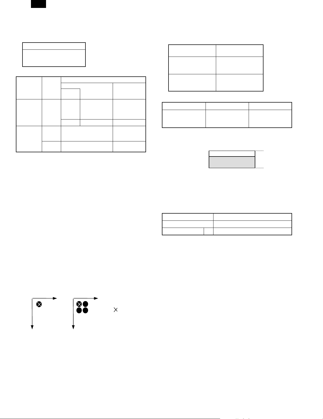
3. Emulation Switch
Emulation setting can be switched between automatic emulation
sensing (switching) and fixed emulation modes as shown below.
AR-PB2
Automatic (PCL ↔ PS)
PCL (fixed)
/ PostScript (fixed)
Emulation switching is performed in the following manner.
PJL
Command for
Specifying an
Emulation
No
Yes
Specified
Emulation
Yes
No
Automatic
Sensing
OK
NG
Uses the emulation specified. Uses the
Uses PCL Uses a default
Emulation Setting
Automatic
Uses the
emulation
automatically
selected.
Uses PCL
Fixed
Uses a default
emulation.
emulation
specified.
emulation.
In the automatic emulation sensing mode, for print data without the
PJL command, the emulation is automatically switched either to PostScript, to PCL5e based on data sensed. In other words, automatic
emulation sensing (switching) is available only between PostScript
and PCL5e. For print data with the PJL command, the emulation is
automatically switched to the specified one with out sensing the data.
When print data without the PJL command fails to be sensed, or
when the print data is given the PJL command but the specified
emulation is not present, the data is handled in the PCL emulation.
In the fixed emulation mode, for print data without the PJL command,
the fixed emulation is used to handle the print data.Print data with the
PJL command is switched to the specified emulation. When print data
is given the PJL command but the specified emulation is not present,
the data is processed by the default emulation.
The PJL Enter command specifies PostScript and PCL5e.
4. Resolution
The printer controller supports only 600-dpi binary images in single bit
per pixel mode. The print engine does not support resolution settings
other than 600 dpi (fixed at 600 dpi). When300 dpi is specified for
resolution, 4 pixels are represented as 1 dot to create 300dpi image.
In other words, the printer controller always sends 600-dpi images to
the engine.
Main Scan
600dpi
(1 dot)
Main Scan
300dpi
(1 dot)
Reference
Position
5. Font
A. Downloadable Font Types
The Cougar printing system supports the font types for download.
Page Description
Language
AR-PB2
PCL 5e TrueType
Bitmap
Intellifont
PostScript Level 2 Type 1
Bitmap
Type 42
B. Location of Font Data
Font Data Hardware Size
PCL Roman 47
Fonts
Flash ROM #5
3MB
PS Roman 35 Fonts
D. Font Data Memory Map
Physical Address
0x0f7fffff
0x0f000000
PCL Roman/PS Roman
Flash ROM
6. Language
A. Language Selection
The printing system will automatically switch to the correct emulation
or switch to the fixed emulation mode.
Emulation setting mode AR-PB2
Automatic PS ↔ PCL
Fixed 1 PS/PCL
B. Job, control
The job control commands support PJL (Printer Job Language) which
HP printers include. PJL is available for all emulations (PCL5e,PostScript).
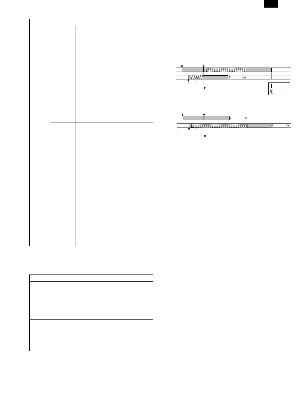
7. Host I/O Port Selection
There are two host I/O ports, the P1284 port and the Network(NIC)
port, as described before. The host I/O port can be selected between
the I/O port automatic port switching and the I/O fixed port setting.
The automatic port switching has two settings, between jobs and after
I/O time-out.
Sub Scan
Sub Scan
8 – 3
Page 4
AR-PB2
Setting Behavior
Automatic
Switching
Between
Jobs
When receiving data is detected through
a port, sensing data receipt from each
port, considers the port as current (port
automatic sensing processing), and
processes the data received only through
the current port. Then until the job ends
in the situation described below in 1) or
2), the data through the current port is
only processed. After the print job ends,
the port automatic sensing processing
restarts.
1) The print job is completed by the
job-end command.
2) The current port gets into the state of
waiting for data receipt, and after no
data is received for a certain time (I/O
time-out value), print job ends by the
I/O time-out.
After I/O
Time-out
When receiving data is detected through
a port, sensing data receipt from each
port, considers the port as current (port
automatic sensing processing) and
processes the data received only through
the current port. Then until the I/O
time-out in the situation described below
in 1), the data through the current port is
only processed. After the I/O time-out,
the port automatic sensing processing
restarts.
1) The current port gets into the state of
waiting for data receipt, and after no
data is received for a certain time (I/O
time-out value), the print job ends by
the I/O time-out. (When the print job
has not been completed , it ends
simultaneously.
Fixed Disables
P1284 Port
Disables
Network
Receives data only through the Network
(NIC) port.
Receives data only through the P1284
port.
(NIC) Port
Note: In the I/O time-out, the count starts at the point that data is not
acquired via the receiving buffer. When receiving the data until
the I/O time-out, the count is reset to stop.
In the between jobs setting of the automatic switching, the
conditions that a print job will be completed are as follows.
Job Start Job End
Common • PJL JOB command
PCL • PJL ENTER
LANGUAGE
command (PCL)
• PJL EOJ command
↔
• I/O Timeout
• UEL command
• <ESC>E
↔
• I/O Timeout
• Jobs starting with the
PCL data
PS • PJL ENTER
LANGUAGE
command
(POSTSCRIPT)
• UEL command
• <Ctrl-D>
• I/O Timeout
↔
• Jobs starting with the
PostScript data.
[Example of Automatic Switching]
Receiving Port Job End Data
Job1: NIC Port Yes
Job2: 1284 Port No
Job3: NIC Port Yes
1) Automatic Switching - Between Jobs
Receive Job1
NIC
1284
Receive Job2
Job1
Receive to Buffer
Receive Job3
Job2
I/O Timeout
2) Automatic - After I/O Time Out
Receive Job1
NIC
1284
Receive Job2
Job1
Receive to Buffer
Receive Job3
Job3
I/O Timeout
Job3
Job2
Job End Data
Wait
I/O Timeout
8 – 4
Page 5

AR-PB2
8. ERDH Operation
A. Hard Disk Capacity and Operation
Output behavior when Document page is longer than HD limitation.
(HD limitation for printer ; 60pages)
Face Up Face Down(Option)
N=1
61
1
120
1 set
1
60
N>1 (1) 1 set output mode (1) 1 set output mode
61
1
120
1 set
1
60
Notice Page
Notice Page
Separater
sheet and
Offset
Separater
sheet and
Offset
1 set
1 set
120
61
60
1
120
61
60
1
60
1
Notice Page
(2) N set output mode (2) N set output mode
Notice Page
61
•20
61
N set
User can select the Long Document mode by Key Operator Program.
•20
1
60
1
60
• Notice Page; ON/OFF
• Output mode; 1 set /N set
Offset...The offset function at the output device is available.
9. Printing Modes
Basic Printing Modes
The printer controller and copier / ERDH supports the following two
printing modes.
Mode-A (concurrently operates the printing operation
and storing of print data into ERDH)
This mode is intended to accelerate the first print time in the device
configuration in which Face-down delivery is supported. In the first set
of a print job, copier/ ERDH prints the first set while receiving print
data from the printer controller and storing it into itself. From the
second set on, printing is performed by reading stored data from the
ERDH. In addition, in the Face-down delivery, Mode-A is operated by
ERDH Reverse order being OFF. Typically, in this case, the Reverse
Order printing is selected in the application.
Mode-B (starts printing after copier/ ERDH has received
an entire print job)
With Face-up delivery, as the ERDH is in charge of reversing page
order, it starts printing the last page of a print job first after it has
received the entire print job from the printer controller. In addition,
when features such as Duplex or Booklet are specified, all paper
sizes conform to the operation of Mode-B. In Mode-B operation,
Notice Page
120
61
120
Separater
sheet and
Offset
determining the contents of the print job (e.g. the number of the
pages available for stapling,and multiple sizes of paper specified)
before the start of printing allows a suitable paper destination to be
selected and Finishing to be performed.
N set
61
60
1
60
1
Face-up /Face-down Selection and Mode-A /
Mode-B Control
Users are allowed to select either Face-up or Face-down.
Basically, Face-up/Face-down controls are selected for an entire print
job. However, when the multiple sizes of paper are selected, the
output into multiple destinations and Face-up /Face-down deliveries
may be performed in one job.
In both Face-up and Face-down modes, if an entire print job can be
stored in the ERDH, the document will be output in the correct page
order.
• In Reverse order feature by ERDH in the copier, users are allowed
to select either ON/OFF. (When only Face-up delivery is present,
ERDH Reverse order feature is set to OFF, which allows the
reverse order printing by the application without limiting the number of pages.)
• Users are not allowed to select either Mode-A or Mode-B. When
ERDH reverse is ON, Mode-B is automatically set,and when
ERDH reverse is OFF, Mode-A is set.
Separater
sheet and
Offset
8 – 5
Page 6

AR-PB2
Limitations in Mode-A Operation
In output devices, The output destinations available for Face-down delivery are Tray2, 3 of 3tray Finisher and Tray2 of 2tray Finisher. These support
the Mode-A operation. Limitations in the Mode-A operation are described as follows:
Output Device
STD. Face-up
Tray
3trayFIN.
Tray2/3
2tray FIN.
Tray2
ERDH
Reverse Order
ON Face-up Mode-B Mode-B for any job.
OFF Face-up Mode-A Duplex Mode-B to support the image rotation and Muti-size printing.
ON Face-up Mode-B Paper Size Mode-B. The paper output destination will be forwarded to Tray
OFF Face-up Mode-A Paper Size The paper output destination will be forwarded to Tray 1 for
OFF
(by selecting
Face-down)
ON Face-up Mode-B Paper Size Mode-B. The paper output destination will be forwarded to Tray
OFF Face-up Mode-A Paper Size The paper output destination will be forwarded to Tray 1 for
OFF
(by selecting
Face-down)
Face-up/
down
Face-down Mode-A Paper Size The paper output destination will be forwarded to Tray 1 for
Face-down Mode-A Paper Size The paper output destination will be forwarded to Tray 1 for
Basic Operation
Mode
Limitation Control
Booklet Mode-B
1for the original that includes at least one A6R, 5.5x8.5 in.,post
card, A5 or EXTRA size paper.
A6R, 5.5 x 8.5 in. post card, A5 and EXTRA sizes. If above
sized paper is included in the original, remaining output will be
forwarded to Tray 1.
Staple
(Tray3)
Duplex Mode-B to support the image rotation and Multi-size printing.
Booklet Mode-B.
Duplex Mode-B to support the image rotation and Multi-size
Booklet Mode-B because the last page data is required to be output for
Staple The selection is inhibited in the driver.
Staple Mode-B for Staple jobs.
Duplex Mode-B to support the image rotation and Multi-size printing.
Booklet Mode-B.
Duplex Mode-B to support the image rotation and Multi-size
Booklet Mode-B because the last page data is required to be output for
Staple The selection is inhibited in the driver.
Basically, this mode is used to print in the reverse order by the
application. Mode-B for Staple jobs to determine the number of
paper..
A6R,5.5x8.5 in. post card, A5 and EXTRA sizes. If above sized
paper is included in the original, remaining output will be
forwarded to Tray 1. The forwarded output will be in
incorrect(reverse) order.
printing.Face-down delivery.
the Booklet placement. Face-down delivery.
1for the original that includes paper other than A4, 8.5 x 11in.
and B5 size paper.
others than A4, Letter and B5 sizes. If above sized paper is
included in the original, remaining output will be forwarded to
Tray 1.
others than A4, Letter and B5 sizes. If above sized paper is
included in the original, remaining output will be forwarded to
Tray 1. The forwarded output will be in incorrect (reverse)order.
printing.Face-down delivery.
the Booklet placement. Face-down delivery.
• N-up is capable of the Mode-A operation.
• In the Group mode, Face-up/down, and Mode-A/Mode-B control are carried out as well as the Collate mode.
• Different First Page is capable of the Mode-A operation.
• OHP interleave paper is capable of the Mode-A operation.
The paper sizes in the table above are those at the job beginning.
When the paper unavailable for output is fed during the processing of
a job, the following operations are performed.
For example, when 2tray finisher Tray2 / Face-down is selected;
a) When the paper impossible for output, such as A3
• Mode-B and Face-up printing in N to 1 order is performed and
delivered to Tray 1.
• When the beginning is possible to output like A4 and the job
includes paper that is impossible to output such as A3:
• Mode-A and Face-down printing in 1 to N order is performed.
b) The paper of A3 size is escaped to Tray 1. This causes the
reversed (incorrect) order printing of remaining when the original
output mode was Face-down.
• Even if the A4 size paper will come after that of A3 size, the
destination is not returned to Tray 2. In other words, only one
destination change can occur in one job.
• If the output has been separated into two output trays, the
following are performed in accordance with incorrect order
printing:
• If key operator "OUTPUT METHOD WHEN MEMORY IS
FULL" is set to"1 set", cancel printing after second set.
8 – 6
Page 7

AR-PB2
• If Notice Page printing was allowed by the key operator
"PROHIBIT NOTICE PAGE PRINTING", a Notice Page is
printed. (This will be done in both case when the output after
second set is canceled or not.)
Note: Every Finisher’s paper sizes available for output are uniformed
in the Face-up and the Face-down modes.
Finisher Tray Face-up/down Paper Size
3tray Finisher Tray1 Face-up All sizes
Face-down Not used.
Tray2 Face-up B5 - 11 x 17
Face-down
Tray3 Face-up B5 - 11 x 17
Face-down
2tray Finisher Tray1 Face-up All sizes
Tray2 Face-up B5/A4/Letter
Face-down
10. Basic Face-up /down Controls and
Defaults
Exit
Device
STD Exit
tray
2bin Exit
Exit Tray
Selection
Exit Tray1ON N/A Face-up
Exit Tray1 ON N/A Face-up
ERDH
Reverse
order
Finishing
select
OFF N/A Mode-A
Tray
OFF N/A Mode-A
Exit Tray2 ON N/A Face-up
OFF N/A Mode-A
3 tray
Exit Tray1 ON N/A Face-up
Finisher
OFF N/A Mode-A
Exit Tray2 ON N/A Face-up Mode-B
OFF N/A Face-up Mode-A
OFF N/A Face-
Exit Tray3 ON Offset Face-up Mode-B
OFF Offset Face-up Mode-A
OFF Offset Face-
ON Staple Face-up Mode-B
OFF Staple Face-up Mode-B
2 tray
Exit Tray1 ON N/A Face-up
Finisher
OFF N/A Face-up Mode-A
Exit Tray2 ON Offset Face-up Mode-B
OFF Offset Face-up Mode-A
OFF Offset Face-
ON Staple Face-up Mode-B
OFF Staple Face-up Mode-B
Although Tray 1 of the 3 tray Finisher supports Face-down, it cannot
be used in the Printer mode.
Paper Destination of a Print Job with No Paper
Destination Specified
The output of print jobs with no paper destination specified is all
directed to the default exit tray. (In all exit devices, the default tray is
Top Tray, face up.)
Face-up/
down
select
only
only
only
only
down
down
only
down
Operation
Mode
Mode-B
Mode-B
Mode-B
Mode-B
Mode-A
(Mode-B)
Mode-A
(Mode-B)
Mode-B
Mode-A
(Mode-B)
11. Duplex with Multiple Paper Sources
For duplex printing, selecting a new paper size, or source empties the
duplex module and printing resumes on the next odd face. In N - 1
Print Order printing this may be accomplished by inserting a blank
page sid e into the job s tream in order to fill in the back side of a page.
This does not apply for o nly an image orien tation change . This is
best illustrated by the example below.
For the job shown below, printing 8 faces on 2 sizes of paper, a face
down duplex printer will produce the mix of duplex pages shown
below
1
23
5 letter and 3 legal
sides
Should print on 5
sheets in this order
4
2
1
3
5
5
67
7
6
8
8
The system will insert blank pages if necessary to create the same
output for both 1 - N Print Order and N - 1 Print Order print jobs.
In the above-mentioned case, inserted blank pages are NOT
counted.
12. Binding Edge
The Binding Edge controls the appearance of both simplex and
duplex documents. This determines how pages will be rotated by the
system so that when bound all of the pages will have the correct
orientation in the document.
All three Binding Edge controls are supported.
Mode Control Description
Binding Edge Left Side*
(Book Style)
Text
1 (odd)
Text
1 (odd)
Right Side
(Book Style)
Text
4 (even)
In Left Side (Book Style) binding
successive faces are bound on the
edges as shown below.
Simplex
Text
2 (even)
Text
3 (odd)
Text
4 (even)
Duplex
Text
2 (even)
Text
3 (odd)
Text
4 (even)
In Right Side (Book Style) binding
successive faces are bound on the
edges a s shown below. Note the
page numbering change.
Simplex
Text
3 (odd)
Text
2 (even)
Text
1 (odd)
8 – 7
Page 8

AR-PB2
Mode Control Description
Duplex
Text
4 (even)
Top
(Tablet Style)
Text
3 (odd)
Text
2 (even)
Text
1 (odd)
In Top Side (Tablet Style) binding
successive faces are bound on the
edges as shown below.
Simplex
Text
Text
1 (odd)
1 (odd)
Text
Text
2 (even)
2 (even)
Text
Text
3 (odd)
3 (odd)
Text
Text
4 (even)
4 (even)
Duplex
Text
1 (odd)
Text
2 (even)
Text
3 (odd)
Text
4 (even)
* Default
Limitations:
1) Binding Edge can only be selected for an entire print job.
2) Access to the three Binding Edge controls will be controlled by the
print drivers. Left and Top binding will be available in Custom &
PPD driver. Right binding will only be available in Custom driver.
(Interaction of Page Orientation and Binding Edge
for Duplex Printing)
There are a total of 6 combinations of Binding Edge and Page Orientation settings, however, both Right and Left Edge Binding require the
same final page orientations and hence are combined. The 4 resultant, unique duplex document appearances are shown below.
Settings of Page
Orientation and
Binding Edge
1 Page Orientation:
Portrait
Binding Edge:
Left or Right (Book)
2 Page Orientation:
Portrait
Binding Edge:
Top (Tablet )
Appearance of
Document
Texttext
Tex
Text
HP 5 Si
Nomenclature
Portrait
Book
Portrait
Tablet
13. Memory Configuration
The following ROM are supported.
EPROM: Boot & Simulation Program
Flash ROM: Program &Font data
Boot ROM is selectable between EPROM and Flash ROM #5 using
the jumper switching.
Flash ROM #5
4MB
Main Program
Flash ROM #5 3MB PCL Roman 47 Fonts
PS Roman 35 Fonts
Flash ROM #5 1MB Boot/Simulation Program
ROM Memory Map
Physical Address
0x1fff ffff
0x1fd0 0000
0x1fc0 0000
0x0f80 0000
0x0f10 0000
0x0100 0000
Boot & Diag Program
PCL/PS Roman Fonts
Main Program
Power On Reset
Exception Vector
Flash ROM #5
8MB
14. Printer control PWB switch (short pin)
and LED display
Switch, LED Function
Switch RESET switch
(SW102)
ABORT switch
(SW101)
LED POWER-LED
(D114)
RUN-LED
(D113)
Software
status
STO-LED
(D109)
ST1-LED
(D110)
ST2-LED
(D111)
ST3-LED
(D112)
Processor and peripheral device
initialization
MMI* generation to processor
PWB power ON. Lighted when
supplying power.
Processor operating status.
Lights up when operating.
Lights UPD71055-A port 0 bit 4 at
"0."
Lights UPD71055-A port 0 bit 5 at
"0."
Lights UPD71055-A port 0 bit 6 at
"0."
Lights UPD71055-A port 0 bit 7 at
"0."
3 Page Orientation:
Landscape
Binding Edge:
Top (Tablet )
4 Page Orientation:
Landscape
Binding Edge:
Left or Right (Book)
Text
Text
Landscape
Book
Texttext
Landscape
Tablet
8 – 8
Page 9

AR-PB2
(Error message)
F9 0 Content ICU-PRT communication trouble
Detail
Cause SCSI LSI abnormality
ICU PWB defect
SCSI connector connection defect
Printer PWB defect
Check and remedy Replace the printer PWB.
Check the SCSI connector.
Replace the printer PWB.
Replace the ICU PWB.
F9 01 Content PRT DRAM trouble
Detail DRAM trouble in the option printer board. (Check when turning on the power)
Cause DRAM module is broken and access cannot be made.
DRAm module installation trouble
Check and remedy Check with SIM 57-1.
F9 02 Content PRT Centro port check error
Detail Option printer board Centro port trouble
Cause Centro port defect
Printer PWB defect
Check and remedy Replace the printer board.
F9 03 Content Network card trouble.
Detail Network card self test trouble.
Cause Network card defecft.
Printer PWB defect.
Network card connector connection defect.
Check and remedy Check the Network card connector.
Replace the printer PWB.
Replace the Network card.
F9 04 Content Printer program error.
Detail Program data trouble in the option printer board.
Cause Flash memory data is destroied.
Check and remedy Replace or rewrite the Flash memory.
F9 05 Content Short of memory capacity on the ICU PWB
Detail Total memory is less than 16MB on the ICU PWB.
Cause Memory defect
Check and remedy Replace the ICU PWB
F9 10 Content PRT SCSI LSI abnormality
Detail An error occurred in SCSI communication with the option printer board.
Cause SCSI LSI abnormality
Check and remedy Replace the printer PWB.
F9 90 Content ICU-PRT communication trouble (PRT detection)
Detail
Cause SCSI LSI abnormality
Check and remedy Replace the printer PWB.
Replace the printer PWB.
SIMM memory connector connection defect
ICU PWB defect
Wrong type SIMM memory is installed
Replace the memory
Check the memory connector
ICU PWB defect
Printer PWB defect
SCSI connector connection defect
Check the SCSI connector.
Replace the printer PWB.
Replace the ICU PWB.
ICU PWB defect
SCSI connector connection defect
Printer PWB defect
Check the SCSI connector.
Replace the printer PWB.
Replace the ICU PWB.
Page 10

AR-PB2
q
COPYRIGHT © 1998 BY SHARP CORPORATION
All rights reserved.
Printed in Japan.
No part of this publication may be reproduced,
stored in a retrieval system, or transmitted,
in any form or by any means,
electronic, mechanical, photocopying, recording, or otherwise,
without prior written permission of the publisher.
SHARP CORPORATION
Printing & Reprographic Systems Group
Quality & Reliability Control Center
Yamatokoriyama, Nara 639-1186, Japan
1998 December Printed in Japan N
 Loading...