

Page 1

Please keep this manual as the information
mentioned below is very important.
AR-NS1
APPLICATION
NUMBER
MODEL
MODEL
AR-BD14
AR-NS1
DIGITAL COPIER
NETWORK SCANNER
EXPANSION KIT
OPERATION MANUAL
MACHINE
SERIAL
NUMBER
PRODUCT
KEY
Sharpdesk License Numbers
(for 10 users)
• INTRODUCTION
• GETTING STARTED
• USING THE NETWORK
SCANNER
• KEY OPERATOR PROGRAM
• NETWORK SCANNER UTILITY
CD-ROM
• TROUBLESHOOTING
• SPECIFICATIONS
• GLOSSARY
......................................14
........................................25
..............................1
.......................3
.......22
..................33
.........................38
.................................. 39
Page
Page 2

Page 3

Warranty
While every effort has been made to make this document as accurate and helpful as possible,
SHARP Corporation makes no warranty of any kind with regard to its content. All information
included herein is subject to change without notice. SHARP is not responsible for any loss or
damages, direct or indirect, arising from or related to the use of this operation manual.
© Copyright SHARP Corporation 2000. All rights reserved. Reproduction, adaptation or translation
without prior written permission is prohibited, except as allowed under copyright laws.
Trademark Acknowledgments
Sharpdesk is a trademark of Sharp Corporation.
Microsoft Windows, MS-DOS, and Windows NT are trademarks of Microsoft Corporation in the
U.S.A. and other countries.
IBM and PC/AT are trademarks of International Business Machines Corporation.
Pentium is a registered trademark of Intel Corporation.
Acrobat
NetWare is a registered trademark of Novell, Inc.
All other trademarks and copyrights are the property of their respective owners.
®
is a trademark (a registered trademark in some countries) of Adobe Systems Incorporated.
Conventions
The following conventions are used throughout this manual:
CAUTION
Cautions must be observed in order for the scanner to work properly. If these cautions are not
observed, the scanner will not be damaged, but it will not operate or will operate in a way that is
unexpected.
NOTE
Note s ind icat e poin ts tha t are not ab solu tely n eces sary for scanner operation, but are mentioned in
order to show alternative ways of doing something, or for giving further information on certain topics.
AB series (metric) and inch series references
Both specifications are quoted where applicable.
• The inch series sp eci fic atio ns are quoted i n brackets.
For example:
Page 19 , step 2 ---------- - A3(11” x 17”), B4(8 -1 /2” x 14”)
Applicable models
The copier main units applicable to the Network Scanner Expansion Kit AR-NS1 are as follows (as
of March, 2000):
AR-507, AR-407, AR-337, AR-287
i
Page 4

Table of Contents
................................
................................
.............................
................................
................................
................................
.......
................................
................................
..........................
................................
................................
..................
................................
................................
.............
................................
................................
................................
................
................................
................................
................................
................
................................
................................
................................
...............
................................
................................
................................
......
................................
................................
................................
..
................................
................................
..................
................................
................................
................................
......
................................
................................
................................
........
................................
................................
................................
...
................................
................................
.....
................................
................................
.......
................................
................................
....
Chapter 1 Introduction................................................................................................................. 1
Overview.....................................................................................................................................1
Basic Theory of Operation........................................................................................................... 2
Sharp Supplied Components:
Network Components:
Chapter 2 Getting Starte d............................................................................................................3
Password Setting........................................................................................................................3
E-mail Setup and Network Scanning Setup ................................................................................. 6
Scanning Destination Setup........................................................................................................ 9
Setting up E-mail Destinations
Setting up FTP Server Destinations
Setting up Desktop Destination Control
Chapter 3 Using the Network Scanner...................................................................................... 14
Scanning Setting............................................................................................................... ........ 17
Quality Setting
Format Setting
Original Setting
Image Orie ntatio n an d Origin a l Placemen t Orietation................................................................. 21
Chapter 4 Key Operator Program.............................................................................................. 22
Accessing the Default Scanner Setting Screen.......................................................................... 22
11
12
13
17
18
19
2
2
Chapter 5 Network Scanner Utility CD-ROM............................................................................. 25
System Re quirements
Desktop Document Management Software; Sharpdesk ........................................................... 26
Sharpdesk User’s Guide
Network Scanner Tool............................................................................................................... 26
Network Scanner Tool User’s Guide
Client Software Installation........................................................................................................27
Sharpdesk Installation
Installing Sharpdesk
Un-Installing Sharpdesk
Network Scanner Tool Installation and Setup
Chapter 6 Troubleshooting .......................................................................................................33
Error Message at the Communication Error
Special Remarks on Using the Scan to E-mail
Chapter 7 Specifications...........................................................................................................38
Chapter 8 Glossar y.................................................................................................................... 39
25
26
26
27
27
28
29
35
36
ii
Page 5
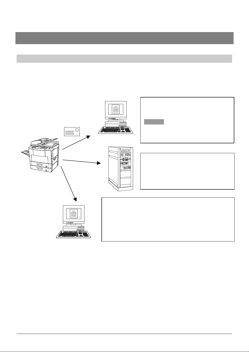
Chapter 1 Introduction
Overview
The AR-NS1 Network Scanner Expansion Kit incorporates a network scanner function into Sharp
Digital Copiers. With this added scanning functionality, printed information such as photos, paper
documents, or plain text can be scanned and distributed over a Local Area Network (LAN), Intranet,
or Internet. Three destination methods are available and are listed below.
1. Scanned information can be emailed to
recipients. (Throughout this manual, this
function is referred to as “Scan to E-mail.”)
CAUTION
Prior to the use of the Scan to E-mail, refer
to page 36 to 37.
2. Scanned information can be sent to a
designated directory on an FTP server
over a network. (Throughout this manual,
this function is referred to as “Scan to
FTP.”)
3. Scanned information can be sent to a specified PC
Desktop. (Throughout this manual, this function is
referred to as “Scan to Desktop.”)
In order to use this functionality, you must first install the
Sharpdesk and Network Scanner Tool software
programs. (See page 26 for more information.)
Note that the scanned data or error message destinations can only be set up using a standard web
browser (Netscape Navigator 4.0 or Internet Explorer 4.0 or later versions) installed on a personal
computer connected to a network. These destinations can not be set up using the front panel of
Sharp Digital Copiers. See page 6 for further information.
1
Page 6

Chapter 1 Introduction
Basic Theory of Operation
The following major components make up Sharp’s network scanning system.
Sharp Supplied Components:
•
AR Series Digital Copier
•
AR-PB2A printer board (installed in the copier) with 48 MB memory in total (standard 16MB).
•
AR-NC3D network interface card (installed in the copier)
•
AR-NS1 network scanner expansion kit
•
AR-NS1 network scanner utilities (CD-ROM) with Sharpdesk desktop document management
software, Network Scanner Tool, etc.
Network Components:
•
E-mail Server (only required for “Scan to E-mail” functionality)
•
FTP Servers (only required for “Scan to FTP” functionality)
•
Personal Computers (required for “Scan to Desktop” functionality and others)
Identifying the Copier’s Network Address
To begin setting up your network scanning system, you must first identify the designated
copier(s) network address (IP address). This address is the same one as set in the Printer
Expansion Kit AR-PB2A which can be found in the copier’s operation panel Printer
Configuration page. To access the Printer Configuration page:
1. Touch the PRINT key on the copier’s operation panel.
2. Select OFFLINE.
3. Touch the MENU key.
4. Select PRINT TEST PAGE.
5. Select PRINT CONFIGURATION PAGE.
The copier prints out the Printer Configuration page.
2
Page 7

Chapter 2 Getting Started
This chapter describes the network scanning configuration procedures that dealer service or
customer MIS personnel need to perform prior to using Sharp’s network scanning system. Such
procedures involve three steps.
1. Password Setting
Setting up the administrator’s and user’s passwords for this software.
NOTE
The administrator of this software can set the passwords (for administrator and user) to authorize
the access to the Web pages such as E-mail Setup and Network Scanning Setup or Network
Scanner Management for the security of the settings on the pages. If such a security measure is
not required, the Password Setting procedure can be skipped. This will leave Web access
settings open to all users.
2. E-mail Setup and Network Scanning Setup
Configuration of the network scanning system and status & alert by E-mail.
3. Scanning Destination Setup
Setting the default scanning parameters on the device to send the scanned image or data as
Destinations.
NOTE
For the settings made by accessing the Web pages, such as E-mail Setup and Network Scanning
Setup, the following characters can not be input in the pages:
* Characters that cannot be input: < > & "
* Examples of improper input: <abc> <abc "abc" "abc abc" < >
The input is case-sensitive.
Password Setting
The administrator should exclusively do the setting of the password of two levels: User and Admin
when setting up network scanning system security. A User password is required to create, change,
and delete destinations. An Admin Password lets you access to the same functions as the User
password but is also required to set system configuration settings such as:
•
Password Setup page
•
E-mail Setup and Network Scanning Setup page
•
Setup Status and Alerts by E-mail pages
When you first install your network scanning system, both password functions are disabled. To set a
User and/or Admin password the administrator is requested to follow the steps below:
Open the web browser such as Netscape Navigator 4.0 and later or Internet Explorer 4.0 and
1
later.
Input the IP Address previously specified to the ADDRESS field of the browser.
2
Input the IP address specified in the printer expansion kit AR-PB2A. (For checking the IP address, refer to
the part of “Identifying the Copier’s Network Address” on page 2.) When the connection is completed, the
Machine Information Page will be displayed.
3
Page 8
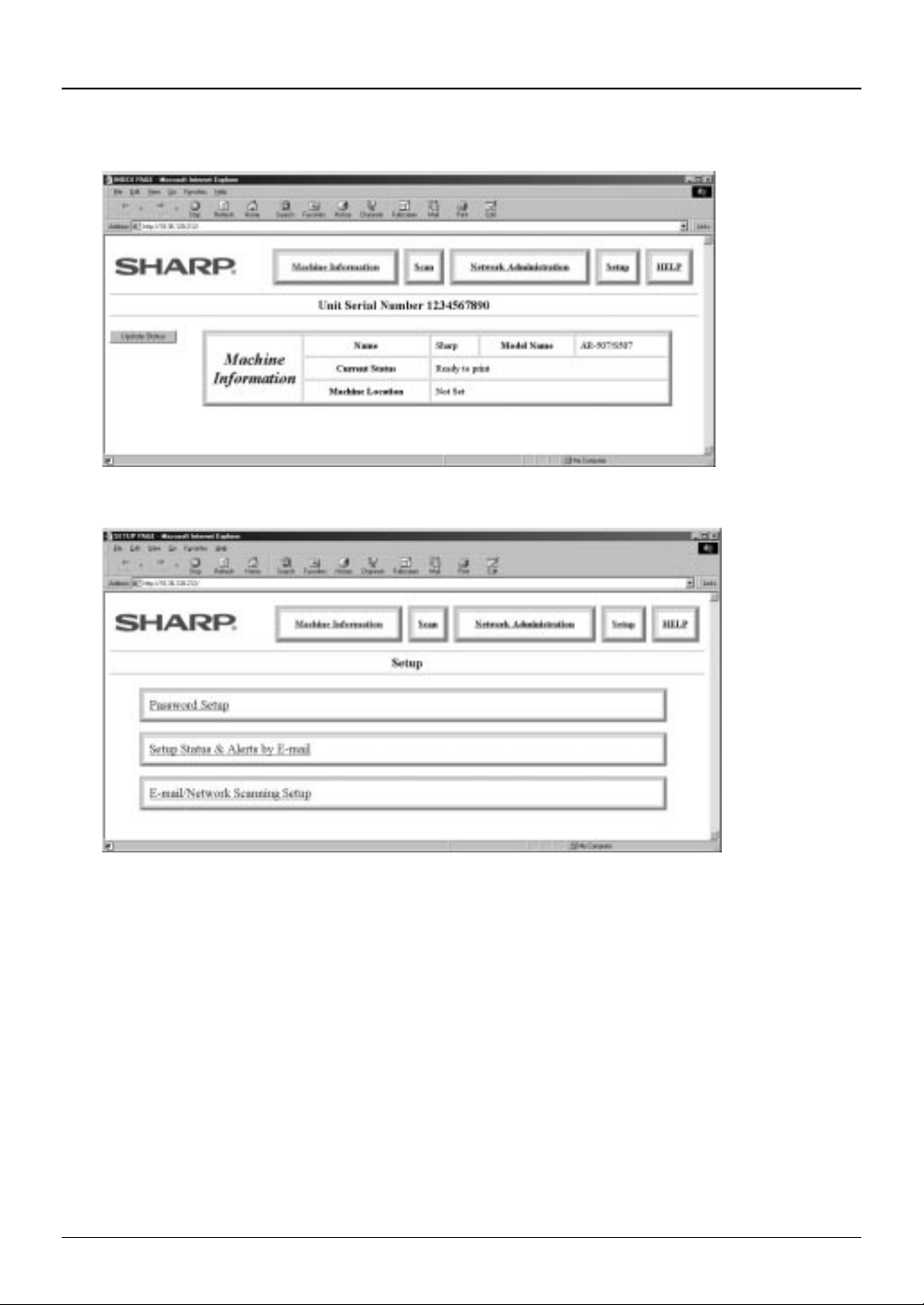
Chapter 2 Getting Started
From the SharpHTTP Home page, click the Setup button.
3
Click on Password Setup button. This brings up the Password Setup web page.
4
4
Page 9
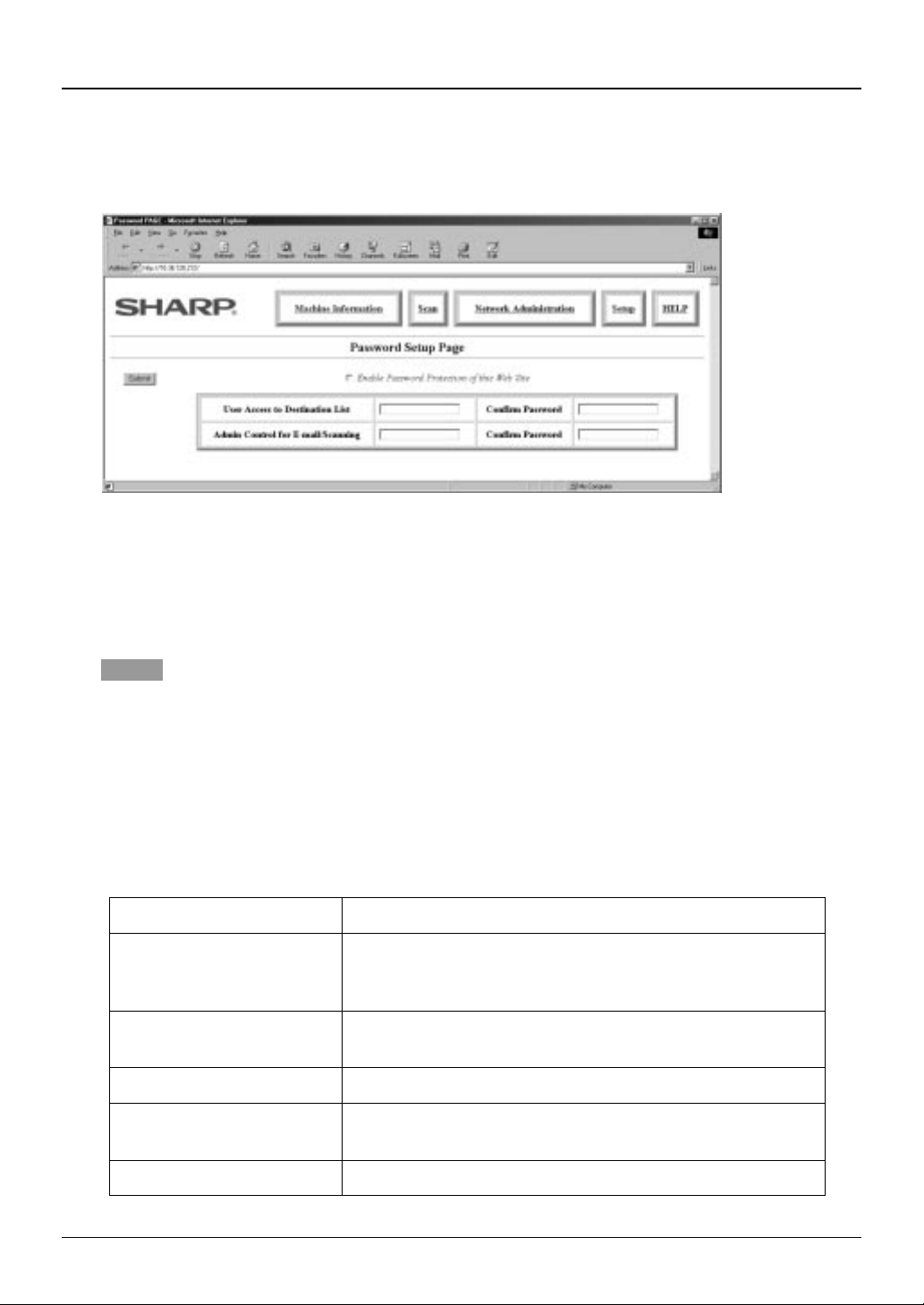
Chapter 2 Getting Started
This page lets the system administrator select passwords for the entire web site (refer to the
5
following Table). Key in a user password in the User Access to Destination List field and/or an
administrator password in the Admin Control for E-mail/Scanning field.
One password for each User and Admin respectively can be registered. After entering the passwords in
both the entry and confirm locations for User and Admin, check the box of Enable Password Protection of
this Web Site and click the Submit button to register the passwords.
If you enable the password protection with entering neither User nor Admin password, the password
"Sharp" will automatically be entered.
NOTES
1. Password input is case sensitive (lowercase and uppercase characters are distinguished).
2. Both passwords need to be entered prior to submitting. If only one password is entered and confirmed
the other will default to “Sharp” after submitting.
3. The passwords must be confirmed by entering in both fields of “User Access to Destination List” and
“Confirm Password” for the user password and “Admin Control for E-mail/Scanning” and “Confirm
Password” for the administrator password, and then select the Submit button to register the passwords.
Once the passwords have been registered, you will be prompted for user name and password
every time you try to enter the web pages of the network scanning system. The user names will
always be “user” for user level and “admin” for administrator level.
Name Definition
Enable Password
Protection of this Web Site
To enable password protection, check the box and click
the Submit button. To disable it, clear the check mark in
the box and click the Submit button.
User Access to
Enter a User password within 10 characters.
Destination List
Confirm Password Enter the User password again to confirm it.
Admin Control for E-
Enter an Admin password within 10 characters.
mail/Scanning
Confirm Password Enter the Admin password again to confirm it.
5
Page 10
Chapter 2 Getting Started
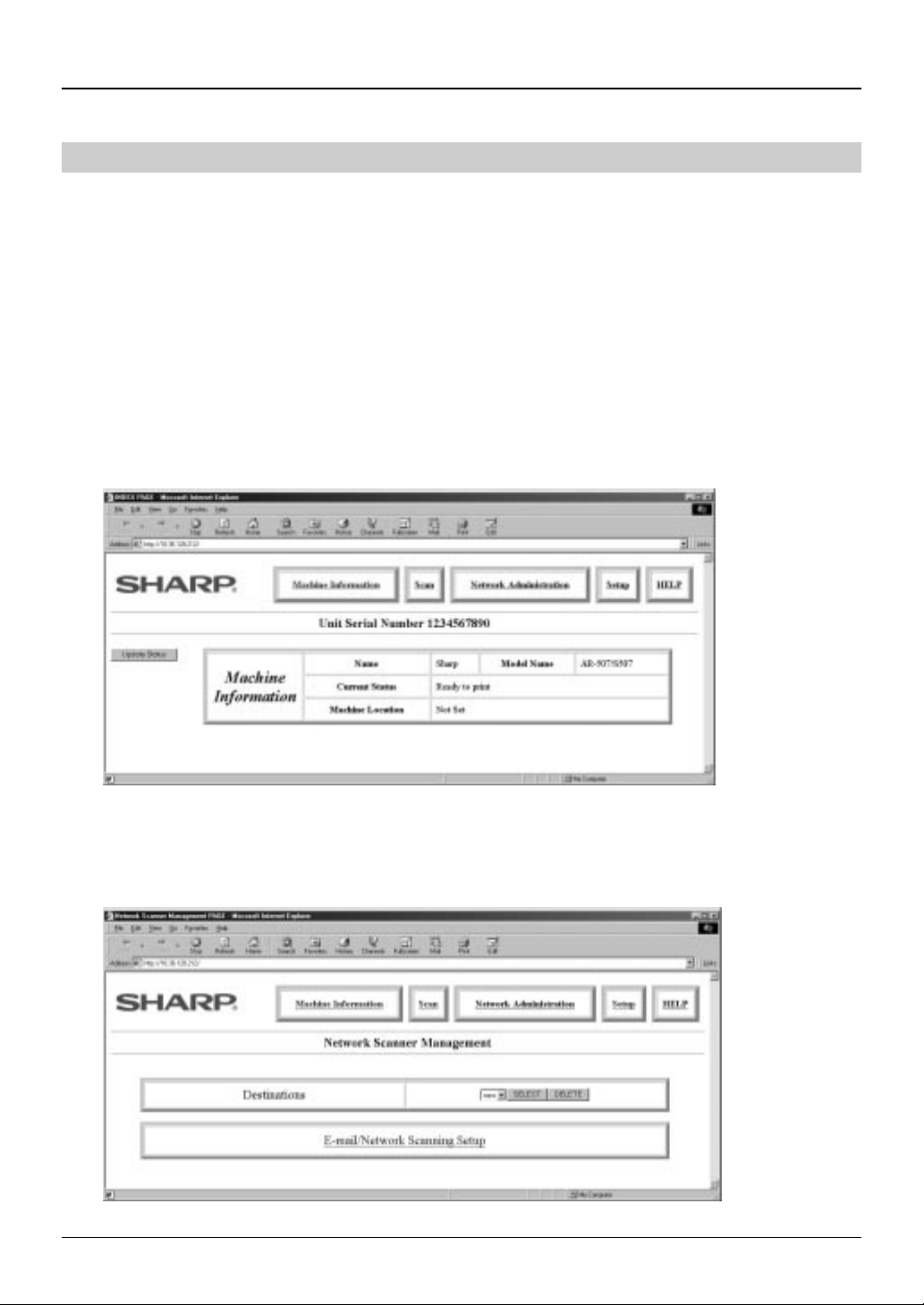
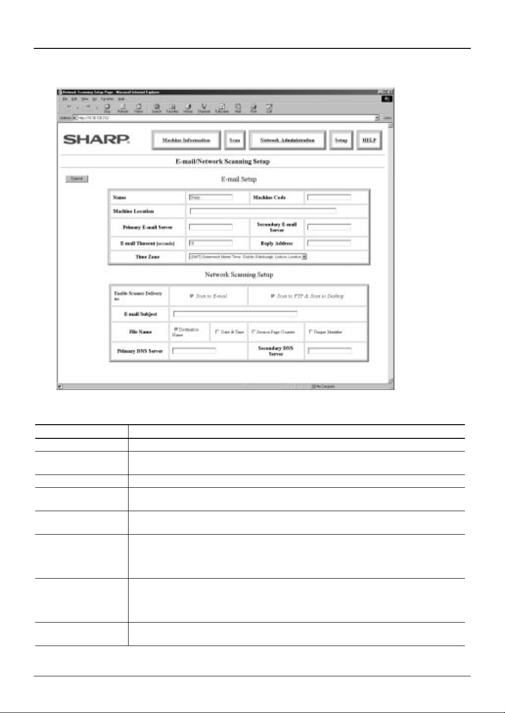
E-mail Setup and Network Scanning Setup
This section describes how to set up the basic status of the e-mail sending including the definition of
the file names for the image data to be attached and so on, and how to set up Network Scanning. In
the E-mail scanning destination, SMTP (Simple Mail Transfer Protocol) protocol is used to send the
e-mails. Such settings must be effected by the system administrator who has the special network
related backgrounds.
Open a web browser such as Netscape Navigator 4.0 and later or Internet Explorer 4.0 and
1
later.
Input the IP Address previously specified to the ADDRESS field of the browser.
2
Input the IP address specified in the printer expansion kit AR-PB2A. (For checking the IP address, refer to
the part of “Identifying the Copier’s Network Address” on page 2.)
When the connection is completed, the Machine Information Page shown below will be displayed. This
page displays a navigation bar for accessing other internal web pages that allows to get overall device
status information .
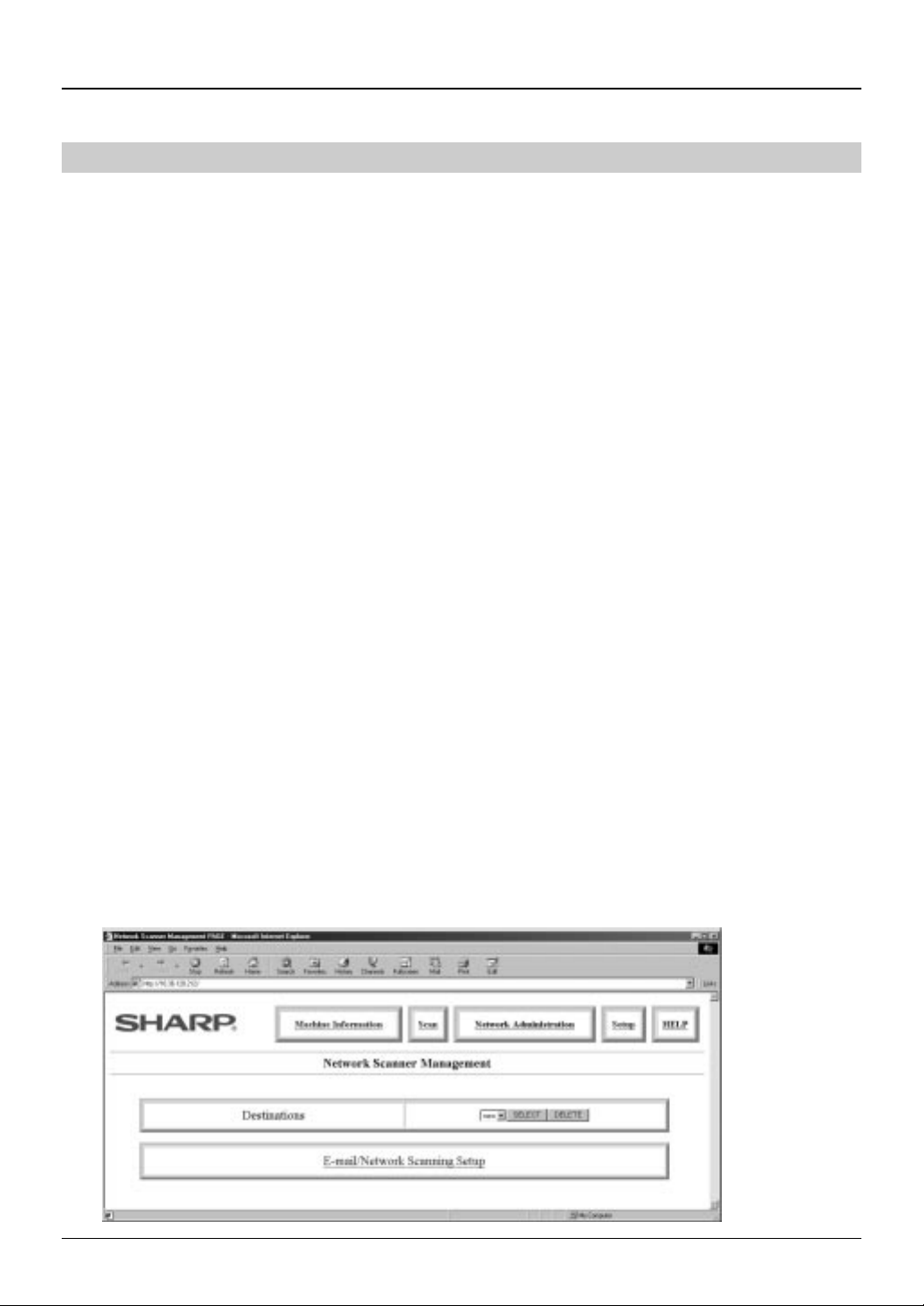
Click on the Scan button.
3
This brings up the Network Scanning Management web page. This page functions as main
page for adding, deleting and modifying scanning destinations.
Click on the E-mail/Network Scanning Setup button.
4
6
Page 11
Chapter 2 Getting Started
g
g
This brings up the E-mail/Network Scanning Setup web page. From this page you can make
5
changes to the items as listed in the following table:
E-mail Setup
Item Description
Name Enter a unique name for the machine within 50 characters.
Machine Code
Machine Location Enter a unique entry for the machine location within 100 characters.
Primary E-mail
Server (*1)
Secondary
E-mail Server
E-mail Time Out
Reply Address (*2)
Time Zone
This field is not used with normal use. Some kind of software may use this
field to identify the machine.
Enter an IP address for the primary e-mail server or a host name.
Enter an IP address for the secondary e-mail server or a host name. No
need to enter if secondary e-mail server is not set up.
Enter a time out period, from 0-60 seconds, that the system will wait for as
it attempts to connect to the primary server. The default is 20 seconds. If no
connection is made, the system will then look for the secondary server if it
has been set up. If not, the system will stop attempting to connect.
Enter an e-mail address to which the machine returns an unsuccessful
delivery messa
can be entered. The entered e-mail address is also used as sender e-mail
address.
Select the time zone of the place to use this Network Scannin
specific time zone is set after the selection.
*1. 2.: If no e-mail server is used on your network, enter “0” in this field.
e when the distribution has failed. Only 1 e-mail address
7
System. A
Page 12

Chapter 2 Getting Started
Network Scanning Setup
Item Description
Enable Scanner
Delivery to:
Check on the check box of the preferred scanning destinations to send the
scanned image data. If the check mark is cleared, the copier’s touch panel
does not show any Destination Name of the selected destination type on it.
E-mail Subject
Enter an e-mail subject message when using the E-mail Destination within 80
characters.
File Name File names for e-mail notification and files on the FTP server are
automatically constructed from selected elements. Elements are selected by
checking their bo xes. The left most selection will be the f irst element in the
name. Destination Name is checked in the default setting. If none of the
boxes is checked, the file name will be the extension only (.tif or .pdf). As
such name might incur an unexpected operation depending on the recipient
operation system or mailer software, make sure to check either of the boxes.
Destination Name and Date & Time are derived from current information.
Session Page Counter is also derived from current machine information but is
reset at machine power-up. The Unique Identifier selection ensures a unique
file name by incorporating the machine’s serial number, the counter number
and the date and time. In case of sending the same data to the same
recipient various times, it is recommended to check the Identifier box to avoid
the data overwrit in g with t h e same file nam e.
Primary DNS
Server Address
(This is required if you are using DNS host name.) Enter an IP address for
the primary DNS server within 15 characters. The entry format is
“XXX.XXX.XXX.XXX”
Secondary DNS
Service Address
(This is required if you are using DNS host name.) Enter an IP address for
the secondary DNS server within 15 characters. The entry format is
“XXX.XXX.XXX.XXX”
NOTE
If nothing is input in the fields of the Primary E-mail Server and the Reply Address of the E-mail Setup menu
(see page 7), the check mark position of the File Name can not be changed. To change the File Name setting
when the aforementioned two fields are left blank in such a case that the Scan to E-mail is not selected, input
“0” as a dummy to both fields.
8
Page 13
Chapter 2 Getting Started
Scanning Destination Setup
This section describes how to set up each of the following scanning destinations:
•
E-mail
•
FTP Server
•
Desktop
To send the scanned image by the network scanner, the necessary information such as the address
of the recipient must be registered as destination. Once registered, the destination is displayed as a
selectable button on the touch panel of the digital copier.
1. E-mail and FTP Server scanning destination: Set up by accessing the SharpHTTP homepage in
the embedded web server of the copier via the web browser from your network connected PC
(see the processes shown below).
2. Desktop scanning destination: It is recommended to set up by using the Setup Wizard of the
Network Scanner Tool, which is optionally installed at the installation of the Sharpdesk. (See
page 27.)
Nevertheless, it is also possible to create, modify or delete the Desktop Destinations by
accessing the embedded web server of the copier via the web browser from your network
connected PC.
Open the web browser such as Netscape Navigator 4.0 and later or Internet Explorer 4.0 and
1
later.
Input the IP Address previously specified to the ADDRESS field of the browser.
2
Input the IP address specified in the printer expansion kit AR-PB2A. (For checking the IP address, refer to
the part of “Identifying the Copier’s Network Address” on page 2.)
When the connection is completed, the Machine Information Page shown in the step 2 of page 6 will be
displayed. This page displays a navigation bar for accessing other internal web pages that allows to get
overall device status information.
Click the Scan button.
3
This brings up the Network Scanning Management web page. This page functions as main page for
adding, deleting and modifying scanning destinations.
Click the SELECT button of the Destinations.
4
9
Page 14
Chapter 2 Getting Started
NOTE
To make a new destination entry, click the SELECT button with “new” word shown in the left box of the
*
SELECT button. For the correction or deletion of the registered destination, select the target destination
and click the SELECT button (DELETE button in case of the deletion).
*To delete a destination, confirm that the destination is not shown in the copier’s touch panel. The
destination shown in the touch panel can not be deleted.
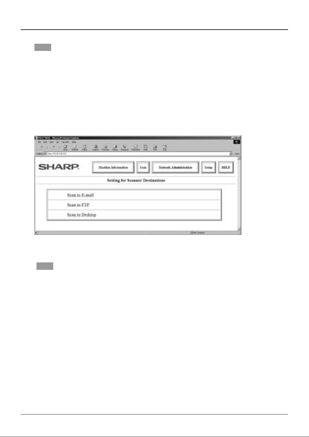
When entering a new destination, the Destination Setup page (shown in the step 5 below) is shown.
When correcting a destination once entered, the setup page for the selected destination comes out and
when deleting a destination, the confirmation page for the deletion appears. (The step 5 below is not
required for the correction and deletion of the existing destination.)
This brings up the Scanner Destinations web page. Using this screen, choose the button as
5
required destination.
NOTE
As for the next steps, follow the descriptions of each destination.
10
Page 15
Chapter 2 Getting Started
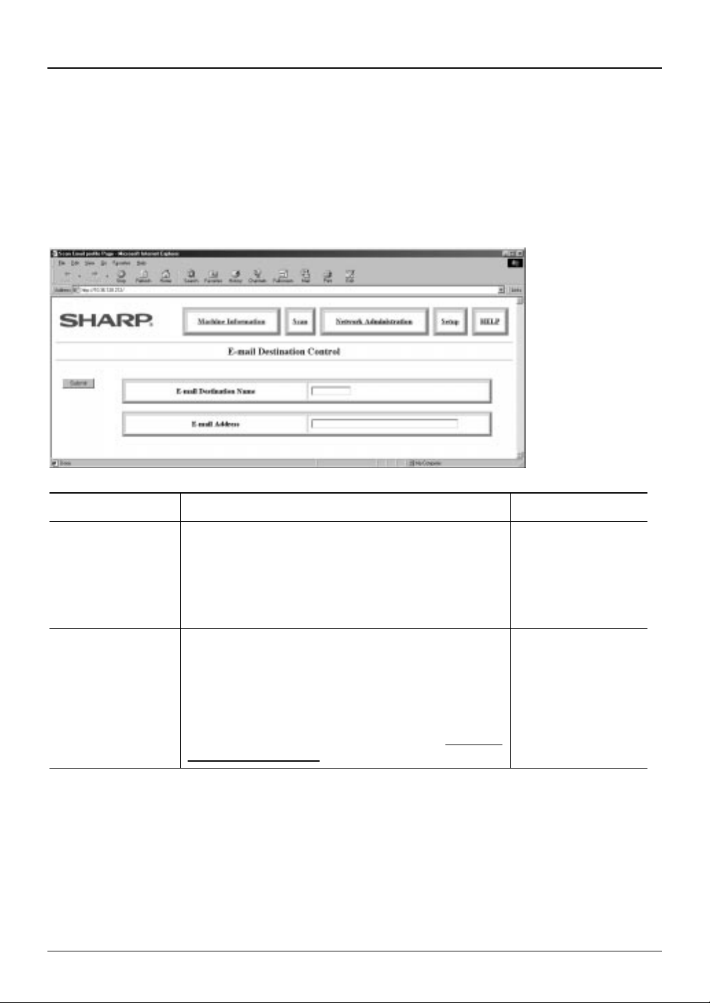
Setting up E-mail Destinations
E-mail Destinations are defined on the E-mail Destination Control page. To set up this scanning
destination, enter information in the fields according to the parameters listed in the table that follows
the E-mail Destination Control page. After entering all the necessary information, click the Submit
button to add the destination and return to the Network Scanner Management page. Around 100
destinations (*1) can be registered in conjunction with the other 2 kinds of destination.
You can now access this destination from the front panel of the copier.
Item Description Default
E-mail Destination
Name
E-mail Address Unlimited character field to enter multiple e-mail
Input the destination name here with up to 18character per destination name. The name input
here is displayed on the touch panel screen of the
copier. Do not enter the destination name here
which is already registered (especially the one
registered for the other 2 kinds of destination).
addresses of the destination. Multiple addresses
can be entered by separating with standard e-mail
name separator of your e-mail system (*2). Some
systems use a comma “,” or a semi-colon “;”.
Nicknames can not be entered here. Use fully
qualified email destination names. Example:
user@sharp-usa.com
*1. 2.: When multiple addresses are entered by using a single E-mail
Destination, the number of the registered destination may be less
than 100.
Text
Unlimited number
of e-mail addresses
11
Page 16

Chapter 2 Getting Started
Setting up FTP Server Destinations
FTP Destinations are defined on the FTP Destination Control Page. To set up this scanning
destination, enter information in the fields according to the parameters listed in the table that follows
the FTP Destination Control page. After entering all the necessary information, click the Submit
button to add the destination and return to the Network Scanner Management page. Around 100
destinations (see *1. & 2. of page 11) can be stored in conjunction with those of the other 2 kinds of
destination.
You can now access this destination from the front panel of the copier.
Item Description Default
FTP Destination
Name
Host Name or IP
Address
FTP User Name
(can be omitted.)
Password
(can be omitted.)
Directory
(can be omitted.)
Enable E-mail
Hyperlink Check
Box and E-mail
Address
Input the destination name here with up to 18-character per
destination name. The name input here is displayed on the
touch panel screen of the copier. Do not enter the
destination name here which is already registered
(especially the one registered for the other 2 kinds of
destination).
Character field for the FTP server name either as an IP
address or a host name.
Character field for the FTP user name within 50 characters.
Character field for the FTP password within 50 characters.
Character field to specify a directory on the FTP server
within 200 characters.
Notifies the recipient of a file with an e-mail that the file on
the FTP server is sent. For notifying, input the e-mail
address of the recipient here and check the check box. The
recipient FTP server name is described in the hyperlink
format on the e-mail.
12
Unchecked
Page 17

Chapter 2 Getting Started
Setting up Desktop Destination Con t rol
When you press the Scan to Desktop button in the step 5 of page 10, the screen shown below
appears. As the Desktop Destination Control for the Scan to Desktop is to be set up when
Sharpdesk (Network Scanner Tool) is installed (or after the installation) in the destination PC as
described on page 27, you do not need to set it up again in this screen. In such a case, however,
as you add another digital copier equipped with the AR-NS1 in the same network to do the
Scan to Desktop to the same destination registered in the current digital copier, you should
set up the Desktop Destinations from this page.
For the setting, select the desired Destination for the Scan to Desktop in the step 4 of page 9 and enter the
same contents of the screen, then the setting screen, shown below, of the added machine appears. When you
have entered all the items, click the Submit button to register the information. If you have multiple Destinations
to transfer, repeat these steps by necessary times. Around 100 destinations
stored in conjunction with the other 2 Destinations.
(see *1. & 2. of page 11)
can be
Item Description
Desktop Destination
Name
Enter a name of the destination to be registered here. The name appears on
the copier’s front panel. Do not enter the destination name here which is
already registered (especially the one registered for the other 2 kinds of
destination).
Host Name or IP
Address
Enter the IP address or DNS name of the destination PC here. (When DNS
name is entered, a DNS server is required to have been set in the E-mail
Setup/Network Scanning Setup screen (see page 7).
Desktop Port
Number
Enter a port number to be used for data transfer on the destination PC here.
(The default port number is set to 21.)
Process Directory Enter the process directory name set in the destination PC here. A pr ocess,
which is to be automatically run upon arrival at the destination PC, has been
assigned to this directory. If no process directory is entered, Sharpdesk
Desktop will be launched automatically. (See step 3 of page 30.)
NOTE
Entering (and correcting or deleting) of a Desktop Destination Control can be done by using the Setup Wizard
of the Network Scanner Tool, which is optionally installed at the installation of the Sharpdesk. (See page 27.)
Nevertheless, deleting of the stored Desktop Destinations can also be done from the Network Scanner
Management web page. (Refer to the step 4 of page 9.)
13
Page 18

Chapter 3 Using the N etwork Scanner
This chapter describes how to use the network scanning system from the front panel of the copier.
The network scanning system lets you convert printed information such as paper documents, or
plain text into image data and distribute this data over a Local Area Network (LAN), Intranet, or
Internet.
To send the original image using the network scanning system, select a destination from the front
panel (touch panel) of the copier. See page 10 for information on how to locate a destination.
Following three destination types are available.
1. Send a scanned image to an email recipient (Scan to E-mail).
2. Send a scanned image to a designated directory on the FTP server (Scan to File).
3. Send a scanned image to a PC’s desktop (Scan to Desktop).
Prior to sending an image, several settings such as duplex scanning, image size, resolution, type of
scanned image format, or file compression format can be made.
Scan to E-Mail
Scan to FTP
Scan to Desktop
NOTE
In order to use the Scan to Desktop functionality, you must first install the Sharpdesk and Network Scanner
Tool software programs.
CAUTION
The size of the scanned image may become huge depending on the scan resolution or the data format. When
you send the image data attached to e-mail using the Scan to E-mail, exercise care for the file size not to
exceed the capacity authorized by the network administrator. See page 36 to 37.
1
Place the document in the RADF or RSPF, or on the document glass of the copier.
NOTE
A document smaller than A5 (5-1/2” x 8-1/2”) might not
be appropriately displayed in the paper select display or
it might not be displayed at all.
When scanning 2-sided originals by using the RADF or
RSPF, you must set up the original style beforehand in
the Original Setting procedures. (See page 19.)
14
Page 19

Chapter 3 Using the Network Scanner
2
Touch the SCAN key.
3
If necessary, select QUALITY/FORMAT/ORIGINAL, otherwise, proceed to step 4. See page 17
for instruction on this setting method.
4
Touch the DESTINATION LIST key.
5
Select a destination by touching a key showing the desired destination on the screen. To select
the Scan to FTP or Scan to Desktop, touch the corresponding tab.
The display can be changed by touching the or
key.
NOTE
For the Scan to Desktop function, Network Scanner Tool
must be installed and properly configured.
15
Page 20

Chapter 3 Using the Network Scanner
C
CLEAR
INTERRUPT
CA
CLEAR ALL
START
6
Touch the key.
The following screen appears.
Only one destination can be selected at a time. When
sending to multiple destinations, repeat steps 4 through
6 for each destination.
7
Press the START key.
When using the RADF or RSPF, sending starts after all the originals have been scanned.
From the document glass, only one page at a time can be sent. When you send multiple-page
documents, repeat the steps replacing the original on the document glass (in case of 2-sided
originals, reversing the face of the original) and press the START key by the necessary times
before the auto clear functions, which is set in the copier’s Key Operator Program (the factory
default setting is 60 seconds). If the auto clear has functioned during the scanning, you need to
newly repeat the above steps 4 to 7.
16
Page 21

Chapter 3 Using the Network Scanner
Scanning Setting
You can select following 3 types of setting for the scanning:
•
Quality Setting Includes original image type selection, intensity adjustment, contrast
adjustment and resolution selection.
•
Format Setting Includes selection of scanned image file type, compression format and file
composition (making single-page files or whole pages into one file).
•
Original Setting Includes document style selection and desired scan size selection.
Quality Setting
1
Touch the QUALITY key.
2
When selecting the Original Image Type, select TEXT or TEXT/PHOTO mode depending on the
original image type.
TEXT Original with normal text
TEXT/PHOTO Original mixed with text and photo
3
To adjust intensity, touch the DARKNESS key to decrease or the DARKNESS key
to increase.
4
To adjust contrast, touch the CONTRAST key to decrease or the CONTRAST key
to increase. Note that if TEXT mode is selected in step 2, contrast can not be adjusted.
5
To adjust resolution, select either of the resolution buttons, 200 dpi, 300 dpi or 600 dpi.
6
Touch the OK key.
17
Page 22

Chapter 3 Using the Network Scanner
Format Setting
1
Touch the FORMAT key.
2
Select the file type and compression format to generate the image data from the scanned
image.
The file type for the generated image data can be either TIFF or PDF. The compression format
can be: G4, G3-1d and UNCOMPRESSED for TIFF; G4 and G3-1d for PDF.
NOTE
To open the scanned image without using Sharpdesk or Network Scanner Tool, you need to have viewer
software installed that supports the selected image type (format). In the initial settings, the image type
(format) that makes the file size the smallest is the default. If you can not open the image file, changing the
image format to send might solve the problem.
3
Select the File Composition of the Image Data.
When scanning multiple pages, you can select to save them consolidated as a single file or
divided into a number of single-page files. When the box of ONE PAGE PER FILE is checked,
multiple-page documents are delivered as single-page files. When unchecked, they are
delivered as a consolidated multiple-page file.
4
Touch the OK key.
18
Page 23

Chapter 3 Using the Network Scanner
Original Setting
1
Touch the ORIGINAL key.
2
Touch the STYLE tab to select the original style.
Select 1-SIDED, 2-SIDED BOOKLET or 2-SIDED TABLET in accordance with the original to be
scanned as shown.
2-sided Booklet 2-sided Tablet
Binding edge
A
E
A B
C
G
Binding edge
When scanning A3(11” x 17”), B4(8-1/2” x 14”), or Legal size portrait originals, touch the
ROTATE THE IMAGE 90 DEGREES check box and then place the document in the orientation
shown in the following illu s tr a tion.
E F
NOTE
The above illustration shows the samples of portrait originals. Refer to page 21 “Image Orientation and
Original Placement Orientation” for how to place the originals on the document glass or in the document
feeder.
19
Page 24

Chapter 3 Using the Network Scanner
3
Setting the Desired Scan Size of Original:
The scan size of the original can also be set. For example, when using an A4 (8-1/2” x 11”)
original, a different area size such as B5 (7-1/4” x 10-1/2”) can be scanned. To set the scan
size, select a preset size in the AB or INCH tab, or enter a free size by selecting the CUSTOM
tab.
When selecting the preset sizes in the AB or INCH tab,
touch the AB or INCH tab to select the desired size key.
When entering free size, touch the CUSTOM tab and
then X and Y keys adjusting each size by using
and keys respectively.
The limit figures to be entered in the X and Y fields
are as follows:
XY
AB System
INCH
System
4
Touch the OK key.
NOTE
To cancel scan size, touch the AUTO key of SCAN AREA SELECTION. Afterwards, the scan size setting
is cancelled and the automatic size detection function is activated.
20
10 – 432mm 10 –297mm
1/2” – 17” 1/2” – 11-5/8”
Page 25

Chapter 3 Using the Network Scanner
Image Orientation and Original Placement Orietation
Place the original on the document glass or in the document feeder tray as shown below (the top
backward and the bottom frontward). If the original is placed in the different orientation, the image
data might not be properly displayed at the recipient’s location (upside-down or reversed short-edge
to long-edge, etc.).
On the Document Glass On the RADF or RSPF
Top
Bottom
Top
Bottom
Top
Bottom
Top
Bottom
NOTE
The above illustration shows the case of the
RADF. When using the RSPF, the original must
be placed face down with the same rotation.
21
Page 26

Chapter 4 Key Operator Program
This chapter describes how to customize your default scanner settings (resolution, file compression,
quality, format, document, etc.) using the key operator program. You can change settings such as
resolution, file compression, quality, format, and document by accessing the SCANNER DEFAULT
SETTING screen.
NOTE
For general information on accessing key operator programs, including registration of a key operator code
number or setting programs for copier features, refer to the copier’s Key Operator’s Guide.
Accessing the Scanner Default Setting Screen
You access the SCANNER DEFAULT SETTING screen in the same manner as you would other
copier settings (For general information, refer to the copier’s Key Operator’s Guide.). To access this
screen, follow the steps shown below from either the COPY mode or the PRINT mode.
1
Touch the key.
2
Touch the key.
22
Page 27

3
1
2 3
4 5
6
7
8
9
0
C
P
CLEAR
PROGRAM
AUDIT CLEAR
INTERRUPT
Using the numeric key, enter the key operator code (5 digits).
The dashes in the display change to asterisks as you
input the operator code numbers.
Chapter 4 Key Operator Program
4
Touch the key.
The SCANNER DEFAULT SETTING screen appears.
23
Page 28

Chapter 4 Key Operator Program
5
Touch the ESTABLISH NEW INITIAL SETTINGS key.
6
Touch the QUALITY, FORMAT, and ORIGINAL keys, in succession, to adjust the desired
settings.
7
Touch the OK key.
The settings made in the step 6 are now the new initial settings.
NOTE
To return the scanner mode settings to the their factory default status, touch the RETURN TO THE FACTORY
DEFAULT SETTINGS key described in step 5.
24
Page 29

Chapter 5 Network Scanner Utility CD-ROM
The AR-NS1 Network Scanner Utility CD-ROM contains the necessary files that let you install the
Sharpdesk and Network Scanner Tool software programs and gain access to their support
documentation with Software License Agreement.
Folder Composition List of Articles Explanation
VKDUSGHVN
PDQXDO
WULDO
DFUREDW
URRW
One set of the AR-NS1 contains a license for 10 users. If multiple users more than 10 intend to use
the contained software programs in the CD-ROM by installing them in their respective computers,
contact your authorized Sharp dealer.
NOTE
Some additional information, which is not included in this manual, can be found in the README file
and the User’s Guides of the CD-ROM.
AR-NS1 Client Soft Installer Installer for Sharpdesk and Network Scanner
Tool
User’s Guides Sharpdesk User’s Guide and Network
Scanner Tool User’s Guide
Type Reader Pro Ver. 5.0 trial Expert Vision company
Acrobat Reader
README Whole CD-ROM is explained.
Adobe Acrobat Reader Installer
System Requirements
Before installing the included software, make sure all PCs meet the following criteria:
PC
IBM PC/AT compatible mac h in e
CPU:
Pentium 100MHz or greater (Pentium 200MHz or greater recommended)
RAM:
More than 32MB (64MB or more recommended)
Required free disk drive space:
Video:
SVGA or higher, 256 colors or higher (True Color recommended)
Operating System
Microsoft Windows 95, WinSock2 required for Auto Detect function of Network Scanner Tool
Microsoft Windows 98
Microsoft Windows NT 4.0
Network Protocol
TCP/IP is required for Network Scanner Tool.
More than 80MB
(This includes a sample image and the help file)
Service Pack 4 required
.
25
Page 30

Chapter 5 Network Scanner Utility CD-ROM
Desktop Document Management Software; Sharpdesk
Sharpdesk lets you manage a variety of electronic information such as scanned image data from a
digital multi-function printer (MFP) or documents created using word processing or spreadsheet
application software. Some of the important features of Sharpdesk are:
• Sharpdesk works with your scanner to let you read paper documents into your PC using a fullfeatured set of scanning controls and options.
• Sharpdesk provides the network scanning options using Network Scanner Tool.
• Sharpdesk makes viewing of your images and documents quick and easy.
• Text image scanned into Sharpdesk can be converted into editable text for use with your favorite
word processor. Sharpdesk uses an advanced Optical Character Recognition (OCR) engine
that even preserves your document layouts.
• Distribute documents by e-mail or print a hard copy as easily as dragging a file onto an icon
on the Sharpdesk OutputZone.
Sharpdesk User’s Guid e
The Guide describes how to install, set up, and use the Sharpdesk software program. The Guide is
supplied as a Portable Document Format (PDF) document in CD.
Network Scanner Tool
Network Scanner Tool allows you to receive scanned images on your PC from a digital multifunction printer (MFP). It also configures the necessary settings to on the copier and client PC to
receive data. In addition, Network Scanner Tool will automatically start Sharpdesk upon receiving
image data.
The scanned image received by your computer can automatically be:
• Routed to folders
• Passed to applications with command-line
• Sent as e-mai l
• Pasted to Sharpdesk for Text conversion, Image processing and desktop document
management.
Network Scanner Tool User’s Guide
The Guide describes how to install, set up, and use the Network Scanner Tool software program.
The Guide is supplied as a Portable Document Format (PDF) document in CD.
26
Page 31

Chapter 5 Network Scanner Utility CD-ROM
Client Software Installation
This section provides installation procedures for Sharpdesk and Network Scanner Tool. Sharpdesk
and Network Scanner Tool are installed together automatically, unless instructed not to. For
additional Sharpdesk installation instructions, refer to Sharpdesk User’s Guide; for Network Scanner
Tool, refer to Network Scanner Tool User’s Guide.
Sharpdesk Install atio n
Installing the Sharpdesk software is a simple and straightforward process. When you install
Sharpdesk, Network Scanner Tool are loaded onto your PC together.
By default, the Sharpdesk software program is installed on your default boot drive (usually C:\) in a
folder named Sharpdesk (the full path is C:\Program Files\Sharp\ Sharpdesk\), unless you
specify another drive and/or folder during installation. The installation process also changes some of
your system files to allow all the Sharpdesk components to work properly.
You can also specify the location of where to store the files you work on in Sharpdesk. Unless
otherwise specified, the installation program creates a new Sharpdesk Deskto p folder and subfolders on the default boot drive (usually C:\). If you specify another location for your data files, you
should generally not assign them into the same folder (or sub-folder) as the Sharpdesk software,
since all Sharpdesk folders will be deleted if Sharpdesk software is ever un-installed.
Installing Sharpdesk
Sharpdesk can be installed using the Sharpdesk installation CD. To install from the Sharpdesk CD:
1. If any Windows applications are open, close them to ensure that the software installs
properly.
2. Insert the installation CD into your CD-ROM drive. Follow the on-screen instructions to
complete the installation process. If the screen does not appear (for example, because you
have disabled the Windows AutoRun feature), run the Setup.exe program from the CD.
3. The User Information screen appears first prompting to enter the Name, Company Name
and Serial Number fields. For the Serial Number, enter one of the Sharpdesk License
Numbers, which are printed on the front cover of this manual. Successively the “Software
License Agreement” screen appears. Read the description carefully. To install Sharpdesk,
you must accept this Agreement.
4. Once the installation completes, you might be prompted to restart your computer. If so
instructed, you must restart your computer in order to use the Sharpdesk software.
During installation or when restarting your computer, a folder is created in your Program Files
directory or the location you specified during installation that contains all the Sharpdesk software
files. You will also find a Sharp entry added to your Start/Programs menu containing the Sharpdesk
programs. Finally, a Sharpdesk shortcut is placed on your desktop making access to the software
very convenient.
27
Page 32

Chapter 5 Network Scanner Utility CD-ROM
Un-Installing Sha r p de s k
If you want to un-install Sha rpdesk, use your PC’s Add/Remove Pro grams ut ility located in Control
Panel. For more information, refer to your computer’s operating system documentation.
28
Page 33

Chapter 5 Network Scanner Utility CD-ROM
Network Scanner Tool Installation and Setup
Network Scanner Tool is installed with the Sharpdesk software installation, unless instructed not to.
The Network Scanner Tool automatically locates and configures all the configured network scanning
copiers on the network and then adds a Sharpdesk host that lets you store scanned images that are
received by your computer from a networked copier. The Sharpdesk also creates a Network
Scanner Tool entry in the Start/Program menu on your computer's desktop.
Before using Network Scanner Tool, you should set up Network Scanning by checking on the check
box of Scan to FTP & Scan to Desktop on the E-mail/Network Scanning Setup web page. (See page
7.)
For more information about the Sharpdesk and Network Scanner Tool, refer to the supplied
Sharpdesk User's Guide or the Network Scanner Tool on-line Help.
To set up a Desktop Destination using Network Scanner Tool use the Sharp Network Scanner
Setup Wizard (described below) or run Network Scanner Tool and set up a new link.
Reboot your computer. When the Sharp Network Scanner Tool Setup Wizard appears, click OK
1
after confirming that the copier is connected to the network. Set up Network Scanner Tool
following to the messages shown on the screen. If additional information is required, click the
Help button.
Enter the Process Definition Prefix, if necessary, and click Next>. Click Help for the detailed
2
information.
NOTE
Network Scanner Tools is shipped with 3 pre-define set of instructions called Process Definitions.
29
Page 34

Chapter 5 Network Scanner Utility CD-ROM
-Convert to Text
-Send to E-mail
-Sharpdesk Desktop
Process Definitions defines the instruction for how the image will be processed once it arrives at the
computer. These instructions included image correction, Optical Character Recognition (OCR), moving
the file to different directories, and launching applications. Additional Process Definitions can be created
by using the New… button
When you select one of the 3
Control Name will be a combination of this prefix and each
For example, if you enter the prefix “Sharp” and select “Send E-mail”
Destination Control Name displayed on the touch panel of the copier will be “Sharp-Send E-mail”. (With
this prefix, you can identify on the copier’s touch panel to which desktop destination should the file be
sent.)
Be careful, therefore, when changing the prefix not to use same prefix strings as those of other users.
Set up the
3
, which converts a scanned file to an editable document
, which launches your default e-mail applications so the file can be e-mailed.
, which launched Sharp Desktop applications. This is the default.
.
Process Definitions
Process Definition
and click the Next> button.
described in the next Step 3, the Desktop Destination
Process Definition
Process Definition
name.
, the Desktop
This screen allows you to preliminarily define how to process the received image data via the Desktop
Scanning Destination as next steps. For instance, you can let your mailer software start on receiving the
scanned data to send it attached to an e-mail message or let the OCR automatically convert it into the text
data. As the
Process Definition
can be modified later, you may leave it as the default setting at this stage.
30
Page 35

Chapter 5 Network Scanner Utility CD-ROM
Select the copier’s name to use as a network scanner and click the Next> button. The name
4
displayed are based upon the Machine Name set during the installation of the network
scanning function. See Page 7 “E-mail/Network Scanning Setup Web page” to change this
name.
When Windows 98 or Windows NT 4.0 with Service Pack 4 or later is used, the network connected copier
is automatically detected. The automatic detection is not available when Windows 95 is used ( the “Auto
Detect” button is disabled being grayed out.) Click on the New button and enter the IP address (For
checking the IP address, refer to the part of “Identifying the Copier’s Network Address” on page 2.) of the
copier to be used as a network scanner. Even when you use Windows 95, the automatic detection will be
available if you update Winsock2 (Windows Socket 2). (See page 20 of the Operation Manual for the ARPB2A Printer Expansion Kit for the additional information about how to update it.)
The setting in the above steps 3 and 4 can be modified later. For the modification, click the Windows Start
button, then Program and then Sharpdesk and finally Network Scanner Tool Configuration. For the
detailed information about such settings, refer the on-line Help or the Network Scanner Tool User’s Guide
contained in the supplied CD-ROM.
31
Page 36

Chapter 5 Network Scanner Utility CD-ROM
When the completion screen message appears, click the Finish button.
5
32
Page 37

Chapter 6 Troubleshooting
When problems or questions arise with regard to copier operation, try to solve the situation using the
information listed in the following troubleshooting entries. If problems still persist, contact your
authorized Sharp Service Center for further instructions.
Problem: Cannot scan the image.
Check: Is the original correctly placed on the copier glass or in the document feeder tray?
Solution: Place the original face down on the document glass. When using the document feeder,
place face down in case of the RSPF and face up in case of the RADF.
If the Scanning function is not available even though the “SCAN” key is touched, contact
your authorized dealer of Sharp for technical support.
Problem: A moiré (stripe pattern) appears on the scanned image.
Check: Is the scan resolution properly set?
Solution: Change the scan resolution. Also, changing the original document placement position or
angle might reduce the appearance of moiré.
Problem: Scanned image is fuzzy or has smudges.
Check: Is the copier document glass or document cover clean?
Solution: Clean the document glass or document cover following the instructions in the supplied
copier operation manual.
Problem: Scanned image becomes clipped.
Check: Is the scanning size set smaller than the original size?
Solution: Set the actual original size. (See page 14.)
If the scanning size is intentionally set smaller than the actual original size, place the
original taking into account the reference position. For example, when scanning an A4
(8-1/2” x 11”) size original with a B5 (7-1/4” x 10-1/2”) scanning size on the document
glass, align the original using the scale at the left edge to fit the area to be scanned
within the B5 (7-1/4” x 10-1/2”) original guidelines.
Problem: Scanned image is upside down or in wrong orientation.
Check: Is the original properly placed in the right orientation?
Solution: Place the original in the right orientation. (See page 21.)
Problem: Scanned image of the opposite side of the original appears.
Check: Is the original swapped left to right?
Solution: Place the original in the right orientation. (See page 21.)
33
Page 38

Chapter 6 Troubleshooting
Problem: Can not open the image data at the recipient computer.
Check: The software installed at the recipient computer, such as viewer, is not associated with
the received image data format.
Solution: Change the file format (TIFF or PDF) and compression format (uncompressed, G3-1d
and G4) in the “Format Setting” for the destination. (See page 18.) Otherwise open it by
using the Sharpdesk or the software that accepts the file type and compression format.
Problem: Data sent does not reach the recipient.
Check: Is the data being sent to the right recipient? Is the registered address (e-mail address or
FTP address) correct?
Solution: Register and select the right recipient (address). (See page 11.)
* In case of unsuccessful data delivery when using e-mail (the Scan to E-mail), error
messages including undelivered message might be sent to the administrator’s e-mail
address previously designated. Check these error emails to determine the cause of
undelivered data. (See page 7.)
* When sending to the desktop, using the Scan to Desktop, Network Scanner Tool must
be installed. (See page 27.)
Problem: The data sent by e-mail (the Scan to E-mail) does not reach the recipient.
Check: The e-mail message might have exceeded the file size set by the system administrator.
When the e-mail message exceeds this size, it will not reach the recipient.
Solution: Reduce the email message file size (decrease the number of scanned pages). Contact
the system administrator to see if there is a file size limit for email messages.
Problem: Takes a long time to send an e-mail message.
Check: The larger the amount of the image data, the larger the file size. This can greatly
increase the amount of time it takes to send an e-mail message.
Solution: Set the appropriate resolution or compression level to meet the sending purpose, taking
into account the following settings to produce a well balanced image data between the
quality and the file size.
The ‘TEXT’ and the ‘TEXT/PHOTO’ mode
If the original does not contain a photo, illustration or other half tone image, select TEXT
mode to obtain a more practical image (especially for OCR). Use TEXT/PHOTO mode
when scanning an original that contains a photo or other half tone image if a priority is
set for the photo image quality.
Resolution
For a general text original, 200dpi or 300dpi resolution will produce a legible document
(200dpi is equivalent to a Fine Mode setting on a fax machine.)
Select 600dpi only when a higher-resolution image reproduction is required from detailed
originals such as those containing a photo, illustration or other half tone image. (OCR
requires 300dpi.)
Please note that the file size becomes larger if the higher resolution level is set. Also, if
the server does not have enough free disk space, or the system administrator sets a file
size limit, a large file might not reach the recipient. If this is the case, reduce the number
of pages to be scanned or decrease the scanning area on the original.
34
Page 39

Chapter 6 Troubleshooting
K
Problem: Cannot connect to the network.
Check: Network Interface Card (NIC) failed or is not properly connected.
Solution: Make sure the NIC is operating properly and is connected to the network cable. If the
problem persists, contact your system administrator or authorized Sharp Service Center
for further instructions.
Error Message at the Communication Error
When a communication error has occurred during the sending the scanned image data, the
following error message with an error code will appear in the display of the copier’s touch panel.
ERROR. PLEASE SEE YOUR DEVICE/NETWOR
ADMINISTRATOR. CODE: NN-NN
Error Code Table
Error Code Description of the Error
CE-01 An optional network interface card (Print Server Card) is not installed or out of order.
CE-02 Cannot find the specified mail server or FTP server.
CE-03 The server has been down during the scanning of the original.
CE-04 An invalid account name or password for the FTP server has been entered.
CE-05 An invalid directory of the FTP server has been entered.
CE-00 Other error than the above mentioned has occurred.
35
Page 40

Chapter 6 Troubleshooting
Special Remarks on Usin g the Scan to E-mail
Exercise care for the size of the scanned image not to be too large.
The maximum capacity allowed for the data in an e-mail via your mail server might be limited by
your system administrator. If a file size attached to an e-mail exceeds the limit when such a
limitation is effective, the data will not be transmitted to the destination. Even If you can send a
large-sized file without such a limitation, the recipient network might suffer some damage by the
heavy load including much longer receiving time of the data under some network (internet)
environment. Furthermore, continuous sending of the large-sized image data might give an
excessive load to the network, resulting in the total slowdown of the communications including the
other data or, at worst, the system down of the mail server or the network itself.
The guidelines of the image data size scanned by the AR-NS1 network scanner function are shown
as follows. Refer to them when you scan some originals.
In case of an A4 (8-1/2” X 11”) sized original image, the file size to be sent and the estimated
transmissio n time via the Scan to E-mail will b e a s descr ib e d in the fo llo wing c h art:
No. of
Resolution
When scanning the original
A with TEXT mode
File size : Transmission time File size : Transmission time
When scanning with the original
B with TEXT/PHOTO mode
original
300dpi Approx. 44KB : approx. 8 sec. Approx. 1340KB : approx. 36 sec.1
600dpi Approx. 84KB : approx. 11 sec. Approx. 5043KB : approx. 120 sec.
10
300dpi Approx. 441KB : approx. 33
sec.
600dpi Approx. 846KB : approx. 68
sec.
In this case, both file size and
transmission time become
excessive and not to be
recommended.
NOTE
File size:
of 10 originals are the ones when the 10 pages of scanned data are consolidated as a single file.
Transmission time:
the START key to its arrival at the first mail server. The figures in case of 10 originals are based on the
scanning via the document feeder. All the figures are the ones available in case of using a standard mail server
under the normal LAN environment. Refer to them as a guideline as the transmission time might considerably
vary with the environments.
The above figures are based on the image generated in the TIFF G4 format. And the figures in case
It describes the time required from the initiation of the image data scanning by touching
36
Page 41

Chapter 6 Troubleshooting
Original Image Samples
The samples shown below are just image samples for your easy reference to the descriptions in the
previous page and they are not the actual ones. (Their actual size should be A4 (8-1/2” X 11”) for
the figures shown in the previous page.)
Original Image A
Original Image B
37
Page 42

Chapter 7 Specifications
Model
Maximum Document Size
Maximum Scanning Pages per Job
Original Feeding Speed
(FPM : Face per Minute)
Page order for Multi-Page Document
Output Resolution
Scaling
Halftoning Process
Image Format and Compression
2-Sided Original
Scan Destinations
Supported SMTP server
Supported FTP server
System Setup
Supported Web Browser
Network Protocols
Mail Transfer Protocols
LAN Connectivity
Number of Destinations
AR-NS1
Depend on copier model and installed options
Up to 120 pages (up to 60 pages in case of scanning A4 [8-1/2”
x 11”] or larger size original at 600dpi resolution)
Depend on copier model and installed options
1 – N
Scan: 400dpi
Output: 200,300,600dpi
None
-Error Diffusion
(200/300/600dpi)
-TIFF
G.3-1d/G.4 /Uncompressed
-PDF
G.3-1d/G.4
Depend on copier model and installed options
To desktop (via FTP protocol)
To E-mail recipient (via SMTP protocol)
To File server (via FTP protocol)
SMTP compliant Mail systems
FTP compliant systems
Enabled via Embedded Web Server
-Internet Explorer 4.0 or later
-Netscape Navigator 4.0 or later
TCP/IP
SMTP
10Base-T
100Base-TX
Max. 100 destinations
(Maximum number of destinations would decrease depending on
the character volume of stored destinations.)
Specifications are subject to change without notice. Changes to the specifications will normally
reflect improvements or upgrades to AR-NS1 features and performance.
38
Page 43

Chapter 8 Glossary
Introduction
The following terms and definitions can assist you when working with the network scanning system.
A
ASCII
Acronym for American Standard Code for Information Interchange. A set of definitions for the bit composition of
characters and symbols. ASCII defines 128 symbols using 7 binary bits and 1 parity bit.
B
Browser
The application program, such as Microsoft’s Internet Explorer, that lets you display HTML documents.
D
Default Setting
A system setting incorporated at the factory and permanently registered to the application. Also, a value or a
setting that the software assumes until or unless you specify another value.
Devices
A device is a piece of hardware such as a scanner, printer, fax machine, digital camera or copier.
DPI
Dots per inch. A unit of measurement for indicating a printer’s resolution.
G
Graphic
A written, printed, or electronically displayed symbol or drawing. Also, characters or text that have been
generated by a computer graphics application program.
Grayscale
A color in black and white as a result of different intensities of black.
I
Image
Used interchangeably with Document. Commands and functions work exactly the same regardless of whether
the item in question is a .TIF file, or a .DOC file.
L
Landscape Orientation
The horizontal orientation of your document or image across the length of the page. The term landscape is
derived from pictures of the landscape, which are usually horizontal in format.
39
Page 44

Chapter 8 Grossary
O
OCR
Optical Character Recognition. A technology that lets you turn a paper document into an editable electronic
document.
P
Paper Feed
Movement of a sheet of paper into the printer’s paper path.
PC Fax
An electronic way to send and receive faxes from your computer. A PC fax is sent from or received by a
computer.
Portrait Orientation
The vertical orientation of your document or image across the width of the page (letter style). This is the
opposite of landscape orientation.
Printer Driver
Software that sends printing instructions to a printer. The printer driver keeps track of the attributes of a printer
and the codes a program must send to access those attributes.
T
TWAIN
Both a protocol and an application programmer’s interface (API) that lets you input image data directly from any
source (for example: desktop and handheld scanners, video capture boards, digital cameras, and other
imaging equipment) without requiring you to switch out of the application. It provides compatibility between
image input devices and applications by acting as the liaison between hardware devices and software
applications. Twain, the industry standard, was developed by the TWAIN working group which consists of
representatives from many leaders in the scanner hardware and software industry.
40
Page 45

Page 46

2000F DSC3
CINSE2012FC51
Page 47

Page 48

Chapter 8 Grossary
AR-NS1
SHARP CORPORATION
PRINTED IN JAPAN
2000F DSC3
CINSE2012FC51
 Loading...