

Page 1
CODE : 00ZARM207/A1E
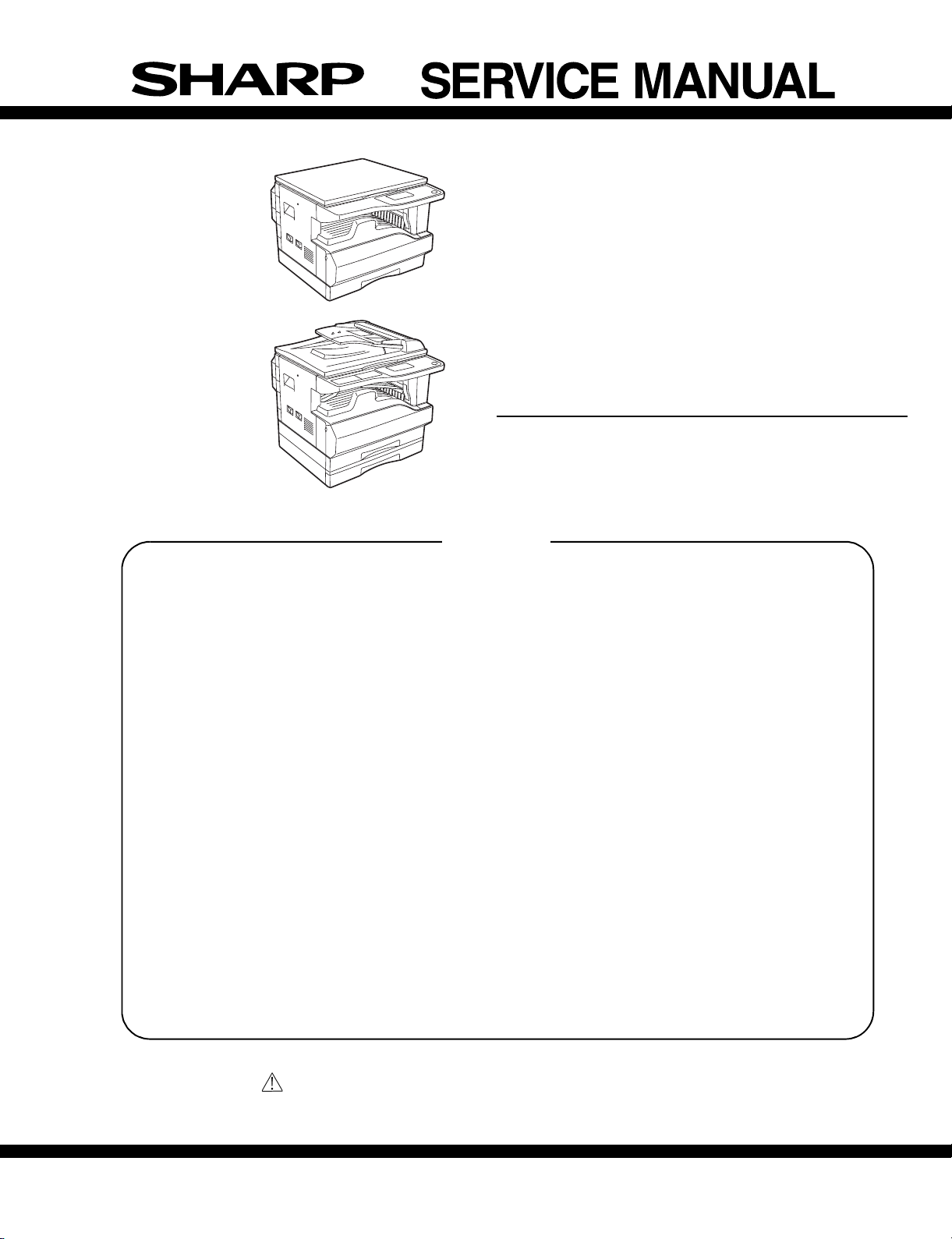
AR-M162
AR-M165
AR-M207
With the RSPF installed
[ 1 ] GENERAL. . . . . . . . . . . . . . . . . . . . . . . . . . . . . . . . . . . . . . . . . 1 - 1
[ 2 ] SPECIFICATIONS. . . . . . . . . . . . . . . . . . . . . . . . . . . . . . . . . . . 2 - 1
[ 3 ] CONSUMABLE PARTS. . . . . . . . . . . . . . . . . . . . . . . . . . . . . . . 3 - 1
[ 4 ] EXTERNAL VIEWS AND INTERNAL STRUCTURES . . . . . . . 4 - 1
DIGITAL COPIER
AR-M207
AR-M165
MODEL AR-M162
CONTENTS
[ 5 ] UNPACKING AND INSTALLATION . . . . . . . . . . . . . . . . . . . . . . 5 - 1
[ 6 ] ADJUSTMENTS . . . . . . . . . . . . . . . . . . . . . . . . . . . . . . . . . . . . 6 - 1
[ 7 ] SIMULATIONS . . . . . . . . . . . . . . . . . . . . . . . . . . . . . . . . . . . . . 7 - 1
[ 8 ] TROUBLE CODE LIST . . . . . . . . . . . . . . . . . . . . . . . . . . . . . . . 8 -1
[ 9 ] MAINTENANCE . . . . . . . . . . . . . . . . . . . . . . . . . . . . . . . . . . . . 9 - 1
[10] DISASSEMBLY AND ASSEMBLY. . . . . . . . . . . . . . . . . . . . . . 10 - 1
[11] KEY OPERATOR PROGRAM. . . . . . . . . . . . . . . . . . . . . . . . . 11 - 1
[12] FRASH ROM VERSION UP PROCEDURE . . . . . . . . . . . . . . 12 - 1
[13] ELECTRICAL SECTION . . . . . . . . . . . . . . . . . . . . . . . . . . . . . 13 - 1
Parts marked with “ “ are important for maintaining the safety of the set.
Be sure to replace these parts with specified ones for maintaining the safety and performance of the set.
SHARP CORPORATION
This document has been published to be used for
after sales service only.
The contents are subject to change without notice.
Page 2
Page 3

CONTENTS
[1] GENERAL
1. Cautions on using . . . . . . . . . . . . . . . . . . . . . . . . . . . . .1-1
2. Installation requirements . . . . . . . . . . . . . . . . . . . . . . . .1-1
3. Configuration . . . . . . . . . . . . . . . . . . . . . . . . . . . . . . . . .1-2
[2] SPECIFICATIONS
1. Basic specificatio n . . . . . . . . . . . . . . . . . . . . . . . . . . . . .2-1
[3] CONSUMABLE PA RTS
1. Supply system table. . . . . . . . . . . . . . . . . . . . . . . . . . . .3-1
2. Environmental conditions. . . . . . . . . . . . . . . . . . . . . . . .3-2
3. Production number identification . . . . . . . . . . . . . . . . . .3-2
[4] EXTERNAL VIEWS AND INTERNAL STRUCTURES
1. Appearance . . . . . . . . . . . . . . . . . . . . . . . . . . . . . . . . . .4-1
2. Internal. . . . . . . . . . . . . . . . . . . . . . . . . . . . . . . . . . . . . .4-2
3. Operation Panel. . . . . . . . . . . . . . . . . . . . . . . . . . . . . . .4-3
4. Display(base screen) . . . . . . . . . . . . . . . . . . . . . . . . . . .4-5
5. Motor, solenoid, clutch. . . . . . . . . . . . . . . . . . . . . . . . . .4-6
6. Sensor, switch . . . . . . . . . . . . . . . . . . . . . . . . . . . . . . . .4-7
7. PWB unit . . . . . . . . . . . . . . . . . . . . . . . . . . . . . . . . . . . .4-8
8. Cross sectional view . . . . . . . . . . . . . . . . . . . . . . . . . . .4-9
[5] UNPACKING AND INSTALLATION
1. Installing conditions . . . . . . . . . . . . . . . . . . . . . . . . . . . .5-1
2. Removal of protective material and fixing screw . . . . . .5-1
3. Installing procedure . . . . . . . . . . . . . . . . . . . . . . . . . . . .5-1
4. Removal and storage of fixing screw. . . . . . . . . . . . . . .5-2
5. Changing the paper size setting of a trey. . . . . . . . . . . .5-3
[6] ADJUSTMENTS
1. Adjustment item list . . . . . . . . . . . . . . . . . . . . . . . . . . . .6-1
2. Copier adjustment . . . . . . . . . . . . . . . . . . . . . . . . . . . . .6-1
[7] SIMULATIONS
1. Entering the simulation mode. . . . . . . . . . . . . . . . . . . . .7-1
2. Canceling the simulat i o n mode . . . . . . . . . . . . . . . . . . .7-1
3. List of simulations. . . . . . . . . . . . . . . . . . . . . . . . . . . . . .7-1
4. Contents of simulati ons . . . . . . . . . . . . . . . . . . . . . . . . .7-3
[8] TROUBLE CODE LIST
1. Trouble code list . . . . . . . . . . . . . . . . . . . . . . . . . . . . . . 8-1
2. Details of trouble codes . . . . . . . . . . . . . . . . . . . . . . . . 8-2
[9] MAINTENANCE
1. Maintenance table. . . . . . . . . . . . . . . . . . . . . . . . . . . . . 9-1
2. Maintenance display system. . . . . . . . . . . . . . . . . . . . . 9-2
3. Note for replacement of consumable parts. . . . . . . . . . 9-2
[10] DISASSEMBLY AND ASSEMBLY
1. High voltage section/Duplex transport section . . . . . . . 10-1
2. Optical section . . . . . . . . . . . . . . . . . . . . . . . . . . . . . . . 10-2
3. Fusing section. . . . . . . . . . . . . . . . . . . . . . . . . . . . . . . . 10-4
4. Paper exit section . . . . . . . . . . . . . . . . . . . . . . . . . . . . . 10-6
5. MCU . . . . . . . . . . . . . . . . . . . . . . . . . . . . . . . . . . . . . . . 10-9
6. Optical frame unit . . . . . . . . . . . . . . . . . . . . . . . . . . . . . 10-9
7. LSU. . . . . . . . . . . . . . . . . . . . . . . . . . . . . . . . . . . . . . . . 10-9
8. Tray paper feed section/Paper transport section. . . . . . 10-10
9. Manual multi paper feed section. . . . . . . . . . . . . . . . . . 10-11
10. Power section . . . . . . . . . . . . . . . . . . . . . . . . . . . . . . . 10-13
11. Deve lo p i n g sec tio n . . . . . . . . . . . . . . . . . . . . . . . . . . . 10-14
12. Process section . . . . . . . . . . . . . . . . . . . . . . . . . . . . . 10-15
13. Others. . . . . . . . . . . . . . . . . . . . . . . . . . . . . . . . . . . . . 10-16
[11] KEY OPERATOR PROGRAM
1. Custom setting . . . . . . . . . . . . . . . . . . . . . . . . . . . . . . . 11-1
2. Copy mode . . . . . . . . . . . . . . . . . . . . . . . . . . . . . . . . . . . .11-1
[12] FLASH ROM VERSION UP PROCEDURE
1. Preparation . . . . . . . . . . . . . . . . . . . . . . . . . . . . . . . . . . 12-1
2. Driver Installation procedure. . . . . . . . . . . . . . . . . . . . . 12-1
3. Download procedure. . . . . . . . . . . . . . . . . . . . . . . . . . . 12-3
4. V ersion confirming procedure. . . . . . . . . . . . . . . . . . . . 12-5
[13] ELECTRICAL SECTION
1. Block diagram. . . . . . . . . . . . . . . . . . . . . . . . . . . . . . . . 13-1
2. Circuit descriptions . . . . . . . . . . . . . . . . . . . . . . . . . . . . 13-2
3. Actual wiring diagram . . . . . . . . . . . . . . . . . . . . . . . . . . 13-8
Page 4
[1] GENERAL
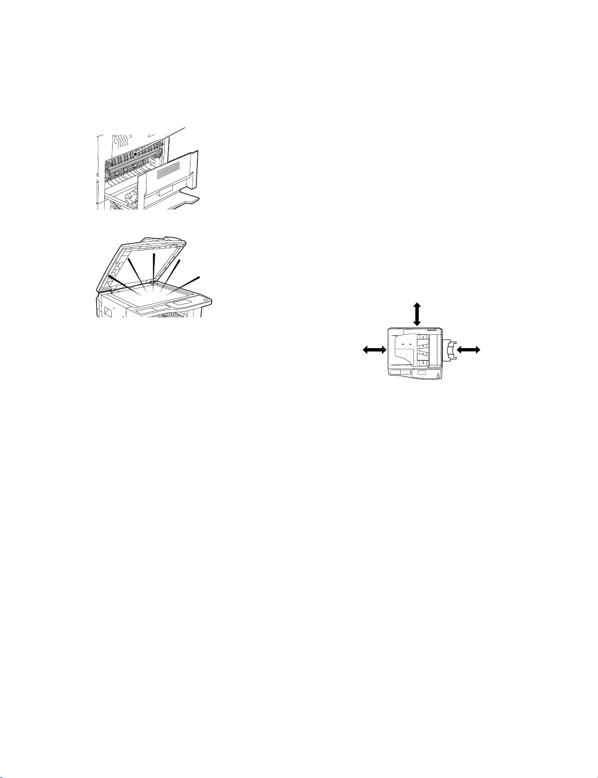
1. Cautions on using
A. Warning
•The fusing area is hot. Exercise care in this area when removing misfed
paper.
Fusing unit
•Do not look directly at the light source. Doing so may damage your eyes .
2. Installation requirements
Improper installation may damage this product. Please note the following
during initial installation and whenever the
machine is moved.
1. The machine should be installed near an accessible power outlet for
easy connection.
2. Be sure to connect the power cord only to a power outlet that meets
the specified voltage and current requirements. Also make certain the
outlet is properly grounded.
•For the power supply requirements, see the name plate on the back of
the main unit.
Note: Connect the machine to a power outlet which is not used for other
electric appliances. If a lighting fixture is connected to the same
outlet, the light may flicker.
3. Do not install your machine in areas that are:
•damp, humid, or very dusty
•exposed to direct sunlight
•poorly ventilated
• su bject to extreme temperature or humidity changes, e.g., near an air
conditioner or heater.
4. Be sure to allow the required space around the machine for servicing
and proper ventilation.
8" (20 cm)
B. Cautions
•Do not switch the machine rapidly on and off. After turning the machine
off, wait 10 to 15 seconds before turning it back on.
•Place the machine on a firm, level surface.
• When the machine is not used for a long time, for example, during
prolonged holidays, turn the power switch off and remove the power
cord from the outlet.
• When moving the machine, be sure to turn the power switch off and
remove the power cord from the outlet.
•Do not cover the machine with a dust cover, cloth or plastic film while
the power is on. Doing so may prevent heat dissipation, damaging the
machine.
•Do not make any modifications to this machine. Doing so may result in
personal injury or damage to the machine.
•Do not make copies of anything which is prohibited from copying by law.
The following items are normally prohibited from printing by national
law . Other items may be prohibited by local law.
Money, Stamps, Bonds, Stocks
Bank drafts, Checks, Passports, Driver’s licenses
•Do not touch the photoconductive drum. Scratches or smudges on the
drum will cause dirty prints.
•Store spare toner car tridges in a cool dry plac e without removing from
the package before use.
• If they are exposed to direct sunlight or excessive heat, poor copies
may result.
8"
(20 cm)
8"
(20 cm)
AR-M207 M165 M162 GENERAL 1-1
Page 5
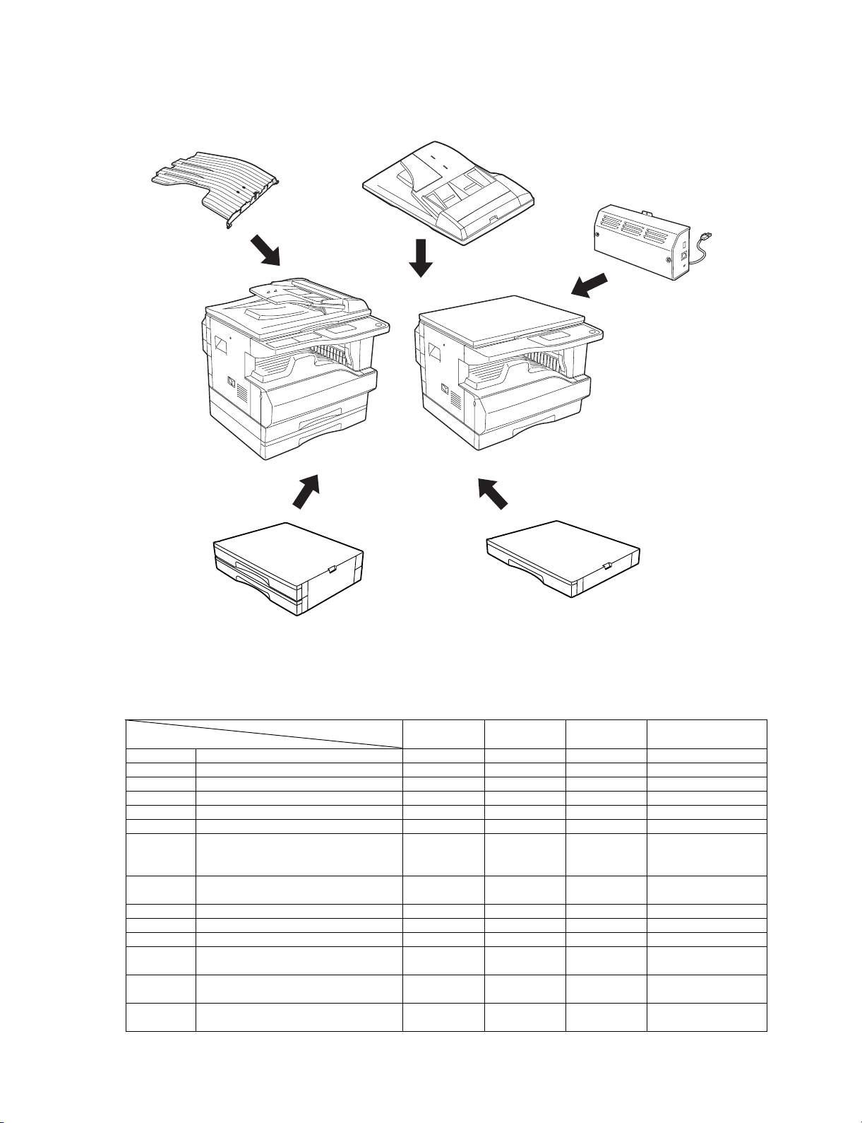
3. Configuration
A. System Configurations
Job separator
(AR-TR4)
RSPF(AR-RP6N)
SPF(AR-SP6N)
AR-M207
With the RSPF installed
Network Box
(AR-NB3)
AR-M165
AR-M162
2 X 250 sheet paper
feed unit
(AR-D25)
MODEL
OPTION
AR-RP6N REVERSING SINGLE PASS FEEDER OPT OPT NO
AR-SP6N SINGLE PASS FEEDER OPT OPT OPT
AR-VR5 DOCUMENT COVER OPT STD STD
AR-D24 250-SHEET PAPER FEED UNIT OPT OPT OPT
AR-D25 2 x 250-SHEET PAPE R FEED UNI T OPT OPT OPT
AR-TR4 JOB SEPARATOR TRAY KIT OPT OPT OPT
AR-EB9 DUAL FUNCTION BOARD STD*1 STD STD*1 *1
AR-NB3 NETWORK PRINTING / SCANNING
EXPANSION K I T
AR-FX11 FACSIMILE EXPANSION KIT OPT OPT OPT
AR-SM5 EXPANSION MEMORY OPT OPT OPT
AR-MM9 FAX EXPANSION MEMORY OPT OPT OPT
AR-PF1 BARCODE-FON T KI T OPT OPT OPT The AR-NB3 is
AR-PK1N PS3 KIT OPT OPT OPT The AR-NB3 is
AR-PF2 FLASH MEMORY KIT OPT OPT OPT The AR-NB3 is
AR-M207 AR-M165 AR-M162 Remark
OPT OPT OPT
250 sheet paper
feed unit
(AR-D24)
Option for
USA,CANADA.
required
required
required
AR-M207 M165 M162 GENERAL 1-2
Page 6
[2] SPECIFICATIONS
1. Basic Specification
A. Base Engine
(1) Type
AR-M207, AR-M162 / M165 Desk-top
(2) Engine speed
Paper size AR-M207 AR-M162 / M165
A4/8.5" x 11" 20ppm 16ppm
A4R/8.5" x 11"R 14/15ppm 12ppm
A5/5.5" x 8.5" 20ppm 16ppm
B5/16K 20ppm 16ppm
B5R/16KR 16/15ppm 14ppm
8.5" x 13" 12ppm 11ppm
B4/8.5" x 14 12ppm 10ppm
A3/11" x 17"/8K 11/10/11ppm 9/ 9/10ppm
(3) Print performance
AR-M207 AR-M162 / M165
GDI Print* 12ppm 12ppm
SPLC Print 20ppm(ROPM) 16ppm(ROPM)
* GDI print measurement c onditions: Host PC/CPU = 500 700MHz o r
above, Windows 98SE, Data = TestChart-B1.doc, USB1.1, when
supporting A4/Letter.
Measurement method: With setting to 11, from completion of the first
paper exit to completion of the 11th paper exit
(4) Copy speed(cpm)
AR-M207 AR-M162 / M165
Normal
A4/8.5"x11" 20 20 20 16 16 16
A4R/
8.5"x11"R
A5/5.5"x8.5" 20 20 20 16 16 16
B5/16K 20 20 20 16 16 16
B5R/16KR 16/15 16/15 16/15 14 14 14
8.5x13" 12 12 12 10 10 10
B4/8.5"x14 12 12 12 10 10 10
A3/11"x17"/8K11/10/1111/10/1111/10/119/9/10 9/9/10 9/9/10
14/15 14/15 14/15 12 12 12
Reducti on
Enlargement
Normal
Reduction
Enlargement
(6) Job Speed
AR-M207 AR-M162 / M165
S S 20 Sheets/min(100%) 16 Sheets/min(100%)
S D 9 Sheets/min(45%) D D 8 Sheets/min(40%) -
* S S(from No. 1 cassette): 10 sheets of A4/8.5" x 11" document, 5
copies
* S D(from No. 1 cassette): 10 sheets of A4/8.5" x 11" document, 5
copies
* D D(from No. 1 cassette): 10 sheets of A4/8.5" x 11" document(20
surfaces), 5 copies
(7) Continuous copying
Max. number of
multi copy
1-999copies(Can be changed to 1-99 in key
operator programs)
(8) Engine composition
Photoconductor
type
Photoconductor
drum dia.
Process cleaning Blade
Copy lamp Cold cathode fluorescent lamp(CCFL)
Developing system Dry 2-component magnetic brush development
Charging system Saw teeth charging
Transfer system (+)DC scorotro n
Separation system (-)DC scorotron
Fusing system Heat roller
Process speed 88mm/s
OPC(Organic Photo Conductor)
30mm
(9) Engine resolution
Resolution Reading: 600 x 300dpi1(600 x 600dpi selectable)
Gradation Reading: 256 gradation, Writing: 2 gradations
Writing: 600x600dpi
(10)Scanner section
Scanner(Document table)
(5) First copy time
First copy time 7.2sec or less
* Measurement conditions: When feeding paper of A4/8.5" x 11" from the
main unit tray, polygon rotation state
Main unit first
stage
Main unit second
stage
Option paper feed
first stage
Option paper feed
second stage
Manual tray 7.5sec or less
First copy time from the document feed unit
SPF 12sec or less
RSPF 12s ec or less
7.2sec or less
8.5sec or less
9.5sec or less
10.5sec or less
AR-M207 M165 M162 SPECIFICATIONS 2-1
Page 7
(11) Document table
Max. Document
size
Scan area 297 x 431mm
Document
reference position
Detection(Platen) Available
Detection size Automatic detection(supported by each unit for
OR guide display Left back corner
AB and inch can be switched to each other by Sim.
A3/11"x17"
Left back corner reference
inch/AB)
AB system: A3, B4, A4, A4R, A5,
Inch system: 11" x 17", 8.5" x 14",
(Print display)
Left side document
guide
Left side document
guide
Back side document
guide(Bookmark)
8.5" x 11", 8.5" x 11"R
Document reference
position “ ”
(From the back)
[Postal card] · [A6 ] · [B 6
] · [5-1/2] · [A5 ] · [B5 ] ·
[A4/A5 ] · [8-1/2] · [B4/B5
] · [11] · [A3/A 4 ]
(From the left)
[5-1/2] · [A5] · [B5] · [A4/
A5 ] · [8-1/2] · [B5 ] · [11]
· [A4 ] · [13] · [14] · [B4 ] ·
[A3 ] · [17]
B5(Vertical),
A4(Vertical), bookmark
at 8" - 1/2" position(From
the left)
(12) SPF/RSPF
Type SPF/RSPF Single/Duple x automatic
document feeder unit
Scan speed Single surface When copying: 20-sheet
Document
reference position
Document size AB system: A3-A5
Document weight 56 - 90g/m²(15 - 24lbs)
Document load
capacity
Inhibited kinds of
documents
Detection Avaiable
Detection size * Automatic detection(A kind of detection unit is used
Document tray
guide display
Center
Inch system: 11" x17" - 5.5" x 8.5"
when duplex: 56 - 90g/m²(15 - 24lbs)
40 sheets(30 sheets of 90g/m² loadable)(30 sheets
for B4/8.5" x 13" or above)40 sheets of 4mm
thickness or below loadable
Transparency film, Perforated sheets, photo,
catalogue
by switching the software destination.)
AB system: A3,B4,A4,A4R,B5,B5R,A5
Inch system: 11" x 17", 8.5" x 14", 8.5" x
Tray
center(Marked)
Document
guide(Marked)
model/20 sheets/min
16-sheet model/16 sheets/min
When FA X: 23 sheets/min
11", 8.5" x 11"R, 5.5" x 8.5"
Document insertion direction
“ ”document face-up set
command
(From the center)
A3/A4, 11", B4/B5, 8.5",
A4R/A5, B5R, A5R, 5.5"
(13) Operation panel
a. Display device
Type LCD display with backlight
System FSTN
Display dot
number
LCD drive display
area
LCD brightness
adjustment
Type 7 segment LED(x 3)
b. Key
Mode selection
area
Basic input section Start key/LED
LCD display
section
Panel language
support
c. Characters used in LCD
Kind ROM font
Dot 6(W)x 12(H)
119 x 73 dots
78.867 x 41.653 mm
Available
Copy mode key(mode LED)
Print mode key(mode LED/ONLINE LED/DATA
LED)
Scanner mode key(mode LED)
Fax mode key(mode LED/LINE LED/DATA LED)
Numeric keys
* AUDIT CLEAR key
# Read End key
Clear/Stop key
Interru p t key
All Clear key
Exposure key(Color mode/Program)
Paper ke y(Resolution/Program)
Zoom key(Address)
Auto% key(Format/Broadcast)
Duplex key(Duplex scan)
Sort(Documen t size)
Special function key
Fax status key
Arrows key
OK key
Back key
LINE STATUS indicator
(when the fax option is installed)
English(Factory setting)
For the languages other than English, the key
sheet is packed together with the machine or
manual kit. Attach it when installing.
(14) Controller board
CPU H8S2321(16bit 1-chip microprocessor,
Memory 16MB(Single surface model)
Interface
IEEE1284 Parallel 1 port
USB1.1 1 port
USB2.0 1 port(Standard/option area)
Ethernet 1 port(Network box)
19.6608MHz)
32MB(Duplex surface model)
(15) Paper feed section
Type 4-stage paper feed tray + multi manual paper feed
Paper feed system Front loading, paper feed from the top
AR-M207 M165 M162 SPECIFICATIONS 2-2
Page 8
Main unit tray
Size to be fed A3, B4, A4, A4R, B5, B5R, A5(No.1 tray only)
16K, 16KR, 8K,
11" x 17", 8.5" x 14", 8.5" x 13", 8.5" x 11",
8.5" x 11"R, 5.5" x 8.5"(No. 1 tray only)
Paper size setting Us er setting
Paper size setting A3, B4, A4, A4R, B5, B5R, A5,
11" x 17", 8.5" x 14", 8.5" x 13", 8.5" x 11",
8.5" x 11"R, 5.5" x 8.5"
(For A5/5.5" x 8.5", however, No. 1 cassette only)
Paper size setting
when shipping
Kind and weight of
applicable paper
Paper feed
capacity
Paper type Standard paper, Recyc led paper
Remaining
quantity detection
AB system: A4
Inch system: 8.5" x 11"
Standard paper 56 - 90g/m²
Standard paper
250 sheets(64g/m²)
Only empty detection available
(16) Manual paper feed section
Manual paper feed
form
Paper size A3 - A6,
Manual paper feed
guide display
Kind and weight of
applicable paper
Paper capacity Standard
Paper kind AB system: Standard paper/Recycled paper/
Paper size
detection
Paper empty
detection
Foldable manual paper feed tray
11" x 17" - 8.5" x 11"
A3/A4, B4/B5, A4R/A5, B5R, A5R, B6R, A6R
Standard paper
Thick paper(56 - 200g/m²)
Recycled paper, Envelope, Transparency film,
Labels
100 Sheets
paper
Envelope AB system: 10 Sheets
Other Single paper feed(Transparency film,
Transparency film/Labels/Postal card/Envelope/
Thick paper(-200g/m²)
Inch system: Standard paper/Recycled paper/
Transparency film/Labels/Postal card/Envelope/
Thick paper(-200g/m²)
None
Available
(Standard paper: 56 - 80g/m²)(Multi
paper feed: 56 -128g/m²)
Inch system: 5 Sheets
Labels, Postal card)
(17) Duplex
Standard 20-sheet m odel: Standard provision
Type Switchback system
Paper size A3, B4, A4, A4R, B5, B5R, A5,
Kind and weight of
applicable paper
16-sheet model: Not available
11" x 17", 8.5" x 14", 8.5" x 13", 8.5" x 11",
8.5" x 11"R
Standard paper: 56 - 90 g/m²/15 - 24lbs Bond
(18) Paper exit section
Paper exit
position/system
Paper exit section
capacity
Paper exit paper
size/kind
Paper exit paper
full detection
Face do wn
250 sheets
All feedable paper types and sizes
Upper stage: Available(Detected when the job
separator is installed)
Lower stage: None
*250 sheets of counted and detected.
(19) Exposure(Print density)
Density mode Auto/Text/Photo
NO. Of manual
adjustment
Toner save mode Available(Default OFF with the service simulation)
5 steps(Text/Photo)
(20) Void width
Void area Lead edge: 1 - 4mm, rear edge: 4mm or less,
both sides: 6mm
Image loss 4mm or less
* For void area/image loss, normal/single copy.
* For the first sheet of manual paper feed, the rear edge void is disable.
(21) Warm-up
Warm-up time 45sec or less
Pre heat Available
Jam recovery time 45sec or less
Left for 60 sec after door open.
Standard condition, polygon stop
(22) Copy magnification ratio
Fixed
magnification ratio
Zooming 25-400%(SPF/RSPF: 50-200%)
Independent
zooming
AB system: 25, 50, 70, 81, 86, 100, 115, 122, 141,
200, 400%
Inch system: 25, 50, 64, 77, 95, 100, 121, 129,
141, 200, 400%
Vertical/horizontal: 25-400%
(SPF/RSPF: 50-200%)
(23) Power source
Voltage 100V, 110V, 120V, 127V, 230V(200V), 240V
Frequency 50/60Hz
Power switch One power source
(24) Power consumption
Max. Power
consumption
Power
consumption in
operation
Power
consumption when
standby
* Must conform to energy saving laws, international standards, and
company regulations.
1200W
550W
10W
AR-M207 M165 M162 SPECIFICATIONS 2-3
Page 9
(25) Environment support
Support program International Energy-Star
Nordic swan
Canadian environment selection program
Blue angel
eco-label
Green purchase network
Green purchase law
Energy-saving law
Green products
(26) Noises
Noise level Must conform to SS, blue angel, Nordic swan.
(27) Ozone & dust
Regulated value Ozone: 0.02mg/m³ or less
Dust: 0.075mg/m³ or less
Styrene: 0.07mg/m³ or less
(28) External dimensions
1-stage cassette model(floor
surface - glass surface)
1-stage cassette model(floor
surface - OC)
1-stage cassette model(floor
surface - SPF)
2-stage cassette model(floor
surface - glass surface)
2-stage cassette model(floor
surface - OC)
2-stage cassette model(floor
surface - SPF)
3-stage cassette model(floor
surface - glass surface)
3-stage cassette model(floor
surface - OC)
3-stage cassette model(floor
surface - SPF)
4-stage cassette model(floor
surface - glass surface)
4-stage cassette model(floor
surface - OC)
4-stage cassette model(floor
surface - SPF)
590(W) x 595(D) x 435(H)
590(W) x 595(D) x 469(H)
590(W) x 595(D) x 568(H)
590(W) x 595(D) x 520(H)
590(W) x 595(D) x 554(H)
590(W) x 595(D) x 652(H)
590(W) x 595(D) x 605(H)
590(W) x 595(D) x 640(H)
590(W) x 595(D) x 738(H)
590(W) x 595(D) x 690(H)
590(W) x 595(D) x 725(H)
590(W) x 595(D) x 823(H)
(29) Occupying area
Main unit only
(excluding the handle)
Main unit(Multi manual feed open) 880(W ) x 595(D)
590(W) x 595(D)
(30) Weight
20-sheet model
(Electronic sort : Standard)
20-sheet model
(Electronic sort : Option)
16-sheet model
(Electronic sort/Duplex)
16-sheet model
(Electronic sort : Standard)
16-sheet model
(Electronic sort : Option)
34.2 (Kg)
33.8 (Kg)
30.6 (Kg)
30.0 (Kg)
29.7 (Kg)
(31) Printer basics
GDI/SPLC Print
Print speed GDI: 12PPM(GDI Print, USB2.0(Full speed), A4/
First Print 7.2sec or less
Resolution 600dpi
Duplex print Available
Paper feed system Paper feed tray and multi paper feed
Shifter Installed to the main unit paper exit section.
Supported OS Windows95/98/Me/NT4.0(Workstation SP5 or
Emulation GDI
Interface IEEE1284(ECP, Compatible)
PnP Support Windows 95/98/Me/2000/XP
Software Status Window
ROPM When the Dual function board (AR-EB9) is
WHQL Yes(XP/2000) after a few month later from first lot.
Letter)
Measurement conditions:
Host PC/CPU: 500 700MHz, RAM: 256MB or
above, Windows98SE
Data Testchart-B1, dot
SPLC: According to the main machine speed.
Shit amount: 1 inch(25.4mm)journalizing according
to every print j o b.
later)/2000(Professional)/XP(Home/Professional)
SPLC(JBIG-GDI): When the Dual function board
(AR-EB9) is installed (Standard or option).
USB1.1
USB2.0(When the Dual function board (AR-EB9)
is installed (Standard or option).
installed (Standard or option).
(32) Scanner basics
Type Flat bed color scanner
Scan system Document table/document feed unit
Light source Whit e CCFL
Resolution Basic 600 x 600 dpi
Document Sheet/Book
Effective scan
range
Scan speed 2.88msec /Line(C olor)
Input data 1bit or 12bit
Output data 1bit or 8bit
Scan color Black and white binary/Gray scale/Full color
Protocol TWAIN/WIA(XP Only)/STI
Interface USB1.1
Scanner utility Sharpdesk
Drop-out color Provided
Scanner button Destination selection by LCD
Duplex scan Available
Supported OS Windows98/Me/2000(Professional)/XP(Home/
Void area Lead edge/rear edge: 2.5mm
WHQL Yes(XP/2000) after a few month later from first lot.
Set range: 50 - 9600dpi
OC/SPF/RSPF: about 297(length)x 431(width)mm
USB2.0
Professional)
Side Left/right: 3.0mm
AR-M207 M165 M162 SPECIFICATIONS 2-4
Page 10
(33) Network box basics
Standard memory 64MB
Expansion
memory
Interface RJ45, USB port(for connection with the main unit)
LED Power LED, 10/100BASE-Tx mode LED,
Switch Status Switch
Supported OS
Setting software Internet Explorer 5.5 or later, Netscape Navigator 6
Expansion option PS expansion kit(AR-PK1N)
Network protocol TCP/ I P, IPX/SPX(NetWare), NetBEUI,
Emulation PCL/PS(PS is cancelled by the soft key.)
E-RIC Canceled by the soft key.
1DIMM 1 slot
144pin 128/256MB SO-DIMM
LAN status LED, USB status LED
Windows 95/98/Me/NT4.0(Workstation SP5 or
later)/2000 professional/XP Home Edition/XP
Professional Edition/Windows Sever 2003
Mac OS 8.6 - 9.2.2, 10.1.5, 10.2 - 10.2.8 (excluding
10.2.2), 10.3 - 10.3.4 (when PS option)
or later
Barcode font kit(AR-PF1)
Flash ROM kit(AR-PF2)
Sharpdesk(Shar p desk license kit AR-U seri es)
Ether Talk(Apple Talk)
ESC/P Font Kanji: Mincho, Gothic(Bitmap)
ANK: Roman, Sans Serif(Bitmap)
B. Peripheral devices basic specifications
(1) Single pass feeder(SPF)
Document set Face up
Document
reference position
Document
transport system
Document feed
direction
Document size AB system : A3 - A5
Document weight 56 - 90g/m²(15 - 24lbs)
Document set
quantity
External
dimensions
Weight 5.0kg
Power Supplied from the machine(Power consumption:
Document size
detection
Detection size AB system A3, B4, A4, A4R, B5, B5R, A5
Guide display (From the center)
Documents out of
specifications
Multi copy S-S, S-D(Duplex model)
Document mixture Not available
Random paper
feed
Document
reversion
Display
section(LED)
Right side center
Sheet through type
Document feed from the top
Inch system: 11" x 17" - 5.5" x 8.5"
40 sheets(40 sheets of 4mm thickness or less can
be loaded.)
(30 sheets of 90g/m² can be loaded. 30 sheets for
B4 or 8.5" x 13" or above.)
583 mm(W) x 435 mm(D) x 133 mm(H)
21W)
On the document feed trey
Inch system 11" x 17", 8.5" x 14", 8.5" x 11",
8.5" x 11"R, 5.5" x 8.5"
A3/A4, 11", B4/B5, 8.5", A4R/A5, B5R, A5R, 5.5"
Transparency film/Perforated document, photo,
catalogue
Not availabl e
Not availabl e
None
Reliability(MCBJ/
MCBF)
Document
replacement
speed(Standard
copy)
Item included Installation manual
Case color Frosty white
Installation Must be installed easily.
Conforms to the main unit.
S-S 16-sheet model: 100%
20-sheet model: 100%
S-D 20- sheet model: 45%(9 sheets/min)
D-D -
(2) Reversing single pass feeder(RSPF)
Document set Face up
Document
reference position
Document
transport system
Document feed
direction
Document size AB system: A3 - A5
Document weight 56 - 90g/m²(15 - 24lbs)
Document set
quantity
External
dimensions
Weight 5.4kg
Power Supplied from the machine(Power consumption:
Document size
detection
Detection size AB system A3, B4, A4, A4R, B5, B5R, A5
Guide display (From the center)
Documents out of
specifications
Multi copy S-S, S-D, D-D, D-S(Duplex model)
Document mixture Not available
Random paper
feed
Document
reversion
Display
section(LED)
Reliability(MCBJ/
MCBF)
Document
replacement
speed(Standard
copy)
Item included Installation manual
Case color Frosty white
Installation Must be installed easily
Right side center
Sheet through type
Document feed from the top
Inch system: 11" x 17" - 5.5"x8.5"
Duplex: 56 - 90g/m²(15 - 24lbs)
40 sheets(40 sheets of 4mm thickness or less can
be loaded.)
(30 sheets of 90g/m² can be loaded. 30 sheets for
B4 or 8.5" x 13" or above.)
583 mm(W) x 435 mm(D) x 133 mm(H)
26.4W)
On the document feed trey
Inch system 11" x 17", 8.5" x 14", 8.5" x 11",
8.5" x 11"R, 5.5" x 8.5"
A3/A4, 11", B4/B5, 8.5", A4R/A5, B5R, A5R, 5.5"
Transparency film, Perforated document, photo,
catalogue
Not availab le
Available(Not availab le for 5.5" x 8.5" and
5.5" x 8.5"R)
None
Conforms to the main unit
S-S 16-sheet model: 100%
20-sheet model: 100%
S-D 20- sheet model: 45%(9 sheets/min)
D-D 20-sheet model: 40%(8 sheets/min)
AR-M207 M165 M162 SPECIFICATIONS 2-5
Page 11
(3) 1-stage paper feed unit
Paper feed
capacity
Paper size
detection
Paper empty
detection
Paper size A3, B4, A4, A4R, B5, B5R, 11" x 17", 8.5" x 14",
Paper weight 56 - 90g/m²(15 - 24lbs)
Factory setting
size
Size selection A3, B4, A4, A4R, B5, B5R,11" x 17", 8.5" x 14",
Cassette
installation/
removal
Power Supplied from the machine(Power consumption:
External
dimensions
Weight 5.0Kg
Reliability(MCBJ/
MCBF)
Item included Installation manual, Paper size label
Case color Frosty white
250 Sheets
Not available(The paper size can be set with the
function menu.)
Available
8.5" x 13", 8.5" x 11", 8.5" x 11"R, 16K, 16KR, 8K
AB system: A4
Inch system: 8.5" x 11"
8.5" x 13", 8.5" x 11", 8.5" x 11"R
Can be made by the user
5.6W)
590 mm(W) x 471 mm(D) x 88mm(H)
Conforms to the main unit
(4) 2-stage paper feed unit
Paper feed
capacity
Paper size
detection
Paper empty
detection
Paper size A3, B4, A4, A4R, B5, B5R, 11" x 17", 8.5" x 14",
Paper weight 56 - 90g/m²(15 - 24lbs)
Factory setting
size
Size selection A3, B4, A4, A4R, B5, B5R
Cassette
installation/
removal
Power Supplied from the machine(Power consumption:
External
dimensions
Weight 10.0Kg
Reliability(MCBJ/
MCBF)
Item included Installation manual, Paper size label
Case color Frosty white
250 Sheets x 2
Not available(The paper size can be set with the
function menu.)
Available
8.5" x 13", 8.5" x 11", 8.5" x 11"R, 16K, 16KR, 8K
AB system: A4
Inch system: 8.5" x 11"
11" x 17", 8.5" x 14", 8.5" x 13", 8.5" x 11",
8.5" x 11"R
Can be made by the user
8.4W)
590 mm(W) x 471 mm(D) x 174 mm(H)
Conforms to the main unit
(5) Dual function board
Expansion
function
Electronic sort
compress function
Memory fo r
electronic sort
Electronic sort
scan quantity
Memory
expansion
Item included Installation manual,
Electronic sort function, 2In1/4In1, Rotation copy,
Edge erase/Center erase, Margin shift, Card shot
USB2.0(High-speed support),SPLC print(JBIGGDI), ROPM function
JBIG
16MB
A4 standard document(Test chart B)100 sheets
DIMM Memory slot x 1
Max. 256MB x 1slot + 16MB(Max 272MB in total)
(Externally described as max. 256MB x 1)
(6) Original cover(OC)
Function Up/down open/close mechanism
Item included Installation manual
(7) 256MB expansion memory
Memory 256MB
Item included Installation manual
(8) Job separator
Installation
conditions
Bin number 1 bin
Distribution
system
Paper size Conforms to the main unit paper feed paper.
Paper weight Conforms to the main unit paper feed paper.
Paper exit section
capacity
Paper exit job Upper stage: FAX output or printer output
Paper exit full
detection
Power None
Item included Installation manual
Case color Frosty white
Installation Must be installed easily
Install when the printer or the FA X is expanded.
Perf orms paper exit for every job
Controlled by the main unit.
Upper stage: 100 Sheets
Lower stage: 150 Sheets
Lower stage: Copy output or printer output
Upper stage: Available
Lower stage: YES (Full detection by the counter)
(9) Network box
Function Supports the network printer(PCL/PS)and the
Power Supplied from the machine
External
dimensions
Item included USB2. 0code x 1
network scanner.
(Power consumption: 5.5W)
248 mm(W) x 127 mm(D) x 59 mm(H)
Software CD(Driver/Network setting/application)
Installation manual
(10) Facsimile expansion kit
Function FAX expansion option
Item included One-touch dial key, destination label, installation
manual
(11) Barcode font kit
Same as the AR-PF1.
(12) Flash memory kit
Same as the AR-PF2.
(13) PS3 expansion kit
Same as the AR-PK1N.
(14) Facsimile expansion memory
Same as the AR-MM9.
AR-M207 M165 M162 SPECIFICATIONS 2-6
Page 12
C. Various functions specifications
(1) Copy function specification
Function/
Special function
Automatic paper
selection
Automatic
magnification
ration selection
Auto tray
switching
Memory copy Yes
Rotation copy Yes (When electronic sort)
Electronic sort Yes (Standard or option)
Rotation sort No
X Y zoom Yes
Dual page copy Yes (Enlargement invalid/SPF
Sort function Yes (Standard or option)
Margin shift Yes (When electronic sort)
Edge erase Yes (When electronic sort)
Center erase Yes (When electronic sort)
Black/white
reverse
2in1/4in1 Yes (When electronic sort)
Sorter Yes (Offset function)
Card shot Yes (When electronic sort)
Preheating Yes (Set by the key operator
Auto shut-off Yes (Set by the key operator
Total counter Yes
Duplex Yes (Standard provision for the
Toner save Yes (Set according to the
Department
management
Yes
Yes
Yes
invalid(Patent rotation)
100 sheets of A4 standard
document (Test Chart B)are sorted.
Default
AB system: 10mm(5, 10, 15,
20mm)
Inch system: 1/2 Inch(1/4, 1/2, 3/4,
1 Inch)
Default
AB system: 10mm(5, 10, 15,
20mm)Inch system: 1/2 Inch(1/4,
1/2, 3/4, 1 Inch)
Default
AB system: 10mm(5, 10, 15,
20mm)
Inch system: 1/2 Inch(1/4, 1/2, 3/4,
1 Inch)
No
program.)
program.)
model of 20-sheet model only)
destination) (No setting. * Default
OFF with the service simulation.)
Yes
(Copy/printer/scanner: 50 Dept,
Fax 50 dept)
(2) Printer function specification
a. GDI/SPLC Printer
<Summary>
Platform IBM PC/AT(Include compatible machine)
Supported OS IEEE1284 Windows95/98/Me/
USB1.1 Windows98/Me/
USB2.0 Windows2000(Professional)/
Emulation GDI/JBIG GDI
Memory Environments for full operations of the above OS
<GDI/SPLC Printer function>
Only the summary is described on this item.
Function Content
Main Copies 1-999 Makes prints of the set
Collate Collate
Document
Style
N-up *1 2/4 The set pages are printed
N-up Order Z
N-up Border Yes/No Border lines are printed
Duplex 1-sided
Paper Paper Size A3/B4/A4/B5/
Custom Paper
Size *2
Fit to Page Yes/No The print size is changed
Image
Orientation
Paper
Selection
Rotate 180
Degree
NT4.0(Workstation SP5)/
2000(Professional)/XP(Home/
Professional)
2000(Professional)/XP(Home/
Professional)
XP(Home/Professional)
number of copies.
Uncollate
1-sided
2-sided(Book)
2-sided(Tablet)
2-sided(Book)
2-sided(Tablet)
A5/A6/B6/
Ledger/Legal/
Foolscap/
Folio/Letter/
Invoice/
Executive/8K/
16K/COM-10/
DL/C5/
Custom/Postal
card
1 size Width: 100 - 297mm
Portrait
Landscape
Auto
Bypass
Tray 1/2(3/4)
Yes/No Data are rotated 180
When this item is set to
"Collate," prints of two or
more copies are collated.
When set to "Uncollated,"
two or more copies of each
page are
printed(uncollated).
Single face or double face
print is made according to
the setting. When set to
duplex, the printing
direction differs depending
on book or tablet.
on one sheet.
between pages printed on
one sheet.
Print is made in the set
paper size. Even when the
actual paper size differs
from the set paper size,
images are formed printed
in the set paper size.
Length: 148-431.8mm
according to the set
content.
Printing is made in the set
direction.
Paper is fed from the set
paper feed tray.
degrees and printed.
AR-M207 M165 M162 SPECIFICATIONS 2-7
Page 13
Function Content
Paper Output Tray
Selection
Advanced Print Quality Draft
Image
Adjustment
Brightness 0 - 100% The image brightness is
Contrast 0 - 100% T he image contrast is
Pured Black
print
Watermarks
Watermarks None/TOP
User Setting Add/Update/
Position Center
Size 6 - 300
Angle ± 90
Grayscale 0 - 255
Edit Font Yes
On First Page
only
Upper Tray
Center Tray
Normal
Photo
Yes/No Contrast and brightness of
Yes/No A docum ent ma de by a
SECRET/
CONFIDENTI
AL/DRAFT/
ORIGINAL/
COPY
Delete
X: ± 50
Y : ± 50
Yes /No
When the job separator is
installed, selection is made
between the upper stage
and the center stage of the
paper exit tray.
Draft/Normal (only for
Windows 9x, Me)
images are adjusted. For
Windows NT4.0/2000/XP,
enable only for the Photo
mode of Print Quality.
adjusted by moving the
scale from 0 to 100. The
illustration image on the
left upper corner of the
display is changed.
adjusted by moving the
scale from 0 to 100. The
illustration image on the
left upper corner of the
display is changed.
CAD program is printed in
black to provide clear print
of color line images and
texts.
(3) Scanner function Specification
a. PUSH Scan(USB)
Supported OS Win98/Me/2000/XP
Hardware
environment
Selectable
destination
b. PULL Scan(TWAIN)
Supported OS Win98/Me/2000/XP
Hardware
environment
Duplex scan Yes
Color mode Black and white(Simple binary)/Black and
Resolution Pull: 600 x 600dpi
Preview function Yes
Zoom preview
function
Rotation scan Yes (90 degrees/180 degrees/270 degrees)
Brightness/
contrast
adjustment
Gamma
adjustment
Color matching None/Printer/CRT/LCD display/ICM
Edge emphasis None/Normal/Strong/Blur
Black/white
reverse
Light source
selection
Threshold value
setting
Void area addition Available(Top/End edge = 2.5mm /Left/Right =
Set contents save Yes
(System)Must meet the operating conditions of
each OS.
(HDD)8MB or above: 100MB or above
recommendable
(Monitor)800 x 600 dots or above, 256 colors or
more must be displayed.
(Other)USB port(1.1 or 2.0)
SharpDesk/E-mail software/Fax software/OCR
software/MS Word
USB TW AIN
(System)Must meet the operating conditions of
each OS.
(HDD)8MB or above: 100MB or above
recommendable
(Monitor)800 x 600 dots or above, 256 colors or
more must be displayed.
(Other)USB port
white(Error diffusion)/Gray scale/Full color
Emulation: 50-9600dpi
Custom: 50-9600dpi
Yes
Auto/Manual(-100 - +100)
Yes
Yes
Yes (Red/Green/Blue/White)
Auto/Manual(1 - 254)
3.0mm)
c. Network Push scan(When the network box is installed)
Selectable
destination
Destination
selection method
AR-M207 M165 M162 SPECIFICATIONS 2-8
Scan to E-mail/FTP/Desktop
Address book
LDAP retrieval/selection
Ad-Hoc(10-key input)
Page 14
[3] CONSUMABLE PARTS
1. Supply system table
A. USA / CANADA
NO Name Content Life Product name Remark
1 Toner cartridge(Black)
<With IC>
2 Developer Developer
3 Dru m kit Drum
B. Europe / Australia / New Zealand
NO Name Content Life Product name Remark
1 Toner cartridge(Black)
<With IC>
2 Developer Developer
3 Dru m kit Drum
Toner
(Toner: Net Weight 537g)
Vinyl bag
(Developer : Net Weight 400g)
Drum fixing plate
Toner
(Toner: Net Weight 537g)
Vinyl bag
(Developer : Net Weight 400g)
Drum fixing plate
x10
160K AR-202MT Life setting by A4 6% document
x10
x10 500K AR-202MD
x1x150K AR-202DR
x10
160K AR-202LT Life setting by A4 6% document
x10
x10 500K AR-202LD
x1x150K AR-202DM
AR-M207 M165 M162 CONSUMABLE PARTS 3-1
Page 15
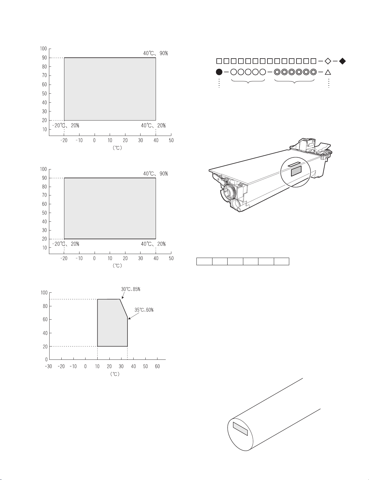
2. Environmental conditions
A. Transport conditions
(1) Transport conditions
3. Production number identification
<Toner cartridge>
The label on the toner cartridge shows the date of production.
Humidity (%)
Temperature
(2) Storage conditions
Humidity (%)
Temperature
Ver.No.Production
place
Serial
number
Year/
Month/
Day
<Drum cartridge>
The lot number, printed on the front side flange, is composed of 6 digits,
each digit showing the following content:
123456
B. Use conditions
Use environment
conditions
Humidity (%)
Temperature
C. Life(packed conditions)
Photoconductor drum (36 months from the production month)
Developer, toner (24 months from the production month)
1 Alphabet
Indicates the model conformity code. A for this model.
2 Number
Indicates the end digit of the production year.
3 Number or X, Y, Z
Indicates the month of packing.
X stands for October, Y November, and Z December.
4/5 Number
Indicates the day of the month of packing.
6 Alphabet
Indicates the production factory. "A" for Nara Plant, “C“ for
SOCC
AR-M207 M165 M162 CONSUMABLE PARTS 3-2
Page 16
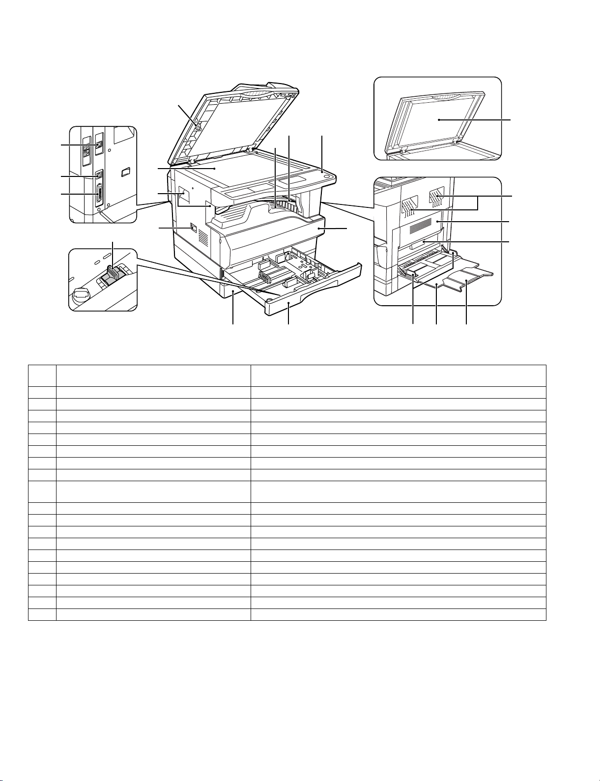
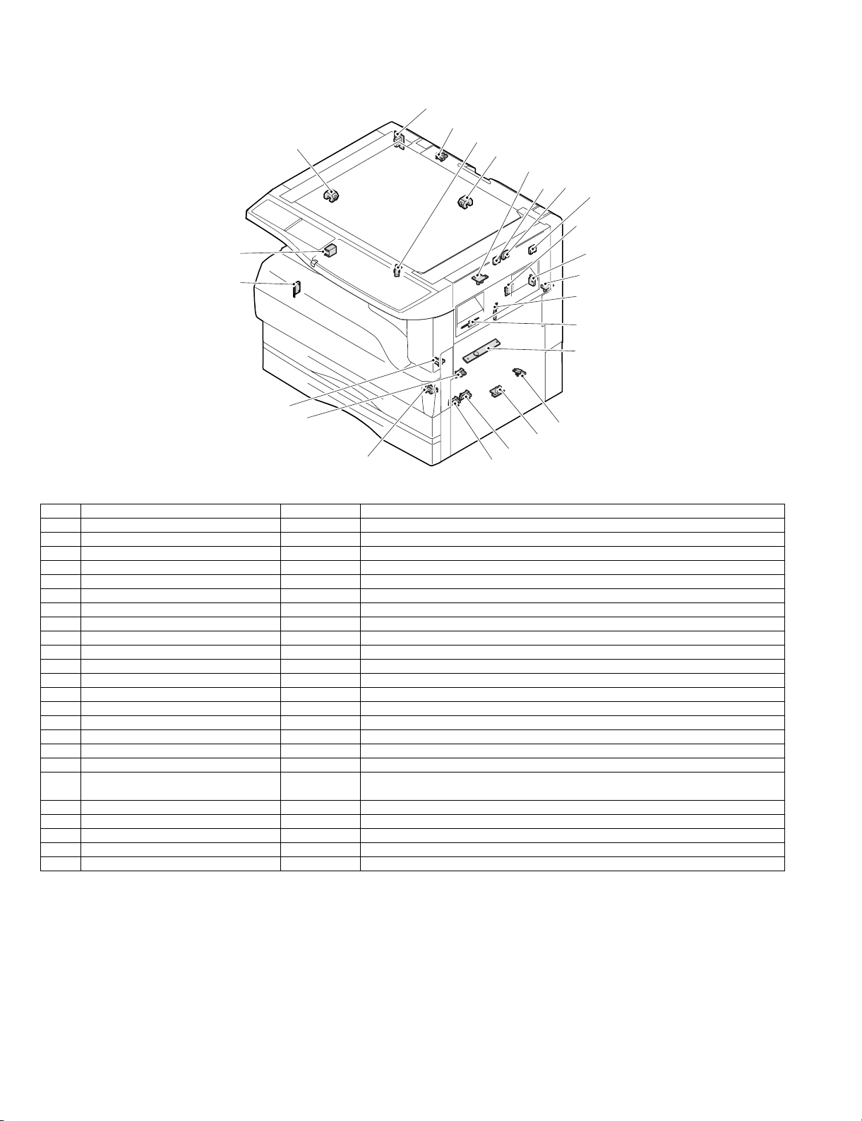
[4] EXTERNAL VIEWS AND INTERNAL STRUCTURES
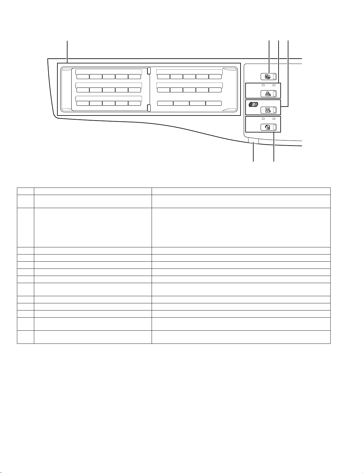
1. Appearance
5
10
1
9
11
15
2
3
4
1 USB 2.0 port (USB-2)
(when the dual function board is installed)
2 USB 1.1 port (USB-1) Connect to your computer to this port to use the printer and scanner functions.
3 Parallel port Connect to your computer to this port to use the printer function.
4 Charger cleaner Use to clean the transfer charger.
5 Glass cleaner Use to clean the original scanning glass.
6 Document glass Place an original that you wish to scan face down here.
7 Handles Use to move the machine.
8 Power switch Press to turn the machine power on and off.
9 Center tray Copies and printed pages are output to this tray.
10 Upper tray (when the job separator tray kit is installed) Received faxes (when the fax option is installed) and print jobs are deliv ered to this
11 Operation panel Contains operation keys and indicator lights.
12 Front cover Open to remove paper misfeeds or replace the toner cartridge.
13 Tray 1 Tray 1 can hold approximately 250 sheets of copy paper (64 g/m²).
14 Tray 2 Tray 2 can hold approximately 250 sheets of copy paper (64 g/m²).
15 Document cover (when installed) Open to make a copy from the document glass.
16 Side cover Open to remove misfed paper.
17 Side cover handle Pull to open the side cover.
18 Bypass tray guides Adjust to the width of the paper when using the bypass tray.
19 Bypass tray Special paper (heavy paper or transparency film) can be fed from the bypass tray.
20 Bypass tray extension Pull out when feeding large paper such as 11" x 17" and 8-1/2" x 14" (A3 and B4).
6
7
8
12
7
16
17
14 13
Connect to your computer to this port to use the printer and scanner functions.
tray.
18 19 20
AR-M207 M165 M162 EXTERNAL VIEWS AND INTERNAL STRUCTURES 4-1
Page 17
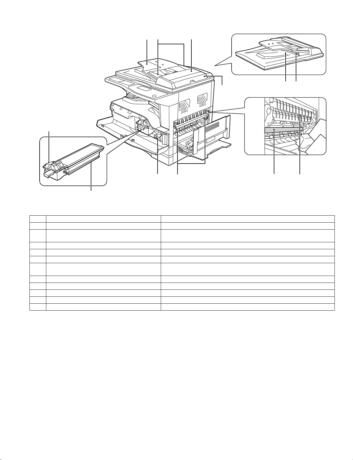
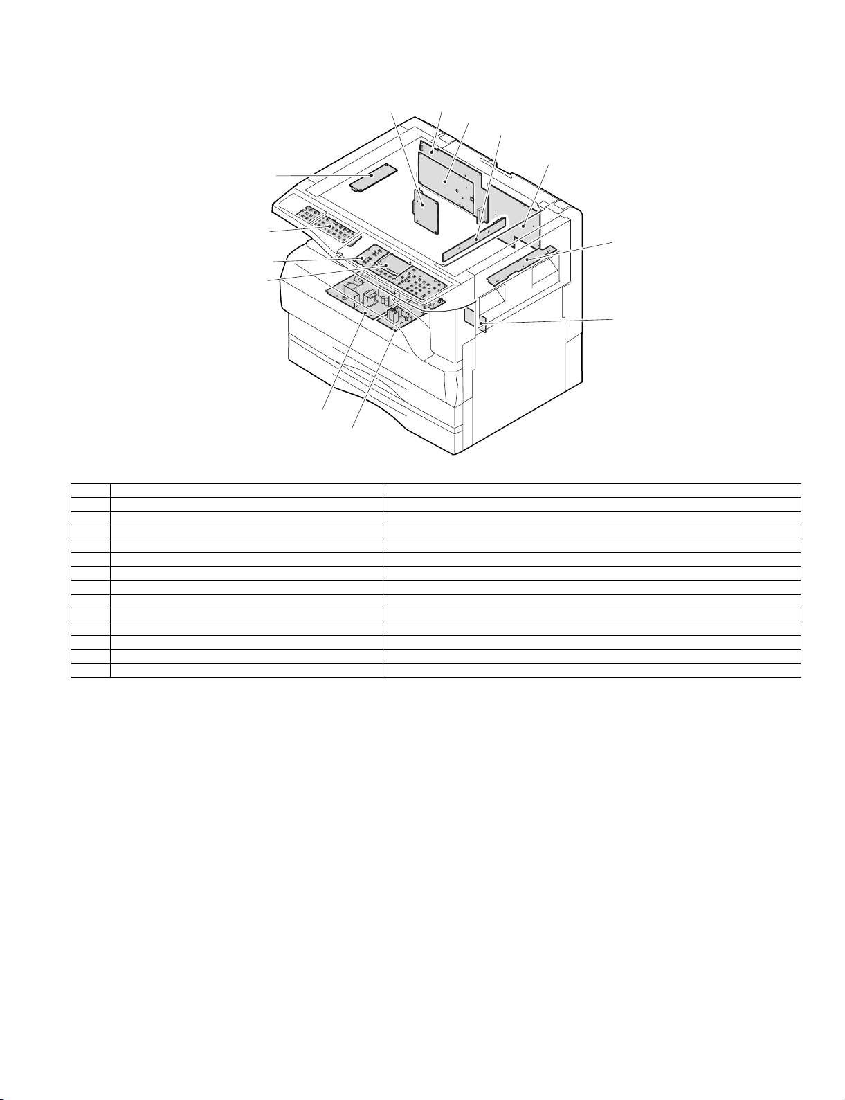
2. Internal
21
22
23 24
25
26
2728
29 30
31 32
21 T oner cartridge lock release lever To replace the toner cartridge, pull out the toner cartridge while pushing on this lever.
22 Toner cartridge Contains toner.
23 Document feeder tray (when the SPF is installed) Place the original(s) that you wish to scan face up here. Up to 40 sheets can be
24 Original guides (when the SPF is installed) Adjust to the size of the originals.
25 Feeding roller cover (when the SPF is installed) Open to remove misfed originals.
26 Right side cover (when the SPF is installed) Open to remove misfed originals.
27 Fusing unit release levers To remove the paper misfed in the fusing unit, push down on these levers and
28 Roller rotating knob Rotate to remove misfed paper.
29 Exit area (when the SPF is installed) Originals exit the machine here after copying/scanning when the SPF is used.
30 Reversing tray (when the RSPF is installed) Pull out to remove misfed originals.
31 Photoconductive drum Images are formed on the photoconductive drum.
32 Fusing unit paper guide Open to remove misfed paper.
Warning: The fusing unit is hot. Do not touch the fusing unit when removing misfed paper. Doing so may cause a burn or injury.
Caution: Do not touch the photoconductive drum (green portion) when rem oving the misfed paper. Doing so may damage the drum and cause
smudges on copies.
Note: The model name is on the front cover of the machine.
placed.
remove the paper.
AR-M207 M165 M162 EXTERNAL VIEWS AND INTERNAL STRUCTURES 4-2
Page 18
3. Operation panel
2134
26 27 28 29 30
ABCDE
31 32 33 34 35
FGH I J
36 37 38 39 40
KLMNO
41 42 43 44 45
PQR TS
46 47 48 49 50
U V W XYZ SP
SPEAKER
REDIAL/PAUSE SPEED
SHIFT
COMM. SETTING
SYMBOL
SPACE/
COPY
PRINT
SCAN
FAX
13
ON LINE
LINE
DATA
DATA
14
1 Keys for fax function (when the fax option is installed) These are used in fax mode.
2 [COPY] key/indicator Press to select copy mode. If pressed when "Ready to copy." appears or during
warm-up, the total number of sheets used appears while the key is pressed.
3 [PRINT] key/indicator Press to select print mode.
• ONLINE indicator
Print jobs can be received when this indicator is lit.
• DATA indicator
This lights steadily when there is a print job in memor y that has not been print ed,
and blinks during printing.
4 [SCAN] key/indicator Press to select scan mode.
5 Display Shows various messages. For more information see page 5-5.
6 [BACK] key Press to return the display to the previous screen.
7 [FAX STATUS] key This key is used in fax mode.
8 [OK] key Press to enter the selected setting.
9 Copy number display The selected number of copies appears. During copying, this shows the remaining
number of copies.
10 Numeric keys U se to select the number of copies.
11 [INTERRUPT] key/INTERRUPT indicator Interrupts a copy run to allow an interrupt copy job to be performed.
12 [C] key Press to clear the set number of copies or stop a copy run.
13 Information lamp
(when the fax option is installed)
14 [FAX] key/indicator (when the fax option is installed)
Information lamp blinks, when facsimile is received, or when the paper remains in
the tray.
This key is used in fax mode.
LINE indicator, DATA indicator
AR-M207 M165 M162 EXTERNAL VIEWS AND INTERNAL STRUCTURES 4-3
Page 19
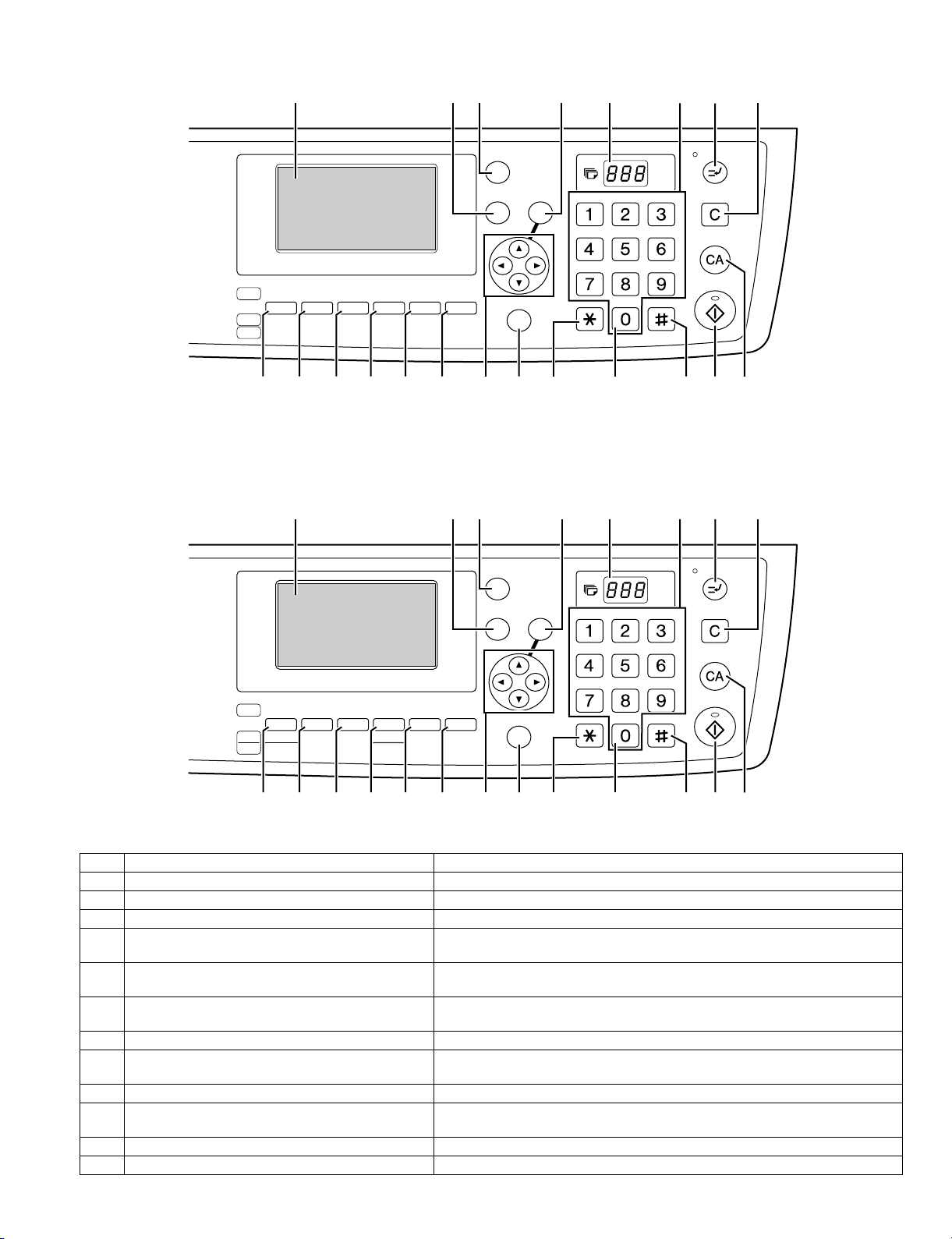
For U.S.A.
5967 8 1011 12
FAX STATUS
For other country
COPY
EXPOSURE
PAPER ZOOM
SCAN
COLOR MODE
RESOLUTION
FAX
PROGRAM
ADDRESS FORMAT
ADDRESS
RESOLUTION
BROADCAST
15 16 17 18 19
5967 8 1011 12
AUTO %
OUTPUT DUPLEX
ORIGINAL SIZE DUPLEX SCAN
ORIGINAL SIZE
20
BACK
DUPLEX SCAN
OK
SPECIAL FUNCTION
21 22 27262523 24
FAX STATUS
BACK
OK
ACC. #-C
ABC DEF
JKLGHI MNO
TUVPQRS WXYZ
@.-
READ-END
ABC DEF
_
JKLGHI MNO
TUVPQRS WXYZ
PAPER
COPY
SCAN
COLOUR MODE
FAX
EXPOSURE
PROGRAM
COPY
SELECT
RATIO
RESOLUTION
ADDRESS
BROADCAST
15 16 17 18 19
AUTO
IMAGE
FORMAT
2-SIDED
OUTPUT
COPY
SPECIAL FUNCTION
ORIGINAL SIZE DUPLEX SCAN
20
21 22 27262523 24
ACC. #-C
_
@.-
READ-END
15 [EXPOSURE] key Use to select the exposure mode. "AUTO", "TEXT", or "PHOTO" can be selected.
16 [PAPER] key (PAPER SELECT key) Use to manually select a paper tray.
17 [ZOOM] key (COPY RAT IO key) Press to select a reduction or enlargement copy ratio.
18 [AUTO%] key (AUTO IMAGE key) Press to have the copy ratio selected automatically.
19 [SORT] key (Only effective when the dual function
Use to select the sort function.
board is installed)
20 [DUPLEX] key (2-SIDED COPY key) (only on models
Select the two-sided copying mode.
that support two-sided printing)
21 Arrow keys Press to move the highlighting (which indicates that an item is selected) in the
display.
22 [SPECIAL FUNCTION] key Press to select special functions.
23 [ACC.#-C] key Press the end the use of an account and return the display to the account number
entry screen.
24 [0] key Press during a continuous copy run to display the number of copies completed.
25 [READ-END] key When copying in sort mode from the document glass, press this key when you have
finished scanning the original pages and are ready to start copying.
26 [START] key/indicator Copying is possible when this indicator is on. Press the key to start copying.
27 [CA] key Clears all selected settings and returns the machine to the default settings.
AR-M207 M165 M162 EXTERNAL VIEWS AND INTERNAL STRUCTURES 4-4
Page 20
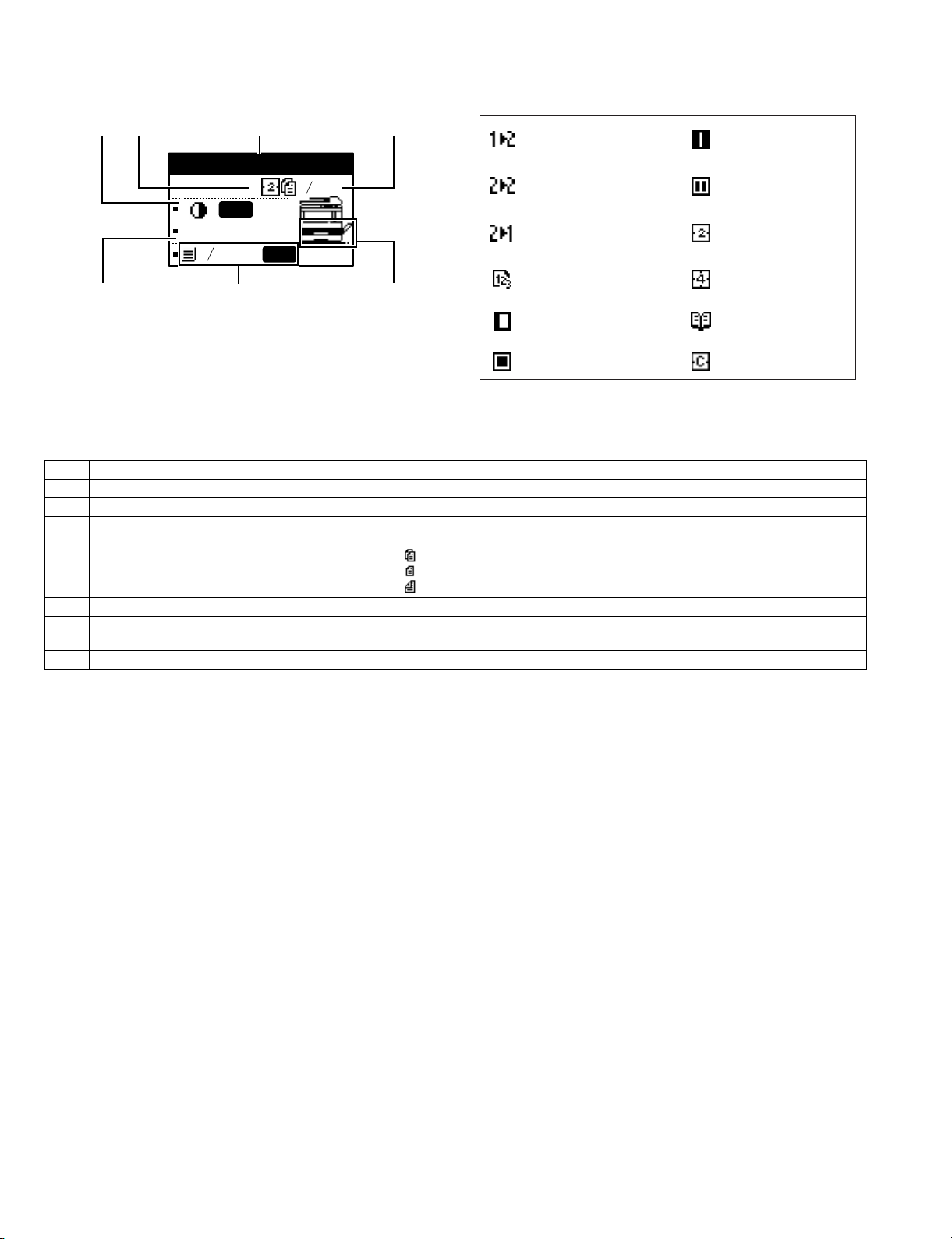
4. Display(base screen)
Example: Copy mode
23 4
1
Ready to copy.
AUTO
100%
1
2
8 x11
8 x11
AUTO
1
2
Icons appearing in the special function icon display
1-sided to 2-sided
copy
2-sided to 2-sided
copy
2-sided to 1-sided
copy
Center erase
copy*
Edge + Center
erase*
2 in 1 copy*
Sort function* 4 in 1 copy*
5
76
Margin shift copy* Dual page copy
* The display shown is the AR-M207 (when the optional
RSPF is installed) display.
* These only appear when the dual function board is
1 Exposure display Indicates the selected exposure mode.
2 Special function icon display Icons of enabled special functions will appear.
3 Message display Messages are displayed regarding machine status and operation.
4 Original size display The size of the placed original and the icon of the original scanning mode will
appear.
: One-sided scanning in the SPF.
: Scanning on the document glass
: Two-sided scanning in the RSPF.
5 Copy ratio display Displays the copy ratio for reduction or enlargement.
6 Paper size display Displays the selected paper size. When "AUTO" appears, the most suitable size of
paper is automatically selected.
7 Paper tray display The selected paper tray is highlighted.
Erase copy* Card shot*
installed.
AR-M207 M165 M162 EXTERNAL VIEWS AND INTERNAL STRUCTURES 4-5
Page 21
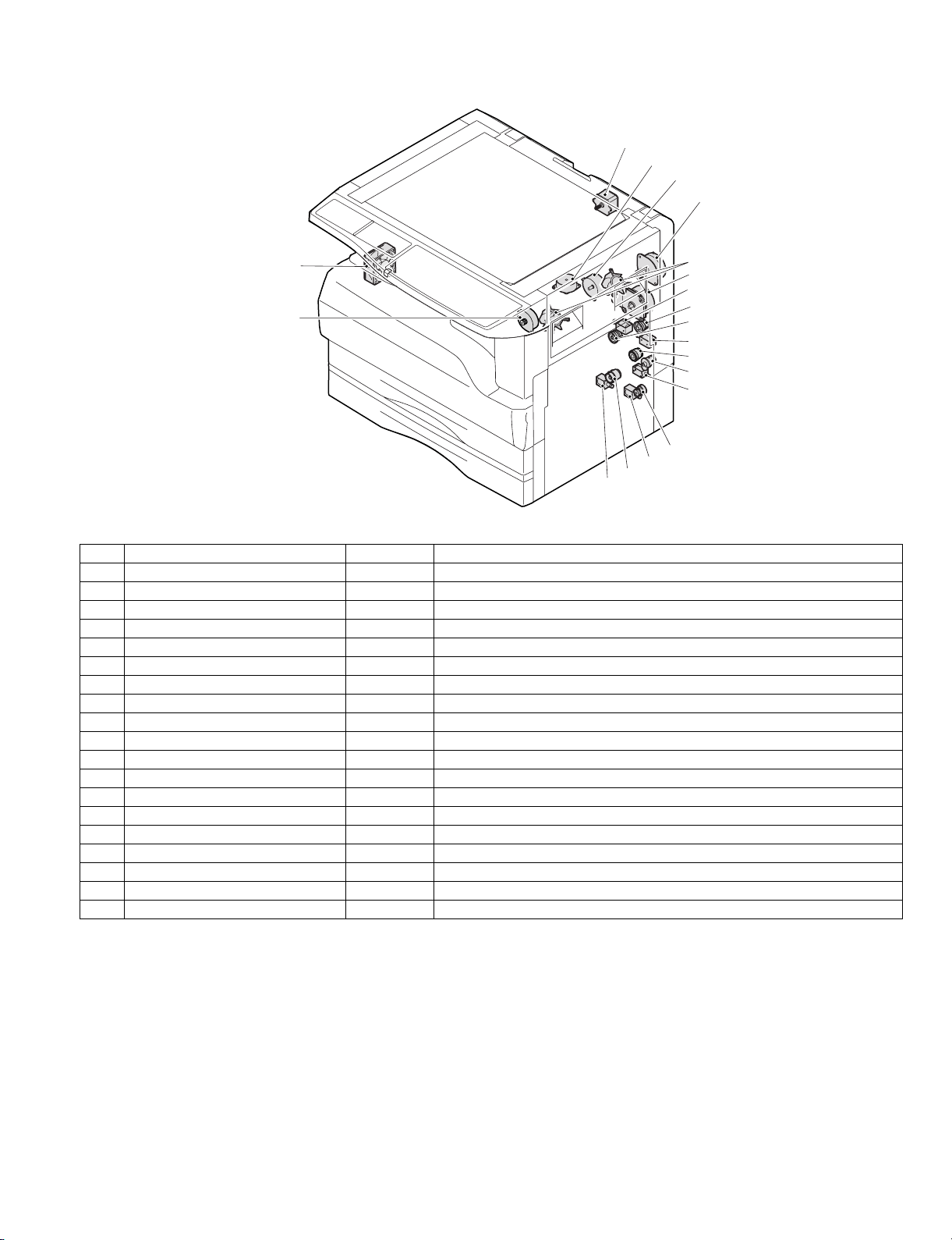
5. Motor, solenoid, clutch
1
2
3
4
18
5
6
7
19
8
9
10
11
12
13
14
15
16
17
No.
1 Mirror motor MRM Drives the optical mirror base (scanner unit).
2 Shifter motor SHTM Shifts the paper exit tray.
3 Toner motor TM Toner supply
4 Duplex motor DPX Switchback operation and paper exit motor in duplex.
5 Cooling fan motor CFM Cools the inside of the machine.
6 Main motor MM D r ives the machine.
7 1st tray paper feed clutch CPFC1 Drive the pick up roller
8 PS clutch RRC Drives the resist roller
9 Paper feed solenoid CPSOL1 Solenoid for paper feed from cassette
10 Resist roller solenoid RRS Resist roller rotation control solenoid
11 Manual paper transport clutch MPTC Drives the manual paper transport roller.
12 Manual paper feed clutch MPFC Drives the manual paper feed roller.
13 Manual paper feed solenoid MPFS Manual paper feed solenoid
14 2nd tray transport clutch CPFC2 Dr i ves the 2nd tray transport roller.
15 2nd tray transport solenoid FSOL1 2nd tray transport solenoid
16 2nd tray paper feed clutch CPFC 1 Drives the 2nd tray paper feed roller.
17 2nd tray paper feed solenoid PSOL2 2nd tray transport solenoid
18 Exhaust fan motor VFM Cools the inside of the machine.
19 Job separator motor Job separator tray up/down
Name
Code
Function operation
AR-M207 M165 M162 EXTERNAL VIEWS AND INTERNAL STRUCTURES 4-6
Page 22
6. Sensor, switch
23
1
22
2
24
3
19
18
20
4
17
16
21
5
6
7
8
15
14
9
10
13
No. Name Code Function operation
1 Mirror home position sensor MHPS Detects the mirror (scanner unit) home position.
2 Side door switch DSWR Side door open detection
3 Paper exit sensor (paper exit side) POD1 Detects paper exit.
4 Shifter home position sensor SFTHP Shifter home position detection
5 Paper exit sensor (DUP side) PDPX Paper transport detection
6 Thermistor RTH Fusing section temperature detection
7 Thermostat Fusing section abnormally high temperature detection
8 Toner density sensor TCS Toner quantity detection
9 2nd tray detection switch 2nd tray detection
10 Manual sensor MPED Manual transport detection
11 2nd tray door open/close sensor DRS2 2nd tray door open/close detection
12 2nd tray door paper pass sensor PPD2 2nd tray paper entry detection
13 2nd tray paper empty sensor CSS2 2 nd tray paper empty detection
14 Paper in sensor PIN Paper transport detection
15 Cassette empty Tray paper entry detection
16 Front cover SW Front cover open detection
17 Power switch MAIN SW Turns ON/OFF the main power source.
18 Tray full sensor TRAY-D Tray full detection
19 Job separator paper presence/empty
sensor
20 Job separator HP sensor LFT UP Job separator HP detection
21 Lower limit switch / JOBS_DLD Job separator tray lower limit position detection
22 OC sensor OCSW Original cover and SPF open/close detection
23 Original size sensor(Main Scaning) DSIN0 Original size detection
24 Original size sensor(Sub Scaning) DSIN1 Original size detection
TRAY-FULL Job separator tray paper presence/empty detection
11
12
AR-M207 M165 M162 EXTERNAL VIEWS AND INTERNAL STRUCTURES 4-7
Page 23
7. PWB unit
2
13
6
3
4
1
12
5
10
11
7
9
8
No. Name Function operation
1 Copy lamp Inverter PWB Copy lamp control
2 I / F PWB USB1.1, IEEE1284 I/F
3 CCD sensor PWB Image scanning
4 Main control PWB Main control PWB
5 Tray PWB Shifter motor control
6 IMC2 PWB Electronic sort, USB2.0 << Option:AR -EB 9>>
7 2nd cassette PWB 2nd cassette control
8 High voltage PWB High voltage control
9 Power PWB AC power input/DC power control
10 Operation main PWB Operation panel input/Display, operation panel section control
11 LCD OPE PWB Display and operation panel control
12 FAX • KEY PWB FAX operation input, key operation input<< Option:AR-FX11>>
13 FAX main PWB F AX control<< Option:AR-FX11>>
AR-M207 M165 M162 EXTERNAL VIEWS AND INTERNAL STRUCTURES 4-8
Page 24
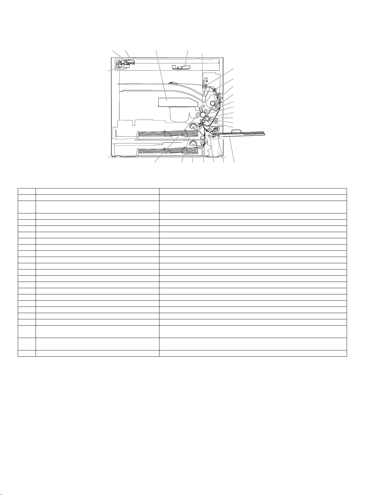
8. Cross sectional view
4
5
6
18
2
1
3
7
8
9
10
11
12
13
14
15
23
No. Name Function/Operation
1 Copy lamp Image radiation lamp
2 Copy lamp unit Operates in synchronization with No. 2/3 mirror unit to radiate documents
3 LSU unit Converts image signals into laser beams to write on the drum.
4 Lens unit Reads images with the lens and the CCD.
5 MC holder unit Supplies negative charges evenly on the drum.
6 Paper exit roller Used to discharge paper.
7 Transport roller Used to transport paper.
8 Upper heat roller Fuses toner on paper (with the Teflon roller).
9 Lower heat roller Fuses toner on paper (with the silicon rubber roller).
10 Waste toner transport roller Transports waste toner to the waste toner box.
11 Drum unit Forms images.
12 Transfer charger unit Transfer images (on the drum) onto paper.
13 DUP follower roller
14 Duplex transport roller Transports paper for duplex .
15 Resist roller Takes synchronization between the paper lead edge and the image lead edge.
16 Manual paper feed tray Manual paper feed tray
17 Manual paper pick up roller Picks up paper in manual paper feed.
18 No. 2/3 mirror unit Reflects the images from the copy lamp unit to the lens unit.
19 Manual transport roller Transports paper from the manual paper feed port.
20 2nd tray paper transport roller Transports paper from the 2nd tray.
21 2nd tray paper pick up roller
(semi-circular roller)
22 1st tray paper feed roller
(semi-circular roller)
23 MG roller Puts toner on the OPC drum.
22
21
20
19
17
sequentially.
Picks up paper from the 2nd tray.
Picks up paper from the 1st tray.
16
AR-M207 M165 M162 EXTERNAL VIEWS AND INTERNAL STRUCTURES 4-9
Page 25
[5] UNPACKING AND INSTALLATION
1. Installing conditions
A. Copier installation
Do not install your copier in areas that are:
•damp, humid, or very dusty
•exposed to direct sunlight
•poorly ventilated
•subject to extreme temperature or humidity changes, e.g., near an air
conditioner or heater.
•Be sure to allow the required space around the machine for servicing
and proper ventilation.
B. Power source
•Use an exclusive-use power outlet. If the power plug of this machine is
inserted into a power outlet commonly used with other illumination
units, flickers of the lamp may be result. Use a power outlet which is not
used commonly with any illumination units.
•Avoid complex wiring.
C. Grounding wire connection.
•To avoid danger, be sure to connect a grounding wire. If no grounding
wire is connected and a leakage occurs, a fire or an electric shock may
be result.
2) Open the front cover.
•Hold the both sides and pull down to open.
3) Loosen the screw and remove the developer cartridge.
4) Remove the developer tank from the developer cartridge.
2. Removal of protective material and fixing
screw
1) Remove all tapes and protective material.
• Remove all tapes, then open the document cover and remove the
protective material of sheet shape
2) Remove the fixing screw.
•Use a coin to remove the fixing screw.
•The fixing screw is required when transporting the machine. Keep it in
the tray. (Refer to the later description.)
3.Installing procedure
A.Developer cartridge installation
1) Open the manual tray, and open the side cover.
5) Supply developer into the developer tank while rotating the MG roller
in the arrow direction.
MG roller
* Shake the developer bag enough before opening it.
Hook
Note: Check that the DV seal is free from developing agent. If developing
agent is attached to the DV seal, clean it carefully.
Check to insure that the hook is engaged in two positions.
6) Attach the developer tank to the developer cartridge.
* After supplying developer into the developer cartridge, do not tilt or
shake the developer cartridge.
7) Attach the developer cartridge to the copier, and fix it with the screw.
AR-M207 M165 M162 UNPACKING AND INSTALLATION 5-1
Page 26
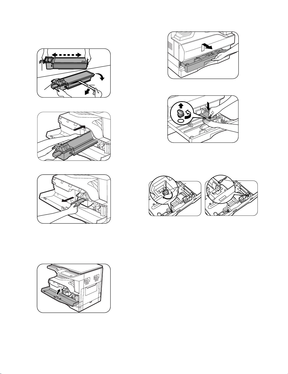
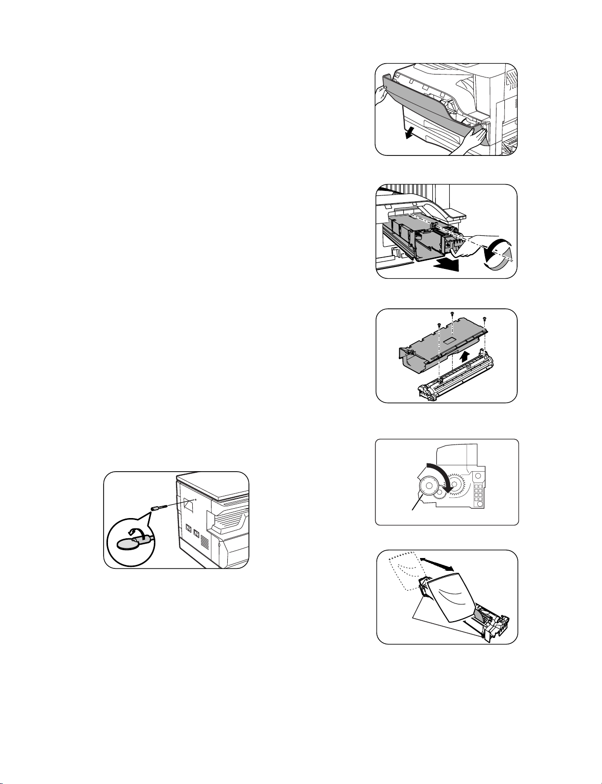
B. Toner cartridge installation
1) Shake the toner cartr idge several times horizontally, and rem ove the
tape.
* Do not hold the shutter lever when shaking.
* After removing the tape, do not tilt or shake the toner cartridge.
4 or 5 times
Shutter
4. Removal and storage of fixing screw
1) Lift the knob and gently pull out the tray .
Handle
2) Attach the toner cartr idge to the copier.
3) Pull the shutter lever.
Tape
2) Hold the paper pressure plate and turn t he fixing screw in the arrow
direction.
3) Store the fixing pin and the fixing screw in the tray.
•Store the fixing screw which was removed in the abov e procedure 2 and
the fixing screw which was removed in procedure 2 of 2.
•Removal of protective material and fixing screw in the storage place in
the tray.
Pressure
plate
lock
Screw
Close the front cover A, then close the side cover B.
•When closing the front cover, gently press the both sides.
•When closing the side cover, hold the knob.
• When closing the covers, be sure to close the front cover first, then
close the side cover. If closed in a wrong sequence, the covers may be
broken.
AR-M207 M165 M162 UNPACKING AND INSTALLATION 5-2
Page 27

5. Changing the paper size setting of a tray
DUPLEX
SPECIAL FUNCTION
ACC.
DUPLEX SCAN
DUPLEX SCAN
GH
PQR
DUPLEX
SPECIAL FUNCTION
GHI
OK
BACK
If the size of the loaded paper is different from the size shown in the
display, follow the steps below to change the paper size setting of the
tray.
The paper size setting cannot be changed during copying, printing, fax
printing (when the fax option is installed), or interrupt copying, or when a
misfeed has occurred. However, if the machine is out of paper or out of
toner, the paper size setting can be changed during copying, printing,
and fax printing.
The paper size cannot be set for the bypass tray.
4) Press the [ ] or [ ] key to select the paper tray for which the
paper size is being changed.
Example: Tray 2
PAPER SIZE SET
1
2
8 x11 11x17
11x17 8 x14
8 x11
8 x11R
1
2
1
2
1
2
1) Press the [SPECI AL FU NCTION] key.
SPECIAL FUNCTION
SPECIAL MODES
ORIG. SIZE ENTER
PAPER SIZE SET
The special function
screen will appear.
The screen shown above is the copy mode screen.
2) Press the [ ] or [ ] key to select "PAPE R SI ZE SET ".
DISPLAY CONTRAST
SPECIAL FUNCTION
SPECIAL MODES
ORIG. SIZE ENTER
PAPER SIZE SET
DISPLAY CONTRAST
3) Press the [OK] key.
PAPER SIZE SET
1
8 x11R 11x17
2
11x17 8 x14
8 x11
The paper size setting
screen will appear.
8 x11R
5) Press the [ ] key.
PAPER SIZE SET
1
2
8 x11 11x17
11x17 8 x14
8 x11
8 x11R
The cursor moves to the paper size selection position on the right.
6) Press the [ ] or [ ] key to select the paper size.
1
2
1
2
1
2
Example:
Selecting 8-1/2" x 14" size
PAPER SIZE SET
1
2
8 x11 11x17
11x17 8 x14
8 x11
8 x11R
To change the size of another paper tray, press the [ ] key and then
repeat steps 4 to 6.
7) Press the [OK] key.
1
2
1
2
1
2
A message asking you to confirm the new paper size setting will
appear.
8) Press the [OK] key.
The selected paper size will be stored and the display will return to
the base screen.
1
2
1
2
1
2
Note
: Shows tray "1".
: Shows tray "2".
Note
Affix the paper size label for the paper size selected in step 6 to the label
position on the right end of the tray.
AR-M207 M165 M162 UNPACKING AND INSTALLATION 5-3
Page 28
[6] ADJUSTMENTS
1. Adjustment item list
Section Adjustment item Adjustment procedure/SIM No.
A Process
section
B Mechanism
section
C Image density
adjustment
2. Copier adjustment
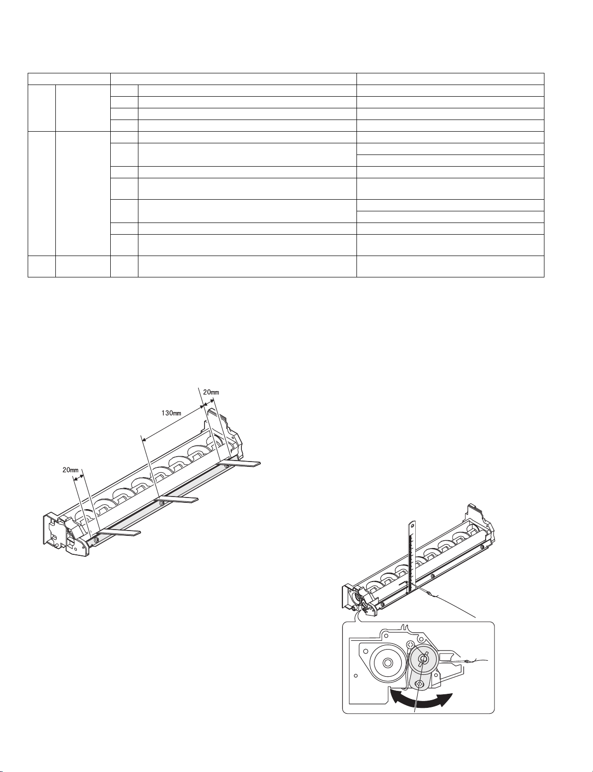
A.Process section
(1) Developing doctor gap adjustment
1) Loosen the developing doctor fixing screw A.
2) Insert a thickness gauge of 1.5mm to the three positions at 20mm
and 130mm from the both ends of the developing doctor as shown.
(1) Developing doctor gap adjustment Developing doctor gap adjustment
(2) MG roller main pole position adjustment MG roller main pole position adjustment
(3) Developing bias v oltage check
(4) Main charger voltage check
(1) Image position adjustment SIM 50
(2) Main scanning direction(FR direction) distortion balance
adjustment
No. 2/3 mirror base unit installing position adjustment
Copy lamp unit installing position adjustment
(3) Main scanning direction (FR direction) distortion adjustment Rail height adjustment
(4) Main scanning direction (FR direction) magnification ratio
SIM 48-1
adjustment
(5) Sub scanning direction (scanning direction) magnification ratio
adjustment
OC mode in copying (SIM 48-1)
SPF mode in copying (SIM 48-5)
(6) Off center adjustment OC mode (SIM 50-12)
(7) SPF white correction pixel position adjustment
SIM 63-7
(required in an SPF model when replacing the lens unit)
(1) Copy mode SIM 46-1
(2) MG roller main pole position adjustment
1) Remove and separate the waste toner box and put the developing
unit on a flat surface.
2) Tie a string to a needle or a pin.
3) Hold the string and bring the needle close to the MG roller
horizontally. (Do not use paper clip, which is too heavy to make a
correct adjustment.) (Put the developing unit horizontally for this
adjustment.)
4) Do not bring the needle into contact with the MG roller, but bring it to
a position 2 or 3mm apar t from the MG roller. Mark the point on the
MG roller which is on the extension line from the needle tip.
5) Measure the distance from the marking position to the top of the
doctor plate of the developing unit to insure that it is 18mm.
If the distance is not within the specified range, loosen the fixing
screw A of the main pole adjustment plate, and move the adjustment
plate in the arrow direction to adjust.
3) Push the developing doctor in the arrow direction, and tighten the
developing doctor fixing screw. (Perform the same procedure for the
front and the rear frames.)
4) Check the clearance of the developing doctor. If it is within the
specified range, then fix the doctor fixing screw with screw lock.
* When inserting a thickness gauge, be careful not to scratch the
developing doctor and the MG roller.
<Adjustment specification>
Developing doctor gap
Both ends (20mm from the both ends) :
C (Center) (150mm from the both ends) :
+0.1
1.5 mm
- 0.15
+0.15
1.55 mm
- 0.2
AR-M207 M165 M162 ADJUSTMENT 6-1
Page 29
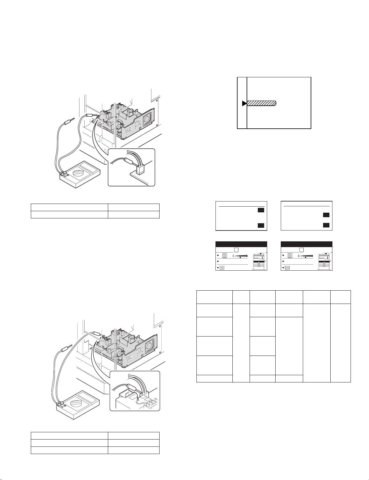
(3)Developing bias voltage check
Note: Use a digital multi-meter with an internal resistance of 10MΩ or
more.
1) Set the digital multi-meter range to DC700V.
2) Put the test rod of the digital multi-meter on the developing bias
voltage output check pin.
3) Turn on the power, execute SIM25-1.
<Specification>
Mode Specification
Developing bias volt age DC - 400±8V
(4) Grid bias voltage check
Note: Use a digital multi-meter with an internal resistance of 10MΩ or
more.
B. Mechanism section
(1) Image position adjustment
a. OC image lead edge position adjustment (SIM 50-1)
Note: In advance to this adjustment, the sub scanning magnification ratio
adjustment must be performed.
1) Set a scale on the OC table as shown below.
2) Make a copy.
3) Check the copy output. If necessary, perform the following
adjustment procedures.
4) Execute SIM 50-01.
Select a desired mode with the arrow keys, enter the adjustment
value with 10-key, and press [OK] key.
When [START] key is pressed, a sheet is printed.
When [RETURN] key is pressed, the process returns to the mode
selection window.
(Mode selection window 1)
Sim50-1 LEAD EDGE
1:TRAY1
2:TRAY2
3:MFT
1/2 [ 1- 99]
(Copy start window)
Ready to copy.
S
50
50
50
50
(Mode selection window 2)
Sim50-1 LEAD EDGE
4:DEN-A
5:RRC-A
6:DEN-B
2/2 [ 1- 99]
(Copy execution window)
Copies in progress.
S
50
1
50
50
1) Set the digital multi-meter range to DC700V.
2) Put the test rod of the digital multi-meter on the grid bias voltage
output check pin.
3) Turn on the power.
(The voltage is outputted in the grid bias High output mode during
warming up, and in the grid bias Low output mode when warming up
is completed.)
<Specification>
Mode Specification
Grid bias LOW DC - 380±8V
Grid bias HIGH DC - 525±10V
100%
8 1/2X11
100%
8 1/2X11
<Adjustment specification>
Adjustment
mode
OC image lead
edge position
Main cassette
SIM Display
text array
SIM
RRC-A R/0.1 Lead edge
50-1
TRAY1 H/0.1
Set
value
Spec
value
void:
1 - 4mm
Set
range
1 - 99
print start
position
2nd cassette
print start
TRAY2
Image loss:
3mm or
less
position
Multi bypass
MFT
tray print start
position
Lead edge void DEN-A B/0.05
5) Set the OC lead edge position set value (RRC-A) to [1]
The OC image scanning start position is shifted inside the document
edge.
6) Set the main cassette lead edge void adjustment value (DEN-A)* to [1]
The lead edge void becomes the minimum.
AR-M207 M165 M162 ADJUSTMENT 6-2
Page 30
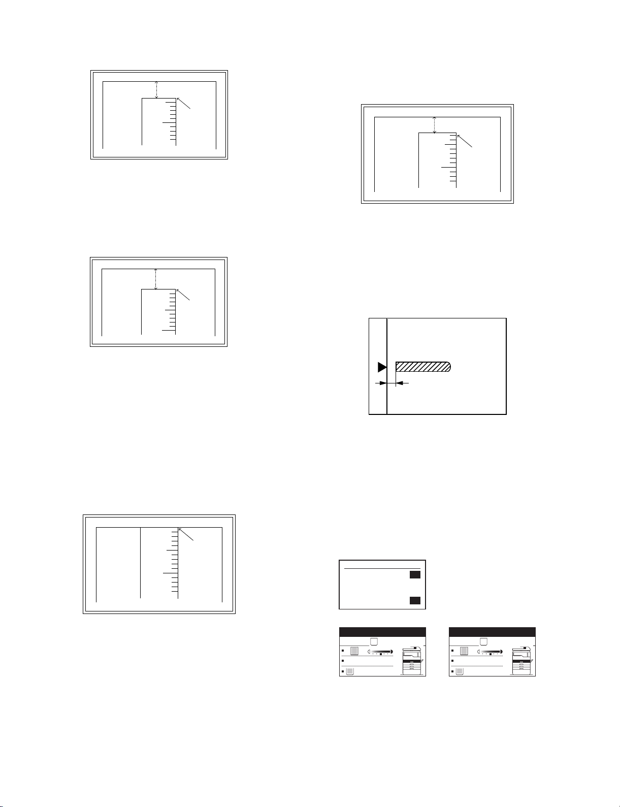
7) Set the main cassette print st art position value (TRAY1) to [1] and
make a copy.
The print start position is shifted inside the document edge.
5mm
5
4mm
10
10) Set the lead edge void adjustment value (DEN-A)* again.
•1 step of the set value corresponds to about 0.1mm shift.
•Calculate the set value from the formula below.
B/0.05 (mm) = Lead edge void adjustment value
<B: Lead edge void (mm)>
2.5mm
*The dimension varies depending on the model.
8) Measure the image loss R of the copied image. Enter the set value of
the image scanning lead edge position (RRC-A) again.
•1 step of the set value corresponds to about 0.1mm shift.
•Calculate the set value from the formula below.
R/0.1(mm) = Image loss set value
<R: Image loss measurement value (mm)>
5mm
5
10
* The scanning edge is set.
(A line may be printed by scanning the document edge.)
0mm
Example: 4/0.1 = 40 = about 40
Note:If the set value is not obtained from the above formula, perform the
fine adjustment.
9) Measure the distance H between the paper lead edge and the image
print start position. Set the image print start position set value
(TRAY1) again.
•1 step of the set value corresponds to about 0.1mm shift.
•Calculate the set value from the formula below.
H/0.1(mm) = Image print start position set value
<H: Print start position measurement value (mm)>
0mm
5
10
0mm
5
10
2.5mm
Example: When setting the lead edge void to 2.5mm
:2.5 /0.05 = about 50
Note: If the s et value is not obtained from the above formula, perform the
fine adjustment.
b.SPF image lead edge position adjustment (SIM50-6)
1) Set a scale on the OC table as shown below.
Note:Since the printed copy is used as a test chart, put the scale in
parallel with the edge lines.
2) Make a copy, Then us e the copy output as an original to make an
SPF copy again.
3) Check the copy output. If necessary, perform the following
adjustment procedures.
4) Execute SIM 50-6.
5) Set the SPF lead edge p osition set value (SIDE1) so that the same
image is obtained as that obtained in the previous OC image lead
edge position adjustment.
(Mode selection window)
Sim50-6 SPF EDGE
1:SIDE1
2:SIDE2
3:END EDGE
[ 1- 99]
50
50
50
50
*Fit the print edge with the paper edge, and perform the
lead edge adjustment.
Example: 5/0.1 = 50 = about 50
Note:If the set value is not obtained from the above formula, perform the
fine adjustment.
AR-M207 M165 M162 ADJUSTMENT 6-3
(Copy start window)
Ready to copy.
S
100%
8 1/2X11
(Copy execution window)
Copies in progress.
S
100%
8 1/2X1
Page 31

<Adjustment specification>
Adjustment mode SIM Display
Set value Spec value Set
text
range
array
SPF image lead
edge position
(1st print surface)
SIM
50-6
SIDE1 1 step:
0.1mm
shift
Lead edge
void:
1 - 4mm
1 - 99
Image loss:
3mm or
less
c.Rear edge void adjustment (SIM50-1, SIM50-19)
1) Set a scale as shown in the figure below .
A4(8.5" x 11")
Paper rear edge
2) Set the document size to A4 (8.5" x 11"), and make a copy at 100%.
3) If necessary, perform the following adjustment procedure.
Void amount (Standard value: 4mm or less)
d. Paper off center adjustment (SIM50-10)
1) Set a test chart (UKOG-0089CSZZ) on the document table.
2) Select a paper feed port and ma ke a copy. Compare the copy and
the test chart. If necessary, perform the following adjustment
procedure.
3) Execute SIM 50-10. After completion of warm-up, shading is
performed and the currently set off center adjustment value of each
paper feed port is displayed.
Sim50-10
1:TRAY1
2:TRAY2
3:TRAY3
1/2 [ 1- 99]
PRT. CENTER
Sim50-10
50
50
50
50
4:TRAY4
5:BYPASS
6:DUPLEX
2/2 [ 1- 99]
PRT. CENTER
50
50
50
50
4) Enter the set value and press the start key. The correction value is
stored and a copy is made.
<Adjustment specification>
Adjustment
mod
Tray 1 SIM
Tray 2 T RAY2
Tray 3 T RAY3
Tray 4 T RAY4
Manual paper
feed tray
Duplex
SIM Display
text array
TRAY1 Add 1:
50-10
BYPASS
DUPLEX
Set value Specifi-
cation
Single:
0.1mm shift
to R side.
Center
±2.0mm
Reduce 1:
0.1mm shift
to L side.
Set
range
1 - 99
(Second print
surface)
Scale image
Paper rear edge
4) Execute SIM50-01 and select “DEN-B” with the arrow keys.
The currently set adjustment value is displayed.
5) Enter the set value and press the start key. The correction value is
stored and a copy is made.
<Adjustment specification>
Mode SIM Display
Rear edge void SIM
50-1
text array
DEN-B 1 step:
Set value Specifi-
cation
4mm or
0.1mm shift
less
Set
range
1 - 99
e.Side edge void area adjustment (SIM26-43)
Note: Before performing this adjustment, be sure to check that the paper
off center adjustment (SIM 50-10) is completed.
1) Set a test chart (UKOG-0089CSZZ) on the document table.
2) Select a paper feed port and ma ke a copy. Compare the copy and
the test chart. If necessary, perform the following adjustment
procedure.
3) Execute SIM 26-43 and set the density mode to SIDE VOID (L),
SIDE VOID (R).
The currently set adjustment value is displayed.
Sim26-43 SIDE VOID
1:SIDE VOID(L)
2:SIDE VOID(R)
[ 0- 10]
3
3
3
4) Enter the set value and press the start key. The correction value is
stored.
<Adjustment specification>
Adjustment
mode
Side void (left) 26-43 SIDE
SIM Display
text array
VOID (L)
Set value Specifi-
cation
1 step:
0.5 - 4mm 1 - 99
0.5mm shift
Set
range
Side void (right) SIDE
VOID (R)
AR-M207 M165 M162 ADJUSTMENT 6-4
Page 32

(2) Main scanning direction(FR direction) distortion balance
adjustment
1) Remove the OC glass and the right cabinet.
(1)
4) Loosen the set screw of the scanner drive pulley which is not in
contact with No. 2/3 mirror base unit positioning plate.
5) Without moving the scanner drive pulley shaft, manually turn the
scanner drive pulley until the positioning plate is brought into contact
with No. 2/3 mirror base unit, then fix the scanner drive pulley.
(2)
(1)
(3)
2) Loosen the copy lamp unit wire fixing screw.
Wire fixing screw
(3)
(4)
6) Put No. 2/3 mirror base unit on the positioning plate again, push the
projections on the front frame side and the rear frame side of the
copy lamp unit to the corner frame, and tighten the wire fixing screw.
3) Manually turn the mirror base dr ive pulley and bring No. 2/3 mirror
base unit into contact with the positioning plate. At that time, if the
front frame side and the rear frame side of No. 2/3 mirror base unit
are brought into contact with the positioning plate at the same time,
the mirror base unit parallelism is proper. If one of them is in contact
with the positioning plate, perform the adjustment of 4).
AR-M207 M165 M162 ADJUSTMENT 6-5
Page 33

(3) Main scanning direction (FR direction) distortion
adjustment
This adjustment must be performed in the following cases:
•When the mirror base drive wire is replaced.
•When the lamp unit, or No. 2/3 mirror holder is replaced.
•When a copy as shown is made.
La
Paper exit
direction
Original
Copy
Lb
4) Loosen the mirror base drive pulley fixing screw on the front frame
side or on the rear frame side.
When La < Lb
Turn the mirror base drive pulley on the front frame side in the
arrow direction A.
(Do not move the mirror base drive pulley shaft.)
When La > Lb
Turn the mirror base drive pulley on the rear frame side in the
arrow direction A.
(Do not move the mirror base drive pulley shaft.)
Rear side
A
B
1) Set A3 (11" x 17") white paper on the original table as shown below.
Allow a little space.
Glass holding plate
Fit the paper edge and
the glass holding plate edge.
A3 (11" x 17") white paper
2) Open the original cover and make a normal (100%) copy.
3) Measure the width of the black background at the lead edge and at
the rear edge.
Front side
5) Tighten the mirror base drive pulley fixing screw.
<Adjustment specification>
La = Lb
6) Execute the main scanning direction (FR) distortion balance
adjustment previously described in 2) again.
(4) Main scanning direction (FR direction) magnification
ratio adjustment (SIM 48-1)
Note: Before performing this adjustment, be sure to check that the CCD
unit is properly installed.
1) Put a scale on the original table as shown below.
Paper exit direction
La: Lead edge black background width
Lb: Rear edge black background width
If the width (La) of the black background at the lead edge is equal that
(Lb) at the rear edge, there is no need to execute the following
procedures of 4) - 7).
AR-M207 M165 M162 ADJUSTMENT 6-6
2) Execute SIM 48-1.
3) After completion of warming up, shading is operated and the current
correction value of the main scanning direction magnification ratio is
displayed on the screen.
Sim48-1 COPY MAG.
1:F-R
2:SCAN
[ 1- 99]
50
50
50
4) Enter the set values of the items of F and R, and press [START] key.
The correction values are saved and a copy is made.
Page 34

<Adjustment specification>
Note: A judgment must be made with 200mm width, and must not be
made with 100mm width.
Adjustment mode SIM Display
text array
Main scanning
48-1 F-R +1
direction magnification ratio
Set
value
+0.1%
-1
Specifications
Normal ±
1.0%
Set
range
1 - 99
0.1%
1) Put a scale on the original table as shown below, and make a normal
(100%) copy to make a test chart.
(5) Sub scanning direction (scanning direction)
magnification ratio adjustment (SIM 48-1, SIM 48-5)
a. OC mode in copying (SIM48-1)
Note: Before performing this adjustment, be sure to check that the CCD
unit is properly installed.
1) Put a scale on the original table as shown below, and mak e a normal
(100%) copy.
2) Compare the scale image and the actual image. If necessary,
perform the following adjustment procedures.
3) Execute SIM 48-1.
4) After completion of warming up, shading is operated and the current
correction value of the sub scanning direction magnification ratio is
displayed on the screen.
Sim48-1 COPY MAG.
1:F-R
2:SCAN
[ 1- 99]
5) Select [2.SCAN] mode with the cross cursor.
Sim48-1 COPY MAG.
1:F-R
2:SCAN
[ 1- 99]
6) Enter the set value and press the start key.
The set value is stored and a copy is made.
<Adjustment specification>
Adjustment mode SIM Display
text array
Sub scanning
48-1 SCAN +1
direction
magnification ratio
OC mode
b. RSPF sub scanning direction magnification ratio (SIM48-5)
Note:
•Before performing this adjustment, be sure to check that the CCD unit is
properly installed.
•Before performing this adjustment, the OC mode adjustment in copying
must be completed.
50
50
50
50
50
50
Set
value
+0.1%
-1
0.1%
Specifications
Normal ±
1.0%
Set
range
1 - 99
Note:Since the printed copy is used as a test chart, put the scale in
parallel with the edge lines.
2) Set the test chart on the SPF and make a normal (100%) copy .
3) Compare the scale image and the actual image. If necessary,
perform the following adjustment procedures.
4) Execute SIM 48-5.
5) After warm-up, shading is performed.
6) Check to confirm that the RSPF (SIDE1) mode is selected with the
cross cursor.
Sim48-5 (R)SPF ZOOM
1:RSPF(SIDE1)
2:RSPF(SIDE2)
[ 1- 99]
50
50
50
7) Enter the set value and press the start key.
The set value is stored and a copy is made.
<Adjustment specification>
Adjustment mode SIM Display
text array
Sub scanning
direction
48-5 RSPF
(SIDE1)
magnification
ratio
Set
value
+1
+0.1%
-1
0.1%
Specifications
Normal ±
1.0%
Set
range
1 - 99
(Front surface)
Sub scanning
direction
RSPF
(SIDE2)
magnification
ratio
(Back surface)
* “RSPF (SIDE2)” is displayed only when the RSPF is installed.
(6) Off center adjustment (SIM 50-12)
a. OC mode (SIM50-12)
1) Make a test chart as shown below and set it so that its cent er line is
fit with the original guide center mark.
* To mak e a test chart, draw a line on A3 or 11" x 17" paper at the center
in the paper transport direction.
Original guide
Center
Copy paper
(A3 or 17" x 11")
2) Make a normal copy from the manual paper feed tray, and compare
the copy and the test chart.
If necessary, perform the following adjustment procedures.
3) Execute SIM 50-12.
AR-M207 M165 M162 ADJUSTMENT 6-7
Page 35

4) After completion of warming up, shading is performed and the
current off-center adjustment value is displayed on the LCD.
Sim50-12
ORG. CENTER
1:OC
2:SPF(SIDE1)
3:SPF(SIDE2)
[ 1- 99]
50
50
50
50
5) Enter the set value and press the start key.
The set value is stored and a copy is made.
<Adjustment specification>
Adjustment
mode
Document offcenter (OC
mode)
SIM Display
Set value Specifi-
text array
50-12 OC +1
Shifted to R
side by
cations
Center ±
2.0%
Set
range
1 - 99
+0.mm.
-1
Shifted to L
side by
0.1mm.
(7) SPF whit e correction pixel position adjustment(SIM63-7)
(required in an SPF model when replacing the lens unit)
1) Fully open the SPF.
2) Execute SIM 63-7.
(Initial window)
Sim63-7 SPF ADJ.
WHITE ADJUST
PRESS OK KEY EXEC
Failure
Sim63-7 SPF ADJ.
WHITE ADJUST
ERROR
[---]
PRESS OK KEY EXEC
3) Slide the lens unit toward the rear side and attach it,then execute
SIM.
F
R
* Wh en the lens unit is moved, execute the Main scanning direction
(SIM48-1,F-R), off center adjustment(SIM50-12) and the PF original
off-center adjustment.
* This adjustment is basically O.K. with SIM 63-7.
C.Image density adjustment
(1)Copy mode (SIM 46-1)
1) Set a test chart (UKOG-0162FCZZ) on the OC table as shown below .
2) Put several sheets of A3 or 11" x 17" white paper on the test chart.
3) Execute SIM 46-1.
4) After completion of warming up, shading is performed, and the
current density level is displayed on the LCD.
OK/START
(Execution window)
Sim63-7 SPF ADJ.
WHITE ADJUST
Success
EXEC
Sim63-7 SPF ADJ.
WHITE ADJUST
COMPLETE
[160]
PRESS OK KEY EXEC
3) When [COMPLETE] is displayed on the LCD, the process is
completed.
4) If the operation panel displays "ERROR,"perform the following
measures.
•When the display is --:
Check that the SPF is open.
Check that th e lamp is ON.(If the la mp is OF F, check the MCU conne cto r.)
Check that the CCD harness is properly inserted into the MCU
connector.
•When the display is 281 or above:
1) Remove the table glass.
2) Remove the dark box.
3) Slide the lens unit toward the front side and attach it, then execut e
SIM.
•When the display is 143 or below:
1) Remove the table glass.
2) Remove the dark box.
Sim46-1 EXP LEVEL
1:AE
2:TEXT
3:PHOTO 1
1/2 [ 1- 99]
50
50
50
50
Sim46-1 EXP LEVEL
4:PHOTO 2
5:TEXT(TS)
6:AE(TS)
2/2 [ 1- 99]
50
50
50
50
Use the cross cursor to select a mode.
5) Change the set value with the 10-key to adjust the copy image
density.
6) Make a copy and check that the specification below is satisfied.
<Adjustment specification>
Density
Automatic
Text TEXT 3 “3” is slightly
Photo
(Error
Display
mode
text
array
Expo-
sure
level
AE - “2” is slight ly
PHOTO
3 “2” is slightly
1
Sharp Gray
Chart output
copied.
copied.
copied.
Set value Set
The greater the set
value is, the darker
the density is.
The smaller the set
value is, the lighter
the density is.
range
1 - 99
diffusion)
Photo
(Dither)
Toner
save
PHOTO
2
TEXT
(TS)
3 “2” is slightly
copied.
3 “3” is slightly
copied.
(Text)
Toner
save
AE(TS) - “2” is slight ly
copied.
(Automatic)
AR-M207 M165 M162 ADJUSTMENT 6-8
Page 36

[7] SIMULATIONS
1. Entering the simulation mode
Perf orm the follo wing procedure to enter the simulation mode.
"#" key “*“ key "C" key “*“ key
Main code Start key Sub code Start key
2. Canceling the simulation mode
When the clear all key is pressed, the simulation mode is cancelled.
When the interruption key is pressed, the process is interrupted and the
screen returns to the sub code entering display.
* After canceling the simulation mode, be sure to turn OFF/ON the
power and check the operation.
Note: If the machine is terminated by a jam error or pa per empty du ring
copying in the adjustment by the simulation, recopying is required.
Note: The values in the simulation columns are not default values but
sample values.
3. List of simulations
Main
Sub
code
code
01 01 Mirror scanning operation
02 Mirror home position sensor (MHPS) status display
02 01 Single paper feeder (SPF) aging *2
02 SPF sensor status display *2
03 SPF motor operation check *2
08 SPF paper feed solenoid operation check *2
09 RSPF reverse solenoid operation check *2 *3
10 RSPF paper exit gate solenoid operation check *2 *3
11 SPF PS release solenoid operation check *2
03 02 Shifter/job separator sensor status display
03 Shifter operation check
04 Job separator operation check *4
11 Shifter home position check
05 01 Operation panel display check
02 Fusing lamp and cooling fan operation check
03 Copy lamp lighting check
06 01 Paper feed/transport solenoid operation check
02 Resist roller solenoid (RRS) operation check
10 Main cassette semicircular roller cleaning
07 01 Warm-up display and aging with jam
06 Intermittent aging
08 Shifting with warm-up display
08 01 Developing bias output
02 Main charger output (Grid = HIGH)
03 Main charger output (Grid = LOW)
06 Transfer charger output
09 01 Duplex motor forward rotation check *6
02 Duplex motor reverse rotation check *6
04 Duplex motor RPM adjustment *6
05 Duplex motor switchback time adjustment
10 - Toner motor operation
14 - Trouble cancel (except for U2)
16 - U2 trouble cancel
20 01 Maintenance counter clear
21 01 Maintenance cycle setting
22 01 Counters display
03 Jam memory display
04 Jam total counter display
07 Key operator code display
09 Paper feed counter display
13 CRUM destination display *5
14 P-ROM version display
15 Trouble memory display
22 SPF jam counter display *2
24 01 Jam total counter clear
02 Trouble memory clear
04 SPF counter clear *2
05 Duplex print counter clear *6
06 Paper feed counter clear
07 Drum counter clear
08 Copy counter clear
09 Printer counter clear
13 Scanner counter clear
14 SPF jam total counter clear *2
15 Scanner mode counter clear
Contents
AR-M207 M165 M162 SIMULATIONS 7-1
Page 37

Main
code
Sub
code
25 01 Main motor operation check (Cooling fan motor rotation
check)
10 Polygon motor operation check
26 01 Job separator setting
02 Size setting
03 Auditor setting
04 Copier duplex setting
05 Count mode setting
06 Destination setting
07 Machine condition check
18 Toner save mode setting
20 Job separator paper exit mode setting
22 Language setting clear
30 CE mark conformity control ON/OFF
31 Auditor mode exclusive setup
36 Cancel of stop at maintenance life over
37 Cancel of stop at developer life over
39 Memor y capacity check
42 Transfer ON/OFF timing control setting
43 Side void amount setting
51 Copy temporary stop function setting
54 LCD contrast PWM duty setting
60 FAX mode key Enab le/Disab le setting
73 Toner save setting display/non-display
74 Total counter display change setting
30 01 Paper sensor status display
41 01 Document size detection photo sensor check
02 Document size detection photo sensor detection level
adjustment
03 Document size detection photo sensor light receiving/
detection level check
04 Detection level adjustment when the document size is
settled(15degrees - 20degrees)
42 01 Developing counter clear
43 01 Fusing temperature setting (Normal copy)
12 Standby mode fusing fan rotation setting
13 Fusing paper interval control allow/inhibit setting
44 34 Transfer current setting
40 Setting of rotation time before toner supply
46 01 Copy density adjustment (300dpi)
02 Copy density adjustment (600dpi)
09 Copy exposure level adjustment, individual setting
(Text) 300dpi
10 Copy exposure level adjustment, individual setting
(Text) 600dpi
11 Copy exposure level adjustment, individual setting
(Photo) 600dpi
18 Image contrast adjustment (300dpi)
19 Exposure mode setting
(Gamma table setting/AE operation mode setting/
Photo image process setting)
20 SPF exposure correction *2
29 Image contrast adjustment (600dpi)
30 AE limit setting
31 Image sharpness adjustment
48 01 Main/sub scanning magnification ratio adjustment
05 SPF/RSPF mode sub scanning magnification ratio
adjustment in copying *2
49 01 Flash ROM program writing mode
Contents
Main
Sub
code
code
50 01 Image lead edge adjustment
06 Copy lead edge position adjustment (SPF/RSPF) *2
10 Paper off-center adjustment
12 Document off-center adjustment
18 Memory reverse position adjustment in duplex copy *1
19 Rear edge void adjustment in duplex copy *6
51 02 Resist amount adjustment
53 08 SPF scanning position automatic adjustment *2
10 SPF scanning position setting
61 03 HSYNC output check
63 01 Shading check
07 SPF automatic correction *2
64 01 Self print
65 10 Key reception time setting display/non-display setting
11 Info lamp setting
67 50 USB reception speed adjustment
<Execution inhibit conditions>
*1) Execution is inhibited when the duplex setup is OFF and other than
RSPF is set.
*2) Execution is inhibited when OC.
*3) Execution is inhibited when SPF. (Not RSPF)
*4) Execution is inhibited when the job separator is not installed.
*5) Execution is inhibited when the model is not provided with the
CRUM.
*6) Execution is inhibited when the duplex setup is OFF.
Contents
AR-M207 M165 M162 SIMULATIONS 7-2
Page 38

4. Contents of simulations
Main
code
01 01 Mirror scanning operation
Sub
code
Used to check the operations of the scanner unit and its control circuit.
Enter the number of times and the magnification ratio, and press [OK] key to operate the scanner unit. The
speed is variable according to the specified magnification ratio. The number of scanning can be specified by
entering a value to the right lower section of the LCD.
•Setting range of magnification ratio: 25%-400%
•Setting range of the number of scanning: 0-999 (When 0 is set, it means unlimited. )
(Scan number input window)
Sim1-1 SCAN CHECK
115%
100%
86%
ZOOM 100% 5
(Execution
window)
Sim1-1 SCAN CHECK
115%
100%
86%
ZOOM 100% EXEC
MHPS
OK/START Key
MHPS
123
123
Contents Remark
Set the scan magnification ration.
This magnification ratio accords with the scan speed
in actual copying. The setting range is 25% - 400%.
Specify the scan number to be performed.
The setting range is 0 - 999. When 0 is set,
the number is unlimited.
MHPS sensor status
Scan counter
Highlighted during execution
Used to display the status (ON/OFF) of the mirror HP sensor on the LCD during scanning. (Highlighted at
ON)
"EXEC" is displayed to indicate execution is in process. The scan counter is displayed above "EXEC." This
counter is counted up even in simulation.
The copy lamp is lighted during scanning.
[CA] key: Exits the simulation mode.
[Interruption] key: Returns to the sub code input window.
[C] key: Input value clear
10 key: Input of the number of scanning
02 Mirror home positions sensor (MHPS) status display
Used to monitor the mirror home position sensor and display the ON/OF status of the sensor on the LCD.
Sim1-2 SENSOR CHECK
MHPS
MHPS(MIRROR HOME POSITION SENSOR)
ON :Highlight display
OFF :Normal display
[CA] key: Exits the simulation mode.
[Interruption] key: Returns to the sub code input window.
AR-M207 M165 M162 SIMULATIONS 7-3
Page 39

Main
code
Sub
code
02 01 Single Paper Feeder(SPF)aging
Used to check the operations of the SPF unit and its control circuit.
Enter the magnification ratio and press OK or [STAR T ] key to drive the SPF unit at the speed corresponding
to the setting.
(Magnification ratio selection window)
Sim2-1 SPF AGING
115%
100%
86%
ZOOM 100% EXEC
(Execution
window)
Sim2-1 SPF AGING
115%
100%
86%
ZOOM 100% EXEC
1SIDE
2SIDE
OK/START Key
1SIDE
2SIDE
* When [ Interruption] key is press, the simulation is terminated and the machine returns to the sub code
input window .
* W hen [CA] key is pressed, the simulation is terminated and the machine exits the simulation mode.
02 SPF sensor status display
Contents Remark
Select the scan magnification ratio (drive speed).
This also accords with the magnification ratio and
the speed in copying similarly to the OC.
The setting range is 50% - 200%.
"EXEC" is highlighted during execution.
Used to display the sensor status in the SPF/RSPF section. An active sensor is highlighted.
Sim2-2 SENSOR CHECK
SPFP
OCCV
POUT
SPFC
L1
L2
W0
W1
W2
W3
Displayed name : Sensor name
SPFP :SPF document transportation sensor
OCCV :SPF unit (OC cover) open/close sensor
POUT :SPF paper exit sensor
SPFC :SPF paper feed cover open/close sensor
L1 :SPF paper length sensor 1
L2 :SPF paper length sensor 2
W0 :SPF document set sensor
W1 :SPF paper width sensor (small)
W2 :SPF paper width sensor (middle)
W3 :SPF paper width sensor (large)
[CA] key: Exits the simulation mode.
[Interruption] key: Returns to the sub code input window.
03 SPF motor operation check
Used to check the operation of the SPF motor and its control circuit. When this simulation is executed, the
initial menu shown below is displayed. Select the magnification ratio to drive the motor.
(Initial window = Magnification ratio selection window)
Sim2-3 OUTPUT CHECK
115%
100%
86%
ZOOM 100% EXEC
OK/START Key
(Execution
window)
Sim2-3 OUTPUT CHECK
115%
100%
86%
ZOOM 100% EXEC
Select the scan magnification ratio (drive speed).
This also accords with the magnification ratio and
the speed in copying.
The setting range is 50% - 200%.
"EXEC" is highlighted during execution.
[CA] key: The SPF motor is stopped, and the machine exits the simulation mode. [Interruption] ke y: The SPF
motor is stopped, and the machine returns to the sub code input window.
AR-M207 M165 M162 SIMULATIONS 7-4
Page 40

Main
code
Sub
code
02 08 SPF paper feed solenoid operation check
Used to drive the SPF paper feed solenoid (PSOL) 20 times in the cycle of 500msec of "ON" and 500msec
of "OFF." After completion of the process, the machine returns to the sub code input window.
(Initial window) (Execution window)
Sim2-8 SPUS CHECK
OK/START Key
Contents Remark
Sim2-8 SPUS CHECK
PRESS OK KEY EXEC
EXEC
When [Interruption] key is pressed, the machine returns to the sub code input window.
When [CA] key is pressed, the machine exits the simulation mode.
09 RSPF reverse solenoid operation check
Used to drive the SPF reverse solenoid (RSOL) 20 times in the cycle of 500msec of "ON" and 500msec of
"OFF." After completion of the process, the machine returns to the sub code input window.
(Initial window) (Execution window)
Sim2-9 SPFS CHECK
PRESS OK KEY EXEC
OK/START Key
Sim2-9 SPFS CHECK
EXEC
When [Interruption] key is pressed, the machine returns to the sub code input window.
When [CA] key is pressed, the machine exits the simulation mode.
10 RSPF paper exit gate solenoid operation che ck
Used to drive the SPF paper exit gate solenoid (GSOL) 20 times in the cycle of 500msec of "ON" and
500msec of "OFF." After completion of the process, the machine returns to the sub code input window.
(Initial window) (Execution window)
Sim2-10 SGS CHECK
PRESS OK KEY EXEC
OK/START Key
Sim2-10 SGS CHECK
EXEC
When [Interruption] key is pressed, the machine returns to the sub code input window.
When [CA] key is pressed, the machine exits the simulation mode.
11 SPF PS release solenoid operation check
Used to drive the SPF PS release solenoid (CLH) 20 times in the cycle of 500msec of "ON" and 500msec of
"OFF." After completion of the process, the machine returns to the sub code input window.
(Initial window) (Execution window)
Sim2-11 CLH CHECK
PRESS OK KEY EXEC
OK/START Key
When [Interruption] key is pressed, the machine returns to the sub code input window.
When [CA] key is pressed, the machine exits the simulation mode.
03 02 Shifter/job separator sensor status display
Used to monitor the sensors related to the shifter and the job separator and display the sensor status on the
LCD. An activ e sensor is highlighted.
Sim3-2 SENSOR
SFTHP
TRYF
JSUP
TRYD
JSDL
Displayed name :Sensor name
SFTHP :Shifter home position sensor
JSUP :Job separator upper limit sensor
JSDL :Job separator lower limit sensor
TRYF :Tray full sensor
TRYD : Paper exit sensor
* Displayed only when the job separator is installed except for SFTH.
Sim2-11 CLH CHECK
EXEC
AR-M207 M165 M162 SIMULATIONS 7-5
Page 41

Main
code
Sub
code
03 03 Shifter operation check
Used to reciprocate the shifter 4 times.
During execution, the status of the shifter HP sensor is displayed on the right upper section of the screen.
(When the sensor is detected, the display is highlighted.)
[CA] key: Exits the simulation mode.
[Interruption] key: Returns to the sub code input window.
* When t he above end key is pressed during operation of the shifter, the shifter is returned to the home
position before terminating the operations.
(Initial window) (Execution window)
Sim3-3 SHIFTER CHK
OK/START Key
Contents Remark
Sim3-3 SHIFTER CHK
SFTHP
PRESS OK KEY EXEC
EXEC
04 Job separator operation check
Used to operate the job separator up and down for 30sec.
During operation, the status of the upper limit sensor and the lower limit sensor is displayed on the right
upper section of the display.
[CA] key: Exits the simulation mode.[Interruption] key: Returns to the sub code input window.
When the operation is interrupted, the job separator is shifted to the home position before terminating the
simulation similarly to the shifter.
(Initial window) (Execution window)
Sim3-4 JOBSEPA CHK
PRESS OK KEY EXEC
OK/START Key
Sim3-4 JOBSEPA CHK
JSUP
JSDL
EXEC
Display name Sensor name
JSUP :Job separator upper limit sensor
JSDL :Job separator lower limit sensor
11 Shifter home position check
Used to check the operations of the shifter HP sensor and the shifter. When this simulation is executed, the
initial menu is displayed. By the following key operations, the left operation and the right operation of the
home position sensor and the shifter can be executed separately.
[ ] key: Shifts to R side by the specified steps.
[ ] key: Shifts to F side by the specified steps.
[ ] key: Shift to the home position.
[SFTHP] is highlighted when the HP sensor is detected.
(Initial window)
Sim3-11 SHIFTER CHK
SFTHP
[ ]:R [ ]:HP [ ]:F
[CA] key: Exits the simulation mode.
[Interruption] key: Returns to the sub code input window.
AR-M207 M165 M162 SIMULATIONS 7-6
Page 42

Main
code
Sub
code
05 01 Operati on panel display check
<LED/LCD check mode>
Used to check the operations (ON, display) of the LED and the LCD on the operation panel.
When this simulation is executed, all LED's on the operation panel (including 7SEG) are lighted and
checking LCD is started.
For the operation check of LCD, the area is divided into two sections; upper section and lower section, and
the display cycle of Normal Dark Light Off is repeated in each section. Each display period is
2sec.
Contents Remark
Normal
Sim5-1 LCD/LED CHK.
Normal
Sim5-1 LCD/LED CHK.
Off
Sim5-1 LCD/LED CHK.
Dark
Sim5-1 LCD/LED CHK.
Dark
Sim5-1 LCD/LED CHK.
Sub code input standby window
Light
Sim5-1 LCD/LED CHK.
Light
Sim5-1 LCD/LED CHK.
When [Interruption] key is pressed in the LED check mode, the machine returns to the sub code input
window.
When [CA] key is pressed, the machine exits the simulation mode.
When [START] key is pressed during LCD display, the machine goes to the key input check mode.
<Key input check mode>
Used to check that the keys on the operation panel are properly detected.
When the machine enters the key input check mode, the initial menu is displayed.
(Initial window)
Sim5-1 LCD/LED CHK.
0
When any key is pressed, the value on the right lower side is counted up.
If a key is pressed once, it is not counted again.
When [CA] key is pressed for the first time, it is counted. When it is pressed for the second time, the
simulation mode is terminated.
When [Interrupt] key is pressed for the first time, it is counted. When it is pressed for the second time, the
window returns to the sub code input standby window.
* Note for the key input check mode
[Start] key must be pressed at the end. If it is pressed midway, the simulation judges that the last key is
pressed and terminates the check mode. Multi input of tow or more keys is ignored.
AR-M207 M165 M162 SIMULATIONS 7-7
Page 43

Main
code
Sub
code
05 02 Fusing lamp and cooling fan operation che ck
Used to check the operations of the heater lamp and the cooling fan and the peripheral circuits.
When this simulation is executed, the following initial menu is displayed.
(Initial window) (Execution window)
Sim5-2 HT LAMP
OK/START Key
Contents Remark
Sim5-2 HT LAMP
PRESS OK KEY EXEC
When this simulation is executed, the fusing lamp repeats ON/OFF 5 times in the cycle of 500ms.
The cooling fan motor is rotated during that period. (The cooling fan, however, is rotated for about 8sec.)
After completion of the operation, the machine returns to the sub code input window.
03 Copy lamp lighting check
Used to check the operations of the copy lamp and its peripheral circuit.
When this simulation is executed, the following initial menu is displayed.
(Initial window) (Execution window)
Sim5-3 COPY LAMP
PRESS OK KEY EXEC
OK/START Key
When [OK] key or [START] key is pressed, the copy lamp is lighted for about 5sec.
After passing for 5sec, the machine returns to the sub code input window.
06 01 Paper feed/transport solenoid operation check
When this simulation is ex ecuted, the names of the solenoids which can be operated are displayed. Select a
load to be operated with the 10-key.
(Load selection window)
Sim6-1 OUTPUT CHECK
1:CPSOL
2:PSOL1
3:PSOL2
(Load selection window)
Sim6-1 OUTPUT CHECK
1:CPSOL
2:PSOL1
3:PSOL2
4:PSOL3
5:HPSOL
6:FSOL2
EXEC1/2 1
10Key
4:PSOL3
5:HPSOL
6:FSOL2
EXEC1/2 2
1: CPSOL :Cassette 1 paper feed solenoid
2: PSOL1 :Cassette 2 paper feed solenoid (*)
3: PSOL2 :Cassette 2 paper feed solenoid (*)
4: PSOL3 :Cassette 3 paper feed solenoid (*)
5: HPSOL :Manual feed tray paper feed solenoid
6: FSOL2 :Cassette 2 transport solenoid (*)
7: FSOL3 :Cassette 3 transport solenoid (*)
(*) Supported only for the model with the option installed.
Skipped for the other models without installation.
After completion
of execution
EXEC
Sim5-3 COPY LAMP
EXEC
(Execution window)
OK/START Key
Sim6-1 OUTPUT CHECK
1:CPSOL
2:PSOL1
3:PSOL2
4:PSOL3
5:HPSOL
6:FSOL2
EXEC1/2 2
During execution, the selected solenoid repeats
ON/OFF 20 times for every 500ms.
02 Resist roller solenoid (RRS) operation check
When this simulation is executed, the machine goes to the execution start window. When [OK] key or
[START] key is pressed, the resist roller solenoid (RRS) repeats ON of 500ms and OFF of 500ms 20 times.
(Execution start window) (Execution window)
Sim6-2 RRS CHECK
PRESS OK KEY EXEC
OK/START Key
Sim6-2 RRS CHECK
EXEC
When the operation is completed, the machine returns to the sub code input window.
When [Interruption] key is pressed, the machine returns to the sub code input window. When [CA] key is
pressed, the machine exits the simulation mode.
AR-M207 M165 M162 SIMULATIONS 7-8
Page 44

Main
code
Sub
code
06 10 Main cassette semi circular roller cleaning
Before ex ecution of this simulation, remov e the developing cartridges. When this simulation is executed, the
load select menu is displayed as shown below. Select a roller cassette to be cleaned with the 10-key. When
[OK] key or [START] key is pressed, the semi-circular roller of the specified cassette is rotated halfway round
and stopped with the roller facing downward.
(Load selection window) (Execution window)
Sim6-10 ROLLER CLN
1:TRAY1
2:TRAY2
3:TRAY3
4:TRAY4
EXEC 0
10Key
When [Interruption] key is pressed after cleaning, the machine returns to the sub code input window and the
semi-circular roller returns to the original position.
* When TRAY2 - TRAY4 are not installed, they are not displayed.
* When another cassette roller is cleaned continuously, press [Interruption] key to return the roller to the
original position and restart the simulation.
* When the simulation mode is terminated by pressing [CA] key, the roller returns to the original position by
the initializing operation.
07 01 Warm-up display and agi ng with jam
Used to measure the warm-up time and execute aging with jam.
When this simulation is executed, the following w arm-up window is displayed.
The time required for starting the warm-up and completing the initializing operation and shifting to the standby state is displayed.
After completion of warm-up, press [CA] key to exit the simulation mode, allowing normal copy operations.
The copy mode at that time is the aging mode with 0sec of intermittent aging.
(Warming up window)
Sim7-1 W-UP C-MODE
WARMING UP.
(Warming up completion window)
Contents Remark
Sim6-10 ROLLER CLN
1:TRAY1
2:TRAY2
3:TRAY3
Sim7-1 W-UP C-MODE
WARM UP COMPLETED.
4:TRAY4
EXEC1/2 2
OK/START
Key
CA
Sim6-10 ROLLER CLN
1:TRAY1
2:TRAY2
3:TRAY3
(Copy window)
Ready to copy.
4:TRAY4
EXEC 2
S
1
10
100%
8 1/2
Canceled by turning off the power or executing a simulation which makes the hardware reset. When the
interruption is pressed to shift to the input standby window, the machine does not enter the aging mode.
06 Intermi ttent aging
Used to execute intermittent aging of 3sec. The set quantity and the mode are optionally selected.
When this simulation is executed, the following execution start window is displayed.
When [OK] key or [START] key is pressed, the machine exits the simulation mode.
Enter a desired coy mode and a desired copy quantity.
Press [START] key, and intermittent aging will be started.
(Execution start window)
Sim7-6 INTERVAL SET
AGING INTERVAL
AER YOU SURE? EXEC
(Copy window)
Ready to copy.
S
100%
8 1/2
11
It is canceled by turning off the power or executing a simulation with the hard reset.
11
AR-M207 M165 M162 SIMULATIONS 7-9
Page 45

Main
code
Sub
code
07 08 Shifting w ith warm -up di splay
Used to measure the warm-up time.
When this simulation is executed, the following w arm-up window is displayed.
The time required for starting the warm-up and completing the initializing operation and shifting to the standby state is displayed.
* Though [CA ] key is pressed, the machine does not enter the aging mode of intermission 0 sec.
(Warming up window)
Sim7-8 W-UP C-MODE
WARMING UP.
Contents Remark
(Warming up completion window)
Sim7-8 W-UP C-MODE
WARM UP COMPLETED.
Press [CA] key to exit the simulation mode.
(The aging function is omitted from SIM 07-01.)
08 01 Developing bias output
Used to check the developing bias output.
When this simulation is executed, the following execution start window is displayed.
When [OK] key or [START] key is pressed, the developing bias signal is turned ON for 30sec. When
measuring the actual output value, however, use SIM 25-01.
After completion of the process, the machine returns to the sub code input window.
(Execution start window) (Execution window)
Sim8-1 DV BIAS
PRESS OK KEY EXEC
[CA] key: Exits the simulation mode.
[Interruption] key: Interrupts output operation and shifts to the sib code input window.
02 Main charger output (Grid = HIGH)
Used to check the main charger output.
When this simulation is executed, the following execution start window is displayed.
When [OK] key or [START] key is pressed, the main charger is turned on for 30 sec in the grid voltage HIGH
mode.
After completion of the process, the machine returns to the sub code input window.
(Execution start window) (Execution window)
Sim8-2 MHV(H)
1
OK/START Key
OK/START Key
10
Sim8-1 DV BIAS
EXEC
Sim8-2 MHV(H)
PRESS OK KEY EXEC
EXEC
[CA] key: Exits the simulation mode.
[Interruption] key: Interrupts output operation and shifts to the sub code input window.
03 Main charger output (Grid = LOW)
Used to check the main charger output.
When this simulation is executed, the following execution start window is displayed.
When [OK] key or [START] key is pressed, the main charger is turned on for 30 sec in the grid voltage LOW
mode.
After completion of the process, the machine returns to the sub code input window.
(Execution start window) (Execution window)
Sim8-3 MHV(L)
PRESS OK KEY EXEC
OK/START Key
Sim8-3 MHV(L)
EXEC
[CA] key: Exits the simulation mode.
[Interruption] key: Interrupts output operation and shifts to the sub code input window.
AR-M207 M165 M162 SIMULATIONS 7-10
Page 46

Main
code
Sub
code
08 06 Transfer charger output
When this simulation is executed, the machine shifts to the following mode select window, and the list of the
modes to be outputted is displayed.
Select an output mode with 10-key and press [OK] key or [START] key, and the transfer charger output is
made for about 30sec in the specified mode.
(Mode selection window)
Sim8-6 TC OUTPUT
1:NML_A
2:NML_B
3:SML_A
4:SML_B
5:BYPASS
EXEC
OK/START Key
2
Window display Output mode
1:NML_A Normal size width (front)
2:NML_B Normal size width (back)
3:SML_A Small size width (front)
4:SML_B Small size width (back)
* The back is not displayed when DUPEX setting is OFF.
* Small size paper is Letter R (A4R) width or below. When an output is completed, the machine shifts to the
mode select window.
[CA] key: Exits the simulation mode.
[Interruption] key: Interrupts the output operation, and shifts to the sub code input window.
09 01 Dup lex motor forward rotation check
Used to check the duplex motor rotation.
The duplex motor is rotated in the normal direction (paper exit direction) for 30sec.
After completion of the process, the machine shifts to the sub code input window.
(Execution start window) (Execution window)
Sim9-1 DMF CHECK
OK/START Key
Contents Remark
(Execution window)
Sim8-6 TC OUTPUT
1:NML_A
2:NML_B
3:SML_A
Sim9-1 DMF CHECK
4:SML_B
5:BYPASS
EXEC
2
PRESS OK KEY EXEC
EXEC
[CA] key: Exits the simulation mode.
[Interruption] key: Interrupts the output operation, and shifts to the sub code input window.
02 Duplex motor reverse rotation check
Used to check the duplex motor reverse rotation.
The duplex motor is rotated in the reverse direction for 30sec.
After completion of the process, the machine shifts to the sub code input window.
(Execution start window) (Execution window)
Sim9-2 DMR CHECK
PRESS OK KEY EXEC
OK/START Key
Sim9-2 DMR CHECK
EXEC
[CA] key: Exits the simulation mode.
[Interruption] key: Interrupts the output operation, and shifts to the sub code input window.
AR-M207 M165 M162 SIMULATIONS 7-11
Page 47

Main
code
Sub
code
09 04 Duplex motor RPM adjustment
Used to adjust the duplex motor rotation speed.
When this simulation is ex ecuted, the following setting window is displayed. Enter an input v alue with 10-k e y
and press [OK] key or [START] key.
The setting range is in 1-13 steps and the default is "4" (646.9PPS).
(Setting window)
Sim9-4 MOTOR SPEED
1:MOTOR SPEED
4
4[ 1-13]
When a value outside the setting range is inputted, it is ignored.
[CA] key: Exits the simulation mode.
[Interruption] key: Shift to the sub code input window.
05 Duplex motor switchback time adjustment
Used to adjust the duplex motor switchback time when the motor reverse rotation is controlled.
When this simulation is ex ecuted, the following setting window is displayed. Enter an input v alue with 10-k e y
and press [OK] key or [START] key.
The setting range is 50-76, and the default is 50.
When the adjustment value is increased by 1, the distance up to reverse start is increased by 3 steps in 1-2
phase excitement.
Sim9-5 SW BACK TIME
1:SW BACK TIME
50
Contents Remark
Default:
4(646.9PPS)
Set value : Speed (PPS)
01 : 637.2PPS(Slow)
02 : 640.4PPS
03 : 643.6PPS
04 : 646.9PPS(Default)
05 : 650.1PPS
06 : 653.3PPS
07 : 656.5PPS
08 : 659.8PPS
09 : 662.9PPS
10 : 666.2PPS
11 : 669.4PPS
12 : 672.6PPS
13 : 675.8PPS(Fast)
Default:
50
50[ 50-76]
When a value outside the setting range is inputted, it is ignored.
[CA] key: Exits the simulation mode.
[Interruption] key: Shift to the sub code input window.
10 - Toner motor operation
Used to check the operation of the toner motor.
When this simulation is executed, the following execution start window is displayed. Press [OK] key or
[START] key, and the toner motor is rotated for about 30sec.
After completion of the process, the machine shifts to the sub code input window.
(Execution start window) (Execution window)
Sim10 TONER MOTOR
PRESS OK KEY EXEC
OK/START Key
[CA] key: Exits the simulation mode.
[Interruption] key: Interrupts the output operation, and shifts to the sub code input window.
14 - Trouble cancel (except for U2)
* Used to cancel EEPROM writing troubles such as H trouble and execute the hard reset.
When this simulation is executed, the following execution start window is displayed. Press [OK] key or
[START] key to clear the trouble other than U2.
(Execution start window)
Sim14 TROUBLE CLEAR
TROUBLE CLEAR
(WITHOUT U2)
AER YOU SURE? EXEC
Sim10 TONER MOTOR
EXEC
AR-M207 M165 M162 SIMULATIONS 7-12
Page 48

Main
code
Sub
code
16 - U2 trouble cancel
* Used to cancel the U2 trouble and execute the hard reset.
When this simulation is executed, the following execution start window is displayed. Press [OK] key or
[START] key to clear the U2 trouble.
(Execution start window)
Sim16 TROUBLE CLEAR
U2 TROUBLE CLEAR
AER YOU SURE? EXEC
20 01 Maintenance counter clear
Used to clear the maintenance counter.
Press [OK] key or A[START] key on the following window, the maintenance counter is cleared and the
machine returns to the sub code input window.
Sim20-1 COUNTER CLR
MAINTENANCE COUNTER
CLEAR
AER YOU SURE? EXEC
Contents Remark
21 01 Maintenance cycle setting
Used to set the maintenance cycle. When this simulation is executed, the current set value is displayed.
Enter a desired code with 10-key and press [START] key. The set value is saved in the EEPROM and the
machine returns to the sub code input window.
Sim21-1 CYCLE SET.
1:MAINTE CYCLE
4
4[ 0- 5]
[CA] key: Exits the simulation mode.
[Interruption] key: Returns to the sub code input window.
Default:
4(50k)
0: 5K (5,000 sheets)
1: 7.5K (7,500 sheets)
2: 10K (10,000 sheets)
3: 25K (25,000 sheets)
4: 50K (50,000 sheets)
5: FREE (999,999 sheets)
(Setting range: 0 - 5, Default = 4)
AR-M207 M165 M162 SIMULATIONS 7-13
Page 49

Main
code
Sub
code
22 01 Counters display
Contents Remark
Sim22-1 COUNTER 1/4
TOTAL :nnnnnnn
MAINTE :nnnnnnn
DEV :nnnnnnn(*)
MIN_MNT :nnnnnnn(*)
DRUM :nnnnnnn
Sim22-1 COUNTER 2/4
CPY JOB : nnnnnnn
PRT JOB : nnnnnnn
SCN JOB : nnnnnnn
OC SCN : nnnnnnn
Sim22-1 COUNTER 3/4
SPF : nnnnnnn
DUPLEX : nnnnnnn
OTHERS : nnnnnnn
MNTCYC : nnnnnnn
Sim22-1 COUNTER 4/4
DRM TTL : nnnnnnn
MMTCYC : nnnnnnn
(*) Either of the following two is displayed depending on the model.
DEV: Development counter (EX Japan)
MIN_MNT: Mini maintenance counter (Japan)
Counter display
TOTAL : Total counter
MAINTE : Maintenance counter (AR model)
DEV : Development counter (AR EX Japan model)
MIN MNT : Mini maintenance counter (AR Japan model)
DRUM : Drum counter
CPY JOB : Copy job counter
PRT JOB : Print job counter
SCN JOB : Scan job counter
OC SCN : OC scan counter
SPF : SPF counter
DUPLEX : DUPLEX counter
OTHERS : Other counter
MNTCYC : Maintenance cycle (AR model)
DRM TTL :Drum rotation accumulated time
MMTCYC : Mini maintenance cycle (AR Japan model)
Though SIM26-74 is set to “1: Scan counter is added,” the count is not added to SIM22-01 total counter
display. The setting affects only the total counter display in the key operator program.
03 Jam memory display
Used to check the jam kind occurred in the main unit and the SPF.
The kinds of jams up to 30 items are displayed sequentially from the latest one. (The oldest one is deleted
sequentially.) This display is used for troubleshooting. (If there are extremely many troubles in a position, it
may be judged that a repair must be executed.)
The kinds and contents of jams to be displayed are as follows.
Sim22-3 JAM HIS. 1/4
XXXXXXX XXXXXXX
XXXXXXX XXXXXXX
XXXXXXX XXXXXXX
XXXXXXX XXXXXXX
Sim22-3 JAM HIS. 2/4
XXXXXXX XXXXXXX
XXXXXXX XXXXXXX
XXXXXXX XXXXXXX
XXXXXXX XXXXXXX
Kinds of jams and display contents
SPPD_ON : SPF paper entry sensor (Not reached)
SPPD_OFF : SPF paper entry sensor (Remaining)
SOUT_ON : SPF paper exit sensor (Not reached)
SOUT_OFF : SPF paper exit sensor (Remaining)
POUT_ON : Paper exit sensor (Not reached)
POUT_OFF : Paper exit sensor (Remaining)
DPX_ON : DUP sensor (Not reached)
DPX_OFF : DUP sensor (Remaining)
PIN_ON : Paper feed sensor (Not reached)
PIN_OFF : Paper feed sensor (Remaining)
PIN2_ON : Cassette 2 paper feed sensor (Not reached)
PIN3_ON : Cassette 3 paper feed sensor (Not reached)
PIN4_ON : Cassette 4 paper feed sensor (Not reached)
[CA] key: Exits the simulation mode.
[Interruption] key: Shifts to the sub code input window.
, keys: Switches to another page.
AR-M207 M165 M162 SIMULATIONS 7-14
Page 50

Main
code
Sub
code
22 04 Jam total counter display
Used to display the jam total counter.
Sim22-4 COUNTER
JAM : nnnnnn
07 Key operator code display
Used to display the key operator code.
Sim22-7 KEY OPE
KEY CODE: nnnnn
09 Paper fee d c ounter display
Used to display the paper feed quantity of each paper feed tray. This simulation shows the use frequency of
each paper feed section.
[CA] key: Exits the simulation mode.
[Interruption] key: Shifts to the sub code input window.
, keys: Switches to another page.
Sim22-9 COUNTER 1/2
BYPASS : nnnnnnn
TRAY1 : nnnnnnn
TRAY2 : nnnnnnn
TRAY3 : nnnnnnn
Key
Key
Contents Remark
Sim22-9 COUNTER 2/2
TRAY4 : nnnnnnn
* TRAY2-TRAY4 are displayed only when they are installed.
13 CRUM destination display
Used to display the CRUM chip destination code saved in the EEPROM. If the display does not match the
destination code saved in the CRUM chip, it is judged as an error.
* This simulation is valid only for the model with the CRUM chip.
Sim22-13 CRUM
CRUM TYPE nn
Number : Setting (Destination)
00 : Not set.
01 : BTA-A
02 : BTA-B
03 : BTA-C
04 : BTA-E
12 : AL series
99 : Conversion
14 P-ROM version display
Sim22-14 ROM VER1/2
S/N : ----------MCU : --.-IMC : --.-PNL : --.--
Sim22-14 ROM VER2/2
FAX : --.--
S/N :Production serial number
MCU :Main unit program version
IMC :IMC program version
PNL :Panel program version
FAX :FAX program version
The version of the option board which is not installed is not displayed.
AR-M207 M165 M162 SIMULATIONS 7-15
Page 51

Main
code
Sub
code
22 15 Trouble memory display
The latest 20 troubles are displayed. (The oldest one is overwritten sequentially.)
[CA] key: Exits the simulation mode.
[Interruption] key: Shifts to the sub code input window.
, keys: Switches to another page.
Sim22-15 TROUBLE 1/2 Sim22-15 TROUBLE 2/2
XX-XX XX-XX XX-XX
XX-XX XX-XX XX-XX
XX-XX XX-XX XX-XX
XX-XX XX-XX XX-XX
The display sequence is as shown below.
Sim22-15 TROUBLE 1/2
1
2
3
4
5
6
7
8
In this case, (1) is the latest one and (12) is the oldest.
22 SPF jam counter display
Used to display the SPF JAM counter.
When [Interruption] key is pressed, the machine goes to the sub code input window. When [CA] key is
pressed, the machine exits the simulation mode.
Sim22-22 JAM CNT
SPF : nnnnnnn
Contents Remark
Key
Key
9
10
11
12
XX-XX XX-XX XX-XX
XX-XX XX-XX XX-XX
XX-XX XX-XX
24 01 Jam total counter clear
When this simulation is executed, the clear confirmation window is displayed as shown below.
When [OK] key or [START] key is pressed, the jam total count and the jam memory are cleared and the
machine shifts to the sub code input window.
Sim24-1 COUNTER CLR
JAM COUNTER CLEAR
AER YOU SURE? EXEC
02 Trouble memory clear
Used to clear the trouble memory and the trouble history data in the EEPROM.
When [Interruption] key is pressed, the machine shifts to the sub code input window. When [CA] key is
pressed, the machine exits the simulation mode.
Sim24-2 COUNTER CLR
TROUBLE
CLEAR
AER YOU SURE? EXEC
COUNTER
04 SPF counter c lear
Used to clear the SPF paper feed counter.
Sim24-4 COUNTER CLR
SPF
COUNTER
CLEAR
AER YOU SURE? EXEC
[CA] key: Exits the simulation mode.
[Interruption] key: Shifts to the sub code input window.
AR-M207 M165 M162 SIMULATIONS 7-16
Page 52

Main
code
Sub
code
24 05 Duplex print counter clear
Used to clear the duplex print counter.
Sim24-5 COUNTER CLR
DUPLEX
COUNTER
CLEAR
AER YOU SURE? EXEC
[CA] key: Exits the simulation mode.
[Interruption] key: Shifts to the sub code input window.
06 Paper feed counter clear
Used to clear the paper feed counter data in each paper feed section.
(Initial window (Counter selection window) (Confirmation window)
Sim24-6 COUNTER CLR Sim24-6 COUNTER CLR Sim24-6 COUNTER CLR
1:BYPASS
2:TRAY1
3:TRAY2
4:TRAY3
5:TRAY4
* TRAY2-TRAY4 are displayed only when they are installed.
[CA] key: Exits the simulation mode.
[Interruption] key: Shifts to the sub code input window.
07 Drum counter clear
Contents Remark
2
OK/START
Return
OK/START
1:BYPASS
2:TRAY1
3:TRAY2
ARE YOU SURE?
4:TRAY3
5:TRAY4
2
10 Key
1:BYPASS
2:TRAY1
0
C Key
3:TRAY2
4:TRAY3
5:TRAY4
Used to clear the drum counter and the drum rotating time.
Sim24-7 COUNTER CLR
DRUM
COUNTER
CLEAR
AER YOU SURE? EXEC
[CA] key: Exits the simulation mode.
[Interruption] key: Shifts to the sub code input window.
08 Copy counter clear
Used to clear the copy counter.
Sim24-8 COUNTER CLR
COPIES
COUNTER
CLEAR
AER YOU SURE? EXEC
[OK] or [START] key: Clears the copy counter and shifts to the sub code input window.
[CA] key: Exits the simulation mode.
[Interruption] key: Shifts to the sub code input window.
09 Printer counter clear
Used to clear the printer counter and other counters.
Select a counter to be cleared and press [OK] key or [START] key. The confirmation window is displayed.
Press [OK] key or [START] key again, and the specified counter is cleared and the machine returns to the
initial window.
10-key input
Sim24-9 COUNTER CLR Sim24-9 COUNTER CLR
1:PRINT
2:OTHER
OK/START
1:PRINT
2:OTHER
1
OK/START(Counter clear)
Return
[CA] key: Exits the simulation mode.
[Interruption] key: Shifts to the sub code input window.
AR-M207 M165 M162 SIMULATIONS 7-17
1ARE YOU SURE?
Page 53

Main
code
Sub
code
24 13 Scanner counter clear
Used to clear the scanner counter.
Sim24-13 COUNTER CLR
SCAN
COUNTER
CLEAR
AER YOU SURE? EXEC
[OK] or [START] key: Clears the scanner counter and shifts to the sub code input window.
[CA] key: Exits the simulation mode.
[Interruption] key: Shifts to the sub code input window.
14 SPF jam total counter clear
Used to clear the SPF jam total counter.
Sim24-14 COUNTER CLR
SPF JAM
COUNTER
CLEAR
AER YOU SURE? EXEC
[OK] or [START] key: Clears the SPF jam total counter and shifts to the sub code input window.
[CA] key: Exits the simulation mode.
[Interruption] key: Shifts to the sub code input window.
15 Scanner mode counter clear
Contents Remark
Used to clear the scanner mode counter.
Sim24-15 COUNTER CLR
SCANNER MODE
COUNTER
AER YOU SURE? EXEC
CLEAR
[OK] or [START] key: Clears the scanner mode counter and shifts to the sub code input window.
[CA] key: Exits the simulation mode.
[Interruption] key: Shifts to the sub code input window.
25 01 Main motor operation check (Cooling fan motor rotation check)
When [OK] key or [START] key is pressed, the main motor (as well as the duplex motor in the case of the
duplex model) is rotated for 30 sec.
If the developing unit is installed to save toner consumption at that time, the developing bias, the main
charger, and the grid are also outputted.
In addition, since laser discharge is required when the motor is stopped, the polygon motor is also operated.
Check if the developing unit is installed or not. If it is not installed, the previous high voltage is not outputted
and only the motor is rotated.
After completion of 30sec operation, the machine shifts to the sub code input window.
* This simulation must not be executed with the door open/close switch forcibly turned ON.
(Execution start window) (Execution window)
Sim25-1 MAIN MOTOR
PRESS OK KEY EXEC
OK/START Key
Sim25-1 MAIN MOTOR
EXEC
After completion of the process, the machine shifts to the sub code input window.
[CA] key: Exits the simulation mode.
[Interruption] key: Interrupts the output operation, and shifts to the sub code input window.
AR-M207 M165 M162 SIMULATIONS 7-18
Page 54

Main
code
Sub
code
25 10 Polygon motor operation check
When [OK] or [START] is pressed, the polygon motor is rotated for 30sec.
(Execution start window) (Execution window)
Sim25-10 LSU CHECK
OK/START Key
Contents Remark
Sim25-10 LSU CHECK
PRESS OK KEY EXEC
After completion of the process, the machine shifts to the sub code input window.
[CA] key: Exits the simulation mode.
[Interruption] key: Interrupts the output operation, and shifts to the sub code input window.
26 01 Job separator setting
Used to set YES/NO of installation of the hob separator.
After installation of the job separator, setting must be manually set to YES.
Sim26-1 JBS SET
1:JOB SEPARATOR
0=NONE
1=SEPARATOR
[ 0-1]
[CA] key: Exits the simulation mode. (When setting is changed, the machine exits the simulation mode and
performs the hard reset.)
[Interruption] key: Shifts to the sub code input window. (When setting is changed, it is invalid.)
[ST AR T] key: Setting contents are saved in the EEPROM and the machine shifts to the code input window.
(When setting is changed, the machine does not shift to the code input window.)
02 Size setting
Used to set Enable/Disable of FC (8.5" x 13") size detection.
Detection size when FC (8.5" x 13") size document is used.
Document SPF EX Japan AB
0 : No job separator
1 : Job separator provided
0
0
Unit to be
Destination Document size Set value
used
series(FC)
Inch
series(FC)
EXEC
Default:
00
0(Disable) 1(Ena ble)
FC(8.5"x13") B4 FC(8.5"x13")
B4 B4 FC(8.5"x13")
FC(8.5"x13") LG(8.5"x14") FC(8.5"x13")
LG(8.5"x14") LG(8.5"x14") FC(8.5"x13")
* For destinations other than the above, this setting is invalid.
Sim26-2 SIZE SET
1:B4/LG,FC
0=B4/LG
1=FC
[ 0-1]
Code: Setting
0 : Detection disabled
0
(Default for destinations other than below)
1 : FC detection enabled
(Default for SCA/Philippines)
0
03 Auditor setting
Used to set the auditor.
Sim26-3 AUDITOR SET
1:AUDITOR
0=P10 1=VENDOR
2=OTHER
[ 0-2]
Code: Mode
0 : Built-in auditor mode
0
1 : Coin vendor
2 : Other
0
* When the coin vendor mode is selected:
1. Sor t auto select is OFF.
2. For Japan, the duplex copy use inhibition setting is ON (inhibited).
3. When the auditor mode exclusive-setting is ON (manual paper feed inhibited) and the standard tray is set
to the manual feed tray, the standard tray setting is set to the main tray.
AR-M207 M165 M162 SIMULATIONS 7-19
Default:
0 (P10)
Page 55

Main
code
Sub
code
26 04 Copier duplex setting
Used to set YES/NO of duplex setting.
This must be set to ON when the duplex unit is installed. If this setting is set to OFF on the duplex machine,
the duplex motor dose not rotate and paper is not discharged normally, resulting in a paper jam.
Sim26-4 DUPLEX SET
1:DUPLEX
0=OFF 1=ON
[ 0-1]
Code: Duplex setting
0 : OFF
0
1 : ON
0
Contents Remark
05 Count mode setting
Used to set the count-up number of the total counter, the developer counter, and the maintenance counter
individually when a special paper (A3/WLT/8K) is passed.
When this simulation is executed, the current set value is displayed.
Sim26-5 COUNT MODE
1:COUNT MODE
[ 0-3]
1
1
Setting Total/Developer Maintenance
0+2+2
1+1+2
2+2+1
3+1+1
[1]-[3] (Def a u l t:[0])
Enter a value with 10-key, and press [OK] key or [START] key to save the current adjustment value to the
EEPROM. The machine returns to the sub code input window.
06 Destination setting
Used to set the destination of the main unit.
When this simulation is executed, the code number of currently set destination is displayed.
Sim26-6 DESTINATION
1:DESTINATION
0=JAPAN
[ 0-6]
Code :Setting
0=JAPAN : Japan AB series
0
1=INCH : Inch series
2=AB : Ex Japan AB series
3=INCH(FC) : Ex Japan inch series (FC)
0
4=AB(FC) : Ex Japan AB series (FC)
5=CHINESE : China (EX Japan AB series + Chinese paper support)
6=TAIPEI : Taiwan (EX Japan AB series + Chinese paper support)
(Setting range 0 - 6)
[0] - [6] (Default: Depends on the model.)
Enter a value with 10-key, and press [OK] key or [START] key, and the current adjustment value is saved in
the EEPROM.
[CA] key: Exits the simulation mode. (When setting is changed, the machine exits the simulation mode and
performs the hard reset.)
[Interruption] key: Shifts to the sub code input window. (When setting is changed, it is invalid.)
[START] key: Setting contents are saved in the EEPROM and the machine shifts to the code input window .
(When setting is changed, the machine does not shift to the code input window.)
Default:
0 (+2)
Default:
1
* When this setting is changed, the following adjustment values and the set values are automatically
changed according to the set destination.
O SIM46-19 ( table setting)
O SIM46-30 (AE limit setting)
O Paper size (A4 for AB series, LT for inch series)
O Maintenance cycle (Returns to the default (Japan/Ex Japan). )
O Mini maintenance cycle (Only when setting is changed to Japan.)
AR-M207 M165 M162 SIMULATIONS 7-20
Page 56

Main
code
Sub
code
26 07 Machine condition check
When this simulation is executed, the copy speed of the machine is displayed.
Sim26-7 CPM CHECK
16CPM
[CA] key: Exits the simulation mode.
[Interruption] key: Shifts to the sub code input window.
18 Toner save mode setting
Used to switch ON/OFF of the toner save mode.
When this simulation is executed, the current set value is displa y ed. Enter a set v alue with 10-key and press
[OK] key or [START] key. The set value is saved in the EEPR OM.
* When this setting is changed, the toner save setting of the key operator program is also changed
accordingly.
Sim26-18 TONER SAVE
1:TONER SV MODE
0=OFF 1=ON
[ 0-1]
[CA] key: Exits the simulation mode.
[Interruption] key: Shifts to the sub code input window.
20 Job separator paper exit mode setting
Used to set the paper exit mode of the job separator.
* The pur pose is to allow the simplified check when the job separator option is installed. It is valid only
during the adjustment simulation. Without installing a printer or a FAX machine, paper is discharged to the
upper stage to check if there is no problem or not.
If SIM26-01 is set to "Job separator not installed," paper is discharged to the lower stage regardless of
this setting.
Sim26-20 JOBSEP OUT
1:JOBSEP OUT
0=OFF 1=ON
[ 0-1]
Displayed CPM list
14CPM
16CPM
20CPM
Code: Setting
0: Toner save OFF
0
1: Toner save ON
0
Code: Setting
0: Lower tray
0
1: Upper tray
0
Contents Remark
Default:
0 (Toner save OFF)
Default:
0 (OFF)
[CA] key: Exits the simulation mode.
[Interruption] key: Shifts to the sub code input window.
22 Language setting clear
Used to clear the language setting. The scanner head is shifted to the fixing lock position.
(1) Initial display
Sim26-22 LANGUAGE
LANGUAGE SETTING
CLEAR
AER YOU SURE? EXEC
(2) Press [OK]or [START] key.(Execution is starred.)
Sim26-22 LANGUAGE
LANGUAGE SETTING
CLEAR
EXEC
(3) After completion of counter clear and shifting to the lock position
Sim26-22 LANGUAGE
PLEASE SHUT OFF
THE POWER.
AR-M207 M165 M162 SIMULATIONS 7-21
Page 57

Main
code
Sub
code
26 30 CE mark conformity control ON/OFF
Used to set Yes/No of CE mark conformity.
When this simulation is executed, the current set value is displayed. Enter a value with 10-key and press
[OK] key or [START] key. The set value is saved to EEPROM and the machine returns to the sub code input
window.
Sim26-30 CE MARK
1:CE MARK CTRL
0=OFF 1=ON
[ 0-1]
Code: Setting
0 : CE mark support control OFF (*Default of 100V series)
0
1 : CE mark support control ON (*Default of 200V)
0
[CA] key: Exits the simulation mode.
[Interruption] key: Shifts to the sub code input window.
31 Audit or m ode exclusive se tup
Used to set whether paper feed is allowed from the manual paper feed tray of not when the auditor is set to
the coin vendor mode.
Sim26-31 AUDITOR
1:AUDITOR
[ 0-2]
Code: Setting
0 : Exclusive setting OFF (Manual paper feed enable)
1
1 : Exclusive setting ON (Manual paper feed disable) (Default)
2 : Exclusive setting OFF (Manual paper feed enable) + A3/WLT charge
1
* When this setting is set to ON, if the auditor mode is the coin vendor mode and the standard tray setting is
set to the manual paper feed tray, the standard tray setting is set to the main tray.
Contents Remark
Default:
1 (ON)
Default:
1 (ON)
[CA] key: Exits the simulation mode.
[Interruption] key: Shifts to the sub code input window.
36 Cancel of stop at maintenance life over
Used to set YES/NO of cancel of stop when the maintenance counter life is over.
Sim26-36 MAINTESTOP
1:MAINTE OVER
[ 0-1]
Code: Setting
0 : Stop
1
1 : Stop cancel (Default)
1
[CA] key: Exits the simulation mode.
[Interruption] key: Shifts to the sub code input window.
37 Cancel of stop at developer life over
Used to set YES/NO of cancel of stop when the developer counter life is over.
Sim26-37 DEVE STOP
1:DEV LIFE OVER
[ 0-1]11
Code: Setting
0 : Stop
1 : Stop cancel (Default)
[CA] key: Exits the simulation mode.
[Interruption] key: Shifts to the sub code input window.
39 Memory capacity check
Used to check the capacity of the image memory (SDRAM) installed to the MCU PWB and the capacity of
the IMC compression memory.
Default:
1 (Stop cancel)
Sim26-39 MEMORY CHK
MCU : 32Mbyte
IMC : 16Mbyte
There are two kinds of the displayed image memory capacity: 16MB and 32MB.
The standard capacity of the IMC compression memory is 16B.
* It is not displayed when IMC is not installed.
[CA] key: Exits the simulation mode.
[Interruption] key: Shifts to the sub code input window.
AR-M207 M165 M162 SIMULATIONS 7-22
Page 58

Main
code
Sub
code
26 42 Transfer ON/OFF timing control setting
Used to set the ON/OF timing of the transfer charger (TC) individually. Select an item to be changed with the
cross key, and change the set value to a desired value, and press [OK] key or [START] key. The entered
value is saved to the EEPROM and the machine shifts to the sub code input window.
(Item selection)
Sim26-42 TC TIMING Sim26-42 TC TIMING Sim26-42 TC TIMING
1:TC(ON)
2:TC(OFF)
[ 1- 99]
38
50
50
Contents Remark
(Value input) (Settlement)
1:TC(ON)
2:TC(OFF)
[ 1- 99]
38
50
60
2
1:TC(ON)
2:TC(OFF)
[ 1- 99]
Default:
38 (TC ON)
50 (TC OFF)
60
50
60
10 KeyKey
OK/START Key
Variation in the adjustment value
1:TC(ON) 2:TC(OFF)
PS release TC ON PIN OFF TC OFF
Set value Time (ms) Difference (ms) Set value Tim e (ms) Difference (ms)
99 442 +122 99 402 +98
• • • • • • • • • • • • • • • • • •
50 344 +24 51 306 +2
• • • • • • • • • • • • • • • • • •
38 320 Default 49 302 -2
• • • • • • • • • • • • • • • • • •
1 246 -74 1 206 -98
* Setting range is 1 - 99.
When the set value is increased by 1, the timing is increased by 2ms.
* The default (38) of transfer ON timing means 320ms from PS release.
The default (50) of the transfer OFF timing means304ms from P-IN OFF.
[CA] key: Exits the simulation mode.
[Interruption] key: Shifts to the sub code input window.
43 Side void amount setting
Used to set the left and right side void amounts. The left side void amount and the right side void amount
can be set individually. Select an item to be changed with the cross key and change the set value to a
desired value. The setting range is 0-10. When the value is increased by 1, the void amount is increased by
0.5mm. The default is 5 (= 2.5mm).
(Item selection)
Sim26-43 SIDE VOID Sim26-43 SIDE VOID Sim26-43 SIDE VOID
1:SIDE VOID(L)
2:SIDE VOID(R)
[ 0- 10]
3
3
3
(Value input) (Settlement)
1:SIDE VOID(L)
2:SIDE VOID(R)
[ 0- 10]
3
3
4
2
1:SIDE VOID(L)
2:SIDE VOID(R)
[ 0- 10]
Default:
5 (Voide amount:
2.5mm)
4
3
4
10 KeyKey
Display: Set item
1:SIDE BOID(L) : Left side void amount setting
2:SIDE VOID(R) : Right side void amount setting
[CA] key: Exits the simulation mode.
[Interruption] key: Shifts to the sub code input window.
AR-M207 M165 M162 SIMULATIONS 7-23
OK/START Key
Page 59

Main
code
Sub
code
26 51 Copy temporary stop function setting
Used to set whether copying is stopped temporarily when the paper exit tray full is detected. When the
electronic sort function is used, paper exit of 250 sheets (*1) or more can be used for one copy job. If, at that
time, copying (paper discharge) is continued with the tray full, a paper exit jam may occur. To avoid this,
copying is temporarily stopped by this setting.
Sim26-51 COPY STOP
1:COPIES STOP
0=NON STOP
1=STOP
[ 0-1]01
Display: Setting
0 : Temporary stop cancel
1 : Temporary stop (Default)
(*1) 150 sheets when the job separator is installed.
[CA] key: Exits the simulation mode.
[Interruption] key: Shifts to the sub code input window.
54 LCD contrast PWM duty setting
Used to set the PWM duty (brightness) at the center value of LCD contrast.
* Setting range: 30-70(Default: 50)
* W hen [OK] key or [START] key is pressed, the set value of LCD contrast is immediately reflected.
Sim26-54 LCD DUTY
1:LCD PWM DUTY
[ 30- 70]5050
[CA] key: Exits the simulation mode.
[Interruption] key: Shifts to the sub code input window.
60 FAX mode key Enable/Disable setting
Used to set Enable/Disable of the FAX mode key when the FAX PWB is not installed.
Though this setting is set to Enable, if the FAX PWB is not installed, a message of "FAX PWB is not
installed" is displayed.
* W hen the FAX PWB is installed, the display shifts to the FAX window regardless of this setting.
Sim26-60 FAX KEY
1:FAX KEY MODE
Contents Remark
Default:
1 (Temporary stop)
Default:
50
Default:
0 (Enable)
[ 0- 1]00
FAX PWB
Setting Yes No
(Enable) FAX window display FAX not-installed display
(Disable) FAX window display Error beep sound
[CA] key: Exits the simulation mode.
[Interruption] key: Shifts to the sub code input window.
73 Toner save setting display/non-display
Used to set Enable/Disable of the toner save setting in the key operator program. If this setting is set to
Enable (1), the toner save setting appears in the key operator program to allow setting.
Sim26-73 TS ENABLE
1:TS ENABLE
[ 0- 1]00
Display: Setting
0 : Disable
1 : Enable
[CA] key: Exits the simulation mode.
[Interruption] key: Shifts to the sub code input window.
Default:
01(Enable)
AR-M207 M165 M162 SIMULATIONS 7-24
Page 60

Main
code
Sub
code
26 74 Total counter display change setting
Used to set whether the scanner counter value is added to the total counter display in the key operator
program.
Sim26-74 ADD COUNT
1:ADD SCAN CNT
[ 0- 1]00
0 : Scan counter not added
1 : Scan counter added
[CA] key: Exits the simulation mode.
[Interruption] key: Shifts to the sub code input window.
30 01 Paper sensor status display
Used to display the list of paper sensor status on the LCD. An active sensor is highlighted.
The display items and corresponding sensors are shown below.
Sim30-1 SENSOR
POUT DPX PIN
MBEMP C1EMP C2EMP
C3EMP C4EMP C2PSS
C3PSS C4PSS DRST
Display : Corresponding sensor
POUT : Paper exit sensor
DPX : DUPLEX sensor
PIN : Paper entry sensor
MBEMP : Manual feed paper sensor
C1EMP : No. 1 tray paper sensor
C2EMP : No. 2 tray paper sensor
C3EMP : No. 3 tray paper sensor
C4EMP : No. 4 tray paper sensor
C2PSS : No. 2 tray paper feed sensor
C3PSS : No. 3 tray paper feed sensor
C4PSS : No. 4 tray paper feed sensor
DRST : New drum sensor (AL model only)
When a multi-stage cassette is not installed as an option, the corresponding sensor name is not displayed.
41 01 Document size detection photo sensor chec k
Contents Remark
Default:
0 (Scan counter not
added)
Used to check the operation of the document sensor.
When this simulation is executed, the status of the document sensor is displayed.
An active sensor display is highlighted.
Sim41-1 PD SENSOR
OCSW PD1 PD2
PD3 PD4 PD5
OC cover open/close sensor status Document sensor status
OCSW Open Close PD1 - PD5 Document NO Document
YES
Highlighted Normal display Normal display Highlighted
* For AB series, PD1-PD5; for inch series, PD1 - PD4.
AR-M207 M165 M162 SIMULATIONS 7-25
Page 61

Main
code
Sub
code
Contents Remark
41 02 Document size detection photo sensor detection level adjustment
When this simulation is executed, the detection level of the OC document size detection sensor is displayed.
(Real time display)
Place white paper of A3 or WLT on the document table and press [OK] key or START key with the OC cover
open.
When [START] key is pressed, "EXEC" is highlighted and the document detection level at that moment is
saved in the EEPROM. (The saved value is used as the reference for the following document size detection
control.)
Execution window AB series Inch series
Sim41-2 PD SENSOR
OCS
1[128] 200
3[128] 200
5[128] 200
2[128] 200
4[128] 200
1
2
3
54
The values are displayed in the range of 0 - 255.
0 (Black) - 255 (White)
The value in [ ] indicates the adjustment threshold value. "EXEC" is highlighted during execution.
OCSW Original cover status
Open: Highlighted
Close: Normal display
1 - 5 PD sensor detection level
03 Document size detection photo sensor light receiving/detection level check
43
1
2
When this simulation is executed, the light receiving level of the document detection photo sensor is
displayed. (Real time display)
The values in parentheses of sensor 4 and 5 are the threshold values of adjustment at SIM41-04. Since
sensors 1 and 3 are not provide with the threshold value of detection at SIM41-04, "0" is always displayed.
Sim41-3 PD SENSOR
OCS
1[000] 200
3[000] 200
5[050] 200
2[000] 200
4[050] 200
04 Detection level adjustment when the document size is settled (15 degrees - 20 degrees)
Set the OC cover to the document size settled state (15 degrees - 20 degrees), and press [OK] key.
1 Initial window
Sim41-4 20 SENSOR
PRESS OK KEY EXEC
The detection level under the document size settled state is saved in the EEPROM, and the value is
displayed in [ ].
* The doc ument size settled state means the point w hen the open/close sensor (OC SW) is switched from
ON (highlighted) to OFF (normal display).
42 01 Developing counter clear
Used to clear the developing counter. When this simulation is executed, the confirmation window is
displayed to confirm to clear or not. To clear, press [OK] key or [START] key. Not to clear, press [Interruption]
key or [CA] key to exit the simulation mode.
Sim42-1 COUNTER CLR
DEVELOPER COUNTER
CLEAR
2 After-execution window
Sim41-4 20 SENSOR
OCS
1[000] 163
3[001] 167
5[197] 179
2[000] 148
4[0C6] 180
ARE YOU SURE? EXEC
[CA] key: Exits the simulation mode.
[Interruption] key: Shifts to the sub code input window.
AR-M207 M165 M162 SIMULATIONS 7-26
Page 62

Main
code
Sub
code
43 01 Fus ing temperature setting (No rmal copy)
Used to set the fusing temperature in normal copy.
When this simulation is executed, the current set value is displayed.
Every time when [ ] key is pressed, the set value is increased by 5°C from the current display
temperature.
Every time when [ ] key is pressed, the set value is decreased by 5°C from the current display
temperature. Enter a desired set value (temperature), and press [OK] key or [START] key. The set value is
caved in the EEPROM.
Setting can be made in the range of 160°C to 200°C in the increment of 5°C.
Sim43-1 FUSER TEMP.
1:FUSER TEMP
[160- 200]
170
170
0 : 160 C
1 : 165 C
2 : 170 C (Default)
3 : 175 C
4 : 180 C
5 : 185 C
6 : 190 C
7 : 195 C
8 : 200 C
[CA] key: Exits the simulation mode.
[Interruption] key: Shifts to the sub code input window.
12 Standby mode f us i ng fan rotation s e tting
When this simulation is executed, the currently set code number is displayed.
Select a mode to be changed with the cross key and enter a set value with 10-key.
Enter the mode number to be selected with 10-key and press [OK] key or [START] key. The set value is
saved in the EEPROM.
Sim43-12 FAN SPEED
1:LOW
2:HIGH
0
1
FAN rotation speed
0 : Low speed rotation
1 : High speed rotation
Contents Remark
Default:
2(170°C)
Default:
LOW:0(Low speed
rotation)
HIGH:1(High speed
rotation)
[ 0-1]
0
Setting mode
LOW Setting in normal temperature adjustment (190°C or below) Default = 0 (Low speed rotation)
HIGH When the fusing temperature is 190°C or above,Default = 1 (High speed rotation)
13 Fusing paper interval control allow/inhibit setting
Used to change the paper feed timing of 21st sheet or later to A3 or WLT (depending on the destination
setting) when in multi copy/print of narrow width sheets.
When this simulation is executed, the current set number is displayed. Enter a code number and press
[START] key. The entered number is saved in the EEPROM and the machine returns to the sub code input
window.
Sim43-13 PICK INTVL
1:PICK INTVL
[ 0-1]00
Code: Setting
0: Disable (Default)
1: Enable
<Applicable paper>
1) Cassette paper feed: A4R,B5R,8-1/2"x14",8-1/2"x13",8-1/2"x11",A5,INV
2) Manual paper feed: A4R,B5R,8-1/2"x14",8-1/2"x13",8-1/2"x11",A5,INV,16KRÅ
* A5 is applicable to manual paper fed only in EX Japan AB series.
Default:
0 (Disadble)
AR-M207 M165 M162 SIMULATIONS 7-27
Page 63

Main
code
Sub
code
44 34 Transfer current setting
Used to set the transfer current value. When this simulation is e x ecuted, the list of modes and the current set
value are displayed on the LCD.
Sim44-34 TC ADJ.
1:NML F
2:NML R
3:SML F
1/2 [ 9- 36]
Select a set item with the cross key and enter a set value with 10-key. Press [OK] key or [START] key, and
the set value is saved in the EEPROM.
The setting range is 90µA - 360µA. The calculation formula is "Set value x 10 (µA)."
For example, in order to set the transfer current value to 200µA, set the adjustment value to "20."
Display mode : Setting mode
NML F : Normal size paper (Front) [22]
NML R : Normal size paper (Back) [21]
SML F : Small size paper (Front) [22]
SML R : Small size paper (Back) [21]
BYPASS : Manual paper pass [22]
[ ]: Default
* Small size paper means A4R (Letter R) width or less.
* When selecting the special size of tray, the normal size width setting is made.
40 Setting of rotation time before toner supply
Used to set the time from starting rotation of the main motor to starting toner supply when initializing after
turning on the power.
Sim44-40 TONER
1:ROTATE TIME
Contents Remark
Default:
21(NML R, SML R)
22(NML F, SML F,
BYPASS)
Sim44-34 TC ADJ.
22
21
22
22
4:SML R
5:BYPASS
2/2 [ 9- 36]
21
22
22
Default:
8sec
[ 1- 99]88
[1] - [99] (Defau l t : [8 ] (Unit: sec))
Enter a set value with10-key and press [START] key. The set value is saved in theEEPROM and the
machine returns to the sub code input window.
46 01 Copy density adjustment(300dpi)
Used to set the copy density foe each exposure mode.
When this simulation is executed, the list of the setting items and the current set value are displayed.
Select an item to be changed with [ ] and [ ] keys and enter the adjustment value with 10-key.
The setting range is 1 - 99.
When [ ] or [ ] key is pressed, the page is changed,.
Enter the adjustment value with 10-key and press [OK] key. The entered value is saved in the EEPROM and
the machine shifts to the copy window.
Sample copying can be performed during the simulation
Sim46-1 EXP LEVEL
1:AE
2:TEXT
3:PHOTO 1
1/2 [ 1- 99]
50
50
50
50
Window display : Adjustment mode
1:AE : AE MODE (300dpi)
2:TEXT : TEXT MODE (300dpi)
3:PHOTO 1 : PHOTO MODE (Error diffusion)
4:PHOTO 2 : PHOTO MODE (Dither)
5:TEXT (TS) : TS MODE (TEXT) (300dpi)
6:AE (TS) : TS MODE (AE) (300dpi)
Sim46-1 EXP LEVEL
4:PHOTO 2
5:TEXT(TS)
6:AE(TS)
2/2 [ 1- 99]
50
50
50
50
AR-M207 M165 M162 SIMULATIONS 7-28
Page 64

Main
code
Sub
code
46 02 Copy density adjustment (600dpi)
Used to set the copy density for each mode.
Contents Remark
Sim46-2 EXP. LEVEL
1:AE
2:TEXT
3:PHOTO 1
1/2 [ 1- 99]
50
50
50
50
Sim46-2 EXP. LEVEL
4:PHOTO 2
5:TEXT(TS)
6:AE(TS)
2/2 [ 1- 99]
50
50
50
50
Window display : Adjustment mode
1:AE : AE MODE (600dpi)
2:TEXT : TEXT MODE (300dpi)
3:PHOTO 1 : PHOTO MODE (Error diffusion)
4:PHOTO 2 : PHOTO MODE (Dither)
5:TEXT (TS) : TS MODE (TEXT) (600dpi)
6:AE (TS) : TS MODE (AE) (600dpi)
Used to set the copy density for each mode.
When this simulation is executed, the list of the setting items and the current set value are displayed.
Select an item to be changed with [ ] and [ ] keys and enter the adjustment value with 10-key.
The setting range is 1 - 99.
When [ ] or [ ] key is pressed, the page is changed.
Enter the adjustment value with 10-key and press [OK] key. The entered value is saved in the EEPROM and
the machine shifts to the copy window.
Sample copying can be performed during the simulation.
AR-M207 M165 M162 SIMULATIONS 7-29
Page 65

Main
code
Sub
code
Contents Remark
46 09 Copy exposure level adjustment, individual setting (Text) 300dpi
Used to adjust the shift amount and the slanting value for each density lev el of 1-5 when the exposure mode
is TEXT (including TS).
• For the shift amount, the gamma (gradation) is common. The whole sections are made brighter or darker.
When the shift amount is increased, the brightness is decreased. When the shift amount is decreased,
the brightness is increased.
• The slanting value changes the gamma (gradation).
When the set value is increased, the gamma is increased to provide a higher contrast. (Clear black and
white)
When the set value is decreased, the gamma is decreased to provide a lower contrast. (Higher gradation)
Select an adjustment mode with the cross key, and enter the set value with 10-key. The adjustment range is
1 - 99. When [ ] or [ ] key is pressed, the page is changed.
The shift amount and the slanting value can be individually set for each of five levels of density for each of
TEXT/TS and TEXT. Therefore, there are 20 patterns of adjustment modes.
Sim46-9 TEXT 300
1:1.0(SHIFT)
2:1.0(GAMMA)
3:2.0(SHIFT)
1/7 [ 1- 99]
50
50
50
50
Sim46-9 TEXT 300
4:2.0(GAMMA)
5:3.0(SHIFT)
6:3.0(GAMMA)
2/7 [ 1- 99]
50
50
50
50
Sim46-9 TEXT 300
7:4.0(SHIFT)
8:4.0(GAMMA)
9:5.0(SHIFT)
3/7 [ 1- 99]
The value on the
example (50) is not
the default value.
50
50
50
50
Sim46-9 TEXT 300
10:5.0(GAMMA)
11:TS 1.0(SHIFT)
12:TS 1.0(GAMMA)
4/7 [ 1- 99]
Sim46-9 TEXT 300
19:TS 5.0(SHIFT)
20:TS 5.0(GAMMA)
7/7 [ 1- 99]
50
50
50
50
50
50
50
Sim46-9 TEXT 300
13:TS 2.0(SHIFT)
14:TS 2.0(GAMMA)
15:TS 3.0(SHIFT)
5/7 [ 1- 99]
50
50
50
50
1: 1. 0(S HIFT ) TEXT density 1 shift amount
2: 1. 0(G AMMA) TEXT density 1 gamma value
3: 2. 0(S HIFT ) TEXT density 2 shift amount
4: 2. 0(G AMMA) TEXT density 2 gamma value
5: 3. 0(S HIFT ) TEXT density 3 shift amount
6: 3. 0(G AMMA) TEXT density 3 gamma value
7: 4. 0(S HIFT ) TEXT density 4 shift amount
8: 4. 0(G AMMA) TEXT density 4 gamma value
9: 5. 0(S HIFT ) TEXT density 5 shift amount
10: 5 .0(G AM M A) TEXT density 5 gamma value
11: TS 1.0(SHIFT) TS TEXT density 1 shift amount
12: TS 1.0(GAMMA) TS TEXT density 1 gamma value
13: TS 2.0(SHIFT) TS TEXT density 2 shift amount
14: TS 2.0(GAMMA) TS TEXT density 2 gamma value
15: TS 3.0(SHIFT) TS TEXT density 3 shift amount
16: TS 3.0(GAMMA) TS TEXT density 3 gamma value
17: TS 4.0(SHIFT) TS TEXT density 4 shift amount
18: TS 4.0(GAMMA) TS TEXT density 4 gamma value
19: TS 5.0(SHIFT) TS TEXT density 5 shift amount
20: TS 5.0(GAMMA) TS TEXT density 5 gamma value
Sim46-9 TEXT 300
16:TS 3.0(GAMMA)
17:TS 4.0(SHIFT)
18:TS 4.0(GAMMA)
6/7 [ 1- 99]
50
50
50
50
Select an item to be changed and set a desired adjustment value. Press [OK] key, and the machine shifts to
the copy window.
When [START] key is pressed at that time, copying is performed with the previous adjustment v alue and the
result can be checked.
AR-M207 M165 M162 SIMULATIONS 7-30
Page 66

Main
code
Sub
code
Contents Remark
46 10 Copy exposure level adjustment, individual setting (Text) 600dpi
Used to adjust the shift amount and the slanting value for each density level (1-5) when the exposure model
is TEXT (including TS).
• For the shift amount, the gamma (gradation) is common. The whole sections are made brighter or darker.
When the shift amount is increased, the brightness is decreased. When the shift amount is decreased,
the brightness is increased.
• The slanting value changes the gamma (gradation).
When the set value is increased, the gamma is increased to provide a higher contrast. (Clear black and
white)
When the set value is decreased, the gamma is decreased to provide a lower contrast. (Higher gradation)
Select an adjustment mode with the cross key, and enter the set value with 10-key.
The adjustment range is 1 - 99. When [ ] or [ ] key is pressed, the page is changed.
The shift amount and the slanting value can be individually set for each of five levels of density for each of
TEXT/TS and TEXT. Therefore, there are 20 patterns of adjustment modes.
Sim46-10 TEXT 600
1:1.0(SHIFT)
2:1.0(GAMMA)
3:2.0(SHIFT)
1/7 [ 1- 99]
50
50
50
50
Sim46-10 TEXT 600
4:2.0(GAMMA)
5:3.0(SHIFT)
6:3.0(GAMMA)
2/7 [ 1- 99]
50
50
50
50
Sim46-10 TEXT 600
7:4.0(SHIFT)
8:4.0(GAMMA)
9:5.0(SHIFT)
3/7 [ 1- 99]
The value on the
example (50) is not
the default value.
50
50
50
50
Sim46-10 TEXT 600
10:5.0(GAMMA)
11:TS 1.0(SHIFT)
12:TS 1.0(GAMMA)
4/7 [ 1- 99]
Sim46-10 TEXT 600
19:TS 5.0(SHIFT)
20:TS 5.0(GAMMA)
7/7 [ 1- 99]
50
50
50
50
50
50
50
Sim46-10 TEXT 600
13:TS 2.0(SHIFT)
14:TS 2.0(GAMMA)
15:TS 3.0(SHIFT)
5/7 [ 1- 99]
50
50
50
50
1: 1. 0(S HIFT ) TEXT density 1 shift amount
2: 1. 0(G AMMA) TEXT density 1 gamma value
3: 2. 0(S HIFT ) TEXT density 2 shift amount
4: 2. 0(G AMMA) TEXT density 2 gamma value
5: 3. 0(S HIFT ) TEXT density 3 shift amount
6: 3. 0(G AMMA) TEXT density 3 gamma value
7: 4. 0(S HIFT ) TEXT density 4 shift amount
8: 4. 0(G AMMA) TEXT density 4 gamma value
9: 5. 0(S HIFT ) TEXT density 5 shift amount
10: 5 .0(G AM M A) TEXT density 5 gamma value
11: TS 1.0(SHIFT) TS TEXT density 1 shift amount
12: TS 1.0(GAMMA) TS TEXT density 1 gamma value
13: TS 2.0(SHIFT) TS TEXT density 2 shift amount
14: TS 2.0(GAMMA) TS TEXT density 2 gamma value
15: TS 3.0(SHIFT) TS TEXT density 3 shift amount
16: TS 3.0(GAMMA) TS TEXT density 3 gamma value
17: TS 4.0(SHIFT) TS TEXT density 4 shift amount
18: TS 4.0(GAMMA) TS TEXT density 4 gamma value
19: TS 5.0(SHIFT) TS TEXT density 5 shift amount
20: TS 5.0(GAMMA) TS TEXT density 5 gamma value
Sim46-10 TEXT 600
16:TS 3.0(GAMMA)
17:TS 4.0(SHIFT)
18:TS 4.0(GAMMA)
6/7 [ 1- 99]
50
50
50
50
Select an item to be changed and set a desired adjustment value. Press [OK] key, and the machine shifts to
the copy window.
When [START] key is pressed at that time, copying is performed with the previous adjustment v alue and the
result can be checked.
AR-M207 M165 M162 SIMULATIONS 7-31
Page 67

Main
code
Sub
code
Contents Remark
46 11 Copy exposure level adjustment, individual setting (Photo) 600dpi
Used to adjust the shift amount and the slanting value for each density level (1-5) when the exposure model
is PHOTO (error diffusion and dither).
• For the shift amount, the gamma (gradation) is common. The whole sections are made brighter or darker.
When the shift amount is increased, the brightness is decreased. When the shift amount is decreased,
the brightness is increased.
• The slanting value changes the gamma (gradation).
When the set value is increased, the gamma is increased to provide a higher contrast. (Clear black and
white)
When the set value is decreased, the gamma is decreased to provide a lower contrast. (Higher gradation)
Select an adjustment mode with the cross key, and enter the set value with 10-key.
The adjustment range is 1 - 99. When [ ] or [ ] key is pressed, the page is changed.
The shift amount and the slanting value can be individually set for each of five levels of density for each of
PHOTO mode (error diffusion and dither). Therefore, there are 20 patterns of adjustment modes.
1: ED 1.0(SHIFT) PHOTO (Error diffusion) density 1 shift amount
2: 1.0(GAMMA) PHOTO (Error diffusion) density 1 gamma value
3: ED 2.0(SHIFT) PHOTO (Error diffusion) density 2 shift amount
4: ED 2.0(GAMMA) PHOTO (Error diffusion) density 2 gamma value
5: ED 3.0(SHIFT) PHOTO (Error diffusion) density 3 shift amount
6: ED 3.0(GAMMA) PHOTO (Error diffusion) density 3 gamma value
7: ED 4.0(SHIFT) PHOTO (Error diffusion) density 4 shift amount
8: ED 4.0(GAMMA) PHOTO (Error diffusion) density 4 gamma value
9: ED 5.0(SHIFT) PHOTO (Error diffusion) density 5 shift amount
10: ED 5.0(GAMMA) PHOTO (Error diffusion) density 5 gamma value
11: DI 1.0(SHIFT) PHOTO (Dither) density 1 shift amount
12: DI 1.0(GAMMA) PHOTO (Dither) density 1 gamma value
13: DI 2.0(SHIFT) PHOTO (Dither) density 2 shift amount
14: DI 2.0(GAMMA) PHOTO (Dither) density 2 gamma value
15: DI 3.0(SHIFT) PHOTO (Dither) density 3 shift amount
16: DI 3.0(GAMMA) PHOTO (Dither) density 3 gamma value
17: DI 4.0(SHIFT) PHOTO (Dither) density 4 shift amount
18: DI 4.0(GAMMA) PHOTO (Dither) density 4 gamma value
19: DI 5.0(SHIFT) PHOTO (Dither) density 5 shift amount
20: DI 5.0(GAMMA) HOTO (Dither) density 5 gamma value
The value on the
example (50) is not
the default value.
Sim46-11 PHOTO 600
1:ED 1.0(SHIFT)
2:ED 1.0(GAMMA)
3:ED 2.0(SHIFT)
1/7 [ 1- 99]
Sim46-11 PHOTO 600
10:ED 5.0(GAMMA)
11:DI 1.0(SHIFT)
12:DI 1.0(GAMMA)
4/7 [ 1- 99]
Sim46-11 PHOTO 600
19:DI 5.0(SHIFT)
20:DI 5.0(GAMMA)
7/7 [ 1- 99]
50
50
50
50
50
50
50
50
50
50
50
Sim46-11 PHOTO 600
4:ED 2.0(GAMMA)
5:ED 3.0(SHIFT)
6:ED 3.0(GAMMA)
2/7 [ 1- 99]
Sim46-11 PHOTO 600
13:DI 2.0(SHIFT)
14:DI 2.0(GAMMA)
15:DI 3.0(SHIFT)
5/7 [ 1- 99]
50
50
50
50
50
50
50
50
Sim46-11 PHOTO 600
7:ED 4.0(SHIFT)
8:ED 4.0(GAMMA)
9:ED 5.0(SHIFT)
3/7 [ 1- 99]
Sim46-11 PHOTO 600
16:DI 3.0(GAMMA)
17:DI 4.0(SHIFT)
18:DI 4.0(GAMMA)
6/7 [ 1- 99]
50
50
50
50
50
50
50
50
Select an item to be changed and set a desired adjustment value. Press [OK] key, and the machine shifts to
the copy window.
When [START] key is pressed at that time, copying is performed with the previous adjustment v alue and the
result can be checked.
AR-M207 M165 M162 SIMULATIONS 7-32
Page 68

Main
code
Sub
code
46 18 Imag e contrast adjustment (300dpi)
Used to set the contrast for each mode.
When this simulation is executed, the list of the setting items and the current set value are displayed.
Select an item to be changed with [ ] and [ ] keys, and enter an adjustment value with 10-key.
The setting range is 1 - 99. When [ ] or [ ] key is pressed, the page can be changed.
When the set value is increased, the contrast becomes higher. When the set value is decreased, the
contrast becomes lower. Though copying is made only at density 3, the contrast levels at density 1 from
density 5 are also changed accordingly.
Window display : Adjustment mode
1:AE : AE MODE (300dpi)
2:TEXT : TEXT MODE (300dpi)
3:PHOTO 1 : PHOTO MODE (Error diffusion)
4:PHOTO 2 : PHOTO MODE (Dither)
5:TEXT (TS) : TS MODE (TEXT) (300dpi)
6:AE (TS) : TS MODE (AE) (300dpi)
Contents Remark
Sim46-18 GAMMA SET.
1:AE
2:TEXT
3:PHOTO 1
1/2 [ 1- 99]
50
50
50
50
Sim46-18 GAMMA SET.
4:PHOTO 2
5:TEXT(TS)
6:AE(TS)
2/2 [ 1- 99]
50
50
50
50
Enter an adjustment value and press [OK] key . The entered value is sav ed to the EEPROM and the machine
shifts to the copy window.
Sample copying can be performed during this simulation.
19 Exposure mode setting ( table setting/AE operation mode setti ng/ Photo image process setting)
Used to set the following three it ems. Select an it em with the UP/DOWN key of the cross k e y and enter a set
value with 10-key.
(1) : table setting
(2) : AE operation mode
(3) : PHOTO image process setting
When this simulation is executed, the current set code number of the above three modes are displayed.
Sim46-19 AE MODE
1:AE MODE
2:AE STOP
3:PHOTO
[ 1- 2]
1
0
1
1
(1) AE MODE( table setting)
Used to set the priority operation mode of the AE mode. When the image takes priority regardless of the
toner consumption, set to 1. When the toner consumption must be suppressed regardless of image quality,
set to 2.
Code number table setting
1 Prior ity on image quality (Default for Japan)
2 Priority on toner consumption (Default for EX Japan)
* If this setting is changed, SIM 46-30 returns to the default.
(2) AE STOP (AE operation mode)
Used to set the area for automatic exposure correction in image process.
Code number AE operation mode
0 Lead edge stop (Default)
1 Real time process (All areas)
(3) PHOTO (PHOTO image process setting)
Used to set the image process when the PHOTO mode is selected. Selection is av ailab le in the f ollo wing two
modes:
Code number Imag e process mod e
1 Error diffusion process (Default)
2 Dither process
Default:
2
Default:
0
Default:
1
AR-M207 M165 M162 SIMULATIONS 7-33
Page 69

Main
code
Sub
code
46 20 SPF exposure correction
Used to set the exposure correction amount in the SPF mode. (Since a slightly darker image is outputted in
the SPF mode compares to the OC mode, the difference from the OC mode is corrected with this simulation.
When, therefore, the exposure in the OC mode is corrected, the SPF exposure is also changed accordingly.)
Enter a correction value with 10-key and press [OK] key . The adjustment value is saved in the EEPROM and
the machine shifts to the adjustment copy window. Since this simulation is used to make up for the exposure
difference from the OC mode regardless of the exposure mode, the adjustment is fixed to TEXT mode and
the exposure mode cannot be changed. After completion of copying for check, the machine returns to the
setting window .
Sim46-20 SPF EXP.
1:SPF EXPOSURE
[ 1- 99]5050
The adjustment value is in the range of 1 - 99. The default is 50.
Adjustment value (Image change) 99 (Dark) • • • 50 (Default) • • • 1 (Light)
29 Image contrast adjustment (600dpi)
Used to adjust the image contrast for each mode.
When this simulation is executed, the current set value of each mode is displayed in two digits. (Default: 50)
(Adjustment item selection window) (Copy start window)
Sim46-29 GAMMA SET Ready to copy.
1:AE
2:TEXT
3:PHOTO 1
1/2 [ 1-99]
Contents Remark
(Copy execution window)
Copies in progress.
S
100%
8 1/2
11
100%
8 1/2
S
11
50
50
50
50
Display text Copy mode
1:AE A E mode (600dpi)
2:TEXT TEXT mode (600dpi)
3:PHOTO 1 PHOTO mode (Error diffusion)
4:PHOTO 2 PHOTO mode (Dither)
5:TEXT (TS) TONER SAVE mode (TEXT)(600dpi)
6:AE (TS) TONER SAVE mode (AE)(600dpi)
Select an adjustment item (mode) with the cross key and enter a desired value with 10-key.
When [OK] key is pressed, the entered value is saved to the EEPROM and the machine shifts to the copy
execution window.
After completion of copying, the machine returns to the adjustment value input window.
When [START] key is pressed instead of [OK] key, the machine shifts to the copy execution window and
performs copying.
BACK
Adjustment
item selection
window
START
End of copy execution
OK
Copy start
window
START
Copy execution
window
AR-M207 M165 M162 SIMULATIONS 7-34
Page 70

Main
code
Sub
code
46 30 AE limit setting
Used to set the limit value in AE and AE (toner save) mode.
When this simulation is executed, the selection window of the adjustment items and the current set value
are displayed.
(Adjustment item selection window)
Sim46-30 AE LIMIT
1:AE
2:AE(TS)
[ 0- 31]
Select an item to be changed with [ ] and [ ] keys and enter a desired value with 10-key. The entered
value is saved to the EEPROM.
The adjustment value is in the range of 0 - 31. (Default: 0)
* Note: When SIM 26 - 06 (Destination setting) and SIM46 - 19 (Auto exposure mode) are changed, this
setting returns to the default accordingly.
31 Image sharpness adjustment
Used to adjust sharpening/shading of image for each mode. When this simulation is executed, the selection
window of the adjustment items and the current set value are displayed.
(Adjustment item selection window)
Sim46-31 SHARPNESS
1:AE
2:TEXT
3:PHOTO 1
1/2 [ 0- 2]
Contents Remark
Default:
0 (AE limit value)
Window display : Mode
0
0
0
1
1
1
1
1: AE : AE limit value
2: AE (TS) : AE (Toner save) limit value
Sim46-31 SHARPNESS
4:PHOTO 2
5:TEXT(TS)
6:AE(TS)
2/2 [ 0- 2]
1
1
1
1
Display text Copy mode
1:AE A E mode
2:TEXT TEXT mode
3:PHOTO 1 PHOTO mode (Error diffusion)
4:PHOTO 2 PHOTO mode (Dither)
5:TEXT (TS) TONER SAVE mode
6:AE (TS) TONER SAVE mode
Set value Image quality
0 Shading
1 Standard *Default
2 Sharpening
The adjustment range is in the range of 0 - 2. (Default: 1)
Select an adjustment item (mode) with the cross key and enter a desired value with 10-key.
When [OK] key is pressed, the entered value is saved to the EEPROM and the machine shifts to the copy
execution window.
After completion of copying, the machine returns to the adjustment value input window.
When [START] key is pressed instead of [OK] key, the machine shifts to the copy execution window and
performs copying.
(Copy start window)
Ready to copy.
(Copy execution window)
Copies in progress.
100%
8 1/2
100%
8 1/2
S
11
S
11
Adjustment
item selection
window
START
End of copy execution
BACK
OK
Copy start
window
START
Copy execution
window
AR-M207 M165 M162 SIMULATIONS 7-35
Page 71

Main
code
Sub
code
Contents Remark
48 01 Main/sub scanning magnification ratio adjustment
Used to adjust the magnification ratio in the main scanning (front/rear) direction and the sub scanning
direction.
When this simulation is executed, the selection window of the adjustment items and the current set value
are displayed
(Adjustment item selection window)
Sim48-1 COPY MAG.
1:F-R
2:SCAN
[ 1- 99]
Display text array : Adjustment mode
50
1: F-R : Main scan direction magnification
50
2: SCAN : Sub scan direction magnification ratio (OC)
50
The adjustment value is in the range of 1 - 99. (Default: 50).
When the adjustment value is increased by 1, the ratio is increased by 0.1%.
Select an adjustment item (mode) with the cross key and enter a desired value with 10-key.
When [OK] key is pressed, the entered value is saved to the EEPROM and the machine shifts to the copy
execution window.
After completion of copying, the machine returns to the adjustment value input window.
When [START] key is pressed instead of [OK] key, the machine shifts to the copy execution window and
performs copying.
(Copy start window)
Ready to copy.
(Copy execution window)
Copies in progress.
100%
8 1/2
100%
8 1/2
S
11
S
11
Adjustment
item selection
ratio (OC/CR)SPF)
BACK
window
START
End of copy execution
OK
Copy start
window
START
Copy execution
window
AR-M207 M165 M162 SIMULATIONS 7-36
Page 72

Main
code
Sub
code
Contents Remark
48 05 SPF /RSPF mo de sub scanning magnification ratio adjustment in copying
Used to adjust the sub scanning magnification ratio in the SPF/RSPF mode.
When this simulation is executed, the selection window of the adjustment items and the current set value
are displayed.
(Adjustment item selection window)
Sim48-5 (R)SPF ZOOM
1:RSPF(SIDE1)
2:RSPF(SIDE2)
[ 1- 99]
50
50
50
Display text array : Adjustment mode
1: RSPF (SIDE1) : SPF/RSPF sub scan direction magnification
ratio adjustment on the front of document
2: RSPF (SIDE2) : RSPF sub scan direction magnification ratio
setting on the back of document
The adjustment value is in the range of 1 - 99. (Default: 50) . When the adjustment value is increased by 1,
the ratio is increased by 0.1%.
Select an adjustment item (mode) with the cross key and enter a desired value with 10-key.
When [OK] key is pressed, the entered value is saved to the EEPROM and the machine shifts to the copy
execution window.
After completion of copying, the machine returns to the adjustment value input window.
When [START] key is pressed instead of [OK] key, the machine shifts to the copy execution window and
performs copying.
To adjust the sub scanning magnification ratio on the back of the document, shift the window to the copy
start window and select "Duplex Simplex" or "Duplex Duplex" mode with the duplex mode key.
(Copy start window)
Ready to copy.
(Copy execution window)
Copies in progress.
100%
8 1/2
100%
8 1/2
S
11
S
11
Adjustment
item selection
window
START
End of copy execution
BACK
OK
Copy start
window
START
Copy execution
window
* The exposure mode is fixed to "TEXT" with density 3, and cannot be changed.
* For the model without RSPF, the adjustment item of document back is not displayed.
AR-M207 M165 M162 SIMULATIONS 7-37
Page 73

Main
code
Sub
code
49 01 Flash Rom program writing mode
Used to download the programs and data sections of the main unit MCU/IMC board, the FAX board, and the
operation panel.
When this simulation is executed, the machine immediately shifts to the download mode and the following
display is shown.
O When entering the download mode
Download Mode.
Connect the main unit and the download PC with a USB cable, and start downloading with the maintenance
tool.
When downloading is started, the display is changed as follows:
O Receiving download data
Download Data
Receiving.
O Processing download data
Contents Remark
Do not turn the
power off.
O When downloading is completed
Processing finished.
Turn off the power.
O When an error occurs
Error.
MCU : -IMC : -FAX : --
PNL : --
Used to display an error code at the error position in downloading of MCU/IMC/FAX/PANEL.
The error codes to be displayed are shown below.
AR-M207 M165 M162 SIMULATIONS 7-38
Page 74

Main
code
49 01
Sub
code
Contents Remark
MCU IMC PANEL
0xFF No process No process No process
0x00 OK OK OK
0x01 Data receive error (Protocol error 1) IMC sum check error Flash Rom delete error
0x02 Data receive error (Command error) IMC verify error Flash Rom write error Boot
0x03 Data receive error (Protocol error 2) Flash Rom write error (Program
0x04 Loader transfer error Flash Rom write error (Common
0x05 Flash Rom delete error (Boot) Flash Rom write error (Copy window
0x06 Flash Rom delete error (Program) Flash Rom write error (Scan window
0x07 Flash Rom write error (Boot) Flash Rom write error (Print window
0x08 Flash Rom write error (Program) Flash Rom write error (Fax window
0x09 Flash Rom LOCK error (Boot)
0x0A Flash Rom LOCK error (Boo) Flash Rom write error (Fax window
0x0B Sum check error (Loader) FROM size error
0x0C Sum check error (Boot) Destination error
0x0D Sum check error (Boot) Download file structure error
0x0E Sum check error (EEPROM)
0x0F EEPROM read error
0x10 EEPROM write error Sum check error (Boot not-written)
0x11 EEPROM verify error Sum check error (Loader)
0x12 Download data length error Sum check error (After Boot writing)
0x13 IMC communication error (Message
0x14 IMC communication error (Message
0x15 IMC communication error (Download
0x16 IMC communication error (Download
0x17 MCU receive error (Overrun, Fleming,
0x18 MCU receive time-out Sum check error (Fax window data)
0x19 FAX communication error Panel-MCU communication error
0x1A PANEL communication error
0x1B Download file error Download file error
test send error)
test send error)
request send error)
request parameter send error)
parity)
section)
window data)
data)
data)
data)
data)
data)
Sum check error (Program)
Sum check error (Common window
data)
Sum check error (Copy window data)
Sum check error (Scan window data)
Sum check error (Print window data)
FAX
0xFF No process 0x44 FONT Flash write error
0x00 OK 0x45 FONT Flash sum check error
0x01 Download impossible 0x52 Registration data work sum check error
0x02 Total data size error 0x56 Registration data format error
0x03 LOADER no file 0x57 Registration data items insufficient error
0x04 DWLD no file 0x58 Registration data items overlap error
0x05 BOOT no file 0x61 BOOT data size error
0x06 MAIN no file 0x62 BOOT work sum check error
0x07 FONT download impossible 0x63 BOOT Flash erase error
0x08 Option FLASH connection error 0x64 BOOT Flash write error
0x09 Option FLASH no match 0x65 BOOT Flash sum check error
0x11 LOADER data size error 0x71 MAIN data size error
0x12 LOADER work sum check error 0x72 MAIN work sum check error
0x21 BOOT data size error 0x73 MAIN Flash erase error
0x22 BOOT work sum check error 0x74 MAIN Flash write error
0x23 BOOT Flash erase error 0x75 MAIN Flash sum check error
0x24 BOOT Flash write error 0x81 FONT data size error
0x25 BOOT Flash sum check error 0x82 FONT work sum check error
0x31 MAIN data size error 0x83 FONT Flash erase error
0x32 MAIN work sum check error 0x84 FONT Flash write error
0x33 MAIN Flash erase error 0x85 FONT Flash sum check error
0x34 MAIN Flash write error 0x91 DWLD data size error
0x35 MAIN Flash sum check error 0x92 DWLD work sum check error
0x41 FONT data size error 0x93 DWLD Flash erase error
0x42 FONT work sum check error 0x94 DWLD Flash write error
0x43 FONT Flash erase error 0x95 DWLD Flash sum check error
AR-M207 M165 M162 SIMULATIONS 7-39
Page 75

Main
code
Sub
code
50 01 Image lead edge adjustment
Used to adjust the following items related to the lead edge adjustment.
1.Print start position (Offset between output image and paper Adjusted for each tray. )
2.Image lead edge void (Margin on the output image lead edge)
3.Document scanning start position (Image scanning start position in the sub scanning direction)
When this simulation is executed, the selection window of the adjustment items and the set value are
displayed.
(Adjustment item selection window)
Sim50-1 LEAD EDGE
1:TRAY1
2:TRAY2
3:MFT
1/2 [ 1- 99]
50
50
50
50
Display text :Adjustment mode
1:TRAY1 :Print start position (TRAY1)
2:TRAY2 (*) :Print start position (TRAY2 - TRAY4)
3:MFT :Print star t position (MULTI BYPASS)
4:DEN-A :Image lead edge void amount
5:RRC-A :Document scanning start position
6:DEN-B :Image rear edge void amount
Note 1: Items marked with (*) are displayed when TRAY2 and following options are not installed.
Note 2: When executing an adjustment copy from the manual paper feed tray, set the following paper.
AB series A3 paper
Inch series Double Letter paper
Note 3: When the adjustment value of the print start position adjustment is increased by 1, the ON timing of
the resist roller is delayed and the print result is shifted to the lead edge by 0.1mm.
Note 4: When the adjustment value of the image scanning start position is increased by 1, the scanning
start position is shifted to the home position by about 0.1mm, increasing the image loss amount.
Note 5: When the print start position (TRA Y1) is changed, the print start positions (TRAY2 - TRA Y4) and t he
print start position (MULTI BYPASS) are also changed accordingly.
Contents Remark
Sim50-1 LEAD EDGE
4:DEN-A
5:RRC-A
6:DEN-B
2/2 [ 1- 99]
50
50
50
50
The adjustment value is in the range of 1 - 99. (Default: 50)
Select an adjustment item (mode) with the cross key, and enter the set value with 10-key.
When [OK] key is pressed, the entered value is saved to the EEPROM and the machine shifts to the copy
execution window.
After completion of copying, the machine returns to the adjustment value input window.
When [START] key is pressed instead of [OK] key, the machine shifts to the copy execution window and
performs copying.
(Copy start window)
Ready to copy.
S
100%
8 1/2
11
(Copy execution window)
Copies in progress.
S
100%
8 1/2
11
Adjustment
item selection
window
START
End of copy execution
BACK
OK
Copy start
window
START
Copy execution
window
AR-M207 M165 M162 SIMULATIONS 7-40
Page 76

Main
code
Sub
code
50 01 (Adjustment procedure)
(1) Set the print start position (1: TRAY1), the lead edge void amount (4: DEN - A), and the scanning start
position (5: RRC - A) to "1" and make a copy of 100%.
(2) Measure the image loss amount (R mm) of the scale.
Set [5:RRC - A] = 10xR(mm). (Example. Set 40.)
When the value of [5: RRC - A] is increased by 10, the image loss is decreased by1mm. (Default: 50)
(3) Measure the distance (H mm) from the paper lead edge to the image print start position.
Set [1:TRAY1] = 10xH(mm). (Example: Set 50.)
When the value of [1:TRAY1] is increased by 10, the image lead edge shifts to the paper lead edge by
1mm. (Default: 50)
(4) Set the lead edge void amount to B = 50(2.5mm). (Default: 50)
When the value of [4:DEN - A] is increased by 10, the void amount is increased by about 1mm. (For 25
or less, the void amount is zero.)
[Example]
Contents Remark
Copy output result
Distance between the
paper lead edge to the
image lead edge
H=5.0mm
Paper lead edge
Scale image loss
amount
R=4.0mm
06 Copy lead edge position ad justment (SPF/RSPF)
Used to perform the image lead edge adjustment in the SPF/RSPF copy.
When this simulation is executed, the selection window of the adjustment items and the current set value
are displayed.
(Adjustment item selection window)
Sim50-6 SPF EDGE
1:SIDE1
2:SIDE2
3:END EDGE
[ 1- 99]
50
50
50
50
Display text array : Adjustment mode
1: SIDE1 : Document (front) scan start position adjustment
2: SIDE2 : Document (back) scan start position adjustment
3: END EDGE : Document rear edge image loss adjustment
The adjustment value is in the range of 1 - 99. (Default: 50). When the adjustment value of the document
scanning start position is increased by 1, the scanning timing is advanced, resulting in a smaller image loss.
Select an adjustment item (mode) with the cross key and enter a desired value with 10-key.
When [OK] key is pressed, the entered value is saved to the EEPROM and the machine shifts to the copy
execution window.
After completion of copying, the machine returns to the adjustment value input window.
When [START] key is pressed instead of [OK] key, the machine shifts to the copy execution window and
performs copying.
(Copy start window)
Ready to copy.
(Copy execution window)
Copies in progress.
100%
8 1/2
100%
8 1/2
S
11
S
11
Adjustment
item selection
window
START
End of copy execution
BACK
OK
Copy start
window
START
Copy execution
window
AR-M207 M165 M162 SIMULATIONS 7-41
Page 77

Main
code
Sub
code
50 10 Paper off-center adjustment
Used to adjust the output area (main scanning direction) of scanned image data on paper.
When this simulation is executed, the selection window of the adjustment items and the current set value
are displayed.
(Adjustment item selection window)
Sim50-10
1:TRAY1
2:TRAY2
3:TRAY3
1/2 [ 1- 99]
PRT. CENTER
50
50
50
50
Display text :Adjustment mode
1:TRAY1 :Print center offset (TRAY1)
2:TRAY2 (*) :Print center offset (TRAY2)
3:TRAY3 (*) :Print center offset (TRAY3)
4:TRAY4 (*) :Print center offset (TRAY4)
5:BYPASS :Print center offset (BYPASS)
6:DUPLEX (*) :Print center offset (DUPLEX 2nd print surface)
Note 1: Items marked with (*) are displayed when TRAY2 and following options are not installed.
Note 2: When executing an adjustment copy from the manual paper feed (BYPAS S) tray, set the following
paper according to the destination specification.
AB series A3 paper
Inch series Double Letter paper
The adjustment value is in the range of 1 - 99. (Default: 50)
When the adjustment value is increased, the output image is shift ed to the right. When the adjustment value
is increased by 1, the image is shifted to the right by about 0.1mm.
Select an adjustment item (mode) with the cross key, and enter the set value with 10-key.
Contents Remark
Default:
1
Sim50-10
4:TRAY4
5:BYPASS
6:DUPLEX
2/2 [ 1- 99]
PRT. CENTER
50
50
50
50
When [OK] key is pressed, the entered value is saved to the EEPROM and the machine shifts to the copy
execution window.
After completion of copying, the machine returns to the adjustment value input window.
When [START] key is pressed instead of [OK] key, the machine shifts to the copy execution window and
performs copying.
(Copy start window)
Ready to copy.
S
100%
8 1/2
11
(Copy execution window)
Copies in progress.
S
100%
8 1/2
11
Adjustment
item selection
window
START
End of copy execution
BACK
OK
Copy start
window
START
Copy execution
window
AR-M207 M165 M162 SIMULATIONS 7-42
Page 78

Main
code
Sub
code
50 12 Documen t off-center adjustment
Used to adjust the scanning start position in the main scanning direction of the document.
When this simulation is executed, the selection window of the adjustment items and the current set value
are displayed.
(Adjustment item selection window)
Sim50-12
ORG. CENTER
1:OC
2:SPF(SIDE1)
3:SPF(SIDE2)
[ 1- 99]
50
50
50
50
(Note) 2:SPF(SIDE1) is available only for the model with the SPF/RSPF.
(Note) 3:SPF(SIDE2) is available only for the model with RSPF.
The adjustment value is in the range of 1 - 99. (Default: 50)
When the adjustment value is increased, the document scanning position is shifted to the right and the
image is shifted to the left as a result.
When the adjustment value is increased by 1, the scanning area is shifted by 0.1mm.
Select an adjustment item (mode) with the cross key, and enter the set value with 10-key.
When [OK] key is pressed, the entered value is saved to the EEPROM and the machine shifts to the copy
execution window.
After completion of copying, the machine returns to the adjustment value input window.
When [START] key is pressed instead of [OK] key, the machine shifts to the copy execution window and
performs copying.
(Copy start window)
Ready to copy.
(Copy execution window)
Copies in progress.
100%
8 1/2
100%
8 1/2
S
11
S
11
Contents Remark
Display text array : Adjustment mode
1: OC : OC document off-center adjustment
2: SPF (SIDE1) : SPF document (front) off-center adjustment
3: SPF (SIDE2) : SPF document (back) off-center adjustment
BACK
Adjustment
item selection
window
START
End of copy execution
OK
Copy start
window
START
Copy execution
window
AR-M207 M165 M162 SIMULATIONS 7-43
Page 79

Main
1
code
Sub
code
Contents Remark
50 18 Memory reverse position adjustment in duplex copy
Used to adjust the reverse point (scanning end position) on the reversed surface in duplex copy.
When this simulation is executed, the selection window of the adjustment items and the current set value
are displayed
(Adjustment item selection window)
Sim50-18 DUP REV.
1:OC
2:SPF
50
50
Display text array : Adjustment mode
1: OC : OC memory reverse output position
2: SPF : SPF memory reverse output position
[ 1- 99]
50
The adjustment value is in the range of 1 - 99. (Default: 50)
Front surface print in S-D mode and ev en page print in D-S mode are reverse memory copy operations from
the document rear edge.
When, therefore, the print start position adjustment of the output image is required, adjust as follows:
The image in the reverse memory copy is printed from the scanning rear edge when the document scanning
direction is in the arrow direction as shown below.
If, therefore, the print lead edge is shifted, set the reference chart with the rear edge on the reference
position, and adjust the simulation set value with this simulation so that the print image lead edge matches.
Since printing is started at the print start position from the last memory image data to the head data, the end
data position saved in the memory is changed by changing the scanning end position with the simulation,
adjusting the image lead edge position.
Document transport
direction
Scan direction Scan rear edge
Scan lead edge
Scan end position
(Default: Void (1) is not scanned.)
Paper transport
direction
Print lead edge
Lead edge void (
Print start position
Rear edge void
Print rear edge
Select an adjustment item (mode) with the cross key, and enter the set value with 10-key.
When [OK] key is pressed, the entered value is saved to the EEPROM and the machine shifts to the copy
execution window.
After completion of copying, the machine returns to the adjustment value input window.
When [START] key is pressed instead of [OK] key, the machine shifts to the copy execution window and
performs copying.
(Copy start window)
Ready to copy.
S
100%
8 1/2
11
(Copy execution window)
Copies in progress.
S
100%
8 1/2
11
Adjustment
item selection
window
START
End of copy execution
BACK
OK
Copy start
window
START
Copy execution
window
AR-M207 M165 M162 SIMULATIONS 7-44
Page 80

Main
code
Sub
code
50 19 Rear edge void adjustment in duplex copy
Used to adjust the rear edge void amount in duplex copy.
When this simulation is executed, the selection window of the adjustment items and the current set value
are displayed.
(Adjustment item selection window)
Sim50-19 DUP R VOID
1:PRV(SIDE1)
2:PRV(SIDE2)
3:RRC-D
[ 1- 99]
50
50
50
50
Display text array : Adjustment mode
1: PRV (SIDE1) : Paper rear edge void amount (1st print surface)
2: PRV (SIDE2) : Paper rear edge void amount (2nd print surface)
3: RRC-D : Print start position (2nd print surface)
The adjustment value is in the range of 1 - 99. (Default: 50)
When the adjustment value is increased by 1, the rear edge void amount is increased by about 0.1mm.
Select an adjustment item (mode) with the cross key, and enter the set value with 10-key.
When [OK] key is pressed, the entered value is saved to the EEPROM and the machine shifts to the copy
execution window.
After completion of copying, the machine returns to the adjustment value input window.
When [START] key is pressed instead of [OK] key, the machine shifts to the copy execution window and
performs copyi ng
(Copy start window)
Ready to copy.
(Copy execution window)
Copies in progress.
100%
8 1/2
100%
8 1/2
S
11
S
11
Contents Remark
BACK
Adjustment
item selection
window
START
End of copy execution
OK
Copy start
window
START
Copy execution
window
AR-M207 M165 M162 SIMULATIONS 7-45
Page 81

Main
code
Sub
code
51 02 Resist amount adjustment
Used to adjust the contact pressure (warp amount) of paper against the resist roller of the main unit resist
roller and the SPF/RSPF.
When this simulation is executed, the selection window of the adjustment items and the current set value
are displayed.
(Adjustment item selection window)
Sim51-2 RESIST ADJ. Sim51-2 RESIST ADJ. Sim51-2 RESIST ADJ.
1:TRAY1
2:TRAY2
3:TRAY3
1/3 [ 1- 99]
Sim51-2 RESIST ADJ.
10:PRE FEED
4/4 [ 1- 99]5050
Display text :Adjustment mode
1:TRAY1 :Resist amount in paper feed from TRAY1
2:TRAY2 :Resist amount in paper feed from TRAY2 (*1)
3:TRAY3 :Resist amount in paper feed from TRAY3 (*1)
4:TRAY4 :Resist amount in paper feed from TRAY4 (*1)
5:BYPASS :Resist amount in paper feed from manual tray
6:RSPF(SIDE1) :Resist amount on SPF/RSPF document surface (*1)
7:RSPF(SIDE2) :resist amount on RSPF document back (*1)
8:RSPF A5 :Document resist amount in A5 document back transport (*1)
9:DUPLEX :Resist amount in DUPLEX print (Second print surface) (*1)
10: PRE FEED :Pre-feed time of the manual feed tray paper feed. (*2)
Contents Remark
50
50
50
50
4:TRAY4
5:BYPASS
6:RSPF(SIDE1)
2/3 [ 1- 99]
50
50
50
50
2
7:RSPF(SIDE2)
8:RSPF A5
9:DUPLEX
3/3 [ 1- 99]
50
50
50
50
(*1) Valid only when an option is installed. (If an option is not installed, it is not displayed on the adjustment
window.)
(*2) When heavy paper slips in manual feed copy, or when a paper jam occurs in thin paper copy, adjust this
set value to remove the problem.
•Heavy paper slips. Increase the set value.
•Thin paper jams. Decrease the set value.
The adjustment range is 1 - 99. The default of pre-feed time for manual paper f eed tra y paper f eed is 32. The
default for the others 50.
Select an adjustment item (mode) with the cross key, and enter the set value with 10-key.
When [OK] key is pressed, the entered value is saved to the EEPROM and the machine shifts to the copy
execution window.
After completion of copying, the machine returns to the adjustment value input window.
When [START] key is pressed instead of [OK] key, the machine shifts to the copy execution window and
performs copying.
(Copy start window)
Ready to copy.
S
100%
8 1/2
11
(Copy execution window)
Copies in progress.
S
100%
8 1/2
11
Adjustment
item selection
window
START
End of copy execution
BACK
OK
Copy start
window
START
Copy execution
window
AR-M207 M165 M162 SIMULATIONS 7-46
Page 82

Main
code
Sub
code
53 08 SPF scanning position automatic adjustme nt
Used to adjust the SPF stop position of the mirror unit in the SPF copy.
The scanning position is basically determined by the automatic adjustment. It can be also adjusted
manually.
(Automatic adjustment window)
Sim53-8 SPF AUTO
PRESS OK KEY
EXEC 50
adjustment
OK
OK/START Key
Contents Remark
(Manual adjustment window)
Sim53-8 SPF AUTO
START Key
An optional value can
be entered manually.
When OK or START key is
pressed, the entered value
is saved in the EEPROM.
When START key is
50
pressed, the window
shifts to the sub code
input standby window.
When, however, OK key
is pressed, the window
does not shift.
Sim53-8 SPF AUTO
EXEC
adjustment
NG
Sim53-8 SPF AUTO
PRESS OK KEY
EXEC ERR
50
OK/START Key
When the automatic adjustment result is NG,
"ERR" is displayed on the value display.
Sub code input standby window
10 SPF scanning positi on s e tting
Used to change setting depending on whether the SPF unit and the SPF document glass holder section are
anti-dirt glass or not.
When this simulation is executed, the selection window of the adjustment items and the current set value
are displayed.
(Adjustment item selection window)
Sim53-10 SPF RD POS
1:SPF RD POS
[ 0- 1]10
Setting value: Adjustment mode
0: SPF scan position setup for model which is
not provided with dirt prevention
1: Scan position setting for dirt prevention SPF
* Default = 1 (Dirt prevention part)
Default:
1
Though this setting is changed, the other adjustment values are not changed.
When replacing or installing the SPF unit, use this simulation to set the position and perform the scanning
position automatic adjustment.
61 03 HSYNC output check
When this simulation is executed, the polygon motor is rotated for 30sec together with the LEND signal.
"EXEC" (indicating execution) and "HSYNC" (HSYNC sensor detecting status) are displayed.
Every time when the HSYNC signal is detected, "HSYNC" display is highlighted for 100ms.
Initial window
Sim61-3 LSU CHECK
PRESS OK KEY EXEC
(Execution window)
OK/START
Sim61-3 LSU CHECK
HSYNC
EXEC
AR-M207 M165 M162 SIMULATIONS 7-47
Page 83

Main
code
Sub
code
63 01 Shading check
Used to display the detection level when the lamp of the white plate for shading correction is lighted.
When the simulation code is entered, the initial window is displayed to urge execution. Press [OK] key or
[START] key to start the simulation. The contents of the operations are as follows:
1. The mirror base unit is shifted to the white plate for shading correction.
2. The copy lamp is lighted.
3. "0" is displayed until the copy lamp light quantity is stabilized.
4. When the light quantity is stabilized, the level of 1 pixel on the CCD center which is not corrected is
displayed in hexadecimal.
* The white level is display ed for about 10sec. The data update cycle is about 1sec.
5. After passing 10sec, the machine returns to the sub code input window.
Sim63-1 SHADING
OK/START
Contents Remark
Sim63-1 SHADING
PRESS OK KEY EXEC
061
07 SPF automatic correction
Used to adjust the SPF white correction start pixel position.
When the carriage or the platen glass is replace, this simulation must be executed.
When this simulation is executed, the initial window as shown below is displayed.
When [OK] key or [START] key is pressed with the OC cover open, the automatic adjustment is executed
and the position (which pixel from the CCD edge) of the exposure correction sheet (white Mylar) in the SPF
position is displayed.
After completion of adjustment, the result is saved to the EEPROM.
When the result is in the range of 93 - 299, it is judged as a success. If not, it is judged as an error. In case
of an error, the result is not saved to the EEPROM.
(Initial window)
Sim63-7 SPF ADJ.
WHITE ADJUST
PRESS OK KEY EXEC
OK/START
(Execution window)
Sim63-7 SPF ADJ.
WHITE ADJUST
Failure
Success
EXEC
Sim63-7 SPF ADJ.
WHITE ADJUST
ERROR
[---]
PRESS OK KEY EXEC
Sim63-7 SPF ADJ.
WHITE ADJUST
COMPLETE
[160]
PRESS OK KEY EXEC
* Since this simulation detects the border line between the white Mylar (white) edge and the sky-shot
(black), if the simulation is executed with the SPF unit (OC cover) open, it is judged as an error.
* S ince the adjustment value is the position of the border line, in order to execute white correction in an
actual SPF copy, the point is "Adjustment value - 34th pixel."
AR-M207 M165 M162 SIMULATIONS 7-48
Page 84

Main
code
Sub
code
64 01 S e lf pr i nt
Used to perform printing of one page disregarding the optical system status. Also when the print command
is issued from the host, printing is performed.
When this simulation is executed, warm-up is performed and the ready lamp is lighted. (Since, howev er, the
optical system is invalid, initializing is not performed.)
There are following four self-printable patterns.Use 10-key to select a pattern.
The selected pattern is displayed on 7-segment LED.
7SEG LED Print pattern
(4 - 99: Input invalid)
(*1)After outputting 1 line black data, white data of 2 line is outputted.
(*2)The grid pattern of about 1cm square is outputted.
(*3)Dat a are always made for A3 size. If printing is made on paper smaller than A3, the remaining data are
not outputted. (Images are not formed on the drum.)
(Initial window)
Ready to copy.
100%
8 1/2
0 1BY2 mode (*1)
1 Grid pattern (*2)
2 White paper
3 Black background
S
11
Press OK Key or
START Key
Contents Remark
Copies in progress.
S
100%
8 1/2
11
1
7SEG LED
After completion of printing one sheet
65 10 Key reception time setting display/non-display setting
Used to set Enable/Disable of the key reception time setting in the key operator program. When this setting
is set to Enable (1), the key reception time is displayed in the key operator program, allowing setting.
Sim65-10 KEY TIME
1:KEY ACK TIME
[ 0- 1]11
Display: Setting
0: Disable
1: Enable (Default)
[CA] key: Exit the simulation mode.
[Interruption] key: Shifts to the sub code input window.
11 Info lamp setting
Used to set the Info lamp brightness (PWM duty) and the kind of flashing.
Sim65-11 INFO LAMP
1:PWM DUTY
2:BLINK TYPE
[ 1- 5]
1
1
1
Lamp brightness
1: 100% (Default)
2: 80%
3: 60%
4: 40%
5: 20%
Kind of flashing
1: Flashing (Default)
2: Flashing 10 times, and lighting thereafter.
3: Lighting
During this simulation, Info lamp is lighted to allow checking of the brightness.
[CA] key: Exit the simulation mode.
[Interruption] key: Shifts to the sub code input window.
Default:
1 (Enable)
Default:
1 (Flashing)
AR-M207 M165 M162 SIMULATIONS 7-49
Page 85

Main
code
Sub
code
67 50 USB reception speed adjustment
Used to set an limitation on the print data reception speed when the USB transfer speed is at full speed.
Contents Remark
Default:
3 (Normal2)
Sim67-50 USB SPEED
1:FULL SPEED
[ 1- 4]
2
2
Display : Setting
1 : FAST
Fast
2 : NORMAL 1
3 : NORMAL 2 (Default)
4 : SAFE
Slow
* When images are disturbed in printing through USB, change the setting and try again.
CA key: Exits from the simulation mode.
Interruption key: Shifts to the sub code entry window.
AR-M207 M165 M162 SIMULATIONS 7-50
Page 86

[8] TROUBLE CODE LIST
1. Trouble code list
Main
Sub
code
code
E1 00 IMC PWB communication trouble
10 IMC PWB trouble
11 IMC ASIC error
13 IMC PWB flash ROM error
16 IMC PWB DIMM memory read/write check error
81 Interface error in communication with IMC PWB (Parity)
82 Interface error in communication with IMC PWB
(Overrun)
84 Interface error in communication with IMC PWB
(Framing)
E7 01 Duplex model memory error
02 LSU trouble
10 Shading trouble (Black correction)
11 Shading trouble (White correction)
12 Shading trouble
16 Abnormal laser output
F2 04 Improper cartridge (destination error, life cycle error)
F5 02 Copy lamp lighting abnormality
F6 00 FAX board communication trouble
10 FAX board trouble
80 FAX board communication trouble (Protocol)
81 FAX board communication trouble (Parity)
82 FAX board communication trouble (Overrun)
84 FAX board communication trouble (Framing)
88 FAX board communication trouble (Time out)
99 Machine - FAX language error
F9 00 AR-NB3 communication trouble
H2 00 Thermistor open
H3 00 Heat roller high temperature detection
H4 00 Heat roller low temperature detection
H5 01 5-time continuous detections of POUT not-reached jam
L1 00 Scanner feed trouble
L3 00 Scanner return trouble
L4 01 Main motor lock detection
11 Shifter motor trouble
L6 10 Polygon motor lock detection
L8 01 No full wave signal
U1 03 FAX board battery error
U2 04 EEPROM read/write error (serial communication error)
11 Counter check sum error (EEPROM)
40 CRUM chip communication error
U9 00 Panel board communication trouble
80 Panel board communication trouble (Protocol)
81 Panel board communication trouble (Parity)
82 Panel board communication trouble (Overrun)
84 Panel board communication trouble (Framing)
88 Panel board communication trouble (Time out)
99 Panel language error
Content
2. Details of trouble codes
Main
Sub
code
code
E1 00 Content IMC PWB communication trouble.
Detail An abnormality occurs in communication
Cause IMC PWB-MCU PWB har ness abnormality.
Check
and
remedy
10 Content IMC PWB trouble.
Detail An abnormality occurs in the IMC PWB.
Cause USB chip error/CODEC error on the IMC PWB.
Check
and
remedy
11 Content IMC ASIC error.
Detail An abnormality occurs in the IMC PWB.
Cause Abnormality in ASIC on the IMC PWB.
Check
and
remedy
13 Content IMC PWB flash ROM error.
Detail An abnormality occurs in the IMC flash ROM.
Cause IMC PWB abnormality.
Check
and
remedy
16 Content IMC PWB DIMM memor y read/wr ite check
Detail An installation error occurs in the IMC
Cause Improper installation of the IMC expansion
Check
and
remedy
81 Content Interface error in communication with IMC
Detail A parity error occurs in communication
Cause IMC PWB-MCU PWB har ness defect.
Check
and
remedy
between the MCU PWB and the IMC PWB.
MCU PWB connector disconnection.
IMC PWB ROM defect/data abnormality.
Check connection of the connector and the
harness between the IMC PWB and the MCU
PWB.
Check the ROM of the IMC PWB.
Replace the IMC PWB with a new one.
Replace the IMC PWB with a new one.
Replace the IMC PWB with a new one.
If downloading of the program is abnormally
terminated, it may cause an error.
Download the program again to avoid this.
error.
expansion compression memory module.
An error occurs during access to the IMC
expansion compression memory.
memory module.
IMC expansion memory module abnormality.
IMC expansion memory contact abnormality.
IMC PWB abnormality.
Check installation of the expansion memory
module.
Replace the expansion memory module.
Replace the IMC PWB with a new one.
PWB (Parity).
between the MCU PWB and the IMC PWB.
Improper connection of the MCU PWB
connector.
IMC PWB ROM defect/data abnormality.
Check connection of the connector/harness
between the IMC PWB and the MCU PWB.
Check the ROM of the IMC PWB.
Details of trouble
AR-M207 M165 M162 TROUBLE CODE LIST 8-1
Page 87

Main
Sub
code
code
E1 82 Content Interface error in communication with IMC
Detail An overrun error occurs in communication
Cause IMC PWB-MCU PWB harness defect.
Check
and
remedy
84 Content Interface error in communication with IMC
Detail A framing error occurs in communication
Cause IMC PWB-MCU PWB harness defect.
Check
and
remedy
E7 01 Content Dup lex model memory error.
Detail The memory capacity for the duplex model
Cause The memory capacity of the MCU PWB is
Check
and
remedy
02 Content LSU trouble.
Detail The BD signal from the LSU cannot be
Cause LSU connector or LSU harness defect or
Check
and
remedy
10 Content Shading trouble (Black correction).
Detail The CCD black scan level is abnormal when
Cause Improper connection of the CCD unit flat cable
Check
and
remedy
PWB (Overrun).
between the MCU PWB and the IMC PWB.
Improper connection of the MCU PWB
connector.
IMC PWB ROM defect/data abnormality.
Check connection of the connector/harness
between the IMC PWB and the MCU PWB.
Check the ROM of the IMC PWB.
PWB (Framing).
between the MCU PWB and the IMC PWB.
Improper connection of the MCU PWB
connector.
IMC PWB ROM defect/data abnormality.
Check connection of the connector/harness
between the IMC PWB and the MCU PWB.
Check the ROM of the IMC PWB.
machine is improper.
Insufficient memory capacity.
improper.
Use SIM 26-39 to check that the memory
capacity is 32MB. If it is not 32MB, replace the
MCU PWB with a suitable one.
detected in a certain cycle. (Always OFF or
always ON)
disconnection.
Polygon motor rotation abnormality.
Laser beams are not generated.
MCU PWB abnormality.
Check connection of the LSU connector.
Execute SIM 61-03 to check the LSU
operations.
Check that the polygon motor rotates normally.
Check that the laser emitting diode generates
laser beams.
Replace the LSU unit.
Replace the MCU PWB.
the shading.
CCD unit abnormality.
MCU PWB abnormality.
Check connection of the CCD unit flat cable.
Check the CCD unit.
Details of trouble
Main
Sub
code
code
E7 11 Content Shading trouble (White correction).
Detail The CCD white scan level is abnormal when
Cause Improper connection of the CCD unit flat cable
Check
and
remedy
12 Content Shading trouble.
Detail White correction is not completed in the
Cause CCD unit flat cable connection failure.
Check
and
remedy
16 Content Abnormal laser output.
Detail When the laser output is stopped, HSYNC is
Cause Laser abnormality.
Check
and
remedy
F2 04 Content Improper cartridge (destination error, life cycle
Detail The destination of the machine differs from that
Cause CRUM chip defect.
Check
and
remedy
Identificat
ion error
Model
error
Type error When the CRUM type is other than genuine/
Destinatio
n error
Data
abnormali
ty
Misc error When the Misc information is other than "Not
the shading.
Dirt on the mirror, the lens, and the reference
white plate.
Copy lamp lighting abnormality.
CCD unit abnormality.
MCU PWB abnormality(When occurred in the
SPF scan position).
Improper installation of the mirror unit.
Clean the mirror, lens, and the reference white
plate.
Check the light quantity and lighting status of
the copy lamp (SIM 05-03).
Check the MCU PWB.
specified number of operations.
Dirt on mirrors, lenses, and the reference white
plate.
Copy lamp lighting abnormality.
CCD unit abnormality.
MCU PWB abnormality .
Clean mirrors, lenses, and the reference white
plate.
Check the copy lamp light quantity (SIM 05-03)
and lighting.
Check the CCD unit.
Check the MCU PWB.
detected.
MCU PWB abnormality.
Check the laser emitting diode operation.
Replace the MCU PWB.
error)
of the CRUM.
The life cycle information is other than "Not
used (FFh)".
Improper developing unit .
Replace the CRUM chip.
Replace the developing unit.
The trade mark code of the CRUM differs.
The company code of the CRUM differs.
The boot program model code does not
coincide with the CRUM model code.
conversion/production rotation.
The machine destination differs from the
CRUM destination.
When an error value is included in the initial
check information. When the max. toner supply
time is 00.
When the print hard stop is 00.
used (FFh)".
Details of trouble
AR-M207 M165 M162 TROUBLE CODE LIST 8-2
Page 88

Main
Sub
code
code
F5 02 Content Copy lamp lighting abnormality.
Detail The copy lamp does not turn on.
Cause Copy lamp abnormality.
Check
and
remedy
F6 00 Content FAX board communication trouble.
Detail FAX board communication error.
Cause No command can be sent from the MCU to the
Check
and
remedy
10 Content FA X board trouble.
Detail FAX board abnormality detection.
Cause FAX controller and FAX board memory
Check
and
remedy
80 Content FAX board communication trouble (Protocol).
Detail A break error occurs in communication
Cause MCU PWB connector connection failure/
Check
and
remedy
81 Content FAX board communication trouble (Parity).
Detail A parity error occurs in communication.
Cause MCU PWB connector connection failure/
Check
and
remedy
82 Content FAX board communication trouble (Overrun).
Detail An overrun error occurs in communication
Cause MCU PWB connector connection failure/
Check
and
remedy
84 Content FAX board communication trouble (Framing).
Detail A framing error occurs in communication
Cause MCU PWB connector connection failure/
Check
and
remedy
Copy lamp harness abnormality.
CCD PWB harness abnormality.
Use SIM 5-3 to check the copy lamp
operations.
When the copy lamp lights up.
Check the harness and the connector between
the CCD unit and the MCU PWB.
When the copy lamp does not light up.
Check the harness and the connector between
the copy lamp unit and the MCU PWB.
Replace the copy lamp unit.
Replace the MCU PWB.
FAX.
Check connection of the FAX board.
Replace the FAX board.
abnormality.
Replace the FAX board.
between the MCU and the FAX board.
Garbled data.
Check connection of the FAX board.
Replace the FAX board.
Reset the machine (Power OFF/ON).
between the MCU and the FAX board.
Garbled data.
Check connection of the FAX board.
Replace the FAX board.
Reset the machine (Power OFF/ON).
between the MCU and the FAX board.
Garbled data
Check connection of the FAX board.
Replace the FAX board.
Reset the ma c h i n e. (Power OFF/O N ) .
between the MCU and the FAX board.
Garbled data.
Check connection of the FAX board.
Replace the FAX board.
Reset the machine (Power OFF/ON).
Details of trouble
Main
Sub
code
code
F6 88 Content FAX board communication trouble (Time out).
Detail FAX board communication error.
Cause There is no respond command from the FAX
Check
and
remedy
99 Content Machine - FAX language error.
Detail Discrepancy of the destination of the machine
Cause The destination of the machine differs from that
Check
and
remedy
F9 00 Content A R-NB3 board com munication trouble.
Detail AR-NB3 print data reception error.
Cause Print data cannot be received from the AR-NB3
Check
and
remedy
H2 00 Content Thermistor open.
Detail The thermistor is open.
Cause Thermistor abnormality.
Check
and
remedy
H3 00 Content Heat roller high temperature detection.
Detail The fusing temperature exceeds 240C°.
Cause Thermistor abnormality.
Check
and
remedy
for 30sec or more.
Check connection of the FAX board.
Replace the FAX board.
Reset the machine (Power OFF/ON).
and the FAX board.
of the FAX board.
Change the destination setting with SIM26-6.
Replace the FAX board with one which.
conforms to the destination of the machine.
for 3 min or more.
Reset the machine (Power OFF/ON).
The fusing unit is not installed.
Control PWB abnormality.
Fusing section connector disconnection.
The fusing unit is not installed.
Check the harness and the connector between
the thermistor and the PWB.
Use SIM 14 to clear the self diagnostic display.
Control PWB abnormality.
Fusing section connector disconnection.
Use SIM 5-02 to check the heater lamp blinking
operation.
When the lamp blinks normally.
Check the thermistor and its harness.
Check the thermistor input circuit on the control
PWB.
When the lamp keeps ON.
Check the power PWB and the lamp control
circuit on the MCU PWB.
Use SIM 14 to clear the self diagnostic display.
Details of trouble
AR-M207 M165 M162 TROUBLE CODE LIST 8-3
Page 89

Main
Sub
code
code
H4 00 Content Heat roller low temperature detection.
Detail When the fusing temperature is lower than
Cause Thermistor abnormality.
Check
and
remedy
H5 01 Content 5-time continuous detections of POUT not-
Detail Paper not-reached jams are detected 5 times
Cause A fusing jam is not canceled completely. (A jam
Check
and
remedy
L1 00 Content Scanner feed trouble.
Detail The scanner does not complete feeding in the
Cause Mirror unit abnormality.
Check
and
remedy
150C° after 55sec from the start of warming
up.
When the warming up complete temperature is
not reached in 30sec from reaching 150C°.
When the fusing temperature is lower than
100C° after 20sec from ready start.
When the fusing temperature is lower than
145C° when printing.
Heater lamp abnormality.
Thermostat abnormality.
Control PWB abnormality.
Use SIM 5-02 to check the heater lamp blinking
operation.
When the lamp blinks normally.
Check the thermistor and its harness.
Check the thermistor input circuit on the control
PWB.
When the lamp does not light up.
Check for disconnection of the heater lamp and
the thermostat. Check the interlock switch.
Check the power PWB and the lamp control
circuit on the MCU PWB.
Use SIM 14 to clear the self diagnostic display.
reached jam.
or more continuously by the paper exit sensor
(POUT). The jam counter is backed up and
used for jobs after turning on the power.
paper remains in the machine.)
Paper exit sensor trouble or harness
connection trouble
Defective installation of the fusing unit.
Check the fusing section jam (for winding, etc.).
Check the POUT sensor harness. Check
installation of the fusing unit.
Use SIM14 to clear the self diag display.
specified time.
The scanner wire is disconnected.
The origin detection sensor abnormality.
Mirror motor harness abnorm ality.
Use SIM 1-1 to check the mirror reciprocating
operations.
When the mirror does not feed.
Check for disconnection of the scanner wire.
Check the harness and the connector between
the mirror motor and the MCU PWB.
Replace the mirror unit.
Replace the MCU PWB.
When the mirror does feed.
Use SIM 1-2 to check the mirror home position
sensor.
Details of trouble
Main
Sub
code
code
L3 00 Content Scanner return trouble.
Detail The scanner does not complete returning in
Cause Mirror unit abnormality.
Check
and
remedy
L4 01 Content Main motor lock detection.
Detail The main motor does not rotate.
Cause Main motor unit abnormality.
Check
and
remedy
11 Content Shifter motor trouble.
Detail The shifter home position detection signal is
Cause Shifter motor abnormality , improper connection
Check
and
remedy
L6 10 Content Polygon motor lock detection.
Detail The polygon motor does not rotate.
Cause Polygon motor unit abnormality.
Check
and
remedy
the specified time.
The mirror is not in the home position when OC
copying is started with the mirror standby in the
home position.
Scanner wire disconnection.
Origin detection sensor abnormality.
Mirror motor harness abnorm ality.
Use SIM 1-1 to check the mirror reciprocating
operations.
When the mirror does not return.
Check for disconnection of the scanner wire.
Check the harness and the connector between
the mirror motor and the MCU PWB.
Replace the mirror unit.
Replace the MCU PWB.
When the mirror does feed.
Use SIM 1-2 to check the mirror home position
sensor.
The motor lock signal is detected for 1sec or
more after rotation of the main motor.
The motor lock signal is detected for 1sec
during rotation of the main motor.
Improper connection or disconnection the main
motor and the harness.
MCU PWB abnormality.
Use SIM 25-01 to check the main motor
operations.
Check connection of the main motor harness/
connector.
Replace the main motor.
Replace the MCU PWB.
not detected when initializing the shifter.
or disconnection of the harness, shifter home
position sensor abnormality.
Use SIM 03-11 to check the shifter motor
operations.
Check connection of the harness/connector of
the shift er motor.
Replace the shifter motor.
Replace the MCU PWB.
The motor lock signal is detected for 6sec after
rotation of the polygon motor. The motor lock
signal is detected for 1sec during rotation of the
polygon motor.
Improper connection or disconnection of the
polygon motor and the harness.
MCU PWB abnormality.
Use SIM 61-1 to check the polygon motor
operations.
Check connection of the polygon motor
harness/connector.
Replace the polygon motor.
Replace the MCU PWB.
Details of trouble
AR-M207 M165 M162 TROUBLE CODE LIST 8-4
Page 90

Main
Sub
code
code
L8 01 Content No full wave signal.
Detail The zero cross signal is not detected.
Cause Power unit abnormality.
Check
and
remedy
U1 03 Content FAX board battery error.
Detail FAX board backup battery error.
Cause The voltage of the backup battery of SRAM
Check
and
remedy
U2 04 Content EEPROM read/write error (serial
Detail EEPROM access proc ess error.
Cause EEPROM abnormality.
Check
and
remedy
11 Content Counter check sum error (EEPROM).
Detail Check sum error of the counter area in the
Cause EEPROM abnormality.
Check
and
remedy
40 Content CRUM chip communication error.
Detail An error occurs during communication
Cause CRUM chip abnormality.
Check
and
remedy
U9 00 Content Panel board communication trouble.
Detail Communication trouble with the panel board.
Cause No command can be sent from the MCU to the
Check
and
remedy
80 Content Panel board communication trouble (Protocol).
Detail An error occurs in communication between
Cause MCU PWB - Panel PWB harness trouble/
Check
and
remedy
81 Content Panel board communication trouble (Parity).
Detail A parity error occurs in communication
Cause MCU PWB - Panel PWB harness trouble/
Check
and
remedy
MCU PWB abnormality.
Check connection of the harness and
connectors.
Replace the MCU PWB.
Replace the power unit.
which is installed to the FAX board fal ls below a
certain level.
Replace the battery.
communication error).
Check that the EEPROM is properly set.
Use SIM 16 to cancel the trouble.
Replace the MCU PWB.
EEPROM.
Check that the EEPROM is properly set.
Use SIM 16 to cancel the trouble.
Replace the MCU PWB.
between the MCU and the CRUM chip.
Developing unit disconnection.
MCU PWB abnormality.
Replace the chip.
Check installation of the developing unit.
Use SIM 16 to cancel the trouble.
Replace the MCU PWB.
panel.
MCU PWB - Panel PWB harness trouble.
Replace the panel or the MCU PWB.
Machine reset (Power OFF/ON).
MCU -Panel PWB.
Garbled data.
MCU PWB - Panel PWB harness trouble.
Replace the panel or the MCU PWB.
Machine reset (Power OFF/ON).
between the MCU and the Panel PWB.
Garbled data.
MCU PWB - Panel PWB harness trouble.
Replace the panel or the MCU PWB.
Machine reset (Power OFF/ON).
Details of trouble
Main
Sub
code
code
U9 82 Content Panel board communication trouble (Overrun).
Detail An overrun error occurs in communication
Cause MCU PWB - Panel PWB harness trouble/
Check
and
remedy
84 Content Panel board communication trouble (Framing).
Detail A framing error occurs in communication
Cause MCU PWB - Panel PWB harness trouble/
Check
and
remedy
88 Content Panel board communication trouble (Time out).
Detail A time-out error occurs in communication
Cause A command is completely sent from the MCU
Check
and
remedy
99 Content Panel language error.
Detail Language discrepancy error.
Cause Discrepancy between the machine language
Check
and
remedy
between the MCU and the panel board.
Garbled data.
MCU PWB - Panel PWB harness trouble.
Replace the panel or the MCU PWB.
Machine reset (Power OFF/ON).
between the MCU and the Panel PWB.
Garbled data.
MCU PWB - Panel PWB harness trouble.
Replace the panel or the MCU PWB.
Machine reset (Power OFF/ON).
between the MCU and the Panel PWB.
to the panel.
MCU PWB - Panel PWB harness trouble.
Replace the panel or the MCU PWB.
Machine reset (Power OFF/ON).
and the panel language.
Replace the panel or the MCU PWB.
Reset the machine. (Power OFF/ON).
Details of trouble
AR-M207 M165 M162 TROUBLE CODE LIST 8-5
Page 91

[9] MAINTENANCE
1. Maintenance table
X:Check(Clean, adjust, or replace when required.) O:Clean :Replace :Adjust :Lubr icate
Unit name Part name When calling 50K 100K 150K
Drum peripheral OPC drum -
Cleaning blade Side seal F/R X X X X
MC unit X
(MC charging electrode) - ( ) ( ) ( )
(MC grid) - () () ()
(MC case) - () () ()
Transfer wire O O O O
Transfer paper guide O O O O
MC guide sheet (Cleaning blade attached) Drum fixing plate B X
Process frame unit X X X
Discharge holder O O O O
Developing section Developer -
DV seal - X X
DV under seal - - DV side seal - X X
Side Mylar - - -
Optical section Lamp unit Reflector O O O O
Mirror O O O O
No.2/3 mirror unit Mirror O O O O
Pulley X X X X
CCD peripheral Lens O O O O
Glass Table glass O O O O
White Plate O O O O
Other Drive wire X X X X
Rail X XXX
Document cover O O O O
Document size sensor O O O O
LSU Dust-proof glass O O O O
Paper feed section Multi paper feed section Take-up roller(manual / SPF) O O O O
Paper feed roller O O O O
Spring clutch O O O O
Paper transport section PS roller O O O O
Transport (paper exit) rollers O O O O
Spring clutch O O O O
Fusing section Upper heat roller O O O
Pressure roller O O O O
Pressure roller bearing X X X O
Upper separation pawl X X X O
Lower separation pawl X X X O
Drive section Gears X X X X
Belts X X X O
Paper exit section Ozone filter*1 X X X X
*1:Recommendable replacement time:50K(Letter,5%print)
AR-M207 M165 M162 MAINTENANCE 9-1
Page 92

2. Maintenance display system
Toner Life, 16K
Remaining
quantity check *1
Remaining
quantity
Message and icon
on the LCD
Machine Operation allowed Stop
Developer Life 50K
Message and icon
on the LCD
Machine Selection is available between Not Stop and Stop by Service Simulation (SIM 26-37) Setup.
Maintenance Message and icon
on the LCD
Machine Not stop
*1:Installation of a new toner cartridge allows to display the remaining quantity.
a. Press and hold the density adjustment LIGHT key for more than 5 sec, and the machine will enter the user
program mode.
b. Press and hold the "%" key for more than 5 sec, and the remaining quantity will be displayed on the cop y quantit y
display in one of the following levels: (Remaining quantity display levels: 100%, 75%, 50%, 25%, 10%, LO)
c. Press the density adjustment LIGHT key to cancel.
NEAR EMPTY
About 10%
ON Flash
ON at 50K of the
developer count
(If Stop is selected, the LED will flash and stop at 50K.)
* Default: Not Stop
* Clear: SIM 42-1
Selection is available among 50K, 25K, 10K, 7.5K, 5K, and free (no lighting) with SIM 21-1.
* Default: 50K
* Clear: SIM 20-1
EMPTY
C. DV seal attachment procedure
3. Note for replacement of consumable parts
A. Toner cartridge
When a waste toner car tridge is removed from the machine, it must be
put in a polyethylene bag to avoid scattering of toner.
B. DV cartridge
Do not shake or put up the developer cartridge. Otherwise developer
may scatter.
1) When attaching the DV side Mylar, check the position shown in the
figure below and attach it properly.
2) When attaching the DV side sheet, check the position shown in the
figure below and attach it properly.
(First of all, attach the DV side Mylar.)
* Be sure to attach the DV side sheet so that the notch is on the outside .
AR-M207 M165 M162 MAINTENANCE 9-2
Page 93

[10]DISASSEMBLY AND ASSEMBLY
WARNING Before performing the disassembly procedure, be sure to
remove the power cord to prevent against an electric shock.
No. Item
1 High voltage section/Duplex transport section
2 Optical section
3 Fusing section
4 Paper exit section
5MCU
6 Optical frame unit
7LSU
8 Tray paper feed section/Paper transport section
9 Manual multi paper feed section
10 Power section
11 Developing section
12 Process section
13 Others
B. Charger wire
Installation: The spring tip must be between two reference ribs.
•The charger wire must be free from twist or bending.
•Be sure to put the charger wire in the V groove.
(1)
(2)
(3)
1. High voltage section/Duplex transport
section
No. Content
A Transfer charger unit
B Charger wire
C Duplex transport section
A. Transfer charger unit
(3)
(1)
(2)
(5)
(1)
(3)
(4)
(2)
C. Duplex transport section
(3)
(3)
(4)
(3)
(3)
(1)
(2)
(1)
(2)
(3)
(3)
(1)
(1)
AR-M207 M165 M162 DISASSEMBLY AND ASSEMBLY 10-1
(1)
(2)
Page 94

2. Optical section
(2)
(2)
(3)
(3)
Note: When disassembling or assembling the optical unit, be careful not
to touch the mirror and the reflector.
No. Content
A Table glass
B Copy lamp unit
C Inverter PWB for copy lamp
DCopy lamp
E Lens unit
FWire
G Document detection
A. Table glass
(1)
(1)
(2)
(4)
(3)
(3)
C. Inverter PWB for copy lamp
(1)
(2)
(1)
(1)
(1)
(3)
B. Copy lamp unit
Disassembly: Be sure to put No. 2/3 mirror unit to the positioning plate
(A).
Assembly: Put the notched surface of wire holder (3) downward,
tighten temporarily, and install.
Adjustment: Main scanning direction distortion balance adjustment
(4)
(2)
(3)
(4)
(2)
(3)
(A)
(A)
(1)
(2)
(3)
(2)
D. Copy lamp
(2)
(1)
AR-M207 M165 M162 DISASSEMBLY AND ASSEMBLY 10-2
Page 95

E. Lens unit
Note: Do not remove screws which are not indicated in the figure. If the
height of the base plate is changed, it cannot be adjusted in the
market.
Note:The CCD/lens unit is factory-adjusted before shipping.
Since these adjustments cannot be performed in the market.
Never touch the screws other than screw 2) of the CCD/lens unit.
(2)
(1)
(1)
(2)
(3)
(4)
Lens unit attachment
<1>Attach the lens unit so that the lens unit number on the
lens adjustment plate is aligned with the scribe line on the
base plate.
(1)
(3)
F. Wire
(1)
(4)
(4)
(3)
(2)
Lens unit number
(
) direction
Reference line (0)
(+) direction
One division: 1.4mm
CCD adjustment value
+4 scales 5.0~
+3 scales 3.6~4.9
+2 scales 2.2~3.5
+1 scale 0.8~2.1
Reference -0.6~0.7
-1 scale -2.0~ -0.7
-2 scales -3.4~ -2.1
-3 scales -4.8~ -3.5
-4 scales ~ -4.9
<2>Make a sample copy at the above position, and measure
the magnification ratio.
<3>Change the installing position in the horizontal direction to
adjust the magnification ratio.
•When the copy image is longer than the original, shift to
the positive (+) direction.
•When the copy image is shorter than the original, shift to
the negative (-) direction.
* 1 scale of the scribed line corresponds to 0.34% of
magnification ratio.
* If this adjustment is not satisfactory , make a fine adjustment
with SIM 48-2.
G. Document detection
For U.S.A.
(3)
(4)
(1)
(2)
For EU. Australia
(2)
(3)
(1)
(2)
(2)
(4)
(1)
(2)
(3)
(2)
(1)
(3)
AR-M207 M165 M162 DISASSEMBLY AND ASSEMBLY 10-3
Page 96

3. Fusing section
No. Contents
A Fusing unit
B Thermostat
C Thermistor
D Heater lamp
E Upper heat roller
F Separation pawl
G Lower heat roller
H Separation pawl
I Cleaning pad
A. Fusing unit removal
(1)
C. Thermistor
Installation: When installing the therm istor, be sure to face the installing
projection (A) toward the installing surface.
Check that the thermistor is in contact with the upper heat
roller.
(1)
(A)
(2)
(1)
D. Heater lamp
Assembly: Insert the spring (A) into the hole (B) in the fusing frame.
B. Thermostat
(2)
(1)
(2)
(3)
(3)
(2)
(B)
(A)
(2)
(1)
(2)
Assembly: Put the paper guide earth spr ing (A) under the paper gu ide
(B) before fusing.
(A)
(B)
(1)
(1)
AR-M207 M165 M162 DISASSEMBLY AND ASSEMBLY 10-4
(2)
Page 97

(2)
Floil(GU2)
Grease(JFE552)
(1)
(1)
(3)
(1)
(4)
(A)
(B)
(C)
Assembly: Put the fusing harness (A) on the heater lamp (B) as s hown
in the figure and fix them together.<R>Place the fusing
harness inside the rib (C).
E. Upper heat roller
Disassembly: There are three pawls on the fusing cover. Remove the
screws and slide the fusing cover to the right to remove.
The heater lamp is fixed on the fusing cover with a
screw. Slide the fusing cover to the front and remove the
screw, then remove the heater lamp.
(2)
(2)
F. Separation pawl
(1)
(2)
(3)
(2)
(3)
(1)
(3)
(1)
(2)
AR-M207 M165 M162 DISASSEMBLY AND ASSEMBLY 10-5
Page 98

G. Lower heat roller
Assembly: When installing the paper guide (3) before fusing, fix the
paper guide fixing plate with screws temporarily so that the
paper guide fixing plate (2) is in contact with the frame
bottom under fusing (A). Fit the mark (B) on the fusing front
paper guide (3) with the top of the rib (C), and tighten the
screw securely.
Grease(JFE552)
(4)
(1)
(3)
(1)
I. Cleaning pad
How to clean paper dust on the fuser cleaning felt.
Remove Fusing rear paper guide from Fusing unit during every periodic
maintenance (50K) and clean the collected paper dust using a r uler or
other straight-edge device.
Replace the cleaning felt at 150k or earlier if damaged.
Fusing rear paper guide
Cleaning
Paper dust
felt AS
(2)
(A)
(2)
H. Separation pawl
(B)(C) (B) (C)
4. Paper exit section
No. Content
A Ozone filter
B Cooling fan
C Paper exit unit
D Transport roller
E Paper exit roller
F Paper exit interface P.W.B.
G Paper exit sensor / duplex sensor
A. Ozone filter
(1)
(2)
(1)
(1)
(1)
(1)
AR-M207 M165 M162 DISASSEMBLY AND ASSEMBLY 10-6
(1)
(2)
(2)
Page 99

B. Cooling fan
(2)
(2)
(1)
(3)
(3)
(3)
(3)
C. Paper exit unit
(3)
(3)
(1)
(4)
(1)
(2)
(2)
(1)
(1)
(1)
(1)
(1)
Duplex model
(3)
Simplex model
(2)
(3)
(3)
(4)
(1)
(2)
(2)
(3)
(2)
(1)
(2)
(3)
(5)
AR-M207 M165 M162 DISASSEMBLY AND ASSEMBLY 10-7
(3)
(1)
(4)
(5)
(1)
(6)
(1)
(2)
(4)
(1)
Page 100

D. Transport roller
(1)
(2)
(1)
(1)
(2)
(1)
(2)
(3)
(4)
(4)
F. Paper exit interface PWB
(5)
(1)
(3)
(4)
(2)
(3)
(when the job separator is installed)
(1)
(2)
(1)
(3)
(3)
(3)
(4)
E. Paper exit roller
Assembly: Insert the spr ing pin so that the waveform (A) of the spring
pin faces in the longitudinal direction of the paper exit drive
gear long hole (B).<R>Be sure to insert two ribs (C) into the
groove (D).
(A)
(B)
(D)
(1)
(1)
(C)
(C)
(2)
(1)
G. Paper exit sensor/duplex sensor
(A)Exit sensor
(B)Duplex sensor
(A)
(1)
(1)
(3)
(2)
AR-M207 M165 M162 DISASSEMBLY AND ASSEMBLY 10-8
(B)
 Loading...