

Page 1
SERVICE MANUAL
CODE: 00ZARLC6//A2E
DIGITAL COPIER/PRINTER/
MULTIFUNCTIONAL SYSTEM OPTION
LARGE CAPACITY TRAY
MODEL
CONTENTS
[1] OUTLINE OF THE PRODUCT . . . . . . . . . . . . . . . . . . . . . . . . . . . . 1-1
[2] SPECIFICATIONS . . . . . . . . . . . . . . . . . . . . . . . . . . . . . . . . . . . . . 1-1
[3] INTERNAL CONSTRUCTION . . . . . . . . . . . . . . . . . . . . . . . . . . . . 3-1
[4] OPERATIONAL DESCRIPTIONS . . . . . . . . . . . . . . . . . . . . . . . . . 4-1
[5] DISASSEMBLY, ASSEMBLY, MAINTENANCE. . . . . . . . . . . . . . . 5-1
[6] ADJUSTMENT . . . . . . . . . . . . . . . . . . . . . . . . . . . . . . . . . . . . . . . . 6-1
[7] TROUBLESHOOTING . . . . . . . . . . . . . . . . . . . . . . . . . . . . . . . . . . 7-1
AR-LC6
[8] ELECTRICAL SECTION. . . . . . . . . . . . . . . . . . . . . . . . . . . . . . . . . 8-1
Parts marked with “ ” are important for maintaining the safety of the set. Be sure to replace these parts with
specified ones for maintaining the safety and performance of the set.
SHARP CORPORATION
This document has been published to be used
for after sales service only.
The contents are subject to change without notice.
Page 2
: Jan. 9 2004
1
[1] OUTLINE OF THE PRODUCT
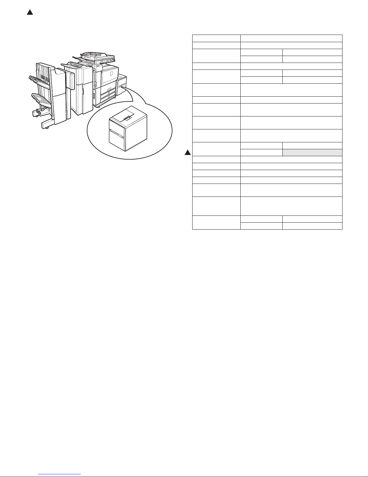
This model is a large capacity paper feed tray installed to the main unit.
It stores 3,500 sheets, eliminating troublesome paper supply.
AR-LC6
[2] SPECIFICATIONS
Transport speed Corresponds to 55 – 70 sheet/min.
Transport reference Center reference
Paper size AB series A4
Inch series 8.5" x 11"
Paper size setting Not provided.
Factory setting of
paper size
Kind/weight of
applicable paper
Paper capacity 3,500 sheets (80g/m
Remaining paper
detection
Paper feed system Front loading, paper feed from the upper
Tray lift time Up: max. 15sec
Power consumption Normal operation 26.4W or less
1
Power source 24V and 5V are supplied from the main unit
External dimensions 376 (W) x 545.5 (D) x 517.5 (H) mm
Occupying area 376 (W) x 545.5 (D) mm
Weight About 35kg or less
Paper feed system Paper pick-up by the take-up roller, Torque
Humidifying heater Power supplied from the main unit, ON/OF
Factory setting AB series A4
AB series A4
Inch series 8.5" x 11"
Normal paper 60 – 105g/m
Enable (Paper empty and 6 steps)
section
Down: max. 5sec
Lift up
limiter reverse rotation separation system
control by the main unit
Heater kit support
Inch series LT
2
(16 – 28lbs)
2
)
42W or less
AR-LC6 OUTLINE OF THE PRODUCT 1 - 1
Page 3
: Jan. 9 2004
1
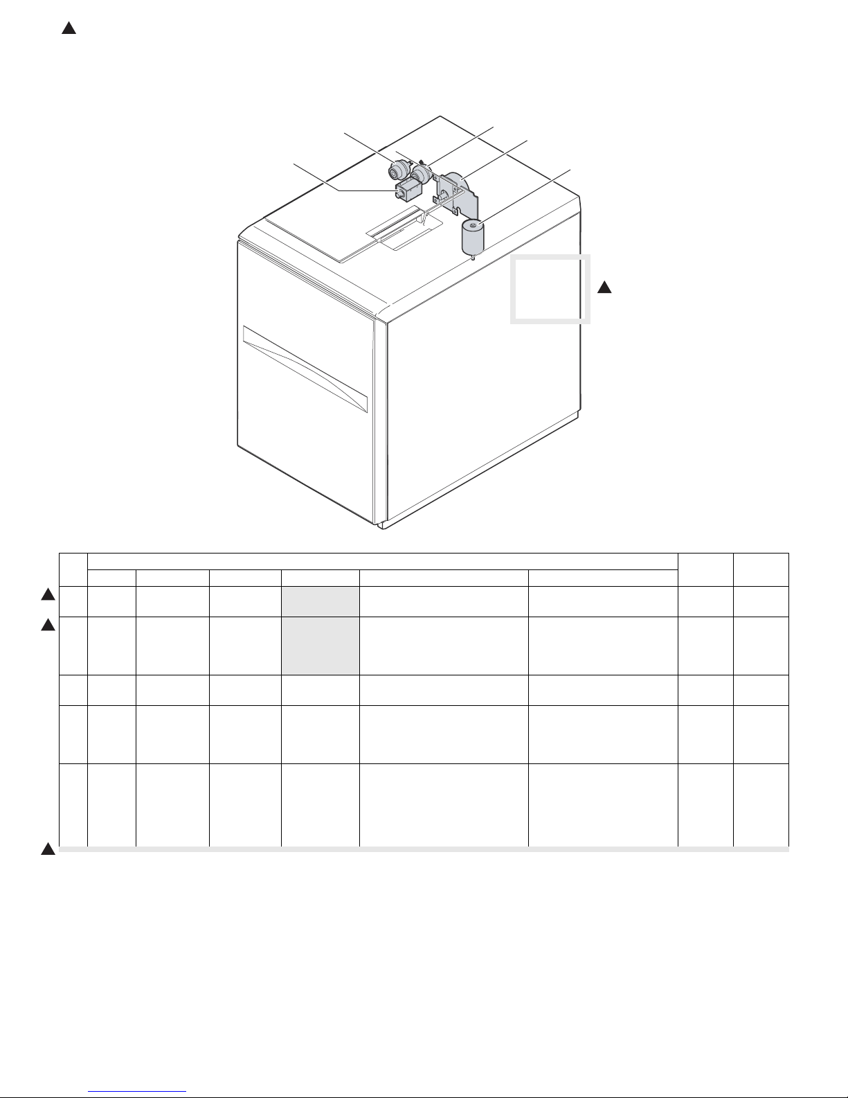
[3] INTERNAL CONSTRUCTION
1. Motor, clutch, solenoid
3
5
4
1
2
1
No.
Code Signal name Name Type Function/Operation Active condition
1 LTM LTM Transport
1
2 LLM LLM Lift motor
1
3 LTCL LTCL Transport
4 LPFCL LPFCL Paper feed
5 LPSL LPSL Paper feed
1
motor
clutch
clutch
solenoid
Parts
Brushless
motor
Brush motor Lifts the paper feed table. When the lower limit sensor
Drives the paper feed, and the
paper transport section.
Controls ON/OFF of the
transport roller.
Controls ON/OFF of the paper
feed roller.
Presses the paper pickup roller
onto paper.
When paper feed is started,
"H" level.
is ON, "H" level. When the
upper limit sensor is ON, "L"
level.
When paper feed is started,
"H" level. After starring
transport (pickup OFF), it is
turned OFF by the timer.
Turned OFF after starting
transport. Turned ON by the
timer.
∗ Lift-up – When paper
empty detection is made:
ON
MODEL NOTE
AR-LC6 INTERNAL CONSTRUCTION 3 - 1
Page 4
: Jan. 9 2004
1
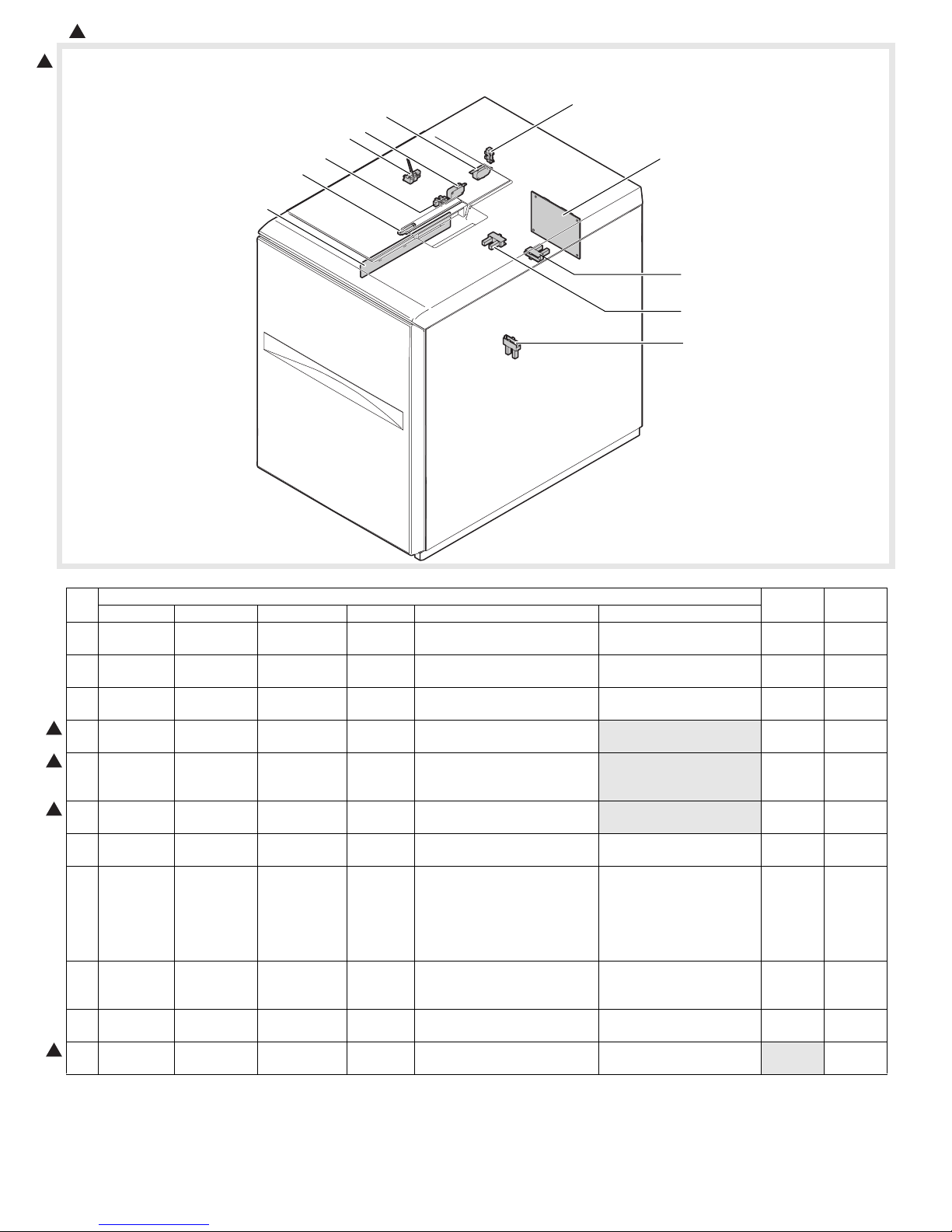
2. PWB, sensor, switch, heater
1
17
14
13
12
16
11
15
7
9
10
8
No.
1
1
1
1
Code Signal name Name Type Function/Operation Active condition
7 MAIN PWB – LCC main
PWB
8 LLD LLD Lower limit
sensor
9 LRE LRE Lift motor
encoder
10 LCD LCD Cassette
detection
11 LTOD LTOD The main unit
connection
sensor
12 LTD LTD Transport
sensor
13 LUD LUD Upper limit
sensor
14 LPED LPED Paper
presence/
empty sensor
15 LLSW LLSW Upper limit
switch
16 LOSW LOSW Upper open/
close switch
17 DH DH Thermal
heater
Parts
Controls and drives the LCC.
The lower limit of the tray is
detected.
The lift motor rotation is
detected.
The tray insertion is detected.
Detects connection to the main
unit.
Detects paper transport.
Detects the paper upper limit
position.
Detects paper presence/empty
on the paper tray.
Protects the paper feed unit
from breakage due to lifting the
tray too much.
Detects open/close of the
upper door.
Keeps temperature in the LCC
tray.
MODEL NOTE
When lifting up, "L" level.
Pulse signal
When inserted, "H" level.
When connected, "H" level.
"L" level at paper
remaining detection.
When "H" level (ON), the
lift-up motor stops.
When paper is detected,
"H."
∗ When lifting up, if "L"
with LRE 800 pulse, the
paper feed solenoid is
ON.
Japan
only
AR-LC6 INTERNAL CONSTRUCTION 3 - 2
Page 5
: Jan. 9 2004
1
[4] OPERATIONAL DESCRIPTIONS
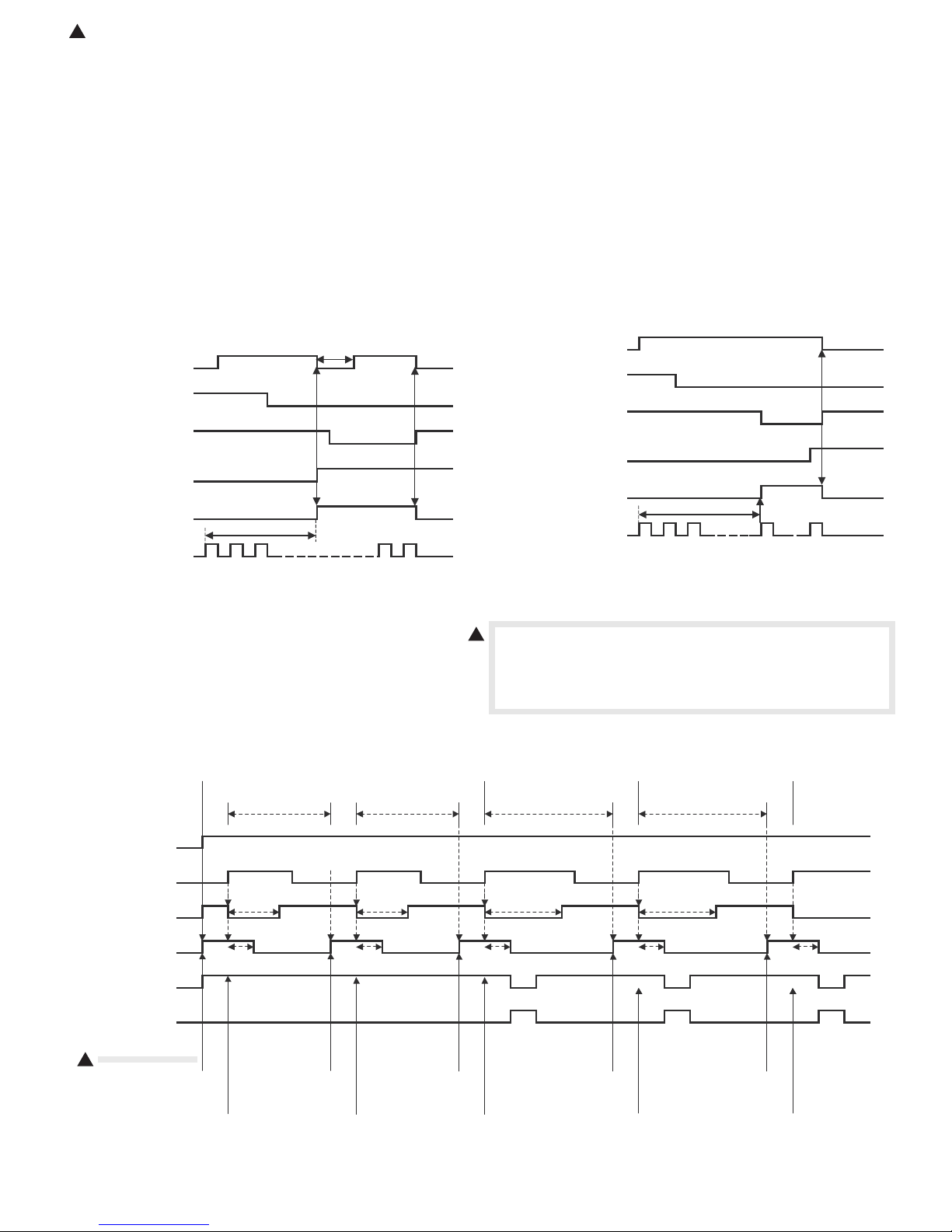
1. Lift operation
When the main unit is turned ON, if the tray is at the lower limit position
(lower limit sensor: LLD ON position), the lift motor is turned ON to lift
the tray.
When the paper presence/empty sensor (LPED) is turned ON within
800 pulses of the encoder signal from start of lifting up the tray, the lift
motor is turned OFF to stop the tray, and the paper feed solenoid is
turned ON to mode down the pickup roller. After that, the lift motor is
turned ON to lift the tray. The tray is stopped when the upper limit sensor (LUD) is turned ON.
If the paper presence/empty sensor (LPED) is not turned on within 800
pulses, the paper feed solenoid is turned ON with the lift motor ON to
move down the pickup roller. Then, the lift motor is turned ON again to
lift the tray. The lift motor is stopped at the upper limit sensor (LUD) ON
position, and the paper feed solenoid is turned OFF.
When the machine power is turned on, if the tray is on the paper feed
position, lifting is not performed.
When the tray is pulled out, it moves down by its own weight.
Lifting up operation (When LPED is turned ON within 800 pulses
of encoder.)
(Lift motor output)
LLM
LLD
(Lower limit sensor)
LUD
(Upper limit sensor)
LPED
(Paper empty detection)
LPSL
(Solenoid)
LRE
(Encoder signal)
Within 800 pulses
200 msec
2. Paper feed operation
When the tray is stationary at the paper feed position (upper limit sensor: LUD ON position) and there is paper on the tray, paper feed operation can be performed.
Paper feed operation is performed by the transport motor (LTM), the
transport clutch (LTCL), the paper feed clutch (LPFCL), and the paper
feed solenoid (LPSL) at the following timing.
LCC paper feed time chart
Paper feed start
Clearance-betweenpapers control timer
Clearance-between-
papers control timer
Lifting up operation (When LPED is not turned ON within 800
pulses of encoder.)
(Lift motor output)
(Lower limit sensor)
(Upper limit sensor)
(Paper empty detection)
(Encoder signal)
When the transport clutch (LTCL) is turned ON with the transport motor
1
LLM
LLD
LUD
LPED
LPSL
(Solenoid)
LRE
Within 800 pulses
(LTM) ON (rotating), the transport roller rotates. When the paper feed
clutch (LPFCL) is turned on under this state, the paper feed roller and
the take-up roller rotate. When the paper feed solenoid (LPSL) is
turned ON, the take-up roller is pushed down to press paper.
Resist stop Resist stop Resist stop
Clearance-betweenpapers control timer
Clearance-betweenpapers control timer
(Transport motor)
(Transport sensor)
(Paper feed solenoid)
(Paper feed clutch)
(Transport clutch)
synchronous signal)
1
LTM
LTD
LPSL
LPFCL
LTCL
TRC
(Main unit
Preliminary
paper feed start
First sheet
PIC drop timer PIC drop timer PIC drop timer PIC drop timer
Paper feed clutch
Preliminary paper
feed complete
Paper feed start
OFF timer
Preliminary
paper feed start
Second sheet
Preliminary paper
feed complete
Paper feed start
Paper feed clutch
OFF timer
Preliminary
paper feed start
Third sheet
Paper feed clutch
OFF timer
Preliminary
paper feed start
Fourth sheet
Preliminary paper
feed complete
Paper feed start
AR-LC6 OPERATIONAL DESCRIPTIONS 4 - 1
Paper feed clutch
OFF timer
Preliminary paper
feed complete
Paper feed clutch
OFF timer
Preliminary
paper feed start
Fifth sheet
Preliminary paper
feed complete
Page 6

: Jan. 9 2004
1
1 Paper feed roller clutch
2 Take-up roller
3 Paper feed roller
4 Paper feed solenoid
5 Transport clutch
6 Transport motor
7 Lift-up motor
1
5
1
4
1
6
3
7
2
3. Paper empty detection
When the tray lifts and stops at the paper feed position and during
paper feed operation, paper presence/empty is detected by the paper
presence/empty sensor (LPED).
When paper empty is detected in the tray during paper feeding, paper
feeding is stopped.
AR-LC6 OPERATIONAL DESCRIPTIONS 4 - 2
Page 7

[5] DISASSEMBLY, ASSEMBLY, MAINTENANCE
1. Maintenance system table
✕: Checking (clean, replace or adjust as required) ❍: Cleaning ▲: Replace ∆: Adjust ✩: Lubricate ❏: Position shift
AR-M550U/M550N
(PM: 250K)
AR-M620U/M620N
(PM: 300K)
Unit name No. Part name (Note)
Paper feed
separation
section
Transport
section
Drive
section
Others 7 Sensors ✕ ✕✕✕ ✕ ✕ ✕ ✕ ✕
(Note) Replacement reference: For replacement, refer to each paper feed port counter value.
1 Paper pickup roller/
Paper feed rollers
2 Torque limiter ✕ ✕✕✕ ✕ ✕ ✕ ✕ ✕
3 Transport rollers ✕❍❍❍❍❍❍❍❍
4 Transport paper guides ❍❍❍❍❍❍❍❍❍Gears (Specified position)
5 Gears ✕ ✩✩✩ ✩ ✩ ✩ ✩ ✩
6Belt ✕✕✕ ✕ ✕ ✕ ✕ ✕
Paper feed roller related section: 200K or 1 year
Torque limiter: 800K
calling
2. Maintenance parts replacement procedures
A. Paper feed roller
1) Pull the lever, and open the upper cover.
2) Remove the screw, and remove the sheet.
250K 500K 750K 1000K 1250K 1500K 1750K 2000K
When
300K 600K 900K 1200K 1500K 1800K 2100K 2400K
✕❍❍❍❍❍❍❍❍
4) Remove the screw, and remove the paper guide block.
5) Remove the pawl, and remove the reverse roller.
(Note)
Remark
3) Remove the pawl, and remove the pickup roller and the paper feed
roller.
AR-LC6 DISASSEMBLY, ASSEMBLY, MAINTENANCE 5 - 1
Page 8

3. Each unit removal
A. Paper feed unit
1) Pull out the tray.
B. Paper feed tray
1) Pull out the tray.
2) Remove the screws from the left and right rail sections.
2) Open the upper cover, and remove three screws.
3) Remove the upper cabinet.
4) Disconnect the connectors (2 positions).
3) Remove the tray unit from the rail.
C. Drive unit
1) Remove the screw, and remove the rear cover.
5) Remove the screw, and remove the paper feed unit.
AR-LC6 DISASSEMBLY, ASSEMBLY, MAINTENANCE 5 - 2
2) Remove the connectors (2 positions).
Page 9

3) Remove the screw, and remove the drive unit.
4. Major parts removal
A. Motor (Main)
1) Remove the screw, and remove the rear cover.
2) Disconnect the connector.
3) Remove the screw, and remove the motor.
4) Remove the screw, and remove the lift motor.
5) Remove the ring, and remove the pulley.
C. Clutch
1) Remove the paper feed unit. (Refer to "3. Each unit removal.")
2) Remove the screw, and remove the cover.
B. Lift motor
1) Remove the drive unit.
2) Remove the E-ring, and remove the parts.
3) Remove the screw, and remove the cover.
3) Remove the E-ring, and remove the parts.
AR-LC6 DISASSEMBLY, ASSEMBLY, MAINTENANCE 5 - 3
Page 10

: Jan. 9 2004
1
4) Disconnect the connector, and remove the screw.
5) Remove the frame.
6) Remove the connector, and the E-ring, and remove the paper feed
transport clutch.
1
D. Paper feed solenoid
1) Remove the paper feed unit.
2) Remove the cover.
3) Remove the screw, and remove the unit.
1
4) Disconnect the connector.
5) Remove the screw, and remove the solenoid.
E. Torque limiter
1) Remove the paper feed unit.
2) Remove the cover.
3) Remove the E-ring and the screw, and remove the parts.
4) Lift the shaft, and remove the torque limiter.
AR-LC6 DISASSEMBLY, ASSEMBLY, MAINTENANCE 5 - 4
Page 11

F. Transport roller
1) Remove the paper feed unit.
2) Remove the cover.
3) Remove the spring, and remove the screw.
4) Remove the plate cover, and remove the lever.
5) Remove the clutch.
6) Remove the screw and the E-ring, and remove the parts.
7) Remove the transport roller.
AR-LC6 DISASSEMBLY, ASSEMBLY, MAINTENANCE 5 - 5
Page 12

[6] ADJUSTMENT
Each adjustment item in the adjustment item list is indicated with its JOB number. Perform the adjustment procedures in the sequence of Job numbers
from the smallest to the greatest.
However, there is no need to perform all the adjustment items. Perform only the necessary adjustments according to the need.
Unnecessary adjustments can be omitted. Even in this case, however, the sequence from the smallest to the greatest JOB number must be observed.
If the above precaution should be neglected, the adjustment would not complete normally or a trouble may occur.
1. Setting item list
Job No. Adjustment item list
Simulation to
be used
ADJ 1 Print off-center adjustment 50-10
ADJ 2 Resist amount adjustment ADJ 2A Adjustment in the resist amount adjustment mode 51-2
ADJ 2B Adjustment in the print lead edge adjustment mode 50-5
2. Details
3) Select "0: TRAY SELECT" and press START key.
The display is shown as follows. Select "6: LCC" as the paper feed
tray, and press START key.
ADJ 1 Print off-center adjustment
1) Set the print off-center adjustment mode of SIM 50-10 by the key
operation of the machine. (Press the keys as shown below to enter
SIM 50-10.)
#/P C
∗
2) In SIM 50-10, the display is shown as follows. The print off-center
adjustment value can be set for each paper feed tray.
SIMULATION 50-10
PRINT OFF-CENTER ADJUSTMENT. SELECT 0-9, AND PRESS
START.
0.TRAY SELECT 1 1.COPY START
2.MAGNIFICATION 100
(ADJUSTMENT DATA)
3.TRAY1 50 4.TRAY2 50 5.TRAY3 50
6.TRAY4 50 7.BPT 50 8.LCC 50 9. ADU 50
Adjustment position Set value
Display
item
TRAY1 TRAY1 Print off center
TRAY2 TRAY2
(LCC left
side)
TRAY3 TRAY3
(LCC right
side)
TRAY4 TRAY4 Print off center
MFT Manual
paper feed
LCC Large
capacity tray
ADU Duplex Print off center
50 10
∗
Item description Default
adjustment position
Print off center
adjustment position
Print off center
adjustment position
adjustment position
Print off center
adjustment position
Print off center
50 0 to 99Shift by
adjustment position
2
Set
range
0.1mm for
set value 1
4) The display is shown as follows again. Select "8: LCC" and press
5) Then enter the adjustment value with 10-key.
6) Enter the adjustment value and press START key, and printing is
7) Check the printed self-print result, and repeat procedures 5) – 6)
SIMULATION 50-10
PRINT OFF-CENTER
START.
(FEED TRAY)
1.TRAY1 2.TRAY2 3.TRAY3 4.TRAY4
5.BPT 6.LCC
(ABOVE+10: DUPLEX MODE)
ADJUSTMENT. SELECT 1-16, AND PRESS
1
START key.
SIMULATION 50-10
PRINT OFF-CENTER ADJUSTMENT. SELECT 0-9, AND PRESS
START.
0.TRAY SELECT 1 1.COPY START
2.MAGNIFICATION 100
(ADJUSTMENT DATA)
3.TRAY1 50 4.TRAY2 50 5.TRAY3 50
6.TRAY4 50 7.BPT 50 8.LCC 50 9. ADU 50
2
(Default: 50, Adjustment range: 0 – 99)
• When the adjustment value is decreased by 1, the image is
shifted to the rear side by 0.1mm.
• When the adjustment value is increased by 1, the image is
shifted to the front side by 0.1mm.
SIMULATION 50-10
PRINT OFF-CENTER ADJUSTMENT. INPUT VALUE 0-99, AND
PRESS START.
8.LCC
50
started and the set value is stored.
SIMULATION 50-10
PRINT OFF-CENTER ADJUSTMENT. NOW COPYING.
until the value is in the range of 0 ± 3mm.
When the value is in the above range, press CA key to terminate
the simulation.
adjustment position
(ADU)
Print lead edge
(Rear side)
a
b
(Front side)
(Print back surface)
Adjust in the range
of the figure
(0 ± 3mm).
AR-LC6 ADJUSTMENT 6 - 1
Page 13

ADJ 2 Resist amount adjustment
ADJ 2A Adjustment in the resist amount
adjustment mode
ADJ 2A Adjustment in the print lead edge
adjustment mode
1) Set the print lead edge adjustment mode of SIM 50-5 by the key
operation of the machine.
1) Set the resist amount adjustment mode of SIM 51-02 by the key
operation of the machine.
#/P C
∗
2) In SIM 51-02, the display is shown as follows. The resist amount
adjustment value can be set for each paper feed tray.
SIMULATION 51-2
RESIST TIMING ADJUSTMENT. SELECT 0-14, AND PRESS START.
0.TRAY SELECT 1 1.PRINT START
2.TRAY1 50 3.TRAY2 50 4.TRAY3 50
5.TRAY4 50 6.BPT 50 7.LCC 50
8.ADU 50 9.SPF(TOP) 50 10.SPF(HIGH) 50
11.SPF(LOW) 50 12.SPF FEED(TOP) 50
13.SPF FEED(HIGH) 50 14.SPF FEED(LOW) 50
3) Select "0: TRAY SELECT" and press START key.
The display is shown as follows. Select "6: LCC" as the paper feed
tray, and press START key.
SIMULATION 51-2
RESIST TIMING ADJUSTMENT. SELECT 1-6, AND PRESS START.
(FEED TRAY)
1.TRAY1 2.TRAY2 3.TRAY3 4.TRAY4
5.BPT 6.LCC
(ABOVE+10: DUPLEX MODE)
4) The display is shown as follows again. Select "7: LCC" and press
START key.
SIMULATION 51-2
RESIST TIMING ADJUSTMENT. SELECT 0-14, AND PRESS START.
0.TRAY SELECT 1 1.PRINT START
2.TRAY1 50 3.TRAY2 50 4.TRAY3 50
5.TRAY4 50 6.BPT 50 7.LCC 50
8.ADU 50 9.SPF(TOP) 50 10.SPF(HIGH) 50
11.SPF(LOW) 50 12.SPF FEED(TOP) 50
13.SPF FEED(HIGH) 50 14.SPF FEED(LOW) 50
5) Then enter the adjustment value with 10-key.
(Default: 50, Adjustment range: 0 – 99)
• When the adjustment value is increased by 1, the resist amount
is increased by 1msec.
SIMULATION 51-2
RESIST TIMING ADJUSTMENT. INPUT VALUE 0-99, AND PRESS
START.
7.LCC
51 2
∗
1
1
1
50
#/P C
∗
2) In SIM 50-5, the display is shown as follows. The resist amount
adjustment value can be set for each paper feed tray.
SIMULATION 50-5
LEAD EDGE ADJUSTMENT. SELECT 0-12, AND PRESS START.
0.TRAY SELECT 1 1.PRINT START
(ADJUSTMENT DATA)2.RRCB 50
3.TRAY1 50 4.TRAY2 50 5.TRAY3 50
6.TRAY4 50 7.BPT 50 8.LCC 50 9.ADU 50
(VOID AREA SETTING) 10.DENA 50 11.DENB 30 12.FR VOID 30
3) Select "0: TRAY SELECT" and press START key.
The display is as shown below. Select "6: LCC" as the paper feed
tray and press START key.
SIMULATION 50-5
LEAD EDGE ADJUSTMENT. SELECT 1-6, AND PRESS START.
(FEED TRAY)
1.TRAY1 2.TRAY2 3.TRAY3 4.TRAY4
5.BPT 6.LCC
(ABOVE+10: DUPLEX MODE)
4) The display is as shown below again. Select "8: LCC" and press
START key.
SIMULATION 50-5
LEAD EDGE ADJUSTMENT. SELECT 0-12, AND PRESS START.
0.TRAY SELECT 1 1.PRINT START
(ADJUSTMENT DATA)2.RRCB 50
3.TRAY1 50 4.TRAY2 50 5.TRAY3 50
6.TRAY4 50 7.BPT 50 8.LCC 50 9.ADU 50
(VOID AREA SETTING) 10.DENA 50 11.DENB 30 12.FR VOID 30
5) Then, enter the adjustment value with 10-key.
(Default: 50, Adjustment range: 0 – 99)
• When the adjustment value is increased by 1, the resist amount
is increased by 1msec.
SIMULATION 50-5
LEAD EDGE ADJUSTMENT. INPUT VALUE 0-99, AND PRESS
START.
8.LCC
6) After entering the adjustment value, press START key, and printing is started and the set value is stored.
SIMULATION 50-5
LEAD EDGE ADJUSTMENT. NOW PRINTING.
50 5
∗
2
1
2
50
6) Enter the adjustment value and press START key, and printing is
started and the set value is stored.
SIMULATION 51-2
RESIST TIMING ADJUSTMENT. NOW PRINTING.
7) After completion of the adjustment, press [CA] key to terminate the
simulation mode.
7) After completion of the adjustment, press [CA] key to terminate the
simulation mode.
AR-LC6 ADJUSTMENT 6 - 2
Page 14

[7] TROUBLESHOOTING
1. General
When a trouble occurs in the machine or when the life of a consumable
part is nearly expired or when the life is expired, the machine detects
and displays it on the display section or notifies to the user or the serviceman by voice messages. This allows the user and the serviceman
to take the suitable action. In case of a trouble, this feature notifies the
occurrence of a trouble and stops the machine to minimize the damage.
2. Function and purpose
1) Securing safety. (The machine is stopped on detection of a trouble.)
2) The damage to the machine is minimized. (The machine is
stopped on detection of a trouble.)
3) By displaying the trouble content, the trouble position can be
quickly identified. (This allows to perform an accurate repair,
improving the repair efficiency.)
4) Preliminary warning of running out of consumable parts allows to
arrange for new parts in advance of running out. (This avoids stopping of the machine due to running out the a consumable part.)
3. Self diag message kinds
The self diag messages are classified as shown in the table below.
Class 1 User Warning of troubles which can be recovered by
the user. (Paper jam, consumable part life
expiration, etc.)
Service
man
Other —
Class 2 Warning Warning to the user, not a machine trouble
Trouble Warning of a machine trouble. The machine is
Other —
Warning of troubles which can be recovered
only by a serviceman. (Motor trouble,
maintenance, etc.)
(Preliminary warning of life expiration of a
consumable part, etc.)
stopped.
Monitors the machine
conditions.
Detects/analyzes
the content.
Trouble/Warning
Trouble
The machine is stopped.
The content is displayed.
Trouble/Warning
Trouble
Troubleshoot the cause.
Repair
Cancel the self-
diagnostic message with
the diagnostics
(test commands).
Reset
Warning
Warning
A consumable
part has reached
its lifetime.
YES
Replace or supply
the consumable part.
NO
4. Self diag operation
A. Self diag operation and related work flow
The machine always monitors its own state.
When the machine recognizes a trouble, it stops the operation and dis-
plays the trouble message.
A warning message is displayed when a consumable part life is nearly
expired or is expired.
When a warning message is displayed, the machine may be or may
not be stopped.
The trouble messages and the warning messages are displayed by the
LCD.
Some trouble messages are automatically cleared when the trouble is
repaired. Some other troubles must be cleared by a simulation.
Some warning messages of consumable parts are automatically
cleared when the trouble is repaired. Some other warning messages
must be cleared by a simulation.
Standby state
AR-LC6 TROUBLESHOOTING 7 - 1
Page 15

5. List
MAIN
No.
CODE
1 U6 09 Lift motor trouble LCC Tray lift-up Check connection.
2 20 Communication trouble LCC LCC communication Turn OFF/ON the power.
3 21 Transport motor trouble LCC Paper feed Check connection.
4 22 24V trouble LCC Power ON Check connection.
SUB
CODE
Title (Content) Section Operation mode Countermeasure (Remedy) Note
6. Details
Main Sub Title Lift motor trouble
U6 09 Display Message
Phenomenon Detail LCC lift motor operation
trouble. Tray lift-up trouble
Section LCC
Case 1 Cause Defective connection or
Check
and
Remedy
Case 2 Cause Motor lock, motor rpm
Check
and
Remedy
Case 3 Cause LC main PWB trouble, lift
Check
and
Remedy
Main Sub Title
U6 20 Display Message
Phenomenon Detail Communication error with
Case 1 Cause Defective connection or
Case 2 Cause LCC main PWB trouble,
Case 3 Cause Malfunction caused by
Communication trouble
Section LCC
Check
and
Remedy
Check
and
Remedy
Check
and
Remedy
disconnection of connector
and harness
Check the connector and
the harness in the motor
line. Connect the connector
properly. Replace the
harness.
abnormality, motor
overcurrent, LRE trouble,
intrusion of foreign material
Use SIM 4-2 to select LRE
and check the operation of
the single unit. Use SIM 4-3
to select LLM and check the
operation of the single unit.
Check for intrusion of any
foreign material in the drive
system.
motor trouble
Replace the LCC main PWB
or the lift motor.
LCC, communication line
test error after turning on the
power or canceling an
exclusive simulation.
disconnection of connector
and harness
Check the connector and
the harness of the
communication line.
Connect the connector
properly. Replace the
harness.
control PWB (PCU) trouble
Replace the LCC PWB.
Replace the control PWB
(PCU).
noises
Cancel by turning OFF/ON
the power.
Main Sub Title Transport motor trouble
U6 21 Display Message
Phenomenon Detail LCC transport motor
operation trouble
Section LCC
Case 1 Cause Defective connection or
Check
and
Remedy
Case 2 Cause Motor lock, motor rpm
Check
and
Remedy
Case 3 Cause LCC main PWB trouble,
Check
and
Remedy
Main Sub Title
U6 22 Display Message
Phenomenon Detail 24V supply for LCC is cut
Case 1 Cause Defective connection or
Case 2 Cause Power source fuse blown-off
Case 3 Cause Power source abnormality in
24V trouble
Section LCC
Check
and
Remedy
Check
and
Remedy
Check
and
Remedy
disconnection of connector
and harness
Check the connector and
the harness in the motor
line. Connect the connector
properly. Replace the
harness.
abnormality, motor
overcurrent, intrusion of
foreign material
Use SIM 4-3 to select LTM
and check the operation of
the single unit. Check for
intrusion of any foreign
material in the drive system.
transport motor trouble
Replace the LCC main PWB
or the transport motor.
off.
disconnection of connector
and harness
Check the connector and
the harness which connect
LCC and the main unit.
Connect the connector
properly. Replace the
harness.
Check for short circuit
between 24V and GND.
Check for pinched harness
and the LCC main PWB
trouble. Replace the fuse,
the harness, and the LCC
main PWB.
the main unit
Check 24V output on the
main unit side.
AR-LC6 TROUBLESHOOTING 7 - 2
Page 16

: Jan. 9 2004
1
[8] ELECTRICAL SECTION
1. Actual wiring chart
Main unit
Tray upper limit sensor
Tray paper sensor
LPED
<Paper feed unit>
GND2
/LPED
/LUD LUD
+5V
+5V
1 GND223
3
1
2
PHR-3
179228-3
1
SMR-03V-N
SMP-03V-NC
SMR-18V-N
SMP-18V-NC
346
9
814
91011
653
521772
8
Paper feed clutch
Paper feed solenoid
LTD
LPSL
LPFCL
+5VR2/LTD
1
PHR-3
SMR-02V-NSMP-02V-NC
3
2
1
221
2
1
1314151617
121110
12
1
14
2
1516171813
213
SMR-03V-N SMP-03V-NC
18
Paper transport sensor
GND2
3
Upper limit switch
Paper transport clutch
LLSWON
LTCL
NC
LTCL3
N.C.
332
1COM
2
1+24V
CZHR-03V-S
PS-187-3V
1
321
1
2
4
3
1
2
4
3
ELR-04NV ELP-04NV
Upper open/close switch
The main unit connection sensor
LTOD
LOSWON
+5V
LTOD
GND2
NC3
2
1COM
1
3
179228-3
FPS-187
112233
SMR-03V-N SMP-03V-NC
Cassette detection
LCDGND2
LLM+
+5V3
2
1 LCD
1
SMR-03V-N
ELR-03V
2
1
3
1
1
3
2
ELP-03V
SMP-03V-NC
Lift motor
LIFT
MOTOR
LLM-
2
321
3
2
LCC transport motor
LTM
LTM-T
+24V
GND1
LTM
LTM-CLK
5
4
2
3
PHR-5
1
11
ELP-02V ELR-02V
Heater
2
2
Main unit connection
4
4
ELP-12V
1136
12
5
1
12
5
ELP-15V
N.C.
AC-L(H)
F.G.
AC-N(H)
ELR-15V
ELR-12V
Earth
N.C.
TXD-LCC
3
275
3
275
RXD-LCC
/DTR-LCC
4
4
/DSR-LCC
RES-LCC
F.G.
8
6
8
+5V
GND2
+24V
GND1
/TRC-LCC
N.C.
N.C.
9
11
12
15
10
14
9
13
11
12
15
10
14
Input lift motor encoder
LRE
2
LRE
+5V1GND2
3
Lower limit sensor
LLD
LLD
+5V1GND2
2
3
1
SMR-02V-NSMP-02V-NC
2
11
2
231
SMP-03V-NC SMR-03V-N
231
321
321
SMP-03V-NC SMR-03V-N
CN-D
B10B-PHDSS-B
+24V(LOSW)
1
+24V(LOSW)
2
GND2
3
GND2
4
+24V(LLSW)
5
GND2
6
7
GND2
8
+24V
9
GND2
10
+24V
CN-C
B24B-PHDSS-B
+24V
1
2
LPFCL
+24V
3
4
LTCL
LPSL(+24V)
5
GND1
6
7
GND2
GND2
8
9
GND2
GND2
10
11
GND2
12
GND2
13
/LUD
14
/LPED
15
/LTD
LTOD
16
17
EXIN1
18
EXIN2
+5V
19
20
+5V
+5V
21
22
+5V
+5V
23
+5VR24
283GND2
1
CN-E
B14B-PHDSS-B
+5V
LCD
4
GND2
LLM 5
6
7
N.C.
N.C.
LLM(GND)11LTM-CLK
9
10
LTM
GND1 12
GND1 13
+24V(LOSW) 14
LTM-T
CN-A
B12B-PHDSS-B
+24V
GND1
N.C.
N.C.
+5V
GND2
TXD-LCC
RXD-LCC
/DTR-LCC
/DSR-LCC
RES-LCC
/TRC-LCC
CN-F
B11B-PH-K-S
MD
/RES
/RXD
LCC MAIN PWB
/TXD
N.C.
+5V(VD)
FVpp
RES
TXD
GND2(VD)
TEST
+5V
GND2
LTLSL
+24V
+5V
GND2
LRE
LLD
B8B-PH-K-S
CN-B
3164827
5
1
2
3
4
5
6
7
8
9
10
11
12
1
2
3
4
5
6
7
8
9
10
11
AR-LC6 ELECTRICAL SECTION 8 - 1
Page 17

: Jan. 9 2004
1
2. Block diagram
1
switch (LOSW)
Upper door open/close
24V
circuit
24V monitor
(LTM)
Transport motor
monitor circuit
Upper door detection
Upper limit switch (LLSW)
Upper limit detection
monitor circuit
Poly-switch 1.1A
Lift motor (LLM)
Current limit
circuit
Lift motor drive
circuit
(LLD)
(LUD)
Lower limit sensor
Upper limit sensor
Paper presence/empty
sensor (LPED)
Main unit connection
Paper exit sensor (LTD)
Sensor input circuit
sensor (LTOD)
Remaining quantity
Cassette sensor (LCD)
sensor (LRE)
(LPFCL)
Paper feed clutch
(LTCL)
Transport clutch
(LPSL)
Paper feed solenoid
Solenoid/clutch drive circuit
LCC
Communication
RXD-LCC
TXD-LCC
buffer circuit
DSR-LCC
DTR-LCC
RES-LCC
Arithmetic section
CPU (HD64F3644H)
Xtal
7.37MHz
GND25V24V
GND1
F.G.
On-board write circuit
Communication write circuit
LCC MAIN PWB
EEPROM
Power 12V circuit
24V 12V
Main unit
AR-LC6 ELECTRICAL SECTION 8 - 2
Page 18

LEAD-FREE SOLDER
The PWB’s of this model employs lead-free solder. The “LF” marks indicated on the PWB’s and the Service Manual mean “Lead-Free” solder.
The alphabet following the LF mark shows the kind of lead-free solder.
Example:
<Solder composition code of lead-free solder>
Solder composition
Sn-Ag-Cu
Sn-Ag-Bi
Sn-Ag-Bi-Cu
Sn-Zn-Bi
Sn-In-Ag-Bi
Sn-Cu-Ni
Sn-Ag-Sb
Bi-Sn-Ag-P
Bi-Sn-Ag
5mm
Lead-Free
Solder composition
code (Refer to the
table at the right.)
a
(1) NOTE FOR THE USE OF LEAD-FREE SOLDER THREAD
When repairing a lead-free solder PWB, use lead-free solder thread.
Never use conventional lead solder thread, which may cause a breakdown or an accident.
Since the melting point of lead-free solder thread is about 40°C higher than that of conventional lead solder thread, the use of the exclusive-use
soldering iron is recommendable.
Solder composition code
a
b
z
i
n
s
p
(2) NOTE FOR SOLDERING WORK
Since the melting point of lead-free solder is about 220°C, which is about 40°C higher than that of conventional lead solder, and its soldering capacity is
inferior to conventional one, it is apt to keep the soldering iron in contact with the PWB for longer time. This may cause land separation or may exceed
the heat-resistive temperature of components. Use enough care to separate the soldering iron from the PWB when completion of soldering is
confirmed.
Since lead-free solder includes a greater quantity of tin, the iron tip may corrode easily. Turn ON/OFF the soldering iron power frequently.
If different-kind solder remains on the soldering iron tip, it is melted together with lead-free solder. To avoid this, clean the soldering iron tip after
completion of soldering work.
If the soldering iron tip is discolored black during soldering work, clean and file the tip with steel wool or a fine filer.
Page 19

CAUTION FOR BATTERY REPLACEMENT
(Danish) ADVARSEL !
Lithiumbatteri – Eksplosionsfare ved fejlagtig håndtering.
(English) Caution !
Dispose of used batteries according to manufacturer’s instructions.
(Finnish) VAROITUS
Paristo voi räjähtää, jos se on virheellisesti asennettu.
Vaihda paristo ainoastaan laitevalmistajan suosittelemaan
(French) ATTENTION
Il y a danger d’explosion s’ il y a remplacement incorrect
de la batterie. Remplacer uniquement avec une batterie du
même type ou d’un type équivalent recommandé par
Mettre au rebut les batteries usagées conformément aux
(Swedish) VARNING
(German) Achtung
Explosionsgefahr bei Verwendung inkorrekter Batterien.
Als Ersatzbatterien dürfen nur Batterien vom gleichen Typ oder
vom Hersteller empfohlene Batterien verwendet werden.
Entsorgung der gebrauchten Batterien nur nach den vom
Udskiftning må kun ske med batteri
af samme fabrikat og type.
Levér det brugte batteri tilbage til leverandoren.
Danger of explosion if battery is incorrectly replaced.
Replace only with the same or equivalent type
recommended by the manufacturer.
tyyppiin. Hävitä käytetty paristo valmistajan ohjeiden
mukaisesti.
le constructeur.
instructions du fabricant.
Explosionsfara vid felaktigt batteribyte.
Använd samma batterityp eller en ekvivalent
typ som rekommenderas av apparattillverkaren.
Kassera använt batteri enligt fabrikantens
instruktion.
Hersteller angegebenen Anweisungen.
(For USA, CANADA)
(MANGANESS DIOXIDE) MEMORY BACK-UP BATTERY
THAT MUST BE DISPOSED OF PROPERLY. REMOVE THE
BATTERY FROM THE PRODUCT AND CONTACT YOUR
LOCAL ENVIRONMENTAL AGENCIES FOR INFORMATION
CE PRODUIT CONTIENT UNE PILE DE SAUVEGARDE DE
MÉMOIRE LITHIUM PRIMAIRE (DIOXYDE DE MANGANÈSE)
QUI DOIT ÊTRE TRAITÉE CORRECTEMENT. ENLEVEZ LA
PILE DU PRODUIT ET PRENEZ CONTACT AVEC VOTRE
INFORMATIONS SUR LES MÉTHODES DE RECYCLAGE ET
CAUTION FOR BATTERY DISPOSAL
"BATTERY DISPOSAL"
THIS PRODUCT CONTAINS A LITHIUM PRIMARY
ON RECYCLING AND DISPOSAL OPTIONS.
"TRAITEMENT DES PILES USAGÉES"
AGENCE ENVIRONNEMENTALE LOCALE POUR DES
DE TRAITEMENT.
Page 20

All rights reserved.
Printed in Japan.
No part of this publication may be reproduced,
stored in a retrieval system, or transmitted,
in any form or by any means,
electronic; mechanical; photocopying; recording or otherwise
without prior written permission of the publisher.
Trademark acknowledgements
• Microsoft® Windows® operating system is a trademark or copyright of Microsoft
Corporation in the U.S.A. and other countries.
®
• Windows
and Windows
U.S.A. and other countries.
• IBM and PC/AT are trademarks of International Business Machines Corporation.
• Acrobat
reserved. Adobe, the Adobe logo, Acrobat, and the Acrobat logo are trademarks of
Adobe Systems Incorporated.
• All other trademarks and copyrights are the property of their respective owners.
95, Windows® 98, Windows® Me, Windows NT® 4.0, Windows® 2000,
®
XP are trademarks or copyrights of Microsoft Corporation in the
®
Reader Copyright® 1987- 2002 Adobe Systems Incorporated. All rights
SHARP CORPORATION
Digital Document System Group
Products Quality Assurance Department
Yamatokoriyama, Nara 639-1186, Japan
2004 January Printed in Japan
 Loading...