

Page 1
SERVICE MANUAL
.
DIGITAL COPIER OPTION
LARGE-CAPACITY
PAPER FEED TRAY
MODEL AR-LC1
CONTENTS
[ 1 ] OUTLINE OF THE PRODUCT. . . . . . . . . . . . . . . . . . . . . . . . . . 1-1
[ 2 ] SPECIFICATIONS . . . . . . . . . . . . . . . . . . . . . . . . . . . . . . . . . . . 1-1
[ 3 ] UNPACKING AND INSTALLATION. . . . . . . . . . . . . . . . . . . . . . 3-1
[ 4 ] EXTERNAL VIEW AND INTERNAL CONSTRUCTION . . . . . . 4-1
[ 5 ] OPERATING PRINCIPLE . . . . . . . . . . . . . . . . . . . . . . . . . . . . . 5-1
[ 6 ] DISASSEMBLY AND REINSTALLATION . . . . . . . . . . . . . . . . . 6-1
[ 7 ] ADJUSTMENT . . . . . . . . . . . . . . . . . . . . . . . . . . . . . . . . . . . . . . 7-1
[ 8 ] MAINTENANCE. . . . . . . . . . . . . . . . . . . . . . . . . . . . . . . . . . . . . 8-1
[ 9 ] TROUBLESHOOTING. . . . . . . . . . . . . . . . . . . . . . . . . . . . . . . . 9-1
[10] WIRING DIAGRAM . . . . . . . . . . . . . . . . . . . . . . . . . . . . . . . . . 10-1
[11] EXPLANATION OF THE CIRCUITS . . . . . . . . . . . . . . . . . . . . 11-1
PARTS GUIDE
Parts marked with " " is important for maintaining the safety of the set. Be sure to replace these parts with specified
ones for maintaining the safety and performance of the set.
This document has been published to be used
SHARP CORPORATION
for after sales service only.
The contents are subject to change without notice
Page 2
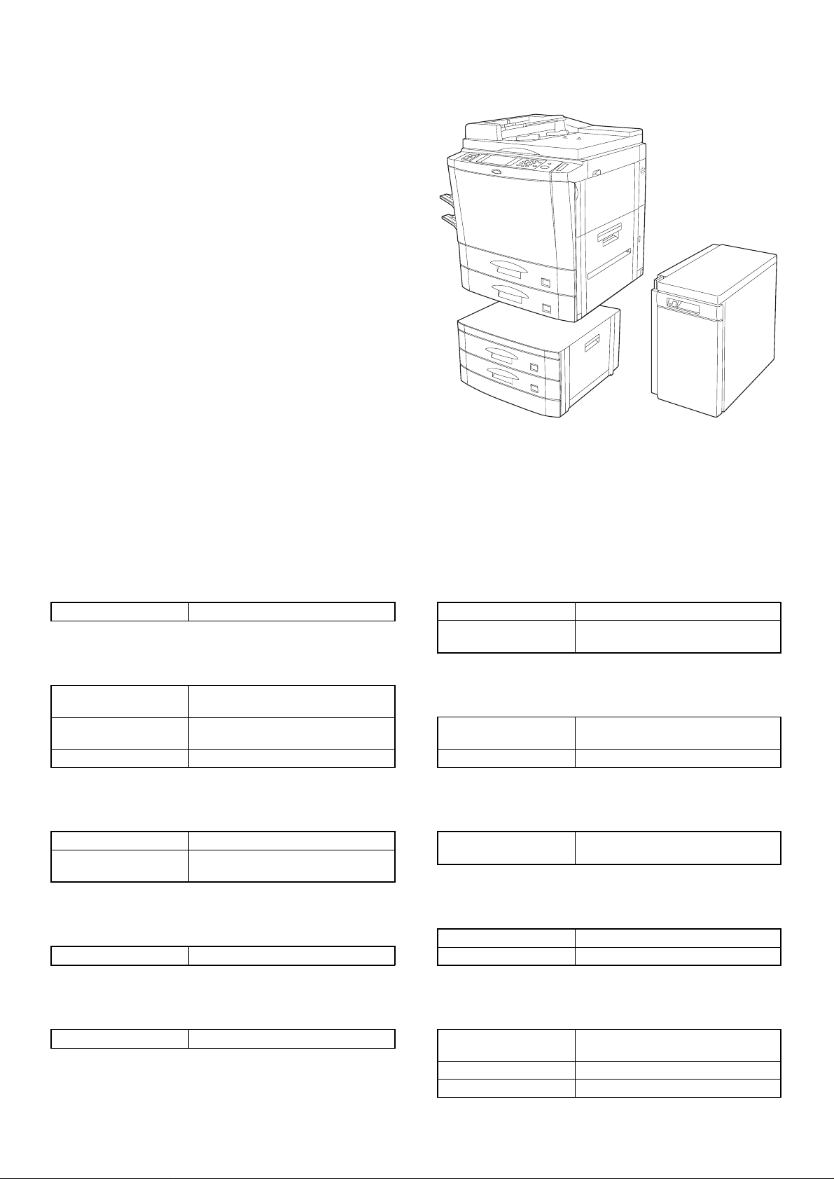
[1] OUTLINE OF THE PRODUCT
This paper feed unit stores about 3300 sheets of A4- or B5-size
paper to save the trouble of adding paper when a large amount of
copies is to be taken.
Note: If this large-capacity paper feed unit is to be installed, it is
required to install an optional single-stage paper feed desk
(AR-DE1) or special desk (AR-DD1).
AR-DE2 AR-LC1
[2] SPECIFICATIONS
(1) Paper feed capacity
Paper feed capacity 3300 sheets (64 g/m2 or equivalent)
(2) Amount detection
Paper amount detection Provided (5-stage sensors including
Detector 0% (empty),
Paper size detection None
(3) P ape r size
Paper size A4/B5
Paper weight 56
(4) Size switching
Switching to be performed by service personnel
empty detection)
∼ 25%, ∼ 50%, ∼ 75%,
∼ 100%
∼ 105 g/m
the copier’s paper feed section)
2
(14 ∼ 28 lbs) (Same as
(6) Dehumidifying heater
Yes/No Yes
ON/OFF switch ON/OFF by dehumidification heater
switch on the copier
(7) F actor y setting
Factory setting paper
size
Plate display A4
A4
(8) Power supply
Power supply supplied by the copier
(DC 5 V, DC 24 V)
(9) Power consumption
Max. power consumption about 17.6 W
At stand-by about 1.2 W
(5) Size detection
Size detection Setting by simulation
(10) External view
External dimensions 325 (wide) × 536 (deep) × 572 (high)
mm
Weight about 32 kg
Case color Frosty gray
1 – 1
Page 3
[3] UPACKING AND INSTALLATION
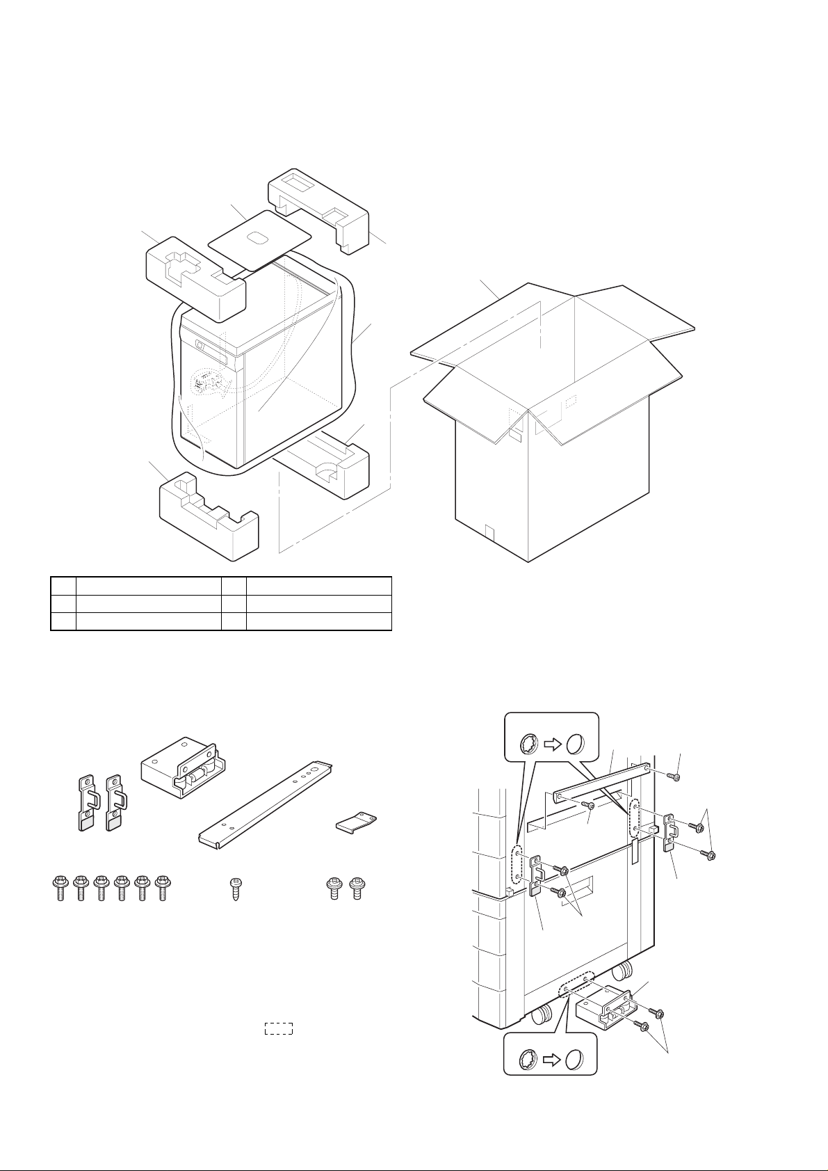
1. Unpacking
2
1
4
4
1
5
3
1 Upper cushion 2 Installation manual
3 LCC 4 Lower cushion
5 Packing case
2. Installation procedure
Parts included
Mounting plate
(1 pc.)
Upper mounting plates
(2 pcs.)
Screws A (6 pcs.)
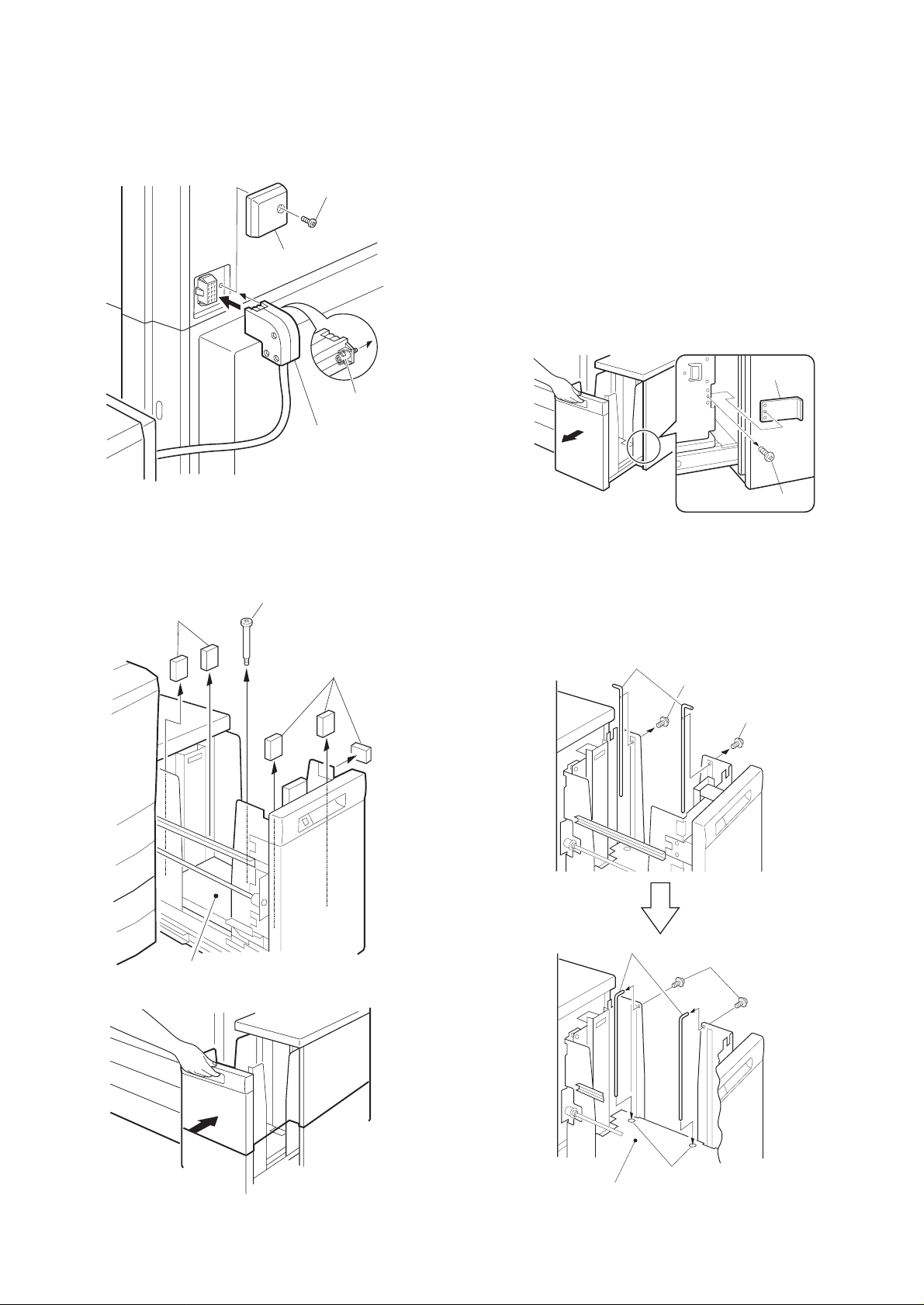
Remove the power cord from the copier and then
perform the following procedure.
1. M ou nt the upper mo un ting plate s and the mo un ting
plate.
Make 6 holes for mounting (indicated with ) on the copier and
lower part of the stand using a Phillips screwdriver, etc. and remove
burs using a flat-blade screwdriver, etc.Mount the upper mounting
plates using screws A (two for each plate).
Connecting plate
(1 pc.)
Screw B (1 pc.) Screws C (2 pcs.)
Securing plate
(1 pc.)
Then remove 2 screws from the LCC cover on the copier and remove
the LCC cover.
Hole for mounting
LCC cover
Screw
Screws A
Upper
mounting plate
Hole for mounting
Screw
Screws A
Upper
mounting plate
Mounting plate
Screws A
3 – 1
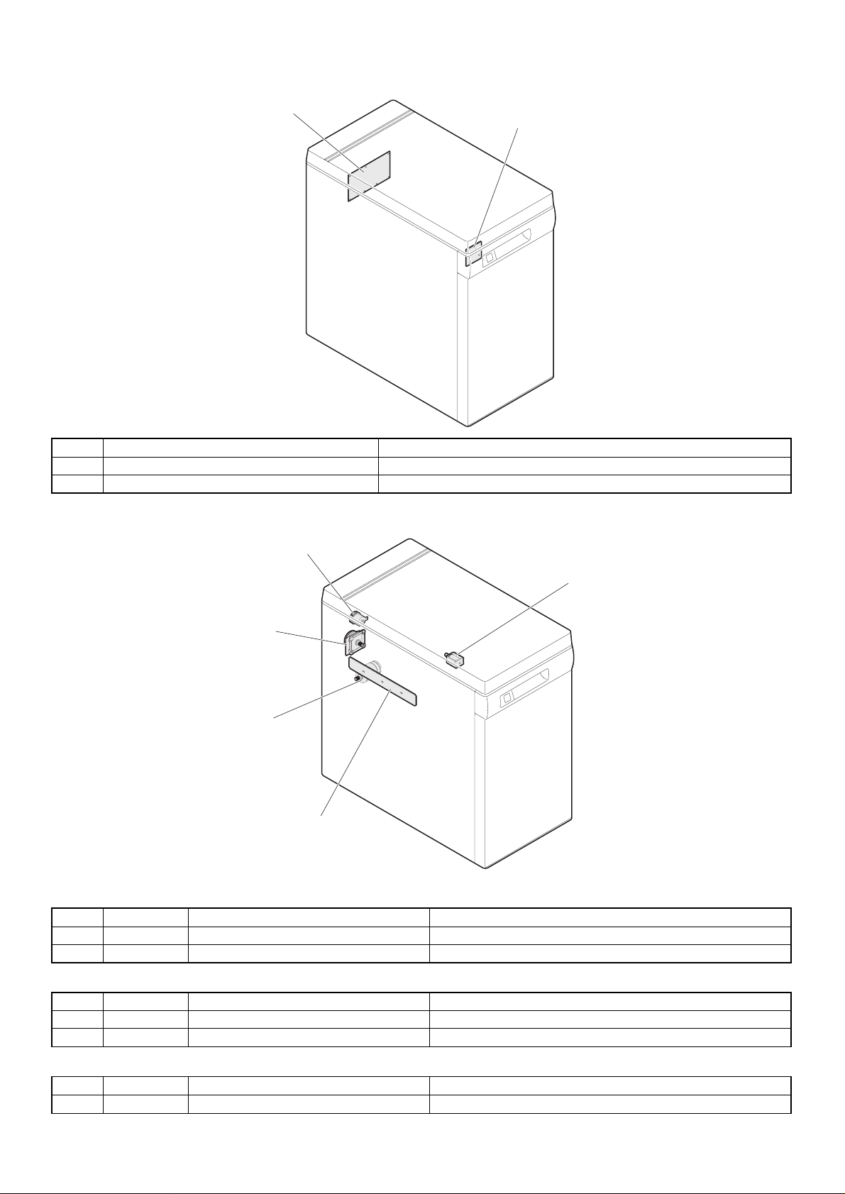
Page 4
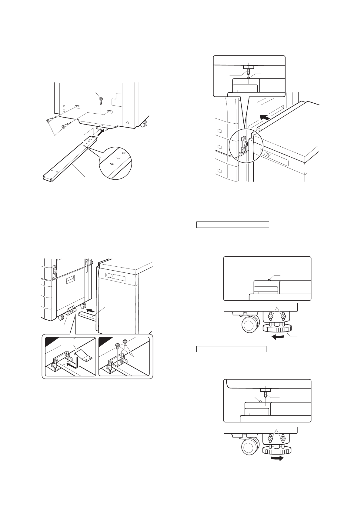
2. Mount the c onnecting plate to the large capacity tray.
Note: Before mounting the connecting plate to the large capacity
tray, be sure to remove the 2 step screws for securing the
bottom plate.
Fit the connecting plate to the lower part of the large capacity tray
and mount the plate to the position indicated with A using screw B.
Screw B
• If the axis is flush with the rib:
Push the large capacity tray toward the copier.
Top view
Axis
Rib
Step screws
‚a
‚`
‚a
‚`
Connecting plate
3. Fit the conn ecti ng p late of th e la rge cap a cit y tra y to
the mounting plate of th e stan d.
Insert the connecting plate into the mounting plate of the stand while
lifting the large capacity tray a little.
After insertion, move the large capacity tray away from the copier to
check that the tray is locked.While the tray is locked, mount the
securing plate using 2 screws C.
Connecting plate
• If the axis is not flush with the rib:
Loosen the 2 screws of the installation adjuster mounting plate located at the lower part of the large capacity tray and adjust as follows:
★ If the rib is to the right of the axis
Turn the knob clockwise to adjust.
After adjustment, tighten the 2 screws of the installation adjuster
mounting plate.
Top view
Axis
Rib
Screw
Mounting plate
Securing plate
1 2
Screws C
4. Check and adjust the height of the large capacity tray.
Move the large capacity tray toward the copier and adjust the tray
and check it so that the rib of the large capacity tray is flush with the
axis of the mounting plate which has been mounted to the copier as
shown in the figure.
★ If the rib is to the left of the axis
Turn the knob counterclockwise to adjust.
After adjustment, tighten the 2 screws of the installation adjuster
mounting plate.
3 – 2
Axis
Knob
Top view
Rib
Screw
Knob
Page 5
5. Connect the co n ne ct or of the large capacity tray.
Remove the connector cover securing screw for connection of the
large capacity tray relay harness connector and remove the connector cover.Then connect the large capacity tray relay harness connector to the connector of the copier and tighten the screw on the connector to secure the connector.
Securing screw
Connector cover
Screw
Connector
To use the large capacity tray without changing the paper size from
the factory default setting:
★Proceed to step 12 of this installation manual.
At this time, insert the power plug of the copier to an outlet and turn
the power switch to the "ON" position.
★Factory default setting: A4 size
The paper size can be switched only to the B5 size.
To use the large capacity tray after changing the paper size from the
factory default setting:
7. Remove the stopper from the paper tray.
Pull out gently the paper tray until it stops and remove the stopper
securing screw located on the lower part of the right side to remove
the stopper.
Then pull out again the paper tray until it stops.
Stopper
6. Remove the feed table securing screw and securing
materials.
Pull out gently the paper tray of the large capacity tray until it
stops.Remove the feed table securing screw and 5 securing materials
which secure the feed table of the large capacity tray.
Feed table securing screw
Securing materials
Securing materials
Feed table
Push back gently the paper tray to its original position.
Securing screw
8. Switch the rear end shaft.
Remove each rear end shaft securing screw (blue) which secures the
rear end shaft to the right side in the paper tray and remove the 2
rear end shafts.
Then fit the lower part of each removed rear end shaft to the mounting hole of the feed table of the paper tray and secure the upper part
to the position with B5 indication using a securing screw (blue).
Rear end shafts
Securing screw (blue)
Securing screw (blue)
Rear end shafts
Securing screw (blue)
3 – 3
Feed table
Mounting holes
Page 6
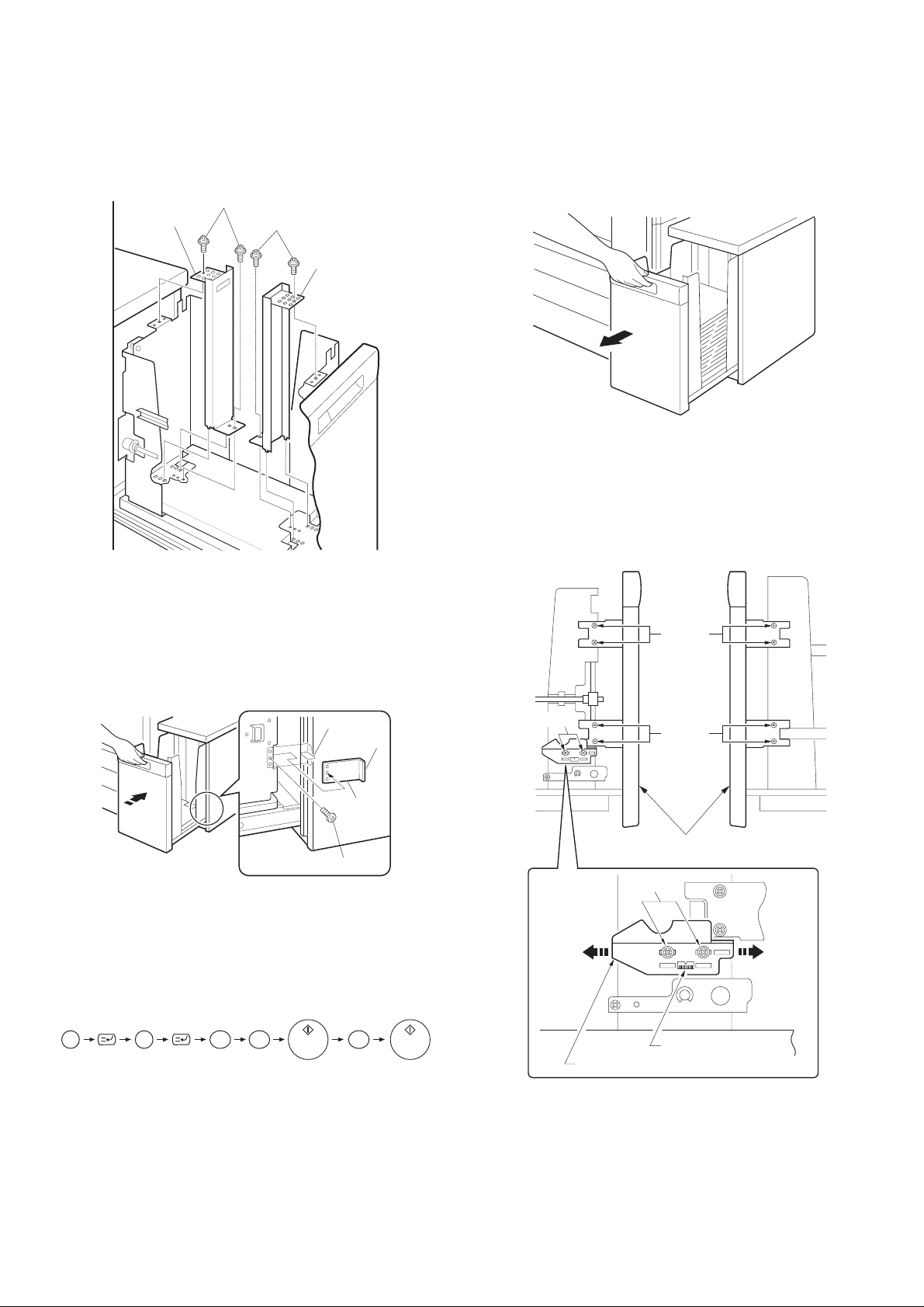
9. Switch the size of side plates F and R
Remove the screws which secure the upper and lower parts of side
plates F and R and remove side plates F and R.
Then fit the lower parts of side plates F and R to the position with B5
indication, position also the upper parts to the B5 size position, and
secure the plates using two screws (blue) for each plate.
Screws (blue)
Side plate R
Screws (blue)
Side plate F
12. Adjust the center position.
Since adjustment has been made at shipment, adjustment is basically
not needed. However, if the center should be displaced, adjust it
using the procedure below.
Make a copy. If the center is d isplaced as shown in Fig. 1 or Fig. 2,
pull out gently the paper tray until it stops.
Then, loosen the 2 screws at portion a which secure the tray lock
plate and the 8 screws at portion b (right and left sides) which secure
the tray cover unit to the frame and adjust the center position using
the procedure below.
10. Mount the stop pe r of the pa pe r tray.
Push in the paper tray a little, mount the stopper which has been
removed in step 9, and secure it using the screw. At this time, check
that the pawl of the stopper is caught by the stopper block of the large
capacity tray.
Then push back gently the paper tray to its original position.
Paper size switching is complete here.
Stopper block
Pawl
Stopper
Screw
Insert the power plug of the copier to an outlet, turn
the power switch to the "ON" position and then
perform the following procedure.
11. Register the pape r size.
• Register the paper size with the key operation of the copier.
Portion a
Direction A
Left side
Right side
Portion b
Portion b
Tray cover unit
Portion a
Direction B
P
2 6 2C
The LCC size selection window will be displayed in the message
display with the operation above.
Select the number of the size to be registered in the message display, enter the number using the keys on the operation panel and
press the OK key to register it.
Then turn the power switch to the "OFF" position and then to the
"ON" position again.
Scale (pitch in mm)
Tray lock plate
3 – 4
Page 7
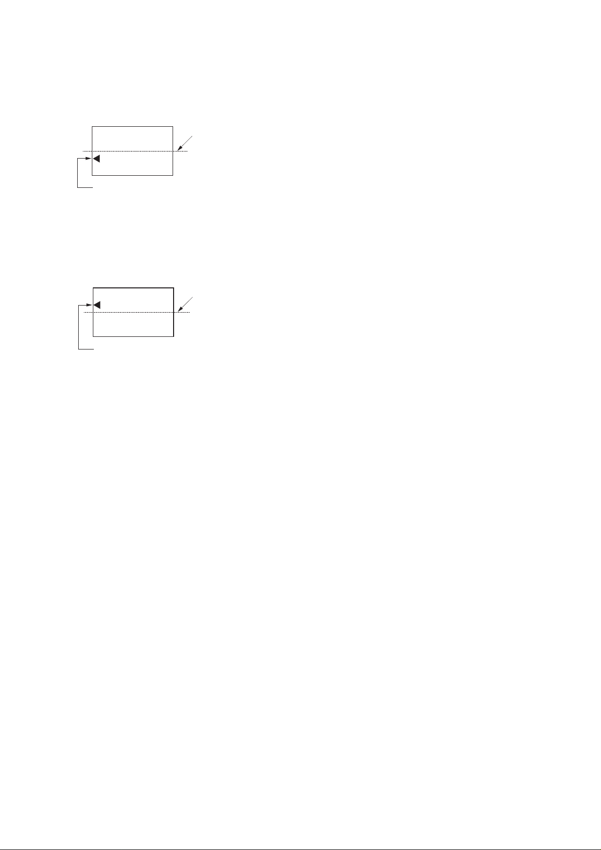
• In case of Fig. 1:
Move the tray lock plate in direction A by the lengt h of displacement,
tighten the 2 screws at portion a and then the 8 screws at portion b,
and make a copy again to check that the center is not displaced.
Fig. 1
Center line of paper
Center of image (first image)
• In case of Fig. 2:
Move the tray lock plate in direction B by the lengt h of displacement,
tighten the 2 screws at portion a and then the 8 screws at portion b,
and make a copy again to check that the center is not displaced.
Fig. 2
Center line of paper
Center of image (first image)
3 – 5
Page 8
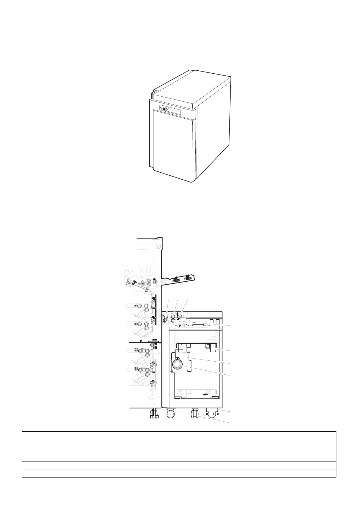
[4] EXTERNAL VIEW AND INTERNAL CONSTRUCTION
1. External view
1
1. Tray down button/lamp
The tray can be opened by pressing the button. Use this button when adding paper or paper jam occurs.
2. Main parts
123
4
5
6
7
8
9
No. Name No. Name
1 Transport roller 2 Paper feed roller
3 Hitching roller 4 Reversion roller
5 Tray 6 Lift-up unit
7 Encoder 8 Height adjustment unit
9 Caster
4 – 1
Page 9
PWB locatio n
1
No Name Function and operation
1 Control PWB Controlling LCC
2 Tray switch PWB Tray lifting switch
2
Motor, clutch, solenoid, motor
3 LPFC
4 LPFS
1 LPFM
2 LLM
5 HT
Motor
No. Symbol Name Function and operation
1 LPFM Paper feed and transport motor Driving paper feed and transport systems
2 LLM Lift-up motor Driving tray lifting up
Clutch and soleno id
No. Symbol Name Function and operation
3 LPFC Paper clutch Driving paper clutch
4 LPFS Pick-up solenoid Operating pick-up roller
Motor
No. Symbol Name Function and operation
5 HT Dehumidifying motor Dehumidifying paper and preventing condensation of dew.
4 – 2
Page 10

Sensor, d ete c t or lo c a tio n
2 LLSW
4 LUD
3 LPED
1 LPFD
7 LTOD
5 LRES
6 LDD
No. Symbol Name Function and operation
1 LPFD Transport detector Detecting paper discharge
2 LLSW Upper limit lock switch Detecting tray upper limit lock (Shutting off motor as a safety device.)
3 LPED Paper detector Detecting the presence of paper
4 LUD Upper limit detector Detecting tray upper limit position
5 LRES Encoder sensor Controlling lifting up
6 LDD Lower limit detector Detecting tray lower limit position
7 LTOD Copier connection detector Detecting connection to copier
4 – 3
Page 11

[5] OPERATING PRINCIPLE
Lifting (no paper, descending from top to bottom)
Descending starts
1. Lift-up operation
When the copier is powered up, the main circuit checks the detection
state of each sensor. If the upper limit detector (LUD) is OFF, the
lift-up motor is turned on to elevate the tray till the position which
allows paper feed (upper limit detector ON).
1,2
3
4
LLMD
LLMU
LDD
30msec
LUD
100msec
3. Paper feeding
When copying is started, the transport motor (LPFM) starts. Then, the
pick-up solenoid (LPFS) and paper feed clutch (LPFC) turn on. When
the solenoid is turned on, the paper hitching roller is lowered to
contact the paper.
When the clutch is turned on, both the paper feed roller and the
hitching roller rotate to start paper feeding. The paper is sent through
the transport sensor (D) to the copier.
4
2
1 Upper limit detector (LUD)
2 Paper detector (LPED)
3 Paper tray
4 Lower limit detector (LDD)
Lifting (no paper, lifting from bottom to top)
Elevation starts
LLMD
LLMU
LDD
About 100 msec
LUD
Reversion starts
5msec
30msec
2. Lift-down operation
If no paper is present after paper feed, the main circuit detects the
ON condition of the paper detector (LPED) and turns on the lift-up
motor to descend the tray till the position at which the lower limit
detector (LDD) turns on (the tray can be drawn out).
The tray switch PWB indication LED blinks while the tray is lifting or
descending.
1
3
1 Paper feed roller clutch (LPFC)
2 Paper hitching roller
3 Paper feed roller
4 Pick-up solenoid (LPFS)
Paper feed (Letter size, A4, B5)
Paper feed start signal reception
Job start signal reception
LPFM
LPFC
LPFS
3
2
4
Paper feed finish
signal transmission
Job END signal
reception
5 – 1
LPFD
Page 12

[6] DISASSEMBLY AND ASSEMBLY
1. Tr an sport section (Paper feed r o ller ) 2. Paper feed s ec tion
A. Paper feed unit
1)
2)
2)
3)
4)
2)
2)
6)
5)
2)
7)
5)
1)
1)
1)
2)
2)
1)
3)
1)
6 – 1
Page 13

B. Paper feed roller, take-up roller
2
C. Reverse roller
2)
1)
3)
2)
1)
3. Control PWB
1
rib
2)
3)
6)
4)
1)
5)
Note 1: When installing the paper feed roller, be careful of the install-
ing direction.
Note 2: When installing the paper feed clutch, check that the clutch
stopper is caught by the pawl.
…
1
6)
…
2
6 – 2
Page 14

4. Paper feed/transport motor
3)
2)
1)
5. Lift-up motor
2)
2)
1)
3)
2)
6 – 3
Page 15

[7] ADJUSTMENT
Lift-up motor (LLM) instal ling position adjustment
Install the motor so that the lift-up motor shaft comes to the center of
the insertion port of the lift-up motor installing plate shaft.
7 – 1
Page 16

[8] MAINTENANCE
Make sure to disconnect the phone line/communication cable from the copier before performing maintenance, because receiving the signal during
maintenance is dangerous.
1. Maintenance system table
: cleaning ★: lubrication ×: checking (cleaning, replacement or adjustment as required)
Unit name Name 80K 160K 240K 320K Remarks
Driving section Paper feed and transport gear
Lift-up gear ★★★★
Transport section Transport roller
Paper guide
Paper feed section Paper feed roller ××××Replacement period (80K or 2 years)
Reversion roller
Hitching roller
Torque limiter
2. Details of maintenance
A. Driving section
★★★★
××××Replacement period (80K or 2 years)
××××Replacement period (80K or 2 years)
××××
1
2
No. Name O peration Cycle Remarks
1 Paper feed and transport gear Lubrication 80K
2 Lift-up gear Lubrication 80K
8 – 1
Page 17

B. Paper feed and transport section
1
2
1
5
3
6
4
No. Name O peration Cycle Remarks
1 Transport roller Cleaning 80K
2 Paper feed guide Cleaning 80K
3 Paper feed roller Check
4 Reversion roller Check
5 Hitching roller Check
6 Torque limiter Check
80K Replacement period (80K or 2 years)
80K Replacement period (80K or 2 years)
80K Replacement period (80K or 2 years)
80K Replacement period (80K or 2 years)
8 – 2
Page 18

[9] TROUBLESHOOTING
If a trouble occurs, check the cause of the trouble using the following
flow charts.
N: No Y: Yes
1. Trouble code list
Trouble
code
U6 09 LCC lift motor trouble — LCC
20 LCC communication trouble — PCU
21 LCC transport motor trouble — LCC
22 LCC 24V power trouble — LCC
Trouble Remarks
2. Self-diagnostics
Trouble
code
U6 09 Content LCC lift motor trouble
Detail LCC lift motor trouble
Cause Sensor defective
LCC control PWB defective
Gear broken
Lift motor defective
Check and
remedy
Check sensor operation with SIM4-2.
Check lift motor operation with
SIM4-3.
20 Content LCC communication trouble
Detail Communication trouble with LCC
Error at communication line test when
power is turned on or leaving SIM.
Cause Connector: Defective connection of
harness or broken wire
LCC control PWB defective
Control PWB (PCU) defective
Control PWB (PCU) defective
Malfunction due to noise
Check and
remedy
Can be reset by turning on and off
power supply.
Check communication line connector
and harness.
21 Content LCC transport motor trouble
Detail LCC transport motor operation
trouble
Cause Motor lock
Motor speed error
Overcurrent to motor
LCC control PWB defective
Check and
remedy
Check transport motor operation with
SIM4-3.
22 Content LCC24V power supply error
Detail No power supply (24V) to LCC
Cause Connector: Harness connection
defective or broken wire
LCC control PWB defective
Power supply unit defective
Check and
remedy
Check power supply line connector
and harness.
Check for 24V at power supply unit
and LCC control PWB
Displayed on the control panel of the copier
Details of trouble
Trouble
detection
A. LCC does not operate
A
Is interface
harness properly
connected?
Y
+5V between
CN-B-7 and 8 of
control PWB?
Y
+24V between
CN-B9 and 10 of
control PWB?
Y
Ready state after
setting paper?
Y
N
N
N
N
DB
Connect properly.
Check and if necessary
replace harness.
Check and if necessary
replace harness.
F
9 – 1
Page 19

B. Lift motor error C. Transport motor error
B
Is fuse blown out?
Y
Is load on motor
shaft normal?
Y
Is upper limit
sw on paper feed
UN turned on?
Y
Is harness
connected properly?
N
N
Replace fuse.
Check mechanical load
and driving system, and
remove any foreign matter.
N
Lower tray until upper
limit switch turns off.
Connect harness properly.
N
Check harness and if
necessary replace.
C
Is load on motor
shaft normal?
Y
Is harness
connected properly?
Y
Does motor rotate
even slightly?
Y
Check mechanical load
N
and driving system, and
remove any foreign matter.
Connect harness properly.
N
Check and if necessary
replace harness.
N
Is voltage applied to
motor connector?
N
Y
Y
Does motor rotate
even slightly?
Y
Is motor
encoder sensor
output normal?
Y
N
Check and if necessary
N
D
Check and if necessary
replace control PWB.
Is voltage
applied to motor
connector?
Y
replace motor.
Is motor encoder
output normal?
N
Y
N
Check and if necessary
Check and if necessary
replace control PWB.
replace motor.
D. Sensor error
D
Check for
sensor mounting.
Is harness connected
properly?
Y
Replace control PWB.
N
Check mounting and if
necessary replace harness.
9 – 2
Page 20

E. Clutch and solenoid error
F. No paper is fed
Is each load
properly installed?
Conductivity
between coils of
each load?
Conductivity
between connectors
and terminals?
Replace control PWB.
G. Paper jam
G
Y
Is improper
paper used?
Y
E
N
Check mounting and if
necessary replace.
Y
N
Replace clutch or solenoid.
Y
N
Check and if necessary
replace harness.
Y
F
Is paper feed
rollers contaminated
with paper dust?
Y
Does roller rotate?
Y
Does pick-up
roller drop at paper
feeding?
Y
Does
pick-up roller
rotate in paper feed
direction at paper
Check mechanical load and
N
driving system. Remove any
foreign matter and clean.
N
C
N
E
N
E
feeding?
Y
N
Use specified paper.
N
Use specified
Is improper
paper used?
paper.
Y
Replace control PWB.
Foreign matter
in paper path?
Y
Is transfer
sensor normal?
Y
Sheets are fed
one by one?
Y
Replace
control PWB.
N
Remove foreign
matter.
N
D
N
roller contaminated
separation roller.
Is paper feed
unit properly
assembled?
Y
Is separation
with paper
dust?
Y
Replace
N
feed unit and if
N
Check paper
necessary
replace.
Clean.
9 – 3
Page 21

[10] WIRING DIAGRAM
Copier
LRE
LDD
TRAY SW
PWB
LIFT
MOTO
CN-11
1
2
3
CN-12
1
2
3
BL
BR
GY
BL
PL
GY
CN-13
GY
3
LB
2
BR
1
CN-14
RD
1
GY
2
PK
3
G8
GY GY
G4 G3
CN-RL
WH
CN-HT
WH
CN-DT 12pin
1
2
6
11
3
7
8
9
10
4
5
12
12
12
LHT
WH
WH
CN-A
BL
22 5V(LRE)
BR
24 LRE/
GY
26 GND2(LRE)
BL
21 5V(LDD)
PL
23 LDD
GY
25 GND2(LDD)
PK
28 LCD/
LB
27 LDSW/
BR
29 LLED
RD
3LLM+
PK
4LLM-
G1
LCC
CONTROL
PWB
83
BR
1
PLLBBR
2
4
TXD-LCC
RXD-LCC
DSR-LCC
CN-B
PKRDGY
3
5
DTR-LCC
RES-LCC
91051112467
BL
GY
75V8
9
10
24V
GND2
GND1
CN-A
CN-C
BL
95V(LUD)
BR
11LUD/
GY
13GND2(LUD)
BL
105V(LPED)
PL
12LPED/
GY
14GND2(LPED)
RD
124Vout
RD
224V(LLSW)
RD
524V(LPFC)
PK
6LPFC/
RD
724V(LPFS)
LB
8LPFS/
BL
155V(LPFD)
BR
17LPFD/
GY
19GND2(LPFD)
BL
165V(LTOD)
BR
18LTOD/
GY
20GND2(LTO)
BL
15V
BR
2RE
PL
3HU
LB
4HV
PK
5HW
GY
6GND1
PL
7U
LB
8V
PK
9W
1
2
3
4
5
6
7
8
9
10
11
12
CN-FT 3pin
1
2
3
CN-3CN-KT 12pin
3
LUD
2
1
CN-4
3
LPED
2
1
LLSW
CN-1 CN-2
CN-5
1
2
CN-6
1
2
CN-7
1
3
2
CN-8
1
2
3
LPFC
LPFS
LPFD
LTOD
CN-10
4
6
3
2
1
5
9
8
7
LPFM
10 – 1
Page 22

Control circuit
Block diagram
Copier
VCC
GND2
+24V
GND1
FG
RXDTXDDSRDTRRES-
Communication
buffer circuit
8MHz
Xtal
Power supply
monitoring unit
24V
Power supply
10 V circuit
10V
CPU(H8/3294)
Operation unit
Large-capacity tray control PWB
Large-capacity tray
24V
Lift motor drive
circuit
Solenoid drive
circuit
LED lighting circuit
Sensor input
circuit
Transfer motor
drive circuit
10V
Upper limit sw (LLSW)
Lift motor (LLM)
Paper amount detection
sensor (LRE)
Paper feed clutch (LPFC)
Paper feed solenoid (LPFS)
LLED
Cassette detection line (LCD)
Upper limit detection sensor (LUD)
Lower limit detection sensor (LDD)
Paper detection sensor (LPED)
Paper delivery detection sensor
(LPFD)
Copier connection sensor
Door open switch (LDSW)
Transfer motor (LPFM)
10 – 2
Page 23

[11] EXPLANATION OF THE CIRCUITS
1. Operation
(1) Communication buffer circuit
On the communication buffer circuit, signals are input and output by the transistor array TD62504 (IC02).
+5V
CN-B-1
CN-B-3
CN-B2
CN-B-4
TXD-LCC
DTR-LCC/
RXD-LCC/
DSR-LCC/
D01 D02 D07 D08
1SS133 x 4
D04 D05 D09 D10
1SS133 x 4
4.7K x 2
4.7K x 4
IC02C
314
TD62504F
IC02B
215
TD62504F
IC02E
12 5
TD62504F
IC02G
10 7
TD62504F
CPU(IC01)
2
P51/RXD
6
P46/CLK
1
P50/TXD
3
P52/SCK
Signal name Logic
DSR-LCC
DTR-LCC
TXD-LCC
RXD-LCC
H: Request for communication
L: No request for communication
H: Communication allowed
L: Communication inhibited
H: Normal
L: Start bit
H: Normal
L: Start bit
(2) Sensor input circuit
The sensor signals used by LCC are connected directly to the input port of the IC02. LPFD is provided with a static electricity n oise protective diode
which protects against static electricity from the paper transport section. The other sensors has the same circuit configuration as the LPED.
+5V
CPU
(IC01)
P21/A9
P22/A10
P20/A8
38 LPFD
37 LDD
39 LPED
1SS133
R79
10K
R80
10K
R78
10K
1SS133
D23
D24
R94
R95
22K
22K
C14 C15 C16
BR04
4.7K
1000P x 3
LPFD
LDD
LPED
CN-A-17
CN-A-23
CN-A-12
(3) Upper limit switc h
A limit switch is provided to protect the LCC If it fails to operate normally. If the tray exceeds the upper limit sensor (LUD) position, the switch is
turned on to shut off the power of the lift motor.
LCC control PWB
Upper limit switch
Lift motor
11 – 1
24V
24V(LLSW)
LLM+
LLM-
Lift motor
drive circuit
Page 24

(4) Solenoid and clutch drive circuit
The solenoids and clutches are driven by a Darlington transistor array TD62004AP with 7-circuit clamp diode. LPFS is turned on when the CPU’s
port output is at H. LPFC has the same circuit.
+24V
9A12004B
SOL
CPU(IC01)
P10/A0
48 LPFS
10.5K
LPFS/
CN-A-8
7.2K
3K
(5) Lift motor dr iv e c ir c uit
The tray height is adjusted according to the size of the paper mounted on the paper feed tray. The lift motor controls the rota tional direction
(CW/CCW) with the control signals (LLMU, LLMD) from the CPU. The circuit forms a bridge circuit with STA457C to allow the CW/CCW control.
A fuse (F01) is provided to protect the motor against shorting or overload.
IC04C
314
ULN2004A
IC04D
413
ULN2004A
CPU port
LLMU
LLMD
Lift motor
1-E4
1-E4
LLMD LLMU
Forward rotation (UP) L H
Forward rotation (DOWN) H L
OFF L L
R34 1K
R35 1K
D20
R36 1K
R37
D21
1SS133x2
IC07
7
2
STA457C
1
2
7
3
3
1
8
1K
8
4
4
6
9
9
6
5
51010
R38
R39
10K
10K
F01
1.25A/120V
T1.0A/250V
R40
3.9K
(1/4W)
C31
0.1uF
LLM+
LLM-
+24V(LLSW)
CN-A-3
CN-A-4
Suppose that both LLMD and LLMU become H level at the above circuit. If LLMU becomes H first, the STA457C pin 3 become H, IC04 pin 13
through IC07 pin 6 become H due to diode D20. Even if LLMU is at H and LLMD at H on the port, STA457C pin 1 is at L and pin 6 at H, thus no
conduction of STA457C is achieved.
(6) Transport motor drive circuit
+10V
R19
CN-C-3
CN-C-4
CN-C-5
CN-C-2
IC12A
2.7K
116
TD62504F
IC12B
215
TD62504F
IC12C
314
TD62504F
+5V
R15
R86
+5V
1.2K
1000P X4
+24V
R90
1K(1/4W)
R32
1K(1/4W)
D22
RD11EB
R87
R88
1.2K
C29
0.1U
1.2K
+24V
+5V
R85
2.2K
FR01
100(1/4W)
Q02
2SC1472K
C30
0.1U
2
3
4
BR15
2.2K X 3
R76
10K
D25
RD18FB1
HU
HV
HW
RE/
C17 C19
C18 C20
R14
2.2K
2.2K
IC05
1
2
4
3
5
6
8
+10V
10
C21
0.1U
RE
1-D2
+10V
IN1
IN2
IN3
IN4
IN5
IN6
VCC
VREF
UPC1246C
OUT1
OUT3
OUT5
OUT6
OUT4
OUT2
REVERSE
DIR
11
12
13
14
15
16
7
9
GND
1-D2
10K
R16
10K
R17
10K
R18
IC12D
R77
10K
413
TD62504F
PWM
1-D2
IC04E
12
5
ULN2004A
IC04F
11
6
ULN2004A
IC04G
710
ULN2004A
BR07
R20
R21
R22
R23
R24
R25
2
2.2K
3
2.2K
4
2.2K
1K x3
BR08
4
680
3
680
2
680
C22 C23 C24
1K x3
0.1U X3
C26
0.1U
IC06
2
IA1
8
IB1
9
IC1
1
VCC
3
OA
7
OB
10
OC
5
GND
12
GND
11
IC2
6
IB2
4
IA2
SLA6012
+10V
+5V
R27
2.4K
R28
200
R29
R26
360
0.22
/1W
8
IC09A
3
+
1
2
LM393
4
C27
0.1U
The motor drive circuit is composed of IC05 motor ICs (IC12, IC04 and IC06). When the PWM signal output from the CPU made at H level, the
transistor inside the IC06 turns on t o supply current to the motor to start the motor. As the mot or is started, hole signals (Hu, Hv, Hw) inside the
motor switch the input of IC05, while the output switches the transistor inside IC06. The motor thus starts rotating under non-control state.
When the motor rotates, the speed signal (RE) is output from the motor. The signal is taken into the CPU. If the motor speed is slow, the RWM
signal On duty is increased to increase the speed; if the motor speed is high, the PWM signal On duty is decreased to maintain the required speed.
As the current flowing to the mot or becomes large, the input voltage at the m inus side of the IC09 rises. If the voltage exceeds the plus-side input
voltage, output voltage at IC09 becomes at L level, leading in the PWM signal to turn off the transistor of IC07 so that the current to the motor is cut
off. (setting: 3A).
11 – 2
C34
0.1U
+
C25
100U/35V
D17 D18 D19
+24V
ISR124-400 X3
U
CN-C-7
V
CN-C-8
W
CN-C-9
Page 25

(7) 24V power detection line
The line monitors 24V power. If the 24V power fed from the copier is not 24V, the level becomes L and the 24V power error is sent to the copier.
24V
R04
22K
55
P36/D6
R05
4.7K
(8) Cassette detection line
This line has the same circuit as each sensor. When the LCC cassette door is opened, the CPU becomes at H level; when the door is closed, the
line is connected to GND and the CPU becomes at L level.
5V
P26/A14
33
R84
10K
(9) LED lighting circ uit
This is the LED lighting circuit for the cassette door switch.
5V
BR04
2.2K
P27/A15
32
IC12E
TD62504F
BR04
4.7K
1000p
R03
220(1/4W)
Drawer connector
LED
When the CPU outputs the L signal, the LED comes on.
11 – 3
Page 26

D
C
B
A
CN-A-6
CN-A-30
12345678
LCD2
+24V
CN-A-8
LPFS/
LPFC/
16
15
ULN2004A
IC04A
10K
R93
R91
22K
R04
22K
ULN2004A
IC04B
1
2
LPFC
LPFC
LPFSLPFS
10K
R89
R92
4.7K
R05
4.7K
2-C2
LLMD
LLMU
2-C2
LLMD
LLMU
+5V
R63
R66
R65
R64
R62
CN-A-17
CN-A-23
LDD
LPFD
1SS133
D23
R95
22K
22K
R94
R79
R61
R59
R58
R57
R56
R55
LCD2
/24VM
DTR-LCCDTR-LCC
YOBI
10K
R80
4.7K X 11
N.C
N.C
N.C
N.C
N.C
N.C
N.C
LRELRE
N.C
N.C
N.C
N.C
D24
C15
C14
10K
49
P30/D0
50
P31/D1
51
P32/D2
52
P33/D3
53
P34/D4
54
P35/D5
55
P36/D6
56
P37/D7
57
P40//ADTRG//IRG
58
P41//IRQ1
59
P42//IRQ0
60
P43//RD
61
P44//WR
62
P45//AS
63
P46/CLK
64
P47//WAIT
IC01
H8/3294 FP-64A
1SS133
LPED
1000P X2
+5V
R78
4.7K X 4
R54
R74
R73
R72
LPFC
N.C
N.C
LLMU
LPFS
N.C
LLMD
N.C
48
40
47
VSS
P10/A0
P17/A741P16/A642P15/A543P14/A444P13/A345P12/A246P11/A1
P50/TXD
P51/RXD2P52/SCK3/RES4/NMI5VCC6/STBY7VSS8XTAL9EXTAL10MD111MD012AVSS13P70/AN014P71/AN1
1
/NMI
VCC
XTAL
/STBY
TXD-LCC
RES-LCC
DSR-LCC
RXD-LCC
CN-A-12
LUD
65432
10K
R81
LPFD
LDD
LPED
37
39
P21/A938P20/A8
P66/FTOB/TMRI1
P65/FTID/TMCI1
P64/FTIC/TMO0
P63/FTIB/TMRI0
P60/FTCI/TMCI0
MD1
MD0
EXTAL
LUD
AVSS
CN-A-11
LDSW
N.C
R41
CN-A-27
LDSW
LTOD
BR04
4.7K X 5
10K
10K
R82
R83
LCD1
LTOD
33
P26/A14
P25/A1334P24/A1235P23/A1136P22/A10
P27/A15
P67/TMO1
P62/FTIA
P61/FTOA
AVCC
P77/AN7
P76/AN6
P75/AN5
P74/AN4
P73/AN3
P72/AN2
16
15
N.C
N.C
R42
R43
4.7K X 3
VCC
CN-A-18
CN-A-28
LCD1
1000P X5
C16
C13
C12C10 C11
10K
10K
R84
2-C2
PWM/
DIR
LLED/
32
31
VCC
R52
30
N.C
R51
29
N.C
R75
N.C
28
PWM/
27
DIR
26
RE
25
R50
24
N.C
R49
23
SW2
22
VCC
R48
21
N.C
R47
SW1-4
20
SW1-3
19
R46
R45
18
SW1-2
SW1-1
17
R44
4.7K X 10
CN-A-29
LLED
R03
220(1/4W)
+5V
IC12E
TD62504F
512
R02
2.2K
+5V
2-B2
2-B2
RE
+5V
CN-A-15
CN-A-21
220(1/4W)
220(1/4W)
R96
R97
+5V
2 1
11
IC12F
6
10
IC12G
TD62504F
TD62504F
7
R
4.7K
+5V
=
R
3
C09
6785243
+5V
O314O215O116O413O710O512O6
I33I22I11I44I77I55I6
IC02
6785243
+5V
+5V
D01 D02 D03
+5V
1SS133x6
DTR-LCC/
TXD-LCC
COUGAR - LCC MAIN PWB
RES-LCC/
CN-B-1
CN-B-3
CN-B-5
D
C35
C05
LRE/
0.1U
11
6
CN-A-24
0.1U
10K
R01
C08
47U
+
C07
BR02
4.7KX7
9
NC
GND
TD62504F
8
BR01
4.7KX7
1SS133x2
D07 D08
0.1U
0.1U
D05
D04 D06
DSR-LCC/
RXD-LCC/
CN-B-2
CN-B-4
C
+5V
CN-C-1
CN-A-13
CN-A-19
CN-A-5
CN-A-7
CN-A-9
CN-A-10
CN-A-16
X1 8.00MHz
D10
D09
1SS133x2
+24V
CN-A-1
+24V
+24OUT
+24V
CN-A-22
+5V
+5V
0.1U
C02
47U/35V
+
C01
GND1
+5V
CN-A-20
CN-A-14
CN-A-26
CN-A-25
CN-C-6
0.1U
C04
+
47U/35V
C03
GND2
+24V(LLSW)
8 7 6 5 4
GND2
+24V(LLSW)
CN-A-2
CN-B-6
A
CN-B-10
+5V
CN-B-7
CN-B-8
+24V
GND1
CN-B-09
B
11 – 4
Page 27

D
C
B
A
12345678
CN-C-7
CN-C-8
CN-C-9
V
U
W
9
2.2K
R22
1OA3OB7
VCC
ULN2004A
TD62504F
10
OC
1K x3
IC04F
611
IC12B
215
D17 D18 D19
GND5GND12IC211IB26IA2
432
BR08
680
R23
ULN2004A
TD62504F
ISR124-400 X3
4
680
680
R24
R25
10
IC04G
7
IC12C
314
0.1U
C34
1
IC09A
LM393
8
4
+
+10V
SLA6012
+5V
C22 C23 C24
0.1U X3
1K x3
ULN2004A
TD62504F
-
3
2
C27
0.1U
2.2K
2.2K
1.2K
R28
IC05
R87
R29
200
R26
C26
10K
10K
10K
R16
R17
R18
16
OUT111OUT312OUT513OUT614OUT415OUT2
IN11IN22IN34IN43IN55IN66VCC8VREF
234
BR15
1.2K
R88
1.2K
360
/1W
0.22
0.1U
IC12D
TD62504F
413
R77
10K
1-D2
PWM
7
9
1-D2
GND
DIR
REVERSE
UPC1246C
10
0.1U
C21
+10V
RE
1-D2
2.2K X 3
R76
10K
R85
2.2K
+5V
+24V
R27
2.4K
R15
R14
+5V
+5V
R86
FR01
F01
IC04C
1-E4
100(1/4W)
+24V(LLSW)
1.25A/120V
T1.0A/250V
IC07
STA457C
7
2
R36 1K
R34 1K
ULN2004A
314
LLMU
Q02
2SC1472K
LLM+
7
2
CN-A-3
3
116
IC04D
+10V
0.1uF
C31
R40
3.9K
9944883
10
5
6
1K
R37
R35 1K
413
LLMD
D25
C30
0.1U
C29
0.1U
2 1
CN-A-4
LLM-
(1/4W)
R39
10K
R38
10K
10
5
1SS133x2
D21
D20
ULN2004A
7
IC09B
1-E4
+24V
RD18FB1
LM393
+
-
5
6
IC12
IC04
9
8
9
N.C
8
3
+24V
C25
100U/35V
+
IA12IB18IC1
IC06
234
BR07
2.2K
2.2K
R20
R21
IC04E
512
IC12A
116
+10V
R19
2.7K
COUGAR - LCC MAIN PWB
D
D22
R32
R90
1K(1/4W)
+24V
1000P X4
C18 C20
C17 C19
HV
HU
RE/
HW
CN-C-3
CN-C-4
CN-C-5
CN-C-2
C
B
RD11EB
1K(1/4W)
8 7 6 5 4
A
11 – 5
Page 28

D
C
B
A
12345678
2 1
1
2
3
4
5
6
7
8
9
3
5V
RE/HUHVHWGND2
CN-C (B9B-EH-A)
UVW
RXD-LCC
DSR-LCC
GND2
GND2
123456789
TXD-LCC
DTR-LCC
RES-LCC5V24V
24V(LLSW)
LLM-
LPFC/
LPFS/
65
2
1
87
34
GND1
10
5V(LPED)
LPED/
109
12
11
GND2(LPED)
5V(LTOD)
LTOD/
1615
13 14
17 18
GND2(LTOD)
5V(LRE)
LRE/
GND2(LRE)
LCD1/
LCD2/
2019
2423
2827
21 22
25 26
29 30
24V(OUT)
LLM+
24V(LPFC)
24V(LPFS)
5V(LUD)
LUD/
GND2(LUD)
CN-A (B30B-PHDSS) CN-B (B10B-PHDSS)
5V(LPFD)
COUGAR - LCC MAIN PWB
D
LPFD/
C
GND2(LPFD)
5V(LDD)
LDD/
GND2(LDD)
LDSW/
11 – 6
LLED/
8 7 6 5 4
B
A
Page 29

COPYRIGHT 1998 BY SHARP CORPORATION
All rights reserved.
Printed in Japan.
No part of t his publication may be reproduc ed,
stored in a r etrieval system, or transmitted,
in any form or by any means,
electro nic, mechanica l, photocopyi ng, recording, o r otherwise,
without pr ior written permis sion of the publi sher.
SHARP CORPORATION
Printing & Reprographic Systems Group
Quality & R e lia bility Control Ce nter
Yamatokoriyama, Nara 639-1186, Japan
1998 May Printed in Japan
 Loading...