

Page 1

SERVICE MANUAL
.
DIGITAL COPIER
OPTIONS
AR-DD1
AR-DE1
AR-DD1
AR-CS1
MODEL AR-CS1
CONTENTS
[ 1 ] PRODUCT OUTLINE. . . . . . . . . . . . . . . . . . . . . . . . . . . . . . . . . 1-1
[ 2 ] SPECIFICATIONS . . . . . . . . . . . . . . . . . . . . . . . . . . . . . . . . . . . 1-1
[ 3 ] UNPACKING AND INSTALLATION. . . . . . . . . . . . . . . . . . . . . . 1-1
[ 4 ] EXTERNAL VIEW AND INTERNAL STRUCTURE. . . . . . . . . . 4-1
AR-DE1
Desk
1-step paper
feed desk
Paper feed
module
[ 5 ] DISASSEMBLY AND ASSEMBLY. . . . . . . . . . . . . . . . . . . . . . . 5-1
[ 6 ] ADJUSTMENTS. . . . . . . . . . . . . . . . . . . . . . . . . . . . . . . . . . . . . 6-1
[ 7 ] MAINTENANCE. . . . . . . . . . . . . . . . . . . . . . . . . . . . . . . . . . . . . 7-1
[ 8 ] TROUBLESHOOTING. . . . . . . . . . . . . . . . . . . . . . . . . . . . . . . . 8-1
[ 9 ] ELECTRICAL SECTION . . . . . . . . . . . . . . . . . . . . . . . . . . . . . . 9-1
Parts marked with " " is important for maintaining the safety of the set. Be sure to replace these parts with specified
ones for maintaining the safety and performance of the set.
This document has been published to be used
SHARP CORPORATION
for after sales service only.
The contents are subject to change without notice
Page 2

CAUTION FOR BATTERY REPLACEMENT
(Danish) ADVARSEL !
Lithiumbatteri – Eksplosionsfare ved fejlagtig håndtering.
(English) Caution !
Danger of explosion if battery is incorrectly replaced.
Dispose of used batteries according to manufacturer’s instructions.
(Finnish) VAROITUS
Paristo voi räjähtää, jos se on virheellisesti asennettu.
Vaihda paristo ainoastaan laitevalmistajan suosittelemaan
tyyppiin. Hävitä käytetty paristo valmistajan ohjeiden
(French) ATTENTION
Il y a danger d’explosion s’ il y a remplacement incorrect
de la batterie. Remplacer uniquement avec une batterie du
même type ou d’un type équivalent recommandé par
Mettre au rebut les batteries usagées conformément aux
(Swedish) VARNING
Udskiftning må kun ske med batteri
af samme fabrikat og type.
Levér det brugte batteri tilbage til leverandoren.
Replace only with the same or equivalent type
recommended by the manufacturer.
mukaisesti.
le constructeur.
instructions du fabricant.
Explosionsfara vid felaktigt batteribyte.
Använd samma batterityp eller en ekvivalent
typ som rekommenderas av apparattillverkaren.
Kassera använt batteri enligt fabrikantens
instruktion.
Page 3
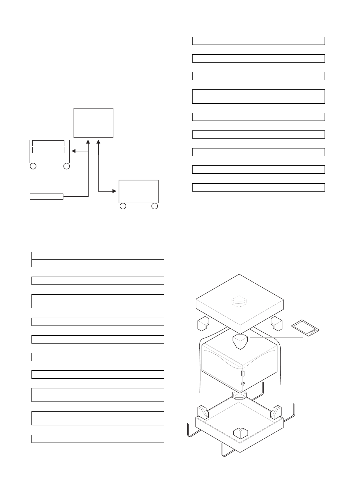
[1] PRODUCT OUTLINE
The AR-DD1 is the exclusive-use desk for a copier body, which
stores copy paper.
The AR-DD1 (1-step paper feed desk) serve as the paper feed unit
which also serves as a desk for a copier.
The AR-DE1 is composed of the paper feed/transport section, the
lift-up section, and the paper feed tray section. By installing the ARDE1 to a copier, the additional paper feed tray is available as shown
below;
Installation of the paper feed module (AR-CS1) to the AR-DE1 adds
one more paper feed tray.
Copier body
[1-step paper feed desk]
AR-DE1
550-sheet tray
(Slot for AR-CS1)
AR-CS1
Paper feed module
AR-CS1 (Option)
550-sheet tray
11. Tray falling/rising time (AR-DE1):
Within 8 sec (at min. number of set paper)
12. Power:
5V and 24V supplied from the copier.
13. Weight:
AR-DE1 25kg (excluding paper)
14. Drive form:
Drive motor (The DC brushless motor and the control PWB
are included in the desk.)
15. Operation control system:
Controlled by the communication command from the copier.
16. Paper transport path:
Paper entry from the lower section of the copier.
17. Dehumidifying heater:
Provided (power consumption 14W
18. External dimensions:
600(W) x 604(D) × 403(H)mm
19. Power consumption:
24W (MAX) 4.5W (Ready condition)
[2] SPECIFICATIONS
1. Model:
AR-DD1 Desk
AR-DE1 Desk-type paper feed unit
2. No. of steps of paper feed:
AR-DE1 1-step (2-step with the AR-CS1 installed)
3. Paper size:
A3/B4/A4R/B5R/A4/B5
× 17"/8.5" × 13"/8.5" × 11"/8.5" × 11R)
(11"
4. Paper weight:
56 ∼ 105g/m
5. Paper capacity:
Each tray 500 sheets (Paper weight 80g/m2)
6. Paper set:
Center reference, tray size when shipping A3
7. Paper supply system:
Front loading system. Supplied at the top.
8. Paper feed system:
Paper pickup system by the takeup roller, torque limiter
separation system
9. Paper transport speed:
170mm/s ∼ 306mm/s (The speed depends on the
communication command from the copier body.)
10. Paper feed speed:
33 sheets/min
2
[3] UNPACKING AND
INSTALLATION
1. UNPACKING
For unpacking, refer to the figure below.
A. AR-DD1
1 – 1
Page 4
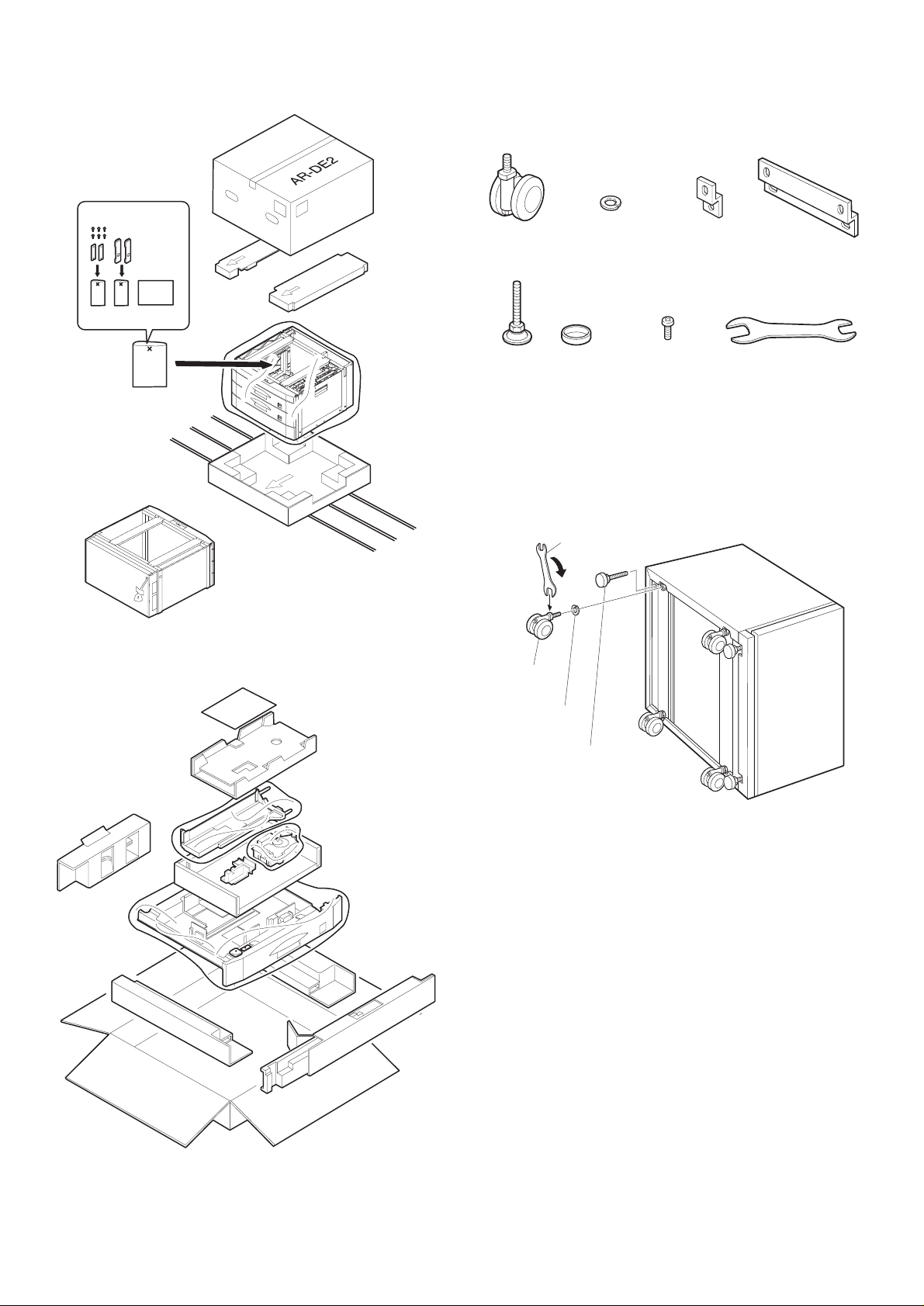
B. AR-DE1
2. Installing procedure
A. AR-DD1
C. AR-CS1
Caster
(4 pcs.)
Adjuster / with cover
(3 pcs.)
Spring washer
(4 pcs.)
Connection plate
fixing screw
(8 pcs.)
Connection
plate small
(2 pcs.)
Connection
plate large
(1 pc.)
Caster fixing wrench
(1 pc.)
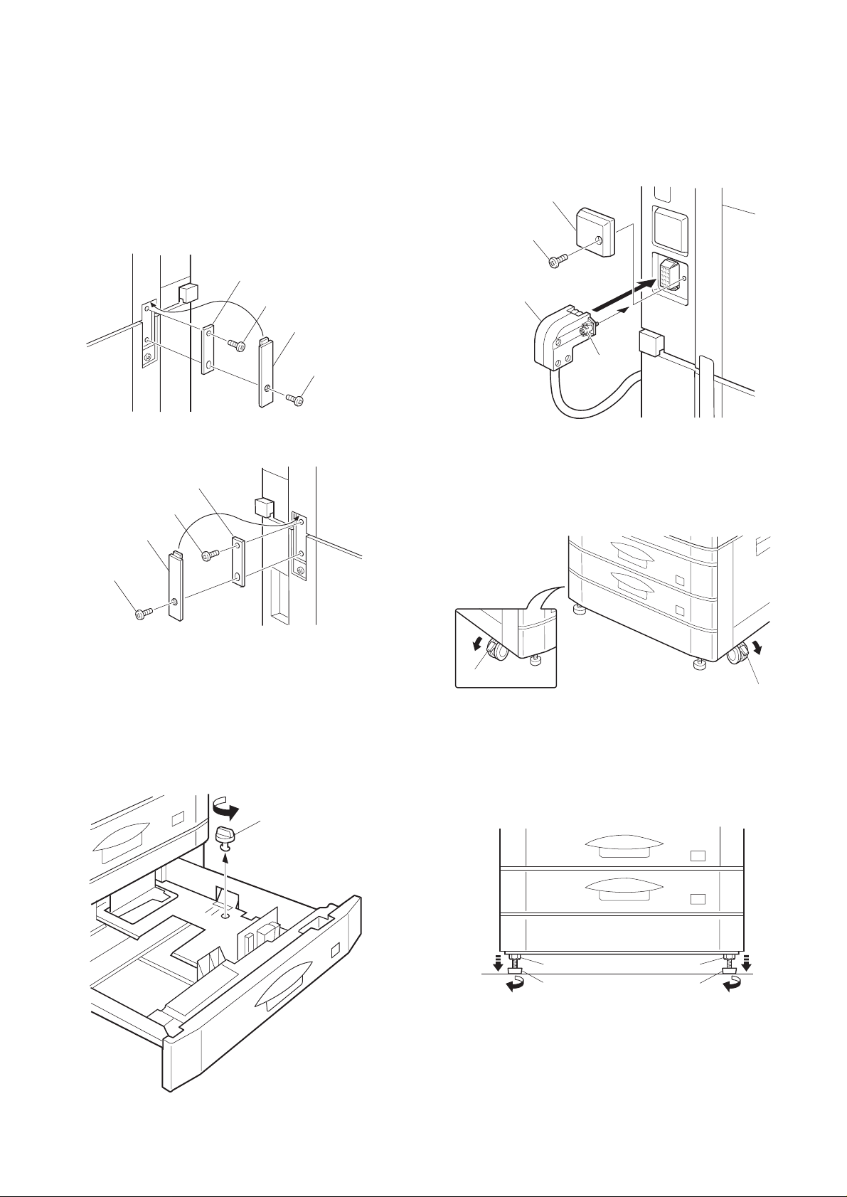
1. Install the ca st er an d th e ad ju st er.
Put the desk as shown below, and install the casters (4 pcs.) and
adjusters (4 pcs.).
When installing the casters, use the caster fixing wrench packed
together.
Caster fixing wrench
Caster
Spring washer
Adjuster / with cover
3 – 1
Page 5
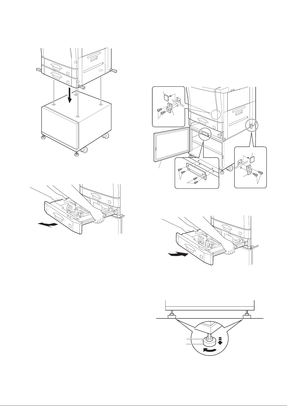
2. Put the copier on the des k.
Hold the four knobs of the copier, fit the four tabs of the copier w ith
the four holes of the desk, and place the copier on the desk.
4. Connect the copier and the desk.
Open the desk front cover.
Install the connecting plate large to the connecting plate installing
position with the four connecting plate fixing screws to fix the copier
and the desk.
Then cut off the notch sections (at right and left of t he copier) in the
connecting plate installing section.
Install the connecting plate small to the position shown in the figure
below with the connecting plate fixing screws (2 pcs. for each) to fix
the copier and the desk.
Notch
Connecting
Fixing
plate small
screw
Notch
3. Remove th e lower tray of the copier.
Remove the lower tray of the copier as shown.
Front cover
Connecting
Fixing
screw
Connecting
plate large
plate small
Fixing screw
5. Install the lo w er tra y of the cop ie r.
Install the lower tray of the copier as shown.
6. Fix the desk to th e floo r.
Turn the nut of the ad juster which is in the lower section of the desk
with a wrench or nippers in the direction of arrow, and adjust and fix
the desk on the floor.
3 – 2
Nut
Adjuster
Page 6
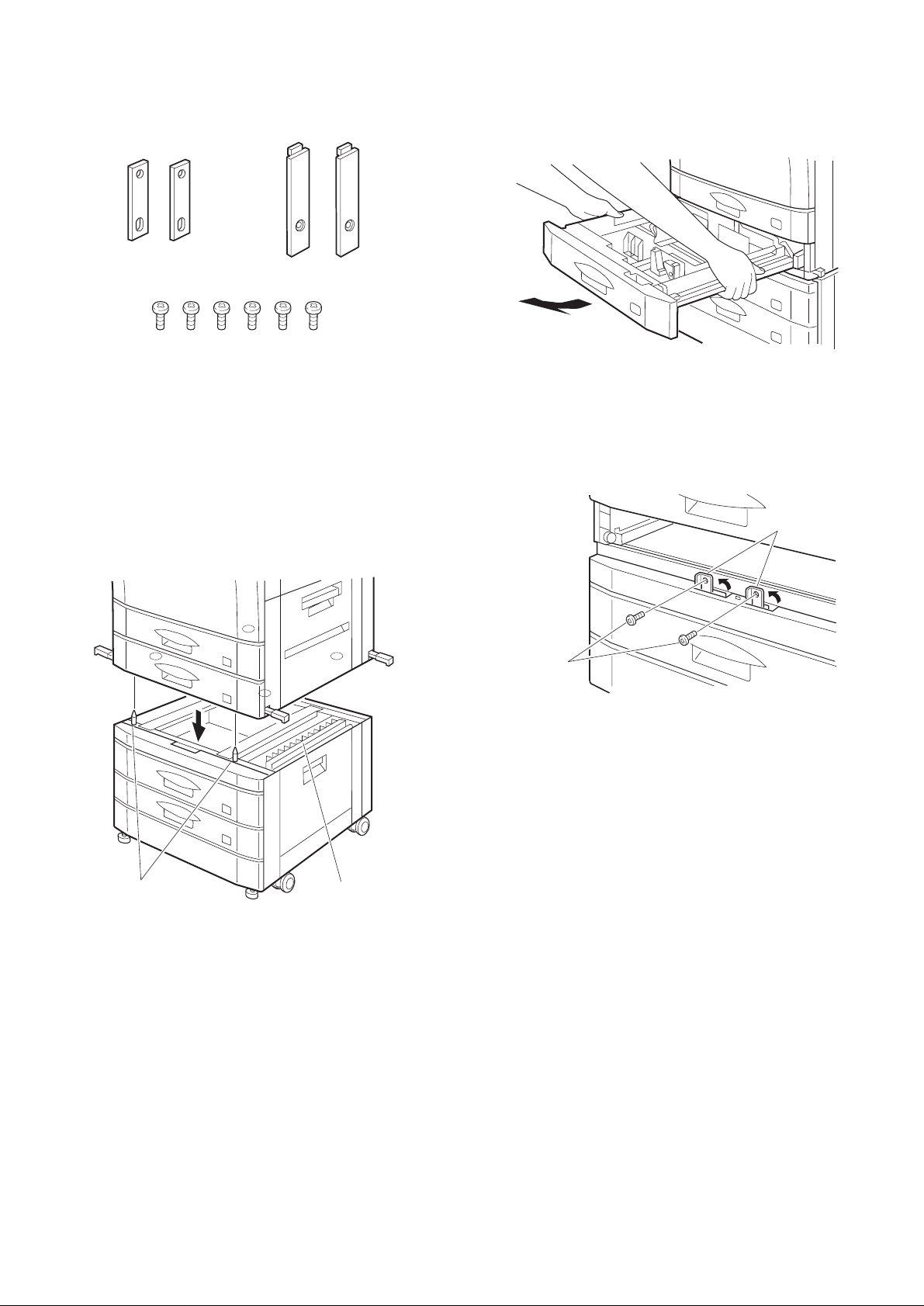
B. AR-DE1
Packed items
Connecting plate (2 pcs.) Connecting plate cover (2 pcs.)
Connecting screw (6 pcs.)
2. Remove th e tra y fro m th e co pier.
Pull the lower tray out until it stops.
Then hold and lift the tray to remove.
Remove the po w er plug of th e co pier fro m th e po w er
outlet, then perform the following procedures.
1. Put the copier on the des k.
Hold the knobs of the copier and fit the desk precisely with the desk
and put the copier on the desk.
Be sure to check that the positioning pins (2 pcs.) of the desk (top
front) are securely in the positioning holes.
Be careful that the copier and the bottom are not in contact with the
desk paper guide.
3. Connect the copier and the desk.
• Front connection
Put the connecting plate of the desk as shown, and f ix the copier
and the desk with the connecting screws (2 pcs.).
Front
Connecting plates
Connecting
screws
Portioning pins
Paper guide
3 – 3
Page 7
• Side connection
Attach the connecting plates to the copier and the desk with the
round hole upside. Insert the connecting screws into the round
holes and fix.
Insert the connecting plate cover into the external fitting of the
copier and fix the copier and the desk with the connecting screw.
(1 pc. for each)
★ The connecting screw serves not only as the fixing screw but also
as an electrical grounding for the copier and the desk. Be sure to
fix the connecting screw.
Install the tray which was removed in procedure 2.
5. Connect the desk connector.
Remove the connector cover fixing screw for connecting the desk
interface harness connector on the copier side, and remove the connector cover.
Connect the desk interface harness connector with the copier connector, and tighten the screw of the connector to fix the connector.
Connector cover
Fixing screw
Right side
Left side
Connecting plate
Connecting plate cover
Connecting screw
Connecting plate
Connecting plate
Connecting screw
Connecting plate cover
Connecting screw
Left side
4. Remove the package fixture of the tray.
Hold the knob of the tray and pull out the tray from the desk until it
stops.
Turn the package fixture which is fixing the paper falling/rising plate in
the tray in the arrow direction.
When shipping it is set to A3 size.
When selecting the paper size, perform paper selection.
The procedures are the same as those of the copier.
Fixture
Desk side connector
Screw
6. Move the copier to the installing position.
7. Lock the caster.
Set the lock lever of the caster which is on the front lower side of the
desk in the arrow direction and lock the caster.
Lock lever
Lock lever
8. Fix the desk to th e floo r.
Loosen the lock nut of the adjuster with a wrench or nippers.
Turn the adjuster in the arrow direction until it reaches the floor. Fix all
the adjusters (4 pcs.) to the floor.
After fixing the adjusters, turn the lock nut fully upward.
Lock nut
Adjuster
Lock nut
Adjuster
Insert the power plug of the copier into the power outlet, and turn on
the power and perform the following procedures.
3 – 4
Page 8
C. AR-CS1
Packed items
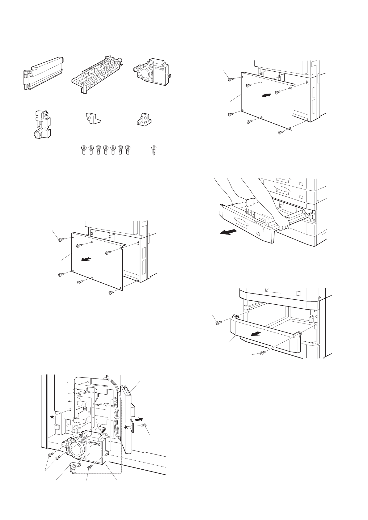
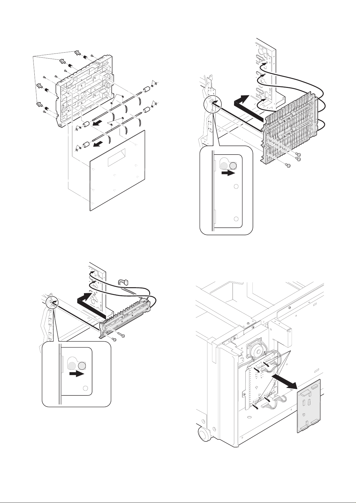
3. Install the rea r cab in et of th e de sk .
Install the rear cabinet which was removed in procedure 1 to the
original position, and fix it with fixing screws (6 pcs.).
Fixing screw (6 pcs.)
Tray rail left
(1 pc.)
Tray rail right cover
(1 pc.)
Paper fed unit
(1 pc.)
Stopper left
(1 pc.)
Fixing screw A
(M4 x 10) (7 pcs.)
Lift up unit
(1 pc.)
Stopper right
(1 pc.)
Fixing screw B
(M4 x 16) (1 (pc.)
Remove the po w er plug of th e co pier fro m th e po w er
outlet and perform the following procedure.
1. Remove the rear cabinet of the desk.
Remove the fixing screws (6 pcs.) of the rear cabinet of the desk, an d
remove the rear cabinet.
Fixing screw (6 pcs.)
Rear cabinet
Rear cabinet
4. Remove th e de sk tray .
Pull out the tray (which is above the tray to be installed) until it stops.
Hold the both sides of the tray and lift it to remove.
5. Remove th e co ve r.
Remove the fixing screws (2 pcs.) of the cover of the tray to be
installed, and remove the cover.
2. Install the lift up unit.
Remove the fixing screw (section ★) of the desk PWB mounting
plate, and open the desk PWB mounting plate.
Attach the lift up unit to the rear frame of t he desk and slide it to the
left.
Fix the lift up unit with the fixing screws A (3 pcs.) and connect the
desk PWB connector to the lift up unit connector.
Return the desk PWB mounting plate to the original position, and fix it
with the fixing screw (section
Fixing screw A
Desk PWB connector
★).
Fixing screw A
Desk PWB mounting
plate
Desk mounting
plate fixing screw
Lift up unit
Fixing screw
Cover
Fixing screw
3 – 5
Page 9

6. Install the tray rail lef t.
Insert the tray rail left into the positioning section of the frame on the
left side of the desk. Put the tray rail onto the fram e and fix it with
fixing screw A (1 pc.).
Positioning section
Positioning
section
Fixing screw A
9. Set the tray.
Lift the both sides of the rear of the tray, fit the tray guide with the tray
rail, and push it along the tray rail into the desk.
Check that the tray moves smoothly.
Tray rail left
7. Install the paper feed unit.
Put the paper feed unit on the guide rail and push it until it stops.
Engage the front side of the paper feed unit with the positioning boss
(2 positions) of the desk frame, and fix it with the fixing screw (1 pc.).
Paper feed unit
Positioning boss
Fixing screw A
Guide rail
8. Install the tray rail righ t co ve r.
Insert the positioning bosses (2 positions) of the tray rail right cover
into the positioning holes of the front frame on the right side of the
desk, and fix with the fixing screws A (2 pcs.).
10. Set the tray which was removed in procedure 4.
Lift the both sides of the rear of the tray, fit the tray guide with the tray
rail, and push it along the tray rail into the desk.
Check that the tray moves smoothly.
11. Install the stopper.
Pull out the upper tray.
Fix the stopper left to the left tray rail with the fixing screw B (1 pc.).
Fix the stopper right tot he tray rail right cover.
Left side Right side
Stopper left
Fixing screw B
Stopper right
Positioning boss
Tray rail right cover
Fixing screws A
Positioning boss
Select the paper size according to the paper to be used.
The selecting procedure is the same as that of the main body.
Fixing screw
Insert the power plug of the copier into the power outlet and turn o n
the power. Perform the following procedure.
3 – 6
Page 10
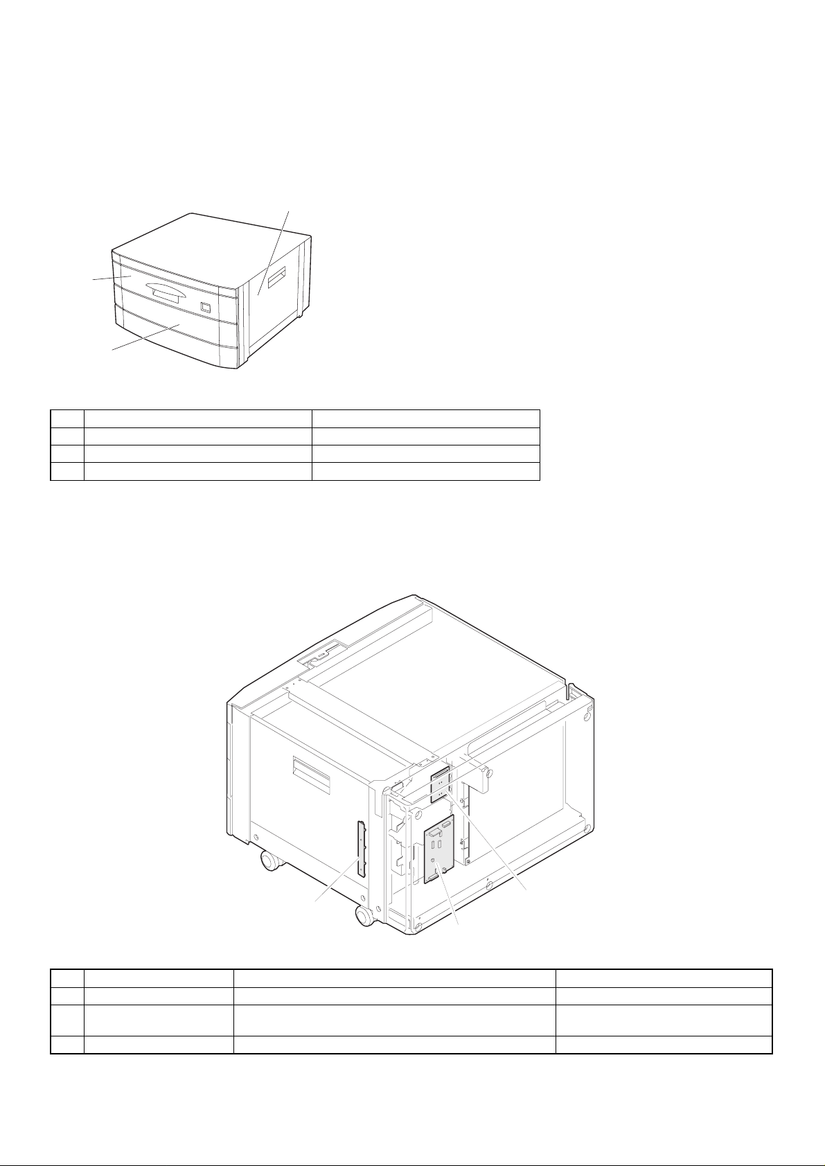
[4] EXTERNAL VIEW AND INTERNAL STRUCTURE
1. External v iew
1
2
3
No. Name Remark
1 Side cover
2 Tray Similar with AC-CS1.
3 Preliminary paper feed section For option (AR-CS1)
2. Interna l structu re
1) PWB
2
3
1
No. Unit name Function Remark
1 Desk main PWB unit Control the desk unit
2 Paper detector PWB Paper detection in the middle and the lower stage, and right
3 Lift up PWB Lift up PWB for the top stage (Included in the lift up unit.)
door open detection.
4 – 1
Page 11
2) Sensors and detectors
9.DCSPD1
2.DLUD2
1.DLUD1
3.DPED1
5.DPOD1
6.DPOD2
8.DDOPSW
7.DPOD3
4.DPED2
No. Code Name Kind Function Remark
1 DLUD1 Desk lift up detector 1 Photo sensor Top tray lift up detection (LOW
2 DLUD2 Desk lift up detector 2 Photo sensor Middle tray lift up detection
3 DPED1 Desk paper empty detector 1 Photo sensor Top tray paper
4 DPED2 Desk paper empty detector 2 Photo sensor Middle tray paper
5 DPOD1 Desk paper exit detector 1 Photo sensor Top stage paper exit detection
6 DPOD2 Desk paper exit detector 2 Photo sensor Middle stage paper exit
7 DPOD3 Desk paper exit detector 3 Photo sensor Low stage paper exit detection For AR-DE2 only (Included in
8 DDOPSW Desk right door open/close
detector
9 DCSPD1 Desk remaining paper quantity
detector 1 (Top stage)
10 DCSPD2 Desk remaining paper quantity
detector 2 (Middle stage)
Photo sensor Right door open/close detection (Included in the paper exit
Photo sensor Remaining paper quantity
Photo sensor Remaining paper quantity
when lift up.)
(LOW when lift up.)
(presence/empty) detection
(LOW at paper presence)
(presence/empty) detection
(LOW at paper presence)
detection
detection (For top stage)
detection (For middle stage)
4 – 2
(Included in the paper feed
unit.)
For AR-DE2 only (included in
the paper feed unit.)
(Included in the paper feed
unit.)
For AR-DE2 only (Included in
the paper feed unit.) (Similar
with AR-CS1.)
(Included in the paper exit
PWB.)
the paper feed unit.)
PWB.)
(Included in the lift up PWB.)
For AR-DE2 only (Included in
the lift up PWB.) (Similar with
AR-CS1.)
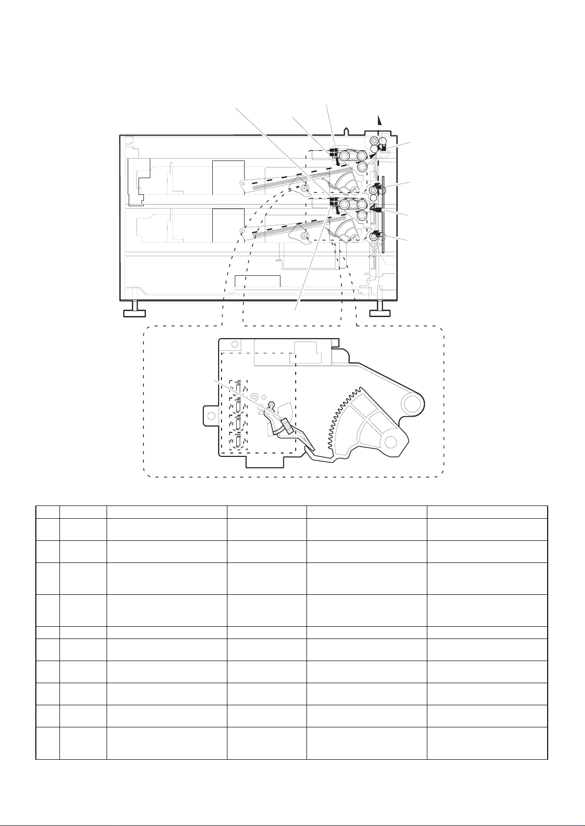
Page 12

3) Clutches, motors, and solenoids
5.DPFS1
2.DLUM1
7.DPFC1
1.DM
4.DTRC
8.DPFC2
3.DLUM2
6.DPFS2
No. Code Name Kind Function Remark
1 DM Desk motor Brushless motor Desk transport mechanism
2 DLUM1 Desk lift up motor 1 Synchronous motor Top tray lift/fall plate drive
3 DLUM2 Desk lift up motor 2 Synchronous motor Middle tray lift/fall plate drive
4 DTRC Desk vertical transport roller
clutch
5 DPFS1 Desk paper feed solenoid 1 Solenoid Top tray paper takeup roller
6 DPFS2 Desk paper feed solenoid 2 Solenoid Middle tray paper takeup roller
7 DPFC1 Desk paper feed clutch 1 Magnetic clutch Top tray paper transport roller
8 DPFC2 Desk paper feed clutch 2 Magnetic clutch Middle tray paper transport
Magnetic clutch Vertical transport mechanism
drive
drive and transmission
drive
For AR-DE2 only
drive
drive
For AR-DE2 only
roller drive
4 – 3
Page 13

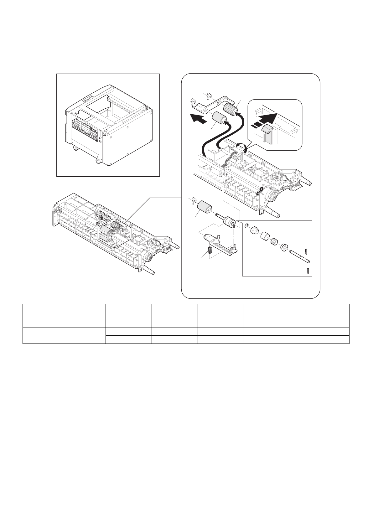
[5] DISASSEMBLY AND ASSEMBLY
1. Paper feed unit
2)
1) 3)
2)
A. Paper feed, Pic up, Resist roller
1)
3)
3)
6)
5)
1)
1. When attaching the clutch, be sure to fit the clutch notch into
the B portion as shown in the figure above.
2. When inserting the shaft into the roller, attention shall be paid
so that the pin C on the shaft faces down.
4)
2)
B
7)
8)
C
5 – 1
Page 14

2. Paper tr an sfer
B. Paper transfer roller
3)
2)
A. Paper transfer cover
1)
2)
1)
2)
3)
2)
1)
1)
4)
4)
1)
5)
6)
6)
4)
4)
6)
1)
3)
1)
2)
6)
5)
3)
2)
2)
5 – 2
5)
3)
2)
1)
1)
1)
1)
Page 15
C. Paper tra nsfer idle roller
1)
1)
1)
1)
1)
2)
6)
2)
2)
2)
4)
4)
5)
6)
2)
5)
2)
6)
4)
2)
4)
4)
4)
D. Transport paper guide
Attach the transport paper guide fully to the rear frame side (in the
arrow direction).
3. Desk control PWB, Pa p er tr an s fer motor
2)
1)
1)
1)
3)
1)
5 – 3
Page 16

5. Lift up unit
6)
7)
4. Drive unit
2)
1)
2)
6)
1)
5)
3)
3)
4)
2)
1)
5)
3)
3)
4)
3)
5 – 4
Page 17

[6] ADJUSTMENTS
1. Adjust the cabinet surface position.
Loosen the fixing screws (4 pcs.) which are fixing the front cabinet,
and shift the front cabinet in the arrow direction to adjust the position.
a
Direction A
bba
Direction B
6 – 1
Page 18
[7] MAINTENANCE
1. Paper feed se ction
1
1
1
2
3
No. Name Work item Cycle Model Remark
1 Rollers Check 80 K AR-DE1 Reference: paper feed port counter
2 Brake spring Lubricate 160 K AR-DE1
3 Torque limiter Check 80 K AR-DE1
Replace 120 K or 2 years AR-DE1 Reference: Paper feed port counter
7 – 1
Page 19

2. Paper tran spo rt sectio n
1
2
1
2
1
2
No. Name Work item Cycle Model Remark
1 Transport rollers Clean 80 K AR-DE1
2 Rollers Clean 80 K AR-DE1
2
2
2
7 – 2
Page 20

3. Drive section, others
2
1
3
/
No. Name Work item Cycle Model Remark
1 Gears Lubricate 80 K AR-DE1
2 Belts Check 240 K AR-DE1
3 Sensors Check 80 K AR-DE1
3
7 – 3
Page 21

[8] TROUBLESHOOTING
1. Trouble code list
Trouble
code
U6 00 Desk communication trouble Desk
01 Desk 1 CS lift up trouble Desk
02 Desk 2 CS lift up trouble Desk
03 Desk 3 CS lift up trouble Desk
08 Desk 24V power abnormality Desk
10 Desk transport motor trouble Desk
Trouble content Remark
2. Details
Trouble
code
U6 00 Content Desk communication trouble
Detail Communication error with the desk.
Cause Improper connection or disconnection of
Check
and
remedy
Content Desk 1, 2, 3 tray lift up trouble
01
∼
Detail Desk 1, 2, 3 tray lift up trouble
03
Cause Sensor trouble
Check
and
remedy
08 Content Desk 24V power trouble
Detail DC24 V is not supplied to the desk.
Cause Improper connection or disconnection of
Check
and
remedy
10 Content Desk transport motor trouble
Detail Desk transport motor operation trouble
Cause Motor lock
Check
and
remedy
Error during the communication line test
after turning on the power or after exiting
the simulation mode.
the connector and the harness.
Desk control PWB trouble
Control PWB (PCU) trouble
Malfunction due to noises
Canceled by turning off/on the power.
Check the connector and the harness of
the communication line.
Desk control PWB trouble
Gear breakage
Lift up motor trouble
Check the lift up sensor operation with
SIM 4-2.
Check the lift up motor operation with SIm
4-3.
the connector and the harness.
Desk control PWB trouble
Power unit trouble
Check the connector and the harness of
the power line.
Check 24V supply with the power unit and
the desk control PWB.
Motor RPM abnormality
Overcurrent to the motor
Desk control PWB trouble
Check the transport motor operation with
SIM 4-3.
Details of trouble
Trouble
detection
8 – 1
Page 22
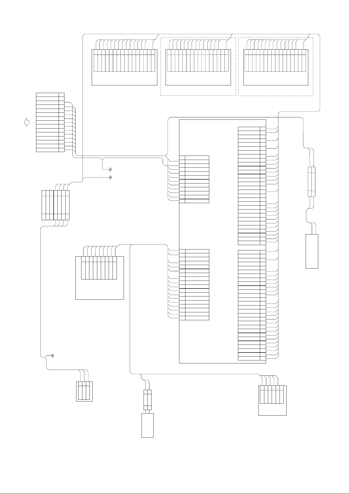
BRBRBRGYBRBRBR
BR
56789
3
1
2
4
DCSS11
DCSS12
DCSS13
DCSS14
GND2
/FOUND1
DLUMB1
BL
PK
PK
BR
10111213141516
DLUMA1
+5V
DPED1
/DLUD1
PLPLPL
PLGYPL
BR
BR
RD
/DPFS1
/DPFC1
+24V
N.C.
DCSPD12
1
DCSS21
2
DCSS22
3
4
DCSS23
DCSS24
PL
56789
GND2
/FOUND2
PL
BL
PK
DLUMB2
DLUMA2
+5V
PLPLRD
PL
PK
10111213141516
DPED2
/DLUD2
/DPFS2
/DPFC2
+24V
N.C.
DCSPD22
LBLBLB
LBGYLBLBLBBLPKPKLBLBRD
56789
3
1
2
4
DCSS31
DCSS32
DCSS33
DCSS34
GND2
/FOUND3
DLUMB3
10111213141516
DLUMA3
+5V
DPED3
/DLUD3
LB
/DPFS3
/DPFC3
+24V
N.C.
DCSPD32
N.C.
N.C.
FG
/TRC-DSK
RES-DSK
/DSR-DSK
/DTR-DSK
RXD-DSK
TXD-DSK
To copier
GND1
+24V
GND2
+5V
DH100
DH100
PPD interface harness
15
14
GY
13
PK
12
BR
11
LB
10
PK
9
PL
8
BR
7
GY
6
RD
5
GY
4
BL
3
WH
2
BK
1
GY
1
2
N.C.
N.C.
1
2
GY
567
3
N.C.
DPPD5V
/DPOD1
GND2
FG
44
567
3
PKGYGY
Desk main motor
Top stage lift up UN
PKLBPLBLGYBRPKLBPL
4
1
2
56789
3
+5V
DMHW
DMHV
DMHU
GND1
DMRE
DMW
DMV
Copier interface harness H
(Japan spec.)
Copier interface harness
(EX spec.)
Drive system harness
DMU
Middle stage lift up UN
AR-DE2 standard provision
AR-DE1 option (AR-CS1)
12
N.C.
PK
/TRC-DSK
11
GY
10
GND2
BR
+5V
9
BL
/DSR-DSK
8
LB
7
HV
GY
6
GND1
PK
/DTR-DSK
5
RD
4
+24V
PL
3
/RXD-DSK
GY
2
GND2
BR
1
TXD-DSK
BR
/DTRC
18
PK
DMW
17
16
N.C.
LB
DMV
15
RD
+24V
14
PL
DMU
13
12
N.C.
GY
11
GND1(DM)
GY
10
GND2
PK
HW
9
PL
8
DDOPSW
LB
7
HV
LB
6
/DPOD3
PL
5
HU
PL
4
/DPOD2
BR
3
DMRE
BL
2
+5V
BL
1
+5V(DM)
CN-D CN-C
DESK-MAIN
PWB
CN-A CN-B
Lower stage lift up UN
AR-DE2 option
AR-DE2 paper feed system harness 3-cassette
AR-DE1 paper feed system harness 2-cassette
LB
30
DCSS34
DCSS24
N.C.
DCSS14
N.C.
DCSPD32
N.C.
DCSPD22
DCSPD12
DCSS33
/DLUD3
DCSS23
DPED3
DCSS13
DPED1
N.C.
/DLUD1
N.C.
N.C.
DCSS32
/DLUD2
DCSS22
DPED2
DCSS12
/FOUND3
DCSS31
/FOUND2
DCSS21
/FOUND1
DCSS11
/DPOD1
N.C.
GND2
N.C.
N.C.
DLUMB1
GND2
DLUMA1
GND2
DLUMB2
GND2
DLUMA2
N.C.
DLUMB3
DPPD5V
DLUMA3
+5V
/DPFC3
+5V
/DPFC2
+5V
/DPFC1
+24V
/DPFS3
+24V
/DPFS2
+24V
/DPFS1
PL
29
28
BR
27
26
LB
25
24
PL
23
BR
22
LB
21
PK
20
PL
19
PK
18
BR
17
PK
16
15
PK
14
13
12
LB
11
PK
10
PL
9
PK
8
BR
7
LB
6
LB
5
PL
4
PL
3
BR
2
BR
1
PK
28
27
GY
26
25
24
BR
23
GY
22
BR
21
GY
20
PL
19
GY
18
PL
17
16
LB
15
BL
14
LB
13
BL
12
LB
11
BL
10
PL
9
BL
8
BR
7
RD
6
LB
5
RD
4
PL
3
RD
2
BR
1
BK
WH
WH
1
2
DH100
DH100
1
2
WH
(Japan spec. only)
WH
WH
H version heater
Dehumidifying heater
BLGYPK
2
3
DPPD5V1/DPOD1
GND2
Top stage paper exit sensor
[9] ELECTRICAL SECTION
1. Actual wiring diagram
GYLBPL
PL
RD
BR
1
2
+24V
/DTRC
1
2
DTRC
1BL23456
+5V
GND2
/DPOD3
PFD PWB UN
/DPOD2
DPOPSW
.N.C.
Transport roller clutch
9 – 1
Page 23

Top tray
DPED1
/DLUD1
paper detection
Upper limit detection
Paper feed SOL
DPED2
/DLUD2
/DPFS2
Paper feed SOL
paper feed SL
/DPFC2
Paper feed unit
/DPFS1
paper feed SL
/DPFC1
Paper feed unit
Middle tray
paper detection
Upper limit detection
DPED3
Lower tray
paper detection
/DLUD3
/DPFS3
/DPFC3
paper feed SL
Paper feed SOL
Upper limit detection
Paper feed unit
DH100
DC power
supply circuit
/TRC-DSK
RES-DSK
Copier body
/DSR-DSK
/DTR-DSK
RXD-DSK
TXD-DSK
/FOUND
Paper feed
unit detection
DCSPD12
Remaining paper
quantity detection
DCSS11
DCSS12
DCSS13
Interface PWB
DLUMA1
DLU B1
Lift up motor
2
DCSS14
Tray size detection
Lift up unit
5V
24V
/FOUND2
Paper feed
unit detection
DCSPD22
Remaining paper
quantity detection
DCSS11
DCSS12
DCSS13
Interface PWB
DLUMB1
DLUMA1
2
DCSS14
Tray size detection
Lift up motor
Lift up unit
/FOUND3
Paper feed
AR-DE2 standard provision
AR-DE1 option (AR-CS1)
unit detection
DCSPD32
Remaining paper
quantity detection
DCSS31
DCSS32
DCSS33
Interface PWB
DLUNB3
DLUMA3
2
DCSS34
Tray size detection
Lift up motor
Lift up unit
H version heater
Japan spec. only
AR-DE2 option (AR-CS1)
Dehumidifying heater
DMHV
DMHW
DMHU
Hall element
2. System blook diagram
Desk main motor
2
DPPD5V
Desk main PWB
5V
24
24V
1
Motor
DMRE
DMW
DMV
Encoder
DMU
2
220
/DPOD1
Top stage paper exit sensor
4
/DTRC
Transport roller clutch
1
/DPOD2
2
PFD PWB unit
Middle stage paper exit sensor
Right door open/close sensor
/DPOD3
DDOPSW
2
2
Lower stage paper exit sensor
9 – 2
Page 24

(DLUM1)
Lift up motor
(DLUM2)
Lift up motor
(DLUM3)
Lift up motor
(DPFC)
Paper feed clutch
paper feed
(DTRC)
Transport clutch
solenoid (DPFS)
Paper empty sensor
(DLUD)
(DPED)
Top cassette
remaining paper
Upper limit sensor
(DPCD)
(DCSPD)
Door open/close
Paper exit sensor
quantity detection
sensor (DDCPSW)
+24V
+10V
(24vm)
24V monitor
P36
P17
P63
IC03
driver
P34,P35
P62
Output
IC05
driver
Output
P32,P33
(2)
section
IC06
driver
P30,P31
section (1)
P64
RES,RXD,P46,P47
IC11
C P U
TXD,P52
IC01
driver
P10~P17
X1,X2
Output
section
(1)
P70,P72
P40~P42,
P21~P27
Input
section
(2)
IC02
driver
IC07
driver
(DTRC)
Transport clutch
Transport
motor (DM)
3. Main PWB blook diagram
+5V
IC04
driver
+5V
IC10
IC12
amplifier
operation
Motor drive section
X1
section
Communication
PWB
Copier main
(8.00MHz)
Input
MULTI
IC08,IC09
8-CHANNEL
(1)
section
(DCSS)
Tray size detection
PLEXER
stage tray paper
remaining quantity
Middle stage, lower
sensor (DCSPD2, 3)
9 – 3
Page 25
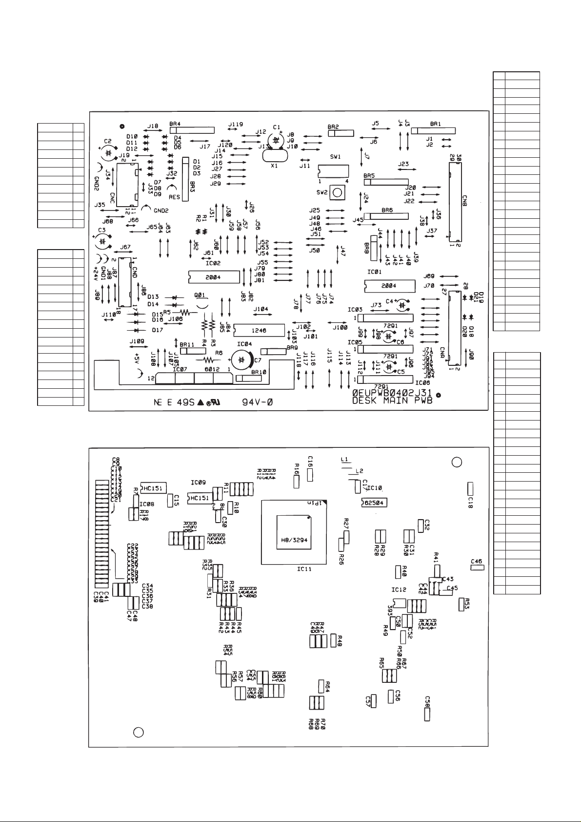
4. Parts arrangement
CN-C
TXD-DSK
GND2
/RXD-DSK
+24V
/DTR-DSK
/DSR-DSK
+5V
/RES-DSK
GND2
/TRC-DSK
N.C.
CN-D
+5V(DM)
+5V
DMRE
/DPOD2
HU
/DPOD3
HV
DDOPSW
HW
GND2
GND1(DM)
N.C.
DMU
+24V
DMV
N.C.
DMW
/DTRC
1
2
3
4
5
6GND1
7
8
9
10
11
12
1
2
3
4
5
6
7
8
9
10
11
12
13
14
15
16
17
18
CN-B
1
2
3
4
5
6
7
8
9
10
11
12
13
14
15
16
17
18
19
20
21
22
23
24
25
26
27
28
29
30
CN-A
1
2
3
4
5
6
7
8
9
10
11
12
13
14
15
16
17
18
19
20
21
22
23
24
25
26
27
28
DCSS11
/FOUND1
DCSS21
/FOUND2
DCSS3
/FOUND3
DCSS12
DPED2
DCSS22
/DLUD2
DCSS32
N.C.
N.C.
/DLUD1
N.C.
DPED1
DCSS13
DPED3
DCSS23
/DLUD3
DCSS33
DCSPD12
DCSPD22
N.C.
DCSPD32
N.C.
DCSS14
N.C.
DCSS24
DCSS34
/DPFS1
+24V
/DPFS2
+24V
/DPFS3
+24V
/DPFC1
+5V
/DPFC2
+5V
/DPFC3
+5V
DLUMA3
DPPD5V
DLUMB3
N.C.
DLUMA2
GND
DLUMB2
GND
DLUMA1
GND2
DLUMB1
N.C.
N.C.
GND2
N.C.
/DPOD1
9 – 4
Page 26

COPYRIGHT 1998 BY SHARP CORPORATION
All righ ts reserved.
Printed in Japan.
No part of this publicatio n may be reproduce d,
stored i n a retrieval s ystem, or transmit ted.
In any form or by any means,
electron ic, mechanical, p hotocopying, re cording, or othe rwise,
without prior written permission of the publisher.
SHARP CORPORATION
Printing Reprographic Systems Group
Quality & Reliability Control Center
Yamatokoriyama, Nara 639-1186, Japan
1998 May Printed in Japan
 Loading...