

Page 1
CODE : 00Z
q
SERVICE MANUAL
CONTENTS
Parts mark ed w ith "!" are important for maintaining the safety of the set. Be sure to replace these parts with specified
ones for maintaining the safety and performance of the set.
SHARP CORPORATION
This document has been pub lished to be used
for after sales service only.
The contents are subject to change without notice.
ARD29//A1E
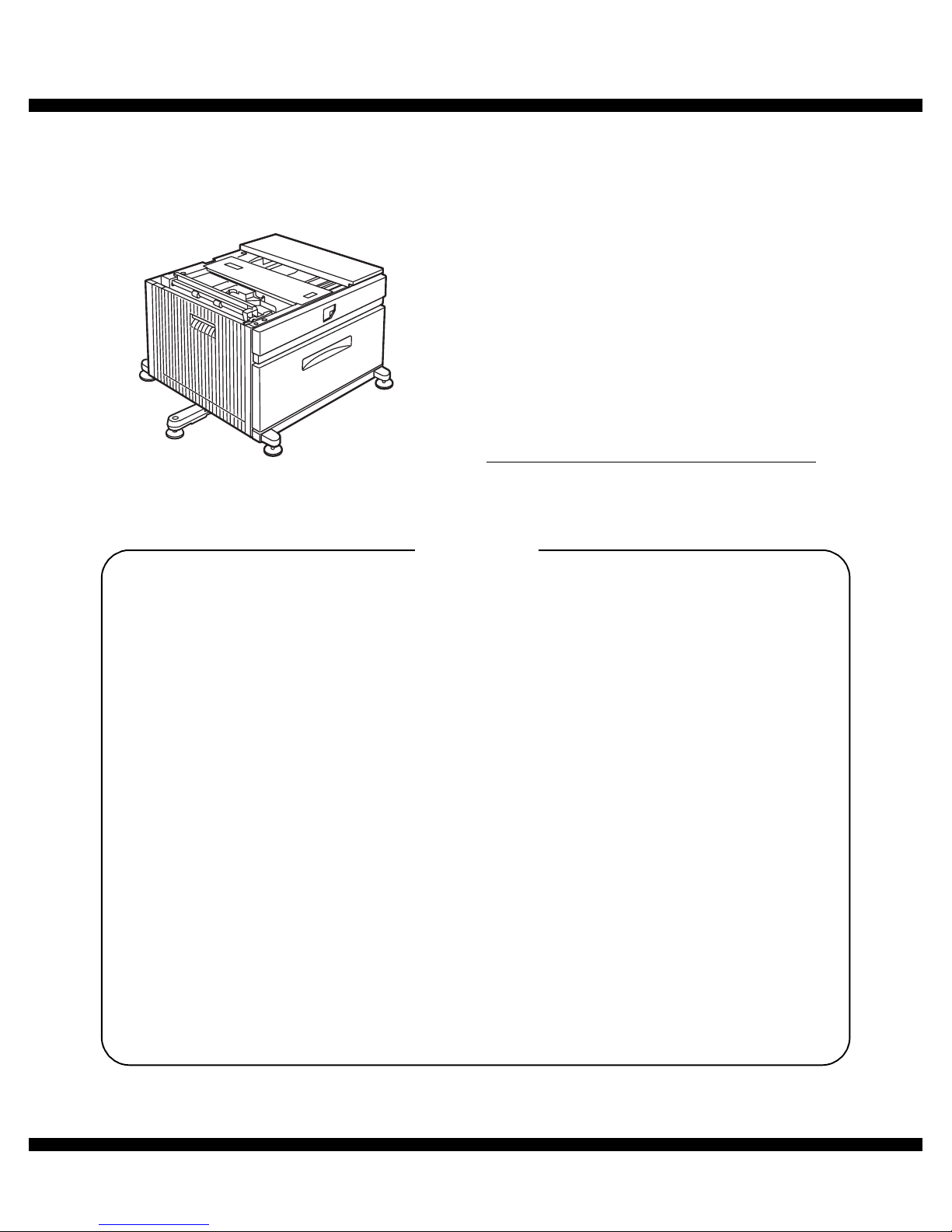
LASER PRINTER OPTIONS
PAPER FEED UNIT
MODEL
AR-D29
[1] PRODUCT OUTLINE . . . . . . . . . . . . . . . . . . . . . . . . . . . . . . . . . 1 - 1
[2] CONFIGURATION . . . . . . . . . . . . . . . . . . . . . . . . . . . . . . . . . . . 2 - 1
[3] SPECIFICATIONS . . . . . . . . . . . . . . . . . . . . . . . . . . . . . . . . . . . 3 - 1
[4] UNPACKING AND INSTALLATION . . . . . . . . . . . . . . . . . . . . . . 4 - 1
[5] EXTERNAL VIEWS AND INTERNAL STRUCTURES . . . . . . . . 5 - 1
[6] ADJUSTMENTS . . . . . . . . . . . . . . . . . . . . . . . . . . . . . . . . . . . . . 6 - 1
[7] DISASSEMBLY AND ASSEMBLY, MAINTENANCE . . . . . . . . . 7 - 1
[8] BLOCK DIAGRAM, WIRING DIAGRAM,
CIRCUIT DIAGRAM, PARTS ARRANGEMENT. . . . . . . . . . . . . 8 - 1
PARTS GUIDE
Page 2
AR-D29 PRODUCT OUTLINE
1 – 1
[1] PRODUCT OUTLINE
This unit is installed to one of the following machines to serve as a Paper feed module.
When installing one of the following machines, the stand with multi-purpose tray (AR-D29) must be installed in advance.
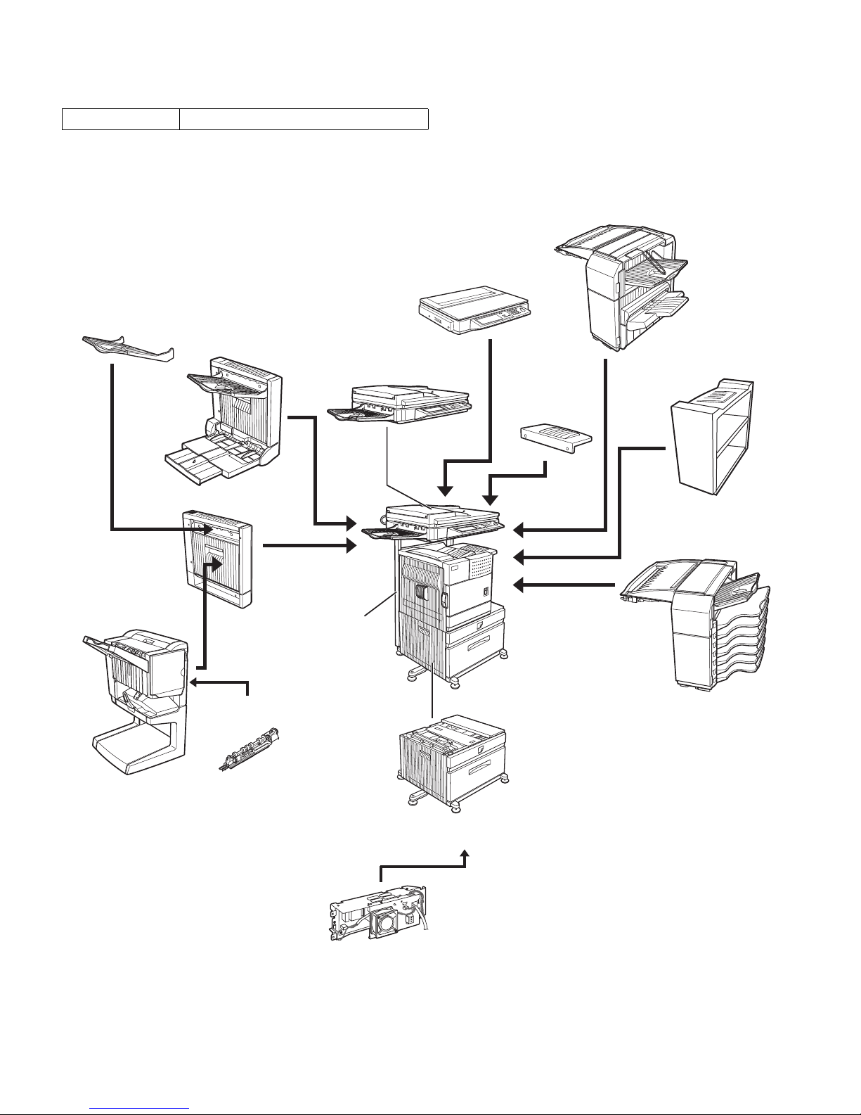
[2] CONFIGURATION
For combinations of options, refer to "C. List of com bination of peripheral devices" described later.
Applicable models AR-M312U/AR-M420U
Upper exit tray
(AR-TE4)
Finisher
(AR-FN6)
Mail-bin stacker
(AR-MS1)
Stand with multipurpose drawer
(AR-D29)
Scanner rack
(AR-RK2)
Saddle stitch
finisher
(AR-FN7)
Duplex module
(AR-DU3)
Duplex module/
bypass tray
(AR-DU4)
Exit tray
(AR-TE3)
Right upper exit tray
(AR-TE5)
Scanner module with DSPF
(AR-EF6)
Scanner module with OC
(AR-EF5)
Punch unit
(AR-PN1A/B/C/D)
Power supply unit
(AR-DC1)
Page 3

AR-D29 SPECIFICATIONS
3 – 1
[3] SPECIFICATIONS
Model name AR-D29
Type Stand with multi-purpose drawer
Transport speed To support 31-42 sheet/minute
Transport alignment Center alignment
Paper size A3, B4, A4, A4R, B5, B5R, A5R
11" x 17", 8.5" x 14", 8.5" x 13", 8.5" x 11",
8.5" x 11"R, 5.5" x 8.5"R
Executive, Japanese p/c, Monarch ( envelop e)
Com-10 (envelope), DL (envelope),
C5 (envelope), ISO B5 (envelope)
How to change
the paper size
Guide adjustment by user/
Software setting by user
Factory default paper size setting A3
Media available for paper feeding Plain paper : 60-128g/m² / 16-34lbs
Index paper : 176g/m² / 47lbs
Cover paper: 200-205g/m² / 54-55lbs
Envelope : 75-90g/m², 20-24lbs
Transparency film
*
Media heavier than 105g/m² should be A4/8.5 x 11" or smaller. Media heavier than 128g/m² should be fed
from shorter edge.
*
Only single paper feed is enabled for overlay copy or copy on back-side of printed paper.
Paper capacity Standard: 500sheets (80g/m²)
Post card: 40sheets
Envelope: 40sheets
Transparency film: 40sheets
Paper type Plain, recycled, pre-pri nted, pre-pun ched , color, l ett er head, labels, he avy, tr anspa rency, Jap anese p/ c, envel ope
(User can set bi-type for each of the above paper type.)
Sizes to be detected Auto detection-AB: A3, B4, A4, A4R, B5, B5R, 8.5"x13", A5R
Auto detection-Inch: 11" x 17", 8.5" x 14", 8.5" x 11", 8.5" x 11"R, 7.25" x 10.5"R, 5.5" x 8.5R
Manual (input detection):
postal card, Monarch (envelope), Com-10 (envelope), DL (envelope), C5 (envelope), ISO B5 (envelope)
Ignore detection selectable:
Paper balance detection Provided (paper empty and 3 steps)
Paper loading system To be loaded from the upper side with front loading system
Tray ascent/
descent time
Ascent Within 7 seconds
At paper empty, required time from tray insert to the empty detection
Descent Own weight descent
Dehumidification heater Not provided
Power consumption 24.5W or lower
Power source Supplied from main unit (DC24V 1A / DC5V 0.1A)
External dimensions 589 x 630 x 404 (mm)
Occupied dimensions 963 x 665 (mm)
Weight Approx. 25.2kg
Page 4
AR-D29 UNPACKING AND INSTALLATION
4 – 1
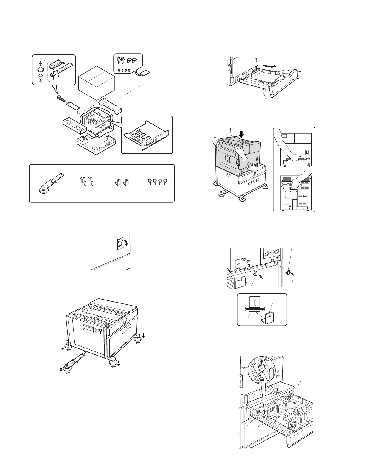
[4] UNPACKING AND INSTALLATION
<BEFORE INSTALLATION>
• Start installation after checking that the DATA and COMMUNICATION indicators on the operation panel are neither lit nor blinking.
1) Turn off the main switch of the main unit of the printer.
Turn the main switch located on the front side of the printer to the
"OFF" position.
Then remove the power plug from the outlet.
2) Attach the adjusters and adjust them.
<1>Insert the left adjusters to the stand/paper drawer.
<2>Turn the each adjusters to lower them until they touch the floor.
*
Be sure to attach the left adjuster to prevent overturning.
Caution: The lower tray cannot be pulled out unless the adjuster is low-
ered to the specified position.
3) Put the main unit of the printer on the stand/paper drawer.
<1>Pull out the paper tray of the main unit until it stops and then
remove it by lifting both ends of the tray.
<2>Hold the main unit of the printer at the positions shown in the illus-
tration and put the main unit on the stand/paper drawer so that the
front side and the left side of the main un it are aligned to those of
the stand/paper drawer.
Caution: For installation of the main unit, it must be held by two persons
and installed without haste.
4) Connect the main unit to the stand/paper drawer.
<1>Attach the rear mounting plates using a supplied screw for each.
Caution: Insert the rear mounting plates under the desk frame.
<2>Pull out the upper paper tray of the stand/paper drawer until it stops
and attach the front mounting pla tes usin g a supp lied scre w for each .
Then, remove the lock of the paper tray and cl ose the tray .
<Parts included>
Left adjuster: 1 pc.
Front mounting
plates: 2 pcs.
Rear mounting
plates: 2 pcs.
Screws (M4x6):
4 pcs.
"OFF"
1
2
2
2
2
Frontside
Rearside
Rear mounting plate
Rear mounting plate
Screw
Screw
Desk frame
Rear
mounting plate
Screw
Screw
Front
mounting plate
Front mounting
plate
Page 5
AR-D29 UNPACKING AND INSTALLATION
4 – 2
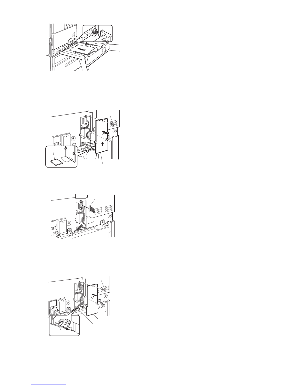
<3>Reattach the paper tray of the main unit.
5) Connect the power supply I/F harness to the PCU PWB of the
main unit of the printer.
<1>Remove the screw that fixes the harness co ver of the main unit of
the printer and slide the harness cover up to remove it.
Process the harness cover as shown in the illustration.
<2>Connect the connector of the relay harness of the multi purpose
drawer to the connector of the PCU PWB of the main unit of the printer.
<3>Reattach the power supply I/F harness cover to its original position
and fix it with the removed screw.
At this time, ensure that the power supply I/F harness are arranged
as shown in the illustration.
• Fix the harness securely to the wire saddle.
6) Attach the paper guides to the lower tray (large capacity tray) and
set the size.
Refer to "Setting and adjustment" described later.
*
If another peripheral device must be installed, carry out the following
step at the end of the installation work.
7) Adjust the position of the paper guides of the upper paper tray of
the stand/paper drawer.
Refer to "Setting and adjustment" described later.
8) Carry out the off center adjustment.
Harness cove
r
Cut out.
Screw
CN10
Connector
Wire saddle
Harness cove
r
Screw
Wire saddle
Page 6
AR-D29 EXTERNAL VIEWS AND INTERNAL STRUCTURES
5 – 1
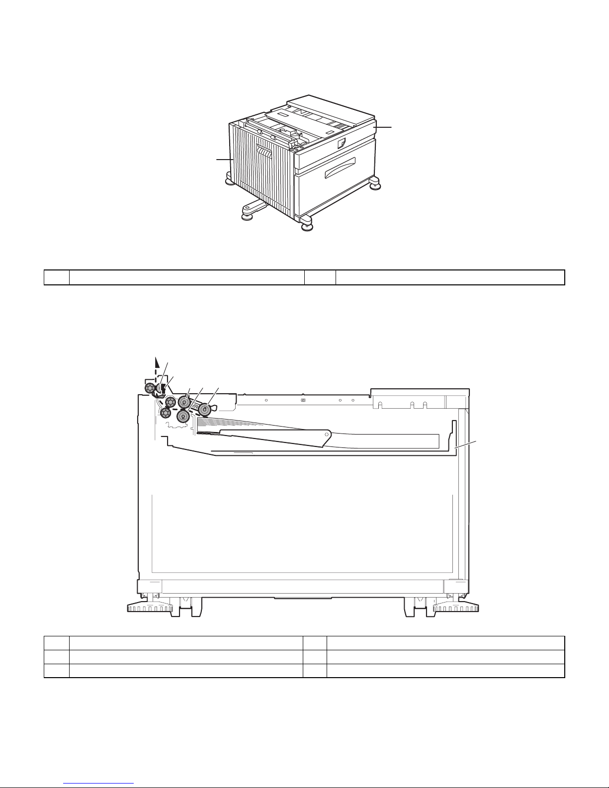
[5] EXTERNAL VIEWS AND INTERNAL STRUCTURES
A. EXTERNAL VIEW
B. INTERNAL STRUCTURE
1
2
1 Multi-purpose tray (No. 2 tray) 2 Desk left door
2
1. MCPPD
5
34
6
1 Multi-purpose tray paper transport sensor (MCPPD) 4 Multi-purpose tray separation roller
2 Multi-purpose tray paper transport roller 5 Multi-purpose tray paper take-up roller
3 Multi-purpose tray paper feed roller 6 Multi-purpose tray
Page 7
AR-D29 EXTERNAL VIEWS AND INTERNAL STRUCTURES
5 – 2
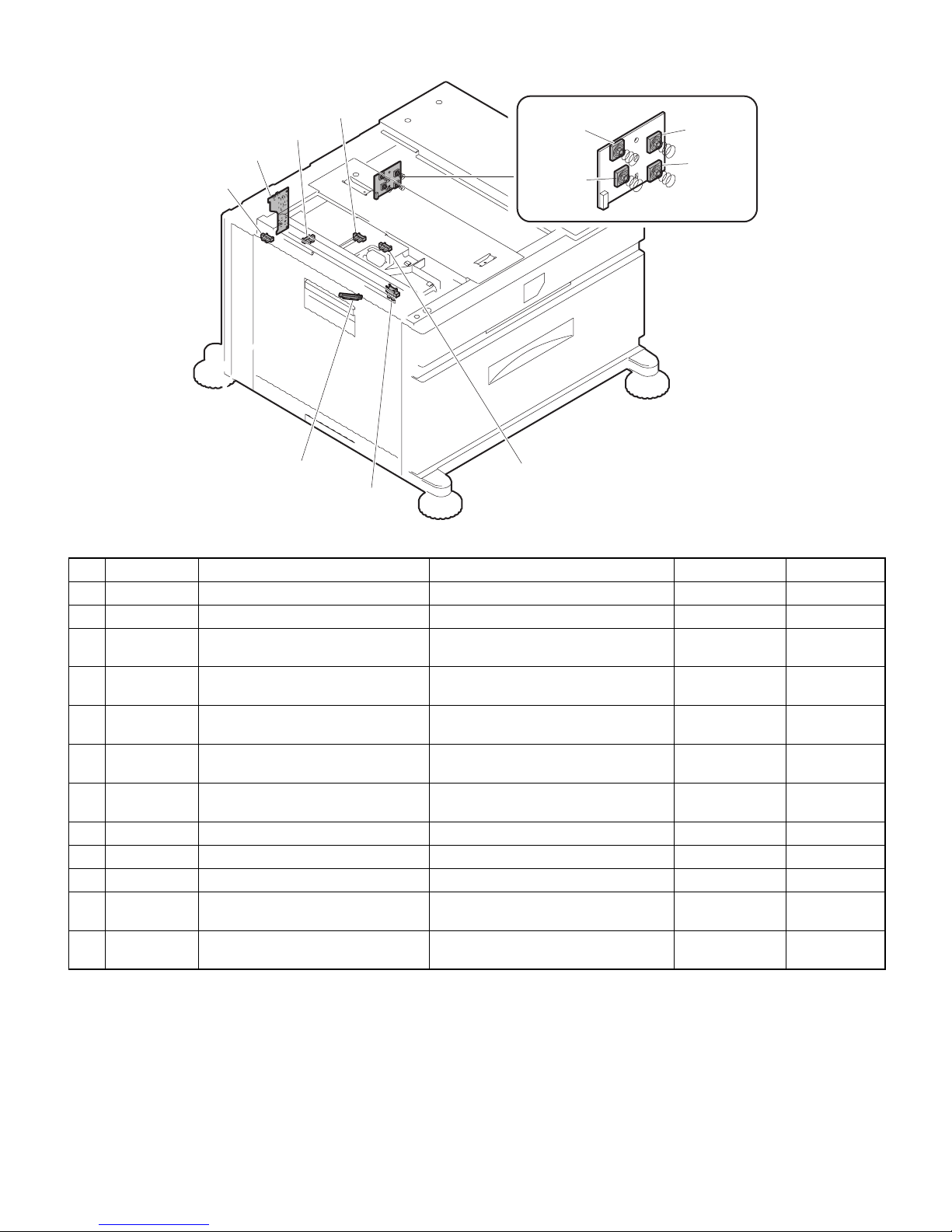
C. PWB, SENSOR
1.MCDRS
10.MCPWS
3.MCLUD
8.MCPED
2.MCSPD
12.MPTPWB
4.MCSS1
11.
5.MCSS2
7.MCSS4
6.MCSS3
9.MCPPD
No. Code Name Function Active condition Remark
1 MCDRS Side door open/close sensor Side door open/close detection H :Door closed
2 MCSPD MP tray remaining paper quantity sensor MP tray remaining paper quantity detection
3 MCLUD MP tray upper limit sensor MP tray upper limit detection H : Upper limit
detected
4 MCSS1 MP tray rear edge sensor 1 MP tray rear edge size detection L : When pressed In MP tray rear
edge size PWB
5 MCSS2 MP tray rear edge sensor 2 MP tray rear edge size detection L : When pressed In MP tray rear
edge size PWB
6 MCSS3 MP tray rear edge sensor 3 MP tray rear edge size detection L : When pressed In MP tray rear
edge size PWB
7 MCSS4 MP tray rear edge sensor 4 MP tray rear edge size detection L : When pressed In MP tray rear
edge size PWB
8 MCPED MP tray paper empty sensor MP tray paper empty detection L : Paper loaded
9 MCPPD MP transport sensor Detection of paper on the path L : Paper detected
10 MCPW S MP tray width sensor MP tray paper width detection Slide volume
11 MP tray rear
edge size PWB
MP tray rear edge size PWB Multi-purpose tray rear edge size detection
12 M PTPWB MPT PWB
Distributed the power supply from the main
unit.
Page 8
AR-D29 EXTERNAL VIEWS AND INTERNAL STRUCTURES
5 – 3
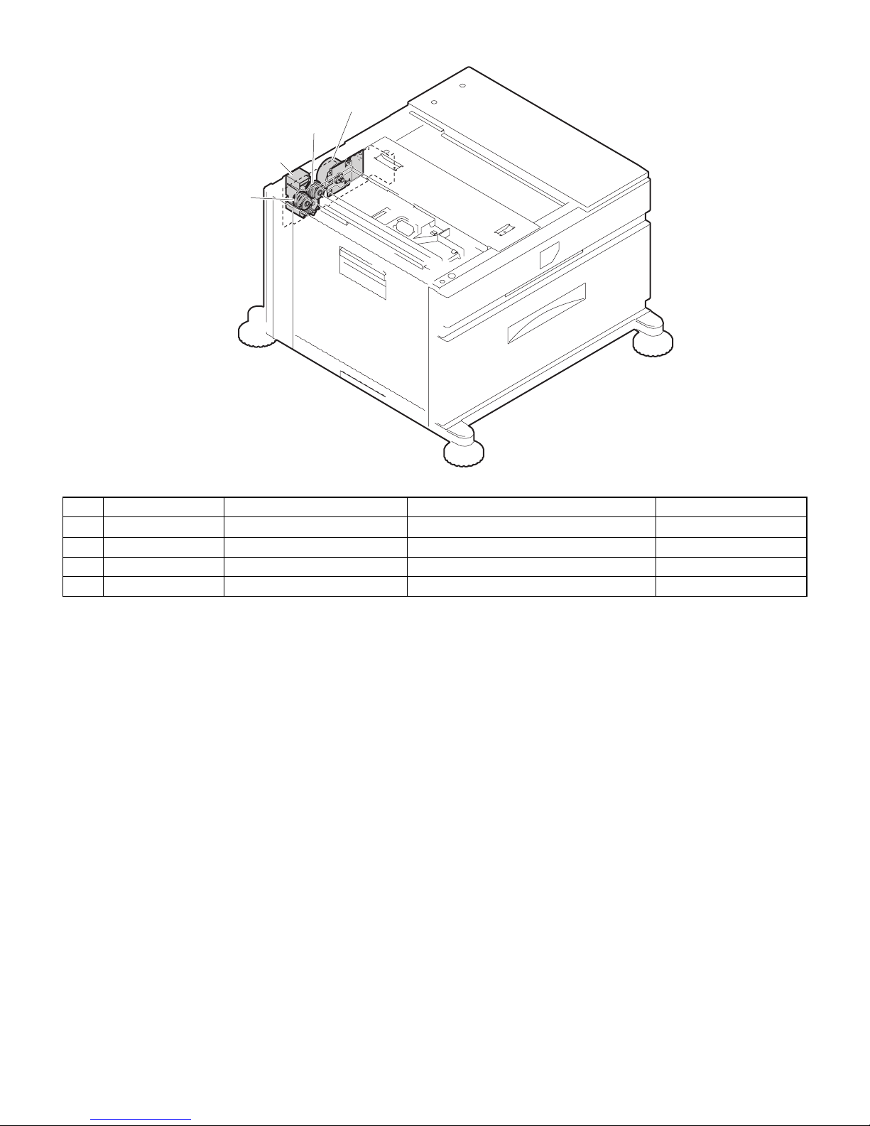
D. MOTOR, CLUTCH
2.MCLUM
3.MCPCL
4.MCM
1.MCFCL
No. Code Name Function Remark
1 MCFCL Multi-purpose transport clutch Clutch for transport from LCC desk
2 MCLUM Multi-purpose tray lift-up motor Multi-purpose tray lift-up
3 MCPCL Mult i-purpose paper feed clutch Clutch for paper feed from Multi-purpose tray
4 MCM Multi-purpose transport motor LCC desk paper transport
Page 9
AR-D29 ADJUSTMENTS
6 – 1
[6] ADJUSTMENTS
1. CHANGING THE PAPER SIZE
[Upper tray]
• A3 to A5R (11 x 7 to 5-1/2 x 8-1/2R) size plain paper can be set.
• Special paper can be set.
• Two maximum height lines are indicated: one for plain paper and one
for special paper.
Use the following procedure to change the size as needed.
1) Pull out paper tray.
If paper remains in the tray, remove it.
2) Adjust the guide plates A and B in the tray to the length and width of
the paper.
The guide plates A and B are slidable. Adjust them to the paper size
to be loaded while squeezing their lock levers.
3) Load paper into the tray.
Do not exceed red line when loading special paper to upper tray.
4) Gently push tray into the machine.
Push the tray firmly all the way into the machine.
5) Set the paper size.
Be sure to set the paper size and paper type referr ing to "2.Setting
the paper type and paper size".
If this is not done, paper misfeeds will occur.
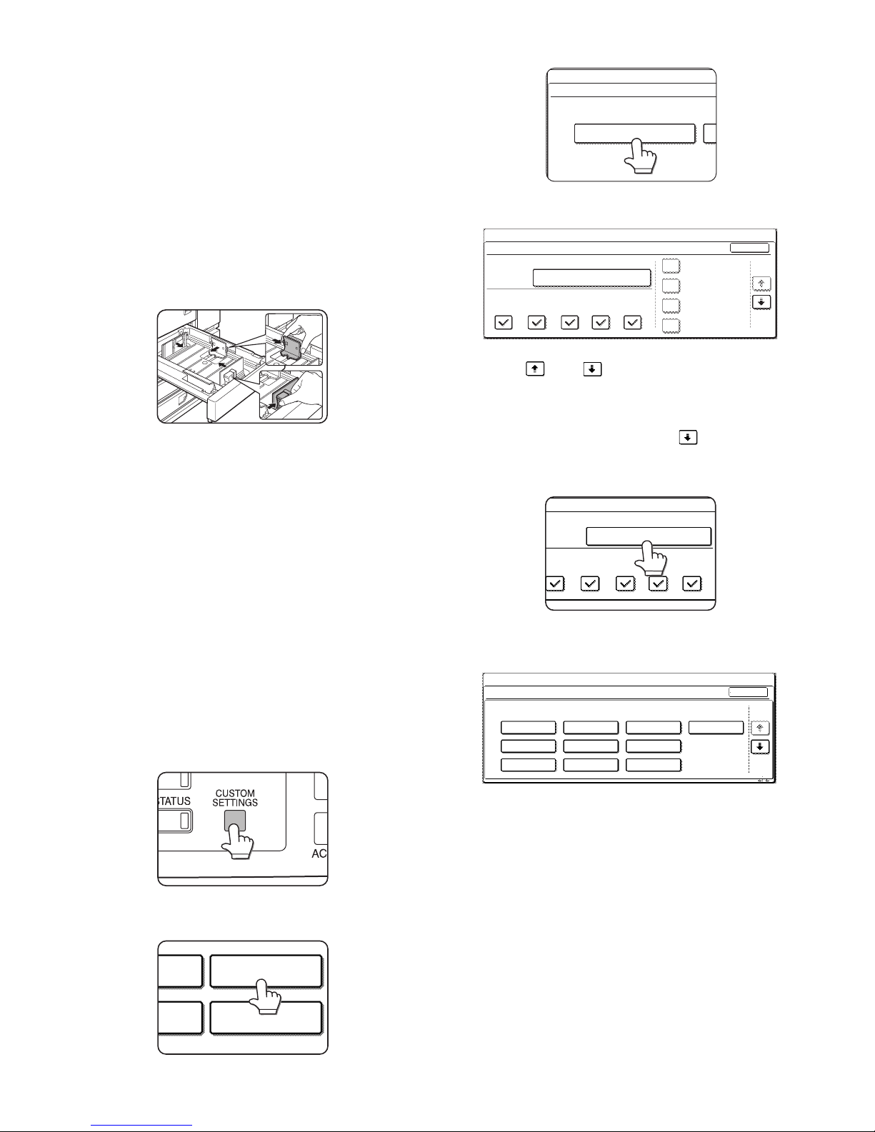
2. SETTING THE PAPER TYPE AND
PAPER SIZE
Follow these steps to change the paper type setting if the paper type is
changed in either paper tray. For the paper types that ca n be used in
each tray.
1) Press the [CUSTOM SETT INGS] key.
The custom setting menu screen will appear.
2) Touch the [PAPER TRAY SETTINGS] key.
The paper tray selection screen will appear.
3) Touch the [TRAY SETTINGS] key.
4) Display the setting screen of the desired paper tray.
Touch the key or key to display the setting screen of the
desired paper tray.
Note: To automatically switch to a tray with the same size and type of
paper (if there is one) in the event that the paper tray runs out of
paper, display the last screen with the key and select [AUTO
TRAY SWITCHING].
5) Touch the [TYPE/SIZE] key.
6) Select the type of paper that was loaded in the tray.
Example: The paper type of tray 2 is selected
Touch the desired paper type to select it.
The paper size setting screen will appear.
PAPER TRAY
SETTINGS
TA
PRINTER
CONDITION
TRAY SETTINGS
PAPER TRAY SETTINGS
CUSTOM SETTINGS
1/4
PLAIN / A4
OK
PRINT
PAPER TRAY SETTINGS
TYPE / SIZE
CUSTOM SETTINGS
TRAY 1
FAX
I-FAX
COPY
DOC.
FILING
FIXED PAPER SIDE
DISABLE DUPLEX
DISABLE STAPLE
DISABLE PUNCH
TYPE / SIZE
TRAY 2
PER TRAY SETTINGS
PRINT
COPY
I-FAX
DOC.
FILING
FAX
PLAIN / A4
CANCEL
1/2
PLAIN
RECYCLED
PRE-PRINTED PRE-PUNCHED
LETTER HEAD
COLOUR
HEAVY PAPER
ENVELOPE
LABELS
TRANSPARENCY
TRAY 2 TYPE/SIZE SETTING
SELECT THE PAPER TYPE.
CUSTOM SETTINGS
1/2
Page 10
AR-D29 DISASSEMBLY AND ASSEMBLY, MAINTENANCE
7 – 1
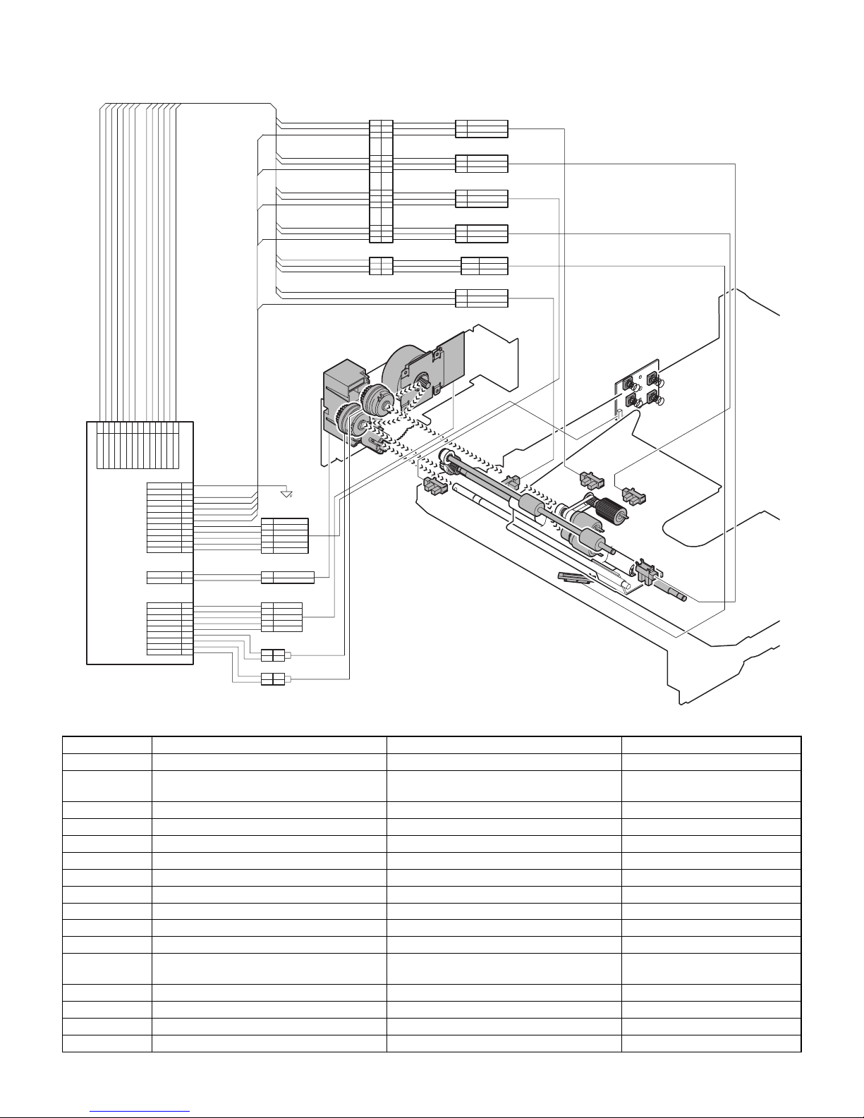
[7] DISASSEMBLY AND ASSEMBLY, MAINTENANCE
A. MAJOR PARTS AND SIGNAL FUNCTIONS
Code Name Function R e mark
MCDRS MP door open / close sensor MP left door open / close detection
Control PWB Control PWB Communication with the machine,
machine operation control
MCSPD MP tray remaining paper quantity sensor MP tray remaining paper quantity detection
MCLUD MP tray upper limit sensor MP tray upper limit detection
MDSS1 MP tray rear edge sensor 1 MP tray rear edge size detection In MP tray rear edge size PWB
MCSS2 MP tray rear edge sensor 2 MP tray rear edge size detection In MP tray rear edge size PWB
MCSS3 MP tray rear edge sensor 3 MP tray rear edge size detection In MP tray rear edge size PWB
MCSS4 MP tray rear edge sensor 4 MP tray rear edge size detection In MP tray rear edge size PWB
MCPED MP tray paper empty sens or MP tray paper empty detection
MCPPD MP transport sensor Detection of paper on the path
MCPWS MP tray width sensor MP tray paper width detection Slide volume
MP tray rear
edge size PWB
MP tray rear edge size PWB MP tray rear edge size detection
MCFCL Multi-purpose tray transport clutch Multi-purpose tray transport clutch
MCLUM Multi-purpose tray lift-up motor Multi-purpose tray lift-up
MCPCL Multi-purpose paper feed clutch Clutch for paper feed from Multi-purpose tray
MCM Multi-purpose tray transport motor Multi-purpose tray paper transport
MCM
MCM
MCM
MCDRS
MCSPD
MCSPD
MCSPD
MCLUD
MCPED
MCSS2
MCSS4
MCSS1
MCSS3
MCSS3
MCSS3
MCPPD
MCPWS
MCPWS
MCPWS
MCLUM
MCLUM
MCLUM
MCFCL
MCFCL
MCFCL
MCPCL
MCPCL
MCPCL
MPT LD PWB
MPT PWB
12
4
71151036192
8
+5V
MCPWS
+5V
MCPPD
+5V
CN-E
+5V
VAREF
MCPED
N.C.
MCPWS2
MCLUD
14
13
+5V
MCDRS
MCSPD
PHDR-14VS-1
3
1
2
5
MCSS2
8
MCSS1
6
4
7
9
10
GND2
GND2
GND2
CN-F
MCSS3
MCSS41112
GND2
GND2
GND2
GND2
GND2
PHDR-12VS-1
24V
1
MCLUM/
2
PHR-2
MCPCL/
+24V
MCFCL/
+24V
3
1
MCM/
GND1
+24V
MCM-T
2
5
4
MCMCLK/
6
7
8
9
PHR-9
11
22
11
22
SMR-02V-B
SMR-02V-NSMP-02V-NC
SMP-02V-BC
SRA-21T-4
MCLUM/
24V
MCSS2
MCSS3
MCSS4
N.C.
MCSS1
GND2
PHR-6
PHR-2
5
2
6
4
3
1
MCMCLK/
MCM/
4
GND1
3
1
MCM-T
5
+24V
2
PHR-5
13
14
17
18
15
16
18
15
13
16
17
14
SMP-03V-BC SMR-03V-B
GND2
1
MCLUD
MCPPD
2
2
+5V
3
+5V
3
GND2
1
1
2
3 GND2
MCSPD
+5V
2
1
CN-D
CN-A
8
4
5
8
696
9
7
5
4
7
SMR-18V-BSMP-18V-BC
3
212
3
1
GND23
GND23
MCPED
+5V
1
MCDRS
1
2
+5V
2
3T
MCPWS2
MCPWS
VAREF
2T
1T
Page 11
AR-D29 DISASSEMBLY AND ASSEMBLY, MAINTENANCE
7 – 2
B. MAINTENANCE LIST
(1) MAINTENANCE LIST
*
1:Replacement reference: Use the counter value of each paper feed port as the replacement reference.
Paper feed section pickup roller, paper feed roller: 100K or 1 year
u
Check (Clean, replace, or adjust as necessary.)
F
Clean
b
Replace
v
Adjust , Lubricate
k
Move position
Unit name
No.
Part name
When
calling
100K 200K 300K 400K Remark
Paper feed separation section 1 Paper feed rollers
uuuuu*
1
Transport section 2 Transport rollers
u
FFFF
Drive section 3 Gears
u
,,,,(Specified position)
4Belts
uuuuu
Other 5 Sensors
uuuuu
4
5
5
1
3
5
1
5
2
4
Page 12

AR-D29 DISASSEMBLY AND ASSEMBLY, MAINTENANCE
7 – 3
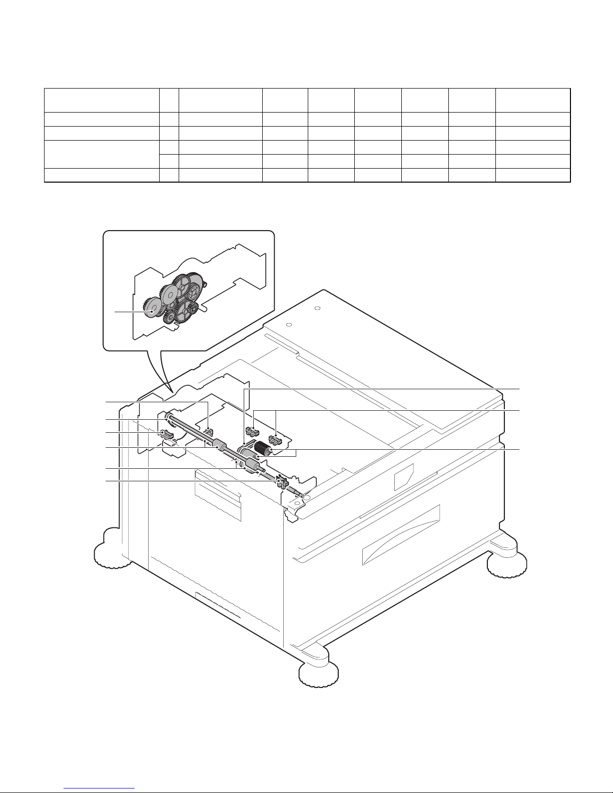
(2) MAINTENANCE AND PARTS REPLACEMENT
(List of Replacement Parts)
a. Paper feed unit
1) Pull out the multi-purpose tray.
First, pull out the right side of the tray, and then pull out the left side.
2) Remove the left door.
3) Remove the multi-purpose paper feed unit.
a-1. Pick up roller
a-2. Paper feed roller
a-3. Separate roller
a-4. Torque limiter
1) Pull out the multi-purpose tray.
2) Remove the paper guide.
No. Unit Parts
a Paper feed unit 1 Pick up roller
b
2 Paper feed roller
b
3 Separate roller
b
4 Torque limiter
u
5Belts
u
6 Upper limit sensor
u
7 Paper empty sensor
u
8 Paper transport sensor
u
9 Side door open/close sensor
u
10 Transfer rollers
u
b Multi-purpose
drive unit
1 Gears
u
,
c Other 1 Rear edge size PWB
2 Remaining paper quantity sensor
u
a-1
a-8
c-1
a-2
a-7
a-6
a-10
a-9
a-4
a-5
c-2
a
a-10
a-5
a-3
b-1
b
1)
2)
2)
1)
6)
4)
5)
4)
1)
2)
3)
1)
Page 13

AR-D29 DISASSEMBLY AND ASSEMBLY, MAINTENANCE
7 – 4
3) Disengage the roller hook, and remove the roller.
*
When installing the roller, check to ensure that the hook is securely
engaged in the groove.
4) After removing the roller, remove the torque limiter.
*
When installing the torque limiter, check to ensure that the pin is
fully inserted into the torque limiter groove.
a-5. Belts
1) Remove the paper feed unit.
2) Remove the pickup roller and paper feed roller.
a-6. Upper limit sensor
a-7. Paper empty sensor
a-8. Paper transport sensor
a-9. Side door open/close sensor
1) Remove the paper feed unit.
a-10. Transfer rollers
1) Remove the paper feed unit.
a
1)
b
a
a
a
1)
1)
1)
1)
2)
3)
4)
3)
3)
4)
4)
a
a
b
b
a
b
Page 14

AR-D29 DISASSEMBLY AND ASSEMBLY, MAINTENANCE
7 – 5
b. Multi-purpose drive unit
1) Remove the rear cabinet.
2) Remove the multi-purpose tray drive section.
b-1. Gears
1) Remove the multi-purpose tray drive section.
c-1. Rear edge size PWB
c-2. Remaining paper quantity sensor
1) Remove the rear cabinet.
2) Remove the control PWB and the sensors.
2)
1)
1)
3)
2)
2)
1)
2)
1)
1)
a
a
2)
2)
1)
1)
Page 15

AR-D29 BLOCK DIAGRAM, WIRING DIAGRAM,CIRCUIT DIAGRAM, PARTS ARRANGEMENT
8 – 1
[8] BLOCK DIAGRAM, WIRING DIAGRAM,CIRCUIT DIAGRAM, PARTS ARRANGEMENT
A. BLOCK DIAGRAM
A
B
C
D
87654
3
21
12345678
D
C
B
A A
B
C
D
87654
3
21
12345678
D
C
B
A A
B
C
D
87654
3
21
12345678
D
C
B
A A
B
C
D
87654
3
21
12345678
D
C
B
A
1/1
MCDRS
VD/S-GND
P
R
I
NTER
MAL
TI
CS UNI T
+5V1(VD)
GND2(
P
-GND)
M
C
F
C
L/
M
C
LU
M/
M
C
PCL
/
Multi PWB
+
2
4V2(
V
B
)
VA
R
EF
M
CPP
D
MC
D
R
S
MCPED
MC
L
UD
M
CP
WS
M
CP
WS
MCDR
S
M
CPPD
VD/S-GND
VD/S-GND
M
CLUD
D
C
P
R
/
MCSPD
MCS
E
T
MC
S
S
1
M
C
S
S2
M
CSS3MCSS
4
GND1
(
S-
G
ND
)
MC
M
-T
MCMCL
K
/
M
C
M/
M
CPPD
MCLUD
MCSP
D
VD/S-GND
VD/S-GND
MCP
E
D
M
CSPDMC
PE
D
S-GND
MCSS
1
M
CSS1
S-GND
MCSS2
M
C
S
S2
S-GND
MCS
S
3
MCS
S
3
M
CSS
4
MC
SS
4
S-GND
M
C
PW
S
VAREF
M
C
F
C
L
/
DCPR
/
VB
M
CM
C
L
K
/
MC
FCL/
M
CP
C
L
/
MCM
MCM
-T
VB
M
CLU
M
/
M
CM
/
M
CPCL
/
P-GND
VB/P-GND
MC
L
U
M
/
DH MPF
D
H
PWB
A
C
L
AC N
AC
N
A
C
L
M
CSET
M
C
S
E
T
S-GND
OPTIO
N
AL
Y
VB
DH-SW
Page 16

AR-D29 BLOCK DIAGRAM, WIRING DIAGRAM,CIRCUIT DIAGRAM, PARTS ARRANGEMENT
8 – 2
B. WIRING DIAGRAM
A
B
C
D
87654
3
21
12
3
456
7
8
D
C
B
A
A
B
C
D
87654
3
21
12
3
456
7
8
D
C
B
A
A
B
C
D
87654
3
21
12
3
456
7
8
D
C
B
A
A
B
C
D
87654
3
21
12
3
456
7
8
D
C
B
A
1/1
AC
L1
2N.C
15
12
9
6
3
17
14
11
8
5
2
16
13
10
7
4
1
181920
24
23
22
21
GND1
+5V
GND2
VAREF
MCPPD
MCDRS
MCPED
MCLUD
MCPWS
MCSS4
MCSS1
MCSS2
MCSS3
MCSPD
MCSET
MCPCL/
MCFCL/
MCLUM/
MCM-T
MCMCLK/
MCM/
e/?
DCPR/
12
MCSS4
4
17
MCPCL/
11
MP
T
P
W
B
3
MCMCLK/
GND1
1
5
7
MCPED
MCPCL/
16
11
MCSS3
5
10
MCSET4MCM-T
24
18
12
MCPCL
N.C
MCDRS
+24V
22
20
6
10
MCSS2
3
3
MCSPD
2
14
MCLUM/
VAREF
6
8
MCSS1
MCPPD
1
2
9
MCPWS
MCFCL/
13
DCPR/
2
7
MCFCL/
+5V
1
15
MCFCL
MCM/
GND2
23
19
9
8
MCLUD
+24V
21
2
1
MCLUM
LIFT MOTOR UNIT
3
DCPR/
+24V2
1
N.C
2
1
GND1
MCLUM
+24V
+24V
11221
122
5
MCSS2
8
MCSS1
647
9
10
+5V
MCPWS
+5V
MCPPD
+5V
GND2
MCLUM1GND1
2
MCMCLK/
MCM/
4
GND1
3
1
MCM
MCM-T
5
+24V
2
3
1
MCM/
GND1
+24V
MCM-T
254
MCMCLK/
6
789
+24V
DCPR/
+5V
VAREF
MCPED
N.C.
MCPWS2
GND2
GND2
MCLUD
14
13
+5V
MCDRS
MCSS3
MCSS4
11
12
GND1
GND2
GND2
GND2
GND2
MPT LD PWB
5
2
6
MCSS24MCSS33MCSS4
1
N.C.
MCSS1
GND2
8
4
GND2
13
5
MCDRS
3
8
1
2
GND2
1
14
3
MCLUD
3
MCPPD
17
GND2
MCSPD
2
18
6
MCSPD
MCPED
9
+5V
3T
+5V
1
6
MCPWS2
MCDRS
2
9
MCLUD
1
+5V
15
MCPWS
MCPPD
16
18
VAREF
3
7
5
2T
+5V
15
4
PAPER FEEDING UNIT
2
7
MPT VR UN
MCPED
3
13
1T
+5V
2
GND2
16
1
17
14
321
2
3
1
GND2
PHDR-24VS-1
MCSPD
PHDR-14VS-1
PHDR-12VS-1
PHR-2
SMR-18V-B
SMP-18V-BC
SMP-03V-BC SMR-03V-B
PHR-6
PHR-2
PHR-5
PHR-9
SMR-02V-B
SMR-02V-NSMP-02V-NC
SMP-02V-BC
PHR-3
SRA-21T-4
1
1
2
2
ELR-02VF
AC N 3
2
AC N
AC
L
1
3
N.C
PHR-3
B2P3-VH
B2P3-VH
C
N
-
B
C
N-C
C
N
-
A
N.C
3
D
H
P
W
B
ELP-02
DH
M
P
F
TIG
ER
MAIN UN
ELP-04NV
RES_FIN1
RXD_FIN2/
2
4
TXD_DSK
GND2
2
(N.C)
2
GND
19
14
ELR-02VF
B22B-PADRS
RES_DSK
1
3
GND
13
3
2
RXD_DSK
18
5
GND2
4
PADP-22V-1-R
2
RXD_FIN1/
+24V4
+5V2
TXD_FIN1
TXD_FIN2
15
8
D
C
P
S
RES_FIN2
10
3
TRC_DSK/
11
7
DTR_FIN2/
ELP-02V
1
16
DTR_FIN1/
4
DSR_FIN1/
1
1
2
5
DTR_DSK
17
9
6
1
4
DSR_FIN2/
12
ELR-04V
CN1
1
FGS_FIN/
3
1
GND
21
20
(N.C)
(N.C)
DSR_DSK
22
RXD-DSK/
6
9
RES-DSK
1
GND24DSR-DSK/
7
10
TRC-DSK
P-GND2TXD-DSK
5
8
DTR-DSK/
11
S-GND
3
VD(+5V)
+24V(VB)
C
N
1
0
B24B-PADES PADP-24V-1-E
FUS
E
P
W
B
DH-SW
C
N
-
B
C
N
-
C
C
N
-
F
CN-
E
C
N
-
D
C
N
-
A
POWERSUPPLY I/F UN
OPTION
(OPTION FOR JAPAN)
(OPTION FOR JAPAN)
Page 17

AR-D29 BLOCK DIAGRAM, WIRING DIAGRAM,CIRCUIT DIAGRAM, PARTS ARRANGEMENT
8 – 3
C. CIRCUIT DIAGRAM
A
B
C
D
87654
3
21
12345678
D
C
B
A A
B
C
D
87654
3
21
12345678
D
C
B
A A
B
C
D
87654
3
21
12345678
D
C
B
A A
B
C
D
87654
3
21
12345678
D
C
B
A
1/1
MPT PWB
M
CND-2
VD
VB
VB
CNC-1
+5V1
CNC-2
VAREF
CNC-3
+24V2
CNC-4
GND1
CNC-5
GND2
CNC-6
MCPPD
CNC-7
MCDRS
CNC-8
MCPED
CNC-9
MCLUD
CNC-10
MCPWS
CNC-12
MCSS2
CNC-13
MCSS3
CNC-14
MCSS4
CNC-24
DCPR/
CNC-15
MCSPD
CNC-16
MCS
E
T
CNC-17
MCPCL/
CNC-18
MCFCL/
CNC-19
MCLUM/
CNC-20
MCM-T
CNC-21
MCMCLK/
CNC-22
MCM/
CNC-11
MCSS1
CND-9
MCPCL/
CND-7
MCFCL/
CNE-9
MCPWS
CNE-6
VAREF
CNE-13
MCLUD
CNE-12
MCPED
CNE-10
MCPPD
CNA-2
GND1
CND-3
MCM/
CND-4
MCM-T
CNF-1,3,4,5,6,7,8
GND2
CNE-14
MCSPD
CNB-2
DCPR/
CNF-12
MCSS4
CNF-11
MCSS3
CNF-10
MCSS2
CND-5
MCMCLK/
CNE-11
MCDRS
CNF-9
MCSS1
C004
223Z/50V
C003
47u/35V
+
C002
223Z/50V
C001
47u/35V
+
C005
47u/35V
+
C006
223Z/50V
CNE-1,2,3,4,5
+5V1
CND-1,6,8
CNB-1
+24V
2
JP001
GND
CNC-23
N.C
CNE-8
MCPWS2
CND-2
R002
2.4kJ1/2W
TR001
2SB1240
2.4kJ1/4W
R001
2.4kJ1/2W
R004
TR002
2SB1240
2.4kJ1/4W
R003
D001
DSM1D
CNF-2
D003
1SS133
D002
1SS133
ICP001
ICP-N20
JP002
(MCLUM)
CNA-1
MCLUM
Parts View
CN-A
CN-B
CN-D
CN-C
CN-E
CN-F
CN-A
CN-C
CN-D
CN-E
CN-F
CN-B
(JST:B2B-PH-K-S)
(JST:B3B-PH-K-S)
231
1
DCPR/
+24V2
N.C
MCLUM2GND1
(JST:B24B-PHDSS-B)
1
2
468
10
12
1416182022
24
3
579111315171921
23
+5V1
+24V2
GND2
MCDRS
MCLUD
MCSS1
MCSS3
MCSPD
MCPCL/
MCLUM/
MCMCLK/
N.C
VAREF
GND1
MCPPD
MCPED
MCPWS
MCSS2
MCSS4
MCSET
MCFCL/
MCM-T
MCM/
DCPR/
(JST:B9B-PH-K-S)
1
2
3
4
5
6
7
8
9
+24V2
GND1
MCM/
MCM-T
MCMCLK/
+24V2
MCFCL/
+24V2
MCPCL/
(JST:B14B-PHDSS-B)
1
3
579
11
13
2468101214
+5V1
+5V1
+5V1
+5V1
+5V1
VAREF
MCPWS2
MCPPD
MCPED
MCSPD
N.C
MCPWS
MCDRS
MCLUD
(JST:B12B-PHDSS-B)
13579
11
2
468
10
12
GND2
GND2
GND2
GND2 GND2
GND2
GND2
GND2
MCSS1
MCSS3
MCSS2
MCSS4
Page 18

AR-D29 BLOCK DIAGRAM, WIRING DIAGRAM,CIRCUIT DIAGRAM, PARTS ARRANGEMENT
8 – 4
D. PARTS ARRANGEMENT
■ CONTROL PWB
Page 19

q
PARTS GUIDE
CONTENTS
1
Exteriors
2
Left door
3
Frame 1
4
Frame 2
5
Tandem cassette
6
Multi paper feed
7
Multi drive
8
500 cassette[Multi purpose]
MODEL
AR-D29
9
Packing Material & Accessories
■
Index
Page 20

DEFINITION
The definition of each Rank is as follows and also noted in the list
Rank A : Maintenance parts, and consumable parts which are not included in but closely related to maintenance parts
Rank B : Performance/function parts (sensors, clutches, and other electrical parts), consumable parts
Rank E : Unit parts including PWB
Rank D : Preparation parts (External fitting, packing, parts packed together)
Rank C : Parts other than the above (excluding sub components of PWB)
Because parts marked with "!" is indispensable for the machine safety maintenance and operation, it must be replaced with
the parts specific to the product specification.
F Other than this Parts Guide, please refer to documents Service Manual(including Circuit Diagram)of this model.
F Please use the 13 digit code described in the right hand corner of front cover of the document, when you place an order.
F For U.S. only-Use order codes provided in advertising literature. Do not order from parts department.
Exteriors
1
PRICE
NEW
NO. PARTS CODE
1 GCAB-0953FCN2 BM D Top side cabinet
2 XHBS740P10000 AA C Screw(4×10)
4 XHBS740P06000 AA C Screw(4×6)
5 GCAB-0955FCN2 BR D Desk right cabinet
6 PCOVP1796FCNZ AQ D Adjuster cover N
7 GCAB-0975FCN3 BD D Desk front lower cabinet
8 GCAB-0954FCN1 AY D Tandem left front cabinet
9 GCAB-0958FCN2 BA D Desk left lower cabinet
10 GCAB-0957FCN1 BA D Desk left rear cabinet
11 GCAB-0974FCN1 AY D Desk side rear cabinet
12 GCAB-0956FCN5 BU D Desk rear cabinet
13 PCOVP1586FCNZ AR D AC inlet cover
14 XEBS730P10000 AC C Screw(3×10)
RANK
MARK
PART
RANK
DESCRIPTION
Left door
2
PRICE
NEW
NO. PARTS CODE
1 GDOR-0033FCNZ BP D Desk left door
3 NSFTZ2635FCZZ AX C Desk left door lock shaft
4 PTME-0284FCZZ AE C Desk left door lock pawl
5 LX-BZ3006SC0M AA C Screw(3×6)
6 MLEVP0818FCN3 AN C Desk left door cancellation lever
10 XEBS740P12000 AA C Screw(4×12)
11 XWHSD40-08120 AA C Washer
12 MSPRC2916FCZZ AC C Desk left door lock spring
13 PGIDM1944FCZ1 BH D Desk left door PG
RANK
MARK
PART
RANK
DESCRIPTION
– 1 –
Page 21

1
Exteriors
2
14
12
2
11
2
2
10
2
2
2
9
13
2
11
2
2
8
2
2
7
1
4
2
5
2
2
6
2
2
Left door
1
2
10
13
6
10
12
2
2
10
11
5
4
3
5
6
5
FCP08831
10
10
10
11
10
4
10
FCP08832
– 2 –
Page 22

Frame 1
3
PRICE
NEW
NO. PARTS CODE
1 LPLTM5958FCZZ AD C U turn PG fulcrum plate 1
2 XHBS740P08000 AA C Screw(4×8)
4 JHNDM0179FCZZ AZ D Handle base plate
5 LRALM0190FCZ1 BG C Cassette rail R
6 PCLR-0441FCZZ AK C Roller(φ16)
7 LX-BZ0926FCZ1 AD C Screw
10 LSTYM0270FCZZ BG C Top side stay
11 XHBS740P06000 AA C Screw(4×6)
15 LRALM0191FCZ1 BL C Slide rail
18 LHLDZ1466FCZ1 AG C Desk left door fulcrum
19 XHBS740P08000 AA C Screw(4×8)
23 NSFTZ2852FCZ1 AH C Adjuster D
24 PAJS-0017FCZZ AG C Adjuster wheel(φ50)
25 LX-BZ0769FCZZ AC C Step screw H
26 GLEGG0075FCZZ AE C Rubber foot
27 GLEGP0076FCZ1 AS D Caster
28 LBRC-0065FCZZ AN C Left adjuster fixing bracket
29 PCOVP1588FCN1 AX D Left adjuster cover
30 CSTYM0287FC01 BN C Left adjuster stay Assy
31 XEBS740P12000 AA C Screw(4×12)
32 LRALM0189FCZ2 BG C Cassette rail L
33 MSPRT2893FCZZ AD C Width detect spring
34 LDAIU0631FCZZ AX D Width detect fixing base
35 PCASZ0293FCZ2 AZ D Width detect case bottom
37 MARMP0267FCZ1 AF C Width detect arm
38 XEBS720P06000 AC C Screw(2×6)
39 DHAI-3267FCPZ AG C MPT width detect slide resistance harness
46 LSTYM0271FCZZ AD C Paper feed support plate F
47 LX-BZ0930FCZZ AC C Screw(4×6)
48 PCOVP1819FCNZ AM C Handle cover
49 LX-BZ0728FCZ1 AC C Screw(3×8)
50 LX-BZ0957FCZZ AC C Screw(4×18)
51 XWHSD40-08100 AA C Washer
52 XBBS740P08000 AA C Screw(4×8)
53 LPLTM6474FCZZ AV C Handle support plate
54 PCOVP1890FCZZ BT N C Left tarnster cover
55 LSTPP0355FCZZ AD C Desk left door stopper
56 LPLTM5830FCZZ AP C Vertical transfer fixing plate R
RANK
MARK
PART
RANK
DESCRIPTION
– 3 –
Page 23

3
Frame 1
46
2
49
15
49
51
50
50
7
51
5
2
6
48
2
4
49
2
2
10
11
2
48
4
2
2
53
11
2
2
2
2
2
2
18
47
39
38
35
32
37
56
2
1919
2
2
7
6
2
34
2
19
56
33
15
19
2
2
52
2
11
2
1
2
18
19
54
2
19
55
23
24
29
23
24
26
25
30
31
26
25
49
24
2
2
25
2
27
47
2
27
2
47
23
24
26
25
27
2
2
23
24
26
2
25
FCP08833
23
26
2
4
49
49
2
48
2
2
28
27
2
2
– 4 –
Page 24

Frame 2
4
PRICE
NEW
NO. PARTS CODE
1 XHBS740P08000 AA C Screw(4×8)
2 CFRM-1041FC33 BF E Multi desk drive unit
3 CPWBF1592FCE1 AN E MPT vertical detect PWB
4 QSW-M0131FCZZ AC B Push switch
5 MSPRC2894FCZZ AC C Vertical detect switch spring
6 QCNCM0542FCZZ AC C Connector(S6B-PH-K-S)
7 LHLDZ1464FCZZ AG C Vertical detect spring holder
8 LHLDZ1463FCZZ AX C Vertical detect holder
9 XHBS740P10000 AA C Screw(4×10)
10 LPLTP5808FCZZ AF C Multi cassette lock plate
11 MSPRD2987FCZZ AD C T cassette earth spring
12 PCOVP1577FCZ1 AV D Multi remainder detect cover
13 VHPGP1A73A+-1 AG B Photo sensor(GP1A73A)
14 DHAI-3271FCPZ BA C MPT paper feed interface harness N
15 LX-BZ0927FCZZ AG C Body position decide step screw
16 LBSHC0350FCZZ AF C Edge holder(EH-18)
17 PCOVP1576FCZZ AP D Multi paper feed drive cover
18 XRESP50-06000 AA C E type ring(E5)
19 NROLP0896FCZZ AC C Transfer follower roller
20 NSFTZ2631FCZZ AE C T cassette lock shaft
Frame 2
4
RANK
MARK
PART
RANK
1
2
DESCRIPTION
14
3
4
1
6
20
19
18
17
15
16
1
13
1
15
5
7
4
7
8
9
10
9
11
1
FCP08834
10
1
9
12
– 5 –
Page 25

Tandem cassette
5
PRICE
NEW
NO. PARTS CODE
1 XHBS740P08000 AA C Screw(4×8)
2 CPLTM6666FC01 CE N C Cassette case
3 XHBS740P10000 AA C Screw(4×10)
4 XWHSD40-08120 AA C Washer
5 XEBS740P12000 AA C Screw(4×12)
6 PCOVP1609FCZ1 AP D Tandem knob cover
7 GCAB-0959FCN2 BS D Tandem front cabinet
8 XRESP50-06000 AA C E type ring(E5)
9 MSPRD2909FCZZ AG C T cassette lock arm spring
10 MARMP0270FCZZ AK C T cassette lock arm
11 NSFTZ2631FCZZ AE C T cassette lock shaft
Tandem cassette
5
RANK
MARK
PART
RANK
DESCRIPTION
11
2
10
9
8
3
5
1
4
3
1
4
1
3
3
4
5
3
4
4
4
3
1
5
6
5
7
FCP08835
– 6 –
Page 26

Multi paper feed
6
PRICE
NEW
NO. PARTS CODE
1 LPLTM5825FCZZ AQ C Paper feed PG upper support plate
2 XEBS740P12000 AA C Screw(4×12)
3 XHBS740P10000 AA C Screw(4×10)
4 NROLR1336FCZZ AU B Transfer roller 2
5 NBRGM0096FCZ1 AC C Bearing(φ6 WD)
6 XRESP50-06000 AA C E type ring(E5)
7 XEBS730P08000 AC C Screw(3×8)
8 LPLTP5827FCZZ AF C Multi sensor fixing plate
9 VHPGP1A73A+-1 AG B Photo sensor(GP1A73A)
10 DHAI-3250FCPZ AW C MPT paper feed harness
11 MSPRC2965FCZZ AB C Pick up roller earth spring
12 MLEVP0813FCZ2 AH C Multi PE actuator
13 PGIDM1912FCZ1 AW C Paper feed paper guide F
14 XHBS740P10000 AA C Screw(4×10)
15 MLEVP0812FCZ1 AG C Multi transfer actuator
16 MSPRD2900FCZZ AC C Multi transfer actuator spring
17 PGIDM1911FCZ2 BF D Multi paper feed paper guide upper
18 MLEVP0814FCZ1 AK C Pick up move lever
19 MSPRD2903FCZZ AC C Pick up move lever spring
20 LPLTM5824FCZZ AH C Paper feed roller fixing plate
21 LPINS0165FCZZ AB C Pin(2×8)
22 NBLTH0337FCZZ AK B Belt(S2M102)
23 LPINS0133FCZZ AA C Pin(2×10)
24 NGERH1406FCZZ AG C Gear(18/22P)
25 NGERH0863FCZZ AB C Pick up roller gear(18T)
26 PCLR-0470FCZZ AE C Drive joint collar
28 XRESP70-08000 AA C E type ring(E7)
29 NROLP1364FCZZ AC C Transfer roller M
30 NROLR1335FCZ1 AQ B Transfer roller 1
31 MSPRT2902FCZ1 AC C Multi pick pressure spring
32 NSFTZ2620FCZZ AP C Pick up roller shaft
33 NPLYZ0365FCZZ AC C Pick up roller pulley
34 NBLTH0338FCZZ AH B Belt(B55MXL)
35 NROLR1509FCZZ AX A Pick up roller
36 NROLR1508FCZZ AX B Paper feed separate roller
37 NCPL-0049FCZZ AH C Oneway coupling
38 NSFTZ2621FCZZ AN C Multi transfer follower shaft 2
39 NSFTZ2619FCZ1 AX C Multi paper feed roller shaft
40 PGIDM1914FCZ1 BA D Multi paper feed lower PG
41 NSFTZ2623FCZZ AT C Transfer follower shaft
42 PCLC-0305FCZZ AV B Torque limiter multi
43 LPINS0089FCZZ AA C SP pin(2×8)
44 LX-WZ2011SCZZ AA C Washer
45 MSPRC2905FCZ1 AC C Transfer follower spring 1
46 MLEVP0834FCZ1 AF C Multi separate lever
47 MSPRC2904FCZ2 AC C Multi pressure spring
48 MARMP0269FCZZ AE C Multi separate roller arm
49 PGIDM1915FCZ1 AZ D Multi U turn paper guide
50 LPLTM5826FCZZ AM C Paper feed under PG support plate
55 NCPL-0049FCBZ AT C Multi separate coupling(with oneway)
56 NSFTZ2622FCZ2 AX C Multi separation roller shaft
57 NROLP0896FCZZ AC C Transfer follower roller
58 PGIDM1913FCZ1 AV C Multi paper exit paper guide
59 XRESP40-06000 AA C E type ring(E4)
60 MSPRT2901FCZ1 AC C Multi transfer follower spring 2
61 LHLDZ1465FCZ2 AP C Pick up roller holder
62 NPLYZ0378FCZZ AF C Pulley(22P S2M)
63 MSPRT2973FCZZ AD C Multi separate pressure spring
64 NPLYZ0373FCZZ AH C Paper feed roller pulley
66 LPLTM5958FCZZ AD C U turn PG fulcrum plate 1
67 XHBS740P08000 AA C Screw(4×8)
RANK
MARK
PART
RANK
DESCRIPTION
– 7 –
Page 27

Multi paper feed
6
3
2
1
2
2
21
60
26
44
23
5
6
5
10
9
5
59
2
28
2
20
A
B
14
29
30
58
57
18
17
59
A
5
19
10
16
29
28
6
5
4
7
9
6
8
11
31
14
61
5
12
15
10
5
6
7
8
9
8
7
9
10
5
6
32
64
33
34
2
13
35
6
25
24
21
6
22
62
FCP08836
41
57
60
49
67
B
66
2
– 8 –
40
6
55
6
48
47
46
2
3
63
2
45
57
39
38
50
37
36
56
44
6
43
42
36
2
2
Page 28

Multi drive
7
PRICE
NEW
NO. PARTS CODE
1 DHAI-3218FCPZ AZ C MPT body interface harness
2 CFRM-1041FC01 AU C Multi drive frame 1 Assy
3 RMOTP0868FCZZ BP B Transfer motor C
4 DHAI-3269FCPZ AR N C MPT drive harness
5 XHBS740P06000 AA C Screw(4×6)
6 NGERH1404FCZ1 AN C Gear(28/84T)
7 XRESP70-08000 AA C E type ring(E7)
8 CFRM-1042FC02 BC C Multi drive frame 2 Assy
9 LX-BZ4008SC0S AA C Screw(4×8)
10 LBNDJ0013FCZ1 AE C Snap band
11 NGERH0863FCZZ AB C Pick up roller gear(18T)
12 LPINS0134FCZZ AB C Pin(2×12)
13 XRESP50-06000 AA C E type ring(E5)
14 NGERH1471FCZZ AF C M transfer gear(22T)
15 NBRGC0504FCZZ AC C Bearing
17 0EUHLD0218C// AE C Mini clamp(UAMS-05S-2)
19 PCLR-0470FCZZ AE C Drive joint collar
20 PCLC-0310FCPZ BB N B 5K clutch(W)
21 NGERH1405FCZ1 AG C Gear(43T)
22 NSFTZ2624FCZZ AT C Paper feed clutch shaft
23 NGERH1238FCZZ AD C Waste toner gear(24T)
24 NGERH1245FCZZ AF C Transfer gear(28T)
25 XRESP60-08000 AA C E type ring(E6)
26 PCLC-0311FCPZ BB N B 5K clutch(B)
27 NSFTZ2625FCZ1 AY C Transfer clutch shaft
28 DHAI-3216FCPZ AF C MPT lift up harness
29 CPWBN1476FC34 AZ N E MPT PWB
30 LSUPP0083FCZZ AB C Board support(LCBS-3)
31 NCPL-0052FCZZ AH C Lift coupling
32 MSPRC2907FCZ1 AC C Lift up spring
33 CCOVP1607FC31 BB B Lift motor A
34 XHBSD30P35000 AA C Screw(3×35)
RANK
MARK
PART
RANK
DESCRIPTION
Multi drive
7
34
28
33
32
29
31
30
1
4
5
10
3
7
15
21
15
7
23
22
2
7
13
15
5
6
7
17
7
10
8
20
27
25
24
17
13
9
19
11
FCP08837
26
– 9 –
13
15
13
12
14
9
12
19
13
Page 29

500 cassette[Multi purpose]
8
PRICE
NEW
NO. PARTS CODE
1 LPLTP5812FCZZ AW C Regulation plate R
3 CPLTM5814FC01 AD C Regulation plate
5 LPLTP5813FCZ1 AX C Regulation plate F
6 MSPRC2896FCZZ AC C Side plate lever spring
7 MLEVP0755FCZ1 AE C Side plate lever
9 LPLTM5819FCZZ AF C Regulation bottom plate F
10 LX-BZ0531FCZZ AA C Screw(4×8)
11 LPLTP5815FCZ2 AQ C Rear edge plate
12 XEBS740P12000 AA C Screw(4×12)
13 PCOVP1579FCPZ AM D Cassette knob cover
14 LHLDZ1462FCZZ AG C Rear edge plate holder
15 MARMP0268FCZZ AW C Multi size detect arm
16 XWHSD40-08120 AA C Washer
17 GCASP0176FCZ3 BU D 500 sheets Cassette
18 CPLTM5828FC01 AU C Lift plate Assy
19 XEBS740P12000 AA C Screw(4×12)
20 XRESP70-08000 AA C E type ring(E7)
21 XPSSJ40-25000 AA C SP pin(4×25)
22 NBRGP0626FCZZ AC C CG resin bearing
23 PSHEZ4865FCZZ AD C Multi seperate front sheet
24 LPLTM5811FCZZ AU C Turn plate
25 PSHEZ3130FCZZ AB C Turn plate sheet
26 MSPRT2898FCZZ AC C Remainder detect spring
27 MLEVP0811FCZ1 AH C Remainder actuator
28 MSPRC2897FCZZ AD C Cassette earth spring
29 LDAIU0632FCZZ AG D Wrong insert prevention block
30 XEBS730P10000 AC C Screw(3×10)
31 LPLTP5817FCZZ AR C Multi size detect plate
32 XEBS730P10000 AC C Screw(3×10)
33 LPLTP5816FCZZ AG C OC adjust plate
34 NGERH1449FCZZ AF C Gear(18T)
35 LHLDW1226FCZZ AB C Turn fastener
36 TLABZ4452FCZZ AC D Label
37 TLABZ4453FCZZ AF D Label
RANK
MARK
PART
RANK
DESCRIPTION
500 cassette[Multi purpose]
8
26
35
22
21
25
24
27
28
20
29
30
18
23
31
33
34
16
32
10
19
1
37
5
3
3
11
36
17
12
6
7
9
10
12
14
10
13
15
FCP08838
– 10 –
Page 30

Packing Material & Accessories
9
PRICE
NEW
NO. PARTS CODE
1 SPAKA6519FCZZ BD D Desk top cushion
2 PCOVP1588FCN1 AX D Left adjuster cover
3 CSTYM0287FC01 BN C Left adjuster stay Assy
4 XEBS740P12000 AA C Screw(4×12)
5 PAJS-0017FCZZ AG C Adjuster wheel(φ50)
6 LHLDW1226FCZZ AB C Turn fastener
11 SSAKZ0020FCZZ AF D Vinyl bag
17 0EUSAK0617P// AB D Vinyl bag(90×170)
18 XHBS740P06000 AA C Screw(4×6)
19 CPLTM5823FC01 AG C OP fixing plate F Assy
20 LPLTM5807FCZZ AD C OP fixing plate R
22 NSFTZ2852FCZ1 AH C Adjuster D
24 0EUSAK0601J// AG D Vinyl bag(1250×700)
31 LX-BZ0769FCZZ AC C Step screw H
34 GLEGG0075FCZZ AE C Rubber foot
35 SPAKC6738DSZZ BF N D Packing case
36 CPAKA6187FC01 BG D Bottom case
37 SPAKA6788FCZZ AF N D Spacer R
38 SPAKA6787FCZZ AE N D Spacer L
Packing Material & Accessories
9
RANK
MARK
PART
RANK
DESCRIPTION
34
22
31
19
20
2
5
18
17
3
4
35
6
1
11
37
24
1
38
FCP08839
36
– 11 –
Page 31

■
Index
PARTS CODE NO.
[C]
CCOVP1607FC31
CFRM-1041FC01
CFRM-1041FC33
CFRM-1042FC02
CPAKA6187FC01
CPLTM5814FC01
CPLTM5823FC01
CPLTM5828FC01
CPLTM6666FC01
CPWBF1592FCE1
CPWBN1476FC34
CSTYM0287FC01
DHAI-3216FCPZ
DHAI-3218FCPZ
DHAI-3250FCPZ
DHAI-3267FCPZ
DHAI-3269FCPZ
DHAI-3271FCPZ
GCAB-0953FCN2
GCAB-0954FCN1
GCAB-0955FCN2
GCAB-0956FCN5
GCAB-0957FCN1
GCAB-0958FCN2
GCAB-0959FCN2
GCAB-0974FCN1
GCAB-0975FCN3
GCASP0176FCZ3
GDOR-0033FCNZ
GLEGG0075FCZZ
GLEGP0076FCZ1
JHNDM0179FCZZ
LBNDJ0013FCZ1
LBRC-0065FCZZ
LBSHC0350FCZZ
LDAIU0631FCZZ
LDAIU0632FCZZ
LHLDW1226FCZZ
LHLDZ1462FCZZ
LHLDZ1463FCZZ
LHLDZ1464FCZZ
LHLDZ1465FCZ2
LHLDZ1466FCZ1
LPINS0089FCZZ
LPINS0133FCZZ
LPINS0134FCZZ
LPINS0165FCZZ
LPLTM5807FCZZ
LPLTM5811FCZZ
LPLTM5819FCZZ
LPLTM5824FCZZ
LPLTM5825FCZZ
LPLTM5826FCZZ
LPLTM5830FCZZ
LPLTM5958FCZZ
LPLTM6474FCZZ
LPLTP5808FCZZ
LPLTP5812FCZZ
LPLTP5813FCZ1
LPLTP5815FCZ2
LPLTP5816FCZZ
LPLTP5817FCZZ
LPLTP5827FCZZ
LRALM0189FCZ2
LRALM0190FCZ1
LRALM0191FCZ1
LSTPP0355FCZZ
LSTYM0270FCZZ
LSTYM0271FCZZ
LSUPP0083FCZZ
"
[D]
[G]
"
[J]
[L]
"
"
PRICE
NEW
MARK
PART
RANK
RANK
7- 33 BB B
7- 2 AU C
4- 2 BF E
7- 8 BC C
9- 36 BG D
8- 3 AD C
9- 19 AG C
8- 18 AU C
5- 2 CE N C
4- 3 AN E
7- 29 AZ N E
3- 30 BN C
9- 3 BN C
7- 28 AF C
7- 1 AZ C
6- 10 AW C
3- 39 AG C
7- 4 AR N C
4- 14 BA C
1- 1 BM D
1- 8 AY D
1- 5 BR D
1- 12 BU D
1- 10 BA D
1- 9 BA D
5- 7 BS D
1- 11 AY D
1- 7 BD D
8- 17 BU D
2- 1 BP D
3- 26 AE C
9- 34 AE C
3- 27 AS D
3- 4 AZ D
7- 10 AE C
3- 28 AN C
4- 16 AF C
3- 34 AX D
8- 29 AG D
8- 35 AB C
9- 6 AB C
8- 14 AG C
4- 8 AX C
4- 7 AG C
6- 61 AP C
3- 18 AG C
6- 43 AA C
6- 23 AA C
7- 12 AB C
6- 21 AB C
9- 20 AD C
8- 24 AU C
8- 9 AF C
6- 20 AH C
6- 1 AQ C
6- 50 AM C
3- 56 AP C
3- 1 AD C
6- 66 AD C
3- 53 AV C
4- 10 AF C
8- 1 AW C
8- 5 AX C
8- 11 AQ C
8- 33 AG C
8- 31 AR C
6- 8 AF C
3- 32 BG C
3- 5 BG C
3- 15 BL C
3- 55 AD C
3- 10 BG C
3- 46 AD C
7- 30 AB C
PARTS CODE NO.
LX-BZ0531FCZZ
LX-BZ0728FCZ1
LX-BZ0769FCZZ
"
LX-BZ0926FCZ1
LX-BZ0927FCZZ
LX-BZ0930FCZZ
LX-BZ0957FCZZ
LX-BZ3006SC0M
LX-BZ4008SC0S
LX-WZ2011SCZZ
[M]
MARMP0267FCZ1
MARMP0268FCZZ
MARMP0269FCZZ
MARMP0270FCZZ
MLEVP0755FCZ1
MLEVP0811FCZ1
MLEVP0812FCZ1
MLEVP0813FCZ2
MLEVP0814FCZ1
MLEVP0818FCN3
MLEVP0834FCZ1
MSPRC2894FCZZ
MSPRC2896FCZZ
MSPRC2897FCZZ
MSPRC2904FCZ2
MSPRC2905FCZ1
MSPRC2907FCZ1
MSPRC2916FCZZ
MSPRC2965FCZZ
MSPRD2900FCZZ
MSPRD2903FCZZ
MSPRD2909FCZZ
MSPRD2987FCZZ
MSPRT2893FCZZ
MSPRT2898FCZZ
MSPRT2901FCZ1
MSPRT2902FCZ1
MSPRT2973FCZZ
[N]
NBLTH0337FCZZ
NBLTH0338FCZZ
NBRGC0504FCZZ
NBRGM0096FCZ1
NBRGP0626FCZZ
NCPL-0049FCBZ
NCPL-0049FCZZ
NCPL-0052FCZZ
NGERH0863FCZZ
"
NGERH1238FCZZ
NGERH1245FCZZ
NGERH1404FCZ1
NGERH1405FCZ1
NGERH1406FCZZ
NGERH1449FCZZ
NGERH1471FCZZ
NPLYZ0365FCZZ
NPLYZ0373FCZZ
NPLYZ0378FCZZ
NROLP0896FCZZ
"
NROLP1364FCZZ
NROLR1335FCZ1
NROLR1336FCZZ
NROLR1508FCZZ
NROLR1509FCZZ
NSFTZ2619FCZ1
NSFTZ2620FCZZ
NSFTZ2621FCZZ
NSFTZ2622FCZ2
NSFTZ2623FCZZ
NSFTZ2624FCZZ
NSFTZ2625FCZ1
NSFTZ2631FCZZ
"
NSFTZ2635FCZZ
NSFTZ2852FCZ1
"
PRICE
NEW
MARK
PART
RANK
RANK
8- 10 AA C
3- 49 AC C
3- 25 AC C
9- 31 AC C
3- 7 AD C
4- 15 AG C
3- 47 AC C
3- 50 AC C
2- 5 AA C
7- 9 AA C
6- 44 AA C
3- 37 AF C
8- 15 AW C
6- 48 AE C
5- 10 AK C
8- 7 AE C
8- 27 AH C
6- 15 AG C
6- 12 AH C
6- 18 AK C
2- 6 AN C
6- 46 AF C
4- 5 AC C
8- 6 AC C
8- 28 AD C
6- 47 AC C
6- 45 AC C
7- 32 AC C
2- 12 AC C
6- 11 AB C
6- 16 AC C
6- 19 AC C
5- 9 AG C
4- 11 AD C
3- 33 AD C
8- 26 AC C
6- 60 AC C
6- 31 AC C
6- 63 AD C
6- 22 AK B
6- 34 AH B
7- 15 AC C
6- 5 AC C
8- 22 AC C
6- 55 AT C
6- 37 AH C
7- 31 AH C
6- 25 AB C
7- 11 AB C
7- 23 AD C
7- 24 AF C
7- 6 AN C
7- 21 AG C
6- 24 AG C
8- 34 AF C
7- 14 AF C
6- 33 AC C
6- 64 AH C
6- 62 AF C
4- 19 AC C
6- 57 AC C
6- 29 AC C
6- 30 AQ B
6- 4 AU B
6- 36 AX B
6- 35 AX A
6- 39 AX C
6- 32 AP C
6- 38 AN C
6- 56 AX C
6- 41 AT C
7- 22 AT C
7- 27 AY C
4- 20 AE C
5- 11 AE C
2- 3 AX C
3- 23 AH C
9- 22 AH C
– 12 –
Page 32

PARTS CODE NO.
[P]
PAJS-0017FCZZ
"
PCASZ0293FCZ2
PCLC-0305FCZZ
PCLC-0310FCPZ
PCLC-0311FCPZ
PCLR-0441FCZZ
PCLR-0470FCZZ
"
PCOVP1576FCZZ
PCOVP1577FCZ1
PCOVP1579FCPZ
PCOVP1586FCNZ
PCOVP1588FCN1
"
PCOVP1609FCZ1
PCOVP1796FCNZ
PCOVP1819FCNZ
PCOVP1890FCZZ
PGIDM1911FCZ2
PGIDM1912FCZ1
PGIDM1913FCZ1
PGIDM1914FCZ1
PGIDM1915FCZ1
PGIDM1944FCZ1
PSHEZ3130FCZZ
PSHEZ4865FCZZ
PTME-0284FCZZ
[Q]
QCNCM0542FCZZ
QSW-M0131FCZZ
[R]
RMOTP0868FCZZ
[S]
SPAKA6519FCZZ
SPAKA6787FCZZ
SPAKA6788FCZZ
SPAKC6738DSZZ
SSAKZ0020FCZZ
[T]
TLABZ4452FCZZ
TLABZ4453FCZZ
[V]
VHPGP1A73A+-1
"
[X]
XBBS740P08000
XEBS720P06000
XEBS730P08000
XEBS730P10000
"
"
XEBS740P12000
"
"
"
"
"
"
XHBS740P06000
"
"
"
XHBS740P08000
"
"
"
"
XHBS740P10000
"
"
"
"
XHBSD30P35000
XPSSJ40-25000
XRESP40-06000
XRESP50-06000
"
"
"
PRICE
NEW
MARK
PART
RANK
RANK
3- 24 AG C
9- 5 AG C
3- 35 AZ D
6- 42 AV B
7- 20 BB N B
7- 26 BB N B
3- 6 AK C
6- 26 AE C
7- 19 AE C
4- 17 AP D
4- 12 AV D
8- 13 AM D
1- 13 AR D
3- 29 AX D
9- 2 AX D
5- 6 AP D
1- 6 AQ D
3- 48 AM C
3- 54 BT N C
6- 17 BF D
6- 13 AW C
6- 58 AV C
6- 40 BA D
6- 49 AZ D
2- 13 BH D
8- 25 AB C
8- 23 AD C
2- 4 AE C
4- 6 AC C
4- 4 AC B
7- 3 BP B
9- 1 BD D
9- 38 AE N D
9- 37 AF N D
9- 35 BF N D
9- 11 AF D
8- 36 AC D
8- 37 AF D
4- 13 AG B
6- 9 AG B
3- 52 AA C
3- 38 AC C
6- 7 AC C
1- 14 AC C
8- 30 AC C
8- 32 AC C
2- 10 AA C
3- 31 AA C
5- 5 AA C
6- 2 AA C
8- 12 AA C
8- 19 AA C
9- 4 AA C
1- 4 AA C
3- 11 AA C
7- 5 AA C
9- 18 AA C
3- 19 AA C
3- 2 AA C
4- 1 AA C
5- 1 AA C
6- 67 AA C
1- 2 AA C
4- 9 AA C
5- 3 AA C
6- 14 AA C
6- 3 AA C
7- 34 AA C
8- 21 AA C
6- 59 AA C
4- 18 AA C
5- 8 AA C
6- 6 AA C
7- 13 AA C
PARTS CODE NO.
XRESP60-08000
XRESP70-08000
"
"
XWHSD40-08100
XWHSD40-08120
"
"
[0]
0EUHLD0218C//
0EUSAK0601J//
0EUSAK0617P//
PRICE
NEW
MARK
PART
RANK
RANK
7- 25 AA C
6- 28 AA C
7- 7 AA C
8- 20 AA C
3- 51 AA C
2- 11 AA C
5- 4 AA C
8- 16 AA C
7- 17 AE C
9- 24 AG D
9- 17 AB D
– 13 –
Page 33

CAUTION FOR BATTERY REPLACEMENT
(Danish) ADVARSEL !
Lithiumbatteri - Eksplosionsfare ved fejlagtig håndtering.
(English) Caution !
Dispose of used batteries according to manufacturer's instructions.
(Finnish) VAROITUS
Vaihda paristo ainoastaan laitevalmistajan suosittelemaan
(French) ATTENTION
ll y a danger d'explosion s'il y a remplacement incorrect
de la batterie. Remplacer uniquement avec une batterie du
Mettre au rébut les batteries usagées conformément aux
Udskiftning må kun ske med batteri
Levér det brugte batteri tilbage til leverandoren.
Danger of explosion if battery is incorrectly replaced.
Paristo voi räjähtää,jos se on virheellisesti asennettu.
tyyppiin. Hävitä käytetty paristo valmistajan ohjeiden
même type on d'un type équivalent recommandé par
af samme fabrikat og type.
Replace only with the same or equivalent type
recommended by the manufacturer.
mukaisesti.
le constructeur.
instructions du fabricant.
(Swedish) VARNING
(German) Achtung
Als Ersatzbatterien dürfen nur Batterien vom gleichen Typ oder
(For USA,CANADA)
(MANGANESS DIOXIDE) MEMORY BACK-UP BATTERY
THAT MUST BE DISPOSED OF PROPERLY. REMOVE THE
BATTERY FROM THE PRODUCT AND CONTACT YOUR
LOCAL ENVIRONMENTAL AGENCIES FOR INFORMATION
CE PRODUIT CONTIENT UNE PILE DE SAUVEGARDE DE
MÉMOIRE LITHIUM PRIMAIRE (DIOXYDE DE MANGANESE)
QUI DOIT ÊTRE TRAITÉE CORRECTEMENT. ENLEVEZ LA
PILE DU PRODUIT ET PRENEZ CONTACT AVEC VOTRE
AGENCE ENVIRONNEMENTALE LOCALE POUR DES
INFORMATIONS SUR LES MÉTHODES DE RECYCLAGE ET
Explosionsfara vid felaktigt batteribyte.
Använd samma batterityp eller en ekvivalent
typ som rekornmenderas av apparattillverkaren.
Kassera använt batteri enligt fabrikantens
Explosionsgefahr bei Verwendung inkorrekter Batterien.
vom Hersteller empfohlene Batterien verwendet werden.
Entsorgung der gebrauchten Batterien nur nach den vom
Hersteller angegebenen Anwerisugen.
CAUTION FOR BATTERY DISPOSAL
THIS PRODUCT CONTAINS A LITHIUM PRIMARY
ON RECYCLING AND DISPOSAL OPTIONS.
"TRAITEMENT DES PILES USAGÉES"
Instruktion.
"BATTERY DISPOSAL"
DE TRAITEMENT.
Page 34

q
SHARP CORPORATION
Digital Document Systems Group
QUALITY ENHANCEMENT CENTER
Yamatokoriyama, Nara 639-1186, Japan
2005 June Printed in Japan
t
COPYRIGHT2005 BY SHARP CORPORATION
All rights reserved.
Printed in Japan.
No part of this publication may be reproduced,
stored in a retrieval system, or transmitted.
In any form or by any means,
electronic, mechanical, photocopying, recording, or otherwise,
without prior written permission of the publisher.
 Loading...