

Page 1
SERVICE MANUAL
COLOR LED PRINTER
MODEL AR-C265P
CONTENTS
CHAPTER 1 CONFIGURATION ......................................... 1-1
CHAPTER 2 EXPLANATION OF OPERATION.................. 2-1
CHAPTER 3 INSTALLATION ............................................. 3-1
CHAPTER 4 REPLACEMENT OF PARTS ......................... 4-1
CHAPTER 5 MAINTENANCE MENUS ............................... 5-1
CHAPTER 6 PERIODICAL MAINTENANCE ...................... 6-1
CHAPTER 7 TROUBLESHOOTING PROCEDURES ........ 7-1
CHAPTER 8 CONNECTION DIAGRAMS........................... 8-1
SHARP CORPORATION
This document has been published to be used for
after sales service only.
The contents are subject to change without notice.
Please Reorder: SM-ARC265P
September 2006
Page 2

INTRODUCTION
This manual explains the maintenance methods for the AR-C265P.
The manual has been prepared for use by the maintenance personnel. For operating methods of the
AR-C265P, refer to the corresponding user's manual.
Note!
• The contents of this manual are subject to changes without prior notice.
• Despite that exhaustive efforts were made in preparing the manual to make it accurate, it still may
contain errors. Sharp will not hold itself liable for any damage that results or is claimed to have
resulted from repair, adjustment, or modification of the printer conducted by the user using this
manual.
• The parts employed in the printer are so delicate that they may be damaged if not treated
properly. Sharp strongly recommends that the maintenance of the printer be undertaken by
Sharp's registered maintenance personnel.
• Work after eliminating static electricity.
i
Page 3

CONTENTS
CHAPTER 1 CONFIGURATION
I. SYSTEM CONFIGURATION .............1-1
II. PRINTER CONFIGURATION ............1-2
III. COMPOSITION OF OPTIONAL
ITEMS................................................1-3
IV. SPECIFICATIONS .............................1-4
V. INTERFACE SPECIFICATIONS........1-8
CHAPTER 2 EXPLANATION OF OPERATION
I. ELECTROPHOTOGRAPHIC
PROCESSING MECHANISM ............2-1
CHAPTER 3 INSTALLATION
I. CAUTIONS, AND DO’S AND
DON’TS..............................................3-1
II. UNPACKING METHOD .....................3-2
III. PRINTER INSTALLATION
INSTRUCTIONS ................................3-3
IV. LISTING OF COMPONENT UNITS
AND ACCESSORIES ........................3-4
V. ASSEMBLING METHOD...................3-5
A. Assembly of printer main body .....3-5
A. Parallel interface specifications
(N/A) .............................................1-8
B. USB interface specifications.........1-8
C. Network interface specifications...1-9
II. PRINTING PROCESS .......................2-6
B. Connection of power cable .........3-11
C. Installation of optional items .......3-14
D. Confirmation of recognition
of optional items .........................3-22
VI. MENU MAP PRINT..........................3-23
VII. CONNECTION METHODS..............3-24
VIII. CONFIRMATION OF PAPER
USED BY THE USER ......................3-25
ii
Page 4

CHAPTER 4 REPLACEMENT OF PARTS
I. PRECAUTIONS ON THE
REPLACEMENT OF PARTS............. 4-1
A. Maintenance tools........................ 4-2
II. PART REPLACEMENT
METHODS......................................... 4-3
A. Left side cover.............................. 4-3
B. Right side cover ........................... 4-4
C. Face-up tray................................. 4-5
D. Rear cover.................................... 4-6
E. LED assy /LED assy springs ........ 4-7
F. Control PCB ................................. 4-8
G. Print engine controller PCB.......... 4-9
H. Top cover assembly ................... 4-11
I. Top cover ................................... 4-12
J. Controller panel assy .................4-13
K. Board PRP/Top cover handle.... 4-14
L. Low-voltage power supply/
low-voltage fan/hopping
motor/fuser motor ......................4-15
M. Guide eject assy/color register
assy/board-PRY ........................ 4-16
N. Fan (fuser)/belt motor /high-voltage
power supply board/cover-open
switch ......................................... 4-18
O. MPT assy ................................... 4-19
P. Feeder unit/board-RSF /MPT
hopping roller/frame assy
separator/cover front ................. 4-20
Q. Board-PRZ lift-up motor /
solenoid/paper-end sensor ........ 4-21
R. Feed roller .................................. 4-23
S. Shaft eject assy(FU) /shaft
eject assy(FD)/eject sensor ....... 4-24
T. Fuser Unit................................... 4-25
U. Belt Unit...................................... 4-26
III. LUBRICATING POINTS.................. 4-27
CHAPTER 5 MAINTENANCE MENUS
I. SYSTEM MAINTENANCE MENU
(FOR MAINTENANCE
PERSONNEL) ................................... 5-1
II. MAINTENANCE UTILITY .................. 5-3
III. FUNCTIONS OF USER’S
MAINTENANCE MENU..................... 5-6
A. Maintenance menu (For end
users) ........................................... 5-6
B. Self-diagnostic mode.................... 5-7
IV. SETUP AFTER REPLACEMENT
OF PARTS....................................... 5-40
CHAPTER 6 PERIODICAL MAINTENANCE
I. RECOMMENDED REPLACEMENT
PARTS............................................... 6-1
II. CLEANING ........................................ 6-1
III. CLEANING OF LED LENS
ARRAY .............................................. 6-1
A. Precautions on the replacement
of engine control PCB ................ 5-40
B. Setup of EEPROM after
replacement of SP1/TBH
PCB............................................ 5-42
C. Setup of destination ...................5-44
V. ABOUT THE MANUAL SETUP
OF PRINT DENSITY
ADJUSTMENT ................................ 5-45
IV. CLEANING OF PICKUP
ROLLERS.......................................... 6-3
V. INTERNAL CLEANING OF
PRINTER........................................... 6-4
iii
Page 5

CHAPTER 7 TROUBLESHOOTING PROCEDURES
I. PRECAUTIONS PRIOR TO
REPAIR..............................................7-1
II. ITEMS TO BE CHECKED PRIOR
TO TAKING ACTION ON
ABNORMAL IMAGES........................7-1
III. PRECAUTIONS WHEN TAKING
ACTION ON ABNORMAL
IMAGES.............................................7-1
IV. PREPARATIONS FOR
TROUBLESHOOTING.......................7-1
CHAPTER 8 CONNECTION DIAGRAMS
I. CHECK OF RESISTANCE
VALUES.............................................8-1
V. TROUBLESHOOTING METHOD ......7-1
A. LCD message list .........................7-2
B. Preparing for troubleshooting .....7-18
C. Image problem troubleshooting ..7-57
D. Actions after forced initialization
of HDD/Flash .............................7-65
E. Network Troubleshooting............7-66
VI. CHECK OF FUSES .........................7-67
II. COMPONENT LAYOUT ....................8-5
iv
Page 6

CHAPTER 1
CONFIGURATION
I. SYSTEM CONFIGURATION............. 1-1
II. PRINTER CONFIGURATION............ 1-2
III. COMPOSITION OF OPTIONAL
ITEMS................................................ 1-3
IV. SPECIFICATIONS............................. 1-4
V. INTERFACE SPECIFICATIONS .......1-8
A. Parallel interface specifications
(N/A)............................................. 1-8
B. USB interface specifications ........ 1-8
C. Network interface specifications... 1-9
Page 7

I. SYSTEM CONFIGURATION
CHAPTER 1 CONFIGURATION
DUPLEX PCB 2nd TRAYPCB
IN1 IN2 WR
Front sensor PCB
1st
M
M
Paper feed
P. E
M
BELT
M
IDUP
HOP
ID
solenoid
sensor
Belt unit
PUPCB
FLASH
Color
8Mbit
registration
PCB right
Belt unit
Color
registration
fuse-cut
20MHz
Color drift, density,
thermistor signal
Density
PCB left
Junction PCB
5V,24V, 0VL,0VP
EXIT
sensor
sensor
Fuser fuse-cut,
UP&LOW thermistor/frame
thermistor
Low-voltage PCB
M
Inlet
Unit
Fuser
FUSER
AC-SW
RFID
HDDLAN USB
CPU
CU
CUPCB
FAN
CIF2
ASIC
ROM
Flash
CC1
K LED HEAD
Y LED HEAD
EEP
ROM
RAM
Option
ASIC
C LED HEAD
M LED HEAD
LEISUS
command I/F
DCON I/F LSYNC
Operator panel PCB
ARMORED CPU
EXIT
fuse-cut,
Belt unit
EEPROM
fuse-cut
ID
C toner
M toner
Toner sensor PCB
Y toner
K toner
sensor
sensor
sensor
sensor
Cover-
Belt
Fuser
FAN heater control,
others
High-voltage I/F,
fan control, cover-open
open
sensor
thermi-
stor
fan
Environment
sensor
High-voltage PCB
ID UP/
DOWN
Low-
voltage
Y-ID M-ID C-ID
K-ID
FAN
1-1
Page 8

CHAPTER 1 CONFIGURATION
II. PRINTER CONFIGURATION
The internal part of the AR-C265P printer is composed of the following sections:
• Electrophotographic processing section
• Paper paths
• Control sections (CU sect./PU sect.)
• Operator panel
• Power supply sections (High-voltage sect./low-voltage sect.)
1-2
Air flow
Page 9
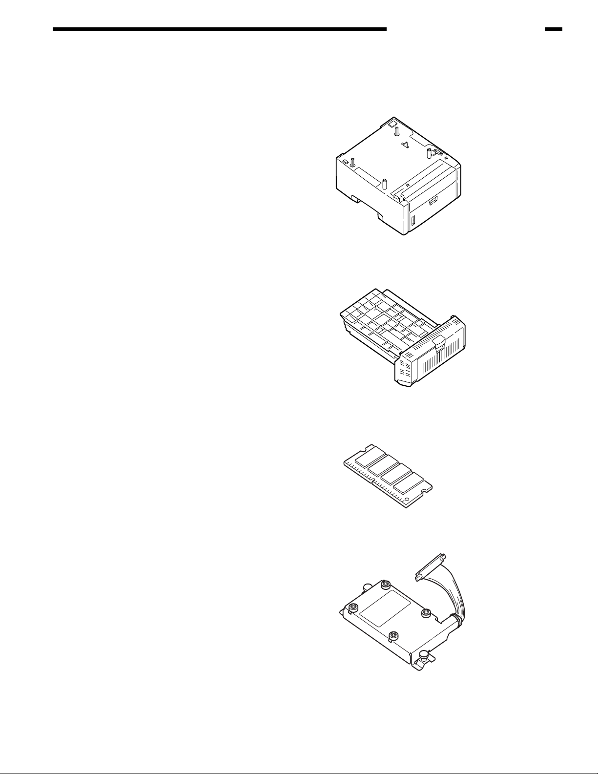
III. COMPOSITION OF OPTIONAL ITEMS
The following optional items are available for the printer:
(1) Second tray
AR-C265PFU
(530 sheet paper tray)
(2) Duplex Unit
AR-C265PADU
CHAPTER 1 CONFIGURATION
(3) Expansion Memory
AR-C265SM1 (256 MB)
AR-C265SM2 (512 MB)
For long printing, it is recommended to
add an expansion memory.
Hard disk
(4)
AR-C265HD (40 GB hard drive)
1-3
Page 10

CHAPTER 1 CONFIGURATION
IV. SPECIFICATIONS
Division
External
dimensions
Print width
Engine speed
(A4)
First print
time(A4)
Resolution
CPU
RAM
ROM
Power
consumption
Operating
environment
(Temperature)
Operating
environment
(Humidity)
Item
Width
Depth With duplex
Without duplex
Height
Mass With duplex
Without duplex
Print width
Monochrome
Color
OHP Color
OHP color/ monochrome
Monochrome
Color
Warm-up time
Low-noise mode
LED head
Max. input resolution
Output resolution
Gradation
Econo-mode
Core
I-cache
D-cache
Clock
Bus width
Resident
Option
Program + font
Power input
Power-save mode
Idle
Normal operation
Peak
When operating
When not operating
When stored
(For max. 1 yr.)
When transported
(For max. 1 mo.)
When transported
(For max. 1 mo.)
When operating
When not operating
When stored
When transported
AR-C265P
32/26ppm
435mm
621mm
563.5,mm
340mm
Approx.29kg
Approx.26kg
A4
32ppm
26ppm
9ppm*1
10ppm
8sec
9sec
45sec
Not applicable
600dpi
600x1200dpi
True 600x1200dpi
True 600x600dpi
600x600x4 level
Toner-saving by reducing lightness
PowerPC750CXR
32KB,
32KB (Internal L2 : 256KB)
500MHz
64bit
256 MB
256/512MB DIMM
Total capacit: 64MB
(120V)110~127VAC , (230V)220~240VAC
15W or less
100W (Average)
490W
1200W
10°C~32°C, 17°C~27°C(Full-color print quality guarantee temperature)
0°C~43°C, Power off
-10°C~43°C, With drum and toner
-29°C~50°C, With drum, but no toner
-29°C~50°C, With drum and toner
20%~80%, 50%~70%(Full-color print quality guarantee humidity)
Max. wet-bulb temp. : 25°C
10%~90%, Max. wet-bulb temp. : 26.8°C, with power off
10%~90%, Max. wet-bulb temp. : 35°C
10%~90%, Max. wet-bulb temp. : 40°C
1-4
Page 11

CHAPTER 1 CONFIGURATION
Division
Service life
Operation noise
Paper handling
Paper size
Min. paper size
Item
Printer life
Print duty
(M=L/12, A=L/12/5)
MTBF
(2.3% duty)
MPBF
MTTR
Starter toner
Toner life
(5% duty)
(Attached)
Standard
With 1st
new drum
Image drum life
Transfer belt life
Fuser unit life
In operation
(ISO7779Front)
In one-side print
On standby (ISO7779Front)
Power-save mode
Paper capacity(1st tray)
Paper capacity(2nd tray)
Paper capacity (Manual/auto)
Delivery
Duplex
Legal/universal or
A4-size cassette/universal
cassette
Automatic front feeder
or manual feeder
Two-sided
1st tray
2nd tray
Manual & auto (MPT)
Two-sided
AR-C265P
32/26ppm
420,000 pages, 5 years
Max. 50,000 pages / mo.
Average 4,000 pages / mo.
Not applicable
40,000 pages
20 minutes
Approx. 2,000
pages (Black)
Approx. 2,000
pages (Color)
Approx. 6,000
pages (Black)
Approx. 5,000
pages (Color)
Approx. 5,200
pages (Black)
Approx. 1,200
pages (Color)
Approx.
20,000 pages (With 3 pages / job)
Approx.27
,000 pages (When printed continuously) Drum counter automatically reset
60,000 pages (A4 size, with 3 pages / job), counter automatically reset
60,000 pages (A4 size), counter automatically reset
Legal/universal cassette: 300 sheets (70kg)
Legal/universal cassette (Optional): 530 sheets (70kg)
Standerd multi-purpose tray: 50 OHP sheets or 100 sheets of paper (70kg) or 10 envelopes
250 sheets (70kg) face-down/100 sheets (70kg)face-up in tray
1st cassette: Legal13/13.5/14, letter, executive, A4, A5, B5, A6
2nd
cassette: Legal13/13.5/14, letter, executive, A4, A5, B5
Reply-paid postcard (Max. 176gsm) (Multi-purpose tray)
Legal13/13.5/14, letter, executive
1200mm (When paper length exceeds 356, its width shall be from 210 to 215.9.)
Legal13/13.5/14, letter, executive
, A4, A5, B5, A6, C5, DL, Com-9,Com-10, Monarch, custom size, banners up to
Postcard, reply-paid postcard, Japanese-style envelope
, A4, A5 Custom size (Within permissible size and weight)
105x148mm:A6/(Models for Japan [100x148: Postcard size])
100x148: Postcard size
Approx.
55.6dBA
37dBA
Background level
Standard
148x210mm:A5
148x210mm:A5
12,000 pages (With 1 page / job)
1-5
Page 12

CHAPTER 1 CONFIGURATION
Division
Paper thickness
Operator panel
Status
switch/sensor
Communication
interface
Item
1st tray
2nd tray
Manual & auto (MPT)
Two-sided
LCD
LED (Color)
Switch
Paper out
Paper low
Toner low
Cover open
Fuser unit temp.
Paper size
Stacker full
Standard ( On PCB)
Option for OEM user
AR-C265P
32/26ppm
64~120gsm
64~176gsm
64-203gsm OHP sheets available
64~105gsm
16 characters in 2 line (Roman alphabet/Japanese kana)
No paper size indicated
Two
(Green x1, dark amber x1)
Six
Provided
Not provided
Provided (Y,M,C,K)
Provided
Provided
Not provided
Not provided
• Hi-Speed USB
• Ethernet
• Bidirectional parallel I/F conforming to IEEE std
1284-1994 (OEM)
Emulation
Font
Input/output switch
Standard
Emulation switch
Bit-map type face
Scalable 1 type face
Scalable 2 type face
Scalable 3 type face
Rasterizer
Bar code
OCR
Japanse PCL font
Japanese PS font
Automatic
PCL (PCL5c, HP-GL)
/ PCL XL2.1
SIDM (IBM-PPR,
EPSON-FX)
PostScript3 (Clone)
Automatic
Agfa
1(Line printer)
Agfa micro-type 86
Not available
Agfa micro-type 136
Agfa UFST 4.0 (PCL)
USPS
OCR-A,B
Not available
Not available
1-6
Page 13

CHAPTER 1 CONFIGURATION
Division
Optional Item
(Detachable)
Factory settings
Others
Note!
Item
RAM set
Tray mechanism
Cassette
Duplex print unit
Other
Japan
USB-IF logo
Windows logo
Operation with UPS
Operation with UPS (Uninterruptible power supply) is not guaranteed.
Expansion memories for AR-C265P
AR-C265P
32/26ppm
256,512 MB
2nd tray mechanism
Legal/universal (530 sheets)
Option
2.5" IDE HDD
User- installable (40 GB hard drive)
PCL+PS model
Available
Available
Do not use UPS
! Note
1-7
Page 14

CHAPTER 1 CONFIGURATION
V. INTERFACE SPECIFICATIONS
A. Parallel interface specifications (N/A)
B. USB interface specifications
Outline of USB interface
(1) Basic specifications
USB (Hi-Speed USB supported)
(2) Transmission mode
Full speed (Max. 12Mbps ± 0.25%)
High speed (Max.480Mbps ± 0.05%)
(3) Power control
Self power device
USB interface connectors and cables
(1) Connector
• Printer side: B-receptacle (Female)
Upstream port
Product equivalent to UBR24-4K5C00 (Made by ACON)
Connector pin assignment
• Cable side: B-plug (Male)
(2) Cables
Cable length: Specification: USB2.0 type cables five meters long or shorter. Cables two meters long
or shorter are recommended. (Shielded cable lines shall be used.)
USB interface signals
1
2
3
4
Shell
2
1
34
Signal name
Vbus
D-
D+
GND
Shield
Function
Power supply (+5V)
For data transfer
For data transfer
Signal ground
1-8
Page 15
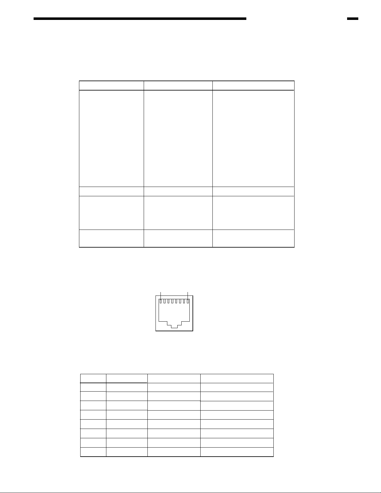
C. Network interface specifications
Outline of network interface
Basic specifications of network interface
CHAPTER 1 CONFIGURATION
Protocol family
TCP/IP
NetBEUI
NetWare
Ether Talk
Network protocol Application
IPv4, IPv6, TCP, UDP,
ICMP, ICMPv6, ARP
NetBIOS
SPX, IPX, SAP, RIP
ELAP, AARP, DDP, AEP,
ZIP, RTMP, ATP, NBP
Network interface connectors and cables
(1) Connectors
100 BASE-TX / 10 BASE-T (Automatically switched, not usable simultaneously)
18
LPR, RAW, IPP, FTP
SMTP/POP3
HTTP
HTTPS
Telenet
SNMPv1/v3
DHCP/BOOTP
DNS
UPnP
Rendezvous
SNTP
WINS, SMB
Q-Server over IPX
Q-Server over IP
R-Printer
N-Printer
PAP
2) Cables
RJ-45 connectorized non-shielded twisted-pair cable (Category 5 recommended)
Network interface signals
Pin No.
1
2
3
4
5
6
7
8
Signal name
TXD+
TXD-
RXD+
-
-
RXD-
-
-
Connector pin assignment
Direction
FROM PRINTER
FROM PRINTER
TO PRINTER
-
-
TO PRINTER
-
-
Function
Transmitting data +
Transmitting data -
Receiving data +
Not in use
Not in use
Receiving data -
Not in use
Not in use
1-9
Page 16

CHAPTER 2
EXPLANATION OF OPERATION
I. ELECTROPHOTOGRAPHIC
PROCESSING MECHANISM............ 2-1
II. PRINTING PROCESS....................... 2-6
Page 17
CHAPTER 2 EXPLANATION OF OPERATION
I. ELECTROPHOTOGRAPHIC PROCESSING MECHANISM
(1) Electrophotographic process
The electrophotographic process is explained briefly below:
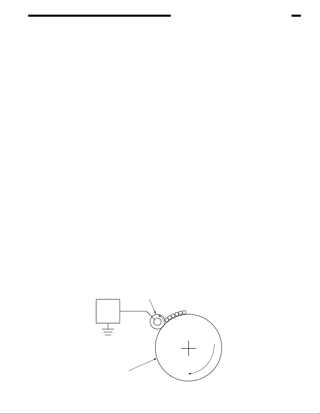
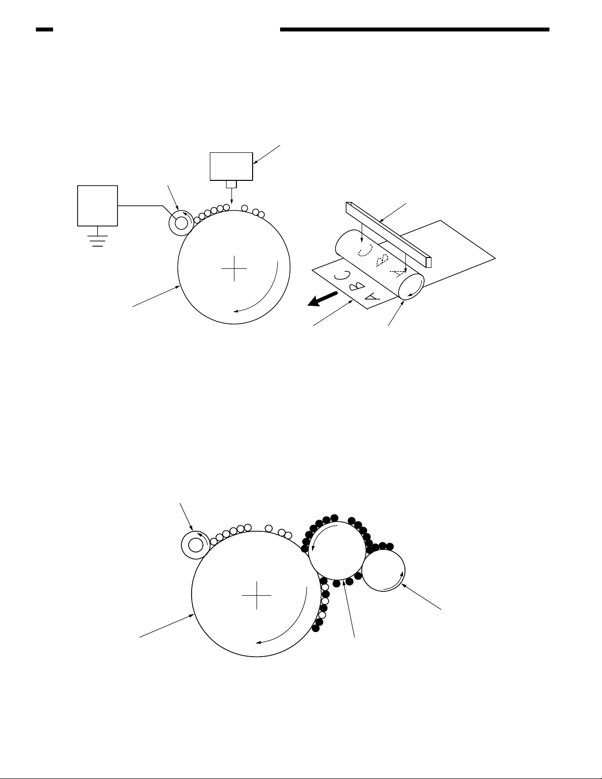
1. Charging
A voltage is applied to the CH roller to electrically charge the surface of the OPC drum.
2. Exposure
The LED head radiates light onto the charged OPC drum in accordance with the image
signal. The electric charge of the radiated part of the OPC drum surface attenuates
depending on the intensity of the light, thus forming an electrostatic latent image on the
OPC drum surface.
3. Development
Charged toner adheres to the electrostatic latent image of the OPC drum by electrostatic
power, and forms a visible image on the OPC drum surface.
4. Transfer
Paper is placed over the OPC drum surface and an electric charge is applied to it from
the back side by the transfer roller, so that the toner image is transferred to the paper.
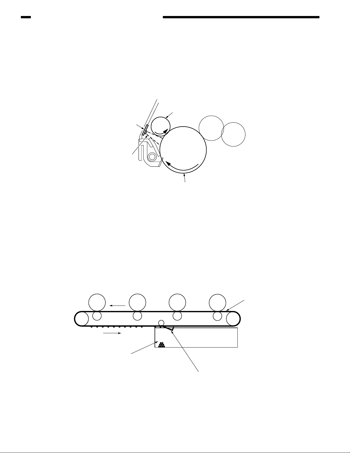
5. Drum cleaning
The drum cleaning blade removes toner remaining on the OPC drum after the transfer.
6. Removal of Electricity
7. Belt cleaning
The belt cleaning blade removes toner remaining on the belt.
8. Fuser
Heat and pressure are applied to the toner image on the paper to promote its fusion.
1. Charging
A voltage is applied to the charging roller, which is placed in contact with the OPC drum
surface, to charge the OPC drum surface.
Charging roller
Power
Supply
Unit
-
-
-
-
-
-
OPC drum
2-1
Page 18
CHAPTER 2 EXPLANATION OF OPERATION
2. Exposure
The light emitted from the LED head is radiated onto the charged surface of the OPC drum.
The charge of the radiated part of the OPC drum attenuates according to the intensity of the
light, forming an electrostatic latent image on the OPC drum surface.
Charging roller
LED head
Power
Supply
Unit
OPC drum
-
-
-
-
-
-
-
-
-
Paper
LED head
OPC drum
3. Development
Toner adheres to the electrostatic latent image on the drum surface, thereby turning the
electrostatic latent image into a toner image.
1. The sponge roller allows the toner to stick to the development roller.
2-2
Charging roller
-
-
-
-
-
-
-
-
-
-
-
Sponge roller
OPC drum
-
Development roller
2. The electrostatic latent image on the OPC drum surface is turned into a visible image
by the toner.
Page 19

CHAPTER 2 EXPLANATION OF OPERATION
4. Transfer
A sheet of paper is placed over the OPC drum surface, and an electric charge is given to the
paper from its back side by the transfer roller.
When a high voltage is applied to the transfer roller from the power source, the charge induced
on the transfer roller moves on to the surface of the paper through the contact part between
the transfer roller and the paper, the toner being attracted to the paper surface from the OPC
drum surface.
-
-
-
OPC drum
-
-
-
-
-
-
-
-
-
-
Paper
-
-+-
-+-
-+-
Transfer roller
+
+
+
-+-+-+-+-+-
+
-
+
-
+
-
+
-
+
-
+
Power
Supply
Transport belt
Unit
5. Drum cleaning
Unfixed toner remaining on the OPC drum is removed by the drum cleaning blade and
collected into the waste toner area of the toner cartridge.
Waste toner
Toner cartridge
Drum cleaning blade
ID unit
-
-
-
-
-
-
-
-
-
-
-
+
+
+
+
+
-
-
+
+
+
+
+
-
+
-
+
2-3
Page 20
CHAPTER 2 EXPLANATION OF OPERATION
6. Removal of Electricity
Electrically charge on the OPC drum surface decveases by exppsing the OPC drum surface
after transfer to the light.
Board for the light
of the removal of electricity
Light for the
removal of electricity
Charging roller
OPC drum
7. Belt Cleaning
Toner remaining on the transfer belt is scraped off by the belt cleaning blade and collected
into the waste toner box of the transfer belt unit.
Transport belt
2-4
Belt waste toner box
Belt cleaning blade
Page 21
CHAPTER 2 EXPLANATION OF OPERATION
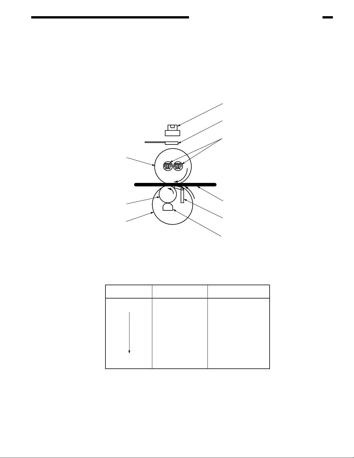
8. Fuser
The toner image which was transferred to the paper is applied heat and pressure as it passes
between the heat roller and the backup roller, and it is therefore fused onto the paper.
For the sake of safety, a thermostat is provided; it comes on to cut off the voltage supplied
to the heater if the heat roller temperature rises above a certain preset temperature.
Thermostat
Thermistor
Halogen Lamp
Heat Roller
Backup Roller
Beit
Fusing Temperature Settings
Paper thickness
Thin
Thick
Paper Type Settings
Light
Medium
Heavy
U.Heavy
OHP
Paper
Pad
Thermistor
Temperature Settings
Medium temp
High temp
Medium temp
Low temp
Low temp
2-5
Page 22
CHAPTER 2 EXPLANATION OF OPERATION
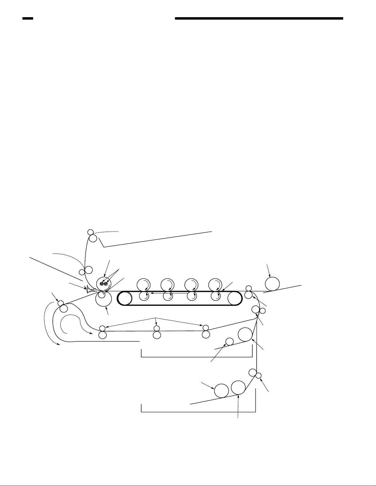
II. PRINTING PROCESS
The paper fed from Tray 1 or Tray 2 is carried by the paper feed roller, register roller L and transport
roller. When the paper is fed from the MPT, it is carried by the MPT paper feed roller and register
roller U. Then, an unfixed toner image is created on the paper transported onto the belt sequentially
through the electrophotographic process of KYMC. Thereafter, the image is fixed under heat and
pressure as the paper goes through the fuser unit. After the image has been fixed, the paper is
unloaded to the stacker either face-up or face-down stacker, according to the outputting method
selected by opening or closing the face-up stacker.
While the above refers to the one-sided print operation of the printer, its operation in two-sided print
will be explained below.
When two-sided print is conducted, the paper that has passed through the fuser unit following first
one-sided print is directed into the Duplex unit by the separator DUP. After entering the paper
reversal transport path, the paper is carried from there to the inside of the Duplex unit by the
inverting operation of the reversal roller. Then, after passed through the Duplex unit by the
transport roller that is located on the transport path inside the Duplex unit, the paper is fed along
the paper feed route of the Duplex unit to eventually merge the same route that comes from the
tray. From here on, the same operation as that of one-sided print of paper fed from the tray takes
place.
Face-up stacker
Separator DUP
Reversal roller
Face-down stacker
Heat roller
Halogen lamp
Backup roller
Belt
Paper reversal transport path
Transport roller
Subroller
Transport belt
Subroller
MPT paper feed roller
MPT
MPT
Register roller
Register roller
Paper feed roller
Transport roller
L
U
2-6
Paper feed roller
Page 23
CHAPTER 2 EXPLANATION OF OPERATION
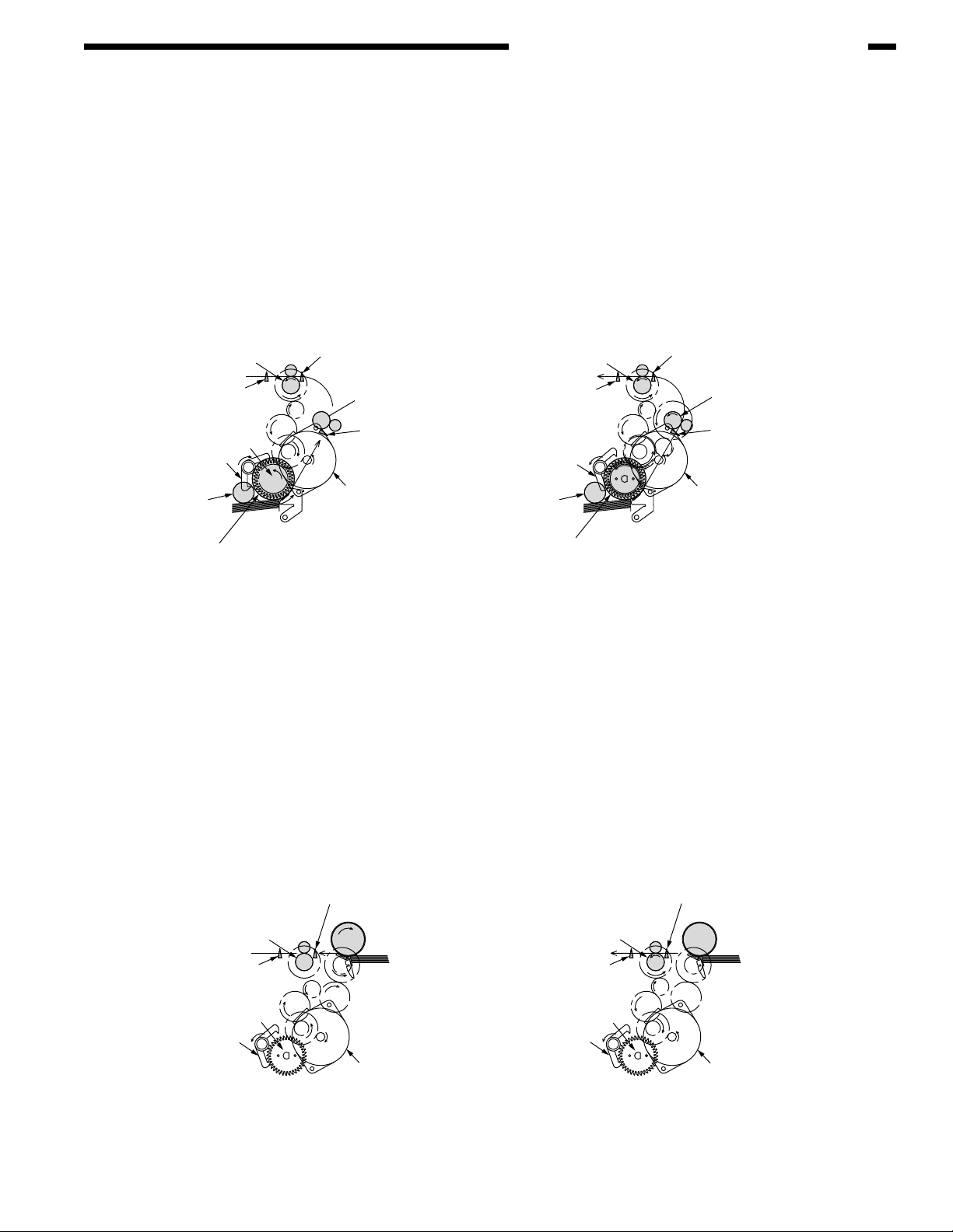
(1) Paper fed from 1st Tray
1. As illustrated in Figure 2-1, when the solenoid is ON, the register motor rotates
(Counterclockwise turn), transporting the paper until the IN1 sensor comes ON. (When the
solenoid is ON, the paper feed roller is driven.)
2. After causing the IN1 sensor to come ON, the paper is further carried over a certain distance
to finally hit register roller L. (This corrects skew of the paper.)
3. As shown in Figure 2-2, the solenoid is turned OFF and the paper is transported by register
roller L. (When the solenoid is OFF, register roller L is driven.)
Register Roller U
(Drive)
WR Sensor
Hopping Gear Assy
Solenoid Lever
(Solenoid ON)
Sub Roller
(Drive)
Hopping Roller
(Drive)
(2) Paper fed from MPT
1. As illustrated in Figure 2-3, when the solenoid is OFF, the register motor rotates (Clockwise
turn), transporting the paper until the IN2 sensor comes ON. (As the register motor rotates
clockwise, the MPT paper feed roller is driven.)
2. After causing the IN2 sensor to come ON, the paper is further carried over a certain distance
to finally hit register roller U. (This corrects skew of the paper.)
IN2 Sensor
Registration Roller L
(Stop)
IN1 Sensor
Solenoid Lever
(Solenoid OFF)
Registration Motor
(CCW)
Paper
Register Roller U
WR Sensor
Sub Roller
(Stop)
(Drive)
Paper
Hopping Roller
(Stop)
Figure 2-1 Figure 2-2
IN2 Sensor
Registration Roller L
(Drive)
IN1 Sensor
Registration Motor
(CCW)
3. As shown in Figure 2-4, the register motor rotates (Counterclockwise turn) to let register
roller U transport the paper. (As the register motor rotates counterclockwise, register roller
U is driven.)
IN2 Sensor
Registration Roller U
(Stop)
WR Sensor WR Sensor
Hopping Gear Assy
Solenoid Lever
(Solenoid OFF)
MPT Hopping Roller
Paper Paper
Hopping Gear Assy
Solenoid Lever
(Solenoid OFF)
Registration Motor
(CW)
Figure 2-3 Figure 2-4
IN2 Sensor
Registration Roller U
(Drive)
Registration Motor
(CCW)
2-7
Page 24
CHAPTER 2 EXPLANATION OF OPERATION
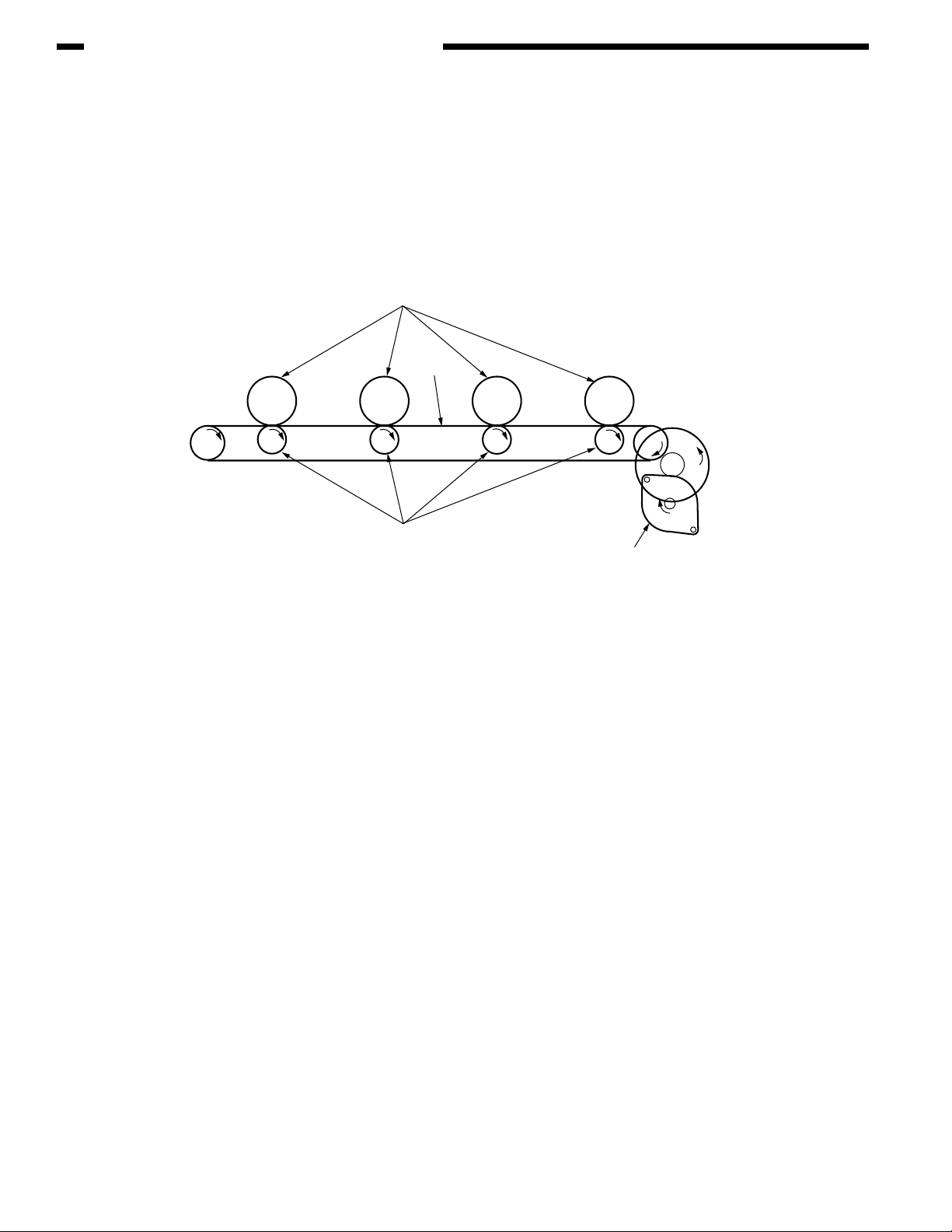
(3) Transport belt
1. As the transport belt motor rotates in the direction of the arrow, the transport belt is driven.
The belt unit consists of one transport roller placed immediately underneath each color
drum, with a transport belt inserted in between them.
As the specified voltage is applied, the transport belt and the transport rollers send the paper
located on the transport belt to the fuser unit while transferring to it the toner image present
on each color drum.
Drum
Carrier belt
K
KYMC
Carrier (transfer) roller
Figure 2-5
Carrier (transfer) belt motor
2-8
Page 25
CHAPTER 2 EXPLANATION OF OPERATION
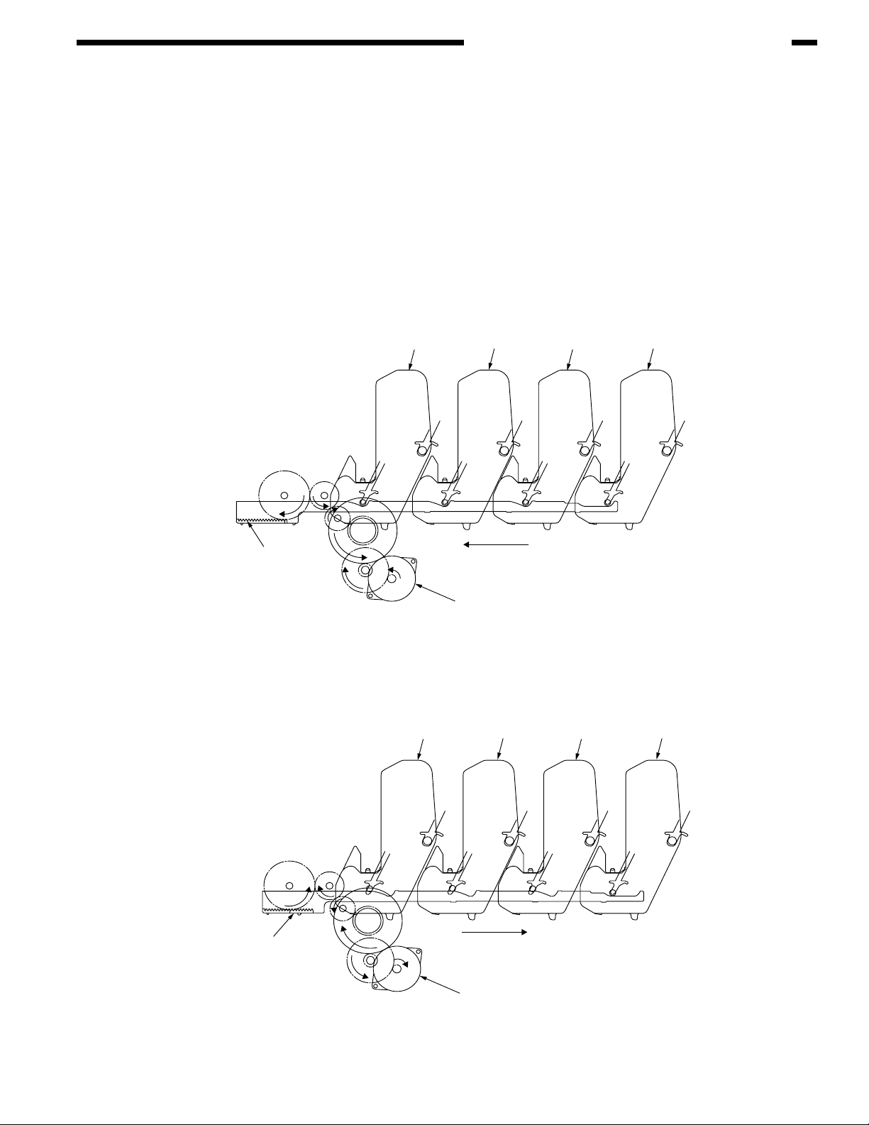
(4) Up/down-motions of ID units
1. The up/down-motions of the ID units take place driven by the lift-up motor.
2. Figure 2-6 shows the motions of the different ID units when the printer is operated for color
print. As the lift-up motor rotates (Clockwise turn), the lift-up link slides to the left, causing
the ID units to come down, as can be seen in Figure 2-6. Namely, the printer is readied for
color print.
3. Figure 2-7 shows the motions of the different ID units when the printer is operated for
monochrome print. As the lift-up motor rotates (Counterclockwise turn), the lift-up link slides
to the right, causing the ID units to go up, except for the K-ID unit, as can be seen in Figure
2-7. Namely, the printer is readied for monochrome print.
ID Unit Operations During Color Printing
C-ID Unit down
C-ID Unit
M-ID Unit down
Y-ID Unit down
K-ID Unit down
M-ID Unit Y-ID Unit K-ID Unit
Lift uplink
Figure 2-6
ID Unit Operations During Monochrome Printing
C-ID Unit
C-ID Unit lift up
M-ID Unit lift up
Y-ID Unit lift up
K-ID Unit down
Lift uplink
C-ID Motor
(CCW)
M-ID Unit Y-ID Unit
K-ID Unit
Figure 2-7
C-ID Motor
(CW)
2-9
Page 26
CHAPTER 2 EXPLANATION OF OPERATION
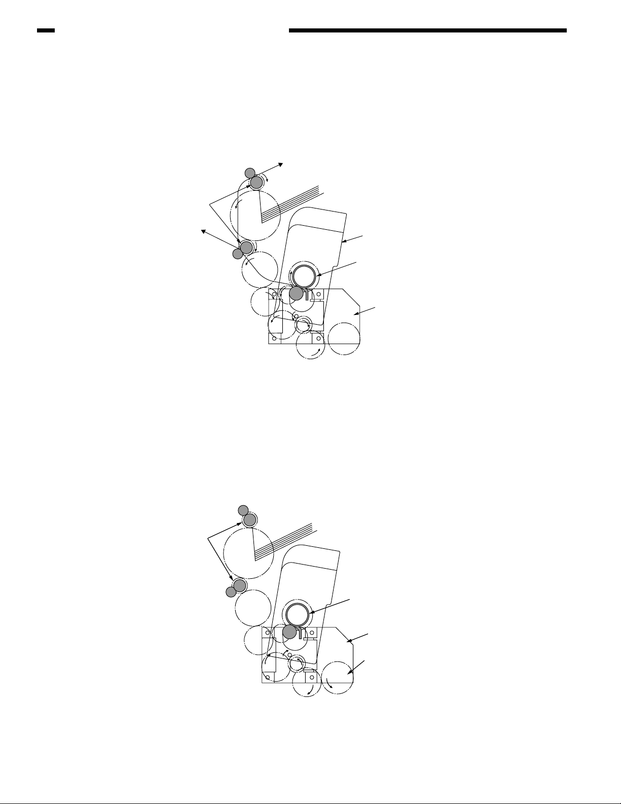
(5) Fuser unit and paper output
1. As illustrated in Figure 2-8, the fuser unit and delivery roller are driven by the DC motor. As
the fuser motor rotates (Counterclockwise turn), the heat roller is turned. This roller fixes
a toner image by heat and pressure.
2. At the same time, the delivery roller rotates to output the paper.
Eject Roller
(Drive)
Fuser Unit
Heat Roller
(Drive)
Fuser Motor
(CCW)
Figure 2-8
(6) Cover-opening motion of color drift sensor and density sensor
1. As illustrated in Figure 2-9, when the fuser motor rotates (Clockwise turn), the coveropening gear rotates, causing the color drift sensor and density sensor cover to open.
2. As the fuser motor rotates in reverse (Counterclockwise turn), the engagement of the coveropening gear is freed, and the color drift sensor and density sensor cover now closes.
Eject Roller
(Stop)
Heat Roller
(Stop)
Fuser Motor
(CW)
Cover Open Gear
2-10
Figure 2-9
Page 27
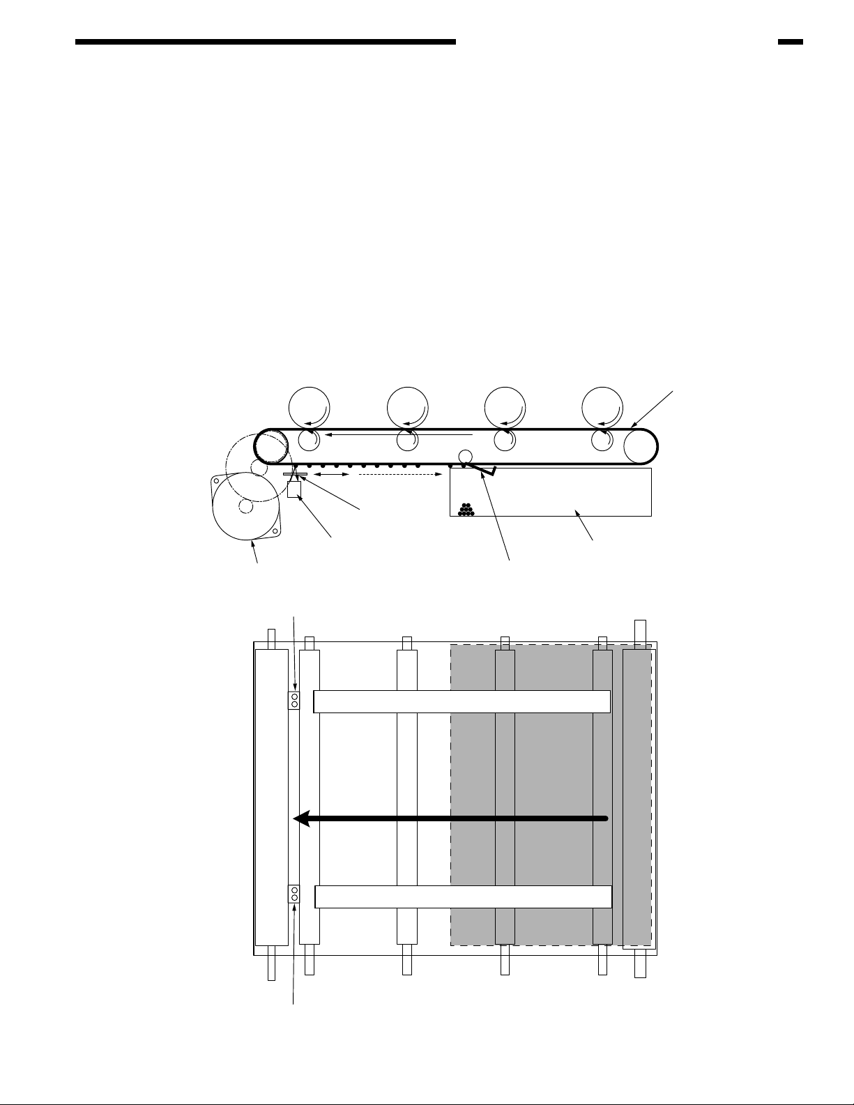
Outline of color drift correction
The color drift correction is implemented reading the correction pattern that is printed on the belt
with the sensor located inside the sensor shutter under the belt unit. This sensor is used to detect
and correct the pattern.
Automatic start timing of color drift correction:
• At power-on
• When the cover is closed after it is opened briefly
• When 400 pages or more have been printed since previous execution
A correction error may be issued due to an inadequate toner amount of the pattern generated,
a sensor stained with toner, deficient opening/closing of the shutter, or for other reasons.
However, even if an error is issued, it is not indicated on the operator panel. Therefore,
forcible color drift correction will have to be performed in the self-diagnostic mode (page 4-21)
to check the error indication.
CHAPTER 2 EXPLANATION OF OPERATION
Transport belt
Belt motor
Color drift sensor
Sensor shutter
Color drift sensor
Right color drift correction pattern
Left color drift correction pattern
Belt waste toner box
Belt cleaning blade
Color drift sensor
2-11
Page 28

CHAPTER 2 EXPLANATION OF OPERATION
Error checking methods and remedial methods
The color drift correction test function among the other self-diagnostic functions is employed to
check errors. (page 4-21)
Remedial methods against different errors
• CALIBRATION (L or R), DYNAMICRANGE (L or R)
Check 1: If the above indication appears, check the connected state of the sensor cable
(FFC).
If the connected state is found abnormal, restore it to the normal state.
Check 2: Check to see whether the sensor surface is stained with toner, paper dust or any
other foreign matter.
If it is found stained, wipe it clean.
Check 3: Check to see whether the sensor shutter opens and closes normally, by the
MOTOR & CLUTCH TEST of the self-diagnostic function. If the shutter operates
imperfectly, replace the shutter unit.
• BELT REFLX ERR
Check 4: If this indication appears, check the cleaned state of the toner remaining on the
belt surface, in addition to making the above checks 1, 2 and 3. Take out the belt
unit, turn the drive gear located on the left rear side, and ensure that the belt
surface has been cleaned thoroughly.
If cleaning is not achieved perfectly and there still remains toner on the belt
surface after the drive gear has been turned, replace the belt unit.
• (Y or M or C) LEFT, (Y or M or C) RIGHT, (Y or M or C) HORIZONTAL
Check 5: If the above indication appears, check to see whether the toner is running short,
based on an NG-issuing color.
Replace the toner cartridge, as needed.
2-12
Page 29
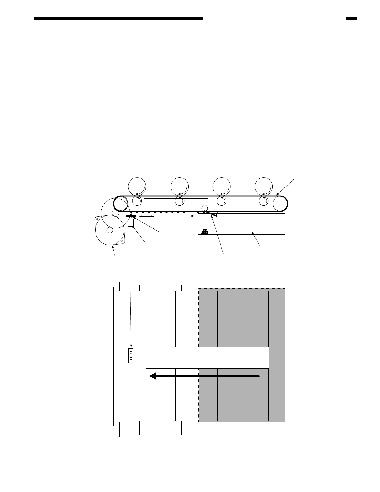
Outline of density correction method
The density correction is implemented reading the correction pattern that is printed on the belt with
the sensor located inside the sensor shutter under the belt unit.
Automatic start timing of density correction:
• If the environment at power-on is greatly different from the one in which previous print was
executed.
• If at least one or more of the four ID count values are close to those of a new product at
power-on.
• When the ID count value exceeds 500 counts since previous execution.
A correction error may be issued due to an inadequate toner amount of the pattern generated, a
sensor stained with toner, deficient opening/closing of the shutter, or for other reasons. However,
even if an error is issued, it is not indicated on the operator panel. Therefore, forcible density
correction will have to be performed in the self-diagnostic mode (page 4-22) to check the error
indication.
CHAPTER 2 EXPLANATION OF OPERATION
Transport belt
Belt motor
Density sensor
Sensor shutter
Density sensor
Density correction pattern
Belt waste toner box
Belt cleaning blade
2-13
Page 30

CHAPTER 2 EXPLANATION OF OPERATION
Error checking methods and remedial methods
The density correction test function among the other self-diagnostic functions is employed to check
errors. (page 4-22)
Remedial methods against different errors
• CALIBRATION ERR, DENS SENSOR ERR
Check 1: If the above indication appears, check the connected state of the sensor cable.
If the connected state is found abnormal, restore it to the normal state.
Check 2: Check to see whether the sensor surface is stained with toner, paper dust or any
other foreign matter.
If it is found stained, wipe it clean.
• DENS SHUTTER ERR
Check 3: Check to see whether the sensor shutter opens and closes normally, by the
MOTOR & CLUTCH TEST of the self-diagnostic function. If the shutter operates
imperfectly, replace the shutter unit.
• DENS ID ERR
Check 4: Take out the ID unit and examine it to see if the drum surface has any abnormal
toner smudge.
Replace the LED head (Blurred focus), or replace the ID unit.
To test-operate a new ID unit, use the Fuse Keep Mode of the maintenance
menu.
2-14
Page 31

Principle of toner sensor detection
Toner LOW is detected by the toner sensor (Reflection sensor) installed inside the printer. The
shielding plate is mounted inside the ID and rotates in synchronization with toner agitation.
Moreover, the ID has a shutter fitted. The shutter is synchronized with the operation lever of the
toner cartridge, and the toner sensor can detect that the toner cartridge has been loaded properly.
Detection may not take place normally, and a toner sensor error may be issued, if the shield plate
or toner sensor is stained with toner, or if the ID unit and toner sensor do not remain exactly opposite
to each other in their positions.
CHAPTER 2 EXPLANATION OF OPERATION
Shutter
Toner Sensor
Principle of toner counter
After image data is developed to binary data which the printer can print, it is counted by an LSI as
a number of print dots. The amount of toner consumed is calculated from that count value, and the
remaining amount of toner is thus indicated. As opposed to this, the toner LOW detection by the
toner sensor is implemented when the toner amount remaining inside the ID unit physically
decreases to below a certain level.
Principles of ID, belt and Fuser counters
ID counter: One count represents the value that results from dividing the amount of rotation
of the drum by three when three A4-size sheets are printed continuously.
Belt counter: One count represents the value that results from dividing the amount of rotation
of the belt by three when three A4-size sheets are printed continuously.
Fuser counter: One count is registered when paper is shorter than the length of Legal 13-inch
paper. When paper is longer than that, the count number is determined by the
number of times the Legal 13-inch paper length is exceeded. (Decimal fractions
rounded up)
Shield
plate
2-15
Page 32

CHAPTER 3
INSTALLATION
I. CAUTIONS, AND DO’S AND
DON’TS ............................................. 3-1
II. UNPACKING METHOD..................... 3-2
III. PRINTER INSTALLATION
INSTRUCTIONS................................ 3-3
IV. LISTING OF COMPONENT UNITS
AND ACCESSORIES ........................ 3-4
V. ASSEMBLING METHOD................... 3-5
A. Assembly of printer main body ..... 3-5
B. Connection of power cable......... 3-11
C. Installation of optional items....... 3-14
D. Confirmation of recognition
of optional items ......................... 3-22
VI. MENU MAP PRINT .........................3-23
VII. CONNECTION METHODS .............3-24
VIII. CONFIRMATION OF PAPER
USED BY THE USER...................... 3-25
Page 33

I. CAUTIONS, AND DO’S AND DON’TS
• Do not install the printer at high temperature or near fire.
• Do not install the printer in a location where chemical reaction can take place (laboratory, etc.).
• Do not install the printer in the proximities of inflammable solvents, such as alcohol, paint thinner,
etc.
• Do not install the printer within reach of small children.
• Do not install the printer in an unstable location (e.g., on a rickety bench or grade).
• Do not install the printer in a location laden with moisture or heavy dust, or in direct sun.
• Do not install the printer in an environment with sea wind or corrosive gas.
• Do not install the printer in a location with heavy vibration.
• In the event that the printer is inadvertently dropped or its cover is damaged, remove the power
plug from the power outlet and contact Customer Center.
Such mishap could lead to an electric shock, fire or injury.
• Do not connect the power cord, printer cable or grounding wire in any other manner than the way
specified in the manual. Failure to observe the above could result in fire.
• Do not stick in an object into the vent hole.
Such action could lead to an electric shock, fire or injury.
• Do not place a glass filled with water or the like on the printer.
Such action could lead to an electric shock or fire.
• When the printer cover has been opened, do not touch the fuser unit.
Burns could be suffered.
• Do not throw the toner cartridge or the image drum cartridge into fire.
Dust explosion could cause burns.
• Do not use a highly combustible spray near the printer.
Fire could be caused, since the printer contains a part that gets extremely hot inside.
• In the event that the cover becomes unusually hot, emits smoke, ill odor, or abnormal noise,
remove the power plug from the power outlet and contact Customer Center.
Fire could break out.
• If water or any other liquid enters the inside of the printer, remove the power plug from the power
outlet and contact Customer Center.
Fire could break out.
• If a pao not operate or disassemble the printer in any other manner than the way specified in the
manual.
Failure to observe this warning could result in an electric shock, fire or injury.
CHAPTER 3 INSTALLATION
3-1
Page 34

CHAPTER 3 INSTALLATION
• Do not install the printer in a location where its vent hole is blocked.
• Do not install the printer directly on a shaggy carpet or rug.
• Do not install the printer in a sealed room or other location with poor ventilation or permeability.
• Install the printer away from a heavy magnetic field or noise source.
• Install the printer away from a video monitor or TV.
• To move the printer, hold it by both sides of it.
• This printer, which weighs Approx. 29kg (with Duplex)/Approx. 26kg (w/o Duplex), should be lifted
up by two or more persons.
• When the printer has the power switched on or is printing, do not come close to the paper delivery
section.Such action could lead to injury.
When the precautionary notes concerning the installation and operation are explained, the user
should be referred to the precautionary notes given in the User's Manual. Especially, give thorough
explanation on the power cord and grounding wire.
1+
II. UNPACKING METHOD
Personal injuries may occur.
Make sure to lift up this printer by two or more persons, since it weighs Approx. 29kg (with Duplex)/
Approx. 26kg (w/o Duplex)
• Remove the four handles from the sides of the box and lift up the corrugated fiberboard
box.
3-2
Page 35

CHAPTER 3 INSTALLATION
III. PRINTER INSTALLATION INSTRUCTIONS
• Install the printer in a location where the following temperature and humidity are met:
Ambient temperature: 10 - 32˚C
Ambient humidity: 20 - 80 %RH(Relative humidity)
Max. wet-bulb temperature: 25˚C
• Use caution to avoid dew condensation.
• If the printer is installed in a location with ambient relative humidity below 30%, use a
humidifier or antistatic mat.
Installation space
• Place the printer on a flat desk large enough to accommodate its footings.
• Provide ample spaces around the printer.
Plan view
60cm
Side View
20cm
20cm
100cm
60cm
20cm
100cm
20cm
70cm70cm
3-3
Page 36

CHAPTER 3 INSTALLATION
IV. LISTING OF COMPONENT UNITS AND ACCESSORIES
• Check to make sure that the component units are free from damage, dirt or other irregularities
in the appearance.
• Ensure that none of the accessories to the units is missing and that they are free from
breakage or other flaw.
• If any irregularity is discovered, contact User Management Section for instructions.
Personal injuries may occur.
Make sure to lift up this printer by two or more persons, since it
weighs Approx. 29kg (with Duplex)/Approx. 26kg (w/o Duplex)
Printer (Main body)
AR-C265P
Image drum cartridges (4 sets) fitted with starter toner cartridges (Installed in the printer)
Inform the user that the toner cartridges and image drum cartridges can be separated one from
the other.
Printer software CD-ROM
LED lens cleaner
Power cord
Warranty Card and User Registration Card
User's Manual (Setup)
User's Manual (CD-ROM)
Quick Guide
Dedicated bag for Quick Guide
3-4
Note!
No printer cable is supplied with the printer.
Page 37

V. ASSEMBLING METHOD
A. Assembly of printer main body
Removing the protective materials
1) Peel off the protective tapes (5) and the slip of paper from the front part of the printer,
and also peel off the protective tapes (2) from the back of the printer.
Slip of paper
CHAPTER 3 INSTALLATION
Protective Tape
2) Draw out the paper cassette.
3) Pull out the retainer forward.
4) Open the top cover by pressing the OPEN button.
Retainer
Paper cassette
OPEN button
5) Detach the stopper release (Orange) while pressing down the lever (Blue) of the fuser unit
in the direction of arrow 1.
Note!
Instruct the user of the printer to be sure to keep the stopper release, which is used for
transporting the printer, at hand.
Lever (Blue) of fuser unit
Protective Tape
1
212
Stopper release (Orange)
3-5
Page 38

CHAPTER 3 INSTALLATION
Installing the image drum cartridges
1) Take out the image drum cartridges (4) gently along with the toner cartridges attached.
Note!
• The image drum (Green tubular section) is extremely vulnerable. Exert good caution in
handling it.
• Do not expose the image drum cartridges to direct sun or intense light (1500 lux or
more). Do not expose them to the room lighting for over five minutes.
• In the above operation, be careful not to actuate the blue lever of the toner cartridge.
Toner cartridge
Image drum cartridge
2) Place the image drum cartridge on a flat-top desk or the like, peel off the tape fastening
protective sheet 1, and pull out the sheet in the direction of the arrow.
Note!
Do not work with the image drum floating in the air.
Protective sheet 1
Tape
Protective sheet 1
Protective sheet 2
3) Pull out protective sheet 2 from the image drum cartridge in the direction of the arrow.
3/ Protective sheet
Protective sheet 2
3-6
Page 39

CHAPTER 3 INSTALLATION
4) Match the label colors of the image drum cartridges to those on the printer.
5) Gently put the image drum cartridges (4) back in their respective positions.
Label
Image drum cartridge
Labels
6) Turn the blue levers (4) of the toner cartridges fully into the direction of the arrow.
Note!
• The starter toners (Toner cartridges supplied with the product) can print approximately
1500 A4-size sheets with 5% print density.
• If the error message [CHECK TONER CARTREGE] nstays permanently on the
operator panel,check to make sure that the levers of the toner cartridges have fully
been moved in the direction of the arrow.
• If normal starter toner cartridges have been used, the starter toners can no longer be
used. First use the starter toners, and use normal toners after the starter toners are
exhausted.
• Make sure to change the starter toners only after [REPLACE TONER] is indicated.
If the starter toners are replaced before the above message appears, the correct toner
remaining level will not be able to be indicated.
Blue
Lever
3-7
Page 40

CHAPTER 3 INSTALLATION
1) Pull out the paper cassette.
Note!
Do not peel off the rubber attached to the plate.
2) Set the paper stopper securely, according to the paper size.
Paper stopper
3) Loosen the paper well and line up its vertical and lateral edges.
Paper guide
Plate
4) Load the paper with the print face down.
Note!
• Place the paper aligned to the forward end of the paper cassette.
• Load the paper by avoiding to exceed the (
70kg ream weight paper).
5) Fasten the paper with the paper guides.
6) Put the paper cassette back into the printer.
mark
) mark of the paper guide. (300 sheets of
Print face down
3-8
Paper guide
Indication of remaining
amount of paper
Page 41

Loading paper in the multi-purpose tray
1) Open the multi-purpose tray and also the paper supporter.
2) Set the manual feed guide to the paper size.
3) Line up the vertical and lateral edges of the paper.
CHAPTER 3 INSTALLATION
Multi-purpose tray
Manual feed guide
Multi-purpose tray
Paper supporter
Manual feed guide
4) Insert the paper, print-face up, along the manual feed guide straight as far as it will go.
mark
5) Press the set button.
Set button
3-9
Page 42

CHAPTER 3 INSTALLATION
Storing the Quick Guide
Paste the dedicated Quick Guide bag to the printer, and put the Quick Guide in it.
Turning back the dedicated Quick Guide bag and peeling off the adhesive double coated tapes (2).
Adhesive double coated tapes
Pasting the dedicated bag to the printer.
Vent hole
Dedicated Quick Guide bag
Note!
When pasting the bag, avoid blocking the vent hole of the printer.
Quick Guide
3-10
Page 43

B. Connection of power cable
Power requirements
• Observe the following conditions:
AC: 115 V ± 10%
Power frequency: 60Hz ± 2Hz Approx.
• If the available power is unstable, have it inspected and corrected by a qualified electrician.
• The maximum power consumption of this printer is 1200W. Ensure that the power source offers
an ample margin in the power capacity.
It may expose you to electric shocks or cause a fire.
• Always before connecting or disconnecting the power cord and grounding wire, first turn off the
power switch.
• The grounding wire should be connected to a grounding terminal. Do Not in any event tie it to a
water service piping, gas piping, ground of telephone lines, lightning arrester or the like.
• When plugging in or unplugging the power cord, be sure to hold the power plug.
• Insert the power plug securely into the power outlet as far as it will go.
• Do not insert or remove the power plug with a wet hand.
• Lay the power cord in a location where it is not likely stepped on, and avoid placing anything on
the power cord.
• Do not bundle or tie the power cord.
• Do not use a damaged power cord.
• Avoid a starburst connection of cables.
• Do not connect the printer to the same power outlet shared by other electric appliances.
Especially, if the printer is connected to the same power outlet in conjunction with an airconditioner, copy machine or shredder, electric noise may cause false operation of the printer. If
it is inevitable to connect them to the same power outlet, use a commercial noise filter or noisecut transformer.
• Operate the printer with the supplied power cord only.
• Do not use an extension cord. If it is inevitable to use an extension cord, use one with rating of 15A
or more.
• Use of an extension cord may hinder the printer from operating normally because of voltage drop.
• Do not turn off the power or pull out the power plug while the printer is printing.
• If the printer is going to be placed out of use for an extended period of time due to a long spell of
CHAPTER 3 INSTALLATION
About the connections of the power cord and grounding wire, the user should be given thorough
explanation on the basis of the User's Manual.
3-11
Page 44

CHAPTER 3 INSTALLATION
During holidays or a trip out of town, unplug the power cord.
Connecting the power cord
Note!
Ensure that the power switch is in OFF (O).
1) Insert the power cord into the printer.
2) After connecting the grounding wire to the ground terminal of the power outlet, insert the
power plug into the power outlet.
OI
Ground terminal
Grounding wire
Pressing ON (|) of the power switch
The following indication will be produced on the operator panel, and [Online] will appear when the
printer has started up completely.
OI
RAM checking
* * * * * * * * * * * * * * * *
Initializing
3-12
PLEASE WAIT
[Online] and [Inspect] lights
and backlight flash.
Online
Tray 1
Page 45

Turning off the power
On the AR-C265P which is not equipped with the built-in type hard disk (optional) the power
can be turned off as is.
CHAPTER 3 INSTALLATION
OI
Note!
On the AR-C265P equipped with the built-in type hard disk (optional), do not outright
turn off the power, but follow the procedure described below.
Note!
Do not turn off the power while the printer is printing.
• Abrupt disconnection of the power could damage the built-in hard type disk, disabling
it.
• [SHUTDOWN MENU] is displayed only when the printer is equipped with the optional
built-in type hard disk.
(1) Press the "Back" switch for four seconds or longer to cause
[SHUTTING DOWN] to appear.
(2) Press the "Set" switch.
[SHUTDWN] is displayed, and the shutdown processing begins
(3) When [PLEASE POW OFF/SHUTDOWN COMP] shows up, press OFF (O) of the power
switch.
OI
3-13
Page 46

CHAPTER 3 INSTALLATION
C. Installation of optional items
(1) Installation of expansion memory set
AR-C265P expansion memory
Model name
Memory volume
(Total memory volume)
None (Standard)
AR-C265SM1
AR-C265SM2
Note!
• Be sure to use genuine Sharp parts. If any other parts are used, the printer will not
256MB (256MB)
+256MB (512MB)
+512MB (768MB)
function.
• Adding 64-MB memory is recommended for (600 x 600dpi x 2bit) banner-sheet printing.
Added 64-MB memory may reduce the time for (600 x 1200dpi or 600 x 600 x 2bit)
duplex printing.
• To conduct long print on the AR-C265P, it is recommended to add a 256MB
expansion memory.
• There is only one memory slot.
Turning OFF the printer power and disconnecting the power cord
Note!
If an expansion memory is installed with the power switched ON, the printer may be
broken.
OI
Opening the top cover and front cover
3-14
OPEN button
Handle
Top cover
Front cover
Front cover
Page 47

Remove Side Cover
1) Loosen the screw (1).
2) Remove the side cover.
To remove the side cover, slide it while holding up its upper part.
Front cover
Top cover
CHAPTER 3 INSTALLATION
Screw
1
Side cover
Installing the memory
1) Before taking the memory out of the bag, place the bag in contact with a metal part to
fuser eliminate its static electricity.
2) Insert the memory into the idle slot.
3) Ensure that it is securely fastened by the right and left lock levers.
Note!
• Do not touch the electronic parts and connector pins.
• Pay attention to the orientation of the memory. The terminal part of the memory has a
notch, which is designed to engage with the connector of the slot.
2
3-15
Page 48

CHAPTER 3 INSTALLATION
Attaching the side cover
1) Mount the side cover.
2) Fasten it with the screw (1).
3) Close the top cover and front cover.
Front cover
3
Top cover
3
2
Screw
Side cover
1
(2) Installation of second tray unit
This tray is intended to increase the amount of paper that can be loaded in the printer. It holds
530 sheets of 70kg ream weight paper, allowing to print 930 sheets continuously when
combined with the standard paper cassette and multi-purpose tray.
Type: AR-C265PFU
Turning OFF the printer power and disconnecting the power cord
3-16
Note!
If an expansion memory is installed with the power switched ON, the printer may be
broken.
OI
Page 49

Placing the printer on the second tray unit.
CHAPTER 3 INSTALLATION
Note!
The printer weighs Approx. 29kg (with Duplex)/Approx. 26kg (w/o Duplex). It should be
lifted up by two or more persons.
1) Align the holes in the bottom of the printer to the protrusions of the second tray unit.
2) Place the printer gently on the second tray unit.
To detach the second tray unit, follow the same procedure inversely.
Holes in the printer bottom
Protrusions
(3) Installation of duplex unit
This unit is used for printing on two sides of paper.
Note!
For two-sided printing, it is recommended to add an expansion memory. For details,
see "Expansion memories."
Type: AR-C265PADU
Turning OFF the printer power and disconnecting the power cord
Note!
If an expansion memory is installed with the power switched ON, the printer may be
broken.
OI
3-17
Page 50

CHAPTER 3 INSTALLATION
Peeling the protective tapes off the duplex unit
Install Duplex Unit
1) Insert the duplex unit into the lower part on the back of the printer as far as it will
2) Ensure that the claw on either side of the duplex unit is securely accommodated
in the hole of the printer.
Protective tapes (2)
go.
Holes
Claws
Two-sided print unit
(4) Installation of built-in type hard disk
This is a built-in type hard disk to be added to the printer. It is used to conduct confirmation print,
authentication print, to store print jobs, or to make buffer print, and also when the [ COLLATE
FAIL] is indicated in a section-by-section print. Fonts cannot be downloaded to it.
Note!
When the printer has a built-in type hard disk installed, make certain to switch off the
printer after executing the shutdown menu. If the power is turned off outright, the hard
disk may be damaged and broken.
Type: AR-C265HD
3-18
Memo
The hard disk is segmented into the three partitions of "PCL," "Common" and "PSE."
When the printer is shipped out of the factory or the hard disk is initialized, the following
sizes are assigned to the partitions:
Page 51

CHAPTER 3 INSTALLATION
Turning OFF the printer power and disconnecting the power cord and printer cable
Note!
If an expansion memory is installed with the power switched on, the printer may be
broken.
Opening the top cover and front cover
1) Open the top cover by pressing the OPEN button.
OI
Top cover
Front cover
OPEN button
Handle
2) Push up the handle located in the center of the front cover and pull the front cover forward.
Front cover
Note!
The way the front cover is opened is different from that of the multi-purpose tray. (See
figure below.)
Multi-purpose tray
3-19
Page 52

CHAPTER 3 INSTALLATION
Detaching the side cover
1) Loosen the screw (1).
2) Remove the side cover.
To remove the side cover, slide it while holding up its upper part.
Front cover
Top cover
2
1
Screw
Side cover
Memo
If you have difficult detaching the side cover, check to see if the front cover is open.
Installing the built-in type hard disk
1) Insert part "a" of the built-in type hard disk into hole "b" of the printer main body, and align
the positions of the screw holes.
2) Install the two screws.
3) Push in the connector, until it snags in there with a click.
Front cover
b
Multi-purpose tray
3-20
a
Connector
Hard disk
Page 53

Attaching the side cover
1) Mount the side cover.
2) Fasten it with the screw (1).
3) Close the top cover and front cover.
Front cover
3
Top cover
3
1
CHAPTER 3 INSTALLATION
Screw
2
Side cover
Connecting the power cord and printer cable to the printer, and turning on the
power
Executing the Menu Map print, and ensuring that the built-in type hard disk has
been installed properly.
1) Execute the Menu Map print.
Conduct the Menu Map print by referring to "VI. Menu Map print."
2) Ensure that the capacity of the built-in type hard disk is indicated in "HDD."
Memo
Note!
The capacity of the hard disk may be different from the example shown above.
If no HDD capacity is indicated, redo the installation of the built-in type hard disk.
Then, setting needs to be made with the printer driver to have the built-in type hard disk
recognized.
If there is no printer driver set up, see Sections 3 to 9 of the Setup Part of the User's Manual,
and set up the printer driver. Then, make the setting.
3-21
Page 54

CHAPTER 3 INSTALLATION
D. Confirmation of recognition of optional items
To check to see whether or not the optional items have been installed properly, execute the Menu
Map print by referring to "VI. Menu Map print".
(1) Confirmation of recognition of expansion memory
Checking the contents of the Menu Map.
Check the total memory volume indicated in "Total Memory Size" of the header.
(2) Confirmation of recognition of second tray
<Confirmation of recognition of second tray>
Check the contents of the Menu Map.
Ensure that "Tray 2" is displayed in "Media Menu."
(3) Confirmation of recognition of duplex unit
<Confirmation of recognition of duplex unit>
Check the contents of the Menu Map.
Ensure that [Ryomen insatus: installed] is displayed in the header section.
3-22
Page 55

VI. MENU MAP PRINT
This print is intended to ensure that the printer operates normally.
1) Load Letter paper in the tray.
2) Press the "Menu +" switch several times to cause [Information Menu] to be displayed.
3) Press the "Set" switch to cause [PRINT MENU MAP/EXECUTE] to appear.
4) Press the "Set" switch.
The Menu Map print will get under way. (Two pages)
When [Network] is displayed and the "Set" switch is pressed in (3) above, network
information will be printed.
Or, press and hold down for two seconds or longer the push switch above the network
connector on the back of the printer main unit.
(Sample)
CHAPTER 3 INSTALLATION
AR-C265P
3-23
Page 56

CHAPTER 3 INSTALLATION
VII. CONNECTION METHODS
<USB connection>
Preparing a USB cable
Note!
• No printer cable is supplied with the printer. Provide one separately.
• Prepare a USB type cable separately.
• When connection is to be made in "Hi-Speed" mode of USB2.0, use a USB cable
conforming to the Hi-Speed specification.
Switching OFF the printer and computer
Memo
The USB cable can be plugged in or unplugged with the computer and printer switched
ON. However, to be able to conduct the subsequent installation of the printer driver and
USB driver securely, the power to the printer should be turned OFF.
Interconnecting the computer and the printer
1) Plug the USB cable into the USB interface connector of the printer.
2) Plug the USB cable into the USB interface connector of the computer.
3-24
Note!
USB interface connector
Be careful not to plug the USB cable into the network interface connector. Such wrong
connection could cause malfunction.
Page 57

<LAN cable connection>
Preparing a LAN cable
Switching off the printer and computer
1) Plug the Ethernet cable into the Network interface connector of the printer.
2) Insert the Ethernet cable into the hub.
Network interface connector
CHAPTER 3 INSTALLATION
VIII. CONFIRMATION OF PAPER USED BY THE USER
Load the media used by the user in the printer, make Media Type/Weight settings, execute the
Menu Map/Demo print, and check to make sure that the printouts are free from toner flaking.
2
for
Light
Medium
Heavy
Ultra heavy
-
-
film
Regular
3
paper*
Postcard*
Envelope*
Label paper
Transparency
5
*
4
4
film
WeightTypes
2
55-64kg (64-74g/m
65-89kg (75-104g/m
90-103kg (105-120g/m
104-172kg (121-200g/m
Less than 0.1-0.17mm
0.17-0.2mm
)
2
)
-
-
-
Setting values of the operation
panel
Media weight
Light
Medium
2
)
2
)
Heavy
Ultra heavy
-
-
Thicker paper
Thickest paper
-
Media type *
Light
-
-
Label paper
Transparency
film
Setting *
[Media weight] of the
1
printer driver
Label paper 1
Label paper 2
Transparency
*1: The printer comes with Media Type set to [Light] at the factory.
*2: The thickness and type of paper can be set on the operator panel and also via the printer
driver. If those parametersare set via the printer driver, the settings of the printer driver will
have priority. If [Auto selectio] is selected in [Feed Trey] of the printer driver, or [Printer
setting] is selected in [Media weight] , the print will take place with the settings made on
the operator panel.
*3: The paper thickness with which two-sided print can be conducted is from 65 to 90kg (75
2
to 105g/m
) of ream weight.
*4: For postcards and envelopes, there is no setting of Media Weight or Media Type.
*5: For OHP sheets, Media Type only is set. There is no need to make setting in Media Weight.
Memo
If [Heavy] or [Ultra heavy] is selected in Media Weight, or [Label paper] or [OHP] in
Media Type, the print speed will be affected.
3-25
Page 58

CHAPTER 4
REPLACEMENT OF PARTS
I. PRECAUTIONS ON THE
REPLACEMENT OF PARTS............. 4-1
A. Maintenance tools........................ 4-2
II. PART REPLACEMENT
METHODS......................................... 4-3
A. Left side cover.............................. 4-3
B. Right side cover ........................... 4-4
C. Face-up tray................................. 4-5
D. Rear cover.................................... 4-6
E. LED assy /LED assy springs ........ 4-7
F. Control PCB ................................. 4-8
G. Print engine controller PCB.......... 4-9
H. Top cover assembly ................... 4-11
I. Top cover ................................... 4-12
J. Controller panel assy .................4-13
K. Board PRP/Top cover handle.... 4-14
L. Low-voltage power supply/
low-voltage fan/hopping
motor/fuser motor ......................4-15
M. Guide eject assy/color register
assy/board-PRY ........................ 4-16
N. Fan (fuser)/belt motor /high-voltage
power supply board/cover-open
switch ......................................... 4-18
O. MPT assy ................................... 4-19
P. Feeder unit/board-RSF /MPT
hopping roller/frame assy
separator/cover front ................. 4-20
Q. Board-PRZ lift-up motor /
solenoid/paper-end sensor ........ 4-21
R. Feed roller .................................. 4-23
S. Shaft eject assy(FU) /shaft
eject assy(FD)/eject sensor ....... 4-24
T. Fuser Unit................................... 4-25
U. Belt Unit...................................... 4-26
III. LUBRICATING POINTS.................. 4-27
Page 59

CHAPTER 4 REPLACEMENT OF PARTS
This section explains the field replacement procedures for parts, assemblies and component units.
While those replacement procedures refer to the disassembling of parts, follow the same
procedures inversely for reassembling them.
The part numbers (1, 2, etc.) employed in this manual are different from those assigned in the
corresponding documentation.
I. PRECAUTIONS ON THE REPLACEMENT OF PARTS
(1) Prior to replacing a part, be sure to disconnect the AC cord and interface cable.
(a) To disconnect the AC cord, always follow the procedure described below:
1 Turn off ("O") the power switch of the printer.
2 Pull out the AC plug of the AC cord from the AC power outlet.
3 Unplug the AC cord and interface cable from the printer.
(b) To reconnect the printer, always follow the procedure described below:
1 Plug the AC cord and interface cable into the printer.
2 Insert the AC plug into the AC power outlet.
3 Turn on ("|") the power switch of the printer.
Disconnect
(2) Do not disassemble the printer as long as it is operating normally.
(3) Limit disassembly to a necessary minimum. Do not remove other parts than those specified
(4) Use the designated maintenance tools.
(5) Conduct disassembly by following the specified sequential order. Failure to observe this order
(6) Screws, collars and other small parts should be attached provisionally to their original
(7) When handling a microprocessor, ROM, RAM and other ICs and circuit boards, do not wear
Connect
in the part replacement procedure.
could damage the parts.
positions, since they are liable to be lost.
gloves that tend to generate static electricity.
(8) Printed-circuit boards should not be placed directly on an equipment or floor.
4-1
Page 60

CHAPTER 4 REPLACEMENT OF PARTS
A. Maintenance tools
Tools necessary to replace printed-circuit boards and component units.
No. Q' ty Place of use RemarksService Tools
1
2
3
4
5
6
7
8
No. 2-200 Philips
screwdriver, Magnetized
No. 3-100 screwdriver
No. 5-200 screwdriver
Digital multimeter
Pliers
Handy cleaner
LED Head cleaner
E-ring pliers
Tools necessary for using maintenance utilities.
1
3~5 mm screws
1
1
1
1
1
1
Cleans LED head
1
No. Q' ty Place of use RemarksService Tools
Laptop computer
1
2 USB cable 1
Must have maintenance
utilities installed
1
4-2
Page 61

CHAPTER 4 REPLACEMENT OF PARTS
II. PART REPLACEMENT METHODS
This subsection explains the replacement methods for the parts and assemblies illustrated in the
disassembly system diagram below.
A. Left side cover
(1) Open the top cover.
(2) Open the feeder unit.
(3) Remove screw (silver) 1, and detach left side cover 2. (Tool No.1)
Top cover
1
Feeder unit
2
Left side cover
4-3
Page 62

CHAPTER 4 REPLACEMENT OF PARTS
B. Right side cover
(1) Open the top cover.
(2) Open the feeder unit.
(3) Loosen screw 1, and detach right side cover 2. (Tool No.1)
Top cover
1
(Loosen)
2
4-4
Feeder unit
Right side cover
Page 63

C. Face-up tray
(1) Open face-up tray 1 into the direction of the arrow, free the engagement on either side of it
while deflecting the tray, and remove the tray.
CHAPTER 4 REPLACEMENT OF PARTS
Face-Up Tray
1
4-5
Page 64

CHAPTER 4 REPLACEMENT OF PARTS
D. Rear cover
(1) Open the face-up tray.
(2) Remove two screws (silver) 1. (Tool No. 1)
(3) Insert the flat-tipped screwdriver (Tool No. 3) into hole A, as illustrated in Figure (2), and
release two claws A.
(4) Now, release two claws B, and pull the upper part of rear cover 2 in the direction of arrow
A.
(5) Push the lower part of rear cover 2 in the direction of arrow B, as shown in Figure (3), and
detach rear cover 2 by freeing three claws C.
2
Figure (1)
ClawB
ClawA
1
A
B
Figure (2)
2
A
ClawC
ClawB
1
HoleA
ClawA
HoleA
4-6
ClawC
Figure (3)
Rear Cover
Page 65

E. LED assy/LED assy springs
(1) Open the top cover.
(2) After disconnecting the cable, first free hook part A by applying force in the direction of the
arrow, as illustrated in Figure (2), and then, free hook part B, to finally remove LED Assy 1.
(In this operation, two springs2will come out together with LED Assy 1.)
CHAPTER 4 REPLACEMENT OF PARTS
Hook part A
Top cover
2
Figure (1)
Hook part A
1
Figure (2)
Hook part B
LED Assy / LED Assy-Springs
4-7
Page 66

CHAPTER 4 REPLACEMENT OF PARTS
F. Control PCB
(1) Open the top cover.
(2) Detach the right side cover. (See Section "B. Right side cover".)
(3) Remove eight screws (silver) 1, and detach plate shield assembly (PCL) 2 by releasing
connector claws A. (Tool No. 1)
(4) Remove screw 3, and disconnect head cable 4. (Tool No. 1)
(5) Remove seven screws (silver) 5, disconnect all the cables, and disassemble control PCB
6 (TBH-1 PCB). (Tool No. 1)
Top cover
5
3
×7
6
M
C
Claws A
K
Y
4
4
2
1
4-8
Controller PCB
1
×
Connector
8
Page 67

G. Print engine controller PCB
(1) Remove the plate shield Assy(PCL/GDI). (See Section "F. Control PCB" (1) through (3).)
(2) Remove all the connectors and two screws (silver) 1, and disassemble the print engine
controller PCB 2. (Tool No. 1)
CHAPTER 4 REPLACEMENT OF PARTS
2
2
Print Engine Controller PCB
OPE
DCID
Print engine
controller PCB
SSNS
PE
FSNS
HOP
HSOL
POWFAN
OPTION
POWER
1
HVOLTBELIDUP
RELAY
RFID
CUIF
DCHEAT
4-9
Page 68

CHAPTER 4 REPLACEMENT OF PARTS
PE cable
SSNS cable
Paper feed motor
Low-voltage fan
Option (DUP & 2nd)
Paper feed solenoid
Toner sensor
Option (2ND) cable
ID motor
Low-voltage power cable
Control panel
Belt & IPUD motor
RFID
Controller PCB
Fuser motor
Junction PCB
High-voltage power supply
Cable route diagram of print engine controller PCB
OPE
RFID
DCID
SSNS
PE
FSNS
HOPHSOL
POWFAN
OPTION
BELTIDUP
POWER
HVOLT
RELAY
CUIF
DCHEAT
4-10
Connection diagram of print engine controller PCB
Page 69

H. Top cover assembly
(1) Detach the left side cover. (See Section "A. Left side cover".)
(2) Detach the right side cover. (See Section "B. Right side cover".)
(3) Detach the rear cover. (See Section "D. Rear cover".)
(4) Remove the plate assembly shield (GDI), and then, the control PCB. (See Section "F. Control PCB".)
(5) After unplugging the connector, disconnect hooked RFID cable 1.
(6) Remove two E-shaped retaining rings 2 and two spring torsions 3, and detach top cover
Assy 1. (Tool No. 8)
CHAPTER 4 REPLACEMENT OF PARTS
3
4
3
2
2
Top Cover Assy
1
4-11
Page 70

CHAPTER 4 REPLACEMENT OF PARTS
I. Top cover
(1) Detach the top cover assembly. (See Section "H. Top cover assembly".)
(2) Remove ten screws (black) 1, and detach cable cover 2 and top cover 3. (Tool No. 1)
3
1
Top cover
2
1
1
1
4-12
Page 71

J. Controller panel assy
(1) Open the top cover.
(2) Open the feeder unit.
(3) Detach the right side cover. (See Section "C. Face up tray".)
(4) Remove the plate shield assembly. [See Section "G. Print engine controller PCB" (2).]
(5) After unplugging the connector of the control panel assembly, free the hook.
(6) Remove four screws (silver) 1, and detach control panel Assy 2. (Tool No. 1)
CHAPTER 4 REPLACEMENT OF PARTS
Top cover
1
Control Panel Assy
2
1
Feeder unit
4-13
Page 72

CHAPTER 4 REPLACEMENT OF PARTS
K. Board PRP/Top cover handle
(1) Detach the control panel assembly. (See Section "J. Controller panel assy".)
(2) Release two claws A, as illustrated in Figure (2), and remove frame OP1, lever lock 2 and
spring compression 3.
(3) Release two claws B by forcing in the flat-tipped screwdriver (Tool No. 3), and remove the
cover assembly OP4 and spring torsion 5.
(4) Release two claws C of the cover assembly OP 4, as shown in Figure (3), and remove Board
PRP6 and cable 7.
Figure (2)
3
Claws A
2
Claws A
5
Figure (1)
Board PRP/ Top Cover Handle
1
6
7
4
Claws B
Claws C
Figure (3)
4-14
Page 73

CHAPTER 4 REPLACEMENT OF PARTS
Air
CN3
PRN PCB
POWER connector
CN1
CN2
CN6
3
3
A
0
B
2
6
7
C
8
9
2
4
5
1
Short-circuit plug for CN6
7
Claws E
Claws D
Claws C
L. Low-voltage power supply/low-voltage fan/hopping motor /fuser
motor
(1) Remove the cassette assembly.
(2) Disassemble the print engine controller PCB. (See Section "G. Print engine controller PCB".)
(3) Disassemble the control PCB. (See Section "F. Control PCB".)
(4) Disconnect all the cables from the Guide Cable PowerLow.
(5) Unplug the fuser I/F connector from the low-voltage power supply, and remove Guide Cable
PowerLow 1 by releasing the two claws.
(6) Remove two screws (silver) 2 and four connectors (CN1, CN2, CN3), and disassemble low-
voltage power supply 3. (Tool No. 1) At the same time, remove screw 4 to disassemble
AC inlet Assy 5.
(7) Release claw C, and remove low-voltage fan 6.
(8) Detach motor cover 7 by releasing two claws D and claw E.
(9) Remove two screws (black) 8, unplug the connector, and disassemble hopping motor 9.
(Tool No. 1)
(10) Remove two screws (silver) 0, unplug the connector, and disassembleFuser Motor A. (Tool
No. 1)
(11) Remove three screws (silver) B, unplug the connector, and disassemble ID motor C. (Tool
No. 1)
Note!
• When reassembling low-voltage fan 6, confirm the direction.
• When reassembling low-voltage power supply 3, check the setting of the AC input
voltage.
120-V system: Install a short-circuit plug to connector CN6.
230-V system: Do not install a short-circuit plug to connector CN6.
• Replace low-voltage power supply 3 and AC inlet assembly 5 together in a pair.
(Parts approved in a pair under Safety Standard) (they were in a pair qualified to
applicable safety standards).
Low-Voltage Power Supply / Low-Voltage Fan / Hopping Motor / Fuser Motor
Notes!
CN6: Switching connector for AC input voltage setting
Short-circuit plug to be equipped for 100-V system/Short-circuit plug
not to be equipped for 230-V system
Low-voltage power supply
Fuser unit I/F connector
AC switch
4-15
Page 74

CHAPTER 4 REPLACEMENT OF PARTS
M. Guide eject assy/ color register assy/ board-PRY
(1) Detach the left side cover, right side cover, rear cover, and top cover assembly. (See
Sections "A", "B", "D", and "H".)
(2) Remove the print engine controller PCB, control PCB, and low-voltage power supply. (See
Sections "F", "G", and "L" (3).)
(3) Unplug the connector of the belt thermistor, remove two spring torsions 1, and disassemble
cover driver 2 by freeing the four claws with the flat-tipped screwdriver (Tool No. 3).
(4) Remove screws (silver) 3, and unplug the six connectors to disassemble Board-PRY4.
(Tool No. 1)
(5) Remove two screws (silver) 5, and disassemble color register Assy 6. (Tool No. 1)
(6) Remove three screws (silver) 7, and free cable 8 of the fuser I/F connector from the clamp.
Then, release the claw of guide cable 9 by sliding it, and remove guide eject Assy 0. (Tool
No. 1)
2
0
7
5
6
8
Claws
4
3
1
Claws
RCR
DENS
4
FUSER
PUIF
EXIT
LCR
4-16
Guide Eject Assy / Color Register Assy / Board-PRY
Page 75

Exit sensor
CHAPTER 4 REPLACEMENT OF PARTS
Heater thermistor & F cut
(Black & white)
Heater AC
(Black & white)
Belt motor
Belt thermistor
Color registration sensor
Left color registration sensor PCB
REPLAY
(PRC PCB)
Density sensor
Board-PRY
Board-PRY Cable Route Diagram
SNS
CN
Belt thermistor
Color registration sensor
Belt motor
(To print engine controller PCB)
Right color registration sensor PCB
(PRC PCB)
SNS
CN
Exit sensor
Fuser unit I/F connector
LCR
EXIT
FUSER
Driver junction PCB
PU I/F connector
Board-PRY Connection Diagram
(PRY PCB)
Density sensor
DENS
RCR
4-17
Page 76

CHAPTER 4 REPLACEMENT OF PARTS
N. Fan (fuser)/ belt motor/ high-voltage power supply board/cover-open
switch
(1) Detach the left side cover. (See Section "A. Left side cover".)
(2) Remove screw (silver) 1, unplug the connector, and disassemble belt motor 2. (Tool No.
(3) Detach rear cover 3. (See Section "D. Rear cover".)
(4) Unplug the connector, and remove Fan (Fuser) 4 by turning it clockwise.
(5) Free the connector and two claws A, and remove cover-open switch 5.
(6) Remove screws (silver) 6 and seven claws B, unplug the two connectors, and disassemble
high-voltage power supply 7.
3
Air
1)
4
7
2
1
6
FAN(Fuser)
Belt thermistor
Claws B
Claws B
High-voltage power supply
CN2
CN3
Claws A
5
7
Cover-open switch
CN4
TR-YTR-C
TR-KTR-M
CN1
4-18
Fan (Fuser)/ Belt Motor/high - Voltage Power Supply Board / Cover-Open Switch
Page 77

O. MPT assy
(1) Open MPT Assy 1.
(2) Release the two stoppers by opening the two arms of MPT Assy 1 toward the outside, pull
the assembly in the direction of the arrow to free the two fulcrums, and detach MPT Assy 1.
Stoppers (2)
CHAPTER 4 REPLACEMENT OF PARTS
1
Fulcrums (2)
Arms
MPT-Assy
4-19
Page 78

CHAPTER 4 REPLACEMENT OF PARTS
P. Feeder unit/ board-RSF/ MPT hopping roller/ frame assy separator/
cover front
(1) Open the top cover.
(2) Remove the plate shield, and unplug the connector. (See Section "F".)
(3) Free the claws of Stay L 1 and Stay R 2, and remove feeder unit 3 by sliding it to the right.
(4) Detach the motor cover. (See Section "L" .)
(5) Disassemble cover sensor 4 by freeing the claw.
(6) Unplug the connector, and disassemble Board-RSF 5.
(7) Remove MPT Assy. (See Section "O".)
(8) Detach lever 6 by turning it until its claw is freed. (Tool No. 3)
(9) Remove two screws (black) 7, and detach stay L 1. (Tool No. 1)
(10) Remove four screws (black) 8, free two claws B on the front side, and disassemble feed
Assy 9. (Tool No. 1)
(11) Detach two lock shafts 0 and two springs A, and disassemble guide Assy B by freeing the
four claws.
(12) Remove hopping roller shaft C.
(13) Free the two fulcrums, and remove frame assembly separator D and spring E.
7
1
0
8
4
A
5
3
7
8
9
0
A
Claw
6
C
2
B
D
E
4-20
Claws B
Feeder Unit / Board-RSF/ MPT Hopping Roller / Frame Assy Separator / Cover Front
Page 79

CHAPTER 4 REPLACEMENT OF PARTS
Q. Board-PRZ lift-up motor/solenoid/paper-end sensor
(1) Detach the left side cover, right side cover, rear cover, top cover unit, and feeder unit. (See
Sections "A", "B", "D", "H" and "P".)
(2) Disassemble the print engine controller PCB and control PCB. (See Section "F", "G"
and "L" (3).)
(3) Remove the guide cable Power Low, low-voltage power supply, and low-voltage fan. (See
Section "L".)
(4) Remove the cover driver, Board-PRY, color register Assy, and eject assembly. (See Section
"M".)
(5) Remove two screws (silver) 1 and plate driver 2. (Tool No. 1)
(6) Release the latch, and disassemble cover hopping 3 after unplugging the connector of the
2nd tray.
(7) Detach the Fan (Fuser). (See Section "O".)
(8) Remove gear 4 by releasing the two latches, and remove gear 5 by releasing the latch. Then,
remove shaft 7 by releasing the latch of gear 6.
(9) Remove two screws (silver) 8, and disassemble side plate R Assy 9. (Tool No. 1)
(10) Remove ten screws (silver) 0 and plate outer A, and detach four gears idle ID B, gear C,
three color D, gear 6, E, F, G, H, and spring I of the solenoid.
(11) Release the two latches, and remove guide Assy side R J by sliding it upward.
(12) Remove screw (silver) K, remove plate lockout ID L and four screws M, and detach plate
inner N.
(13) Remove two screws (silver) 0, unplug the connector, and disassemble lift-up motor P. (Tool
No. 1)
(14) Remove screw (silver) Q, and detach solenoid R. (Tool No. 1)
(15) Remove the screw (silver) and three screws (black) T, and detach gear Assy HPU. (Tool No.
1)
(16) Remove spring V, free the claw, and remove bush W, hopping roller shaft X and frame hopping
Y.
(17) Disassemble paper-end sensor Z and paper-end lever [.
4-21
Page 80

CHAPTER 4 REPLACEMENT OF PARTS
L
N
M
4
5
6
4
K
O
2
P
O
8
6
1
5
Install aligninig the two position
4
G
cut as mark figure.
Install aligninig the two position
G
cut as mark figure.
1
8
9
H
C
D
Q
Z
View A
I
C
D
U
[
Lift-up motor
B
R
I
T
G
V
6
X
E
A
B
3
W
Y
4-22
4-( B )
E
View A
Fit position arrow of B (Gear-Idle-Drum Z24-102) and the
arrow of (Cover-PlateR-Assy-PX734) of each color.
Board-PRZ Lift-Up Motor/Solenoid/Paper-End Sensor
Align the motor and connector in position to the arrow.
(
I
)
Lever-Solenoid
R
)
(
U , R and Q (PSW3) to
Assemble
and check movement of Lever-Solenoid smoothly,
I
before assemble
.
9 ,
Page 81

R. Feed roller
1
(1) Remove the cassette.
(2) Release the latch, and remove feed roller 1.
CHAPTER 4 REPLACEMENT OF PARTS
Latch
Feed Roller
4-23
Page 82

CHAPTER 4 REPLACEMENT OF PARTS
S. Shaft eject assy(FU)/shaft eject assy(FD)/eject sensor
(1) Remove the eject Assy. (See Section "M. Guide eject assy / color register assy / board-PRY")
(2) Free the two claws, and divide the Assy between guide into lower 1 and guide eject upper
(3) Remove gear idle eject 3, and disassemble shaft Assy eject (FU) 4 and shaft Assy eject (FD)
(4) Remove lever eject sensor 6 and eject sensor 7.
2
5
.
.
4
5
3
2
Claws
1
4-24
7
6
Shaft Eject Assy(FU) / Shaft Eject Assy(FD) / Eject Sensor
Page 83

T. Fuser Unit
(1) Open the top cover.
(2) Lift up the lock levers 1 (2, blue) of the fuser unit in the direction of the arrow, and remove fuser
unit 2.
Top cover
CHAPTER 4 REPLACEMENT OF PARTS
1
(Blue)
Fuser Unit
2
4-25
Page 84

CHAPTER 4 REPLACEMENT OF PARTS
U. Belt Unit
(1) Open the top cover.
(2) Remove ID unit 1.
(3) Turn the lock levers (2, blue) of belt unit 2 in the direction of the arrow , and hold belt unit
2 by the levers (Blue) to remove it.
1
Lock lever
(Blue)
Top cover
Belt Unit
2
Lever (Blue)
Lock lever
(Blue)
4-26
Page 85

III. LUBRICATING POINTS
This subsection indicates the lubricating points of the printer. Conversely, it means that any other
parts than the specified lubricating points must not be lubricated.
There is no need to lubricate in the midst of a disassembling job. However, if lubricating oil has been
wiped off, supply the specified oil.
Lubricating work
(1) Symbols and names of oils
EM-30L: MOLYKOTE EM-30L
HP-300: MOLYKOTE HP-300
PM : Pan Motor Oil 10W-40 or ZOA 10W-30
(2) Boundary samples of grease
CHAPTER 4 REPLACEMENT OF PARTS
Class
Amount of grease(cc)
W(mm)
Sample
SABCDEF
0.0005 0.003 0.005 0.01 0.03 0.05 0.1
1.24 2.25 2.67 3.37 4.86 5.76W7.26
4-27
Page 86

CHAPTER 4 REPLACEMENT OF PARTS
1 0ZZ43070301// Plate-Assy.-Base
Both sides
EM-30L Class A
EM-30L Class A
Bearing
EM-30L Class A
Stopper-Z45-48-HP
Post
EM-30L Class A
EM-30L Class A
Gear-Planet-HP
Gear washers
EM-30L Class C
Holder-Planet
Bearing
EM-30L Class A
Stopper-HP
Post
EM-30L Class A
EM-30L Class A
Gear-Z24-50-HP
Cross-Section EM-30L Class C
EM-30L Class C
Shaft-Hopping
Side faces of shaft
groove section
EM-30L Class C
4-28
Latch claws (Hatched parts)
EM-30L Class C
Tooth flanks and end faces
EM-30L Class C
EM-30L Class C
Page 87

2 0ZZ42049701// Guide-Assy.-Cassette-L
Guide-Casette-L
CHAPTER 4 REPLACEMENT OF PARTS
Apply a normal amount of Molycoat(EM-30L)
to the hatched portions
EM-30L Class C
3 0ZZ43294901// Guide-Assy.-Cassette-R
Apply a normal amount of Molycoat(EM-30L)
Guide-Casette-R
to the hatched areas
EM-30L Class C
4-29
Page 88

CHAPTER 4 REPLACEMENT OF PARTS
4 0ZZ43073201// Gear-Assy.-HP
Holder-Gear-A
Apply a normal amount of Molycoat(EM-30L)
to the hatched areas
EM-30L Class C
5-1 0ZZ43070501// Plate-Ass.-Side-R
Apply a normal amount of Molycoat(EM-30L) to the hatched areas
EM-30L Class C
Bracket-Inner(Caulking)
4-30
Page 89

CHAPTER 4 REPLACEMENT OF PARTS
5-2 0ZZ43070501// Plate-Ass.-Side-R
Gear-LiftUp-Z21Z34
Do not apply grease here
Gear-Idle-Z44
Gear-Idle-DrumZ24-102
Apply MOLYKOTE (EM-30L)
in a large quantity to the gear
tooth flanks at over 120 deg.
EM-30L Class F
Apply a normal amount of Molycoat(EM-30L)
to the hatched areas
EM-30L Class C
Gear-LiftUp-Z21Z34
Apply a normal amount
of Molycoat(EM-30L)
to the hatched areas
EM-30L Class C
5-3 0ZZ43070501// Plate-Ass.-Side-R
Grease prohibition to post
Gear-Planet-Assy
Apply a large around of
MOLYKOTE (EM-30L) to all gear teeth.
EM-30L Class F
Enlarged view
Gear-Idle-Exit-Z32
Grease prohibition to gear.
Gear-Idle-Heat_Z14-Z32
Motor-DC-FC-45M
4-31
Page 90

CHAPTER 4 REPLACEMENT OF PARTS
5-4 0ZZ43070501// Plate-Ass.-Side-R
Link-Liftup-R
Apply MOLYKOTE (EM-30L) in a small quantity to the hatched parts.
Motor-Pulse-Liftup
Apply MOLYKOTE (EM-30L) in a small
quantity to the hatched parts.
EM-30L ClassA
EM-30L ClassA
Apply MOLYKOTE (EM-30L) in a normal quantity
to the gear tooth tip.
(5)
Apply MOLYKOTE (EM-30L) in a normal quantity
to the hatched parts.
EM-30L ClassC
Gear-LiftupR-Z56
Gear-LiftupR-Z32
Gear-IdleLiftup-Z28
Gear-Liftup-Z121Z32
Gear-Liftup-Z58Z25
EM-30L ClassC
Plate-Side-R-Caulking
Apply MOLYKOTE (EM-30L) in a normal quantity
to the rotation shafts.
EM-30L ClassC
4-32
Page 91

6 0ZZ43074901// Plate-Ass.-Side-L
Apply MOLYKOTE (EM-30L) in a normal
quantity to the gear tooth tips.
EM-30L Class C
Apply MOLYKOTE (EM-30L) in a normal
quantity to the post.
EM-30L Class C
Gear-Lifuup-Z56
CHAPTER 4 REPLACEMENT OF PARTS
Apply MOLYKOTE (EM-30L) in a small
quantity to the hatched part.
EM-30L Class A
Link-Liftup-L
(5)
Post-Gearldle-L
Gear-Lifuup-Z32
Apply MOLYKOTE (EM-30L) in a small
quantity to the hatched parts
EM-30L Class C
Apply MOLYKOTE (EM-30L) in a small
quantity to the hatched part.
EM-30L Class A
4-33
Page 92
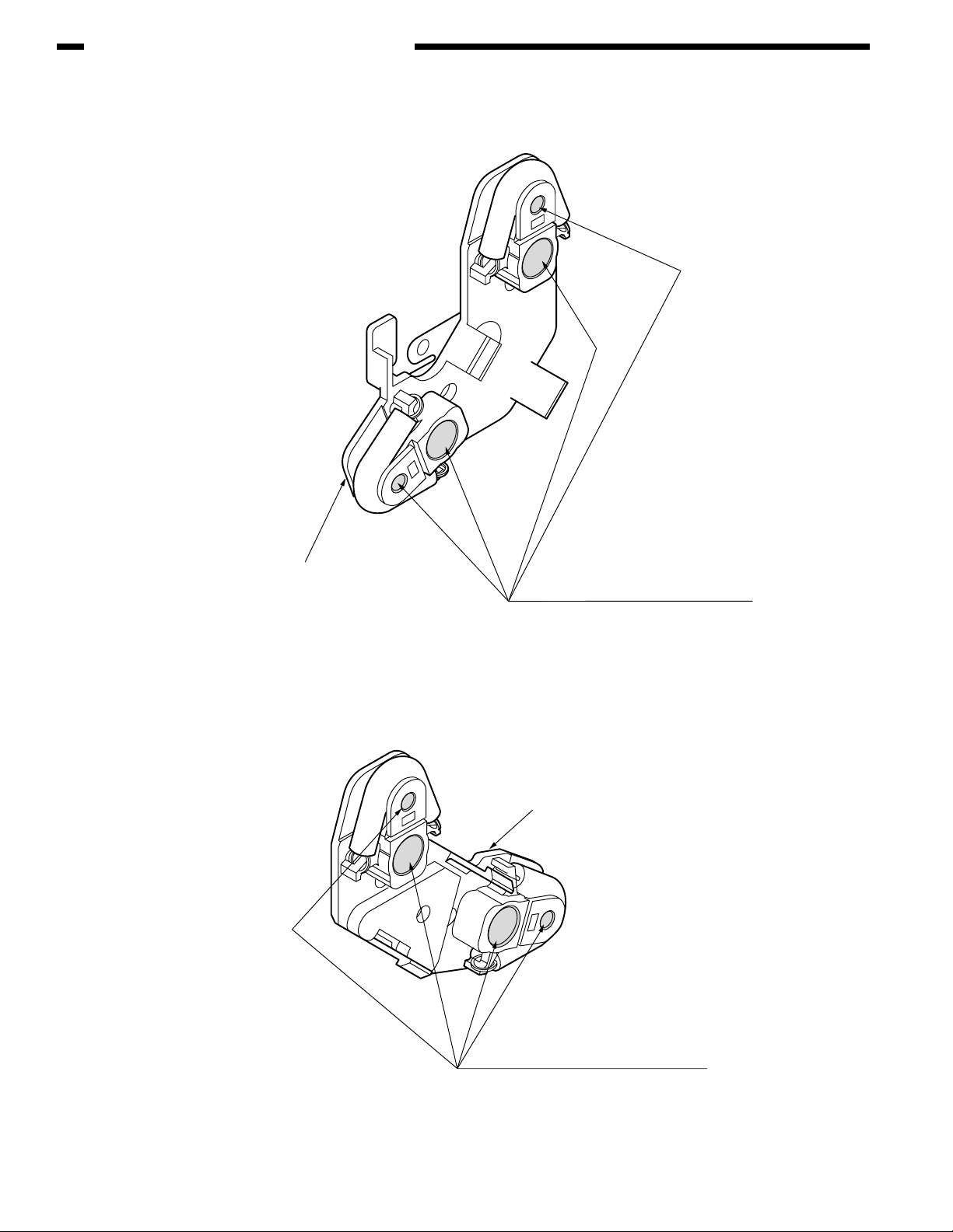
CHAPTER 4 REPLACEMENT OF PARTS
7 0ZZ42071401// Holder Assy.-Regist-L
Holder-Regist-L
8 0ZZ42071901// Holder Assy.-Regist-R
Apply MOLYKOTE (EM-30L) in a normal
quantity to the hatched parts (parts having
the rotation shafts inserted).
EM-30L Class C
Holder-Regist-R
4-34
Apply MOLYKOTE (EM-30L) in a normal
quantity to the hatched parts (parts having
the rotation shafts inserted).
EM-30L Class C
Page 93

9 0ZZ43122601// Fuser-Assy
Cam-Release
Plate-Side-R-Caulking(Fuser)
CHAPTER 4 REPLACEMENT OF PARTS
Lever-Release
Class C
Apply HP-300(normal amount)
to hatched area
Gear-Fuser-(Z35)
Do not apply grease to the boss.
Do not apply grease to the gears.
0 0ZZ43070401// Cassette-Assy
Assemble after applying MOLYKOTE (EM-30L) to the hatched
parts in the illustration below (both right and left).
Gear-Idle-(Z21)
Frame-Separation-Assy
Fulcrums of rotation and side
parts Class C
Grease must not seep out to the paper paths.
4-35
Page 94

CHAPTER 4 REPLACEMENT OF PARTS
A 0ZZ43301501// Guide-Assy.-Eject-L
Apply MOLYKOTE (EM-30L) in a normal quantity to the gear
tooth flanks, shaft surfaces and flanges (6 points).
Grease must not stick to the paper paths.
EM-30L Class C
Shaft-Assy.-Eject(FD)
Apply MOLYKOTE (EM-30L) in a normal
quantity to the bearings (2 points).
EM-30L Class D
Guide-Eject-Upper
Apply MOLYKOTE (EM-30L) in a normal
quantity to the tooth flanks of each gear (3 points).
Apply MOLYKOTE (EM-30L) in a normal
quantity to the post surfaces
(parts having the shaft inserted).
EM-30L Class C
Grease must not stick to the hatched parts,
which compose the paper path.
Detail of part X Detail of part Y
Shaft-Assy.-Fject(FU)
EM-30L Class C
Apply MOLYKOTE (EM-30L) in a normal
quantity to the shaft surfaces (6 points).
Grease must not stick to the paper paths.
part Y part X
EM-30L Class A
4-36
Page 95

B 0ZZ43070201// Frame-Assy.-Base
Apply PM in a small quantity to the hatched part.
(1) Applying method: Wipe the part with a cloth slightly impregnated with PM.
(2) After applying PM, insert and pull out the cassette several times to ensure that no noise is emitted.
PM Class C
CHAPTER 4 REPLACEMENT OF PARTS
Cassette-Assy.
4-37
Page 96

CHAPTER 4 REPLACEMENT OF PARTS
C-1 0ZZ43070101// Printer-Unit
Apply MOLYKOTE (EM-30L) in a normal quantity
to the tips of the terminals (4 points).
EM-30L Class C
Plate-Ass.-Side-L
Applied range of grease (4 points)
4-38
Gear-Idle-Belt
Apply MOLYKOTE (EM-30L)
in a normal quantity to
the end face.
EM-30L Class C
Plate-Driver-PU(Caulking)
Apply MOLYKOTE (EM-30L) in a normal quantity to the post.
EM-30L Class C
Apply MOLYKOTE (EM-30L) in a normal quantity
to the gear tooth flanks.
EM-30L Class C
Page 97

C-2 0ZZ43070101// Printer-Unit
Apply MOLYKOTE (EM-30L) in a normal quantity to the hatched parts.
CHAPTER 4 REPLACEMENT OF PARTS
EM-30L Class C
Plate-Ass.-Side-R
Apply PM to the slot parts of the solid coiling of this
torsion spring using a brush.
(2 places)(At both Sides)
Spring-Torsion-L
Spring-Torsion-R
4-39
Page 98

CHAPTER 4 REPLACEMENT OF PARTS
D 0ZZ43079601PA// Belt-Unit
Apply MOLYKOTE (EM-30L) in a small
quantity to the inside of Bearing-TR
(Belt) (4 points).
EM-30L Class A
Apply MOLYKOTE (EM-30L)
in a normal quantity to the bearings
(both sides).
EM-30L Class C
Enlarged view
4-40
Enlarged view
Apply MOLYKOTE (EM-30L)
in a small quantity to the inside of
Bearing-TR (Belt) (4 points).
EM-30L Class C
Apply MOLYKOTE (EM-30L)
in a normal quantity to the bearings
(both sides).
EM-30L Class A
Apply MOLYKOTE (EM-30L) in a normal quantity
to the sliding face (clearance) between Gear-Drive-Z36
and Gearing-GSB (both sides).
EM-30L ClassA
Page 99

E 0ZZ42626501// Sensor-Assy-Color-Regist
CHAPTER 4 REPLACEMENT OF PARTS
Plate-Sensor-C.Regist
Shaft-Cover-Sensor
Apply MOLYKOTE (EM-30L) in a small quantity to the hatched parts (At both Sides)(8 points).
EM-30L Class A
MOLYKOTE must not stick to the surfaces of Cover Sensor-C. Regist.
Cover-Sensor-C.Regist
4-41
Page 100

CHAPTER 4 REPLACEMENT OF PARTS
F 0ZZ43081301// Roller-Assy.-Idle(FD)
1
2
Disassembled view
Grease applying method:
Before assembling
to the sliding parts (hatched parts) between
2
to 1, apply MOLYKOTE (EM-30L) in a very small quantity (Class S)
1
and 2.
Range in which grease must not stick
4-42
 Loading...