

Page 1
PG-A10X
PG-A10X-SL
AN-A10T
SERVICE MANUAL
SERVICE-ANLEITUNG
S33Y1PG-A10XU
LCD PROJECTOR
LCD PROJEKTOR
PG-A10X
PG-A10X-SL
CEILING MOUNT BRACKET
MODELS
DECKENMONT AGEHALTERUNG
MODELLE
In the interests of user-safety (Required by safety regulations in some countries) the set should be restored
to its original condition and only parts identical to those specified should be used.
Im lnteresse der Benutzersicherheit (erforderliche Sicherheitsregeln in einigen Ländern) muß das Gerät in seinen
Originalzustand gebracht werden. Außerdem dürfen für die spezifizierten Bauteile nur identische Teile verwendet
werden.
AN-A10T
SHARP CORPORATION
This document has been published to be used for
after sales service only.
The contents are subject to change without notice.
1
Page 2

PG-A10X
PG-A10X-SL
AN-A10T
• SPECIFICATIONS ............................................. 3
• IMPORTANT SERVICE SAFETY
NOTES (for USA)............................................... 4
• NOTE TO SERVICE PERSONNEL ................... 5
• OPERATION MANUAL ...................................... 9
• REMOVING OF MAJOR PARTS ..................... 16
• RESETTING THE TOT AL LAMP TIMER ......... 20
• THE OPTICAL UNIT OUTLINE........................ 21
• ELECTRICAL ADJUSTMENT.......................... 23
• TROUBLE SHOOTING TABLE........................ 31
• CHASSIS LAYOUT .......................................... 70
• BLOCK DIAGRAM ........................................... 72
CONTENTS
Page Page
• OVERALL WIRING DIAGRAM ........................ 74
• DESCRIPTION OF SCHEMATIC DIAGRAM... 76
• WAVEFORMS .................................................. 77
• SCHEMATIC DIAGRAM .................................. 78
• PRINTED WIRING BOARD ASSEMBLIES ... 105
• P ARTS LIST
Ë
ELECTRICAL PARTS............................... 108
Ë
CABINET AND MECHANICAL PARTS .... 120
Ë
ACCESSORIES PARTS........................... 124
Ë
P ACKING PARTS..................................... 124
• PACKING OF THE SET ................................. 125
CEILING MOUNT BRACKET (AN-A10T) ...... 126
Seite Seite
• TECHNISCHE DATEN..................................... 38
• HINWEISE FÜR DAS
WARTUNGSPERSONAL................................. 39
• BEDIENUNGSANLEITUNG............................. 41
• ENTFERNEN DER HAUPTTEILE ................... 48
• RÜCKSTELLEN DES
LAMPENBETRIEBSZEIT-TIMERS.................. 52
• BESCHREIBUNG DER OPTIK-EINHEIT ........ 53
• ELEKTRISCHE EINSTELLUNG ...................... 55
• FEHLERSUCHTABELLE ................................. 63
• CHASSIS-ANORDNUNG ................................ 70
• BLOCKSCHALTBILD ....................................... 72
• GESAMTSCHALTPLAN................................... 74
INHALT
• BESCHREIBUNG DES SCHEMATISCHEN
• WELLENFORMEN........................................... 77
• SCHEMATISCHER SCHALTPLAN.................. 78
• LEITERPLATTENEINHEITEN ....................... 105
• ERSATZTEILLISTE
• VERPACKEN DES GERÄTS ......................... 125
SCHALTPLANS ............................................... 76
Ë
ELEKTRISCHE BAUTEILE ...................... 108
Ë
CEHÄUSE UND MECHANISCHE
BAUTEILE ................................................ 120
Ë
ZUBEHÖRTEILE...................................... 124
Ë
VERPACKUNGSTEILE ............................ 124
DECKENMONTAGEHALTERUNG
(AN-A10T)...................................................... 126
2
Page 3

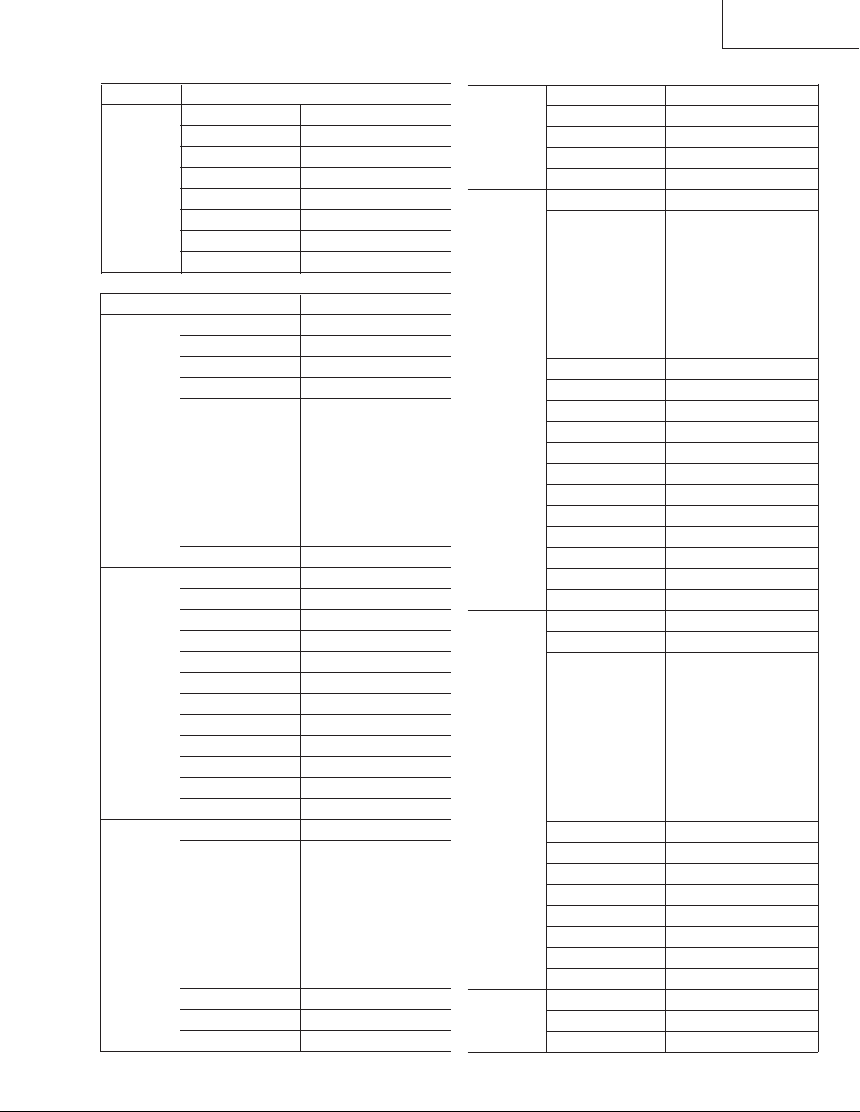
Specifications
Product type LCD Projector
Model PG-A10X/PG-A10X-SL
Video system NTSC3.58/NTSC4.43/PAL/PAL-M/PAL-N/PAL-60/SECAM/
Display method LCD panel ✕ 3, RGB optical shutter method
LCD panel Panel size: 0.79" (20.0 mm) (12 [H] ✕ 16 [W] mm)
Standard lens 1 – 1.2✕ zoom lens, F1.9 – 2.2, f = 26 – 31 mm
Projection lamp SHP 165 W lamp
Component input signal 15-pin mini D-sub connector
(INPUT1) Y: 1.0 Vp-p, sync negative, 75 Ω terminated
Horizontal resolution 700 TV lines (DTV720P)
Computer RGB input signal 15-pin mini D-sub connector
(INPUT 1) RGB separate/sync on green type analog input: 0 – 0.7 Vp-p, positive, 75 Ω terminated
S-video input signal 4-pin mini DIN connector
(INPUT 2) Y (luminance signal): 1.0 Vp-p, sync negative, 75 Ω terminated
Video input signal RCA connector: VIDEO, composite video, 1.0 Vp-p, sync negative, 75 Ω
(INPUT 3) terminated
Computer control signal (RS-232C)
Pixel clock 12 – 108 MHz
Vertical frequency 43 – 85 Hz
Horizontal frequency 15 – 70 kHz
Audio input signal ø 3.5 mm minijack: AUDIO, 0.5 Vrms, more than 47 kΩ (stereo)
Audio output 1.0 W (monaural)
Speaker system 2.8 cm round ✕ 1
Rated voltage AC 100 – 240 V
Input current 2.4 A
Rated frequency 50/60 Hz
Power consumption 240 W (Standard mode)/190 W (Eco mode) with AC 100 V
Power consumption 5 W (AC 100 V) — 8 W (AC 240 V)
(standby) 900 BTU/hour (Standard mode)/710 BTU/hour (Eco mode) with AC 100 V
Heat dissipation 850 BTU/hour (Standard mode)/680 BTU/hour (Eco mode) with AC 240 V
Operating temperature 41°F to 95°F (+5°C to +35°C)
Storage temperature – 4°F to 140°F ( – 20°C to +60°C)
Cabinet Plastic
I/R carrier frequency 38 kHz
Dimensions (approx.) 11 45/64" ✕ 3 13/64" ✕ 9 1/32" (297 (W) ✕ 81 (H) ✕ 229 (D) mm) (main body only)
Weight (approx.) 6.4 lbs. (2.9 kg)
Supplied accessories Remote control, Two R-6 batteries, Power cord for U.S., Canada etc. (6', 1.8 m), Power cord for Europe,
Replacement parts Lamp unit (Lamp/cage module) (BQC-PGA10X//1), Remote control (RRMCGA138WJSA), Two R-6 bat-
DTV480I/DTV480P/DTV540P/DTV580I/DTV580P/DTV720P/DTV1035I/DTV1080I
No. of dots: 786,432 dots (1,024 [H] ✕ 768 [V])
B: 0.7 Vp-p, 75 Ω terminated
P
R: 0.7 Vp-p, 75 Ω terminated
P
HORIZONTAL SYNC. SIGNAL: TTL level (positive/negative)
VERTICAL SYNC. SIGNAL: Same as above
C (chrominance signal): Burst 0.286 Vp-p, 75 Ω terminated
9-pin mini DIN connector
226 W (Standard mode)/182 W (Eco mode) with AC 240 V
11 45/64" ✕ 3 33/64" ✕ 9 1/32" (297 (W) ✕ 89 (H) ✕ 229 (D) mm) (including adjustment foot and
projecting parts)
except U.K. (6', 1.8 m), Power cord for U.K., Hong Kong and Singapore (6', 1.8 m), Power cord for
Australia, New Zealand and Oceania (6', 1.8 m), RGB cable (9'10", 3.0 m), DIN-D-sub RS-232C adaptor
(5 57/64", 15 cm), Carrying case, Lens cap (attached), Extra air filter, Projector manual and technical
reference CD-ROM, “QUICK GUIDE” label, Operation manual
teries ("AA" size, UM/SUM-3, HP-7, or similar), Power cord for U.S., Canada etc. (QACCDA016WJPZ),
Power cord for Europe, except U.K. (QACCV A006WJPZ), Power cord for U.K., Hong Kong and Singapore
(QACCBA015WJPZ), Power cord for Australia, New Zealand and Oceania (QACCLA005WJPZ), RGB
cable (QCNWGA012WJPZ), DIN-D-sub RS-232C adaptor (QCNWGA015WJPZ), Carrying case
(GCASNA006WJSA), Lens cap (CCAPHA007WJ01), Air filter (PFILDA008WJZZ), Projector manual
and technical reference CD-ROM (UDSKAA022WJN1), “QUICK GUIDE” label (TLABZA191WJZZ), Operation manual (TINS-A505WJN1)
PG-A10X
PG-A10X-SL
AN-A10T
This SHARP projector uses an LCD (Liquid Crystal Display) panel.
This very sophisticated panel contains 786,432 pixels ( ✕ RGB)
TFT s (Thin Film T ransistors). As with any high technology electronic
equipment such as large screen TVs, video systems and video cameras, there are certain acceptable tolerances that the equipment
must conform to.
Specifications are subject to change without notice.
This unit has some inactive pixels within acceptable tolerances which
may result in inactive dots on the picture screen. This will not affect
the picture quality or the life expectancy of the unit.
3
Page 4
PG-A10X
2
2
PG-A10X-SL
AN-A10T
IMPORTANT SERVICE SAFETY NOTES (for USA)
Ë Service work should be performed only by qualified service technicians who are
thoroughly familiar with all safety checks and servicing guidelines as follows:
WARNING
1. For continued safety, no modification of any circuit
should be attempted.
2. Disconnect AC power before servicing.
BEFORE RETURNING THE PROJECTOR:
(Fire & Shock Hazard)
Before returning the projector to the user, perform
the following safety checks:
1. Inspect lead wires are not pinched between the
chassis and other metal parts of the projector.
2. Inspect all protective devices such as non-metallic
control knobs, insulating materials, cabinet backs,
adjustment and compartment covers or shields,
isolation resistor-capacity networks, mechanical
insulators, etc.
3. To be sure that no shock hazard exists, check for
current leakage in the following manner:
» Plug the AC cord directly into a 120-volt AC outlet,
(Do not use an isolation transformer for this test).
» Using two clip leads, connect a 1.5k ohm, 10 watt
resistor paralleled by a 0.15µF capacitor in parallel
between all exposed metal cabinet parts and earth
ground.
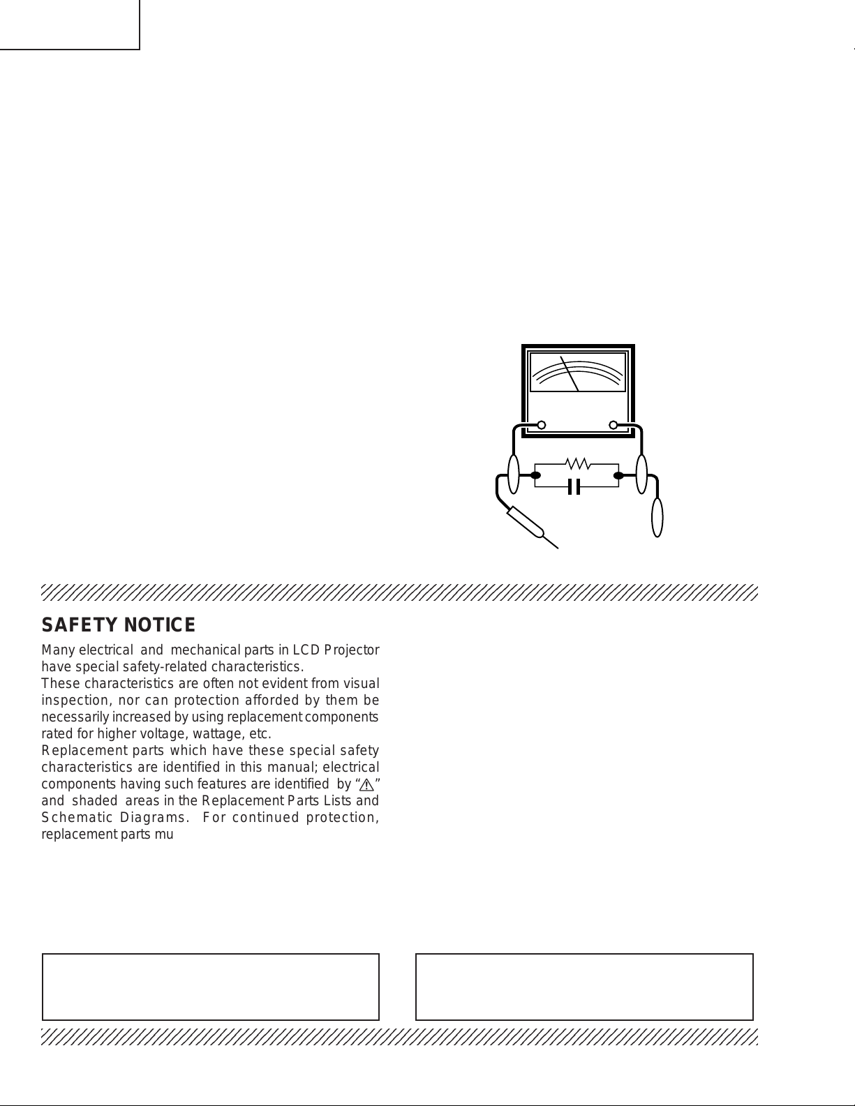
» Use an AC voltmeter with sensitivity of 5000 ohm per
volt., or higher, sensitivity to measure the AC voltage
drop across the resistor (See Diagram).
» All checks must be repeated with the AC plug
connection reversed. (If necessary , a non-polarized
adapter plug must be used only for the purpose of
completing these checks.)
Any reading of 0.3 volts RMS (this corresponds to
0.2 milliamp. AC.) or more is excessive and indicates
a potential shock hazard which must be corrected
before returning the unit to the owner.
AC
VOLTMETER
1.5k ohm (10W)
0.15µF
TEST PROBE
TO EXPOSED
METAL PARTS
CONNECT TO KNOWN
EARTH GROUND
234567890123456789012345678901212345678901234567890123456789012123456789012345678901234567890121
SAFETY NOTICE
Many electrical and mechanical parts in LCD Projector
have special safety-related characteristics.
These characteristics are often not evident from visual
inspection, nor can protection afforded by them be
necessarily increased by using replacement components
rated for higher voltage, wattage, etc.
Replacement parts which have these special safety
characteristics are identified in this manual; electrical
components having such features are identified by “å”
and shaded areas in the Replacement Parts Lists and
Schematic Diagrams. For continued protection,
replacement parts must be identical to those used in the
original circuit. The use of a substitute replacement parts
which do not have the same safety characteristics as
the factory recommended replacement parts shown in
this service manual, may create shock, fire or other
hazards.
AVIS POUR LA SECURITE
De nombreuses pièces, électriques et mécaniques, dans
les projecteur à LCD présentent des caractéristiques
spéciales relatives à la sécurité, qui ne sont souvent
pas évidentes à vue.
Le degré de protection ne peut pas être nécessairement
augmentée en utilisant des pièces de remplacement
étalonnées pour haute tension, puissance, etc.
Les pièces de remplacement qui présentent ces
caractéristiques sont identifiées dans ce manuel;
les pièces électriques qui présentent ces particularités
sont identifiées par la marque “å” et hachurées dans la
liste des pièces de remplacement et les diagrammes
schématiques. Pour assurer la protection, ces pièces
doivent être identiques à celles utilisées dans le circuit
d’origine. L’utilisation de pièces qui n’ont pas les mêmes
caractéristiques que les pièces recommandées par
l’usine, indiquées dans ce manuel, peut provoquer des
électrocutions, incendies ou autres accidents.
WARNING: The bimetallic component has the primary
conductive side exposed. Be very careful in
handling this component when the power is on.
234567890123456789012345678901212345678901234567890123456789012123456789012345678901234567890121
AVERTISSEMENT: La composante bimétallique dispose du
conducteur primaire dénudé. Faire
attention lors de la manipulation de cette
composante sous tension.
4
Page 5
PG-A10X
PG-A10X-SL
AN-A10T
NOTE TO SERVICE
PERSONNEL
UV-RADIATION PRECAUTION
The light source, UHP lamp, in the LCD projector
emits small amounts of UV-Radiation.
A VOID DIRECT EYE AND SKIN EXPOSURE.
To ensure safety please adhere to the following:
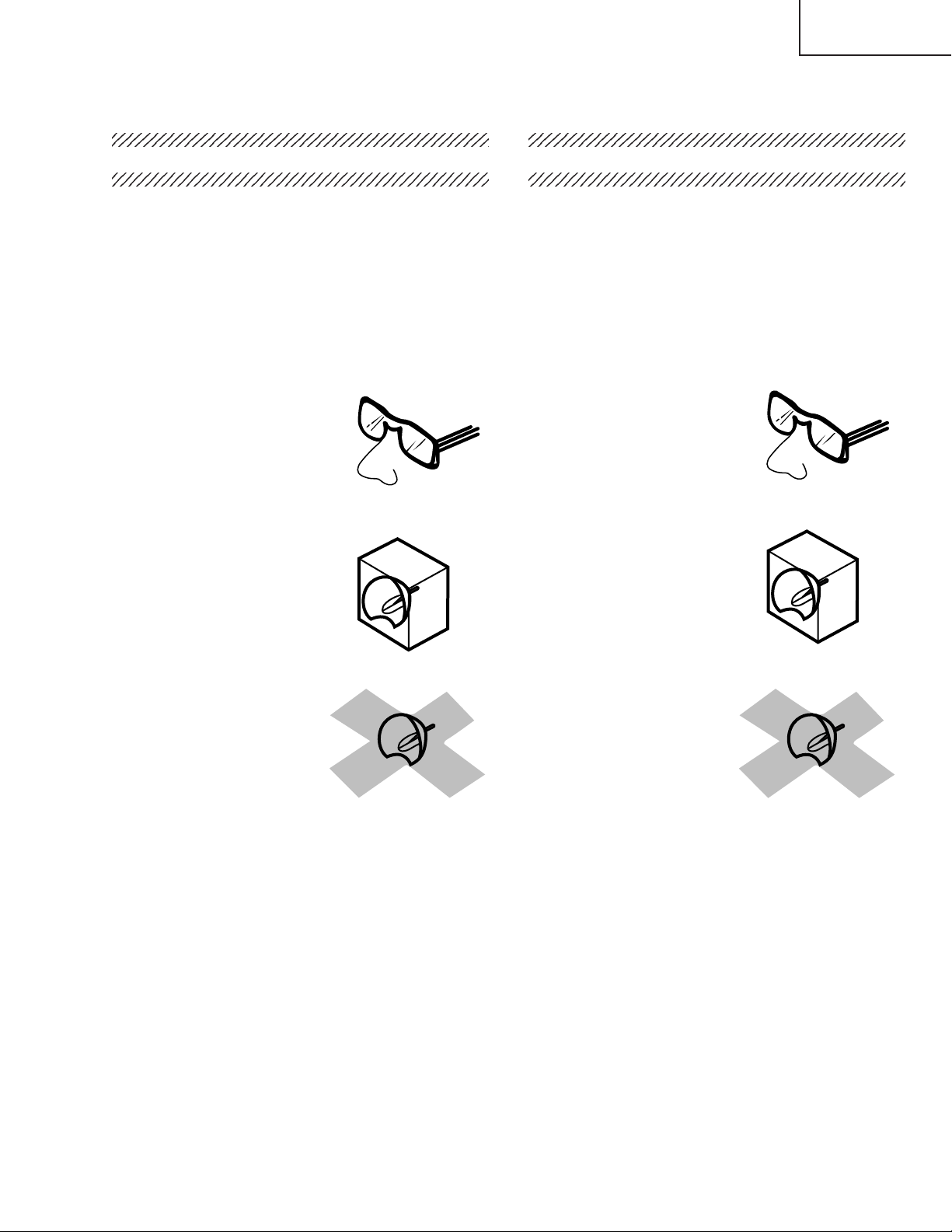
1. Be sure to wear sun-glasses when servicing the
projector with the lamp
turned “on” and the top
enclosure removed.
2. Do not operate the lamp outside of the lamp housing.
NOTE POUR LE PERSONNEL
D’ENTRETIEN
PRECAUTION POUR LES RADIA TIONS UV
La source de lumière, la lampe UHP, dans le
projecteur LCD émet de petites quantités de
radiation UV.
EVITEZ TOUTE EXPOSITION DIRECTE
DES YEUX ET DE LA PEAU.
Pour votre sécurité, nous vous prions de respecter
les points suivants:
1. Toujours porter des lunettes de soleil lors d’un
entretien du projecteur
avec la lampe allumée
et le haut du coffret retiré.
2. Ne pas faire fonctionner la lampe à l’extérieur du
boîtier de lampe.
3. Do not operate for more than 2 hours with the
enclosure removed.
UV-Radiation and Medium Pressure
Lamp Precautions
1. Be sure to disconnect the AC plug when replacing
the lamp.
2. Allow one hour for the unit to cool down before
servicing.
3. Replace only with same type lamp. Type BQCPGA10X//1 rated 100V/200W.
4. The lamp emits small amounts of UV-Radiation, avoid
direct-eye contact.
5. The medium pressure lamp involves a risk of
explosion. Be sure to follow installation instructions
described below and handle the lamp with care.
3. Ne pas faire fonctionner plus de 2 heures avec le
coffret retiré.
Précautions pour les radiations UV
et la lampe moyenne pression
1. Toujours débrancher la fiche AC lors du
remplacement de la lampe.
2. Laisser l’unité refroidir pendant une heure avant de
procéder à l’entretien.
3. Ne remplacer qu’avec une lampe du même type.
Type BQC-PGA10X//1, caractéristique 100V/200W.
4. La lampe émet de petites quantités de radiation UVéviter tout contact direct avec les yeux.
5. La lampe moyenne pression implique un risque
d’explosion. Toujours suivre les instructions
d’installation décrites ci-dessous et manipuler la
lampe avec soin.
5
Page 6
PG-A10X
5
4
5
5
PG-A10X-SL
AN-A10T
234567890123456789012345678901212345678901234
234567890123456789012345678901212345678901234
UV-RADIATION PRECAUTION (Continued)
23456789012345678901234567890121234567890123
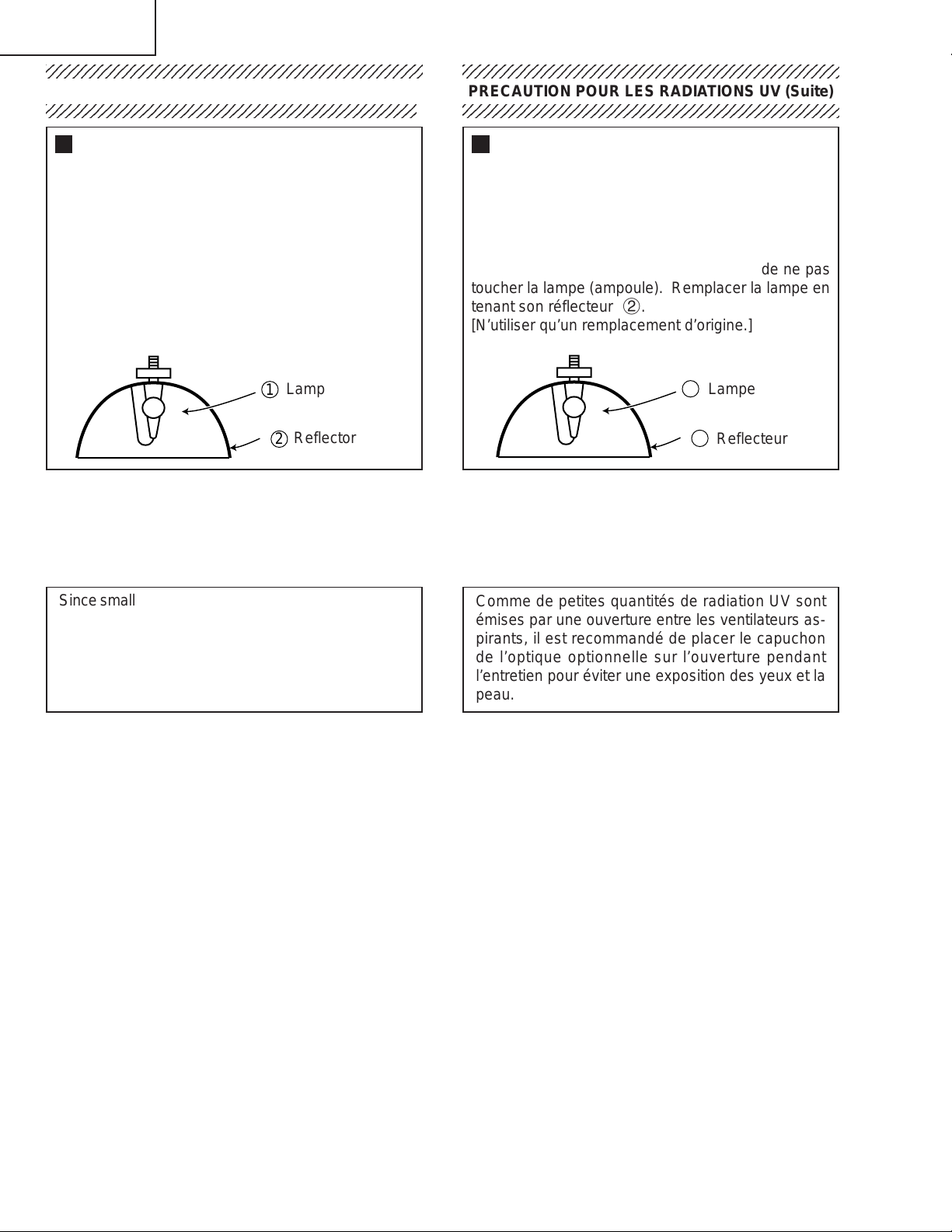
Lamp Replacement
Note:
Since the lamp reaches a very high temperature
during units operation replacement of the lamp
should be done at least one hour after the power
has been turned off. (to allow the lamp to cool off.)
Installing the new lamp, make sure not to touch the
lamp (bulb) replace the lamp by holding its reflector
2.
[Use original replacement only.]
Lamp
1
Reflector
2
DANGER ! –– Never turn the power on without the
lamp to avoid electric-shock or damage of the
devices since the stabilizer generates high voltages
at its start.
PRECAUTION POUR LES RADIATIONS UV (Suite)
234567890123456789012345678901212345678901234
Remplacement de la lampe
Remarque:
Comme la lampe devient très chaude pendant le
fonctionnement de l’unité, son remplacement ne doit
être effectué au moins une heure après avoir coupé
l’alimentation (pour permettre à la lampe de refroidir).
En installant la nouvelle lampe, s’assurer de ne pas
toucher la lampe (ampoule). Remplacer la lampe en
tenant son réflecteur 2.
[N’utiliser qu’un remplacement d’origine.]
1
Lampe
2
Reflecteur
DANGER ! –– Ne jamais mettre sous tension sans
la lampe pour éviter un choc électrique ou des
dommages des appareils car le stabilisateur génère
de hautes tensions à sa mise en route.
Since small amounts of UV-radiation are emitted from
an opening between the exhaust fans, it is recommended to place the cap of the optional lens on the
opening during servicing to avoid eye and skin exposure.
Comme de petites quantités de radiation UV sont
émises par une ouverture entre les ventilateurs aspirants, il est recommandé de placer le capuchon
de l’optique optionnelle sur l’ouverture pendant
l’entretien pour éviter une exposition des yeux et la
peau.
6
Page 7
PG-A10X
12345678901234567890123456789012123456789012345678901234567890121234567890123456789012345678901212
12345678901234567890123456789012123456789012345678901234567890121234567890123456789012345678901212
PG-A10X-SL
AN-A10T
WARNING: High brightness light source, do not stare into the beam of light, or view directly . Be especially
careful that children do not stare directly in to the beam of light.
WARNING: TO REDUCE THE RISK OF FIRE OR ELECTRIC SHOCK, DO NOT EXPOSE THIS UNIT TO
MOISTURE OR WET LOCATIONS.
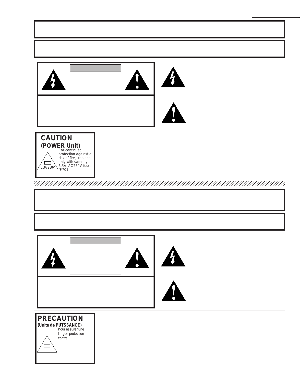
CAUTION
RISK OF ELECTRIC SHOCK.
DO NOT REMOVE SCREWS
EXCEPT SPECIFIED USER
SERVICE SCREW
CAUTION: TO REDUCE THE RISK OF ELECTRIC SHOCK,
DO NOT REMOVE CABINET .
NO USER-SERVICEABLE P ARTS EXCEPT LAMP UNIT.
REFER SERVICING TO QUALIFIED SERVICE
PERSONNEL.
The lighting flash with arrowhead within a
triangle is intended to tell the user that
parts inside the product are risk of electric
shock to persons.
The exclamation point within a triangle is
intended to tell the user that important
operating and servicing instructions are in
the manual with the projector.
CAUTION
(POWER Unit)
6.3A 250V
AVERTISSEMENT: Source lumineuse de grande intensité. Ne pas fixer le faisceau lumineux ou le regarder
For continued
protection against a
risk of fire, replace
only with same type
6.3A, AC250V fuse.
(F701)
directement. Veiller particulièrement à éviter que les enfants ne fixent directement le
faisceau lumineux.
AVERTISSEMENT: AFIN D’EVITER TOUT RISQUE D’INCENDIE OU D’ELECTROCUTION, NE PAS PLACER
CET APPAREIL DANS UN ENDROIT HUMIDE OU MOUILLE.
ATTENTION
RISQUE
D’ELECTROCUTION NE
PASRETIRER LES VIS, A
L’EXCEPTION DES VIS DE
REPARATION UTILISATEUR
SPECIFIEES
L’éclair terminé d’une flèche à l’intérieur
d’un triangle indique à l’utilisateur que les
pi‘eces se trouvant dans l’appareil sont
susceptibles de provoquer une décharge
électrique.
Le point d’exclamation à l’intérieur d’un
ATTENTION: POUR EVITER TOUT RISQUE
D’ELECTROCUTION, NE PAS RETIRER LE CAPOT.
AUCUNE DES PIECES INTERIEURES N’EST REP ARABLE
PAR L’UTILISA TEUR, A L’EXCEPTION DE L’UNITE DE
LAMPE. POUR TOUTE REP ARATION, S’ADRESSER A UN
TECHNICIEN D’ENTRETIEN QUALIFIE.
triangle indique à l’utilisateur que les
instructions de fonctionnement et
d’entretien sont détaillées dans les
documents fournis avec le projecteur.
PRECAUTION
(Unité de PUTSSANCE)
6.3A 250V
Pour assurer une
longue protection
contre l'incendie,
utiliser seulement un
fusible de même type
(6,3A, 250V CA).
(F701)
7
Page 8
PG-A10X
PG-A10X-SL
AN-A10T
Precautions for using lead-free solder
1 Employing lead-free solder
"Main and R/C Receiver PWBs" of these models employs lead-free solder. The LF symbol indicates lead-free
solder, and is attached on the PWBs and service manuals. The alphabetical character following LF shows the type
of lead-free solder.
Example:
L Fa
Indicates lead-free solder of tin, silver and copper.
2 Using lead-free wire solder
When fixing the PWB soldered with the lead-free solder, apply lead-free wire solder. Repairing with conventional
lead wire solder may cause damage or accident due to cracks.
As the melting point of lead-free solder (Sn-Ag-Cu) is higher than the lead wire solder by 40°C, we recommend you
to use a dedicated soldering bit, if you are not familiar with how to obtain lead-free wire solder or soldening bit,
contact our service station or service ranch in your area.
3 Soldering
As the melting point of lead-free solder (Sn-Ag-Cu) is about 220°C which is higher than the conventional lead solder
by 40°C, and as it has poor solder wettabillty, you may be apt to keep the soldering bit in contact with the PWB for
extended period of time. However, Since the land may be peeled off or the maximum heat-resistance temperature
of parts may be excoeded, remove the bit from the PWB as soon as you conurm the steady soldering condition.
Lead-free solder contains more tin, and the end of the soldering bit may be easily corroded. Make sure to tum on
and off the power of the bit as required.
if a different type of solder stays on the tip of the soldering bit, it is alloyed with lead-free solder. Clean the bit after
every use of it.
When the tip of the soldering bit is blackened during use, file it with steel wool or fine sandpaper.
Becareful when replacing parts with polarity indication on the PWB silk.
Lead-free wire solder for servicing
Part No. ★ Description Code
ZHNDAi123250E J φ0.3mm 250g(1roll) BL
ZHNDAi126500E J φ0.6mm 500g(1roll) BK
ZHNDAi12801KE J φ1.0mm 1kg(1roll) BM
8
Page 9
Operation Manual
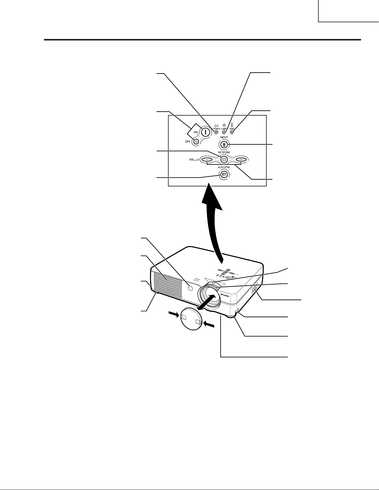
Projector (Front and Top View)
PG-A10X
PG-A10X-SL
AN-A10T
Power indicator
Illuminates red when the
projector is in standby.
When the power is turned
on, this indicator will
illuminate green.
Power ON/OFF
buttons
For turning the power on or off.
KEYSTONE button
For entering the Keystone
Correction mode.
AUTO SYNC button
For automatically
adjusting images when
connected to a computer.
Remote control
sensor
Lamp replacement
indicator
Illuminates green indicating
normal function. Replace
the lamp when the indicator
illuminates red.
Temperature warning
indicator
When the internal
temperature rises, this
indicator will illuminate red.
INPUT button
For switching input mode
1, 2 or 3.
Volume buttons
For adjusting the speaker
sound level or the
Keystone Correction.
Exhaust vent
Foot release
(on the side of
the projector)
Front adjustment foot
Attaching and removing the lens cap
•
Press on the two buttons of the lens cap
and attach it to the lens, then release the
buttons to lock it in place.
•
Press on the two buttons of the lens cap
and remove it from the lens.
Zoom knob
Focus ring
Speaker
Foot release
Front adjustment
foot
Air filter/cooling
fan (Intake vent)
(on the bottom of
the projector)
9
Page 10
PG-A10X
j
)
PG-A10X-SL
AN-A10T
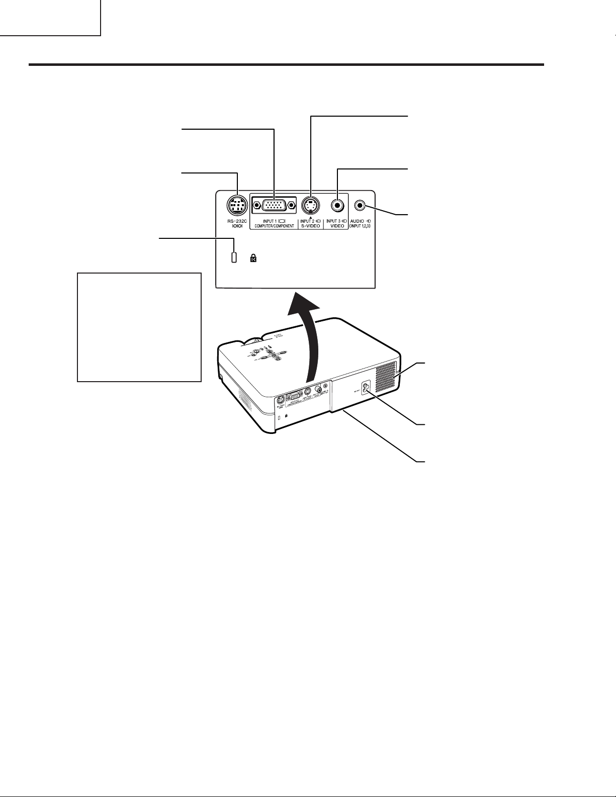
Projector (Rear View)
INPUT 1 terminal
Terminal for
computer RGB and
component signals.
RS-232C terminal
For controlling
the projector using a
computer.
Kensington Security
Standard connector
Using the Kensington Lock
• This projector has a
Kensington Security Standard connector for use with
a Kensington MicroSaver
Security System. Refer to
the information that came
with the system for instructions on how to use it to secure the projector.
INPUT 2 terminal
Terminal for
connecting video
equipment with an
S-video terminal.
INPUT 3 terminal
Terminal for
connecting video
equipment.
AUDIO INPUT
terminal
Shared audio input
terminal for INPUT
1, 2 and 3.
Intake vent
AC socket
Rear adjustment
foot
(on the bottom of
the pro
ector
10
Page 11
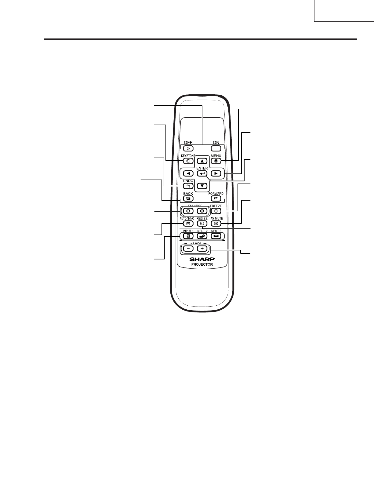
Remote Control (Front View)
PG-A10X
PG-A10X-SL
AN-A10T
Power ON/OFF buttons
For turning the power on or off.
KEYSTONE button
For entering the Keystone
Correction mode.
UNDO button
For undoing an operation or
returning to the previous display.
FORWARD/BACK buttons
Same function as the [Page Down]
and [Page Up] keys on a computer
keyboard when using the Remote
Receiver (optional).
ENLARGE (Enlarge/Reduce)
buttons
For enlarging or reducing part of
the image.
AUTO SYNC button
For automatically adjusting images
when connected to a computer.
INPUT buttons
For switching to the respective
input modes.
MENU button
For displaying adjustment and
setting screens.
Adjustment buttons
(', ", \, |)
For selecting menu items.
ENTER button
For setting items selected or
adjusted on the menu.
FREEZE button
For freezing images.
AV MUTE button
For temporarily displaying the
black screen and turning off the
sound.
RESIZE button
For switching the screen size
(NORMAL, BORDER, etc).
Volume buttons
For adjusting the speaker sound
level.
11
Page 12
PG-A10X
PG-A10X-SL
AN-A10T
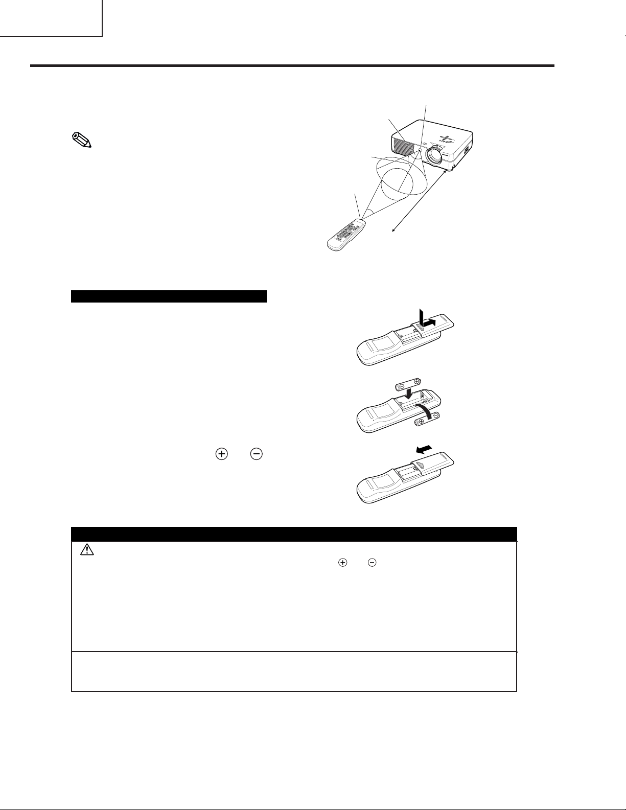
Usable Range
■ The remote control can be used to contr ol
• The signal from the remote control can be re-
When using the remote control:
• Be sure not to drop, expose to moisture or high
• The remote control may malfunction under a
the projector within the ranges shown in
the illustration.
Note
flected off a screen for easy operation. However, the effective distance of the signal may
differ depending on the screen material.
temperature.
fluorescent lamp. In this case, move the pro-
jector away from the fluorescent lamp.
Remote
control
signal
transmitters
30°
Remote control
30°
Remote control sensor
45°
23' (7 m)
Inserting the Batteries
The batteries (two R-6 batteries (“AA” siz e, UM/
SUM-3, HP-7 or similar)) are supplied in the
package.
1
Press the ▲ mark on the cover
and slide it in the direction of the
arrow .
2
Insert the batteries.
• Insert the batteries making sure the polarities correctly match the
marks inside the battery compar tment.
3
Attach the cover and slide it until it clicks into place.
Incorrect use of the batteries may cause them to leak or explode. Please follow the precautions below.
Caution
• Insert the batteries making sure the polarities correctly match the and marks inside the battery compartment.
• Batteries of different types have different properties, therefore do not mix batteries of different types.
• Do not mix new and old batteries.
This may shorten the life of new batteries or may cause old batteries to leak.
• Remove the batteries from the remote control once they have run out, as leaving them in can cause them to leak.
Battery fluid from leaked batteries is harmful to skin, therefore be sure to first wipe them and then remove them
using a cloth.
and
• The batteries included with this projector may run down in a short period, depending on how they are kept. Be
sure to replace them as soon as possible with new batteries.
• Remove the batteries from the remote control if you will not be using the remote control for a long time.
12
Page 13
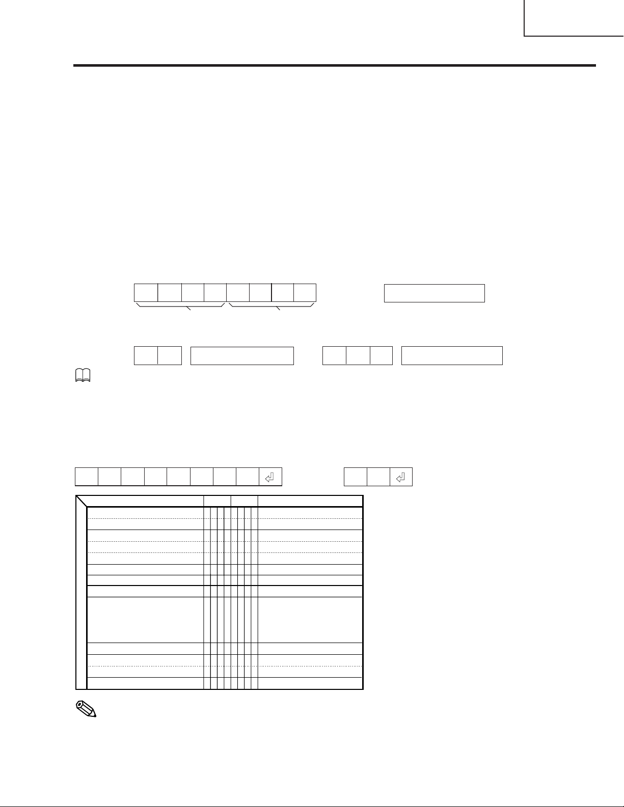
RS-232C Specifications and Command Settings
PC control
A computer can be used to control the projector by connecting an RS-232C serial control cab le (cross type,
sold separately) to the projector.
Communication conditions
Set the serial port settings of the computer to match that of the table.
Signal format: Conforms to RS-232C standard.
Baud rate: 9,600 bps
Data length: 8 bits
Parity bit: None
Stop bit: 1 bit
Flow control: None
Basic format
Commands from the computer are sent in the following order: command, parameter, and return code. After
the projector processes the command from the computer, it sends a response code to the computer.
Command format
C1 C2 C3 C4 P1 P2 P3 P4
Return code (
0DH
)
PG-A10X
PG-A10X-SL
AN-A10T
Command 4-digit Parameter 4-digit
Response code format
Normal response
O K E R R
Return code (
0DH
Problem response (communication error or incorrect command)
0DH
)
Return code (
)
Info
• When more than one code is being sent, send each command only after the response code for the previous
command from the projector is verified.
Commands
Example: When turning on the projector, make the following setting.
ProjectorComputer
POWR _1__ OK
CONTROL CONTENTS
Power Off (Standby)
Power On
INPUT1
INPUT2
INPUT3
Lamp Usage Time (hour)
Remaining Lamp Life (Percentage)
Lamp Status
Unit Status
BUTTONS & REMOTE CONTROL KEY
Model Name Check
AV Mute Off
AV Mute On
Auto Sync Start
COMMAND
P
O
W
R
P
O
W
R
I
R
G
B
I
V
E
D
I
V
E
D
T
L
T
T
T
L
T
L
T
L
P
S
T
A
B
N
T
N
A
M
I
M
B
K
I
M
B
K
A
D
J
S
PARAMETER
OK or ERR
_
_
_
0
OK or ERR
_
_
_
1
OK or ERR
_
_
_
1
OK or ERR
_
_
_
1
OK or ERR
_
_
_
2
0~9999
_
_
_
1
0~100
_
_
_
1
0:Off, 1:On, 2:Retry, 3:Waiting, 4:Lamp Error
_
_
_
1
0:Normal, 1:Temp High, 2:Fan Err,
_
_
_
1
4:Filter Cover Err, 8:Lamp 100 hours,
16:Lamp Burnt-out, 32:Lamp Not Lit,
64:Temp Abnormally High
PROJECTOR NAME
_
_
_
1
OK or ERR
_
_
_
0
OK or ERR
_
_
_
1
OK or ERR
_
_
_
1
→
←
RETURN
Note
• If an underbar (_) appears in the parameter column, enter a space. If an asterisk (*) appears, enter a
value in the range indicated in brackets under CONTROL CONTENTS.
13
Page 14
PG-A10X
PG-A10X-SL
AN-A10T
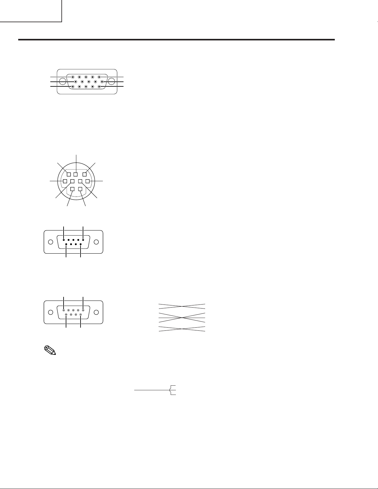
Connection Pin Assignments
INPUT 1 RGB Signal Terminal: 15-pin Mini D-sub female connector
RGB Input
5
10
15
RS-232C Terminal: 9-pin Mini DIN female connector
8
9
6
5
7
3
4
21
9-pin D-sub male connector of the DIN-D-sub RS-232C adaptor
15
69
1
6
11
10. GND
11. Not connected
12. Bi-directional data
13. Horizontal sync signal
14. Vertical sync signal
15. Data clock
Pin No. Signal Name I/O Reference
1 Not connected
2 RD Receive Data Input Connected to internal circuit
3 SD Send Data Output Connected to internal circuit
4 Not connected
5 SG Signal Ground Connected to internal circuit
6 Not connected
7 Not connected
8 Not connected
9 Not connected
Pin No. Signal Name I/O Reference
1 Not connected
2 RD Receive Data Input Connected to internal circuit
3 SD Send Data Output Connected to internal circuit
4 Not connected
5 SG Signal Ground Connected to internal circuit
6 Not connected
7 Not connected
8 Not connected
9 Not connected
1. Video input (red)
2. Video input (green/sync on green)
3. Video input (blue)
4. Not connected
5. Not connected
6. Earth (red)
7. Earth (green/sync on green)
8. Earth (blue)
9. Not connected
Component Input
1. PR (CR)
2. Y
B (CB)
3. P
4. Not connected
5. Not connected
6. Earth (P
7. Earth (Y)
8. Earth (P
9. Not connected
10. Not connected
11. Not connected
12. Not connected
13. Not connected
14. Not connected
15. Not connected
R)
B)
RS-232C Cable recommended connection: 9-pin D-sub female connector
51
96
Pin No. Signal Pin No. Signal
1CD 1 CD
2RD 2 RD
3SD 3 SD
4ER 4 ER
5SG 5 SG
6DR 6 DR
7RS 7 RS
8CS 8 CS
9CI 9 CI
Note
• Depending on the controlling device used, it may be necessary to connect Pin 4 and Pin 6 on the controlling
device (e.g. PC).
Projector
Pin No.
4
5
6
PC
Pin No.
4
5
6
14
Page 15
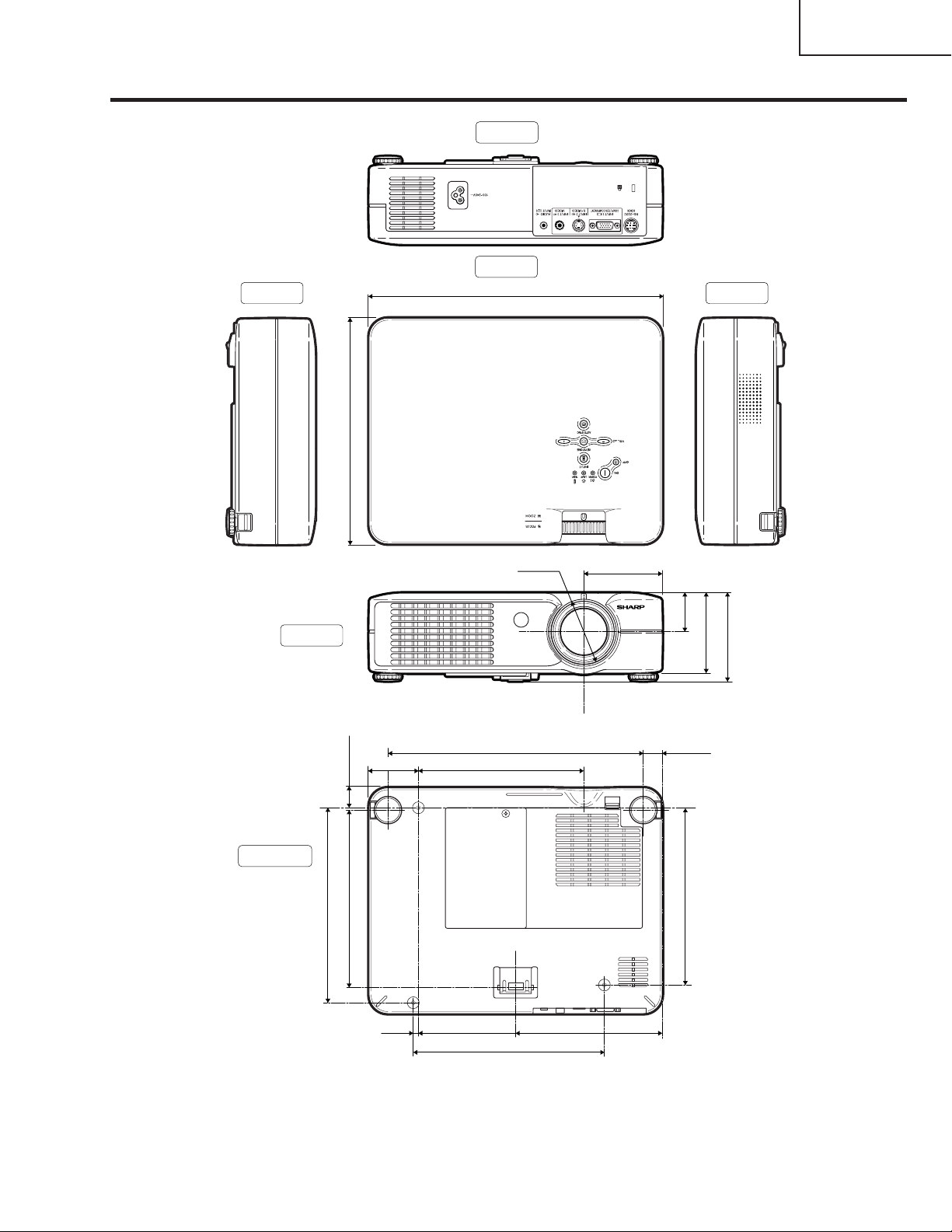
Dimensions
Side View Side View
(229)
32
/
1
9
Rear View
Top View
45
/64 (297)
11
PG-A10X
PG-A10X-SL
AN-A10T
Front View
Bottom View
(198.5)
64
/
53
7
(19.5)
32
/
25
(180)
32
/
3
7
159/64 (48.5)
13
/64 (5)
M4
9
/64 (79.5)
3
(39.2)
64
/
35
1
49
/64 (19.1)
(180.5)
64
/
7
7
(81)
64
/
13
3
(89)
64
/
33
3
φ 66
13
10
/64 (258.8)
21
/32 (169)
6
M4
M4
55
/64 (148.5)
5
11
7
/16 (195)
15
Unit: inches (mm)
Page 16
PG-A10X
PG-A10X-SL
AN-A10T
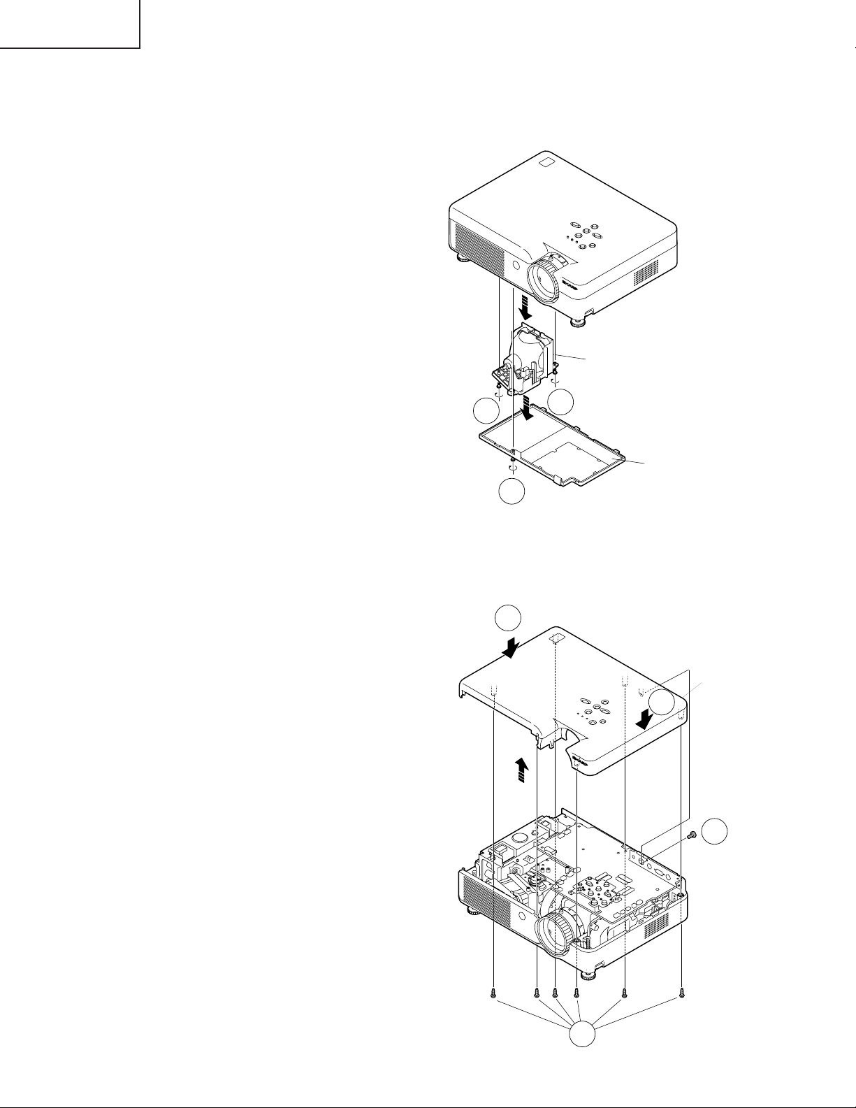
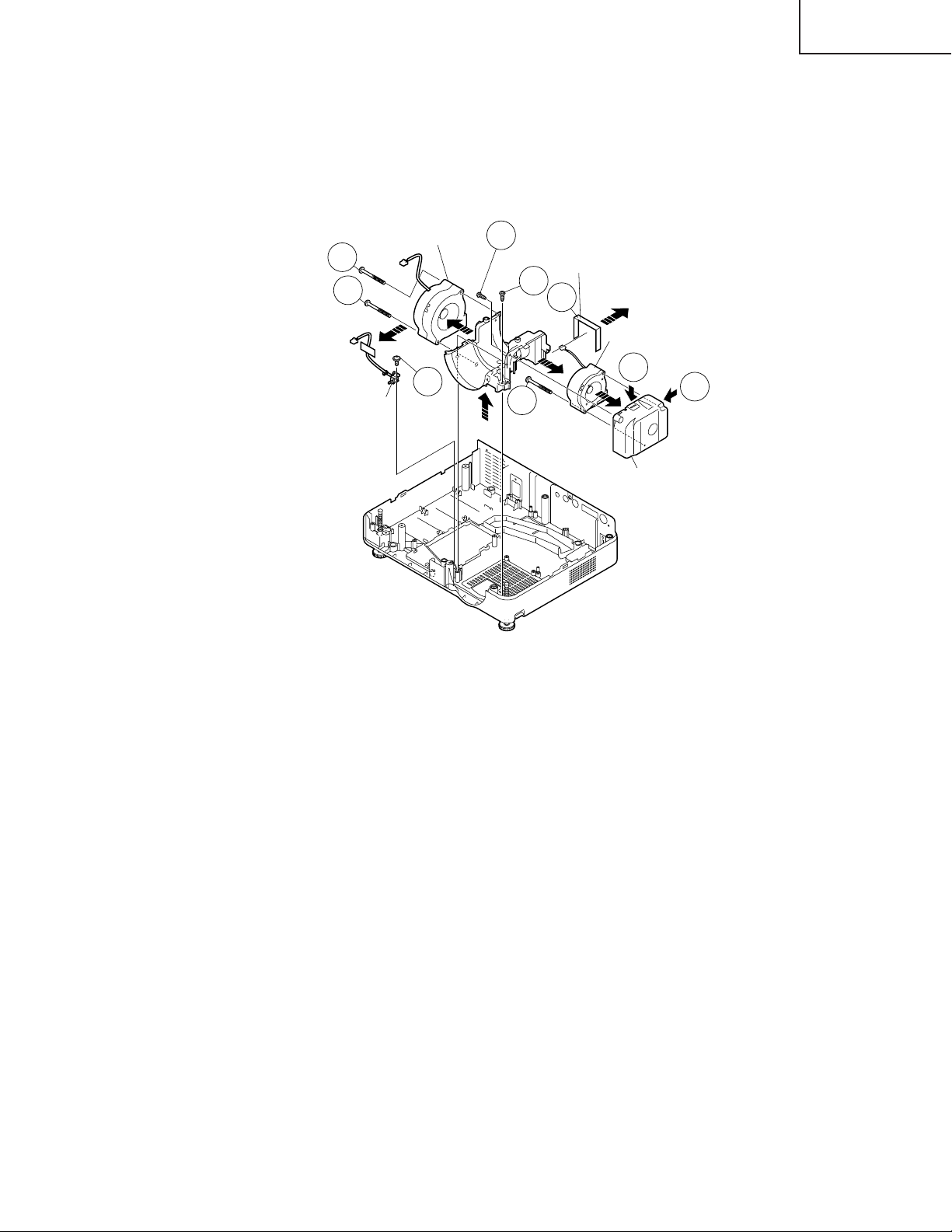
REMOVING OF MAJOR PARTS
1.Removing the lamp unit.
1-1. Loosen a screw and detach the lamp door.
1-2. Loosen the two screws. Hold the lamp unit by the handle and pull it in the direction of allow.
Lamp Unit
2.Removing the top body
2-1. Remove a screw from behind of the set.
2-2. Remove the six lock screws from bottom of the set.
2-3. Remove the two hooks and detach the top body.
1-2
1-2
Lamp Door
1-1
2-3
Top Body
2-3
16
2-1
2-2
Page 17
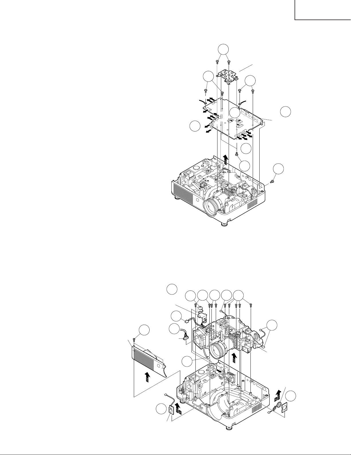
3.Removing the main PWB unit
3-1. Remove the seven screws.
3-2. Remove all the connectors from main PWB.
3-3. Detach the main PWB.
3-4. Remove the two screws and detach the operation
button unit.
PG-A10X
PG-A10X-SL
AN-A10T
3-1
Operation Button
3-2
3-1
[FC]
[FA]
[EA]
[LF]
[RC]
[FG]
[TF]
[BP]
[FD]
3-2
3-1
3-3
[GP]
[RP]
[TH]
[FB]
[FE]
[SP]
[TI]
MAIN PWB
3-2
3-4
3-1
4.Removing the exhaust cover, optical mechanism unit, R/C receiver PWB
and speaker
4-1. Remove the two screws and detach the lamp socket.
4-2. Detach the Power/Ballast holder cover.
4-3. Remove all the connectors from optical mechanism unit.
4-4. Remove the nine screws and take out of the optical mechanism unit and the exhaust cover.
4-5. Detach the R/C receiver PWB.
4-6. Detach the Speaker.
Exhaust
Cover
Power/Ballast
Holder Cover
4-4
4-2
4-3
4-1
Lamp
Socket
4-3
4-4
4-1
4-3
4-4
4-3
4-5
R/C Receiver PWB
Optical mechanism unit
4-3
Speaker
4-6
17
Page 18
PG-A10X
PG-A10X-SL
AN-A10T
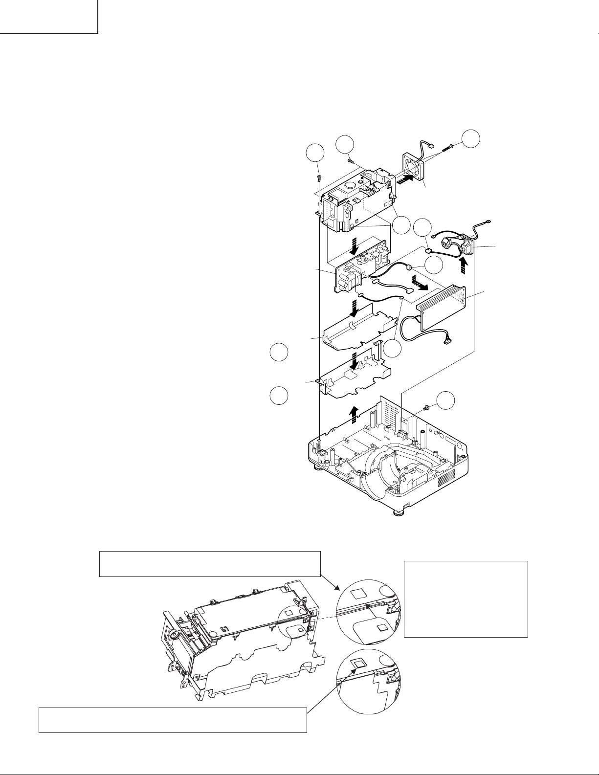
5.Removing the AC inlet, power/ballast unit and cooling fan
5-1. Remove a screw from behind of the set.
5-2. Remove a screw and take out of the power/ballast assembly.
5-3. Detach the bottom shield and shield cover.
5-4. Remove a connector and detach the AC inlet.
5-5. Remove the two hooks and take out of the ballast unit from power/ballast case. Remove the all connectors
from power PWB.
5-6. Remove the two screws and detach the power PWB.
5-7. Remove the two screws and cooling fan.
5-2
5-6
5-5
Cooling Fan
5-4
5-7
AC Inlet
Power PWB
Bottom Shield
5-3
Shield Cover
5-3
5-5
5-5
Ballast Unit
5-1
Note: When mounting the shield (bottom) for power supply/ballast (PSLDMA189WJFW) on the power supply/ballast
holder ass'y (CHLDZA135WJ01), make sure that it is inserted into the following place.
Be sure to insert the claw of the bottom shield into
the gap between the upper shield and holder.
After assembly, make sure that the claw of the bottom shield
is visible from the square hole on the upper shield.
18
* Never insert the claw be-
tween the insulating plate
and holder since the insulating distance to the ballast PWB becomes inadequate.
Page 19
PG-A10X
PG-A10X-SL
AN-A10T
6.Removing the intake duct assembly
6-1. Remove the two screws and take out of the intake duct assembly.
6-2. Remove a screw and detach the leaf switch.
6-3. Remove a screw and two hooks. Detach the the spacer B. Take out of the fan LCD R/G-intake duct B
assembly.
6-4. Remove a screw and detach the fan LCD R/G.
6-5. Remove the two screws and detach the fan LCD B.
6-5
6-5
Leaf Switch
Fan LCD B
6-2
6-3
Spacer B
6-1
6-3
Fan LCD R/G
6-3
6-3
6-4
Intake Duct B
19
Page 20
PG-A10X
PG-A10X-SL
AN-A10T
Resetting the TOTAL LAMP TIMER
● Resetting the total lamp timer
When replacing the lamp, reset the total lamp timer in the procedure below.
2
1
Connect the power cord.
• Plug the power cord into the AC socket
of the projector.
AC socket
Reset the lamp timer.
•
While simultaneously
and on the projector, press
and on the projector.
• “LAMP 0000H” is displayed, indicating
that the lamp timer is reset.
holding down
Power ON button
Volume
buttons
AUTO SYNC
button
■ The warning lights on the projector indicate problems inside the projector.
■ If a problem occurs, either the temperature warning indicator or the lamp replacement indicator will illumi-
nate red, and the power will turn off. After the power has been turned off, follow the proce-duresgiven
below.
Maintenance indicator
Temperature
warning
indicator
Lamp
replacement
indicator
Power
indicator
Normal Abnormal
Green on
when the
lamp is
Green on/
Red on
Off
Green
blinks
active.
Abnormal
Red on/
Power off
Red on
Red on/
Power off
Red blinks
Condition Problem Possible Solution
•
The internal
temperature is
abnormally high.
Time to change
the lamp
The lamp does
not illuminate.
The power
indicator blinks
in red when the
projector is on.
Blocked air intake
•
Cooling fan breakdown
•
Internal circuit failure
•
Clogged air intake
•
Remaining lamp life
becomes 5% or less.
•
Burnt-out lamp
•
Lamp circuit failure
•
The filter/lamp unit
cover is open.
■ Replacing the Air Filter
• This projector is equipped with air filters to ensure the optimal operating
condition of the projector.
• The air filters should be cleaned every
100 hours of use. Clean the filters more
often when the projector is used in a
dusty or smoky location.
• Ask your nearest Sharp Authorized Projector Dealer or Service Center to exchange the filter (PFILDA008WJZZ)
when it is no longer possible to clean.
Cleaning and Replacing
the Air Filter
1
Turn off the power and disconnect the power cord.
• Press on the projector or
on the remote control. Wait until the cooling fan stops.
Bottom view
Air filter
Power OFF button
Rear view
Air filter
(not removable)
Air filter
(not removable)
Power
OFF
button
4
Clean the air filter.
• Clean the dust off the air filter and cover
with a vacuum cleaner extension hose.
5
Replace the air filter.
• Place the air filter underneath the tabs
on the filter/lamp unit cover.
Info
• Make sure to reset the lamp timer only
when replacing the lamp. If you reset the
lamp timer and continue to use the same
lamp, this may cause the lamp to become
damaged or explode.
•
Relocate the projector to an area
with proper ventilation.
•
Take the projector to your nearest
Sharp Authorized Projector Dealer
or Service Center for repair.
•
Carefully replace the lamp.
•
Take the projector to your nearest
Sharp Authorized Projector Dealer
or Service Center for repair.
•
Please exercise care when
replacing the lamp.
•
Securely install the cover.
•
If the power indicator blinks even
when the filter/lamp unit cover is
securely installed, contact your
nearest Sharp Authorized Projector Dealer or Service Center for
advice.
2
Remove the filter/lamp unit
cover.
• Turn the projector over. Loosen the user
service screw (1) that secures the filter/lamp unit cover. Pressing the tab
(2), remove the filter/lamp unit cover
(3).
3
Remove the air filter.
• Pick the air filter up with your fingers and
lift it out of the filter/lamp unit cover.
6
Replace the filter/lamp unit
cover.
• Align the tab on the filter/lamp unit cover
(1) and place it while pressing the tab
3
1
User service screw
Tab
2
(2) to close it. Then tighten the user
service screw (3) to secure the filter/
lamp unit cover.
Note
• Be sure the filter/lamp unit cover is securely
installed. The pow er will not turn on unless
it is correctly installed.
• If dust or dir t has collected inside the rear
and bottom air filters (not removable), clean
the filter with a vacuum cleaner extension
hose.
Tab
1
2
3
User service screw
20
Page 21
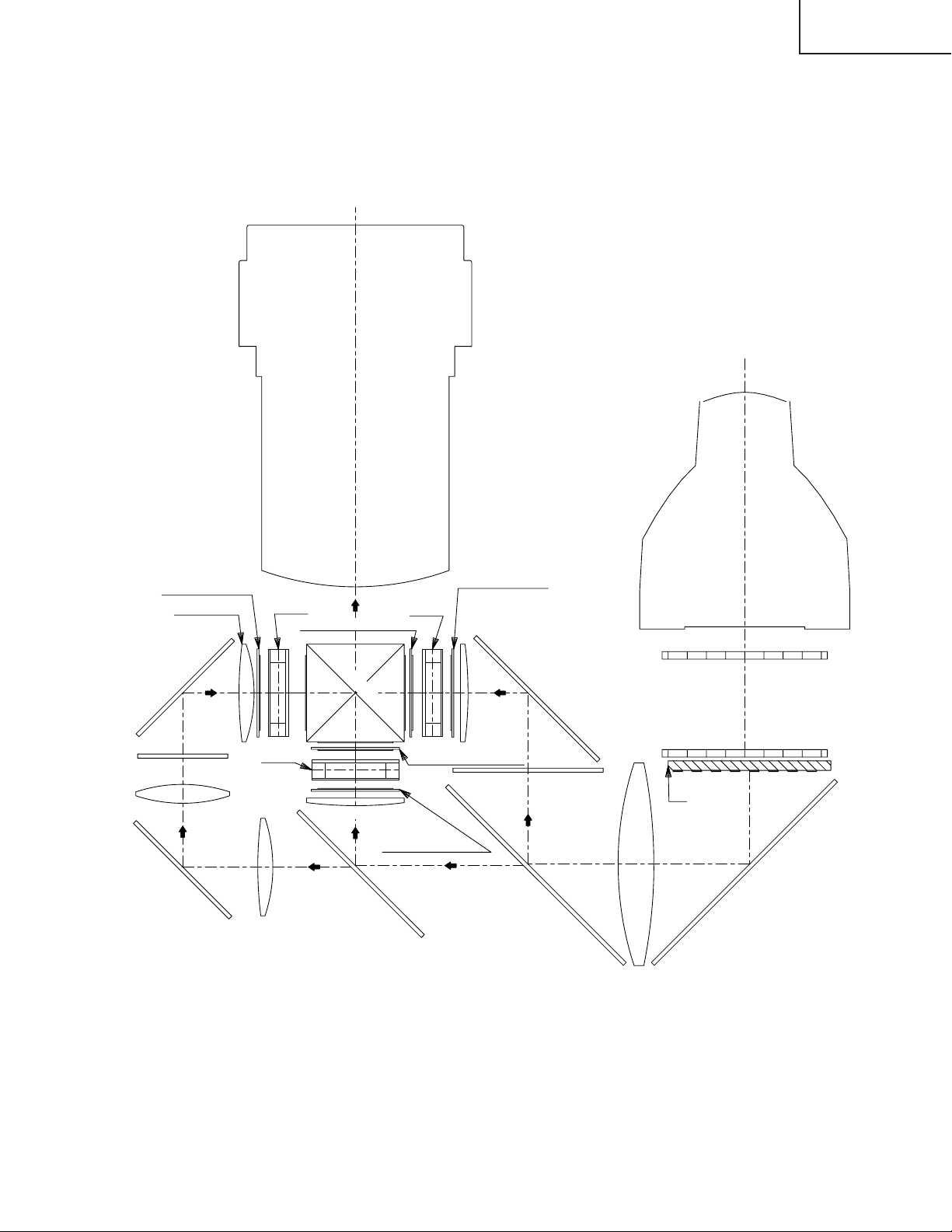
THE OPTICAL UNIT OUTLINE
Layout for proper setup of the optical components and parts (top view)
Projection lens
PG-A10X
PG-A10X-SL
AN-A10T
Input polarizer R
Relay lens 3
Mirror R 2
R dichroic filter
Relay lens 2
Mirror R 1
LCD(R)
LCD(G)
Relay lens 1
Output pre-polarizer B
Cross dichroic prizm
Condencing lens G
Green
Input polarizer G
Red
G reflector
Input polarizer B
LCD(B)
Output pre-polarizer G
Green/Red
Condencing lens B
UV reflector
Mirror B
Blue
B reflector
PBS
Condencing lens
LIGHT SOURCE
(LAMP)
Fly-eye lens(Input)
Fly-eye lens(Output)
Mirror R,G,B
21
Page 22
PG-A10X
PG-A10X-SL
AN-A10T
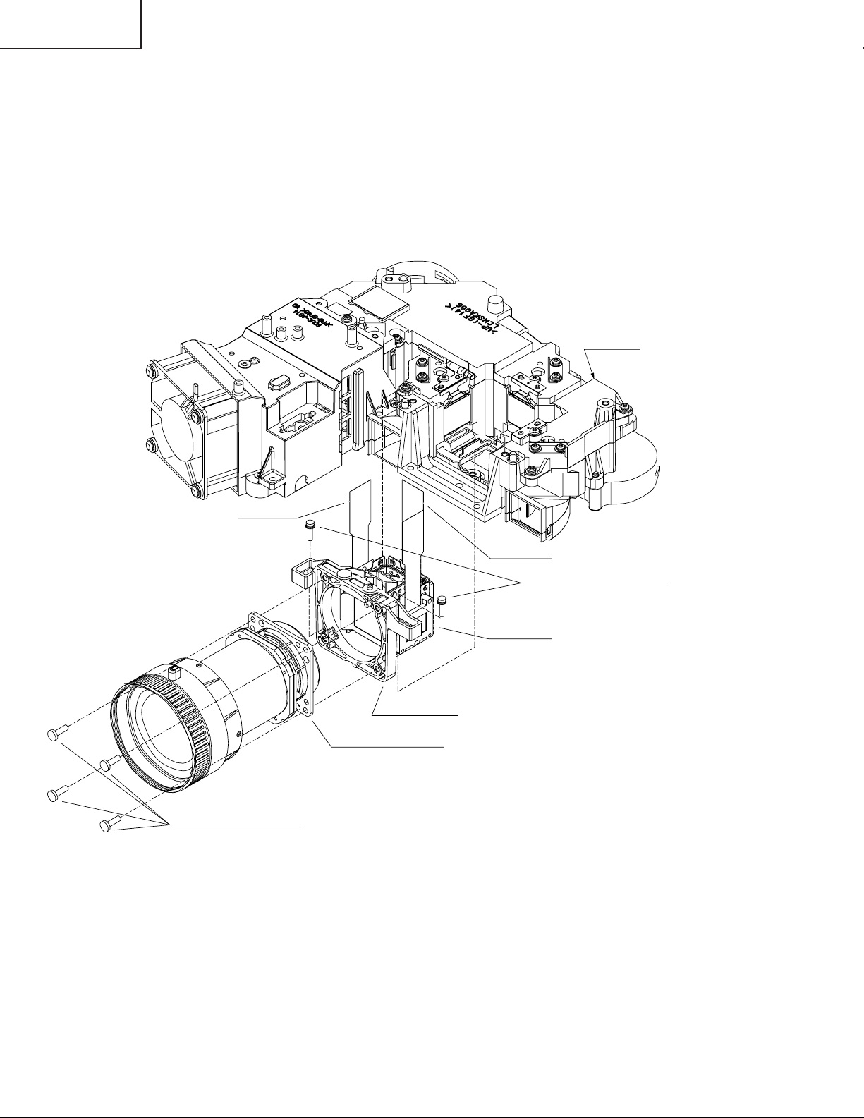
Replacing the prism holder unit
1. Remove the two lock screws, and take the prism holder unit and the projection lens assembly out of the optical
unit.
2. Remove the four lock screws, separate the prism holder unit and the projection lens assembly from each other.
3. Replace the prism holder unit with new one. Take the above steps 1 and 2 in reverse order.
Note: Even if just one of the LCD panels is defective, it is necessary to replace the entire prism holder unit. Do not
replace just the defective LCD panel only.
Optical unit
B-LCD panel
2Projection lens lock screws
G-LCD panel
1Prizm holder unit lock screws
R-LCD panel
Prizm holder unit
Projection lens assembly
22
Page 23

ELECTRICAL ADJUSTMENT
No. Adjusting point Adjusting conditions Adjusting procedure
PG-A10X
PG-A10X-SL
AN-A10T
1 EEPROM
initialization
2-1 R/G/B Bright-
ness adjustment
2-2 R/G/B Contrast
adjustment
1. Turn on the power (with the
lamp on) and warm up the
set for 15 minutes.
1. Select the following group
and subjects.
Group : AD
Subject : R-Bright
G-Bright
B-Bright
(Process GAMMA interlock)
2. Feed the XGA 16-step signal with an amplitude level
of 50% (0.35 Vp-p).
1. Select the following group
and subjects.
Group : AD
Subject : R-Contrast
G-Contrast
B-Contrast
(Process GAMMA interlock)
2. Feed the XGA white signal
with an amplitude level of
96% (0.67 Vp-p).
» Make the following settings.
Press S2002 to call the process mode and execute
"SS2" on SS menu.
1.Watching the screen, adjust the R-, G- and B-Bright
settings so that the second tone (3% level step) on
the black side should have some pixel dropouts and
the bright color zone should become just about a half.
1.Watching the screen, adjust the R-, G- and B-Contrast settings so that because of some pixel dropouts, the bright color zone should become just about
a half.
3 DTV Brightness/
Contrast adjustment
4 DVD Brightness/
Contrast adjustment
1. Feed a 480P component
10-step signal with 100%
amplitude.
2. Select the following group
and subjects.
Group : DTV
Subject : Bright
Contrast
(Process GAMMA interlock)
1. Feed a 480PI component
10-step signal with 100%
amplitude.
2. Select the following group
and subjects.
Group : DVD
Subject : Bright
Contrast
(Process GAMMA interlock)
1. Check the setting value.
Contrast (White Level): 7
Bright (Black Level): 6
1. Check the setting value.
Contrast (White Level): 6
Bright (Black Level): 8
23
Page 24
PG-A10X
PG-A10X-SL
AN-A10T
No. Adjusting point Adjusting conditions Adjusting procedure
5 Video Bright-
ness/Contrast
adjustment
6 PSIG adjust-
ment
1. Feed an NTSC composite
video 10-step signal (no
setup) with 100% amplitude.
2. Select the following group
and subjects.
Group : DVD
Subject : Bright
Contrast
(Process GAMMA interlock)
1. Select the following group
and subjects.
Group : OUTPUT2
Subject : PSIG-H
PSIG-L
2. Check the fixed value.
PSIG-H: 64
PSIG-L: 146
1. Check the setting value.
Contrast (White Level): 5
Bright (Black Level): 8
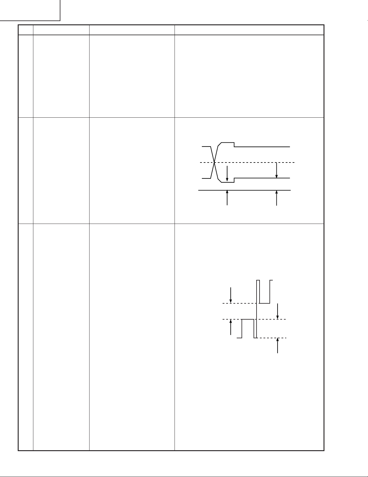
1. Feed the XGA signal and adjust to make the following PSIG waveform. (TP1 101, TP1201 and TP1301)
PSIG
2.5V DC
Adjust with PSIG-H
5.6V DC
Adjust with PSIG-L
GND
7 R/G/B Black
Level Signal
Amplitude
adjustment
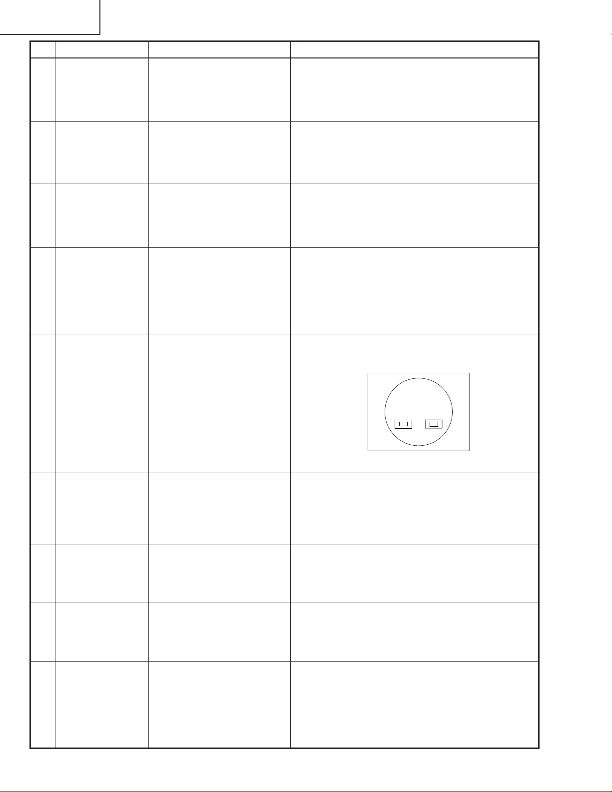
1. Select the following group
and subjects.
Group : OUTPUT1
Subject :
On Green adjustment
G1-BLK
G1-GAIN
On Red Adjustment
R1-BLK
R1-GAIN
On Blue Adjustment
B1-BLK
B1-GAIN
2. Make sure the process adjustment color bags appear
onscreen.
3. Connect a synchroscope to
P1301-2P for the G setting.
4. Connect the synchroscope
to P1301-1P and P13013P for the R and B settings,
respectively .
1. Select G1-GAIN. Using the set's control switch or
the remote controller's button, adjust the signal amplitude to 4.05 Vp-p ± 0.05 V.
2. Now select G1-BLK. Using the set's control switch
or the remote controller's button, adjust the whiteto-white level to 1.70 Vp-p ± 0.05 V.
3. Do the same for the R and B settings.
White-to-White
Amplitude
24
Page 25

No. Adjusting point Adjusting conditions Adjusting procedure
PG-A10X
PG-A10X-SL
AN-A10T
8 RGB
countervoltage
adjustment
9 RGB white
balance adjustment
10 sRGB adjust-
ment
1. Feed the countervoltage
adjustment signal. (XGA)
2. Select the following group
and subjects.
Group : OUTPUT3
Subject : RC (R)
GC (G)
BC (B)
1. Feed the RGB 50% gray
signal. (XGA)
2. Select the following group
and subjects.
Group : OUTPUT1
Subject : R1-BLK(R)
B1-BLK(B)
1. Feed the RGB 50% gray
signal. (XGA)
2. Select the following group
and subjects.
Group : OUTPUT1
Subject : S-R1-BLK
S-R1-GAIN
S-G1-BLK
S-G1-GAIN
S-B1-BLK
S-B1-GAIN
1.Using the set's control switch or the remote controller’s button, adjust the setting so that the flickering
be minimum.
2.Adjust the setting so that the image comes to the
center of the screen.
1.Adjust the R1-BLK and B1-BLK settings to have the
chromacity of x = 285 ± 5 and y = 323 ± 5. (8500K)
1.Adjust the S-R1-BLK and S-B1-BLK settings to have
the chromacity of x = 313 ± 5 and y = 344 ± 5.
(6500K)
11 Automatic color
irregularity
correction
12 Video Tint
adjustment
13 Video Color
saturation
adjustment
14 DTV Tint adjust-
ment
1. Apply the automatic color
correction using the automatic color irregularity correction system.
1. Select the following group
and subject.
Group : VIDEO
Subject : N-Tint
P-Tint
S-Tint
1. Select the following group
and subject.
Group : VIDEO
Subject : N-Color
P-Color
S-Color
1. Select the following group
and subject.
Group : DTV
Subject : Tint
1.Make sure that no remarkable uneven color remains
on the screen.
1. Check the fixed value.
N-Tint : 8
P-Tint : 8
S-Tint : 8
1. Check the fixed value.
N-Color : 10
P-Color : 10
S-Color : 10
1. Check the fixed value.
Tint : 8
25
Page 26
PG-A10X
PG-A10X-SL
AN-A10T
No. Adjusting point Adjusting conditions Adjusting procedure
15 DTV Color
saturation
adjustment
16 DVD Tint adjust-
ment
17 DVD Color
saturation
adjustment
18 Sample hold
pulse phase
checking
19 RGB tone
reproduction
adjustment
1. Select the following group
and subject.
Group : DTV
Subject : Color
1. Select the following group
and subject.
Group : DVD
Subject : Tint
1. Select the following group
and subject.
Group : DVD
Subject : Color
1. Feed the XGA 75-Hz black
signal.
2. Select the following group
and subjects.
Group : OUTPUT3
Subject : GCK-PHASE
1. Feed the SMPTE pattern
signal.
1. Check the fixed value.
Color : 13
1. Check the fixed value.
Tint : 8
1. Check the fixed value.
Color : 10
1. Check the fixed value.
Fixed Value : 8
1. Make sure the 100% and 95% white as well as the
0% and 5% black gradations are visible.
20 White balance
checking
21 Color-related
performance
checking
22 Video-related
performance
checking
23 RGB perform-
ance checking
1. Use the adjustment conditions in the item 9 for RGB
input and item 10 for sRGB
input.
1. Feed the color bar signal. 1.Select L1 of the process mode. Operation check of
1. Feed the monoscope pattern signal.
1. Feed the RGB signal. 1.Select L4 of the process mode. Operation check of
Check that there is no deviation of white balance with
the monitor.
Color and Tint.
1.Select L2 of the process mode. Operation check of
Picture, Bright and Sharpness.
Picture, Bright,Red, Blue, Clock, Phase, H-POS and
V-POS.
26
Page 27
No. Adjusting point Adjusting conditions Adjusting procedure
PG-A10X
PG-A10X-SL
AN-A10T
24 Off-timer per-
formance
performance
checking
26 Auto sync
performance
checking
27 Delivery set-
tings
1. Heat the thermistor with a
hair dryer.
1. Feed the phase check pattern signal.
1. Select OFF from the process mode.
Make sure the off-timer starts with 5 minutes
onscreen and count one minute in one second.
And then indication is 0 minute, the power supply
of the set is cut off.
.
1.Make sure that the temperature is indicated.25 Thermistor
1.In the VGA, SVGA and XGA modes, make sure the
Clock, Phase, H-Pos and V-Pos settings can be automatically adjusted.
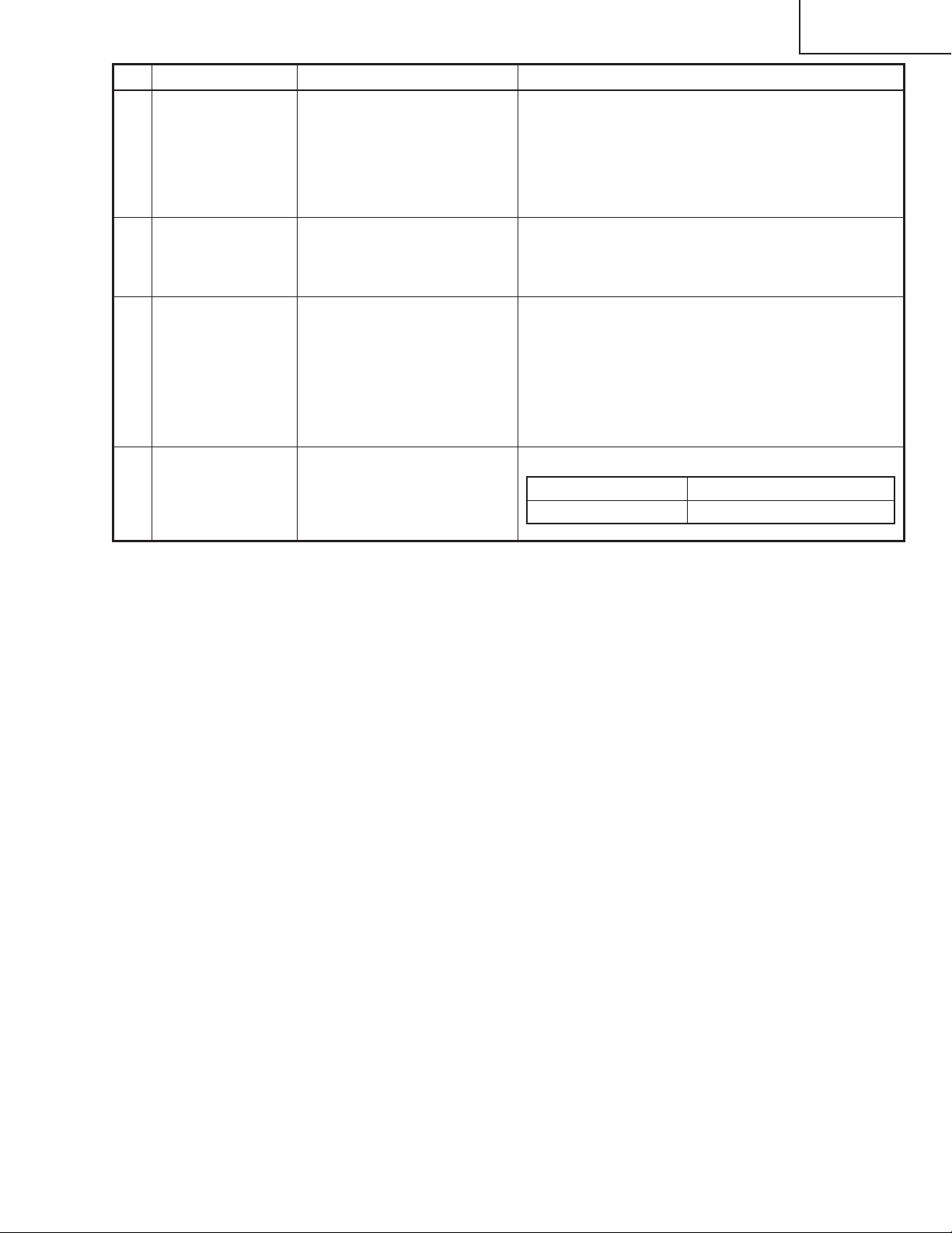
1.Make the following settings.
Process adjustment Remote control adjustment
S3 Factory setting at 3
27
Page 28
PG-A10X
PG-A10X-SL
AN-A10T
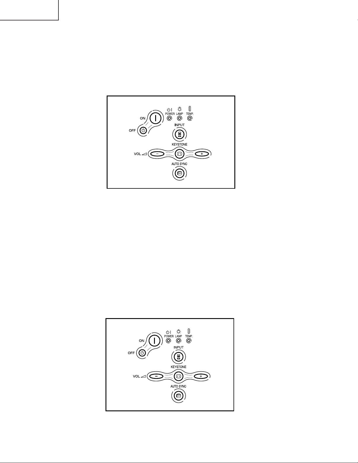
1.Calling and quitting the process mode with the control keys on this model.
1-1. Calling and quitting
With no menu onscreen, press the "UP", "UP", "DOWN", "DOWN", "RIGHT", "LEFT" and "ENTER" keys, in this
order, on the remote controller (Type A10, or C50/45 and P25/20 series remote controllers).
1-2. Others
Press the S2002 process key (toggle) on the main PWB to call and quit the process menu.
2.Resetting the lamp timer for this model
Power On
Power Off
Keystone
Volume Down
Input Select
Volume Up
Auto Sync
2-1. Resetting procedure
While holding down the Vol+ and AUTOSYNC keys, press the POWER ON and Vol- keys. The "LAMP 000H"
indicator appears for 60 seconds after the power is turned on.
3.Forced disabling of the Anti-Seft of this model
3-1. Disabling procedure
With Anti-Seft input window onscreen, press the "MENU", "ENTER", "ENTER", "MENU", "UNDO", "UNDO" and
"MENU" keys, in this order, on the remote controller.
4.Forced disabling of the password of this model
1-1. Disabling procedure
In whatever state, press the "ON", "+", "–", "ON", "+", "–" and "INPUT" keys in this order.
Power On
Power Off
Keystone
Volume Down
Input Select
Volume Up
Auto Sync
28
Page 29
Process menu1
PG-A10X
PG-A10X-SL
AN-A10T
Adjustment Process Menu
First layer DTV Pedestal
DVD VERSION
VIDEO SS
AD TEMP
OUTPUT1 PATTERN
OUTPUT2 LAMP
OUTPUT3 LINE
VIDEO1 EXIT
second layer Initial Value
DTV Contrast 4
Tint 5
Color 13
Sharpness 1
CTI-Level 1
LTI-Level 0
CB-Offset 7
CR-Offset 7
Bright 15
B-DRIVE 41
R-DRIVE 41
EXIT
DVD Contrast 3
Tint 5
Color 10
Sharpness 1
CTI-Level 1
LTI-Level 0
CB-Offset 7
CR-Offset 7
Bright 16
B-DRIVE 41
R-DRIVE 41
EXIT
VIDEO Contrast 2
N-Tint 5
P-Tint 5
S-Tint 5
N-Color 10
P-Color 10
S-Color 10
Sharpness 1
CTI-Level 1
LTI-Level 0
CB-Offset 7
VIDEO CR-Offset 7
Bright 16
B-DRIVE 41
R-DRIVE 41
EXIT
AD R-Bright 67
G-Bright 67
B-Bright 67
R-Contrast 167
G-Contrast 167
B-Contrast 167
EXIT
OUTPUT1 R1-BLK 120
R1-GAIN 152
G1-BLK 140
G1-GAIN 152
B1-BLK 160
B1-GAIN 152
S-R1-BLK 120
S-R1-GAIN 152
S-G1-BLK 140
S-G1-GAIN 152
S-B1-BLK 160
S-B1-GAIN 152
EXIT
OUTPUT2 PSIG-H 64
PSIG-L 146
EXIT
OUTPUT3 RC 135
GC 135
BC 135
GCK-PHASE 8
CC 1
EXIT
VIDEO1 N-Contrast 14
P-Contrast 14
S-Contrast 15
Color 17
NT3.58 Delay 1
NT4.43 Delay 1
PAL Delay 1
SECAM Delay 3
EXIT
Pedestal R-Bright -10
G-Bright -10
B-Bright -10
29
Page 30
PG-A10X
PG-A10X-SL
AN-A10T
Process menu2
Pedestal R-Contrast +10
G-Contrast +10
B-Contrast +10
EXIT
VERSION Build
Boot Code
Config
Rom Code
GUI
EXIT
SS SS2
SS3 EU
SS4 US
SS5 JPN
SS6 CHIN
EXIT
TEMP Temp1 Parameter of sensor 1
Temp2 Parameter of sensor 2
Temp3 No Use
Temp4 No Use
EXIT
P ATTERN Cross Hatch
Color Bar
EXIT
LAMP Current Time Current time of use
History1 One earlier
History2 Two earlier
History3 Three earlie
History4 Four earlier
TOTAL TIME Total operating hours
EXIT
LINE OFF
LED CHECK
EXIT
30
Page 31

YES
YES
NO
Checking the basic
performance
Is the POWER LED on or
flickering in red or green?
Go to "Checking the
power unit"
Go to "Checking the lamp
light-up"
NO
Is the set turned on by the
set’s or remote controller’s
power key?
Go to "Checking the
microcomputer
peripherals".
NO
Go to "Checking the RGB
sync.".
Go to "Checking the RGB
signal"
Go to "Checking the
video system".
End
NO
Is the cooling fan
running? Is the lamp on?
Is the user menu
displayed?
YES
YES
PG-A10X
PG-A10X-SL
AN-A10T
TROUBLE SHOOTING TABLE
31
Page 32

PG-A10X
PG-A10X-SL
AN-A10T
Checking the power unit
Are the connectors CN701,
CN702 and CN751
inserted completely?
YES
Is the bimetal switch off?
YES
Is there AC voltage (100240V) applied across
C701?
YES
Disconnect the CN751
connector. Is there 6V
output at pins (3) and (4)?
YES
NO
Insert the connectors
CN701, CN702 and
CN751 tightly?
NO
Replace the bimetal
NO
Replace F701.
NO
Check Q702 for damage.
Replace as required.
Check the MAIN PWB for
short-circuit.
32
Page 33

YES
YES
YES
YES
YES
NO
Checking the
microcomputer
peripherals
Is a voltage of about 3.3V
DC applied to pins (3) and
(5) of IC1703?
Check IC1703 and its
peripheral circuits, or IC1702
and its peripheral circuits.
Is the lamp access lid
open? Is the P2006 (LF)
tight in the socket?
Check IC2002 and its
peripheral circuits.
Check IC8202, IC8203,
IC2601 and their
peripheral circuits.
Check IC1704 and its
peripheral circuits.
NO
Is about DC 2.5V applied
between pins (5) and (8) of
IC1704?
NO
Check IC8009 and its
peripheral circuits.
NO
See if the fan is running as
specified. Or check IC8003
and its peripheral circuits.
NO
Is about DC 2.5V applied
between pins (4) and (3) of
IC8009?
Is there about DC3V
applied at pin (21) of
IC2002? Do the D0 thru D7
signals appear as pulse
signals on the oscilloscope
screen?
Fully close the lamp access
lid. Or insert the P2006 (LF)
tightly in the socket.
YES
Check IC8010, IC8011 and
their peripheral circuits.
NO
Is there 133-MHz clock
output at pin (6) of IC8010?
Is there 75-MHz clock
output at pin (6) of IC8011?
PG-A10X
PG-A10X-SL
AN-A10T
33
Page 34

PG-A10X
PG-A10X-SL
AN-A10T
Checking the lamp
light-up
Is the lamp socket
disconnected?
NO
Are DC350-400V voltages
applied between the pins
of CN703?
YES
Are the CN751 and
CN752 harnesses tight in
position in the power unit
and ballast unit as well?
Are these harnesses free
of damage?
YES
Are there 3V (High level)
and 1V applied at pins (1)
and (13), respectively, of
CN751 in the power unit?
YES
YES
Reconnect the lamp
socket tightly.
NO
Go to "Checking the
power unit".
NO
Reconnect the CN751
and CN752 harnesses
tight enough. Or replace
these harnesses.
NO
Go to "Checking the
microcomputer
peripherals".
Replace the ballast unit.
Checking the RGB
sync
Are theire signal inputted
into pins (2)
of IC5002, IC5015?
YES
Are theire signal inputted
into pins (30),
(31) of IC6004?
NO
Check RGB terminal and
its peripheral circuits
NO
Check IC6001 and its
peripheral cuicuits.
34
Page 35

YES
YES
NO
YES
YES
NO
YES
YES
NO
Checking the RGB signal
Are their RIN2-RIN9,
GIN2-GIN9, BIN2-BIN9
signals inputted into
IC2601 ?
Check IC8003 and its
peripheral circuits.
Are the RGB signals
outputted from
pin (9), (7), (4) of IC3104?
gradation signals?
Check IC3104 and its
peripheral circuits.
NO
Are their signals inputted
into pins(51)-(55) (58)-(62)
of IC1101, IC1102,IC1201,
IC1202, IC1301, IC1302?
Check IC2601 and its
peripheral circuits.
NO
Are the signals inputted
into the pins (31) of
SC1101, SC1201 and
SC1301?
Check IC1103, and its
peripheral circuits.
Are the signals inputted
into the pins (1) of
SC1101, SC1201 and
SC1301?
Check IC1101, IC1201,
IC1301, and their
peripheral circuits.
NO
Check the connection
of LCD panels.
And when video signal and
OSD are also not
disaplaied, replace the
LCD panels .
Are their signals inputted
into pins (3)-(14) of
SC1101, SC1201 and
SC1301?
Check IC1101, IC1102,
IC1201, IC1202, IC1301,
IC1302 and their peripheral
circuits.
PG-A10X
PG-A10X-SL
AN-A10T
35
Page 36

PG-A10X
PG-A10X-SL
AN-A10T
No colour or unusual
tone(NTSC, PAL)
Are there RGB outputs at
pins (23)(R-Y), (22)(B-Y) of
IC3105?
YES
Check C3126, C3124.
No or unusual Y signal
Are there RGB outputs at
pins (21)(Y) of IC3105?
YES
Check C3121.
Checking IC3102 (RGB
signal output circuit)
NO
Check IC3105 and
peripheral circuits.
NO
Check IC3506 and
peripheral circuits.
Are there signal outputs at
pins (66)(R-Y), (68)(B-Y),
(69)(Y) of IC3102 ?
YES
Are there RGB outputs
waveforms at pins(35),
(37), (39) of IC3102 ?
YES
Are there output
waveforms at the emitters
of Q3110, Q3111 and
Q3112?
NO
Go to "No colour or unusual
tone", "No Y signal" or "Out
of sync"
NO
Check the data transfer and
other performance at pins
(55) and (56) of IC3102.
NO
Check Q3110 thru Q3112
and their peripheral circuits.
36
Page 37

NO
YES
NO
NO
NO
YES
NO
NO
YES
NO
NO
NO
Checking the S-video
system
Is the specified voltage EA
connectors?
Check power circuit and its
parts.
Is the lamp on ?
Go to "Lamp light-up".
YES
Is the video signal inputted
into the pin(43), (44) of
IC3105?
Check the video terminal
and its peripheral circuits.
YES
Go to "Checking IC3102"
Checking the video
system
Is the specified voltage EA
connectors?
Check power circuit and its
parts.
Is the lamp on ?
Go to "Lamp light-up".
YES
Is the video signal inputted
into the pin(7) of IC3506?
Check the video terminal
and its peripheral circuits.
YES
Check IC3105 and its
prepheral circuits.
Check IC1103, and its
peripheral circuits.
Is the signal inputted into
the pin(39), (41) of
IC3105?
Check Q3501, Q3502 and
their peripheral circuits.
YES
Is the video signal
outputted from the pin
pin(25), (27) of IC3506?
Check IC3506 and its
peripheral circuits.
PG-A10X
PG-A10X-SL
AN-A10T
37
Page 38

PG-A10X
PG-A10X-SL
AN-A10T
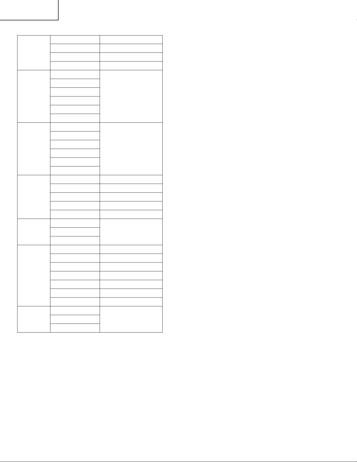
Technische Daten
Produkttyp LCD-Projektor
Modell PG-A10X / PG-A10X-SL
Videosystem NTSC3.58/NTSC4.43/PAL/PAL-M/PAL-N/PAL-60/SECAM/
DTV480I/DTV480P/DTV540P/DTV580I/DTV580P/DTV720P/DTV1035I/DTV1080I
Anzeigeverfahren LCD-Panel × 3,optische RGB-Verschlussmethode
LCD-Panel Panel-Größe:0,79tum(20,0 mm)(12 [H ] x 16 [B ] mm))
Anzahl der Bildpunkte:786.432 Bildpunkte (1.024 [H ] x 768 [V ])
Standard-Objektiv 1 –1,2 × Zoom-Objektiv,F1,9 –2,2,f =26 –31 mm
Projektionslampe Wechselstromlampe SHP 165 W-Lampe
Komponenten-Eingangssignale 15-Pin-Mini-D-Sub-Anschluss
(INPUT 1) Y:1,0 Vp-p,negatives Sync.,75 Ω terminiert
PB:0,7 Vp-p,75 Ω terminiert
PR:0,7 Vp-p,75 Ω terminiert
Horizontale Auflösung 700 Fernsehzeilen (DTV720P)
Computer-RGB-Eingangssignal 15-Pin-Mini-D-Sub-Anschluss
(INPUT 1) RGB getrennt/Sync.auf Grün-Typ analoger Eingang:0-0,7 Vp-p,positiv,75 Ω terminiert
HORIZONTALES SYNC.-SIGNAL:TTL-Pegel (positiv/negativ)
VERTIKALES SYNC.-SIGNAL:Wie oben
S-Videoeingangssignal 4-pin-Mini-DIN-Anschluss
(INPUT 2) Y (Luminanzsignal):1,0 Vp-p,negatives Sync.,75 Ω terminiert
C (Chrominanzsignal):Sto ß 0,286 Vp-p,75 Ω terminiert
xVideoeingangssignal RCA-Anschluss:VIDEO,Verbund-Video,1,0 Vp-p,negatives Sync.,75 Ω terminiert
(INPUT 3)
Computer-Steuerungssignal (RS-232C) 9-Pin-Mini-DIN-Stecker
Pixeltakt 12-108 MHz
Vertikale Frequenz 43-85 Hz*
Horizontale Frequenz 15-70 kHz
Audioeingangssignal ø 3,5 mm-Minibuchse:AUDIO,0,5 Vrms,mehr als 47 kΩ (Stereo)
Audioausgang 1,0 W (Mono)
Lautsprechersystem 2,8 cm rund × 1
Nennspannung 100-240 V Wechselstromspannung
Eingangsstrom 2,4 A
Nennfrequenz 50/60 Hz
Leistungsaufnahme 240 W (Standard-Modus)/190 W (Eco-Modus)bei AC 100 V
226 W (Standard-Modus)/182 W (Eco-Modus)bei AC 240 V
Leistungsaufnahme 5 W (bei AC 100 V)-8 W (bei AC 240 V)
(Bereitschaft) 900 BTU/Stunde (Standard-Modus)/710 BTU/stunde (Eco-Modues)bei AC 100 V
Wärmeableitung 850 BTU/Stunde (Standard-Modus)/680 BTU/stunde (Eco-Modues)bei AC 240 V
41 °F bis 95 °F (+5 °C bis +35 °C)
Betriebstemperatur – 4 °F bis 140 °F (–20 °C bis +60 °C)
Lagertemperatur Plastik
Gehäuse 38 kHz
I/R-Trägerfrequenz 11 45/64" × 3 13/64" × 9 1/32" (297 (B) × 81 (H) × 229 (T)mm)(nur Hauptgerät)
Abmessungen (ca.) 11 45/64" × 3 33/64" × 9 1/32" (297 (B) × 89 (H) × 229 (T)mm)(einschließlich Einstellfüße und
Projektionsteile)
Gewicht (ca.) 6,4 lbs.(2,9 kg)
Mitgeliefertes Zubehör Fernbedienung, zwei R6-Batterien, Netzkabel für USA,Kanada usw. (6',1,8 m), Netzkabel für Europa,
außer Großbritannien (6',1,8 m), Netzkabel für Großbritannien,Hongkong und Singapur (6', 1,8 m),
Netzkabel für Australien, Neuseeland und Ozeanien (6', 1,8 m), RGB-Kabel (9'10", 3,0 m), DIN-D-Sub
RS-232C-Adapter (5 57/64", 15 cm), Tragetasche, Objektivkappe (befestigt), zusätzlicher Luftfilter,
Projektorhandbuch-und technische Referenz-CD-ROM, “QUICK GUIDE (Schnellanleitung)”-Aufkleber,
Bedienungsanleitung
Ersatzteile Lampeneinheit (Lampen-/Gehäusemodul)(BQC-PGA10X//1), Fernbedienung (RRMCGA138WJSA),
zwei R 6-Batterien (“AA”,UM/SUM-3,HP-7 oder entsprechend), Netzkabel für USA,Kanada
usw.(QACCDA016WJPZ), Netzkabel für Europa, außer Großbritannien (QACCV A006WJPZ), Netzkabel
für Großbritannien, Hongkong und Singapur (QACCBA015WJPZ), Netzkabel für Australien,Neuseeland
und Ozeanien (QACCLA005WJPZ), RGB-Kable (QCNWGA012WJPZ),DIN-D- Sub RS-232C-Adapter
(QCNWGA015WJPZ),Tragetasche (GCASNA006WJSA),Objektivkappe (CCAPHA007WJ01), Luftfilter
(PFILDA008WJZZ), Projektorhandbuch-und-technische Referenz-CD-ROM (UDSKAA022WJN1),
“QUICK GUIDE (Schnellanleitung)”-Aufkleber (TLABZA191WJZZ), Bedienungsanleitung (TiNSA505WJN1)
Dieser SHARP-Projektor verwendet eine LCD (Liquid Crystal Display)Anzeige. Diese hochmoderne Anzeige enth ä lt 786.432 Pixel (x RGB)
TFTs (Thin Film Transistors). Wie bei allen technologisch
fortschrittlichen,elektronischen Geräten,z.B.Großbild-Fernsehern,
Videosystemen bzw.V ideokameras,sind bestimmte Toleranzgrenzen für
die Funktionen gegeben.
Änderungen der technischen Daten ohne vorherige Ankündigung vorbehalten.
Dieses Ger ä t hat einige inaktive,innerhalb akzeptierter T oleranzgrenzen
liegende Bildpunkte,die als leuchtende oder als nicht aktive Punkte auf
der Bildwand wiedergegeben werden.Dies hat keinen Einfluss auf die
Bildqualit ä t oder die Lebensdauer des Ger ä tes.
38
Page 39

HINWEISE FÜR DAS
5
5
WARTUNGSPERSONAL
234567890123456789012345678901212345678901234
ACHTUNG: UV-STRAHLUNG
234567890123456789012345678901212345678901234
Die Beleuchtungsquelle des LCD-Projektors, eine
UHP-Lampe, emittiert eine geringe Menge
UV-Strahlung.
DIREKTE BESTRAHLUNG AUF AUGEN
UND HAUT MUSS VERMIEDEN WERDEN.
Zur Gewährleistung der Sicherheit muß folgendes
beachtet werden:
1. Bei Arbeiten am Projektor bei eingeschalteter
Lampe und abgenommenem oberen Gehäuse
muß unbedingt eine Sonnenbrille getragen
werden.
PG-A10X
PG-A10X-SL
AN-A10T
Auswechseln der Lampe
Hinweis:
Da die Lampe während des Betriebs sehr heiß wird,
sollte die Lampe erst ausgewechselt werden, nachdem
das Gerät mindestens eine Stunde ausgeschaltet war,
damit die Lampe ausreichend abkühlen kann.
Beim Installieren der neuen Lampe muß darauf
geachtet werden, die Lampe selbst (Glaskolben)
nicht zu berühren. Vielmehr muß die Lampe am
Reflektor 2 gehalten werden.
[Es darf nur ein Original-Ersatzteil verwendet
werden.]
Lampe
1
Reflektor
2
2. Die Lampe darf nicht außerhalb des
Lampengehäuses eingeschaltet werden.
3. Betrieb für länger als 2 Stunden bei
abgenommenem Gehäuse ist nicht zulässig.
Zur Beachtung bei UV-Strahlung
und Mitteldruck-Lampen
1. Vor dem Auswechseln der Lampe muß der
Netzstecker gezogen werden.
2. Vor Durchführung von Wartungsarbeiten muß das
Gerät eine Stunde abkühlen.
3. Die Lampe darf nur gegen eine der gleichen Art
ausgewechselt werden. Typ BQC-PGA10X//1,
bemessen für 100 V/200 W.
4. Die Lampe gibt eine geringe UV-Strahlung ab, daher
muß direkter Augenkontakt vermieden werden.
5. Die Mitteldruck-Lampe weist ein Explosionsrisiko auf.
Daher müssen die nachstehenden
Installationsanweisungen beachtet werden, und die
Lampe muß vorsichtig behandelt werden.
GEFAHR! — Niemals die Spannungsversorgung
einschalten, ohne daß eine Lampe vorhanden ist,
um elektrische Schläge und Schäden am Gerät zu
vermeiden, da der Stabilisator anfangs hohe
Spannungen erzeugt.
Da eine geringe Menge UV-Strahlung an der Öffnung
zwischen den Lüftern austritt, wird empfohlen, während der Wartungsarbeiten die Abdeckkappe des Zusatzobjektivs an dieser Öffnung anzubringen, um
Augen und Haut vor den UV-Strahlen zu schützen.
39
Page 40

PG-A10X
PG-A10X-SL
AN-A10T
Vorsichtsmaßregeln für bleifreien Lötzinn
1 Verwendung von bleifreiem Lötzinn
Bei den Platinen für Haupt und Fernbedienungsempfänger dieses Modells wird bleifreies Lot verwendet. Das
Symbol LF kennzeichnet bleifreies Lot und findet sich an den Platinen und in den Wartungshandbüchern. Der
Buchstabe hinter LF bezieht sich auf die Art des bleifreien Lots.
Beispiel:
L Fa
Zeigt bleifreien Lötzinn aus Zinn, Silber und Kupfer an.
2 Bei Reparatur der mit bleifreiem Lötzinn gelöteten Platine immer bleifreien Lötzinn verwenden. Reparatur mit
herkömmlichem Lötzinn kann zu Schäden oder Unfällen aufgrund von Rissen führen.
Da der Schmelzpunkt bleifreien Lvtzinns (Sn-Ag-Cu) um 40°C höher als der von Bleidraht-Lötzinn ist, empfehlen
wir die Verwendung einer speziellen Lötspitze. Wenn Fragen über den Beschaf fung leitfreien Lötzinns oder spezieller
Lötspitzen bestehen, wenden Sie sich an unsere Kundendienstvertretung in Ihrem Gebiet.
3 Löten
Da der Schmelzpunkt bleifreien Lötzinns (Sn-Ag-Cu) etwa 220°C beträgt, was um 40°C höher als der von bleihaltigem
Lötzinn ist, und außerdem schlechte Löt-Benetzbarkeit aufweist, kann es erforderlich werden, die Lötspitze längere
Zeit in Kontakt mit der Platine zu halten. Da die Lötlauge abfliessen kann oder der maximale Hitzewiderstand von
Teilen überschritten werden kann, die Lötspitze sofort von der Platine nehmen, sobald eine gute Lötung erzielt ist.
Bleifreier Lötzinn enth_lt mehr Zinn, und das Ende der Lötspitze kann leicht angegriffen werden. Immer sicherstellen,
dass der Lötkolben nur bei Bedarf eingeschaltet wird.
Wenn ein anderer Typ von Lötzinn an der Lötspitze haften bleibt, verschmilzt er mit dem bleifreien Lötzinn. Die
Lötspitze nach jeder Verwendung reinigen.
Wenn die Lötspitze bei der Verwendung geschwärzt wird, die Spitze mit Stahlwolle oder feinem Sandpapier
abschmirgeln.
Immer beim Austausch von Teilen vorsichtig sein, und die Polaritätsanzeige auf der Platinenbeschriftung beachten.
Bleifreier Lötzinn zur Wartung
Teile-Nr. ★ Beschreibung Code
ZHNDAi123250E J φ0.3mm 250g(1roll) BL
ZHNDAi126500E J φ0.6mm 500g(1roll) BK
ZHNDAi12801KE J φ1.0mm 1 Rolle BM
40
Page 41

Bedienungsanleitung
Projektor (Vorderansicht- und Draufsicht)
PG-A10X
PG-A10X-SL
AN-A10T
Netz-Anzeige
Leuchtet rot, wenn sich der
Projektor im Bereitschaftsbetrieb
befindet. Wenn die
Stromversorgung eingeschaltet
ist, leuchtet diese Anzeige grün.
Netz-Tasten (ON/OFF)
Für das Ein- und Ausschalten der
Stromversorgung.
KEYSTONE-Taste
Für das Aktivieren des
Trapezverzerrungs-
Korrekturmodus.
AUTO SYNC-Taste
Für das automatische Einstellen
von Bildern, wenn ein Computer
angeschlossen ist.
Fernbedienungssensor
LampenaustauschAnzeige
Bei vorschriftsmäßiger Funktion
leuchtet diese Anzeige grün. Die
Lampe austauschen, wenn die
Anzeige rot leuchtet.
TemperaturwarnAnzeige
Wenn die interne Temperatur
ansteigt, leuchtet diese Anzeige
rot.
INPUT-Taste
Für das Umschalten zwischen
Eingangsmodus 1, 2 oder 3.
Lautstärke-Tasten
Für das Einstellen des
Lautsprecher-Tonpegels oder der
Trapezverzerrungskorrektur.
Luftaustrittöffnung
Fuß-Entriegelung
(an der Projektorseite)
Vorderer Einstellfufl
Anbringen und Abnehmen der Objektivkappe
• Drücken Sie an den beiden Tasten der
Objektivkappe, und bringen Sie diese am Objektiv
an. Lassen Sie die Tasten anschlie§end los, um
die Objektivkappe zu verriegeln.
• Drücken Sie die beiden Tasten der Objektivkappe
und nehmen Sie die Objektivkappe vom Objektiv
ab.
Zoom-Knopf
Fokusring
Lautsprecher
Fuß-Entriegelung
Vorderer Einstellfufl
Luftfilter/Ventilator
(Luftzufuhr)
(auf der Unterseite des
Projektors)
41
Page 42

PG-A10X
PG-A10X-SL
AN-A10T
Projektor (Hintersicht)
INPUT 1-Anschluss
Anschluss für Computer-
RS-232C-Anschluss
Für die Bedienung des
Kensington-
Sicherheits-
standardanschluss
Verwendung
der Kensington-Sperre
Dieser Projektor ist mit einem
•
Kensington-Sicherheitsstandardanschluss für die
Verwendung des Kensington
MicroSaver-Sicherheitssystems ausgestattet. Lesen
Sie hinsichtlich dessen V erwendung die Informationen, die
dem System beiliegen, um den
Projektor zu sichern.
RGB- und
Komponentensignale.
Projektors unter
Verwendung eines
Computers.
INPUT 2-Anschluss
Anschluss für ein
Videogerät mit einem SVIDEO-Anschluss.
INPUT 3-Anschluss
Anschluss für ein
Videogerät.
AUDIO INPUTAnschluss
Geteilter
Audioeingabeanschluss
für INPUT 1, 2 und 3.
Einsaugöffnung
Netzanschluss
Hinterer
Einstellfufl
(auf der
Unterseite des
Projektors)
42
Page 43

Fernbedienung (Vordersicht)
PG-A10X
PG-A10X-SL
AN-A10T
Netz-Tasten (ON/OFF)
Für das Ein- und Ausschalten der
Stromversorgung.
KEYSTONE-Taste
Für das Aktivieren des Trapezverzerrungs-
Korrekturmodus.
UNDO-Taste
Für das Rückgängigmachen eines
Bedienschrittes oder für die Rückkehr zur
vorherigen Anzeige.
FORWARD/BACK-Tasten
Wie die [Bild abwärts]- und [Bild aufwärts]-
Taste auf der Computer-Tastatur, wenn der
Fernbedienungsempfänger (optional)
verwendet wird.
ENLARGE-Tasten
(Vergrößern/Verkleinern)
Für das Vergrö§ern oder Verkleinern eines
Bildteils.
AUTO SYNC-Taste
Für das automatische Einstellen von Bildern,
wenn ein Computer angeschlossen ist.
INPUT-Tasten
Für das Umschalten auf die
entsprechenden Eingabemodi.
MENU-Taste
Für die Anzeige des Justierungs- und
Einstellungsbildschirms.
Einstelltasten (', ", \ , |)
Für die Auswahl der Menüpunkte.
ENTER-Taste
Für das Einstellen der ausgewählten oder
eingestellten Menüpunkte.
FREEZE-Taste
Für das Einfrieren von Bildern.
AV MUTE-Taste
Für die vorübergehende Anzeige des
Schwarzbildschirms und das
vorübergehende Ausschalten des Tons.
RESIZE-Taste
Für das Umschalten der Bildwandgröße
(NORMAL, UMRANDUNG usw).
Lautstärke-Tasten
Für das Einstellen des LautsprecherTonpegels.
43
Page 44

PG-A10X
PG-A10X-SL
AN-A10T
Reichweite
■
• Das Signal von der Fernbedienung kann für eine
einfache Bedienung von der Bildwand reflektiert werden.
Die tatsächliche Reichweite des Signals kann je nach
Bildwandmaterial unterschiedlich sein.
Bei Verwendung der Fernbedienung:
• Nicht fallen lassen, keiner Feuchtigkeit oder hohen
Temperatur aussetzen.
• Die Fernbedienung funktioniert unter Umständen nicht unter
einer Fluoreszenzlampe. Unter diesen Umständen den
Projektor von der Fluoreszenzlampe entfernt aufstellen.
Einlegen der Batterien
Die Batterien (zwei R 6-Batterien (“AA”, UM/
SUM-3, HP-7 oder entsprechend)) sind in der
Packung enthalten.
Der Projektor kann mittels der Fernbedienung
innerhalb der in der Abbildung dargestellten
Bereiche gesteuert werden.
Hinweis
30°
Signalsender für
Fernbedienung
Fernbedienung
Fernbedienungssensor
45°
30°
23' (7 m)
1
Auf die -Markierung auf der
Abdeckung drücken und in
Pfeilrichtung schieben.
2
Die Batterien einlegen.
Die Batterien einlegen und sicherstellen,
dass die Pole mit den Markierungen
und im Batteriefach übereinstimmen.
3
Die Abdeckung anlegen und
schieben, bis sie einrastet.
Falsche Verwendung der Batterien kann eine Leckage oder Explosion zur Folge haben. Bitte befolgen
Sie die unten stehenden Vorsichtsmaßnahmen.
Achtung
•
Die Batterien einlegen und sicherstellen, dass die Pole mit den Markierungen und im Batteriefach
übereinstimmen.
•
Batterien unterschiedlichen Typs haben unterschiedliche Eigenschaften, verwenden Sie deshalb keine Batterien
unterschiedlichen Typs zusammen.
•
Verwenden Sie keine neuen und alten Batterien zusammen.
Dadurch könnte die Lebensdauer der neuen Batterien reduziert oder ein Auslauf en der Batterien verursacht werden.
•
Nehmen Sie leere Batterien aus der Fernbedienung heraus, da sie ansonsten auslaufen könnten.
Aus den Batterien ausgelaufene Batterieflüssigkeit ist für Ihre Haut schädlich, wischen Sie die Batterien deshalb
unbedingt zuerst ab und nehmen Sie sie dann mit einem Tuch heraus.
•
Die diesem Projektor beiliegenden Batterien können unter Umständen, je nach Handhabung, nach kurzer Zeit
aufgebraucht sein. Stellen Sie sicher, dass sie so bald wie möglich durch neue Batterien ersetzt werden.
•
Nehmen Sie die Batterien heraus, wenn die Fernbedienung lange nicht verwendet wird.
44
Page 45

RS-232C-Spezifikationen und Befehlseinstellungen
PC-Steuerung
Der Projektor kann durch einen Anschluss an einen Computer über ein serielles RS-232C-Steuerkabel (im Handel erhältlic h)
über den Computer gesteuert werden.
Kommunikationsbedingungen
Legen Sie die seriellen Porteinstellungen des Computers so fest, dass sie denen der Tabelle entsprechen.
Signalformat: Entspricht dem RS-232C-Standard.
Baud-Rate: 9.600 Bps
Datenlänge: 8 Bit
Paritätsbit: Keine
Stopp-Bit: 1 Bit
Flusssteuerung: Keine
Grundfor mat
Computerbefehle werden in folgender Reihenfolge gesendet: Befehl, Parameter und Rückcode. Nachdem
der Projektor den Computerbefehl ausgeführt hat, sendet er einen Antwortcode an den Computer.
Befehlsformat
C1 C2 C3 C4 P1 P2 P3 P4
Rückcode (0DH)
PG-A10X
PG-A10X-SL
AN-A10T
Befehl 4-stellig Parameter 4-stellig
Antwortcodeformat
Normalantwort
O K
Info
• Wird mehr als ein Code gesendet, dann wird jeder Befehl erst nach der Ver ifizierung des Empfangs der
Antwort für den vorangegangenen Befehl vom Projektor gesendet.
Rückcode (0DH)
Problemantwort (Kommunikationsfehler oder inkorrekter Befehl)
E R R
Rückcode (0DH)
Befehle
Beispiel: Wenn der Projektor eingeschaltet wird, folgende Einstellung durchführen:
ProjektorComputer
POWR _1__ OK
→
←
Hinweis
•
Wenn in der Tabellensparte Parameter ein Unterstrich (_) erscheint, geben Sie bitte
(*) erscheint, geben Sie einen Wert innerhalb der in Klammern unter STEUERUNGSINHALTE angegebenen Spanne ein.
ein
Leerzeichen ein. Wenn ein Stern
45
Page 46

PG-A10X
PG-A10X-SL
AN-A10T
Pin-Belegung
INPUT-1-RGB-Signalanschluss: 15-Pin Mini-D-Sub weiblich
5
10
15
RS-232-Anschluss: 9-Pin Mini-DIN weiblich
9
6
5
21
15
69
RGB-Eingang
1. Videoeingang (rot)
2. Videoausgang (grün/Sync. auf grün)
3. Videoausgabe (blau)
1
6
11
8
7
3
Pin-Nr. Signal Name I/O Referenz
1 Nicht angeschlossen
2 RD Daten empfangen Eingang Interner Stromkreisanschluss
3 SD Daten senden Ausgang Interner Stromkreisanschluss
4 Nicht angeschlossen
5 SG Signalerde Interner Stromkreisanschluss
6 Nicht angeschlossen
7 Nicht angeschlossen
8 Nicht angeschlossen
9 Nicht angeschlossen
4. Nicht angeschlossen
5. Nicht angeschlossen
6. Erde (rot)
7. Erde (grün/Sync. auf grün)
8. Erde (blau)
9. nicht angeschlossen
10. GND
11. Nicht angeschlossen
12. Bi-direktionale Daten
13. Horizontal-Sync-Signal
14. Vertikal-Sync-Signal
15. Datentakt
Komponenteneingang
1. PR (CR)
2. Y
3. P
B
(CB)
4. Nicht angeschlossen
5. Nicht angeschlossen
6. Erde (P
7. Erde (Y)
8. Erde (P
9. Nicht angeschlossen
10. Nicht angeschlossen
11. Nicht angeschlossen
12. Nicht angeschlossen
13. Nicht angeschlossen
14. Nicht angeschlossen
15. Nicht angeschlossen
R
)
B
)
4
9-Pin D-Sub männlich des DIN-D-Sub-RS-232C-Adapters
Pin-Nr. Signal Name I/O Referenz
1 Nicht angeschlossen
2 RD Daten empfangen Eingang Interner Stromkreisanschluss
3 SD Daten senden Ausgang Interner Stromkreisanschluss
4 Nicht angeschlossen
5 SG Signalerde Interner Stromkreisanschluss
6 Nicht angeschlossen
7 Nicht angeschlossen
8 Nicht angeschlossen
9 Nicht angeschlossen
RS-232C Kabel empfohlene Verbindung: 9-Pin-D-Sub weiblich
Pin-Nr. Signal Pin-Nr. Signal
51
96
1CD 1 CD
2RD 2 RD
3SD 3 SD
4ER 4 ER
5SG 5 SG
6DR 6 DR
7RS 7 RS
8CS 8 CS
9CI 9 CI
Hinweis
• Je nach verwendetem Steuergerät ist es unter Umständen erforderlich, Pin 4 und Pin 6 am Steuergerät (z.B.
am PC) anzuschließen.
Projektor
Pin-Nr.
4
5
6
PC
Pin-Nr.
4
5
6
46
Page 47

Abmessungen
Ansicht von
der Seite
(229)
32
/
1
9
Ansicht
von hinten
Ansicht von
oben
45
11
/64 (297)
Ansicht von
der Seite
PG-A10X
PG-A10X-SL
AN-A10T
Ansicht von
Ansicht von
unten
vorne
(198,5)
64
/
53
7
(19,5)
32
/
25
(180)
32
/
3
7
1 59/64 (48,5)
13
/64 (5)
M4
9
3
/64 (79,5)
(39,2)
64
/
35
1
49
/64 (19,1)
(180,5)
64
/
7
7
(81)
64
/
13
3
(89)
64
/
33
3
φ 66
13
/64 (258,8)
10
21
6
/32 (169)
M4
M4
55
5
/64 (148,5)
11
/16 (195)
7
47
Einheit:mm
Page 48

PG-A10X
PG-A10X-SL
AN-A10T
ENTFERNEN DER HAUPTTEILE
1. Ausbau der Lampen-Einheit.
1-1. Die Schraube lösen, dann die Lampenabdeckung abnehmen.
1-2. Die beiden Schrauben lösen. Die Lampen-Einheit am Griff anfassen, dann in Pfeilrichtung ziehen.
Lampen-Einheit.
Lamp Unit
2.Ausbau des oberen Gehäuses.
2-1. Die Schraube an der Rückseite des Geräts entfernen.
2-2. Die sechs Halteschrauben an der Unterseite des Geräts entfernen.
2-3. Die beiden Haken lösen, dann das obere Gehäuse abnehmen.
1-2
2-3
1-1
1-2
Lampenabdeckung
Lamp Door
Oberes
Top Body
2-3
Gehäuse
48
2-1
2-2
Page 49

3.Ausbau der Hauptleiterplatte
3-1. Die sieben Schrauben entfernen.
3-2. Alle Stecker von der Hauptleiterplatte abziehen.
3-3. Die Hauptleiterplatte abnehmen.
3-4. Die beiden Schrauben entfernen, dann die
Bedienungstasten-Einheit abnehmen.
PG-A10X
PG-A10X-SL
AN-A10T
3-1
Bedienungstasten
Operation Button
3-1
[FC]
[FA]
3-1
3-2
[EA]
[LF]
[RC]
[FG]
[TF]
3-2
[BP]
[FD]
[GP]
[RP]
[TH]
[FB]
[FE]
[SP]
[TI]
3-3
Hauptleiterplatte
MAIN PWB
3-2
3-4
3-1
4. Ausbau der Auslaßabdeckung, der Optikmechanismus-Einheit, R/C-Receiver-
Leiterplatte und des Lautsprechers
4-1. Die beiden Schrauben entfernen, dann den Lampensockel abnehmen.
4-2. Die Abdeckung für den Netzgerät-/Vorschaltwiderstands-Halter abnehmen.
4-3. Alle Stecker von der Optikmechanismus-Einheit und der Auslaßabdeckung abziehen.
4-4. Die neun Schrauben entfernen, dann die Optikmechanismus-Einheit herausnehmen.
4-5. Die R/C-Receiver-Leiterplatte abnehmen.
4-6. Den Lautsprecher abnehmen.
Abdeckung für Netzgerät-/
Vorschaltwiderstands-Halter
Exhaust
Auslaßabdeckung
Cover
Power/Ballast
Holder Cover
4-4
Lampensockel
4-2
4-3
4-1
Lamp
Socket
4-3
4-4
4-1
4-3
4-4
4-3
4-5
R/C Receiver PWB
R/C-Receiver-Leiterplatte
4-3
49
Optikmechanismus-Einheit
Optical mechanism unit
Lautsprecher
Speaker
4-6
Page 50

PG-A10X
PG-A10X-SL
AN-A10T
5.Ausbau der AC-Netzsteckdose, Netzgerät-/Vorschaltwiderstands-Einheit und
des Kühlgebläses
5-1. Die Schraube an der Rückseite des Geräts entfernen.
5-2. Die Schraube entfernen, dann die Netzgerät-/Vorschaltwiderstands-Einheit herausnehmen.
5-3. Die untere Abschirmung und die Abschirmungsabdeckung entfernen.
5-4. Den Stecker abziehen, dann die
AC-Netzsteckdose abnehmen.
5-5. Die beiden Haken lösen, dann die
Vorschaltwiderstands-Einheit aus
dem Gehäuse der Netzgerät-/
Vorschaltwiderstands-Einheit
herausnehmen. Alle Stecker von
der Leistungsleiterplatte abziehen.
5-6. Die beiden Schrauben entfernen,
dann die Leistungsleiterplatte
abnehmen.
5-7. Die beiden Schrauben entfernen,
dann das Kühlgebläse
herausnehmen.
Leistungsleiterplatte
Power PWB
5-2
5-6
5-5
Cooling Fan
Kühlgebläse
5-4
5-5
5-7
AC-
AC Inlet
Netzsteckdose
Vorschaltwider-
Ballast Unit
stands-Einheit
Untere Abschirmung
Bottom Shield
5-3
Abschirmungsabdeckung
Shield Cover
5-3
5-5
5-1
Hinweis: Wenn die Abschirmung (unten) der Netzgerät-/Vorschaltwiderstands-Einheit (PSLDMA 189WJFW) an der
Halter-Baugruppe des Netzgerät-/Vorschaltwiderstands (CHLDZA 135WJ01) montiert wird, muß sichergestellt
werden, daß diese wie unten beschrieben angebracht wird.
Unbedingt die Klaue der unteren Abschirmung in
den Spalt zwischen der oberen Abschirmung und
dem Halter einführen.
* Niemals die Klaue
zwischen der Isolierplatte
und dem Halter
einpassen, da in diesem
Fall ein zu geringer
Isolierabstand zur
VorschaltwiderstandsLeiterplatte besteht.
Nach dem Zusammenbau sich vergewissern, daß die Klaue
der unteren Abschirmung in der viereckigen Öffnung der oberen
Abschirmung sichtbar ist.
50
Page 51

PG-A10X
PG-A10X-SL
AN-A10T
6.Ausbau der Einlaßluftführungs-Einheit
6-1. Die beiden Schrauben entfernen, dann die Einlaßluftführung herausnehmen.
6-2. Die Schraube entfernen, dann den Blattschalter abnehmen.
6-3. Die Schraube und die beiden Haken entfernen. Das Abstandsstück B abnehmen. Die Baugruppe Kühlgebläse-
LCD R/G und die Einlaßluftführungs-Einheit B herausnehmen.
6-4. Die Schraube entfernen, dann die Baugruppe Kühlgebläse-LCD R/G ausbauen.
6-5. Die beiden Schrauben entfernen, dann die Kühlgebläse-LCD B herausnehmen.
Kühlgebläse-LCD B
6-5
6-5
Leaf Switch
Blattschalter
Fan LCD B
6-2
6-3
6-1
6-4
Abstandsstück B
Spacer B
6-3
Kühlgebläse-LCD R/G
Fan LCD R/G
6-3
6-3
Intake Duct B
Einlaßluftführung B
51
Page 52

PG-A10X
PG-A10X-SL
AN-A10T
Rückstellen des Lampenbetriebszeit-Timers
● Rückstellung des Lampen-Timers
Den Lampen-Timer nach dem Lampenaustausch zur ü ckzustellen.
1 Das Netzkabel anschließen.
• Das Netzkabel am Netzanschluss des
Projektors anschließen.
Netzanschluss
2
Den Lampen-Timer zurückstellen.
• Während , und auf
dem Projektor gleichzeitig gedrückt
auf dem Projektor
werden,
drücken.
•
“LAMP 0000H” erscheint und zeigt damit an,
dass der Lampen-Timer zurückgestellt wurde.
Netz-Taste (ON)
LautstärkeTasten
AUTO
SYNC-Taste
■ Die Warnleuchten auf dem Projektor weisen auf Fehlfunktionen im Projektor hin.
■ Falls ein Problem auftritt, leuchtet entweder dieTemperaturwarn-Anzeige oder die Lampenaustausch-
Anzeige rot auf, und die Stromversorgung wird ausgeschaltet. Nach dem Ausschalten des Gerätes die
unten aufgeführten Verfahren befolgen.
Temperatur-
warn-
Anzeige
Lampenaus-
tausch-
Anzeige
Netz-
Anzeige
Wartungsanzeige
Normal Unnormal
Aus
Grün ein
Grün
blinkt,
wenn die
Lampe
aktiviert ist.
Grün ein /
Rot ein
Rot ein/
Strom aus
Rot ein
Rot ein/
Strom aus
Rot blinkt
Symptom Prob lem Mögliche Abhilfe
• Lüftungsöffnungen
Die Temperatur
im Inneren des
Gerätes ist zu
hoch.
Die Lampe muss
ausgetauscht
werden.
Die Lampe
leuchtet nicht.
Die Netz-Anzeige
blinkt bei
eingeschaltetem
Projektor rot auf.
blockiert.
•
Kühlventilator beschädigt
•
Interne Schaltkreise
beschädigt
•
Lüftungsöffnungen
verstopft
•
Restliche Lebensdauer
der Lampe sinkt auf 5%
oder weniger ab.
• Ausgebrannte
Lampe
• Lampen-Schaltkreis
beschädigt
Die Abdeckung der
•
Filter-/Lampeneinheit
ist geöffnet.
■ Austausch des Luftfilters
Um optimale Arbeitsbedingungen für den
•
Projektor zu gewährleisten, wurde das
Gerät mit einem Luftfilter ausgestattet.
•
Die Luftfilter sollten jeweils nach 100
Betriebsstunden gereinigt werden. Falls der
Projektor in einer sehr staubigen oder
verrauchten Umgebung verwendet wird,
sollten die Luftfilter öfters gereinigt werden.
•
Wenn sich der Luftfilter nicht mehr reinigen
lässt, wenden Sie sich bitte an Ihren hinsichtlich
eines Ersatzfilters (PFILDA008WJZZ) an einen
von Sharp autorisierten Händler für Projektoren
oder an den Kundendienst.
Reinigung und Austausch
des Luftfilters
1
Das Gerät ausschalten und den
Netzstecker abtrennen.
• auf dem Projektor oder auf
der Fernbedienung drücken. W arten, bis
die Kühlung abschaltet.
Ansicht von unten
Luftfilter
Luftfilter
(nicht abnehmbar)
Netz-Taste (OFF)
Ansicht von hinten
Luftfilter
(nicht abnehmbar)
Netz-Taste
(OFF)
4
Luftfilter reinigen.
•
Den Staub auf dem Luftfilter und der
Abdeckung mit einem Staubsaugeraufsatz
entfernen.
5
Den Luftfilter wieder einsetzen.
• Den Luftfilter unter den Laschen auf der
Abdeckung der Filter-/Lampeneinheit
platzieren.
Info
• Stellen Sie sicher, dass Sie den Lampen-
Timer nur nach dem Austausch der Lampe
zurücksetzen. Wenn Sie den Lampen-Timer
zurückstellen und dieselbe Lampe weiterhin
verwenden, könnte die Lampe beschädigt
werden oder explodieren.
• Den Projektor an einem besser
belüfteten Ort aufstellen.
•
Den Projektor einem von Sharp
autorisierten Händler für Projektoren
oder dem Kundendienst zur Repar
atur geben.
• Lüftungsöffnungen
Den Projektor einem von Sharp
•
autorisierten Händler für Projektoren
oder dem Kundendienst
zur Reparatur geben.
•
Beim Austausch der Lampe bitte die
nötige Vorsicht walten lassen.
• Die Abdeckung sicher befestigen.
•
Sollte die Netz-Anzeige auch bei
korrekt eingesetzter Filterabdeckung
rot aufblinken, wenden Sie sich bitte
an einen von Sharp autorisierten
Händler für Projektoren oder an den
Kundendienst.
2
Die Abdeckung der Filter-/
Lampeneinheit abnehmen.
• Den Projektor herum drehen. Die
Benutzer-Wartungsschraube (1) lösen,
die die Abdeckung der Filter-/
Lampeneinheit sichert. Wenn auf die
Lasche (2) gedrückt wird, kann die
Abdeckung der Filter-/Lampeneinheit
(3) abgenommen werden.
3
Den Luftfilter abnehmen.
• Den Luftfilter mit den Fingern anheben
und aus der Abdeckung der Filter-/
Lampeneinheit heraus nehmen.
6
Die Abdeckung der Filter-/
Lampeneinheit wieder einsetzen.
•
Die Lasche auf der Abdeckung der Filter-/
Lampeneinheit (
3
1
BenutzerWartungsschraube
Lasche
2
platzieren, während auf die Lasche (
gedrückt wird, um sie zu schließen.
Anschließend die Benutzer-Wartungsschraube
(
Lampeneinheit zu sichern.
Hinweis
• Sicherstellen, dass die Abdeckung der
Filter-/Lampeneinheit sicher installiert ist.
Die Stromversorgung lässt sich nicht
einschalten, wenn dies nicht der Fall ist.
• Falls sich Staub oder Schmutz im unteren
Bereich des Luftfilters (nicht abnehmbar)
angesammelt hat, dies mit einem
Staubsaugeraufsatz entfernen.
1
) ausrichten und so
3
) anziehen, um die Abdeckung der Filter-/
2
)
Lasche
1
2
3
BenutzerWartungsschraube
52
Page 53

PG-A10X
PG-A10X-SL
AN-A10T
Beschreibung der Optik-Einheit
Erläuterungen für das korrekte Setup der optischen Komponenten und Baugruppen (Ansicht von oben)
Projection lens
Projektionsobjektiv
Eingabe-polarisator R
Input polarizer R
Relay lens 3
Relaislinse 3
Spiegel R2
Mirror R 2
R-Kaltlichtfilter
R dichroic filter
Relay lens 2
Relaislinse 2
Mirror R 1
Spiegel R1
LCD(R)
LCD(R)
Ausgangs-Vorpolarisator B
LCD(G)
LCD(G)
Relaislinse 1
Relay lens 1
Output pre-polarizer B
Cross dichroic prizm
Zweifarbiges
Kreuzprisma
Sammellinse G
Condencing lens G
Grün
Red
Rot
Eingabe-
Green
polarisator G
Input polarizer G
G-Reflektor
G reflector
Eingabe-polarisator B
Input polarizer B
LCD(B)
LCD(B)
Ausgangs-
Output pre-polarizer G
Vorpolarisator G
Green/Red
Grün/Rot
Sammellinse B
Condencing lens B
UV-Reflektor
UV reflector
Spiegel B
Mirror B
Blue
Blau
B reflector
B-Reflektor
LIGHT SOURCE
Beleuchtungsquelle
(Lampe)
Fliegenaugenoptik (Eingang)
Fly-eye lens(Input)
Fliegenaugenoptik (Ausgang)
Fly-eye lens(Output)
PBS
PBS
Sammellinse
Condencing lens
Spiegel R, G, B
(LAMP)
Mirror R,G,B
53
Page 54

PG-A10X
PG-A10X-SL
AN-A10T
Auswechseln der Prismenhalter-Einheit
1. Die beiden Halteschrauben entfernen, dann den Prismenhalter und die Projektionslinsen-Einheit aus der OptikEinheit herausnehmen.
2. Die vier Halteschrauben entfernen, dann die Prismenhalter-Einheit und die Objektiv-Einheit trennen.
3. Die Prismenhalter-Einheit durch ein Neuteil ersetzen. Die obigen Schritte 1 und 2 in umgekehrter Reihenfolge
ausführen.
Hinweis: Selbst wenn auch nur eine der LCD-Tafeln defekt ist, muß die Prismenhalter-Einheit ersetzt werden. Auf
keinen Fall nur die defekte LCD-Tafel auswechseln.
Optik-Einheit
Optical unit
B-LCD-Tafel
B-LCD panel
Halteschrauben der Objektiv-Einheit
2Projection lens lock screws
Prismenhalter-Einheit
Prizm holder unit
Objektiv-Einheit
Projection lens assembly
G-LCD-Tafel
G-LCD panel
Halteschrauben der Prismenhalter-Einheit
1Prizm holder unit lock screws
R-LCD-Tafel
R-LCD panel
54
Page 55

Nr.
Einstellgegenstand
PG-A10X
PG-A10X-SL
AN-A10T
ELEKTRISCHE EINSTELLUNG
Einstellbedingungen Einstellverfahren
1 EEPROM wird
initialisiert
2-1 Helligkeits-
einstellung für
R/G/B.
2-2 Einstellung des
R/G/BKontrastes
1.Den Netzschalter
einschalten und das Gerät
für ca. 15 Minuten
vorwärmen lassen.
(Sicherstellen, daß die
Kontrollampe aufleuchtet.)
1. Die folgenden Gruppen und
Positionen wählen:
Gruppe : AD
Position: R-Bright
G-Bright
B-Bright
(GAMMA-Synchronisationsablauf)
2. Ein XGA-16-Stufensignal
mit einem Schwingungspegel von 50% zuführen
(0,35 Vp-p).
1. Die folgenden Gruppen und
Positionen wählen:
Gruppe : AD
Position: R-Contrast
G-Contrast
B-Contrast
(GAMMA-Synchronisationsablauf)
2. Ein XGA-Weißsignal mit
einem Amplitudenpegel
von 96% (0,67 Vp-p)
zuführen.
» Die folgenden Einstellungen vornehmen:
1.Den Bildschirm beobachten und die R-, G- und B-
1.Den Bildschirm beobachten und die R-, G- und B-
S2002 drücken, um den Bearbeitungsmodus
aufzurufen und "SS2" am SS-Menü zu aktivieren.
Helligkeitswerte so einstellen, daß die zweite Tönung
(3%-Abstufung) auf der schwarzen Seite einen
geringen Bildpunkteschwund zeigt, während sich die
helle Farbzone auf ungefähr die Hälfte reduziert.
Kontrastwerte so einstellen, daß wegen eines
geringen Bildpunkteschwunds sich die helle
Farbzone auf ungefähr die Hälfte reduziert.
3 Einstellung der
DTV-Helligkeit
und des
Kontrastes
4 Einstellung der
DVD-Helligkeit
und des
Kontrastes
1. Ein 480P-Komponenten10-Stufensignal mit einem
Amplitudenpegel von
100% zuführen.
2. Die folgenden Gruppen und
Positionen wählen:
Gruppe : DTV
Position: Bright
Contrast
(GAMMA-Synchronisationsablauf)
1. Ein 480PI-Komponenten10-Stufensignal mit einem
Amplitudenpegel von
100% zuführen.
2. Die folgenden Gruppen und
Positionen wählen:
Gruppe : DVD
Position: Bright
Contrast
(GAMMA-Synchronisationsablauf)
1. Den Einstellwert überprüfen.
1. Den Einstellwert überprüfen.
55
Contrast (Weißpegel): 7
Bright (Schwarzpegel): 6
Contrast (Weißpegel): 6
Bright (Schwarzpegel): 8
Page 56

PG-A10X
PG-A10X-SL
AN-A10T
Nr.
Einstellgegenstand
Einstellbedingungen Einstellverfahren
5 Einstellung der
Video-Helligkeit
und des
Kontrastes
6 PSIG-Einstellung
1. Ein NTSC-Komposit-10-
1. Den Einstellwert überprüfen.
Stufensignal (ohne Setup)
mit einem Amplitudenpegel
von 100% zuführen.
2. Die folgenden Gruppen und
Positionen wählen:
Gruppe : DVD
Position: Bright
Contrast
(GAMMA-Synchronisationsablauf)
1. Die folgenden Gruppen
1. Ein XGA-Signal zuführen, dann die Einstellung
und Positionen wählen:
Gruppe : OUTPUT2
Position: PSIG-H
PSIG-L
2. Den Festwert überprüfen.
PSIG-H: 64
PSIG-L: 146
Contrast (Weißpegel): 5
Bright (Schwarzpegel): 8
vornehmen, um die folgende PSIG-Wellenform zu
erzeugen (TP1101; TP1201 und TP1301):
PSIG
2,5 V-Gleichspannung
2.5V DC
Mit PSIG-H einstellen
5,6 V-Gleichspannung
Mit PSIG-L einstellen
5.6V DC
Masse
GND
7 Einstellung der
R/G/BSchwarzpegelSignalamplitude
1. Die folgenden Gruppen
und Positionen wählen:
Gruppe : OUTPUT1
Position:
Für Grün-Einstellung
G1-BLK
G1-GAIN
Für Rot-Einstellung
R1-BLK
R1-GAIN
Für Blau-Einstellung
B1-BLK
B1-GAIN
2. Sich vergewissern, daß die
Farbmarkierungen für die
Prozeßeinstellung am
Bildschirm angezeigt
werden.
3. Für die G-Einstellung ein
Synchroskop mit P13012P verbinden.
4.Für die R- und BEinstellungen ein
Synchroskop mit P13011P bzw. P1301-3P
verbinden
1. G1-GAIN wählen. Mit Hilfe des Gerätesteuerschalters oder der Fernbedienungstaste die
Signalamplitude auf 4,05 Vp-p ± 0,05 V einstellen.
2. Nun G1-BLK wählen. Mit Hilfe des Gerätesteuerschalters oder der Fernbedienungstaste den
Weiß-zu-Weiß-Pegel auf 1,70 Vp-p ± 0,05 V
einstellen.
3. Die gleichen Einstellungen für R und B wiederholen.
Weiß-zu-Weiß
White-to-White
Amplitude
Amplitude
56
Page 57

Nr.
Einstellgegenstand
PG-A10X
PG-A10X-SL
AN-A10T
Einstellbedingungen Einstellverfahren
8 Einstellung der
RGBGegenspannung
9 RGB-
WeißbalanceEinstellung
10 sRGB-
Einstellung
1. Ein GegenspannungsEinstellsignal im XGAModus zuführen
2. Die folgenden Gruppen
und Positionen wählen:
Gruppe : OUTPUT3
Position: RC (R)
GC (G)
BC (B)
1. Ein RGB-Grausignal mit
50% zuführen (XGA).
2. Die folgenden Gruppen und
Positionen wählen:
Gruppe : OUTPUT1
Position: R1-BLK(R)
B1-BLK(B)
1. Ein RGB-Grausignal mit
50% zuführen (XGA).
2. Die folgenden Gruppen
und Positionen wählen:
Gruppe : OUTPUT1
Position: S-R1-BLK
S-R1-GAIN
S-G1-BLK
S-G1-GAIN
S-B1-BLK
S-B1-GAIN
1.Den Steuerschalter des Geräts oder die Taste der
Fernbedienungseinheit verwenden, um die
Einstellung so vorzunehmen, daß das
Bildschirmflickern auf ein Minimum reduziert ist.
2.Die Einstellung so vornehmen, daß sich das Bild im
Mittelpunkt des Bildschirms befindet.
1.Die Einstellungen für R1-BLK und B1-BLK so
vornehmen, daß ein Farbwert von x = 285 ± 5 bzw.
y = 323 ± 5 erhalten wird (8500K).
1.Die Einstellungen für S-R1-BLK und B1-BLK so
vornehmen, daß ein Farbwert von x = 313 ± 5 bzw.
y = 344 ± 5 erhalten wird (6500K).
11 Automatische
Korrektur von
Farbabweichungen
12 Videofarbton-
Einstellung
13 Video-
farbsättigungsEinstellung
14 DTV-Farbton-
einstellung
1. Die automatische Korrektur
von Farbabweichungen
kann mit dem
automatischen
FarbabweichungsKorrektur-system
durchgeführt werden.
1. Die folgenden Gruppen
und Positionen wählen:
Gruppe : VIDEO
Position: N-Tint
P-Tint
S-Tint
1. Die folgenden Gruppen
und Positionen wählen:
Gruppe : VIDEO
Position: N-Color
P-Color
S-Color
1. Die folgenden Gruppen
und Positionen wählen:
Gruppe : DTV
Position: Tint
1.Sich vergewissern, daß keine auffällige
Farbungleichheit am Bildschirm zu sehen ist.
1. Den Festwert überprüfen.
N-Tint: 8
P-Tint: 8
S-Tint: 8
1. Den Festwert überprüfen.
N-Color : 10
P-Color : 10
S-Color : 10
1. Den Festwert überprüfen.
Tint : 8
57
Page 58

PG-A10X
PG-A10X-SL
AN-A10T
Nr.
Einstellgegenstand
Einstellbedingungen Einstellverfahren
15 DTV-
Farbsättigungseinstellung
16 DVD-Farbton-
einstellung
17 DVD-
Farbsättigungseinstellung
18
Muster- und
Halteimpulsphase
19 Einstellung der
RGB-Farbtonwiedergabe
1. Die folgenden Gruppen
und Positionen wählen:
Gruppe : DTV
Position: Color
1. Die folgenden Gruppen
und Positionen wählen:
Gruppe : DVD
Position: Tint
1. Die folgenden Gruppen
und Positionen wählen:
Gruppe : DVD
Position: Color
1.Ein XGA-75-HzSchwarzsignal zuführen.
2. Die folgenden Gruppen
und Positionen wählen:
Gruppe : OUTPUT3
Position: GCK-PHASE
1. Das SMPTETestbildsignal zuführen.
1. Den Festwert überprüfen.
Color : 13
1. Den Festwert überprüfen.
Tint : 8
1. Den Festwert überprüfen.
Color : 10
1. Den Festwert überprüfen.
Festwert : 8
1. Sich vergewissern, daß die 100- und 95%Abstufungen für Weiß sowie die 0- und 5%Abstufungen für Schwarz sichtbar sind.
20 Überprüfen des
Weißabgleichs
21 Überprüfung der
FarbenLeistungswerte
22 Überprüfung der
VideoLeistungswerte
23 Überprüfung der
RGBLeistungswerte
1. Die in Punkt 9 für die RGBEingabe sowie in Punkt 10
für die sRGB-Eingabe
verwendeten Einstellungsparameter verwenden.
1.Das Farbbalkensignal
zuführen.
1. Ein Monoskopmuster-signal zuführen.
1.Das RGB-Signal
empfangen.
Sich vergewissern, daß am Monitor keine Abweichung
des Weißabgleichs sichtbar ist.
1.Die Position L1 des Prozeßmodus wählen.
Betriebsprüfung für Color und Tint.
1.Die Position L2 des Prozeßmodus wählen.
Betriebsprüfung für Picture, Bright und Sharpness.
1.Die Position L4 des Prozeßmodus wählen.
Betriebsprüfung für Picture, Bright, Red, Blue, Clock,
Phase, H-POS und V-POS.
58
Page 59

No. Adjusting point Adjusting conditions Adjusting procedure
PG-A10X
PG-A10X-SL
AN-A10T
24 Funktion des
AusschaltTimers
25 Thermistor-
Leistungsprüfung
26 Überprüfung der
Auto-SyncLeistungswerte.
27 Ausgabe-
Einstellwerte
1. Den Thermistor mit einem
Haartrockner erwärmen.
1. Ein Phasenprüfmuster-Signal zuführen.
1. Im Prozeßmodus die Position OFF wählen.
Sich vergewissern, daß der Ausschalt-Timer mit
einem am Bildschirm angezeigten Wert von 5
Minuten beginnt; danach eine Minute in 1-SekundenIntervallen abzählen. Wenn 0 Minuten angezeigt
werden, muß die Stromversorgung zum Gerät
unterbrochen werden.
1.Sich vergewissern, daß die angegebene Temperatur
erreicht ist.
1. Im VGA-, SVGA- und XGA-Modus sich
vergewissern, daß die Werte für den Clock, Phase,
H-POS und V-POS automatisch eingestellt werden
können.
1.Die folgenden Einstellung vornehmen:
Prozeß-Einstellung
S3
Einstellung der Fernbedienung
Werkseinstellung bei
3
59
Page 60

PG-A10X
PG-A10X-SL
AN-A10T
1.Aktivieren und Deaktivieren des Prozeßmodus unter V erwendung der Steuertasten dieses
Modells.
1-1. Aktivieren und Deaktivieren
Wenn am Bildschirm kein Menü angezeigt wird, in der angegebenen Reihenfolge an der Fernbedienungseinheit
die Tasten "UP", "UP", "DOWN", "DOWN", "RIGHT", "LEFT" und "ENTER" drücken (Fernbedienungseinheiten
des Typs A10 oder der Serie C50/45 und P25/20).
1-2. Andere Modelle
Die Prozeßtaste S2002 (Kippschalter) an der Hauptleiterplatte drücken, um das Prozeßmenü zu aktivieren bzw.
zu deaktivieren.
2.Rückstellung des Lampen-Timers an diesem Modell
Stromversorgung
eingeschaltet
Eingangs-
Stromversorgung
ausgeschaltet
Verzerrung
wähler
Lautstärke
reduzieren
Lautstärke erhöhen
Automatische
Synchronisierung
2-1. Vorgehensweise bei der Rückstellung
Die Tasten Vol+ und AUTOSYNC gedrückt halten, dann die Tasten POWER ON und Vol- drücken. Die Anzeige
"LAMP 000H" erscheint nun für 60 Sekunden, nachdem die Stromversorgung eingeschaltet wurde.
3.Erzwungenes Deaktivieren der Diebstahlschutz-Funktion an diesem Modell
3-1. Vorgehensweise beim Deaktivieren
Während das Diebstahlschutz-Eingabemenü am Bildschirm angezeigt wird, an der Fernbedienungseinheit in
der angegebenen Reihenfolge die Tasten "MENU", "ENTER", "ENTER", "MENU", "UNDO", "UNDO" und MENU"
drücken.
4.Erzwungenes Deaktivieren des Kennworts an diesem Modell
4-1. Vorgehensweise beim Deaktivieren
In einem beliebigen Betriebszustand die Tasten "ON", "+", "-", "ON", "+", "-" und "INPUT" in der angegebenen
Reihenfolge drücken.
Stromversorgung
eingeschaltet
Stromversorgung
ausgeschaltet
Lautstärke
reduzieren
Eingangswähler
Verzerrung
Lautstärke erhöhen
Automatische
Synchronisierung
60
Page 61

Prozeßmenü 1
PG-A10X
PG-A10X-SL
AN-A10T
Prozeßmenü für Einstellungen
Erste Schicht
Zweite Schicht Anfangswert
DTV Contrast 4
DVD Contrast 3
VIDEO Contrast 2
DTV Pedestal
DVD VERSION
VIDEO SS
AD TEMP
OUTPUT1 PATTERN
OUTPUT2 LAMP
OUTPUT3 LINE
VIDEO1 EXIT
Tint 5
Color 13
Sharpness 1
CTI-Level 1
LTI-Level 0
CB-Offset 7
CR-Offset 7
Bright 15
B-DRIVE 41
R-DRIVE 41
EXIT
Tint 5
Color 10
Sharpness 1
CTI-Level 1
LTI-Level 0
CB-Offset 7
CR-Offset 7
Bright 16
B-DRIVE 41
R-DRIVE 41
EXIT
N-Tint 5
P-Tint 5
S-Tint 5
N-Color 10
P-Color 10
S-Color 10
Sharpness 1
CTI-Level 1
LTI-Level 0
CB-Offset 7
VIDEO CR-Offset 7
Bright 16
B-DRIVE 41
R-DRIVE 41
EXIT
AD R-Bright 67
G-Bright 67
B-Bright 67
R-Contrast 167
G-Contrast 167
B-Contrast 167
EXIT
OUTPUT1 R1-BLK 120
R1-GAIN 152
G1-BLK 140
G1-GAIN 152
B1-BLK 160
B1-GAIN 152
S-R1-BLK 120
S-R1-GAIN 152
S-G1-BLK 140
S-G1-GAIN 152
S-B1-BLK 160
S-B1-GAIN 152
EXIT
OUTPUT2 PSIG-H 64
PSIG-L 146
EXIT
OUTPUT3 RC 135
GC 135
BC 135
GCK-PHASE 8
CC 1
EXIT
VIDEO1 N-Contrast 14
P-Contrast 14
S-Contrast 15
Color 17
NT3.58 Delay 1
NT4.43 Delay 1
PAL Delay 1
SECAM Delay 3
EXIT
Pedestal R-Bright -10
G-Bright -10
B-Bright -10
61
Page 62

PG-A10X
PG-A10X-SL
AN-A10T
Prozeßmenü 2
Pedestal R-Contrast +10
G-Contrast +10
B-Contrast +10
EXIT
VERSION Build
Boot Code
Config
Rom Code
GUI
EXIT
SS SS2
SS3 EU
SS4 US
SS5 JPN
SS6 CHIN
EXIT
TEMP Temp1
Temp2
Temp3 Nicht belegt
Temp4 Nicht belegt
EXIT
P ATTERN Cross Hatch
Color Bar
EXIT
LAMP Current Time Gegenwärtige
History1 Vorheriger Zyklus
History2 Zwei Zyklen vorher
History3 Drei Zyklen vorher
History4 Vier Zyklen vorher
TOT AL TIME Gesamtbetriebs-
EXIT
LINE OFF
LED CHECK
EXIT
Parameter für Sensor 1
Parameter für Sensor 2
V erwendungszeit
stunden
62
Page 63

JA
JA
NEIN
Überprüfung der
grundlegenden
Funktionen
Ist die POWER LED
eingeschaltet, oder blinkt
sie rot oder grün?
Mit dem Abschnitt "Überprüfung
des Netzteils" fortfahren.
Mit dem Abschnitt "Überprüfung
der Lampenfunktion" fortfahren.
NEIN
Kann das Gerät mit der
Einschalttaste oder über
die Fernbedienungseinheit
eingeschaltet werden?
Mit dem Abschnitt "Überprüfung
der MikrocomputerPeripherieschaltkreise"
fortfahren.
NEIN
Mit dem Abschnitt "Überprüfen
der RGB-Synchronisierung"
fortfahren.
Mit dem Abschnitt
"Überprüfen des RGBSignals" fortfahren.
Mit dem Abschnitt
"Überprüfen des VideoSystems" fortfahren.
Ende
NEIN
Läuft das Kühlgebläse?
Ist die Lampe
eingeschaltet?
Wird das Anwendermenü
angezeigt?
JA
JA
PG-A10X
PG-A10X-SL
AN-A10T
FEHLERSUCHTABELLE
63
Page 64

PG-A10X
PG-A10X-SL
AN-A10T
Überprüfen des Netzteils
Sind die Stecker CN701,
CN702 und CN751 fest
angeschlossen?
JA
Ist der Bimetall-Schalter
ausgeschaltet?
JA
Liegt eine
Wechselspannung (100 240 V) an C701 an?
JA
Den Stecker CN751
abziehen. Liegt eine
Ausgangsspannung von 6
V an den Stiften (3) und
(4) an?
JA
NEIN
Sind die Stecker CN701,
CN702 und CN751 fest
eingesteckt?
NEIN
Den Bimetall-Schalter
ersetzen.
NEIN
F701 ersetzen.
NEIN
Q702 auf Beschädigung
überprüfen und
nötigenfalls ersetzen.
Die Hauptleiterplatte
(MAIN PWB) auf
Kurzschluß überprüfen.
64
Page 65

JA
JA
JA
JA
JA
NEIN
Überprüfung der
Mikrocomputer-
Peripherieschaltkreise
Liegt eine Gleichspannung
von ca. 3,3 V an den
Stiften (3) und (5) von
IC1703 an?
IC1703 und seine PeripherieSchaltkreise bzw. IC1702 und
seine Peripherie-Schaltkreise
überprüfen.
Ist die Lampenabdeckung
geöffnet? Ist P2006 (LF)
fest in den Sockel
eingepaßt?
IC2002 und seine
Peripherie-Schaltkreise
überprüfen.
IC8202, IC8203, IC2601
und seine PeripherieSchaltkreise überprüfen.
IC1704 und seine PeripherieSchaltkreise überprüfen.
NEIN
Liegt eine Gleichspannung
von ca. 2,5 V zwischen
den Stiften (5) und (8) von
IC1704 an?
NEIN
IC8009 und seine
Peripherie-Schaltkreise
überprüfen.
NEIN
Überprüfen, ob das
Kühlgebläse entsprechend
der Spezifikation
funktioniert, bzw. IC8003
und seine PeripherieSchaltkreise überprüfen.
NEIN
Liegt eine Gleichspannung
von ca. 2,5 V zwischen
den Stiften (4) und (3) von
IC8009 an?
Liegt eine Gleichspannung
von ca. 3 V an Stiften (21)
von IC2002 an?
Erscheinen die Signale D0
bis D7 als Impulssignale
am Bildschirm des
Oszilloskops?
Die Lampenabdeckung fest
schließen, bzw. P2006 (LF)
fest in den Sockel
einpassen.
JA
IC8010, IC8011 und ihre
Peripherie-Schaltkreise
überprüfen.
NEIN
Liegt ein 133-MHzTaktgebersignal an Stift (6)
von IC8010 an?
Liegt ein 75-MHzTaktgebersignal an Stift (6)
von IC8011 an?
PG-A10X
PG-A10X-SL
AN-A10T
65
Page 66

PG-A10X
PG-A10X-SL
AN-A10T
Überprüfung der
Lampenfunktion
Ist die Lampenfassung
locker?
NEIN
Liegt eine Gleichspannung
von 350 - 400 V zwischen
den Stiften von CN703 an?
JA
Sind die Zuleitungskabel
für CN751 und CN752 fest
am Netzteil bzw. an der
VorschaltwiderstandsEinheit angeschlossen?
Befinden sich die Kabel in
einwandfreiem Zustand?
JA
Liegt eine Spannung von 3
V (Hochpegel) bzw. 1 V an
den Stiften (1) und (13) von
CN751 im Netzteil an?
JA
Die VorschaltwiderstandsEinheit ersetzen.
JA
Die Lampenfassung fest
anschließen.
NEIN
Mit dem Abschnitt
"Überprüfen des Netzteils"
fortfahren.
NEIN
Die Zuleitungskabel für
CN751 und CN752 fest
anschließen, bzw. die
Kabel ersetzen.
NEIN
Mit dem Abschnitt
"Überprüfen der ComputerPeripheriegeräte"
fortfahren.
Überprüfen der RGB-
Synchronisierung
Liegt an den Stiften (2)
von IC5002 und IC5015
ein Signal an?
JA
Liegt an den Stiften (30)
und (31) von IC6004 ein
Signal an?
NEIN
Die RGB-Klemme und ihre
Peripherie-Schaltkreise
überprüfen.
NEIN
IC6001 und seine
Peripherie-Schaltkreise
überprüfen.
66
Page 67

JA
JA
NEIN
JA
JA
NEIN
JA
JA
NEIN
Überprüfung des RGB-
Signals
Werden die Signale RIN2 RIN9, GIN2 - GIN9 und
BIN2 - BIN9 zu IC2601
übermittelt?
IC8003 und seine
Peripherie-Schaltkreise
überprüfen.
Werden die RGB-Signale
über die Stifte (9), (7) und
(4) von IC3104
ausgegeben?
IC3104 und seine
Peripherie-Schaltkreise
überprüfen.
NEIN
Liegen an den Stiften (51)
- (55) und (58) - (62) von
IC1101, IC1102, IC1201,
IC1202, IC1301 und
IC1302 Signale an?
IC2601 und seine
Peripherie-Schaltkreise
überprüfen.
NEIN
Liegt am Stift (31) von
SC1101, SC1201 und
SC1301 ein Signal an?
IC1103 und seine
Peripherie-Schaltkreise
überprüfen.
Liegt am Stift (1) von
SC1101, SC1201 und
SC1301 ein Signal an?
IC1101, IC1201, IC1301
und ihre PeripherieSchaltkreise überprüfen.
NEIN
Die LCD-Anzeige auf
korrekten Anschluß
überprüfen.
Wenn weder Videosignal
noch OSD angezeigt
werden, muß die LCDAnzeige ersetzt werden.
Liegen an den Stiften (3) (14) von SC1101, SC1201
und SC1301 Signale an?
IC1101, IC1102, IC1201,
IC1202, IC1301, IC1302
und ihre PeripherieSchaltkreise überprüfen.
PG-A10X
PG-A10X-SL
AN-A10T
67
Page 68

PG-A10X
PG-A10X-SL
AN-A10T
Keine Farbe, oder
abweichender Farbton
(NTSC, PAL)
Liegen RGBAusgangssignale an den
Stiften (23) (R-Y) und (22)
(B-Y) von IC3105 an?
JA
C3126 und C3124
überprüfen.
Überhaupt kein oder ein
irreguläres Y-Signal
Liegt ein RGBAusgangssignal am Stift
(21) (Y) von IC3105 an?
JA
C3121 überprüfen.
Überprüfen von IC3102
(RGB-Ausgangssignal-
Schaltkreis)
NEIN
IC3105 und seine
Peripherie-Schaltkreise
überprüfen.
NEIN
IC3506 und seine
Peripherie-Schaltkreise
überprüfen.
Liegen Ausgangssignale
an den Stiften (66) (R-Y),
(68) (B-Y) und (69) (Y) von
IC3102 an?
JA
Liegen RGBAusgangswellenformen an
den Stiften (35), (37) und
(39) von IC3102 an?
JA
Liegen
Ausgangswellenformen an
den Emittern von Q3110,
Q3111 und Q3112 an?
NEIN
NEIN
NEIN
Mit dem Abschnitt " Keine
Farbe, oder abweichender
Farbton", "Kein Y-Signal"
oder "Außerhalb der
Synchronisierung"
Den Datentransfer und
andere Leistungsparameter
an den Stiften (55) und (56)
von IC3102 überprüfen.
Q3110 bis Q3112 und ihre
Peripherie-Schaltkreise
überprüfen.
68
Page 69

NEIN
JA
NEIN
NEIN
NEIN
JA
NEIN
NEIN
JA
NEIN
NEIN
NEIN
Überprüfen des S-Video-
Systems
Liegt die spezifizierte
Spannung an den
EA-Steckern an?
Den Leistungsschaltkreis
und seine Komponenten
überprüfen.
Leuchtet die Lampe auf?
Mit dem Abschnitt
"Überprüfung der
Lampenfunktion" fortfahren.
JA
Liegt an den Stiften (43)
und (44) von IC3105 ein
Videosignal an?
Die Video-Anschlüsse und
ihre PeripherieSchaltkreise überprüfen.
JA
Mit dem Abschnitt
"Überprüfen von IC3102"
fortfahren.
Überprüfen des Video-
Systems
Liegt die spezifizierte
Spannung an den
EA-Steckern an?
Den Leistungsschaltkreis
und seine Komponenten
überprüfen.
Leuchtet die Lampe auf?
Mit dem Abschnitt
"Überprüfung der
Lampenfunktion"
JA
Liegt am Stift (7) von
IC3506 ein Videosignal
an?
Die Video-Anschlüsse und
ihre PeripherieSchaltkreise überprüfen.
JA
IC3105 und seine
Peripherie-Schaltkreise
überprüfen.
IC1103 und seine
Peripherie-Schaltkreise
überprüfen.
Liegt an den Stiften (39)
und (41) von IC3105 ein
Signal an?
Q3501, Q3502 und ihre
Peripherie-Schaltkreise
überprüfen.
JA
Liegt an den Stiften (25)
und (27) von IC3506 ein
Videosignal an?
IC3506 und seine
Peripherie-Schaltkreise
überprüfen.
PG-A10X
PG-A10X-SL
AN-A10T
69
Page 70

PG-A10X
PG-A10X-SL
AN-A10T
CHASSIS LAYOUT / CHASSIS-ANORDNUNG
H
G
F
E
D
C
B
A
87109654321
70
Page 71

PG-A10X
PG-A10X-SL
AN-A10T
71
1716 1918151413121110
Page 72

PG-A10X
PG-A10X-SL
AN-A10T
BLOCK DIAGRAM / BLOCKSCHALTBILD
H
G
F
E
D
C
B
A
87109654321
72
Page 73

PG-A10X
PG-A10X-SL
AN-A10T
73
1716 1918151413121110
Page 74

PG-A10X
PG-A10X-SL
AN-A10T
OVERALL WIRING DIAGRAM / GESAMTSCHALTPLAN
H
G
F
E
D
C
B
A
87109654321
74
Page 75

PG-A10X
PG-A10X-SL
AN-A10T
75
1716 1918151413121110
Page 76

PG-A10X
PG-A10X-SL
AN-A10T
DESCRIPTION OF
SCHEMATIC DIAGRAM
H
VOLTAGE MEASUREMENT CONDITION:
1. Voltages at test points are measured at the
supply voltage of AC 220V. Signals are fed by a
color bar signal generator for servicing purpose and
the above voltages are measured with a 20k ohm/V
tester.
G
WAVEFORM MEASUREMENT CONDITION:
1. Waveforms at test points are observed at the supply
voltage of AC 220V. Signals are fed by a color bar
signal generator for servicing purpose.
INDICATION OF RESISTOR & CAPACI-
F
TOR:
RESISTOR
1. The unit of resistance “Ω” is omitted.
(K=kΩ=1000 Ω, M=MΩ).
2. All resistors are ± 5%, unless otherwise noted.
(J= ± 5%, F= ± 1%, D= ± 0.5%)
3. All resistors are 1/10W, unless otherwise noted.
E
4. All resistors are Carbon type, unless otherwise
noted.
C : Solid
S : Oxide Film T : Special
N : Metal Coating
CAPACITOR
1. All capacitors are µF, unless otherwise noted.
D
(P=pF=µµF).
2. All capacitors are 50V, unless otherwise noted.
3. All capacitors are Ceramic type, unless otherwise
noted.
(ML): Mylar (TA): Tantalum
(PF): Polypro Film (ST): Styrol
C
CAUTION:
This circuit diagram is original one, therefore there may be a
slight difference from yours.
SAFETY NOTES:
1. DISCONNECT THE AC PLUG FROM THE AC
OUTLET BEFORE REPLACEING PARTS.
B
2. SEMICONDUCTOR HEAT SINKS SHOULD BE
REGARDED AS POTENTIAL SHOCK HAZARDS
WHEN THE CHASSIS IS OPERATING.
IMPORTANT SAFETY NOTICE:
PARTS MARKED WITH “å” ( ) ARE
IMPORTANT FOR MAINTAINING THE SAFETY OF
A
THE SET. BE SURE TO REPLACE THESE PARTS
WITH SPECIFIED ONES FOR MAINTAINING THE
SAFETY AND PERFORMANCE OF THE SET.
W
: Cement
BESCHREIBUNG DES
SCHEMATISCHEN SCHALTPLANS
SPANNUNGSMESSUNGEN:
1. Spannungen an den Prüfpunkten werden bei einer
Netzspannung von 220V gemessen, Signale werden
für die Wartung mit einem Farbbalken-Signal generator
zugeführt, und Spannungen werden mit einem
Meßinstrument (20 kΩ/V) ermittelt.
SIGNALFORMMESSUNGEN:
1. Die Wellenformen an den T estpunkten werden bei einer
Netzspannung von 220V verfolgt. Signale werden für
die Wartung mit einem Farbbalken-Signal generator
zugeführt.
BEZEICHNUNG DES WIDERSTANDS UND
KONDENSATORS:
WIDERSTAND
1. Die Widerstandseinheit “Ω” wird weggelassen.
(K=kΩ=1000 Ω, M=MΩ)
2. Alle Widerstände haben ± 5%, sofern nicht anders
angegeben.(J= ± 5%, F= ± 1%, D= ± 0.5%)
3. Alle Widerstände haben 1/10W, sofern nicht anders
angegeben.
4. Alle Widerstände sind Kohletyp, sofern nicht anders
angegeben.
C : Solid
S : Oxide Film T : Special
N : Metal Coating
KONDENSATOR
1. Die Kapazitätseinheit ist µF, sofern nicht anders
angegeben. (P=pF=µµF).
2. Alle Kondensatoren haben 50V, sofern nicht anders
angegeben.
3. Alle Kondensatoren sind Keramiktyp, sofern nicht
anders angegeben.
(ML): Mylar (TA): Tantal
(PF): Polyprofilm (ST): Styrol
ACHTUNG:
Bei diesem Schaltplan handelt es sich um den ursprünglichen.
Esönnen daher geringfügige Unterschiede zu dem lhrem bestehen.
SICHERHEITSANMERKUNGEN:
1. VOR DEM AUSWECHSELN VON TEILEN MUSS UNBEDINGT
NETZSTECKER AUS DER NETZSTECKDOSE GEZOGEN WERDEN.
2. DIE WARMEABLEITER DER HALBLEITER SOLLTEN BEIM
BETRIEB DES CHASSIS ALS MÖGLICHE URSACHEN VON
GEFÄHRLICHEN ELEKTRISCHEN SCHLÄGEN BETRACHTET
WERDEN.
WICHTIGE SICHERHEITSANMERKUNGEN:
MIT “å”( )BEZEICHNETEN TEILE SIND
BESONDERS WICHTIG FÜR DIE AUFRECHTERHALTUNG
DER SICHERHEIT . BEIM WECHDIESER TEILE SOLL TEN
DIE VORGESCHRIEBENEN TEILE IMMER VERWENDET
WERDEN, UM SOWOHL DIE SICHERHEIT ALS AUCH DIE
LEISTUNG DES GERÄTES AUFRECHTZUERHALTEN.
W
: Cement
87109654321
76
Page 77

WAVEFORMS / WELLENFORMEN
PG-A10X
PG-A10X-SL
AN-A10T
1 RTP(P1301-1)
H:5µsec/div
V:2V/div
4 P-SIG(TP1101)
H:10µsec/div
V:2V/div
2 GTP(P1301-2)
H:F5µsec/div
V:2V/div
5 VST(IC2604-12)
H:10µsec/div
V:1V/div
3 BTP(P1301-3)
H:5µsec/div
V:2V/div
6 HST10(IC2604-17)
H:5µsec/div
V:1V/div
7 Y(IC3506-25)
H:20µsec/div
V:0.2V/div
8 C(IC3506-27)
H:20µsec/div
V:0.2V/div
77
9 Video(J402-2)
H:20µsec/div
V:0.2V/div
1716 1918151413121110
Page 78

PG-A10X
PG-A10X-SL
AN-A10T
Ë
MAIN UNIT / HAUPTEINHEIT-1/12
H
G
F
E
D
C
B
A
87109654321
78
Page 79

PG-A10X
PG-A10X-SL
AN-A10T
79
1716 1918151413121110
Page 80

PG-A10X
PG-A10X-SL
AN-A10T
Ë
MAIN UNIT / HAUPTEINHEIT-2/12
H
G
F
E
D
C
B
A
87109654321
80
Page 81

PG-A10X
PG-A10X-SL
AN-A10T
81
1716 1918151413121110
Page 82

PG-A10X
PG-A10X-SL
AN-A10T
Ë
MAIN UNIT / HAUPTEINHEIT-3/12
H
G
F
E
D
C
B
A
87109654321
82
Page 83

PG-A10X
PG-A10X-SL
AN-A10T
83
1716 1918151413121110
Page 84

PG-A10X
PG-A10X-SL
AN-A10T
Ë
MAIN UNIT / HAUPTEINHEIT-4/12
H
G
F
E
D
C
B
A
87109654321
84
Page 85

PG-A10X
PG-A10X-SL
AN-A10T
85
1716 1918151413121110
Page 86

PG-A10X
PG-A10X-SL
AN-A10T
Ë
MAIN UNIT / HAUPTEINHEIT-5/12
H
G
F
E
D
C
B
A
87109654321
86
Page 87

PG-A10X
PG-A10X-SL
AN-A10T
87
1716 1918151413121110
Page 88

PG-A10X
PG-A10X-SL
AN-A10T
Ë
MAIN UNIT / HAUPTEINHEIT-6/12
H
G
F
E
D
C
B
A
87109654321
88
Page 89

PG-A10X
PG-A10X-SL
AN-A10T
89
1716 1918151413121110
Page 90

PG-A10X
PG-A10X-SL
AN-A10T
Ë
MAIN UNIT / HAUPTEINHEIT-7/12
H
G
F
E
D
C
B
A
87109654321
90
Page 91

PG-A10X
PG-A10X-SL
AN-A10T
91
1716 1918151413121110
Page 92

PG-A10X
PG-A10X-SL
AN-A10T
Ë
MAIN UNIT / HAUPTEINHEIT-8/12
H
G
F
E
D
C
B
A
87109654321
92
Page 93

PG-A10X
PG-A10X-SL
AN-A10T
93
1716 1918151413121110
Page 94

PG-A10X
PG-A10X-SL
AN-A10T
Ë
MAIN UNIT / HAUPTEINHEIT-9/12
H
G
F
E
D
C
B
A
87109654321
94
Page 95

PG-A10X
PG-A10X-SL
AN-A10T
95
1716 1918151413121110
Page 96

PG-A10X
PG-A10X-SL
AN-A10T
Ë
MAIN UNIT / HAUPTEINHEIT-10/12
H
G
F
E
D
C
B
A
87109654321
96
Page 97

PG-A10X
PG-A10X-SL
AN-A10T
97
1716 1918151413121110
Page 98

PG-A10X
PG-A10X-SL
AN-A10T
Ë
MAIN UNIT / HAUPTEINHEIT-11/12
H
G
F
E
D
C
B
A
87109654321
98
Page 99

PG-A10X
PG-A10X-SL
AN-A10T
99
1716 1918151413121110
Page 100

PG-A10X
PG-A10X-SL
AN-A10T
Ë
MAIN UNIT / HAUPTEINHEIT-12/12
H
G
F
E
D
C
B
A
87109654321
100
 Loading...