

Page 1
LC-37HV4EB, AN-37U4-B
AN-37L4-T, AN37W4K
SERVICE MANUAL
LCD COLOUR TELEVISION
MODELS
In the interests of user-safety (Required by safety regulations in some countries) the set should be restored to its original condition and only parts identical to those specified should be used.
CONTENTS
Page
» IMPORTANT SERVICE SAFETY PRECA UTION ...............................................................................................2
» SPECIFICATIONS..........................................................................................................................................4
» OPERATION MANUAL ..................................................................................................................................5
» DIMENSIONS ................................................................................................................................................7
» PARTS LIST ...................................................................................................................................................8
» PACKING OF THE SET ...............................................................................................................................16
OUTLINE
LC-37HV4EB model made a colour tone change based on LC-37HV4E.
This service manual has indicated only the change part from LC-37HV4E and the customized frame (AN-37U4-B/
L4-T/W4K).
For servicing, refer to the LC-37HV4E Service Manual (S33Y3LC37HV4E).
SHARP CORPORATION
Caution;It is recommended that the gloves supplied are worn when mounting the customized frame to
prevent fingerprints. As the gloves are slippery, carry out this operation with care.
Customized Frame
LC-37HV4EB
AN-37U4-B
AN-37L4-T
AN-37W4K
SY3L7LC37H4EB
Page 2
2
LC-37HV4EB, AN-37U4-B
AN-37L4-T, AN37W4K
23456789012345678901234567890121234567890123456789012345678901212345678901234567890123456789012
1
23456789012345678901234567890121234567890123456789012345678901212345678901234567890123456789012
1
SAFETY NOTICE
Many electrical and mechanical parts in LCD colour
television have special safety-related characteristics.
These characteristics are often not evident from visual
inspection, nor can protection afforded by them be
necessarily increased by using replacement components
rated for higher voltage , w attage , etc.
Replacement parts which have these special safety
characteristics are identified in this manual; electrical
components having such features are identified by “ å”
and shaded areas in the
Replacement Parts List
and
Schematic Diagrams.
For continued protection, replacement parts must be
identical to those used in the original circuit.
The use of a substitute replacement parts which do not
have the same safety characteristics as the factory
recommended replacement parts shown in this service
manual, may create shock, fire or other hazards.
CAUTION: FOR CONTINUED PROTECTION
AGAINST A RISK OF FIRE REPLACE ONLY WITH
SAME TYPE FUSE.
A VC SIDE: F701 (T2A, 250V)
LCD SIDE: F7501, F7502, F7503, F7504, F7551,
F7552, F7553, F7611, F7612, F7613, F7614, F7641,
F7642, F7643 (T1AL, 250V), F2701, F2702 (T2.5AH,
250V)
WARNING
1. For continued safety, no modification of any circuit
should be attempted.
2. Disconnect AC power before servicing.
BEFORE RETURNING THE RECEIVER
(Fire & Shock Hazard)
Before returning the receiver to the user, perform
the following safety checks:
1. Inspect all lead dress to make certain that leads are
not pinched, and check that hardware is not lodged
between the chassis and other metal parts in the
receiver.
2. Inspect all protective devices such as non-metallic
control knobs, insulation materials, cabinet backs,
adjustment and compartment covers or shields,
isolation resistor-capacitor networks, mechanical
insulators, etc.
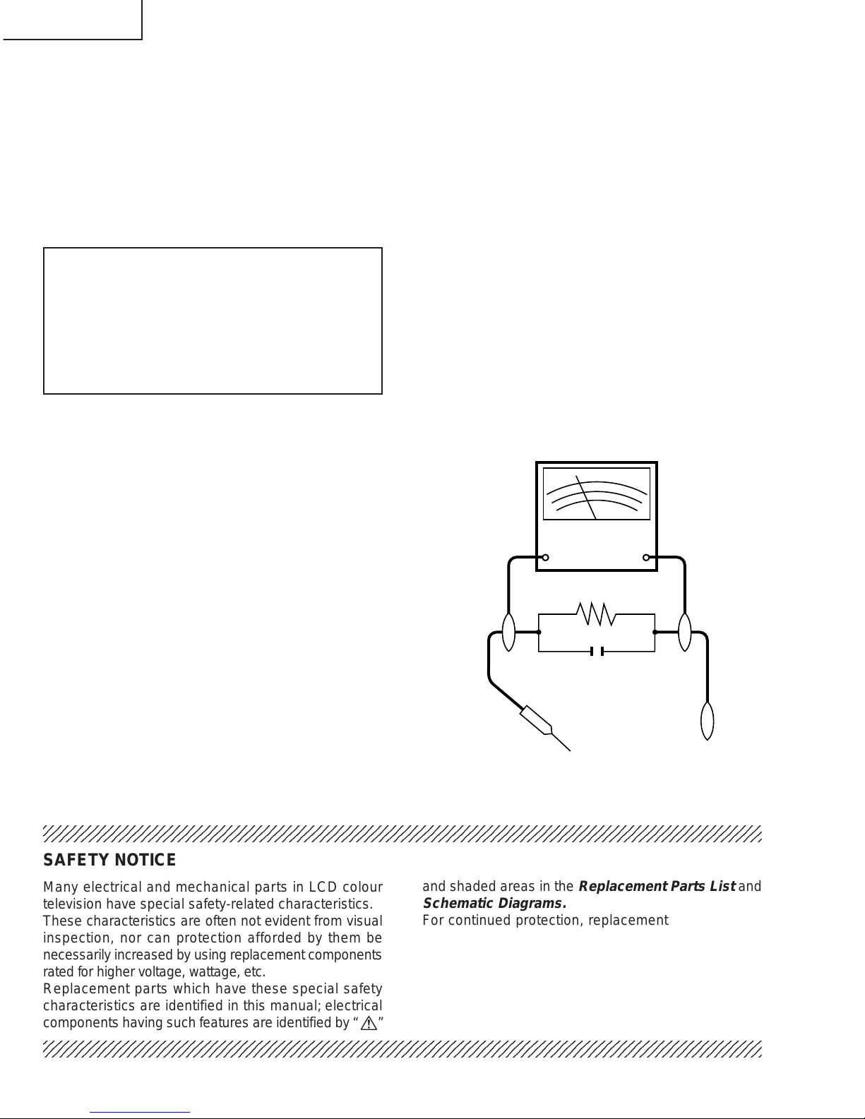
3. To be sure that no shock hazard exists, check for
leakage current in the following manner.
» Plug the AC cord directly into a 220~240 volt A C outlet.
» Using two clip leads, connect a 50k ohm, 10 watt
resistor paralleled by a 0.15µF capacitor in series
with all exposed metal cabinet parts and a known
earth ground, such as electrical conduit or electrical
ground connected to an earth ground.
» Use an AC voltmeter ha ving with 5000 ohm per v olt,
or higher, sensitivity or measure the A C v oltage drop
across the resistor.
» Connect the resistor connection to all exposed metal
parts having a return to the chassis (antenna, metal
cabinet, screw heads, knobs and control shafts,
escutcheon, etc.) and measure the AC voltage drop
across the resistor.
All checks must be repeated with the AC cord plug
connection reversed. (If necessary, a nonpolarized
adaptor plug must be used only for the purpose of
completing these checks.)
Any reading of 35V peak (this corresponds to 0.7
mA. peak AC.) or more is excessive and indicates a
potential shock hazard which must be corrected
before returning the monitor to the owner.
TO EXPOSED
METAL PARTS
CONNECT TO
KNOWN EARTH
GROUND
IMPORTANT SERVICE SAFETY PRECAUTION
Ë
Service work should be performed only by qualified service technicians who are thoroughly familiar with all safety checks and the servicing guidelines which follow:
DVM
AC SCALE
50k ohm
10W
0.15 µF
TEST PROBE
Page 3
3
LC-37HV4EB, AN-37U4-B
AN-37L4-T, AN37W4K
Precautions for using lead-free solder
1 Employing lead-free solder
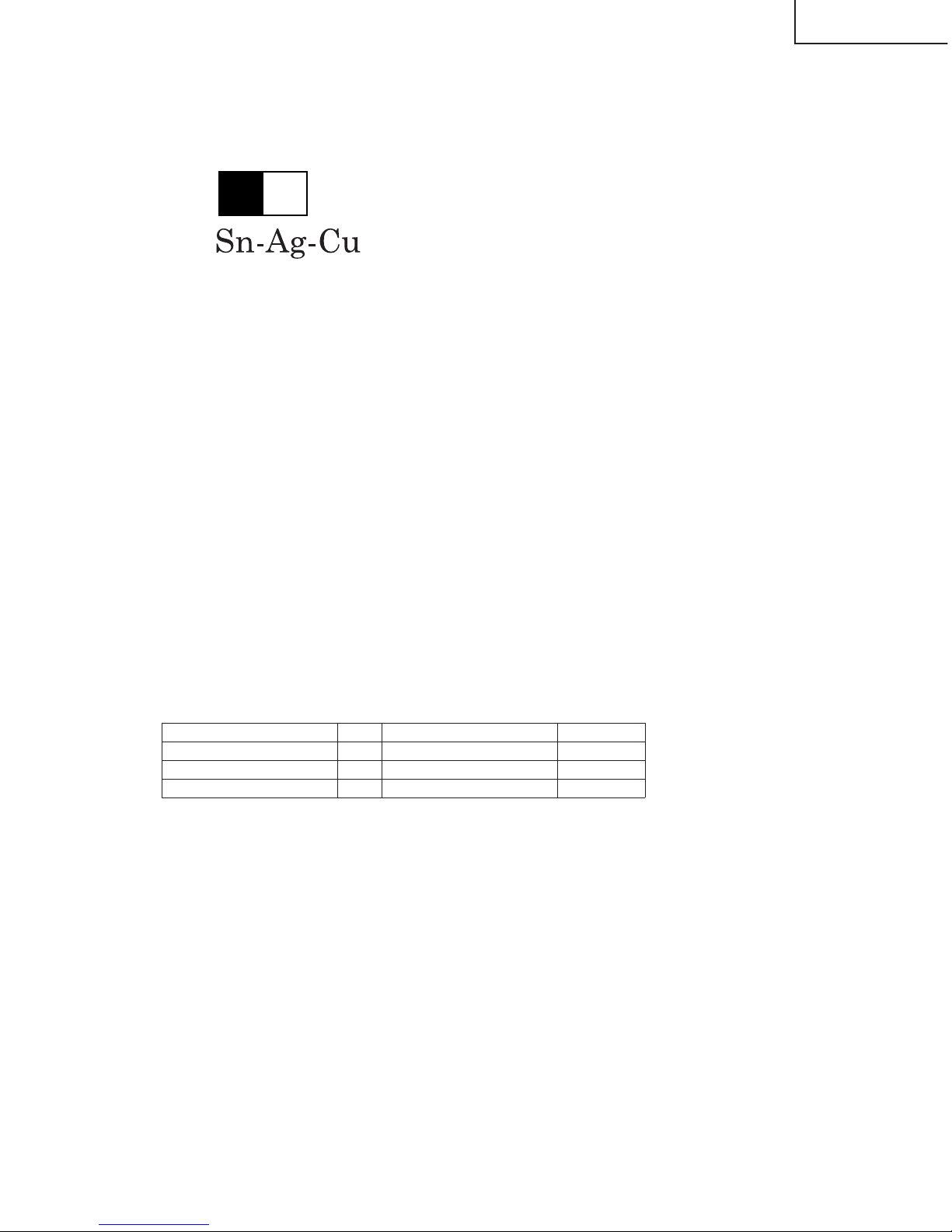
"PWBs" of this model employs lead-free solder. The LF symbol indicates lead-free solder, and is attached on the
PWBs and service manuals. The alphabetical character following LF shows the type of lead-free solder.
Example:
2 Using lead-free wire solder
When fixing the PWB soldered with the lead-free solder, apply lead-free wire solder. Repairing with conventional
lead wire solder may cause damage or accident due to cracks.
As the melting point of lead-free solder (Sn-Ag-Cu) is higher than the lead wire solder by 40°C, we recommend
you to use a dedicated soldering bit, if you are not familiar with how to obtain lead-free wire solder or soldering bit,
contact our service station or service branch in your area.
3 Soldering
As the melting point of lead-free solder (Sn-Ag-Cu) is about 220°C which is higher than the conventional lead
solder by 40°C, and as it has poor solder wettability, you may be apt to keep the soldering bit in contact with the
PWB for extended period of time. However, Since the land may be peeled off or the maximum heat-resistance
temperature of parts may be exceeded, remov e the bit from the PWB as soon as you confirm the steady soldering
condition.
Lead-free solder contains more tin, and the end of the soldering bit may be easily corroded. Make sure to turn on
and off the power of the bit as required.
If a different type of solder stays on the tip of the soldering bit, it is allo y ed with lead-free solder. Clean the bit after
every use of it.
When the tip of the soldering bit is blackened during use, file it with steel wool or fine sandpaper.
Be careful when replacing parts with polarity indication on the PWB silk.
Indicates lead-free solder of tin, silver and copper.
Lead-free wire solder for servicing
Part No, ★ Description Code
ZHNDAi123250E J φ0.3mm 250g(1roll) BL
ZHNDAi126500E J φ0.6mm 500g(1roll) BK
ZHNDAi12801KE J φ1.0mm 1kg(1roll) BM
L Fa
Page 4
4
LC-37HV4EB, AN-37U4-B
AN-37L4-T, AN37W4K
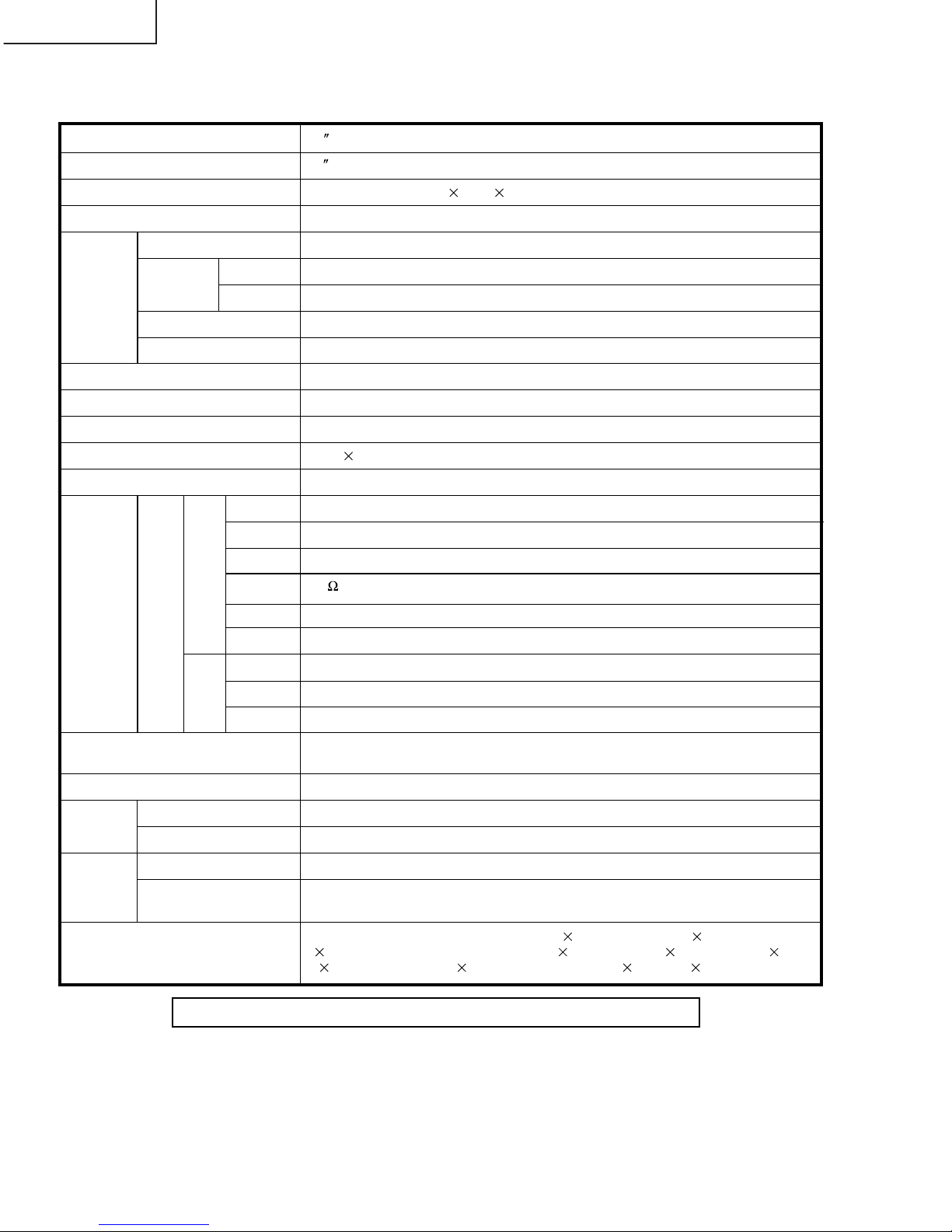
SPECIFICATIONS
Item 37 LCD COLOUR TV, Model:LC-37HV4EB
Video Colour System PAL/SECAM/NTSC 3.58/NTSC 4.43/PAL 60
TV
Function
B/G, D/K, I, L/L’
VHF/UHF
E2–E69ch, F2–F10ch, I21–I69ch, IR A–IR Jch
CATV
Hyper-band, S1–S41ch
TV-Tuning System
Auto Preset 99 ch, Auto Label, Auto Sort
STEREO/BILINGAL NICAM/IGR
Terminals SCART (AV in, RGB in, TV out)
INPUT 2
SCART (AV in/out, S-VIDEO in, AV Link)
INPUT 3
SCART (AV in/out, S-VIDEO in, RGB in), Component
ANTENNA 75
Din Type
INPUT 4 S-VIDEO, AV in
PC
15 Pin mini D-Sub, Audio in (Ø 3.5mm jack)
OSD language
English/German/French/Italian/Spanish/Dutch/Swedish/Portuguese/Greek/
Finnish/Russian/Turkish
Power Requirement
AC 220–240 V, 50/60 Hz
Power
Consumption
32 W (0.7W Standby)
Weight
5.4 kg (w/o stand), 5.5 kg (with stand)
Accessories
Operation manual, Remote control unit (
1), System cable ( 1), AC cord
(
2), LR6 (“AA” size) Alkaline battery ( 2), Stand unit ( 1), Speaker (L 1,
R
1), Speaker screw ( 4), Cable clamp (Large 1, Small 2)
TV-standard (CCIR)
Receiving
Channel
Rear INPUT 1
Front
LCD panel 37 Advanced Super View & BLACK TFT LCD
Number of dots 3,147,264 dots (1366 768 3 dots)
Brightness 430 cd/m
2
Backlight 60,000 hours (at Manual 0 position)
Viewing angles H : 170° V : 170°
Audio amplifier 10W
2
Speakers Ø 8 cm 2pcs
AVC
System
AV OUTPUT Audio (Variable, Fixed), S-VIDEO out, AV out
Headphones
Ø 3.5mm jack
AVC System
Display
AVC System
Display
138 W (0.9W Standby) (Method IEC60107)
16.5 kg (Display only), 19.9 kg (with Display and speakers), 24.0 kg (with
Display, speakers and stand)
DC OUTPUT DC6.5V 7W MAX
Specifications are subject to change without prior notice.
Page 5
5
LC-37HV4EB, AN-37U4-B
AN-37L4-T, AN37W4K
OPERATION MANUAL
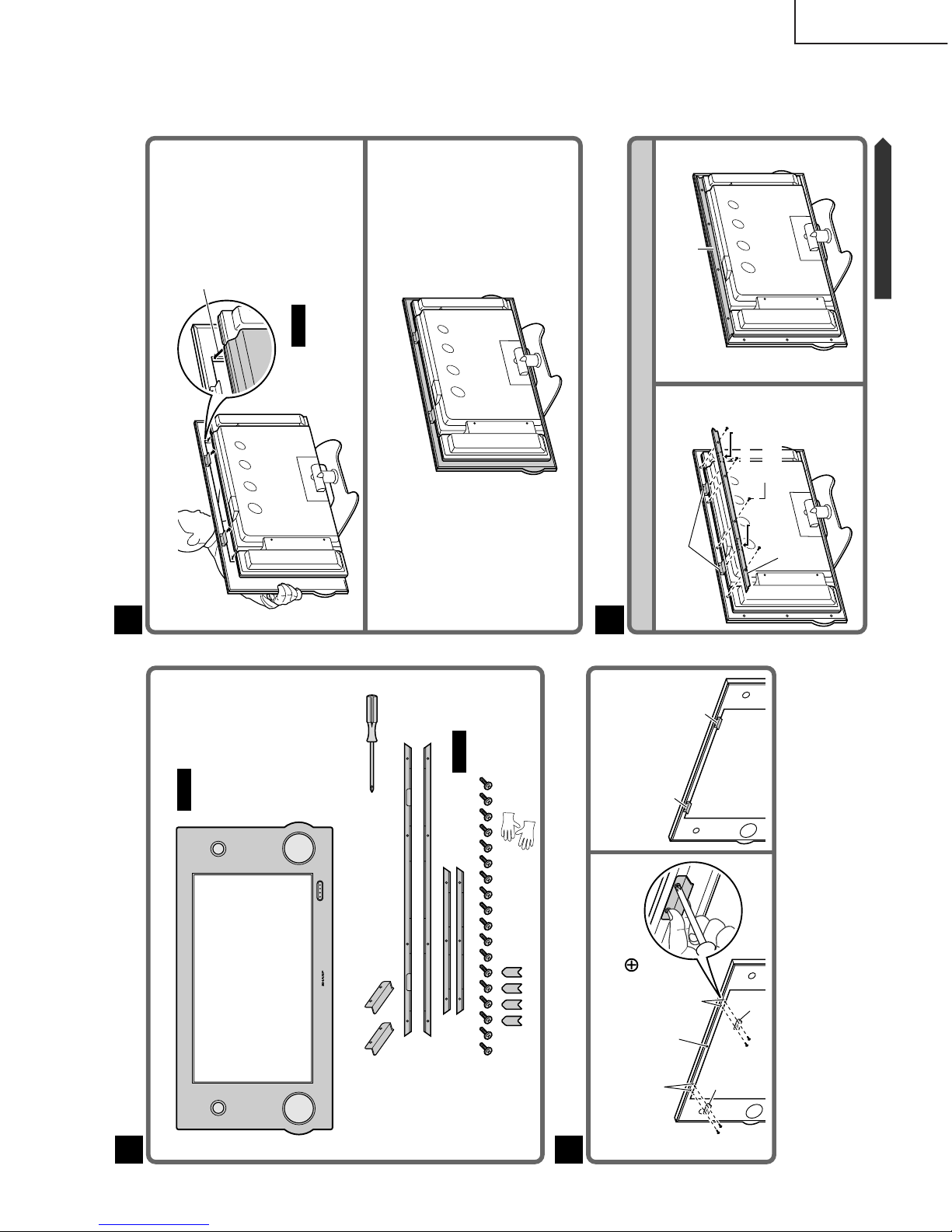
Confirming the Accessories1
2
Attaching the Fittings to the Customized Frame
2
Attach the fittings to the upper screw
holes on the rear of the customized frame
with the screws (Use the
driver)
Diagram showing both
fittings attached
1
Accessories for mounting
Fittings (× 2)
Top frame ( × 1)
Bottom frame (× 1)
Left and right frames
(× 1 each)
Screws ( × 18)
Corner decorations
( × 4)
Customized frame
2
Tools for mounting
Screw driver (m1)
• It is recommended that
the gloves supplied are
worn when mounting
the customized frame to
prevent fingerprints. As
the gloves are slippery ,
carry out this operation
with care.
Caution
Screw holes for
attachment
• Wear the gloves
supplied when
assembling the
frame to protect
it from soiling
and damage.
Caution
Upper rear of the
customized frame
Screw holes for
attachment
Fitting
Screw
FittingScrew
Fitting
Fitting
Gloves (m2)
Attaching the Customized Frame to the Unit3
Hook the fittings onto the upper rim of the unit
1
2
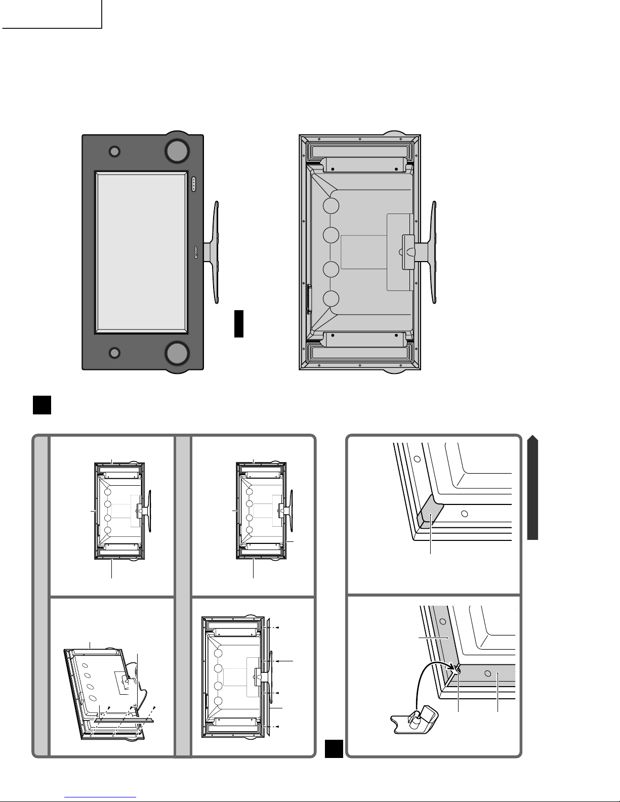
Attaching the Frames onto the Rear of the Customized Frame
4
Diagram showing the attached
top frame
12
Attaching the top frame (long frame with two indentations on its rear)
Diagram showing the customized frame attached to the unit
2
Attach so that the LCD TV
itself fits into the lateral
grooves on the rear of the
customized frame.
• This is to be carried out
after the speakers have
been attached to the unit.
Top frame
Continued on the next page
Align the indentations on the rear
of the frame with the fittings
Caution
Screw
Topframe
Screw
Attach this area
first without fail
Screw
Indentation
Screw
Indentation
Page 6
6
LC-37HV4EB, AN-37U4-B
AN-37L4-T, AN37W4K
Attaching the left and right frames (short frames)
Attaching the bottom frame
Diagram showing the attached
left and right frames
34
Diagram showing the attached
bottom frame
56
2
Attaching the Corner Decorations onto the Frame
5
Diagram showing the attached
corner decoration
•Attach the other corners in the same
way
2
Attach so that the projecting part
on the rear of the corner
decoration fits into the slot on
the frame
1
Attach the
right frame
in the same
way
Attach this area
first without fail
Left frame
Screw
Left
frame
Top frame
Right
frame
Screw
Bottom
frame
Attach this area
first without fail
Left
frame
Bottom
frame
Top frame
Right
frame
Left frame
Top frame
Slot
Corner
decoration
Screw
Screw
Screw
Screw Screw
Continued on the next page
Completed Diagram6
Front
Back
• The display cannot be tilted after the customized
frame has been fitted. Be careful not to damage
the unit itself by trying to move it.
Caution
Page 7

7
LC-37HV4EB, AN-37U4-B
AN-37L4-T, AN37W4K
Unit:mm
Display
DIMENSIONS
Page 8

8
Ref. No. Part No. ★ Description Code Ref. No. Part No. ★ Description Code
LC-37HV4EB, AN-37U4-B
AN-37L4-T, AN37W4K
1 CANGTA037WJ05 J Rear Panel Ass’y
1-1
Not Available
– Rear Panel —
1-2 HiNDPA780WJSA J Indication Label AP
2 CCABAA289WJ01 J Chassis Flame Ass’y BB
2-1
Not Available
– Chassis Flame —
2-2
Not Available
– Stand Angle —
2-3 LHLDW1021GE00 J Wire Holder, x2 AB
2-4 LHLDW1139CEZZ J Wire Holder, x1 AA
2-5 PZETZA008WJZZ J Insulating Sheet AK
2-6 QEARZA020WJFW J Earth Spring, x2 AC
2-7 XJPSN30P08XS0 J Screw, x2 AA
3 CCABBA111WJ05 J Bottom Cabinet Ass’y BD
3-1
Not Available
– Bottom Cabinet —
3-2 GLEGGA012WJZZ J Leg, x4 AD
4 CCABBA170WJ02 J Top Cabinet Ass’y AY
4-1
Not Available
– Top Cabinet —
4-2 TCAUHA049WJZZ J Caution Label AD
5 CANGTA023WJ01 J PC I/F Bottom Shield Ass’y AQ
5-1
Not Available
– PC I/F Bottom Shield —
5-2 LHLDW1021GE00 J Wire Holder, x1 AB
5-3 PFLT-A004WJZZ J Spacer, x1 AE
6 CPNLCA066WJ02 J Front Panel Ass’y BH
6-1
Not Available
– Front Panel —
6-2 GCOVAA288WJSB J Door Cover AX
6-3 GDORFA018WJSB J Door AN
6-4 HBDGBA013WJSC J Badge, "SHARP" AP
6-5 HDECQA166WJSA J LED Cover AF
6-6 HiNDPA290WJSB J Indication Label AH
6-7 JBTN-2074CEKB J Power Button AG
6-8 LANGF9552CESA J Angle, for Door AC
6-9 LANGTA024WJFW J Angle, for Damper AE
6-10 LANGTA047WJFW J Angle AC
6-11 LHLDZ3040GEZZ J Magnet Holder AD
6-12 LHLDZA138WJZZ J Button Holder AE
6-13 LX-BZ3434CEFN J Screw, x2 AB
6-14 MSPRC0210CEFW J Spring, for Power Button AB
6-15 PCOVPA014WJSB J Door Cover AK
6-16 PDMPFA001WJZZ J Damper AG
6-17 PSPAZ0457CESA J Spacer, for Door, x2 AA
6-18 XBPSN20P05000 J Screw, x2 AA
6-19 XEBSN30P08000 J Screw, x4 AA
PARTS LIST
PARTS REPLACEMENT
Replacement parts which have these special safety characteristics
identified in this manual: electrical components having such features are identified by "å" in the Replacement Parts Lists.
The use of a substitute replacement part which does not have the
same safety characteristics as the factory recommended replacement parts shown in this service manual may create shock, fire or
other hazards.
"HOW TO ORDER REPLACEMENT PARTS"
To have your order filled promptly and correctly, please furnish the
following informations.
1. MODEL NUMBER 2. REF. NO.
3. PART NO. 4. DESCRIPTION
5. CODE 6. QUANTITY
★ MARK : SPARE PARTS-DELIVERY SECTION
CABINET AND MECHANICAL PARTS
(AVC System)
Ref. No. Part No. ★ Description Code
7 CSLDMA157WJ01 J PC I/F Top Shield Ass’y
7-1
Not Available
– PC I/F Top Shield —
7-2 PSPAKA019WJZZ J Spacer AF
8 GCOVAA243WJSB J Side Cover(L) AP
9 GCOVAA244WJSB J Side Cover(R) AN
10 LANGTA022WJFW J PWB Angle, for MAIN Unit AN
11 LANGTA028WJFW J Inlet Angle AH
12 LANGTA039WJFW J PWB Angle, for AV Unit AP
13 LHLDW1009CEZZ J Wire Holder, x1 AA
14 LHLDW1033CEKZ J Wire Holder, x1 AA
15 LHLDW1060CEZZ J Wire Holder, x2 AB
16 LHLDW1121GEZZ J Wire Holder, x1 AB
17 LHLDZ2156CEN2 J Fan Holder AH
18 LX-BZ3434CEFN J Screw, x2 AB
19 NFANR0120CEZZ J Cooling Fan AU
20 NSFTZ0134CEFW J Shaft Screw, x8 AD
21 PSLDM4715CEFW J Earth Shield AD
22 PSLDMA144WJFW J Front Shield AQ
23 PSPAZA121WJKZ J Radiating Sheet AT
24 PSPAZA122WJKZ J Radiating Sheet AK
25 DUNTKB401FE03 – MAIN Unit —
26 DUNTKB493FE03 – POWER Unit —
27 DUNTKB592FE01 – AV Unit —
28 DUNTKB593DE21 – FRONT Unit —
29 DUNTKB594DE21 – SR Unit —
30 CPCi-A005WJ11 – PC I/F Unit —
31 QCNW-A847WJZZ J Connecting Cord(Main-AV) AD
32 QCNW-A848WJZZ J Connecting Cord AD
(Main-PC I/F)
33 QCNW-A849WJZZ J Connecting Cord AC
(Main-PC I/F)
34 QCNW-A833WJZZ J Connecting Cord(Front-AV) AE
35 QCNW-A838WJZZ J Connecting Cord AK
(Front-PC I/F)
36 QCNW-A828WJZZ J Connecting Cord(AV-SR) AK
37 QCNW-A844WJZZ J Connecting Cord AM
(PC I/F-SR)
38 QCNW-A825WJZZ J Connecting Cord AK
(Main-Power)
39 QCNW-A826WJZZ J Connecting Cord AG
(Main-Power)
40 QCNW-A846WJZZ J Connecting Cord AH
(Power-PC I/F)
41 QCNW-A822WJZZ J Connecting Cord(Main-AV) AF
42 QCNW-A823WJZZ J Connecting Cord(Main-AV) AM
43 QCNW-A824WJZZ J Connecting Cord(Main-AV) AQ
44 QEARZ0056CEFW J Earth Angle, x4 AC
45 QEARZ0057CEFW J Earth Angle, x1 AB
46 CEARZA023WJ01 J Earth Angle, x1 AL
47 CEARZA024WJ01 J Earth Angle, x1 AM
48
Not Available
– Serial No. Label —
49 XBBSN30P06000 J Screw, x2 AA
50 XBPSN30P06000 J Screw, x6 AA
51 XEBS930P08000 J Screw, x6 AA
52 XJPSN30P08XS0 J Screw, x38 AA
53 XJPS930P08XS0 J Screw, x15
Page 9

9
LC-37HV4EB, AN-37U4-B
AN-37L4-T, AN37W4K
654321
A
B
C
D
E
F
G
H
CABINET AND MECHANICAL PARTS (AVC System)
15
47
1-1
1-2
1
8
52
2-3
2-5
2-6
44
44
2-3
2-4
2-1
2-7
2-2
52
53
19
3
6
27
20
18
48
50
50
9
53
4
21
45
52
28
46
17
53
6-19
3-2
3-1
53
6-9
6-16
6-18
6-19
6-10
6-12
6-19
6-5
53
6-1
6-4
6-14
6-7
6-8
6-6
6-3
6-11
6-17
6-13
6-15
6-2
12
36
52
5-2
5-1
5-3
29
5
35
52
33
32
40
30
52
7-2
23
24
7-1
52
7
41
38
16
31
10
52
52
25
42
52
53
4-1
4-2
53
53
43
37
49
11
52
39
14
26
34
52
53
52
22
20
52
51
AB
AD
AE
AA
AF
C
D
C
B
A
AB
L
L
AD
E
D
E
J
H
K
M
L
J
F
E
AE
K
AA
L
B
A
M
H
F
E
AF
Page 10

10
LC-37HV4EB, AN-37U4-B
AN-37L4-T, AN37W4K
654321
A
B
C
D
E
F
G
H
CABINET AND MECHANICAL PARTS (Display)
3-1
60
3
1
5
62
37
3-5
3-3
3-6
5-5
5-21
5-22
5-18
5-19
5-19
5-20
5-27
5-24
5-14
5-15
5-13
5-12
5-27
5-26
5-6
5-6
5-25
5-18
5-24
3-4
1-2
1-6
1-1
1-8
1-4
1-7
1-3
1-6
5-23
5-16
5-1
1-7
3-7
3-2
5-4
5-3
5-5
5-11
5-10
5-2
2-7
8
54
9
57
55
56
63
65
5-8
5-9
2-3
2-8
2-8
2-2
2-1
5-9
5-8
5-25
5-26
2-5
2-4
68
44
42
51
38
43
2-6
4-6
4-2
4-3
4-5
4-1
4-4
66
17
13
4
29
66
68
7
7-2
7-1
64
47
48
41
24
25
68
46
28
18
59
11
19
34
66
45
67
64
35
23
40
14
2-9
5-7
1-5
5-17
5-17
5-17
5-17
5-17
12
16
27
2
10
68
66
68
66
68
50
6
32
6-2
6-1
33
68
36 61
23
39
30
49
13
31
15
67
53
26
4-7
4-8
4-9
4-12
4-10
4-13
4-11
A
A
22
20
69
21
20
69
Page 11

11
Ref. No. Part No. ★ Description Code Ref. No. Part No. ★ Description Code
LC-37HV4EB, AN-37U4-B
AN-37L4-T, AN37W4K
5-25 XHPSD30P10JS0 J Screw, x2 AB
5-26 XHPSF30P12JS0 J Screw, x4 AB
5-27 XHPSN30P08JS0 J Screw, x16 AB
5-28 LX-BZA048WJFN J Screw, x2
5-29 LX-EZA007WJFN J Screw, x2 AB
6 CHLDZA177WJ01 J FPC Holder(L) Ass’y AP
6-1
Not Available
– FPC Holder(L) —
6-2 LHLDWA024WJZZ J Wire Holder, x3 AD
7 CHLDZA177WJ02 J FPC Holder(R) Ass’y AP
7-1
Not Available
– FPC Holder(R) —
7-2 LHLDWA024WJZZ J Wire Holder, x3 AD
8 GCOVAA226WJKB J Terminal Cover(Up) AW
9 GCOVAA235WJKB J Terminal Cover(Bottom) AX
10 GCOVAA236WJKB J Panel Link Cover AG
11 LANGKA076WJFE J Reinforcement Angle AM
12 LHLDW1046CEZZ J Holder AA
13 LHLDW1076GEZZ J Wire Holder, x3 AA
14 LHLDWA012WJKZ J Wire Holder, x1 AC
15 LHLDWA013WJKZ J Wire Holder, x3 AC
16 PFLT-A007WJZZ J Spacer AG
17 PZETKA019WJKZ J Insulating Sheet AR
18 PZETKA030WJKZ J Insulating Sheet AG
19 PZETKA037WJKZ J Insulating Sheet AN
20 CPNLSA006WJ01 J Speaker Panel, x2 AZ
21 RSP-ZA062WJN1 J Speaker Unit(L) BM
22 RSP-ZA062WJN2 J Speaker Unit(R) BM
23 GCOVAA240WJKB J Speaker Terminal Cover, x2
24 LX-BZ3434CEFN J Screw, x2 AB
25 NSFTZ0134CEFW J Shaft Screw, x2 AD
26 PFLT-A008WJZZ J Conductive Spacer, x2 AE
27 PSLDMA175WJ01 J Shield, for Main Unit AT
28 PSLDMA176WJFN J Panel Link Shield AK
29 PSPAHA151WJZZ J Spacer AB
30 DKEYHB453FE52 – MAIN Unit —
31 DUNTKB460DE02 – AUDIO Unit —
32 DUNTKB809DE01 – INVERTER-1 Unit —
33 DUNTKB810DE01 – INVERTER-3 Unit —
34 DUNTKB811DE01 – INVERTER-2 Unit —
35 DUNTKB812DE01 – INVERTER-4 Unit —
36 DUNTKB813DE01 – R/C, LED Unit —
37 DUNTKB814DE01 – KEY Unit —
38 RDENCA033WJZZ – POWER Unit —
39 DUNTKB461DE02 – SPEAKER-L Unit —
40 DUNTKB462DE02 – SPEAKER-R Unit —
41 QCNW-A966WJZZ J Connecting Cord AE
(Main-INV1)
42 QCNW-A967WJZZ J Connecting Cord AG
(Power-INV1/2)
43 QCNW-A968WJZZ J Connecting Cord AK
(Power-INV3/4)
44 QCNW-A969WJZZ J Connecting Cord AG
(Power-Main)
45 QCNW-A970WJZZ J Connecting Cord AF
(Power-Audio)
46 QCNW-A971WJZZ J Connecting Cord AK
(Main-Audio)
47 QCNW-A972WJZZ J Connecting Cord(Main-Key) AE
48 QCNW-A973WJZZ J Connecting Cord AK
(Main-RC/LED)
49 QCNW-B010WJZZ J Connecting Cord AE
(Main-INV3)
50 QCNW-B088WJZZ J Connecting Cord AF
(Audio-INV4)
51 QCNW-B223WJZZ J
Connecting Cord(Power-Key)
AM
52 QCNW-B250WJZZ J Connecting Cord AM
(INV1-INV3)
53 RCORFA012WJZZ J Ferrite Core AG
54
Not Available
– Serial No. Label —
55 XBBS930P08000 J Screw, x2 AA
56 XBBS950P12000 J Screw, x2 AB
57 XBBSN50P12JS0 J Screw, x4 AF
59 XBSS940P08000 J Screw, x4 AA
1 CCABAA499WJ01 J Front Cabinet Ass’y BN
1-1
Not Available
– Front Cabinet —
1-2 GCOVAA222WJSA J RC/LED Cover AG
1-3 HBDGBA010WJSB J Badge, "SHARP" AL
1-4 PMLT-A059WJZZ J Spacer, x1 AD
1-5 PSPAG0432CEUZ J Spacer, x2 AA
1-6 PSPAHA078WJZZ J Spacer, x2 AD
1-7 PSPAHA079WJZZ J Spacer, x2 AG
1-8 QCNW-A974WJZZ J Connecting Cord(SP) AE
2 CCABBA144WJ06 J Rear Cabinet Ass’y BT
2-1
Not Available
– Rear Cabinet —
2-2 GCOVAA454WJKC J Cover, x4 AC
2-3 HiNDP5733CESD J "AQUOS" Label AD
2-4 HiNDP5971CESB J
Speaker Indication Label, x2 AC
2-5 HiNDPA738WJSA J Model Label AG
2-6 HiNDP A285WJSB J Speaker Terminal AE
Indication Label
2-7 HiNDPA286WJSB J Cable Indication Label AE
2-8 LHLDZ0132CEZZ J
Speaker Attaching Holder, x4
AD
2-9 PCOVUA008WJZZ J Cover, x2 AD
3 CCOVAA286WJ05 J Top Operation Cover Ass’y AY
3-1
Not Available
– Top Operation Cover —
3-2 GCOVAA259WJKA J Operation Button Cover, x2 AE
3-3 JBTN-A072WJKA J Power Button AL
3-4 JBTN-A097WJKA J Operation Button AL
3-5 MSPRCA015WJFW J Power Button Spring AB
3-6 PSPAGA024WJZZ J Spacer AB
3-7 XEBSN30P08000 J Screw, x2 AA
4 CDAi-0105CE03 J Stand BZ
4-1 CDAi-0105CESB J Stand, Base BB
4-2 GDAi-3056CESB J Stand, Joint AT
4-3 GDAi-A049WJSB J Stand, Support Angle AU
4-4 LANGKA073WJSA J Base Angle BD
4-5 LX-BZ3441CEFN J Nut, x1 AD
4-6 MHNG-A037WJSA J Hinge BR
4-7 PSPAZA092WJZZ J Leg Cushion-A, x4 AD
4-8 PSPAZA096WJZZ J Leg Cushion-B, x1 AD
4-9 PSPAZA097WJZZ J Leg Cushion-C, x2 AC
4-10 XCBS950P25000 J Screw, x5 AC
4-11 XCSSN50P25000 J Screw, x4 AB
4-12 XEBS940P08000 J Screw, x12 AB
4-13 XWHSF50-16120 J Washer, x5 AB
5
Not Available
– 37" LCD Panel Unit Ass’y —
5-1 RLCDTA018WJZZ J 37" LCD Panel Unit HG
å 5-2 KLMP-A025WJZZ J Fluorescent Lamp, x7 BB
5-3 LANGKA078WJ01 J Sheet Fixing Angle AP
5-4 LANGKA078WJFW J Sheet Fixing Angle(Top) AL
5-5 LANGKA079WJFW J
Sheet Fixing Angle(Side), x2
AH
5-6 LANGKA163WJFW J Panel Receptacle Angle, x2 AD
5-7 LCHSMA015WJZZ J Chassis Frame BZ
5-8 LHLDZA099WJKZ J
Lamp Fixing Holder(Bottom), x2
AN
5-9 LHLDZA100WJKZ J Lamp Fixing Holder(Top), x2AP
5-10 LHLDZA101WJKZ J Lamp Clip, x7 AD
5-11 PCOVUA004WJZZ J Diffusion Panel BF
5-12 PMiR-A011WJZZ J Reflection Mirror BR
5-13 PSHEPA048WJZZ J Diffusion Sheet AX
5-14 PSHEPA049WJZZ J Deflection Sheet CD
5-15 PSHEPA050WJZZ J Prism Sheet BR
5-16 PSLDMA127WJZZ J Shield AH
5-17 PSPAHA111WJZZ J Spacer, x6 AC
5-18 QCNW-A480WJZZ J Connecting Cord, x2 AM
5-19 QCNW-A481WJZZ J Connecting Cord, x2 AM
5-20 QCNW-A976WJZZ J Connecting Cord AK
5-21 QCNW-B063WJZZ J Connecting Cord AL
5-22 RCORFA007WJZZ J Ferrite Core, x4 AK
5-23 XBPSN40P10JS0 J Screw, x6 AB
5-24 XEBSN30P08000 J Screw, x6 AA
CABINET AND MECHANICAL PARTS
(Display)
Page 12

12
Ref. No. Part No. ★ Description Code Ref. No. Part No. ★ Description Code
LC-37HV4EB, AN-37U4-B
AN-37L4-T, AN37W4K
60 XEBSN30P06000 J Screw, x2 AA
61 XEBSN30P08000 J Screw, x2 AA
62 XEBSN30P10000 J Screw, x3 AA
63 XEBS930P10000 J Screw, x3 AA
64 XEBS940P16000 J Screw, x3 AA
65 XEBS940P20000 J Screw, x13 AB
66 XHPSN30P10JS0 J Screw, x8 AB
67 XHPS930P12JS0 J Screw, x2 AB
68 XHPS930P08JS0 J Screw, x25 AB
69 PCOVPA019WJZZ J Speaker Cap, x2 AP
CABINET AND MECHANICAL PARTS
(Display)(Continued)
SUPPLIED ACCESSORIES
RCORFA020WJZZ J Ferrite Core AN
TCAUZA037WJZZ J Caution Sheet AD
TiNS-A476WJZZ J Operation Manual BA
LHLDW0110CESB J Wire Holder(Large), x1 AE
LHLDZ0139CEZZ J Wire Holder(Small), x2 AD
XBBS940P25000 J Speaker Screw, x4 AA
RRMCGA026WJSA J Remote Control Unit AZ
å QACCKA007WJPZ J AC Cord, x2 (LC-37HV4E) AN
å QACCBA022WJPZ J AC Cord, x2
(LC-37HV4E(K))
AS
GDAi-A059WJSB J Stand(for AVC System) AW
GLEGGA013WJZZ J Stand Cushion, x4 AC
PSPAHA101WJZZ J Stand Spacer, x4 AB
XBPSN40P14JS0 J Stand Screw, x2 AB
QCNW-6117CEZZ J System Cable BP
TGAN-1688CEN1 J Guarantee Card AN
(LC-37HV4E(K))
Page 13

13
Ref. No. Part No. ★ Description Code Ref. No. Part No. ★ Description Code
LC-37HV4EB, AN-37U4-B
AN-37L4-T, AN37W4K
SERVICE JIGS
(Use for servicing)
QCNW-A407WJZZ J Extension Cable, 30-pin AW
(SC1501-PC I/F)
QCNW-A408WJZZ J Extension Cable, 50-pin AW
(SC1502-PC I/F)
QCNW-6102CEZZ J Extension Cable, 13-pin AL
(P1701-PC I/F)
QCNW-6103CEZZ J Extension Cable, 12-pin AV
(P2401-PC I/F)
QCNW-A437WJZZ J Extension Cable, 50-pin, x2 AL
(SC4601-LCD)
(SC4602-LCD)
QCNW-A438WJZZ J Extension Cable, 53-pin, x2 AL
(SC4603-LCD)
(SC4604-LCD)
QCNW-B242WJZZ J Extension Cable, 30-pin, x2 AZ
(CN4101-LCD)
(CN4102-LCD)
QCNW-B244WJZZ J Extension Cable, 5-pin AM
(CN7704-INV1)
QCNW-B245WJZZ J Extension Cable, 6-pin AN
(CN7705-INV3)
QCNW-B246WJZZ J Extension Cable, 7-pin AP
(CN7707-POW)
QCNW-B247WJZZ J Extension Cable, 4-pin AM
(CN4701-INV1/2)
QCNW-B248WJZZ J Extension Cable, 4-pin AM
(CN3702-INV3/4)
SPAKCB122WJZZ – Packing Case —
SPAKFA137WJZZ – Packing Material, —
for Speaker(R)
SPAKFA138WJZZ – Packing Material, —
for Speaker(L)
SPAKFA236WJZZ – Packing Material —
(AVC System)
SPAKFA237WJZZ –
Packing Case(Accessory)
—
SPAKL0023CEZZ – Joint, x4 —
SPAKPA173WJZZ – Wrapping Paper —
(Display Side)
SPAKPA092WJZZ –
Wrapping Paper(Stand Side)
—
SPAKPA093WJZZ – Wrapping Paper, —
for Speaker(R)
SPAKPA094WJZZ – Wrapping Paper, —
for Speaker(L)
SPAKPA142WJZZ – Wrapping Paper —
(AVC System)
SPAKXA156WJZZ – Buffer Material(Top) —
SPAKXA185WJZZ – Buffer Material(Bottom) —
SSAKA0160CEZZ – Polyethylene Bag —
SSAKA0219CEZZ – Polyethylene Bag —
SSAKA1111CEZZ – Polyethylene Bag —
TLABK0001TAZZ – No. Label, x2 —
TLABK0023TAZZ – No. Label —
PACKING PARTS
(NOT REPLACEMENT ITEM)
Page 14

14
LC-37HV4EB, AN-37U4-B
AN-37L4-T, AN37W4K
654321
A
B
C
D
E
F
G
H
CABINET AND MECHANICAL PARTS (Customized Frame)
78
1-2-7
1-2-1
1-2-3
1-2-5
1-2-4
1-3
1-7
5
99
1-2-7
1-2-1
1-2-3
1-2-5
1-2-4
1-2-6
1-3
1-6
1-8
1-5
1-4
9
1
9
9 9
3
9
9
5
22
4
6
6
6
6
9
9
Page 15

15
Ref. No. Part No. ★ Description Code Ref. No. Part No. ★ Description Code
LC-37HV4EB, AN-37U4-B
AN-37L4-T, AN37W4K
1 CWAKWA001WJ03 J Customized Frame Ass’y FH
(AN-37U4-B)
1 CWAKWA002WJ03 J Customized Frame Ass’y FU
(AN-37L4-T)
1 CWAKWA003WJ03 J Customized Frame Ass’y EE
(AN-37W4K)
1-1
Not Available
– Customized Frame —
1-2 CHLDZA220WJ01 J Speaker Holder Ass’y, x2 BL
1-2-1 LHLDZA221WJSA J Speaker Net Holder, x2 BD
1-2-3 PSPAZA277WJZZ J Spacer-A, x2 AE
1-2-4 PSPAZA278WJZZ J Spacer-B, x2 AD
1-2-5 PSPAZA279WJZZ J Spacer-C, x2 AD
1-2-6 LHLDZA220WJSA J Speaker Holder, x2 BC
1-2-7 XEBSF30P08000 J Screw, x6 AA
1-3 LHLDZA222WJSA J Speaker Net Holder BA
(Small), x2
1-4 9AQLC37U5B-04 J Sheet(Top) AN
1-5 9AQLC37U5B-05 J Sheet(Bottom) AP
1-6 9AQLC37U5B-06 J Sheet(Right) AM
1-7 9AQLC37U5B-07 J Sheet(Left) AM
1-8
Not Available
– Serial No. Label —
2 LANGFA052WJZZ J Fittings, x2 AX
3 GCOVAA477WJSA J Top Frame BV
4 GCOVAA478WJSA J Bottom Frame BS
5 GCOVAA479WJSA J Frame(R/L) BT
6 LBSHZA002WJSA J Corner Decoration, x4 AX
7 HBDGBA010WJSA J Badge, "SHARP" AH
(AN-37L4-T)
7 HBDGBA010WJSB J Badge, "SHARP" AL
(AN-37W4K)
8 HBDGDA001WJSB J Badge, "AQUOS" AZ
(AN-37W4K)
9 XBBSF40P10000 J Screw, x30 AA
CABINET AND MECHANICAL PARTS
(Customized Frame)
PACKING PARTS
(NOT REPLACEMENT ITEM)
9AQLC37U4B-01 – Message Card(AN-37U4-B) —
9AQLC37L4T-01 – Message Card(AN-37L4-T) —
9AQLC37W4K-01 – Message Card(AN-37W4K) —
9AQLC37U4B-02 – Caution Label(AN-37U4-B) —
9AQLC37L4T-02 – Caution Label(AN-37L4-T) —
9AQLC37W4K-02 – Caution Label(AN-37W4K) —
9AQLC37U5B-11 – Model Label(AN-37U4-B) —
9AQLC37L5T-02 – Model Label(AN-37L4-T) —
9AQLC37W5K-02 – Model Label(AN-37W4K) —
9AQLC37U5-K01 – Packing Case(Top) —
9AQLC37U5-K02 – Pad, x3 —
9AQLC37U5-K03 – Buffer Cover —
9AQLC37U5-K04 – Protection Sheet —
9AQLC37U5-K05 – Packing Case(Bottom) —
9AQLC37U5-K14 – Protection Paper —
(AN-37U4-B, AN-37W4K)
9AQLC37U5-K15 – Protection Cloth(AN-37L4-T) —
9AQLC37U5-K07 – Outer Case(Bottom) —
9AQLC37U5-K10 – Buffer Material —
9AQLC37U5-K08 – Pad(Top/Bottom) —
9AQLC37U5-K11 – Polyethylene Bag(L), x3 —
9AQLC37U5-K12 – Polyethylene Bag(S), x2 —
9AQLC37U5-K09 – Sleeve —
9AQLC37U5-K13 – Buffer Material, x2 —
9AQLC37U5B-K06 – Outer Case(Top) —
9AQAN37U4B-03 – Model Label(Large), x1 —
(AN-37U4-B)
9AQAN37U4B-04 – Model Label(Small), x4 —
(AN-37U4-B)
9AQLC37L4T-03 – Model Label(Large), x1 —
(AN-37L4-T)
9AQLC37L4T-04 – Model Label(Small), x4 —
(AN-37L4-T)
9AQLC37W4K-03 – Model Label(Large), x1 —
(AN-37W4K)
9AQLC37W4K-04 – Model Label(Small), x4 —
(AN-37W4K)
9AQLC37U5B-17 – Polyethylene Bag(Fitting) —
9AQLC37U5B-18 – Polyethylene Bag —
(Corner Decoration)
9AQLC37U5B-20 – Polyethylene Bag —
(Screw Driver)
9AQLC37U5B-21 – Polyethylene Bag(Screw) —
9AQLC37U5B-22 – Polyethylene Bag(Glove) —
SUPPLIED ACCESSORIES
LANGFA052WJZZ J Fitting, x2 AX
GCOVAA477WJSA J Top Frame BV
GCOVAA478WJSA J Bottom Frame BS
GCOVAA479WJSA J Frame(L/R) BT
LBSHZA002WJSA J Corner Decoration, x4 AX
XBBSF40P10000 J Screw, x18 AA
9AQLC37U5B-19 J Screw Driver AW
9AQLC37U5B-25 J Glove, x4(AN-37U4-B)
Page 16

16
LC-37HV4EB, AN-37U4-B
AN-37L4-T, AN37W4K
PACKING OF THE SET (AVC System and Display)
Packing Material(AVC System)
(SPAKFA236WJZZ)
Wrapping Paper(AVC System)
(SPAKPA142WJZZ)
Ferrite Core (RCORFA020WJZZ)
Caution Sheet (TCAUZA037WJZZ)
Operation Manual
(TiNS-A476WJZZ)
Wire Holder (Large), x1 (LHLDW0110CESB)
Wire Holder (Small), x2 (LHLDZ0139CEZZ)
Speaker Screw, x4 (XBBS940P25000)
Remote Control Unit (RRMCGA026WJSA)
AC Cord
(QACCKA007WJPZ)(QACCBA022WJPZ)
Stand(for AVC System) (GDAi-A059WJSB)
Stand Cushion, x4 (GLEGGA013WJZZ)
Stand Spacer, x4 (PSPAHA101WJZZ)
Stand Screw, x2 (XBPSN40P14JS0)
System Cable (QCNW-6117CEZZ)
Guarantee Card(LC-37HV4E(K)) (TGAN-1688CEN1)
Buffer Material(Top)
(SPAKFA156WJZZ)
Wrapping Paper(Display Side)
(SPAKPA173WJZZ)
Wrapping Paper(Stand Side)
(SPAKPA092WJZZ)
Packing Material, for Speaker(R)
(SPAKFA137WJZZ)
Speaker Unit(R)
(RSP-ZA062WJN2)
Wrapping Paper, for Speaker(R)
(SPAKPA093WJZZ)
Buffer Material(Bottom)
(SPAKXA185WJZZ)
Joint
(SPAKL0023CEZZ)
Packing Material, for Speaker(L)
(SPAKFA138WJZZ)
Speaker Unit(L)
(RSP-ZA062WJN1)
Wrapping Paper, for Speaker(L)
(SPAKPA094WJZZ)
No. Label
Packing Case
(SPAKCB122WJZZ)
Buffer Material(Top)
(SPAKXA156WJZZ)
Packing Case(Accessory)
(SPAKFA237WJZZ)
Page 17

17
LC-37HV4EB, AN-37U4-B
AN-37L4-T, AN37W4K
PACKING OF THE SET (Customized Frame)
Packing Case(Top)
Packing Case(Bottom)
Model Label
Pad
Buffer Material
Sleeve
Top Frame
Bottom Frame
Frame(L/R)
Operation Manual
Fitting(2 pcs.)
Screw(18 pcs.)
Screw Driver
Corner Decoration(4 pcs.)
Model Label(Large)
Model Label(Small)
Model Label(Small)
Outer Case(Bottom)
Buffer Material
Buffer Material
Pad(Bottom)
Pad(Top)
Outer Case(Top)
Customized Frame
Protection Paper(AN-37U4-B, AN-37W4K)
Protection Cloth(AN-37L4-T)
Caution Label
Protection Sheet
Buffer Cover
Page 18

LC-37HV4EB, AN-37U4-B
AN-37L4-T, AN37W4K
COPYRIGHT © 2003 BY SHARP CORPORATION
ALL RIGHTS RESERVED.
No part of this publication may be reproduced,
stored in a retrieval system, or transmitted in
any form or by any means, electronic, mechanical,
photocopying, recording, or otherwise, without
prior written permission of the publisher.
SHARP CORPORATION
AV Systems Group
Quality & Reliability Control Center
Yaita, Tochigi 329-2193, Japan
TQ1660-S
Dec. 2003 Printed in Japan
SY. KG
Design and Production Information
Design : Japan
Production : Japan
 Loading...