

Page 1
AL-1670
CODE: 00ZAL1670/A1E
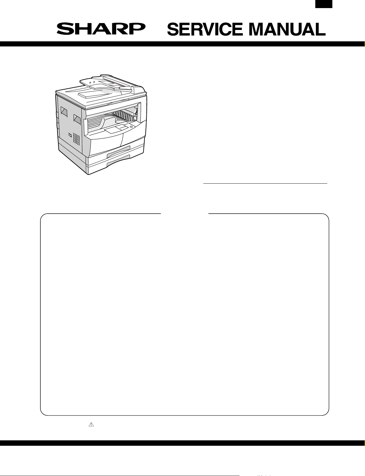
DIGITAL COPIER
AL-1640
AL-1650
MODEL AL-1670
CONTENTS
[ 1 ] INTRODUCTION . . . . . . . . . . . . . . . . . . . . . . . 1 - 1
[ 2 ] DIFFERENT POINTS FROM THE AL-1600 SERIES . . . . 1 - 1
[ 3 ] SPECIFICATIONS . . . . . . . . . . . . . . . . . . . . . . 3 - 1
[ 4 ] LIMITATIONS OF ELECTRICAL SORT <AL-1670 ONLY> . . 4 - 1
[ 5 ] 2 IN 1/4 IN 1 COPY REDUCTION RATIO <AL-1670 ONLY> . . 4 - 1
[ 6 ] SIMULATIONS . . . . . . . . . . . . . . . . . . . . . . . . 6 - 1
[ 7 ] TROUBLE CODE LIST . . . . . . . . . . . . . . . . . . . . 7 - 1
[ 8 ] INSTALLING THE PRINTER DRIVER . . . . . . . . . . . . 8 - 1
[ 9 ] SETTING AND ADJUSTMENTS . . . . . . . . . . . . . . . 9 - 1
[10] CONFIGURATION REPORT AND TEST PAGE . . . . . . 9 - 2
[11] DISASSEMBLY AND ASSEMBLY . . . . . . . . . . . . . 11 - 1
[12] FLASH ROM VERSION UP PROCEDURE . . . . . . . . 12 - 1
Parts marked with “ ” are important for maintaining the safety of the set. Be sure to replace these parts with specified
ones for maintaining the safety and performance of the set.
This document has been published to be used
SHARP CORPORATION
for after sales service only.
The contents are subject to change without notice.
Page 2
AL-1670
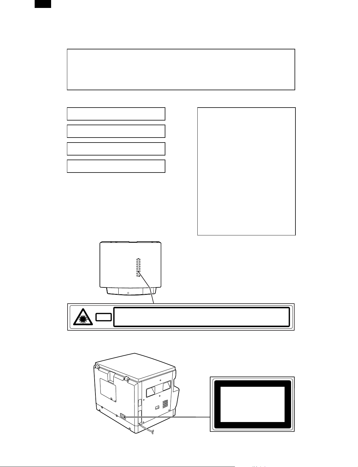
Warning!
This product is a class A product.
If it is operated in households, offices or similar surroundings, it can produce
radio interferences at other appliances, so that the user has to take adequate
countermeasures.
CLASS 1 LASER PRODUCT
LASER KLASSE 1
LUOKAN 1 LASERLAITE
KLASS 1 LASERAPPARAT
VAROITUS!
LAITTEEN KÄYTTÄMINEN MUULLA
KUIN TÄSSÄ KÄYTTÖOHJEESSA
MAINITULLA TAVALLA SAATTAA
ALTISTAA KÄYTTÄJÄN
TURVALLISUUSLUOKAN 1
YLITTÄVÄLLE NÄKYMÄTTÖMÄLLE
LASERSÄTEILYLLE.
VARNING
OM APPARATEN ANVÄNDS PÅ
ANNAT SÄTT ÄN I DENNA
BRUKSANVISNING
SPECIFICERATS, KAN
ANVÄNDAREN UTSÄTTAS FÖR
OSYNLIG LASERSTRÅLNING,
SOM ÖVERSKRIDER GRÄNSEN
FÖR LASERKLASS 1.
INVISIBLE LASER RADIATION WHEN OPEN AND INTERLOCKS DEFEATED.
CAUTION
AVOID EXPOSURE TO BEAM.
UNSICHTBARE LASERSTRAHLUNG WENN ABDECKUNG GE…FFNET UND
VORSICHT
Laserstrahl
SICHERHEITSVERRIEGELUNG †BERER†CKT. NICHT DEM STRAHL AUSSETZEN.
USYNLIG LASERSTR LING VED BNING, N R SIKKERHEDSAFBRYDERE ER
ADVARSEL
UDE AF FUNKTION. UNDGA UDSAETTELSE FOR STR LING.
Disconnect the AC cord before servicing the unit.
USYNLIG LASERSTR LING N R DEKSEL PNES OG SIKKERHEDSL S BRYTES.
UNNG EKSPONERING FOR STR LEN.
ADVERSEL
OSYNLIG LASERSTR LNING N R DENNA DEL R …PPNAD OCH SP RRAR R
VARNING
URKOPPLADE. STR LEN R FARLIG. BETRAKTA EJ STR LEN.
AVATTAESSA JA SUOJALUKITUS OHITETTAESSA OLET ALTTIINA N KYM T…NT
VARO!
LASERS TEILYLLE. L KATSO S TEESEEN.
CLASS 1
LASER PRODUCT
LASER KLASSE 1
Page 3
AL-1670
[1] INTRODCUTION
This machine is an upgrade model of the digital copier, AL-1610.
Therefore this Service Manual describes only the different points from the AL-1600/1610 and the AL-1620/1621 and some supplementary items. For
the items which are not described in this Service Manual, refer to the Service Manual and the Parts Guide of the AL/1600/1610 and the AL-1620/1621.
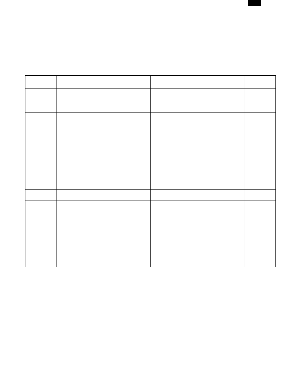
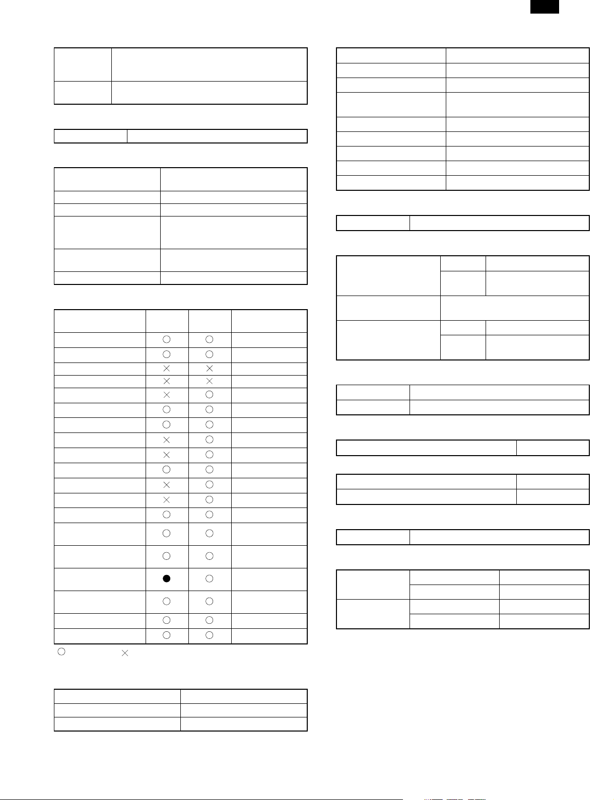
[2] DIFFERENT POINTS FROM THE AL-1600 SERIES
For details of specifications, refer to the basic specifications later.
AL-1600 AL-1610 AL-1620 AL-1621 AL-1640 AL-1650 AL-1670
Copy speed 16sheets/min 16sheets/min 16sheets/min 16sheets/min 16sheets/min 16sheets/min 16sheets/min
Paper feed tray 1step + MB 1step + MB 1step + MB 2step + MB 1step + MB 2step + MB 2step + MB
Duplex print Not available Not available Not available Not available Not available Not available Not available
Shifter (Offset
paper exit)
Page memory None
Scan one
Print multi
Original
detection
(Platen)
Electric Sort No No No No No No
SPF No No
APS No No Available ∗2 Available ∗2 Available ∗ 3 Available ∗2 Available ∗2
AMS No No Available ∗2 Available ∗2 Available ∗3 Available ∗2 Available ∗2
Independent
Zooming
1 set 2 copy No No Available Available Available Available Available
Black-white
reversion
Auto tray
switching
LCD Display No No No No
Printer
Function
(PCL6)
Printer
function (PS2)
∗1 Paper exit style: Group only, sort not available.
∗2 APS/AMS: The document size input is required when reading the OC, only when reading the SPF.
∗3 APS/AMS: The document size input is required.
∗4 AL-1620/1640: APS default OFF
Not available Not available Not available Not available Not available Not available
Standard
provision
(10MB)
No
No No No No No No No
No No Available Available Available Available Available
No No Available Available Available Available Available
No No No Available No Available Available
No No No No
No No No No No No No
Standard
provision ∗1
Standard
provision
(10MB)
Standard
provision ∗1
Standard
provision
Standard
provision
(10MB)
Standard
provision ∗1
Standard
provision
Standard
provision
(10MB)
Standard
provision ∗1
No
Standard
provision
Standard
provision
Standard
provision
(10MB)
Standard
provision ∗1
Standard
provision
Standard
provision
Standard
provision
Standard
provision
Standard
provision (E-
Sort PWB)
Standard
provision
Standard
provision
Standard
provision
Standard
provision
Standard
provision
1 – 1
Page 4
AL-1670
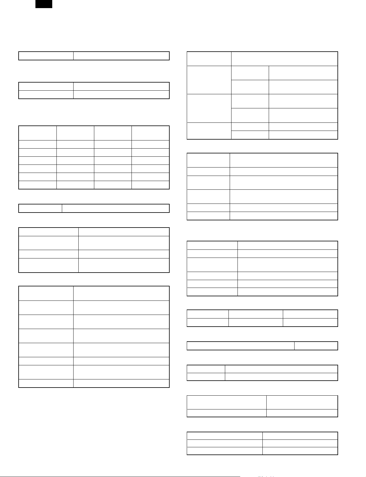
[3] SPECIFICATIONS
1. Copy mode
A. Type
Type Desk-top
B. Copy speed
(1) Basic speed
16 sheets/min
Scan One Print Multi Available
Condition: Copy speed in the normal copy from all the paper feed
ports including the manual paper feed port.
(2) Continuous copy speed (Sheets/min)
Paper size Normal
11" × 17" 9 9 9
8.5" × 14" 10 10 10
8.5" × 13" 10 10 10
8.5" × 11" 16 16 14
8.5" × 11R" 12 12 12
8.5" × 5.5" 16 16 16
Enlargement
(200%)
C. First copy time
First copy time 7.2 sec (11" × 8.5", 1st cassette, with OC)
D. Document
Max. document size 11" × 17"
Document reference
position
Detection (Platen) None
Detection size (SPF)
(1) SPF
Standard/Option
Document load
capacity
Document size
(Max. ∼ Min.)
Document
replacement speed
Document set/Paper
feed direction
Document weight 56 ∼ 90 g/m2, 15 ∼ 23.9 lbs
Document size
detection
Document mixture Not Available
Left side center
11" × 17", 8.5" × 14", 8.5" × 11",
8.5" × 11"R, 8.5" × 5.5"
Standard provision for AL-1650/1670
Not available for AL-1640
30 sheets (56 ∼ 90 g/m2 15 ∼ 23.9 lbs
equivalent)
11" × 17" ∼ 8.5" × 5.5"
16 sheets/min (11" × 8.5" normal copy)
Face up, Center reference, Paper feed
from the top
On the document feed tray
Reduction
(50%)
E. Paper feed
Copy size (Max.
∼ Min.)
Paper feed
system
Paper feed
capacity
(50 ∼ 80 g/m
equivalent)
Remaining
quantity detection
(1) Paper tray section
Paper feed size
Side front Front
Paper feed
capacity
Detection
Weight 56 ∼ 80 g/m2 15 ∼ 21 lbs
Special paper Recycled paper
∗ For 8.5" × 5.5", tray 1 only.
(2) Manual paper feed section
Paper feed size 11" × 17" ∼ 8.5" × 5.5"
Paper feed capacity 100 sheets
Detection
Weight 56 ∼ 128 g/m2 15 ∼ 34 lbs
Special paper Recycled paper, OHP film, labels
Paper feed Single except for recycled paper
(3) Optional paper feed unit
Standard/Option Not available Not available
Cassette: 11" × 17" ∼ 8.5" × 5.5"
AL-1640
AL-1650/1670
AL-1640
2
AL-1650/1670
Cassette Empty detection available
Manual tray Empty detection available
11" × 17", 8.5" × 14", 8.5" × 11", 8.5" ×
11"R, 8.5" × 5.5"
250 sheets (56 ∼ 80 g/m2 15 ∼ 21 lbs
equivalent)
Paper empty detection available, size
detection (by key input)
Size detection not available, paper empty
detection available
1-step paper feed unit 2-step paper feed unit
1 cassette + Multi bypass
tray
2 cassette + Multi bypass
tray
250 × 1 (cassette) + 100
(Multi bypass tray)
250 × 2 (cassette) + 100
(Multi bypass tray)
F. Multi copy
Max. number of multi copy 99 sheets
G. Warmup time
Warmup time Approx. 35 sec (Condition: Standard condition)
Pre-heat Available
H. Copy magnification ratio
Fixed magnification ratio
Zooming 50 ∼ 200%
50, 64, 77, 95, 100, 121,
129, 141, 200%
I. Print density
Density mode Auto/Manual/Photo
No. of manual adjustment 5 steps (Manual/Photo)
Toner save mode Set by the user program
3 – 1
Page 5
AR-1670
J. Void width
Lead edge 1 ∼ 4 mm, rear edge 4 mm or less,
Void area
Image loss
both side 4 mm or less
When using SPF: 6 mm or less
Max. 5/32" (4 mm) (leading and trailing edges)
Max. 5/32" (4 mm) (along other edges in total)
K. Auto duplex
Standard/Option Not installable
L. Paper exit/finishing
Paper exit section
capacity
Job separator Not available
Full detection Not available
Finishing
Offset function
Staple function Not available
Face down 250 sheets
Electronic sort board: Standard
provision for AL-1670
Not available for AL-1640/1650
Available for AL-1670
Not available for AL-1640/1650
M. Additional functions
AL-1640/
1650
APS
AMS
Duplex
Document count
Sorter By E-Sort
Independent zooming
1 set 2 copy
Binding margin
Edge erase
Black-white reversion
2 in 1, 4 in 1
Rotation copy
Memory copy
Pre-heat function
Auto power shut off
Auto tray switching
Message display
User program
Total counter
AL-1670
Condition set by
the user program
Condition set by
the user program
Not available for
AL-1640
Printer condition
only
O. Other specifications
Photoconductor type OPC (Organic Photo Conductor)
Photoconductor drum dia. 30 mm
Copy lamp Xenon lamp
Developing system
Charging system Saw teeth charging
Transfer system (+) DC corotoron
Separation system (–) DC corotoron
Fusing system Heat roller
Cleaning system Contact blade
Dry 2-component magnetic brush
development
P. Package form
Body Body/Accessories
Q. External view
External dimensions
(W × D × H)
Occupying area (W × D)
Weight
AL-1640 590 × 526 × 566 mm
AL-1650/
1670
590 × 526 mm (When the manual
tray is installed.)
AL-1640 Approx. 37 kg
AL-1650/
1670
590 × 526 × 654 mm
Approx. 42 kg
R. Power source
Voltage AC120 V ± 15%
Frequency 60 Hz
S. Power consumption
Max. power consumption About 1.5 KWh
∗ Energy Star standard (The second level conformity)
Pre-heat About 60 Wh
Auto power shut off About 4.8 Wh
T. Noise
Noise BA standard
U. Digital performance
Resolution
Gradation
Reading 400 dpi
Writing 600 dpi
Reading 256 gradations
Writing Binary
: Available : Not available
N. Machine composition
(1) Supply parts
Part name
Toner/developer cartridge AL-160-TD-B
Drum cartridge AL-160-DR
3 – 2
Page 6
AL-1670
2. Printer mode
A. Basic specifications
Item Contents
Print speed 16 PPM
Resolution
Toner save Available
Duplex print
Paper feed tray
Paper size
Paper size
Paper exit
Shifter
Page description
language (standard)
Dot emulation
Page protection
function
Interface
Interface cable
Emulation select Auto
Plug and play Conforming (only with Windows 95/98)
Printer driver
Built-in fonts Outline 45 fonts (PCL6 compatible)
Screen font
Memory
Conforming PC IBM PC-AT compatible
∗: Only AL-1650/1670
∗2: Tray 1 only
600 dpi, 300 dpi (1,200 dpi equivalent by
smoothing)
Available (Only in the model with duplex
function)
Multi bypass tray
Tray 1, Tray 2
A3, B4, A4R, B5R,
A5R, 11" × 17", 8.5"
× 14", 8.5" × 11"R,
Multi bypass tray
Tray 1 ∼ 2∗
Face down system
Available (only AL-1670)
PCL6 emulation
PCL5e emulation
None
Not Available
IEEE1284 port
Use IEEE1284 conforming parallel cable.
(shielded and grounded)
Max. length Within 3.0 m
Microsoft Windows 3.1 Available
Microsoft Windows 95 Available
Microsoft Windows 98 Available
Microsoft Windows
NT4.0
Outline 31 fonts (PCL6 compatible) for
Windows
Standard
8.5" × 5.5"R, 8.5" ×
13", 8.3" × 13", 7.25"
× 10.5"R, DL, C5,
COM10
11" × 17", 8.5" × 14",
8.5" × 11", 8.5" ×
11"R, 8.5" × 5.5" ∗2,
8.5" × 13"
Compatibility mode
Nibble mode
Available
B. Printer driver specifications
(1) System
OS PCL
Microsoft Windows 3.1 Available
IBM PC/AT
(2) Kinds of printer drivers
PCL5e for Windows 3.1/95/98
PCL5e for Windows NT4.0
PCL6 for Windows 95/98
PCL6 (PCL XL) for Windows NT4.0
(3) Set content
Copies 1 to 999
Orientation Portrait, Landscape
Document Style 1-Sided
Paper Source Auto, Tray 1, Tray 2, Bypass Tray
Paper Size
N-Up Printing 1-Up, 2-Up, 4-Up
Border On, Off
Fit to Page On, Off
Toner Save Mode On, Off
Smoothing On, Off
Resolution Settings 600 dpi, 300 dpi
Graphics Mode HP-GL/2 (Vector), Raster
Half Tone
Font Source Resident Fonts, Download Fonts
True Type Mode
Input Tray One Tray, Two Trays
Installed RAM 8MB
Set
content of
custom
paper
Microsoft Windows 95 Available
Microsoft Windows 98 Available
Microsoft Windows NT4.0 Available
Printer driver name Name on PC screen
SHARP AL-1600
Series PCL5e
SHARP AL-1600
Series PCL6
Item PCL6 PCL5e
A3 (297 × 420 mm), B4 (257 × 364
mm), A4 (210 × 297 mm), A5 (148
× 210 mm), B5 (182 × 257 mm),
Ledger (11" × 17"), Letter (8.5" ×
11"), Legal (8.5" × 14"), Executive
(7.25" × 10.5"), Folio (8.3" × 13"),
Invoice (5.5" × 8.5"), Foolscap
(8.5" × 13"), DL, C5, COM10,
Custom Paper
Photo Images, Line Art, Scanned
Images
Download as True Type,
Download as bitmap font, Print as
graphics
Unit 0.01", 0.1 mm
Width
Length
1000 to 2969
(In the case of 0.1 mm)
394 to 1169 (In the case of 0.01")
1480 to 4318
(In the case of 0.1 mm)
583 to 1700 (In the case of 0.01")
3 – 3
Page 7
AL-1670
Item PCL6 PCL5e
Depends on the paper size.
Position
Size 6 ∼ 900
Angle ±90˚
Set
content of
water
mark
(4) Dispaly
a. LCD message
Status LCD display Content
Online Online
Error
User
setting
Text
Edit Fonts Refer to the following Font List.
Edit Density 0 ∼ 255
Transparent Text Yes, No
On First Page Only Yes, No
As Outline Only
AUTO
PCL PCL
HEX HEX
Data Loss
Error
Memory Full Press ENTER
Out of paper
Check Panel
Clear Paper
Path
Main Menu
Press ENTER
Tray 1 <Paper Size>
Tray 2 <Paper Size>
Bypass <Paper Size>
Tray <Paper Size>
Copies
Resolution
Smoothing
Toner Save
Paper Source Tray select
Paper Size Paper size select
Orientation
Emulation Emulation setting
MAX Short –5.84" ∼ 5.84"
Long –8.5" ∼ 8.5"
TOP SECRET
CONFIDENTIAL
DRAFT
ORIGINAL
COPY
Yes, No (Only when Transparent
Text is OFF.)
Auto select to
emulation
When the paper feed
tray is selected to
other than AUTO.
When the paper feed
tray is selected to
AUTO.
Toner empty
Drum replacement
Cover open
Service call error
Paper jam
Paper exit tray full
Printing of the set
quantity is made.
Printing at the set
resolution is made.
Smoothing function
setting.
Toner save mode
setting
Setting of print
direction
Status LCD display Content
If data reception is
Interface
Menu
User
setting
Test Printing
Menu
b. LED display
ON LINE light
DATA light
c. Operation keys
LINE key
MENU key
ITEM key
Left arrow key
Right arrow key
ENTER key Used to enter a new value.
∗ Invalid when the printer is on-line.
(5) PC environment
Computer
Type
Operating
System
CPU
RAM
IBM PC/AT or compatible computer equipped with a
bi-directional parallel interface and CD-ROM drive
Windows 3.1, Windows 95, Windows 98, Windows
NT4.0
Windows 95/3.1 : 486SX or better
Windows 98 : 486DX/66MHz or better (Pentium or
better is recommended.)
Windows NT4.0 : 486/25MHz or better
Windows 95/3.1 : 8MB or more (12MB or more is
recommended.)
Windows 98 : 16MB or more (32MB or more is
recommended.)
Windows NT4.0 : 16MB or more
I/O Time Out
Configuration Page
PCL Font Page
Indicates that the printer is off-line
and data cannot be transferred or
printed. Make settings from the
Extinguished
Lit
Extinguished
Lit
Blinking
Changes between the on-line and off-line modes.
When the printer is on-line, it can receive data
from the computer with which it is connected.
When the printer is off-line, you can use
operation panel keys to make print settings.
Note, however, that you cannot make settings if
the "Data Remaining" message is displayed.
Used to show setting menus on the display in
sequence.∗
Used to show the setting items of the selected
menu in sequence.∗
Used to change the value of any item.∗
operation panel in this mode. Note,
however, that you cannot make
settings if the “Data Remaining”
message is displayed.
Indicates that the printer is on-line
and data can be transferred and
printed.
Indicates that there is no data
being received or processed.
Indicates that the printer is
receiving or processing print data.
Indicates that there is print data
remaining in memory that has not
yet been printed.
not completed within
the set time, it is
judged as a time out
error.
Configuration page is
printed.
PCL6 Font page is
printed.
3 – 4
Page 8
AL-1670
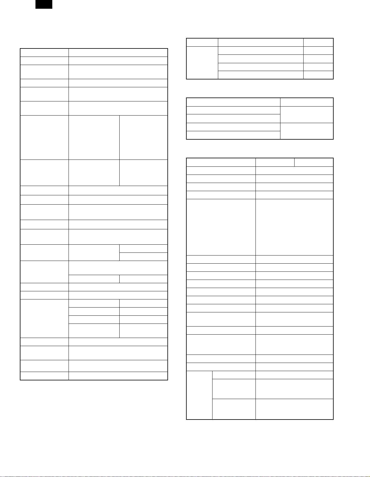
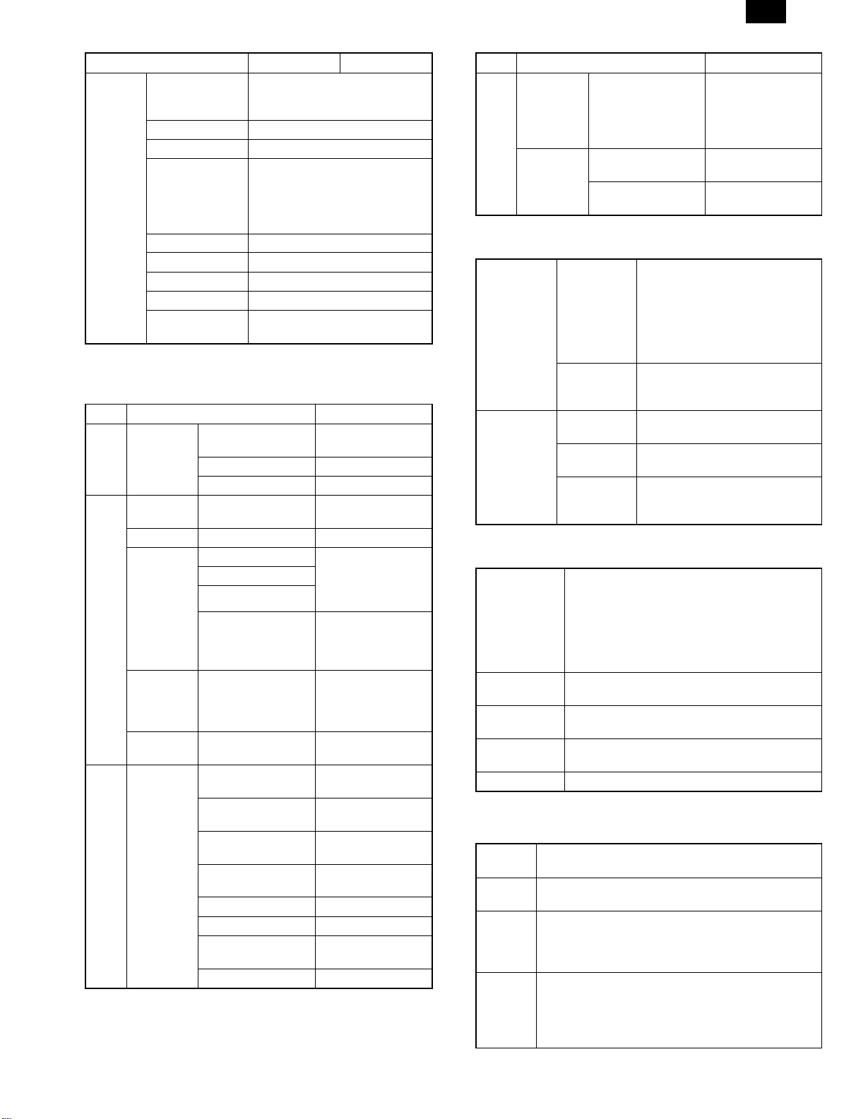
(6) Paper handling specifications
a. Paper feed direction
1) Paper size and image transport direction
Paper Size Side set to the paper feed port
A3 Short side
B4 Short side
A4 Long side
A4R Short side
B5 Long side
B5R Short side
A5 Long side
A5R Short side
Ledger Short side
Legal Short side
Letter Long side
LetterR Short side
Invoice Long side
InvoiceR Short side
Foolscap Short side
Folio Short side
Executive Short side
COM-10 Short side
C5 Short side
DL Short side
Side set to the
paper feed port
= Long side
Transport direction
Side set to the
paper feed port
Transport direction
= Short side
b. Paper feed port
Tray kind Bypass Tray Tray 1 Tray 2
Capacity 100 sheets 250 sheets 250 sheets
A3
B4
A4
A4R
B5
B5R
A5
A5R
Ledger
Legal
Letter
LetterR
Invoice
InvoiceR
Foolscap
Folio
Executive
COM-10
C5
DL
Custom
∗ The number of trays supported depends on each model.
∗ When printing with the multi bypass tray, the printer board cannot
recognize the set paper direction, and therefore it regards that the
short side of paper would be set (vertical transport direction) to
make data.
ABC...
ABC...
For paper feed of the multi bypass tray, the short side must be set
to the paper fed port regardless of paper size for making print
data.
C. Tray selection
Paper handling is controlled on the copier side. The printer board
sends the Video I/F command to the digital copier according to the
computer direction of the tray.
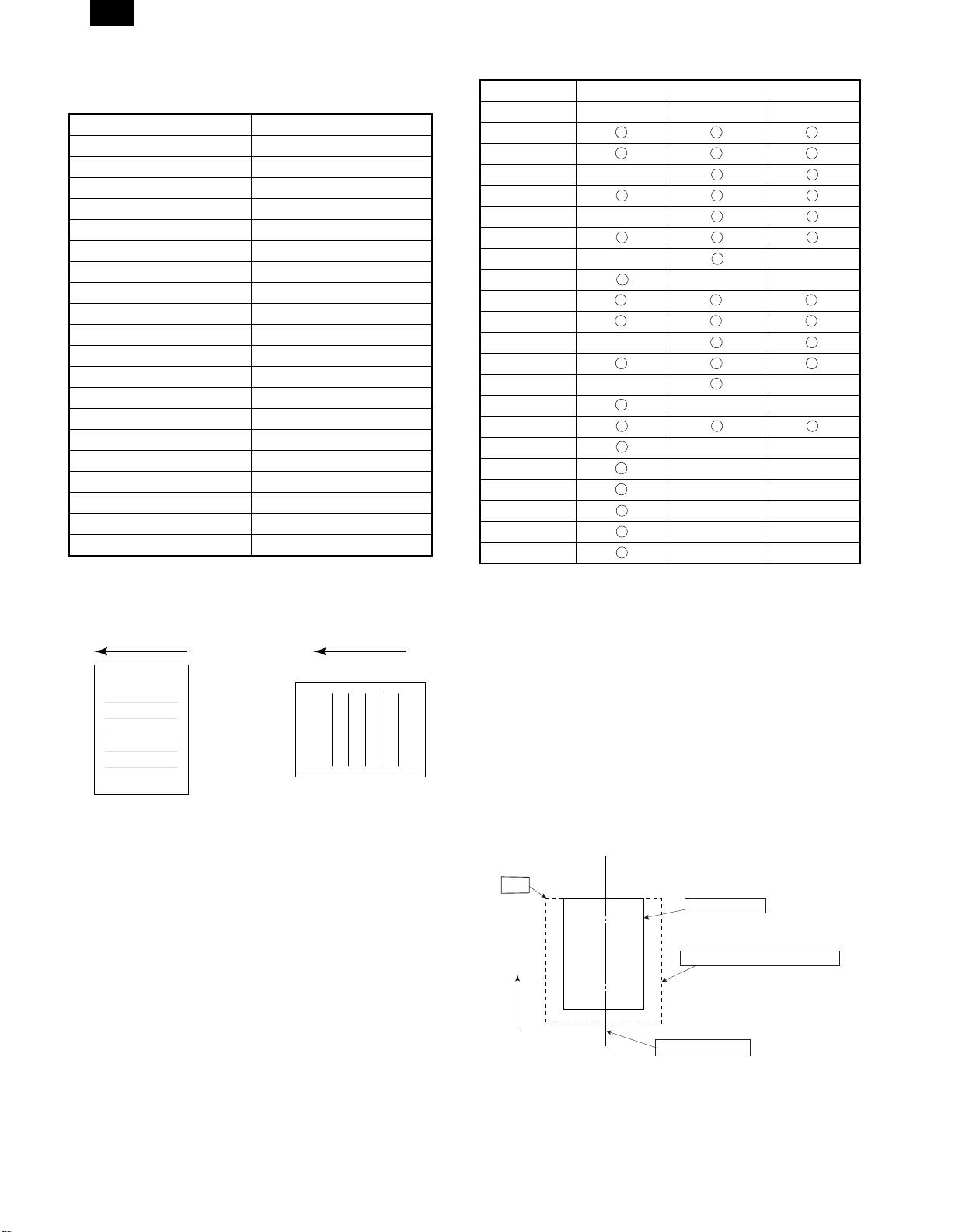
(7) Print reference
This machine employs the center reference system.
Since the digital copier is not equipped with the paper size detection,
format is made not by the actual paper size but by the paper size
specified by the computer, and center distribution is made.
Origin
ABCDEFGHIJKLMN
12345
Paper feed direction
abc
Actual paper size
Size specified by the host computer
Center reference line
3 – 5
Page 9

(8) Print Area
EE
D
AL-1670
H
H
Physical
Page
F
E
D
B
Printable
Area
Logical
Page
HP/GL
Picture
Frame
EE
D
F
F
E
E
D
B
F
E
Paper
size
C
G
A
ABCDEFGH
H
A3 7014 9920 6730 142 100 300 6814 0
B4 6070 8597 5786 142 100 300 5870 0
A4 4960 7014 4676 142 100 300 4760 0
B5 4298 6070 5770 142 100 300 4098 0
A5 3508 4960 3224 142 100 300 3308 0
Ledger 6600 10200 6300 150 100 300 6400 0
Legal 5100 8400 4800 150 100 300 4900 0
Letter 5100 6600 4800 150 100 300 4900 0
Invoice 3300 5100 3000 150 100 300 3100 0
Foolscap 5100 7800 4800 150 100 300 4900 0
Folio 4980 7800 4680 150 100 300 4780 0
Executive 4350 6300 4050 150 100 300 4150 0
COM-10 2474 5700 2174 150 100 300 2274 0
C5 3826 5408 3542 142 100 300 3626 0
DL 2598 5196 2314 142 100 300 2398 0
(Unit: Dots/600DPI)
PAPER
SIZE
C
G
A
Physical
Page
Printable
Area
Logical
Page
HP/GL
Picture
Frame
ABCDEFGH
H
A3 9920 7014 9684 118 100 300 9720 0
B4 8597 6070 8361 118 100 300 8397 0
A4 7014 4960 6778 118 100 300 6814 0
B5 6070 4298 5830 118 100 300 5870 0
A5 4960 3508 4720 118 100 300 4760 0
Ledger 8400 5100 8160 120 100 300 8200 0
Legal 8400 5100 8160 120 100 300 8200 0
Letter 6600 5100 6360 120 100 300 6400 0
Invoice 5100 3300 2860 120 100 300 4900 0
Foolscap 7800 5100 7560 120 100 300 7600 0
Folio 7800 4980 7560 120 100 300 7600 0
Executive 6300 4350 6060 120 100 300 6100 0
COM-10 5700 2474 3460 120 100 300 5500 0
C5 5408 3826 5172 118 100 300 5208 0
DL 5196 2598 4960 118 100 300 4996 0
(Unit: Dots/600DPI)
∗ Top Margin
The set value is received from the digital copier and data are made
according to the set value.
∗ Left margin
Since the paper size sensor is not set, the digital copier does not
know the size and direction of paper inserted. Therefore, the left
margin is set according to the paper size indicated by the print data
sent from the computer, and printing is made. If the computer does
not specify the paper size or in the case of custom size, the left
margin is set according to the default paper size.
3 – 6
Page 10

AL-1670
(9) Font
a. For PCL
TrueDoc Format 45 fonts
1 bitmap font
Font No. Font Name
0 Fixed Pitch 810 Courier Roman SWC
TM
1 Dutch
801 SWC
2 Dutch 801 Bold SWC
3 Dutch 801 Italic SWC
4 Dutch 801 Bold Italic SWC
5 Zapf Humanist 601 SWC
6 Zapf Humanist 601 Bold SWC
7 Zapf Humanist 601 Italic SWC
8 Zapf Humanist 601 Bold Italic SWC
9 Ribbon 131 SWC
10 Clarendon 701 Clarendon Condensed SWC
11 Swiss
TM
742 SWC
12 Swiss 742 Bold SWC
13 Swiss 742 Italic SWC
14 Swiss 742 Bold Italic SWC
15 Swiss 742 Condensed SWC
16 Swiss 742 Condensed Bold SWC
17 Swiss 742 Condensed Italic SWC
18 Swiss 742 Condensed Bold Italic SWC
19 Incised 901 SWC
20 Incised 901 Bold SWC
21 Incised 901 Italic SWC
22 Aldine 430 Original Garamond SWC
23 Aldine 430 Original Garamond Bold SWC
24 Aldine 430 Original Garamond Italic SWC
25 Aldine 430 Original Garamond Bold Italic SWC
26 Audrey Two SWC
27 Flareserif 821 SWC
28 Flareserif 821 Extra Bold SWC
29 Swiss 721 SWM
30 Swiss 721 Bold SWM
31 Swiss 721 Oblique SWM
32 Swiss 721 Bold Oblique SWM
33 Dutch 801 SWM
34 Dutch 801 Bold SWM
35 Dutch 801 Italic SWM
36 Dutch 801 Bold Italic SWM
37 Symbol SWA
38 Wingbats SWM
39 Fixed Pitch 810 Courier Bold SWC
40 Fixed Pitch 810 Courier Italic SWC
41 Fixed Pitch 810 Courier Bold Italic SWC
42 Fixed Pitch 850 Letter Gothic 12 pitch/text SWC
43 Fixed Pitch 850 Letter Gothic Bold 12 pitch/text SWC
44 Fixed Pitch 850 Letter Gothic Italic 12 pitch/text SWC
45 Line Printer
3 – 7
Page 11

[4] LIMITATIONS OF ELECTRICAL SORT <AL-1670 only>
Function Limitations,
When no page memory (SIMM) is additionally installed (16 MB), about 60 sheets
No. of documents
to be read
No. of discharged
paper
2 in 1/4 in 1 copy
Binding margin copy
Edge erase copy Unable to combine with 2 in 1/4 in 1 copy.
of standard documents can be read. (The number of documents to be read
varies depending on image patterns.) When two or more documents are read
and the image memory is full, the image data lamp lights up to stop the
operation.
In sort/group copy, if the number of discharged copy exceeds the following level,
the machine stops copying: 250 sheets (This function default is off)
When the reduction ratio of images exceeds 50%, the reduction ratio of 50% is
active, resulting in broken images. For each reduction ratio, refer to the table
below.
Even though rotation copy is canceled (by the user program), rotation copy may
be made according to necessity.
Unable to combine with the binding margin copy function.
Unable to combine with the edge erase copy function.
Unable to combine with 2 in 1/4 in 1 copy.
Unable to change the binding position and the binding margin.
AL-1670
<When the operation is stopped
with the memory full>
To copy the read data: Start key
To delete the read data: Clear
All key
Remove the discharged paper
and press the START key to
resume copying.
[5] 2 IN 1/4 IN 1 COPY REDUCTION RATIO <AL-1670 only>
When 2 in 1/4 in 1 copy is selected, each image is reduced in the following reduction ratio.
1. 2 in 1 copy
Paper size
11 × 17 8.5 × 14 8.5 × 11 8.5 × 11R 8.5 × 5.5
Document size
2. 4 in 1 copy
Document size
11 × 17
8.5 × 14
8.5 × 11
8.5 × 11R
8.5 × 5.5
11 × 17
8.5 × 14
8.5 × 11
8.5 × 11R
8.5 × 5.5
61% (11 × 17 →
8.5 × 11)
With rotation
74% (8.5 × 14 →
8.5 × 11)
With rotation
97% (8.5 × 11 →
8.5 × 11)
Without rotation
97% (8.5 × 11 →
8.5 × 11)
With rotation
126% (8.5 × 5.5 →
8.5 × 11)
Without rotation
11 × 17 8.5 × 14 8.5 × 11 8.5 × 11R 8.5 × 5.5
50% (11 × 17 →
8.5 × 5.5)
Without rotation
58% (8.5 × 14 →
8.5 × 5.5)
Without rotation
61% (8.5 × 11 →
8.5 × 5.5)
With rotation
61% (8.5 × 11 →
8.5 × 5.5)
Without rotation
97% (8.5 × 5.5 →
8.5 × 5.5)
With rotation
50% (11 × 17 →
8.5 × 5.5)
With rotation
58% (8.5 × 14 →
8.5 × 5.5)
With rotation
61% (8.5 × 11 →
8.5 × 5.5)
Without rotation
61% (8.5 × 11 →
8.5 × 5.5)
With rotation
97% (8.5 × 5.5 →
8.5 × 5.5)
Without rotation
50% Blinking
Without rotation
50% (8.5 × 14 →
7 × 4.25)
Without rotation
50% (8.5 × 11 →
4.25 × 5.5)
With rotation
50% (8.5 × 11 →
4.25 × 5.5)
Without rotation
61% (8.5 × 5.5 →
4.25 × 5.5)
With rotation
50% (11 × 17 →
8.5 × 5.5)
Without rotation
58% (8.5 × 14 →
8.5 × 5.5)
Without rotation
61% (8.5 × 11 →
8.5 × 5.5)
With rotation
61% (8.5 × 11 →
8.5 × 5.5)
Without rotation
97% (8.5 × 5.5 →
8.5 × 5.5)
With rotation
Paper size
50% Blinking
With rotation
50% Blinking
With rotation
50% (8.5 × 11 →
4.25 × 5.5)
Without rotation
50% (8.5 × 11 →
4.25 × 5.5)
With rotation
61% (8.5 × 5.5 →
4.25 × 5.5)
Without rotation
50% (11 × 17 →
8.5 × 5.5)
With rotation
58% (8.5 × 14 →
8.5 × 5.5)
With rotation
61% (8.5 × 11 →
8.5 × 5.5)
Without rotation
61% (8.5 × 11 →
8.5 × 5.5)
With rotation
97% (8.5 × 5.5 →
8.5 × 5.5)
Without rotation
50% Blinking
Without rotation
50% Blinking
Without rotation
50% (8.5 × 11 →
4.25 × 5.5)
With rotation
50% (8.5 × 11 →
4.25 × 5.5)
Without rotation
61% (8.5 × 5.5 →
4.25 × 5.5)
With rotation
50% Blinking
Without rotation
50% Blinking
Without rotation
50% (8.5 × 11 →
4.25 × 5.5)
With rotation
50% (8.5 × 11 →
4.25 × 5.5)
Without rotation
61% (8.5 × 5.5 →
4.25 × 5.5)
With rotation
50% Blinking
With rotation
50% Blinking
With rotation
50% Blinking
Without rotation
50% Blinking
With rotation
50% (8.5 × 5.5 →
4.25 × 2.75)
Without rotation
4 – 1
Page 12

AL-1670
[6] SIMULATION
1. Entering the simulation mode
Perform the following procedure to enter the simulation mode.
Clear key → Exposure mode select key → Clear key → Exposure
mode select key → Main code → Start key → Sub code → Start key
2. Cancelling the simulation mode
When the all clear key is pressed, the simulation mode is cancelled.
When the interruption key is pressed, the process is interrupted and the
screen returns to the sub code entering display.
3. List of simulations
Main
Sub
code
code
1 1 Mirror unit operation check
2 Optical system sensor operation check
2 1 SPF aging B
2 SPF sensor operation check B
3 SPF motor forward rotation operation check B
4 SPF motor reverse rotation operation check B
8 SPF paper feed solenoid operation check B
9 RSPF reverse solenoid operation check A
10 RSPF paper exit gate solenoid operation
check
11 SPF PS release solenoid operation check B
3 2 Shifter job separator sensor operation check D
3 Shifter operation check D
4 Job separator operation check A
11 Shifter home position check D
5 1 Operation panel display check
2 Heater lamp lighting check, cooling fan motor
operation check
3 Copy lamp lighting check
6 1 Paper feed solenoid operation check
10 Main cassette semi-circular roller drive
7 1 Aging with warmup time display
4 Warmup saving
6 Intermittent aging
8 Warmup time display
9 1 Duplex motor forward rotation operation check A
2 Duplex motor reverse rotation operation check A
4 Duplex motor rotation speed adjustment A
5 Duplex motor switchback time adjustment A
10 Toner motor operation check
14 Trouble (except for U2) cancel
16 U2 trouble cancel
20 1 Maintenance counter clear A
21 1 Maintenance cycle setting A
2 Mini maintenance cycle setting (Japan only) A
22 1 Maintenance counter display A
2 Maintenance preset value display A
3 JAM memory display
4 Total JAM counter display
5 Total counter display
6 Developing counter display A
7 Developing preset counter value display
(Japan only)
8 SPF counter display B
9 Paper feed counter display
12 Drum counter display
14 Copier ROM version display
15 Trouble memory display
16 Duplex print counter display A
17 Copy counter display
Contents ∗
A
A
Main
Sub
code
code
22 18 Printer counter display C
19 Electronic sort counter display D
20 FAX print counter display A
21 Scanner counter display
24 1 JAM memory, JAM counter clear
2 Trouble memory clear
4 SPF counter clear B
5 Duplex counter clear A
6 Paper feed counter clear
7 Drum counter clear
8 Copy counter clear
9 Printer counter clear C
10 Electronic sort counter clear D
11 FAX print counter clear A
13 Scanner counter clear
25 1 Main motor operation check
10 Polygon motor operation check
26 1 Option switch display
3 Auditor setting
5 Counter mode setting
6 Destination setting
10 Model name setting
22 Language setting
30 CE mark conformity control setting
32 Fan rotation duty change state setup
38 Cancel of stop at dram life over A
42 Transfer timing adjustment
50 Black-white reversion function setup B
51 Sort/Group copy temporary stop function setup D
30 1 Machine sensor operation check
41 2 OC document sensor adjustment A
3 Document sensor light reception level display A
42 1 Developing counter clear A
43 1 Fusing temperature setting
46 1 Copy density level adjustment
2 FAX density level adjustment A
48 1 Main scanning (front/rear) direction
50 1 Copy image lead edge position adjustment
51 2 Resist amount adjustment
63 1 Shading data check
64 1 Self printing mode
67 14 Printer Flash ROM Data Download C
∗A: Not used in the AL-1600/1610/1620/1621 and
AL-1640/1650/1670.
B: Can be used only in the AL-1620/1621 and AL-1650/1670.
C: Can be used only in the AL-1640/1650/1670.
D: Can be used only in the AL-1670.
magnification ratio adjustment (Copy/FAX/OCSPF common)
2 OC mode sub scanning direction
magnification ratio adjustment in copying
5 SPF mode sub scanning direction
magnification ratio adjustment in copying
6 OC mode sub scanning direction
magnification ratio adjustment in FAX
7 SPF mode sub scanning direction
magnification ratio adjustment in FAX
10 Paper off center adjustment
13 OC mode document off center adjustment
16 SPF mode document off center adjustment B
18 Duplex memory reverse position adjustment A
19 RSPF rear edge void adjustment B
Contents ∗
B
A
A
6 – 1
Page 13

4. Contents of simulations
Main
Sub
code
code
3 11 Shifter Home Position
50 18 Duplex memory reverse
Check
<Used only in the
AL-1670>
position adjustment
<Not used>
19 Duplex rear edge void
adjustment
<Used only in the
AL-1620/1621 and
AL-1650/1670>
Contents Details of operation
Used to drive the shifter motor
Key operation
Feed: Exposure up key
Return: Exposure down key
Moved to Home Position: Magnification ratio display key
After completion of warmup, shading is performed and currently set
value is displayed
Key operation
Memory reverse position adjustment value:
Copy quantity keys
After completion of warmup, shading is performed and currently set
value is displayed.
Key operation Display
Adjustment mode select:
Exposure mode select key
Set value: Copy quantity
keys
Auto: SPF/R-SPF rear edge void
Manual: R-SPF off center <Not used>
Photo: R-SPF lead edge void
<Not used>
AL-1670
Initial
value
Set range
58 1 ∼ 99
50 1 ∼ 99
6 – 2
Page 14

AL-1670
[7] TROUBLE CODE LIST
This chapter is commonly used with the AL-1600 Series.
1. Trouble code list
Trouble
code
E1 00 ERDH board communication trouble D
10 ERDH board trouble D
11 ERDH ASIC error D
12 ERDH CODEC error D
13 ERDH flash ROM error D
14 ERDH RAM error D
15 ERDH page memory error D
16 ERDH SIMM error D
17 Rotation RAM error D
80 ERDH board communication trouble
(Protocol)
81 ERDH board communication trouble
(Parity)
82 ERDH board communication trouble
(Overrun)
84 ERDH board communication trouble
(Framing)
88 ERDH board communication trouble
(Time-out)
E7 03 LSU trouble
04 CCD white level trouble
05 CCD black level trouble
F5 02 Copy lamp error
F6 00 FAX board communication trouble A
10 FAX board trouble A
80 FAX board communication trouble
(Protocol)
81 FAX board communication trouble (Parity) A
82 FAX board communication trouble
(Overrun)
84 FAX board communication trouble
(Framing)
88 FAX board communication trouble
(Time-out)
F9 00 Printer PWB communication trouble C
10 Printer PWB trouble C
80 Printer PWB communication trouble
(Protocol)
81 Printer PWB communication trouble
(Parity)
82 Printer PWB communication trouble
(Overrun)
84 Printer PWB communication trouble
(Framing)
88 Printer PWB communication trouble
(Time-out)
H2 00 Thermistor open detection
H3 00 Heat roller abnormally high temperature
H4 00 Heat roller abnormally low temperature
L1 00 Mirror base feed trouble
L3 00 Mirror base return trouble
Trouble content Remark
Trouble
code
L4 01 Main motor lock
10 Job separator motor abnormality A
L6 10 Polygon motor lock
L8 01 Zero cross pulse (FW) trouble
U2 04 EEPROM serial communication error
11 Counter check sum error
12 Adjustment value check sum error
(EEPROM)
U3 29 Mirror base home position error
D
D
D
D
D
A
A
A
A
C
C
C
C
C
U9 00 Operation control PWB communication
trouble
80 Operation control PWB communication
trouble (Protocol)
81 Operation control PWB communication
trouble (Parity)
82 Operation control PWB communication
trouble (Overrun)
84 Operation control PWB communication
trouble (Framing)
88 Operation control PWB communication
trouble (Time-out)
U95 Operation control PWB connection error
U99 Operation control PWB connection error
Remark:
A: Not used
B: Only AL-1620/1621 and AL1650/1670
C: Only AL-1640/1650/1670
D: Only AL-1670
Trouble content Remark
7 – 1
Page 15

AL-1670
[8] INSTALLING THE PRINTER
DRIVER
To use this printer with your computer, you must install the printer
driver.
Install the printer driver using the supplied SHARP Software CDROM. This kit is supplied with the following printer drivers:
• PCL6 for Windows 95/98
• PCL6 for Windows NT 4.0
• PCL5e for Windows 95/98
• PCL5e for Windows NT 4.0
Note: • It is recommended that you install the PCL6 printer
driver. If you have a problem printing from older
software using the PCL6 driver, remove it and install the
PCL5e driver.
• The printer driver data in the CD-ROM can be copied to
floppy disks.
1. Double-click “My Computer”, “AL-1600” and
“Makedisk”.
2. Double-click “Makedisk.exe”.
3. Follow the on-screen instructions.
Before installation, make sure that:
• You read the README.TXT file which is contained on the
SHARP Software CD-ROM. This file contains the information
and restrictions for using the printer.
• The printer is connected properly with the computer or network.
• The printer is loaded with paper.
• The printer is turned on and on-line (the ON LINE light is lit).
• You quit all application software that is running on your com-
puter.
• Your computer meets the following hardware and software re-
quirements:
Computer Type IBM PC/AT or compatible computer
equipped with a bi-directional parallel
interface and CD-ROM drive
Operating System Windows 95, Windows 98, Windows NT 4.0
CPU Windows 95: 486SX or better
Windows 98: 486DX/66MHz or better
(Pentium or better is
recommended.)
Windows NT 4.0: 486/25MHz or better
RAM Windows 95: 8MB or more (12MB or
more is recommended.)
Windows 98: 16MB or more (32MB or
more is recommended.)
Windows NT 4.0: 16MB or more
This procedure uses the following drive name in examples:
Drive R: CD-ROM drive (holds the CD-ROM containing the
printer drivers)
Change the drive name as required according to your environment.
1. Installing onto Windows 95
This printer is compatible with plug & play. If your computer is incompatible with plug & play, refer to “Installing onto Windows 95/98
without Using the Plug & Play Function”.
1) Turn the computer on and start Windows 95.
Note: Depending on which version of Windows you are using,
the display examples in this step may differ from those on
your system.
• Either the “Update Device Driver Wizard” window or the “New
Hardware Found” window may appear automatically.
Note: If neither the “Update Device Driver Wizard” window nor
the “New Hardware Found” window appear, refer to “Installing Windows 95/98 without Using the Plug & Play
Function”.
• If the “Update Device Driver Wizard” window appears, click the
[Next] button and proceed to step 2).
• If the “New Hardware Found” window appears, perform the
following steps:
<1> Choose “Driver from disk provided by hardware manufac-
turer” and click the [OK] button.
<2> When the “Install From Disk” window appears, insert the
SHARP Software CD-ROM into the CD-ROM drive, type
R:\English\WinXX and click the [OK] button.
Note: In this step the PCL6 printer driver is installed automat-
ically. If you want to install the PCL5e printer driver, refer to
"Installing onto Windows 95/98 without Using the Plug &
Play Function".
<3> Proceed to step 5).
2) Search for the printer driver by clicking [Other Locations...] button.
3) Insert the SHARP Software CD-ROM into the CD-ROM drive, type
R:\WinXX and click the [OK] button.
4) After Windows finds the printer driver, click the [Finish] button to
continue the installation.
Note: In this step the PCL6 printer driver is installed automat-
ically. If you want to install the PCL5e printer driver, refer to
“Installing onto Windows 95/98 without Using the Plug &
Play Function”.
5) Set the printer name.
<1> If you want to change the printer name, enter a new name in
the space provided.
<2> If the program displays, “Do you want your Windows-based
programs to use this printer as the default printer?”, check
“Yes”.
<3> Click the [Next] button.
8 – 1
Page 16

AL-1670
6) Print a test page by clicking the [Finish] button.
Note: If you check “No” and click the [Finish] button, the printer
does not print a test page after the installation.
• The printer driver installation begins.
• If the “Insert Disk” window appears, perform the following
steps:
<1> Click the [OK] button.
<2> When the “Copying Files” window appears, type R:\WinXX
and click the [OK] button.
7) When the test page is printed properly, click the [Yes] button.
• The printer is ready for printing.
2. Installing onto Windows 98
This printer is compatible with plug & play. If your computer is incompatible with plug & play, refer to “Installing onto Windows 95/98
without Using the Plug & Play Function”.
1) Turn the computer on and start Windows 98.
• The “Add New Hardware Wizard” window appears automat-
ically, click the [Next] button.
Note: If the “Add New Hardware Wizard” window does not ap-
pear in this step, refer to “Installing onto Windows 95/98
without Using the Plug& Play Function”.
3) Click the [Have Disk...] button.
4) Insert the SHARP Software CD-ROM into the CD-ROM drive, type
R:\WinXX, and click the [OK] button.
5) Choose the appropriate printer driver from those listed below and
click the [Next] button.
• PCL6 Printer Driver: SHARP AL-1600 Series PCL6
• PCL5e Printer Driver: SHARP AL-1600 Series PCL5e
Note: It is recommended that you install the PCL6 printer driver.
If you have a problem printing from older software using
the PCL6 driver,remove it and install the PCL5e driver.
2) Display a list of all the printer drivers by checking “Display a list of
all the drivers in a specific location, ...” and clicking the [Next]
button.
6) After Windows finds the printer driver, click the [Next] button to
continue the installation.
7) Set the printer name.
<1> If you want to change the printer name, enter a new name in
the space provided.
<2> If the program displays, "Do you want your Windows-based
programs to use this printer as the default printer?", check
"Yes".
<3> Click the [Next] button.
8) Print a test page by clicking the [Finish] button.
Note: If you check “No” and click the [Finish] button, the printer
does not print a test page after the installation.
• The printer driver installation begins.
8 – 2
Page 17

9) When the test page is printed properly, click the [Yes] button.
• The printer is ready for printing.
3. Installing onto Windows 95/98 without Using the
Plug & Play Function
Computers using Windows 95 or Windows 98 that are compatible
with plug & play can install the printer driver automatically. However,
if your computer is incompatible with plug & play, follow the procedure in this section.
The following steps use Windows 98 in display examples.
1) Turn the computer on and start Windows 95/98.
2) Click the Start menu, point to “Settings”, and choose “Printers”.
3) When the “Printers” window appears, double-click the “Add
Printer” icon.
4) Click the [Next] button.
5) If the screen for choosing the connection method appears, choose
"Local printer" or "Network printer" and click the [Next] button.
Note: This screen appears only when the computer is connected
to a network.
• If you choose “Network printer” you must specify a network
path or queue name.
Contact your network administrator for details.
The following steps use the example of a local printer.
AL-1670
9) Choose the port and click the [Next] button.
10) Set the printer name.
<1> If you want to change the printer name, enter a new name in
the space provided.
<2> If the program displays, “Do you want your Windows-based
programs to use this printer as the default printer?”, check
“Yes”.
<3> Click the [Next] button.
6) Click the [Have Disk...] button.
7) Insert the SHARP Software CD-ROM into the CD-ROM drive, type
R:\WinXX, and click the [OK] button.
8) Choose the appropriate printer driver from those listed below and
click the [Next] button.
• PCL6 Printer Driver: SHARP AL-1600 Series PCL6
• PCL5e Printer Driver: SHARP AL-1600 Series PCL5e
Note: It is recommended that you install the PCL6 printer driver.
If you have a problem printing from older software using
the PCL6 driver,remove it and install the PCL5e driver.
11) Print a test page by clicking the [Finish] button.
Note: If you check “No” and click the [Finish] button, the printer
does not print a test page after the installation.
• The printer driver installation begins.
12) When the test page is printed properly, click the [Yes] button.
• The printer is ready for printing.
8 – 3
Page 18

AL-1670
4. Installing onto Windows NT 4.0
1) Turn the computer on and start Windows NT.
2) Click the Start menu, point to “Settings”, and choose “Printers”.
3) When the “Printers” window appears, double-click the “Add
Printer” icon.
4) Choose “My Computer” or “Network printer server” and click the
[Next] button.
• The following steps use “My Computer” as an example.
For more information about using this printer as a network
printer, refer to the Windows NT 4.0 networking documentation.
5) Check the checkbox for the port you are using and click the [Next]
button.
9) Set the printer name.
<1> If you want to change the printer name, enter a new name in
the space provided.
<2> If the program displays, “Do you want your Windows-based
programs to use this printer as the default printer?”, check
“Yes”.
<3> Click the [Next] button.
6) Click the [Have Disk...] button.
7) Insert the SHARP Software CD-ROM into the CD-ROM drive, type
R:\WinNT and click the [OK] button.
10) Make the appropriate settings for your environment.
• When using print sharing, choose “Shared” and enter a share
name. If necessary for your environment, select Windows 95
from the list of operating systems.
• If you are not using shared printing, choose “Not shared”.
After making the settings on this screen, click the [Next] button.
11) Print a test page by clicking the [Finish] button.
Note: If you check “No” and click the [Finish] button, the printer
does not print a test page after the installation.
• The printer driver installation begins.
8) Choose the appropriate printer driver from those listed below and
click the [Next] button.
• PCL6 Printer Driver:SHARP AL-1600 Series PCL6
• PCL5e Printer Driver:SHARP AL-1600 Series PCL5e
Note: It is recommended that you install the PCL6 printer driver.
If you have a problem printing from older software using
the PCL6 driver,remove it and install the PCL5e driver.
12) When the test page is printed properly, click the [Yes] button.
• The printer is ready for printing.
5. Changing Printer Configuration Settings
After installing the printer driver use the procedure in this section to
change the printer configuration settings. Also refer to the print driver
help for more information.
1. Click the Start menu, point to “Settings”, and choose “Printers”.
2. Right-click the appropriate printer and choose “Properties”
fromthe menu.
3. Click the Configuration tab and change the printer settings.
8 – 4
Page 19

DATA
ON LINE MENU ITEM
ENTER
DATA
ON LINE MENU ITEM
ENT
DATA
ON LINE MENU ITEM
ENT
DATA
ENTER
DATA
NE MENU ITEM
ENTER
AL-1670
[9] SETTING AND ADJUSTMENTS
1. Configuration setting
MENU
ITEM
Main Menu
Copies
1*
Resolution
600 *
Smoothing
On *
Toner Save
Off *
Paper Source
Auto *
Paper Size
A4
*
Orientation
Portrait *
Emulation
PCL *
ONLINE
MENU
Test Printing Menu
Configuration Page
PCL Font List
MENU
2) Press the MENU key repeatedly until the required menu appears.
3) Press the ITEM key repeatedly until the required item appears.
4) Press the Left or Right arrow key to change the setting.
• The current value is marked with an asterisk (∗).
Interface Menu
I/O Time Out
60 second *
(Basic Menu Setting Procedure)
Note: The menus and items displayed may be different depending
on the optional functions installed.
1) When the printer is not in use, press the ON LINE key to put the
printer off-line.
5) After choosing the required value, press the ENTER key.
• The new value is registered.
9 – 1
Page 20

DATA
ON LINE MENU ITEM
ENTER
DATA
ON LINE MENU ITEM
ENT
DATA
ON LINE MENU ITEM
ENT
DATA
NE MENU ITEM
ENTER
AL-1670
A. Main Menu
Item
Copies 1 ∼ 999 Sets how many copies to print.
Resolution
Smoothing
Toner Save
Paper
Source
Paper Size
Orientation
Emulation
Possible
Settings
600dpi ∗
300dpi
On ∗
Off
On
Off ∗
Auto ∗
Tray 1
Tray 2∗
Bypass Tray
A3
B4
A4∗
B5
A5
Ledger
Legal
Letter∗
Executive
Folio
Invoice
Foolscap
COM-10
DL
C5
Portrait ∗
Landscape
PCL ∗
HEX
Description
Sets the printing resolution.
Sets whether smoothing is done or not.
This function improves the appearance
of printed documents by smoothing the
angles and curves of images. This
allows printing at a higher apparent
resolution. For example, if the printer is
set to 600dpi, resolution equivalent to
1200dpi can be achieved.
When printing image data, you may
need to select "Off" to achieve best
results.
Sets whether toner save mode is in
effect or not. This function prints slightly
fainter to save toner. This item is
different from the copier “toner save
mode”.
Sets the tray used for paper feeding.
Setting to “Auto” automatically selects
the paper tray loaded with the paper of
the size specified in the “Paper Size”
item.
∗ The available settings reflect the
installed trays.
Sets the size of the paper where data
will be printed. If this size is different
from the paper size present in the tray,
the size set on the operation panel takes
precedence.
∗ Depending on where the printer was
purchased, the default value is either A4
or Letter.
Sets the page orientation for printing.
Specify “Portrait” to print the paper with
its long side (longer edge) vertical.
Specify “Landscape” to print the paper
with its long side (longer edge) horizontal.
Specifies the printer language used.
[10] CONFIGURATION REPORT
AND TEST PAGE
To test print the configuration page and font list, use the following
procedure:
1) Press the ON LINE key to switch the printer to the offline mode.
2) Press the MENU key to display the Test Menu.
3) Press the ITEM key to display the required item.
4) Press the ENTER key.
The test page prints.
C. Interface Menu
I/O Time Out
D. Test Menu
Configuration Page Prints the configuration page.
PCL Font List Prints the PCL6 font list.
Item Setting Choice Description
1 second
:
60 second ∗
:
999 second
Sets I/O time-out. If
no data is received
within the preset
time, print
processing is ended.
Item Description
9 – 2
Page 21

AL-1670
1. Samples
Printer Configuration Page
HARDWARE STATUS
Machine Information
Language:
Hardware Specs
Base Memory:
Total Memory:
Network Board:
Version Information
PCL:
Input Paper Trays
Bypass Tray:
Tray 1:
Tray 2:
KEY MENU STATUS
Main Menu
Copies:
Resolution:
Smoothing:
Toner Save:
Paper Source:
Paper Size:
Orientation:
Emulation:
PCL is a registered trademark of Hewlett-Packard Cmpany. All other trademarks and copyrights are the property of their respective owners.
1
600dpi
On
Off
Auto
Letter (8.5x11)
Portrait
PCL
English
8MB
8MB
Not Installed
1.xx
-Size-
Paper Inserted
Letter (8.5x11)
Letter (8.5x11R)
Interface Menu
I/O Time Out 60 sec.
2. Items and contents
A. Hardware status
(Machine information)
a. Language
Value: (English/French/German/Italian/Dutch/Spanish/Swedish)
Example: English
Default: Depends on the Destination setting
Description: Depends on the LCD display, the configuration page,
and the font list language.
(Hardware specifications)
a. Base memory
Value: 8MB
Example: 8MB
Default: 8MB
Description: Indicates the printer PWB base memory capacity.
b. Total memory
Value: 8MB
Example: 8MB
Default: 8MB
Description: Indicates the printer PWB total memory capacity, which
is the total of the base memory and the option memory.
c. Network board
Value:
Example: Not Installed.
Default: Not Installed.
Description: Ubducates the network board installation status.
(Firmware version)
a. PCL6
Value: #.##
Example: 1.00
Default: Depends on the printer firmware version.
Available Paper Size
Appearance on Configuration Page Description
Letter (8 1/2 × 11) Letter/Long Edge Feed
Letter (8 1/2 × 11R) Letter/Short Edge Feed
Legal (8 1/2 × 14) Legal/Short Edge Feed
Ledger (11 × 17) Ledger/Short Edge Feed
Executive (7 1/4 × 10 1/2) Executive/Short Edge Feed
Invoice (5 1/2 × 8 1/2) Invoice/Long Edge Feed
Foolscap (8 1/2 × 13) Foolscap/Short Edge Feed
A4 A4/Long Edge Feed
A4R A4/Short Edge Feed
B5 B5/Long Edge Feed
B5R B5/Short Edge Feed
B4 B4/Short Edge Feed
A3 A3/Short Edge Feed
A5 A5/Long Edge Feed
A6 A6/Short Edge Feed
(Unknown) Other size (EXTRA)
(No Paper) No paper available on this tray.
(No Tray)
There is a problem with this
tray.
This tray is opened (except
(Tray Open)
Bypass-Tray) or Tray is lifting
up.
a. Manual paper feed tray
Value: (Suitable paper size)
Example: Letter (8 1/2 × 11")
Default: Depends on the size of paper set on the manual paper
feed tray.
Description: Indicates the size of paper set on the manual paper feed
tray. Depends on the paper size detected on the manual
paper feed tray. “Unclear” means that the paper size is
not detected. If there is no paper, no print is made here.
b. Tray 1, tray 2
Value: (Suitable paper size)
Example: Letter (8 1/2 × 11")
Default: Depends on the paper tray configuration.
Description: Indicates the paper size configuration of tray 1, tray 2
9 – 3
Page 22

AL-1670
[11] Disassembly and assembly
A Printer Board
B E-sort PWB (only AL-1670)
A. Printer board
B. E-sort PWB <Only AL-1670>
M3x6
M3x6
M3x6
M3x6
M3x6
M3x6
11 – 1
M3x6
M3x6
M3x6
M3x6
M3x6
Page 23

[12] FLASH ROM VERSION UP
PROCEDURE
1. MCU/E-SORT
A. Tool
● Machine
● PC
Operates on Windows 95/98.
● Level converter (UKOG-0002QSZZ) (with serial cable)
● Level converter (UKOG-0003QSZZ) (without serial cable)
● (Serial cable)
B. Procedures
1) Connect the PC and the level converter, and start Windows.
2) Turn off the power of the machine.
3) Remove the cap at the rear of the machine.
AL-1670
7) Communication port/communication speed setting
● Select “Comport” in the option menu, and select the most
suitable item with consideration of PC environment, work time,
etc.
4) Connect the serial connector.
5) Turn on the power of the machine.
● The machine enters the download mode. (All LED lamps are
turned off. The machine accepts no key operations.)
6) Execute “mainte-Vxxx.exe” on the PC.
8) Select “Download the Program Data” in the SPECIAL folder, and
transfer data.
∗ Use “mainte_vxxx.exe” ver.1.04 or later.
12 – 1
Page 24

AL-1670
9) Select the data for MCU to be transferred.
10) Select the data for the electronic sort board to be transferred.
∗ For the models other than the AL-1670, go to procedure 11).
2. Printer Board
A. Cases where flash memory rewriting is required
In the following cases, the program in the printer control PWB flash
memory must be rewritten.
1) When a bug or other error is found
2) Data stored in the flash memory is destroyed or deleted.
3) When the flash memory is replaced.
B. Necessary tools
1) Computer (PC) <Operates on MS-DOS.>
2) Parallel cable
3) Program data file (xxx.BIN)
C. Procedure
1) Print the configuration list to check the firmware version.
Use the operation panel of the copier to perform the following procedure.
ONLINE <off line> → MENU <Test Printing Menu> → ITEM <Configuration Page> → ENTER <The test page prints>
2) Connect the PC and the copier with the parallel cable.
3) Turn on the power
4) Execute SIM 67-14.
“Erase Flash Data?” is displayed on the LCD.
5) Press the ENTER key on the copier’s operation panel.
“Now Erasing” is displayed on the LCD.
6) After deletion of data, “Please Send Data” is displayed on the LCD
and the machine enters the ready state for data input.
7) Download the program file.
(Note) Never turn off the power during download.
Set the PC to DOS mode → Check that the display shows
READY. → Then type COPY /B xxx.BIN LPT1:
and press the enter key.
( : space)
11) After transfer of data, turn off the machine and disconnect the connector.
Reference: If the power is turned off during the procedure or in case
of a communication error, resume the procedure from 2).
8) The machine enters the data reception mode.
While “Writing” is displayed on the LCD, data are written into the
flash ROM.
9) When data reception and data writing into the flash ROM are completed, the SUM check is automatically performed.
(Note) In case of an error, “Sum check Error” is displayed.
Turn off the power once, and repeat the procedures from 3).
10) If there is no problem on the result of the SUM check, “Complete”
is displayed on the LCD.
11) Turn off/on the power to print the configuration page with the
above procedures, and check the firmware version.
12) Perform printing on the PC side and check that printing is per-
formed normally.
12 – 2
Page 25

AL-1670
COPYRIGHT © 1999 BY SHARP CORPORATION
All rights reserved.
Printed in Japan.
No part of this publication may be reproduced,
stored in a retrieval system, or transmitted,
in any form or by any means,
electronic, mechanical, photocopying, recording, or otherwise,
without prior written permission of the publisher.
Trademark acknowledgments
Windows and Windows NT are trademarks of Microsoft Corporation in the U.S.A. and other countries.
IBM and PC/AT are trademarks of International Business Machines Corporation.
PCL is a trademark of Hewlett-Packard Company.
Pentium is a registered trademark of Intel Corporation.
All other trademarks and copyrights are the property of their respective owners.
SHARP CORPORATION
Digital Document Systems Group
Quality & Reliability Control Center
Yamatokoriyama, Nara 639-1186, Japan
1999 June Printed in Japan N
 Loading...